WO2023176864A1 - 体内に挿入される医療用装置の遠位端部に用いられるチップ、及び医療用装置 - Google Patents
体内に挿入される医療用装置の遠位端部に用いられるチップ、及び医療用装置 Download PDFInfo
- Publication number
- WO2023176864A1 WO2023176864A1 PCT/JP2023/009980 JP2023009980W WO2023176864A1 WO 2023176864 A1 WO2023176864 A1 WO 2023176864A1 JP 2023009980 W JP2023009980 W JP 2023009980W WO 2023176864 A1 WO2023176864 A1 WO 2023176864A1
- Authority
- WO
- WIPO (PCT)
- Prior art keywords
- fixed
- medical device
- distal end
- chip
- opposing surface
- Prior art date
- Legal status (The legal status is an assumption and is not a legal conclusion. Google has not performed a legal analysis and makes no representation as to the accuracy of the status listed.)
- Ceased
Links
Images





Classifications
-
- A—HUMAN NECESSITIES
- A61—MEDICAL OR VETERINARY SCIENCE; HYGIENE
- A61F—FILTERS IMPLANTABLE INTO BLOOD VESSELS; PROSTHESES; DEVICES PROVIDING PATENCY TO, OR PREVENTING COLLAPSING OF, TUBULAR STRUCTURES OF THE BODY, e.g. STENTS; ORTHOPAEDIC, NURSING OR CONTRACEPTIVE DEVICES; FOMENTATION; TREATMENT OR PROTECTION OF EYES OR EARS; BANDAGES, DRESSINGS OR ABSORBENT PADS; FIRST-AID KITS
- A61F2/00—Filters implantable into blood vessels; Prostheses, i.e. artificial substitutes or replacements for parts of the body; Appliances for connecting them with the body; Devices providing patency to, or preventing collapsing of, tubular structures of the body, e.g. stents
- A61F2/95—Instruments specially adapted for placement or removal of stents or stent-grafts
-
- A—HUMAN NECESSITIES
- A61—MEDICAL OR VETERINARY SCIENCE; HYGIENE
- A61M—DEVICES FOR INTRODUCING MEDIA INTO, OR ONTO, THE BODY; DEVICES FOR TRANSDUCING BODY MEDIA OR FOR TAKING MEDIA FROM THE BODY; DEVICES FOR PRODUCING OR ENDING SLEEP OR STUPOR
- A61M25/00—Catheters; Hollow probes
Definitions
- the present invention relates to a chip used at the distal end of a medical device inserted into the body, and a medical device.
- Patent Document 1 discloses a tube body having an inner layer, a reinforcing body covering the inner layer, and an outer layer covering the reinforcing body, and a tubular tip made of metal provided at the distal end of the tube body.
- a catheter is disclosed which includes a tip, a slit is formed in the distal tip, an outer coating is provided on the outer peripheral surface of the distal tip, and the outer coating is inserted into the inside of the slit.
- the distal tip of Patent Document 1 is provided with a spiral slit extending in the axial direction in order to make the tip easier to bend as a whole, but since the outer covering is inside the slit, the material of the outer covering is Depending on the situation, there was a possibility that the tip would hardly bend.
- a stent delivery catheter is often used to place a stent in a stenotic area. There was a need to improve the ease of insertion.
- the present invention has been made in view of the above-mentioned problems, and its purpose is to provide a tip that is less likely to damage contact tissue and that is easier to insert into a stenotic site. Another object is to provide a medical device that is less likely to damage contact tissues and that is easier to insert into a stenotic site.
- a chip used in the distal end of the medical device according to the embodiment of the present invention which can solve the above problems, is as follows. [1] A chip used at the distal end of a medical device inserted into the body, a first member including a proximal end of the tip; a second member located on the distal side of the distal end of the first member; The first member has a first opposing surface facing the second member, and the first opposing surface includes a first fixing part fixed to the second member and a first fixing part fixed to the second member. A chip that does not have a non-fixed part.
- the first opposing surface has the non-fixed part, a gap is formed between the first member and the second member that functions as a buffer part, and the chip becomes partially flexible. , the tip becomes less likely to damage the tissues it comes in contact with in the body. Furthermore, since the first opposing surface has the fixing portion, the first member and the second member are fixed in the distance direction, making it easier to push the tip into the stenosis from the proximal side to the distal side. .
- the chip according to the embodiment of the present invention is preferably one of the following [2] to [12].
- the first member has a lumen extending from the proximal end to the distal end,
- the chip according to [1], wherein the second member has a lumen extending from the proximal end to the distal end and communicating with the lumen.
- the chip according to [2], wherein the non-fixed portion is located closer to the lumen than the first fixed portion.
- the first opposing surface has a second fixing part fixed to the second member, The chip according to [2] or [3], wherein the second fixed part is located closer to the lumen than the non-fixed part.
- the first member includes a first resin
- the chip according to any one of [1] to [10], wherein the first opposing surface is fixed to the second member by welding at the first fixing portion.
- the medical device is a medical tubular body transport device that transports a medical tubular body into the body.
- a medical device that can solve the above problem is as shown in [13] below, and preferably any one of [14] to [16].
- a medical device inserted into the body, an inner tube; an outer tube having at least a portion of the inner tube disposed in a lumen; The chip according to any one of [1] to [12], which is fixed to at least a portion of the distal end of the inner tube; A medical device having a medical device disposed between an outer surface of the distal end of the inner tube and an inner surface of the outer tube.
- the medical device according to [13], wherein the distal end of the medical device is located closer to the non-fixed portion of the first opposing surface.
- the present invention with the above configuration, it is possible to provide a tip that is difficult to damage contact tissue and that is easy to insert into a stenosis site. Further, according to the present invention, it is possible to provide a medical device that does not easily damage contact tissues and is easy to insert into a stenotic site.
- FIG. 1 is a side view of a chip according to an embodiment.
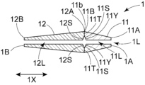
- FIG. 2 is an axial cross-sectional view of FIG. 1.
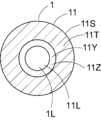
- FIG. 3 is a cross-sectional view taken along the line AA in FIG.
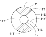
- FIG. 4 is a sectional view showing a modification of the cross section of FIG.
- FIG. 5 is a sectional view showing a modification of the cross section of FIG.
- FIG. 6 is an axial cross-sectional view of a chip according to another embodiment.
- FIG. 7 is a sectional view showing a modification of the cross section of FIG.
- FIG. 8 is a sectional view showing a modification of the cross section of FIG.
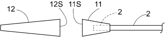
- FIG. 9 is a side view showing the first member fixed to the inner tube and the second member before being fixed to the first member.
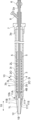
- FIG. 10 is a side view of the medical device according to the embodiment.
- FIG. 11 is an axial cross-sectional view of FIG. 10.
- FIG. 12 is an axial cross-sectional view of a medical
- a chip according to an embodiment of the present invention is a chip used at a distal end of a medical device inserted into a body, and includes a first member including a proximal end of the chip, and a distal end of the first member. and a second member located distally from the end, the first member having a first opposing surface facing the second member, and the first opposing surface being fixed to the second member.
- the first fixed part is fixed to the second member, and the non-fixed part is not fixed to the second member.
- the first opposing surface has the non-fixed part, a gap is formed between the first member and the second member that functions as a buffer part, and the chip becomes partially flexible. , the tip becomes less likely to damage the tissues it comes in contact with in the body. Furthermore, since the first opposing surface has the fixing portion, the first member and the second member are fixed in the distance direction, making it easier to push the tip into the stenosis from the proximal side to the distal side. .
- FIG. 1 is a side view of a chip according to an embodiment.
- FIG. 2 is an axial cross-sectional view of FIG. 1.
- FIG. 3 is a cross-sectional view taken along the line AA in FIG. 4, 5, 7, and 8 are cross-sectional views showing modifications of the cross-section of FIG. 3.
- FIG. 6 is an axial cross-sectional view of a chip according to another embodiment.
- FIG. 9 is a side view showing the first member fixed to the inner tube and the second member before being fixed to the first member.
- FIG. 10 is a side view of the medical device according to the embodiment
- FIG. 11 is a cross-sectional view in the axial direction of FIG. 10.
- FIG. 12 is an axial cross-sectional view of a medical device according to another embodiment.
- a chip 1 shown in FIG. 1 is a chip used at the distal end of a medical device inserted into the body.
- the tip 1 is preferably a tip used at the distal end portion 10b of the medical device 10 for transporting the medical device 4 into the body.
- the tip 1 includes a first member 11 including a proximal end 1A of the tip 1, and a second member 12 located distal to the distal end 11b of the first member 11. It has The first member 11 has a first opposing surface 11S that faces the second member 12, and the first opposing surface 11S has a first fixing portion 11T fixed to the second member 12 and a first opposing surface 11S that faces the second member 12. It has a non-fixed portion 11Y that is not fixed.
- the first opposing surface 11S has the non-fixed portion 11Y, a gap is formed between the first member 11 and the second member 12, which functions as a buffer portion. As a result, the tip 1 becomes partially flexible, making it difficult for the tip 1 to damage the tissue it contacts within the body. Furthermore, since the first opposing surface 11S has the first fixing portion 11T, the second member 12 can be easily pushed into the distal side by the first member 11.
- the first member 11 and the second member 12 each extend in the axial direction 1X of the chip 1. This makes it easier to push the chip 1 in the axial direction 1X. Further, it is preferable that the axial direction of the first member 11 and the axial direction of the second member 12 are the same direction.
- the first fixing portion 11T of the first opposing surface 11S only needs to be fixed to the second member 12.
- a method of fixing the first fixing part 11T to the second member 12 for example, a part of the first opposing surface 11S of the first member 11 is brought into contact with the second opposing surface 12S of the second member 12 and fixed by welding.
- a method of fixing a part of the first opposing surface 11S of the first member 11 to the second opposing surface 12S of the second member 12 with an adhesive can be cited.
- the second opposing surface 12S is a surface of the second member 12 that faces the first member 11.
- the first opposing surface 11S is preferably fixed to the second member 12 by welding at the first fixing portion 11T. Since welding improves the fixing strength between the first member 11 and the second member 12, it is possible to make it easier to push the second member 12 distally by the first member 11.
- the longest straight line distance in the axial direction 1X from the first opposing surface 11S to the second opposing surface 12S is preferably 0.1 times or more, and 0.2 times or more the maximum outer diameter of the first member 11. It is more preferable that there be. This makes it easier for the gap between the first member 11 and the second member 12 to function as a buffer.
- the longest linear distance is preferably 0.5 times or less, more preferably 0.4 times or less, and even more preferably 0.3 times or less than the maximum outer diameter of the first member 11. preferable. This makes it easier to push the chip 1 in the axial direction 1X.
- the angle between the outer edge of the first fixing portion 11T and the axial direction 1X is preferably 80 degrees or more and 100 degrees or less, and 85 degrees or more, It is more preferably 95 degrees or less, and even more preferably 88 degrees or more and 92 degrees or less.
- the angle between the outer edge of the first fixing portion 11T and the axial direction 1X is closer to 90 degrees, it is easier to push the second member 12 distally by the first member 11.
- the first member 11 has a lumen 11L extending from a proximal end 11A to a distal end 11B
- the second member 12 has a lumen 11L extending from a proximal end 12A to a distal end 12B. It is preferable to have a lumen 12L communicating with the lumen 11L. This allows the flexibility of the chip 1 to be improved. Furthermore, a long body such as a guide wire can also be inserted into the inner cavities 11L and 12L.
- the non-fixed part 11Y is preferably located closer to the inner cavity 11L than the first fixed part 11T.
- the gap formed by the non-fixed portion 11Y arranged in this way buffers the force applied from the distal end 1B to the proximal end 1A of the tip 1, making it easier to avoid the tip 1 from penetrating the contact tissue. I can do it.
- the first opposing surface 11S does not have a fixed part fixed to the second member 12 on the side closer to the inner cavity 11L than the non-fixed part 11Y. This forms a gap that communicates with the inner cavity 1L, making it easier to buffer the force applied from the distal end 1B to the proximal end 1A of the tip 1.
- the non-fixed portion 11Y is preferably a groove 11Z extending in the circumferential direction of the inner cavity 11L.
- the groove 11Z extending in the circumferential direction makes it easier to buffer the force applied from the distal end 1B to the proximal end 1A of the tip 1.
- the groove 11Z is preferably V-shaped or U-shaped, more preferably U-shaped. It is preferable that the groove 11Z does not extend in the axial direction 1X. Thereby, the ability of the chip 1 to break through the stenosis can be improved.
- the maximum depth of the groove 11Z is preferably 0.1 times or more, more preferably 0.2 times or more the maximum outer diameter of the first member 11. This makes it easier for the groove 11Z to function as a buffer. On the other hand, the maximum depth of the groove 11Z is preferably 0.4 times or less, more preferably 0.3 times or less, the maximum outer diameter of the first member 11. This makes it easier to push the chip 1 in the axial direction 1X.
- the groove 11Z extends in a part of the circumferential direction and does not extend all the way around the circumferential direction. This makes it easier for the second member 12 to bend slightly toward the groove 11Z when a force is applied in the axial direction 1X, making it easier to avoid the tip 1 sticking into the contact tissue.
- the non-fixed part 11Y has a part located closer to the inner cavity 11L than the first fixed part 11T, and a part not located closer to the inner cavity 11L than the first fixed part 11T. You can leave it there. This makes it easier for the tip 1 to bend in multiple directions, thereby improving the ability to follow the guide wire.
- the first opposing surface 11S may have a plurality of first fixing portions 11T in the circumferential direction.
- the non-fixed portion 11Y may communicate with the inner cavity 1L of the chip 1 and the space outside the chip 1.
- the non-fixed portion 11Y may communicate with the inner cavity 1L of the chip 1 and the space outside the chip 1.
- the non-fixed portion 11Y that communicates with the space and making it easier to break a part of the tip 1, it is possible to further prevent the tip 1 from penetrating the contact tissue.
- the non-fixed portion 11Y communicates with the space outside the chip 1, the non-fixed portion 11Y can also function as a visual marker.
- the first opposing surface 11S preferably does not have a non-fixed part that is not fixed to the second member 12 on the outside of the first fixed part 11T. This makes it easier to prevent the opening portion of the chip 1 from being deformed, such as expanding outward, when the chip 1 is inserted.
- the first opposing surface 11S has a second fixed part 11U fixed to the second member 12, and the second fixed part 11U is larger than the non-fixed part 11Y in the inner cavity 11L. It may be located on the side. This makes it easier to avoid the guide wire from getting caught in the inner cavity 1L of the tip 1.
- the non-fixed part 11Y is located closer to the inner cavity 11L than the first fixed part 11T, and the second fixed part 11U is located closer to the inner cavity 11L than the non-fixed part 11Y. You can leave it there. According to such an arrangement, the gap formed by the non-fixed portion 11Y is closed in the radial direction, so that plastic deformation of the chip 1 can be easily prevented. Although not shown, it is preferable that the non-fixed portion 11Y extends in a part of the circumferential direction and does not extend all the way around the circumferential direction.
- the first opposing surface 11S shown in FIGS. 6 and 7 may further include a non-fixed portion closer to the inner cavity 11L than the second fixed portion 11U. It is preferable that the non-fixed portion is a groove extending in the circumferential direction of the inner cavity 11L. Further, it is preferable that the non-fixed portion extends in a part of the circumferential direction and does not extend all the way around the circumferential direction.
- the angle between the outer edge of the second fixing part 11U and the axial direction 1X is preferably 80 degrees or more and 100 degrees or less, more preferably 85 degrees or more and 95 degrees or less, More preferably, the temperature is 88 degrees or more and 92 degrees or less.
- the angle between the outer edge of the second fixing portion 11U and the axial direction 1X is closer to 90 degrees, it is easier to push the second member 12 distally by the first member 11.
- the first opposing surface 11S includes, in the circumferential direction, a plurality of first fixed portions 11T and a plurality of non-fixed portions 11Y each disposed between the plurality of first fixed portions 11T. You can leave it there. In this way, the first opposing surface 11S may have two or more non-fixed parts. This makes it easier for the tip 1 to bend in multiple directions, thereby improving the ability to follow the guide wire.
- the first member 11 has an enlarged diameter portion whose outer diameter increases toward the distal end 11B of the first member 11. It is preferable that the outer diameter of the expanded diameter portion continuously increases toward the distal end 11B. As a result, the distal side of the first member 11 becomes thicker, making it easier to push the second member 12 toward the distal side.
- the outer edge of the enlarged diameter portion in side view is preferably linear and/or curved, more preferably linear. Note that the first member 11 may have two or more enlarged diameter portions.
- the first member 11 may have a constant diameter portion having a constant outer diameter on the distal side of the enlarged diameter portion. This allows the first member 11 to easily push the second member 12 toward the distal side.
- the length of the first member 11 in the axial direction is preferably longer than the maximum outer diameter of the first member 11. Thereby, the first member 11 can be easily inserted into the narrowed portion.
- the second member 12 preferably has a reduced diameter portion where the outer diameter decreases toward the distal end 12B of the second member 12. It is preferable that the outer diameter of the reduced diameter portion decreases continuously toward the distal end 12B. As a result, the distal side of the second member 12 has a tapered shape, so that the second member 12 can be easily pushed into the narrowed portion.
- the outer edge of the reduced diameter portion in side view is preferably linear and/or curved, more preferably linear. Note that the second member 12 may have two or more reduced diameter portions.
- the angle of inclination of the outer edge of the enlarged diameter portion with respect to the axial direction 1X is preferably larger than the angle of inclination of the outer edge of the reduced diameter portion with respect to the axial direction 1X. This makes it easier to push the first member 11 distally by the second member 12, and also makes it easier to insert the second member 12 into the stenosis.
- the second member 12 includes the distal end 1B of the tip 1. This makes it easier to push the second member 12 into the narrowed portion. Further, it is preferable that the tip 1 does not include any other member distal to the second member 12.
- the second member 12 may have a constant diameter portion having a constant outer diameter on the proximal side of the reduced diameter portion. This makes it easier to push the second member 12 toward the distal side.
- the length of the second member 12 in the axial direction is preferably longer than the length of the first member 11 in the axial direction. Thereby, the force applied to the entire chip 1 is easily damped by the gap between the first member 11 and the second member 12.
- the axial length of the first member 11 is the axial length from the proximal end 11A to the distal end 11B of the first member 11, and the axial length of the second member 12 is the axial length of the second member 11. It is the length in the axial direction from the proximal end 12A to the distal end 12B of No. 12.
- the length of the second member 12 in the axial direction is preferably longer than the maximum outer diameter of the second member 12. Thereby, the second member 12 can be easily inserted into the narrowed portion.
- the first member 11 contains a first resin
- the second member 12 contains a second resin having a melting point that is the same as or lower than the melting point of the first resin.
- the first member 11 is made of a first resin
- the second member 12 is made of a second resin having a melting point that is the same as or lower than the melting point of the first resin.
- the melting point of the second member 12 is preferably the same as or lower than the melting point of the first member 11, and more preferably lower than the melting point of the first member 11.
- the melting point can be measured, for example, by DSC, and it is preferable that the temperature at which the top of the endothermic peak of the DSC curve appears is determined as the melting point.
- the first member 11 is preferably fixed to the second member 12, for example, by the following method. Specifically, as shown in FIG. 9, after inserting the distal end 2b of the inner tube 2 of the medical device into the inner cavity 11L of the first member 11 and fixing the first member 11 to the inner tube 2, the first member 11 is fixed to the inner tube 2. It is preferable to fix the first member 11 to the second member 12 after bringing at least a portion of the first opposing surface 11S of the first member 11 into contact with the second opposing surface 12S of the second member 12. This reduces the thermal stress during manufacturing on the fixed portion of the first member 11 and second member 12, compared to the case where the first member 11 is fixed to the second member 12 and then the first member 11 is fixed to the inner tube 2. etc., it is possible to easily maintain the fixing strength of the fixing portion of the second member 12 of the first member 11.
- the contact portion between the first member 11 and the second member 12 can be formed by welding from the outside with hot air.
- the chip 1 shown in FIG. 4 can be formed, for example, by inserting a partially cooled core material into the inner cavity 1L and welding it from the outside with hot air in the same manner as described above.
- the chip 1 shown in FIG. 5 is formed by, for example, inserting a cooled core material into the inner cavity 1L and applying hot air partially to the contact portion between the first member 11 and the second member 12 in the radial direction. be able to.
- the core material is heated to a temperature within the melting point of the chip 1 +10°C, and the heating is preferably performed by external hot air at the same temperature for 1 second or more and 5 seconds or less. It can be formed by performing the process for a while.
- the chip 1 shown in FIG. 8 can be formed by partially applying hot air to the contact portion between the first member 11 and the second member 12 in the radial direction from the outside.
- the first member 11 and the second member 12 may be fixed with an adhesive.
- the adhesive include hot melt adhesives, moisture curing adhesives, ultraviolet curable adhesives, and two-component curing adhesives. Among these, hot-melt adhesives and moisture-curing adhesives are preferred.
- adhesives include acrylic adhesives, polyurethane adhesives, cyanoacrylate adhesives, silicone adhesives, vinyl acetate adhesives, and epoxy adhesives. These may be used alone or in combination of two or more.
- the first member 11 and the second member 12 each preferably contain resin, and are more preferably made of resin.
- the resin is a thermoplastic resin.
- the resins include polyolefin resins such as polyethylene and polypropylene, polyamide resins such as polyamide and polyether polyamide, polyester resins such as polyethylene terephthalate and polybutylene terephthalate, polytetrafluoroethylene, and tetrafluoroethylene/hexafluoropropylene copolymers.
- Fluororesins such as combinations, polyvinyl chloride resins, silicone resins, polyurethane resins, ethylene-vinyl acetate copolymer resins, polyetheretherketone resins, polyetherimide resins, polyolefin elastomers, polyamide elastomers, polyester elastomers, polyurethane elastomers, or these Preferably, it is a mixture of. These may be used alone or in combination of two or more.
- the first member 11 and the second member 12 may each contain additives such as a hydrolysis inhibitor, a flame retardant, a filler, and a crosslinking agent.
- the first member 11 and the second member 12 may contain the same resin, but preferably contain different resins.
- the first member 11 and the second member 12 may each have a multilayer structure, and each layer may contain a different resin or the same resin.
- the first member 11 and the second member 12 can be manufactured using the above resins, for example, by injection molding or extrusion molding.
- the chip 1 preferably contains the above resin, and is preferably made of the above resin.
- the chip 1 may have X-ray opaque particles and/or X-ray opaque marker bands kneaded with the resin.
- Examples of the X-ray opaque particles include particles made of an X-ray opaque substance.
- Examples of the radiopaque marker band include marker bands made of a radiopaque substance.
- the radiopaque material can be gold, platinum, silver, tungsten, tantalum, iridium, palladium, rhenium, rhodium, tin, nickel, titanium, alloys thereof, barium sulfate, bismuth compounds, tungsten compounds, or mixtures thereof. It is preferable that there be.
- the alloy is a gold-palladium alloy, a platinum-iridium alloy, a NiTiPd alloy, a NiTiAu alloy, a NiTi alloy or a mixture thereof. These may be used alone or in combination of two or more.
- the medical device 10 is a medical device for transporting a medical device 4 into the body, and includes an inner tube 2 and at least one portion of the inner tube 2 in the inner cavity 3L. an outer tube 3 in which a part is arranged; a tip 1 fixed to at least a part of the distal end 2b of the inner tube 2; an outer surface 2O of the distal end 2b of the inner tube 2; 3 and an inner surface 3I of the medical device 4.
- the inner tube 2 has a lumen 2L, and the lumen 2L is configured so that a guide wire can be inserted therein. Thereby, the medical device 4 and the like can be delivered to the stenosis by moving the inner tube 2 and the like along the guide wire.
- the distal end 2b of the inner tube 2 is fixed to the inner surface of the tip 1. Therefore, it is preferable that a part of the inner cavity 1L of the tip 1 has a diameter equal to or larger than the outer diameter of the inner tube 2 so that the distal end 2b of the inner tube 2 can be accommodated therein. Furthermore, the other portion of the lumen 1L of the tip 1 may have a diameter equal to or less than the diameter of the lumen 2L of the inner tube 2.
- the chip 1 and the inner tube 2 may be directly fixed by thermal welding or the like, or may be indirectly fixed using an adhesive or the like.
- the distal end of the inner tube 2 is preferably located closer to the proximal side than the distal end 11B of the first member 11 of the tip 1. Thereby, the force applied to the second member 12 can be easily damped by the gap between the first member 11 and the second member 12.
- first member 11 is fixed to the inner tube 2 and the second member 12 is not fixed to the inner tube 2. Thereby, the force applied to the second member 12 can be easily buffered by the gap between the first member 11 and the second member 12.
- the inner tube 2 is disposed in the inner cavity 3L of the outer tube 3.
- the distal end of the inner tube 2 is located more distally than the distal end of the outer tube 3. This can prevent kinks and reduce rigidity differences.
- the proximal portion of the inner tube 2 is detachably fixed directly or indirectly to the proximal portion of the outer tube 3.
- the operations of the medical device 4 include operations such as expansion, deployment, and detachment. Note that the above-mentioned attachment and detachment can be performed via an outer handle member 7, which will be described later.
- the medical device 4 When the medical device 4 is a self-expanding type described below, it is placed between the outer surface 2O of the distal end 2b of the inner tube 2 and the inner surface 3I of the outer tube 3, so that the medical device 4 can maintain a contracted state. It can be maintained and expanded by moving distally from the outer tube 3. Furthermore, the tip 1 can avoid malfunctions such as the medical device 4 moving distally from the outer tube 3 and being deployed before the medical device 4 is placed in the stenotic region.
- the distal end 4B of the medical device 4 is located closer to the proximal side than the non-fixed portion 11Y of the first opposing surface 11S. Thereby, damage to the distal end 4B of the medical device 4 due to movement of the tip 1 during delivery can be easily avoided.
- the distal end 4B of the medical device 4 is located more distally than the proximal end 11A of the first member 11. Thereby, the movement of the medical device 4 in the axial direction can be reduced and positional deviation can be prevented. Furthermore, by overlapping the distal end of the medical device 4 and the tip 1, it is possible to reduce the difference in rigidity and make it easier to prevent kinks.
- the inner tube 2 preferably has an inner handle member 6 at the proximal end 2a.
- the outer tube 3 also preferably has an outer handle member 7 at the proximal end 3a.
- the pusher member 5 is fixed to the outer surface 2O of the inner tube 2.
- the pusher member 5 allows the medical device 4 to be pushed out easily. It is preferable that the pusher member 5 is a tubular body.
- the outer tube 3 may be movable in the axial direction.
- the medical device 10 includes an outermost tube 3X in which at least a portion of the outer tube 3 is disposed in the inner lumen 3XL, and a line in which the distal end 3Yb is fixed to the proximal end 3a of the outer tube 3. It is preferable to have a shaped member 3Y. Furthermore, it is more preferable that the outermost tube 3X and the inner tube 2 have inner handle members 6 at the proximal end 3Xa and the proximal end 2a.
- the linear member 3Y may be a rotating body such as a thumbwheel, or may be wound around a rotating body.
- the outer handle member 7 may have a flush lumen 8. Thereby, a desired liquid can be injected from the flushing lumen 8 into the lumen 3L of the outer tube 3.
- the outer tube 3 may have an X-ray opaque region at the distal end 3b. Thereby, the position of the distal end portion 3b of the outer tube 3 can be grasped.
- the radiopaque region is preferably located more proximally than the distal end 11B of the first member 11 of the chip 1 and more distally than the proximal end 11A. Thereby, the outer tube 3 can increase the rigidity of the distal end portion 3b.
- the radiopaque region may contain radiopaque particles and/or radiopaque marker bands intermixed with the resin. Examples of the X-ray opaque particles include particles made of an X-ray opaque substance. Examples of the radiopaque marker band include marker bands made of a radiopaque substance. Regarding the X-ray opaque substance, refer to the description of the X-ray opaque substance in the chip 1.
- the inner tube 2, outer tube 3, pusher member 5, and outermost tube 3X each contain resin.
- the resin includes polyethylene, polyimide, polyether block amide, polyamide, polyurethane, polyester, silicone, polyamide elastomer, fluororesin such as PTFE, PFA, or a mixture thereof. These may be used alone or in combination of two or more.
- the resin may also contain additives such as hydrolysis inhibitors, flame retardants, fillers, and crosslinking agents.
- the inner tube 2, the outer tube 3, and the outermost tube 3X may each have an inner layer and an outer layer.
- the inner tube 2, the outer tube 3, and the outermost tube 3X may have a tubular reinforcing member.
- Examples of the reinforcing member include a spiral wire rod, a braided wire rod, and the like.
- the wire include stainless steel, titanium, cobalt chromium alloy, Ni-Ti, tungsten, polyarylate fiber, aramid fiber, ultra-high molecular weight polyethylene fiber, PBO fiber, carbon fiber, and mixtures thereof.
- examples of the material of the linear member 3Y include stainless steel, titanium, cobalt chromium alloy, Ni--Ti, and tungsten. These may be used alone or in combination of two or more.
- the medical device 4 includes an X-ray opaque substance. Thereby, the position of the medical device 4 can be confirmed under X-ray fluoroscopy.
- the X-ray opaque substance refer to the description of the X-ray opaque substance in the chip 1.
- the medical device 4 preferably contains resin and/or metal, more preferably contains metal, and still more preferably consists of metal.
- the medical device 4 is a medical tubular body.
- the medical tubular body is a stent, stent graft, obturator, infusion catheter, or prosthetic valve, more preferably a stent.
- Stents include, for example, coiled stents made of linear resin and/or metal, stents made by cutting out a tube with a laser, and stents made by cutting out a sheet with a laser and then winding it into a cylindrical shape and laser welding it. , a stent made by welding linear bodies together using a laser, and a stent made by weaving a plurality of linear resins and/or metals.
- the stent is preferably a balloon-expandable stent that expands using a balloon mounted on the stent, or a self-expanding stent that expands by itself by removing an external member that inhibits the expansion of the stent. More preferred.
- the medical device 4 may be a stent having a shape other than a tubular shape, a stent graft having a shape other than a tubular shape, an obturator having a shape other than a tubular shape, or the like. Examples of shapes other than tubular include spherical.
- the medical device 4 may be any device as long as it can be used in conjunction with the inner tube 2, outer tube 3, and tip 1, and may be, for example, a balloon, a basket, a snare, or an obturator.
- the medical device 10 is preferably a medical tubular body transport device that transports the medical tubular body 4 into the body.
- the medical device 10 can be used for strictures occurring in the coronary arteries of the heart, other blood vessels, the trachea, the esophagus, the bile ducts, the urethra, and the like.
Landscapes
- Health & Medical Sciences (AREA)
- Engineering & Computer Science (AREA)
- Life Sciences & Earth Sciences (AREA)
- Biomedical Technology (AREA)
- Veterinary Medicine (AREA)
- Animal Behavior & Ethology (AREA)
- Public Health (AREA)
- Heart & Thoracic Surgery (AREA)
- General Health & Medical Sciences (AREA)
- Hematology (AREA)
- Anesthesiology (AREA)
- Pulmonology (AREA)
- Biophysics (AREA)
- Cardiology (AREA)
- Oral & Maxillofacial Surgery (AREA)
- Transplantation (AREA)
- Vascular Medicine (AREA)
- Media Introduction/Drainage Providing Device (AREA)
Priority Applications (1)
| Application Number | Priority Date | Filing Date | Title |
|---|---|---|---|
| JP2024508206A JPWO2023176864A1 (https=) | 2022-03-17 | 2023-03-15 |
Applications Claiming Priority (2)
| Application Number | Priority Date | Filing Date | Title |
|---|---|---|---|
| JP2022-042700 | 2022-03-17 | ||
| JP2022042700 | 2022-03-17 |
Publications (1)
| Publication Number | Publication Date |
|---|---|
| WO2023176864A1 true WO2023176864A1 (ja) | 2023-09-21 |
Family
ID=88023871
Family Applications (1)
| Application Number | Title | Priority Date | Filing Date |
|---|---|---|---|
| PCT/JP2023/009980 Ceased WO2023176864A1 (ja) | 2022-03-17 | 2023-03-15 | 体内に挿入される医療用装置の遠位端部に用いられるチップ、及び医療用装置 |
Country Status (2)
| Country | Link |
|---|---|
| JP (1) | JPWO2023176864A1 (https=) |
| WO (1) | WO2023176864A1 (https=) |
Citations (4)
| Publication number | Priority date | Publication date | Assignee | Title |
|---|---|---|---|---|
| WO2014115273A1 (ja) * | 2013-01-23 | 2014-07-31 | テルモ株式会社 | 自己拡張型ステントシステム |
| WO2018051926A1 (ja) * | 2016-09-14 | 2018-03-22 | テルモ株式会社 | カテーテル |
| JP2019535388A (ja) * | 2016-11-16 | 2019-12-12 | テウン メディカル カンパニー リミテッド | 単極型電気焼灼チップが備えられたステント伝達システム |
| JP2020062321A (ja) * | 2018-10-19 | 2020-04-23 | 朝日インテック株式会社 | カテーテル |
-
2023
- 2023-03-15 JP JP2024508206A patent/JPWO2023176864A1/ja active Pending
- 2023-03-15 WO PCT/JP2023/009980 patent/WO2023176864A1/ja not_active Ceased
Patent Citations (4)
| Publication number | Priority date | Publication date | Assignee | Title |
|---|---|---|---|---|
| WO2014115273A1 (ja) * | 2013-01-23 | 2014-07-31 | テルモ株式会社 | 自己拡張型ステントシステム |
| WO2018051926A1 (ja) * | 2016-09-14 | 2018-03-22 | テルモ株式会社 | カテーテル |
| JP2019535388A (ja) * | 2016-11-16 | 2019-12-12 | テウン メディカル カンパニー リミテッド | 単極型電気焼灼チップが備えられたステント伝達システム |
| JP2020062321A (ja) * | 2018-10-19 | 2020-04-23 | 朝日インテック株式会社 | カテーテル |
Also Published As
| Publication number | Publication date |
|---|---|
| JPWO2023176864A1 (https=) | 2023-09-21 |
Similar Documents
| Publication | Publication Date | Title |
|---|---|---|
| US10517720B2 (en) | Expandable sheath for introducing an endovascular delivery device into a body | |
| JP2006513774A (ja) | 多重編組型外装チューブ | |
| JP2022504291A (ja) | 医療用インプラント送達システム | |
| JP2010527258A (ja) | ハイポチューブカテーテル | |
| US20060229589A1 (en) | Catheter | |
| WO2020162287A1 (ja) | 延長カテーテル、及びその製造方法 | |
| US20220000647A1 (en) | Stent delivery apparatus | |
| JPWO2018181326A1 (ja) | ステントデリバリー装置 | |
| WO2018092387A1 (ja) | カテーテル組立体 | |
| AU2007286886B2 (en) | Loop tip wire guide | |
| CN115666698B (zh) | 导管 | |
| JP7444879B2 (ja) | カテーテル、及びカテーテルの製造方法 | |
| JP7524080B2 (ja) | 延長カテーテル、及びその製造方法 | |
| JP2020039376A (ja) | バルーンカテーテル | |
| WO2020153321A1 (ja) | サポートカテーテル | |
| CN113993569B (zh) | 导管 | |
| WO2023176864A1 (ja) | 体内に挿入される医療用装置の遠位端部に用いられるチップ、及び医療用装置 | |
| CN113645926A (zh) | 医疗用管状体运送装置及其制造方法 | |
| CN113613604A (zh) | 医疗用管状体运送装置及其制造方法 | |
| JP2024140078A (ja) | 医療用管状体搬送装置の遠位端部に用いられるチップ、及び医療用管状体搬送装置 | |
| JPWO2018181315A1 (ja) | バルーンカテーテル、および医療用長尺体の製造方法 | |
| US20240366915A1 (en) | Medical instrument | |
| JP7555506B1 (ja) | 医療機器用補助具、ガイドワイヤアッセンブリ及び医療機器アッセンブリ | |
| US20230129088A1 (en) | Catheter | |
| CN118647427A (zh) | 在被插入到体内的医疗用装置的远位端部使用的尖端以及医疗用管状体输送装置 |
Legal Events
| Date | Code | Title | Description |
|---|---|---|---|
| 121 | Ep: the epo has been informed by wipo that ep was designated in this application |
Ref document number: 23770817 Country of ref document: EP Kind code of ref document: A1 |
|
| ENP | Entry into the national phase |
Ref document number: 2024508206 Country of ref document: JP Kind code of ref document: A |
|
| NENP | Non-entry into the national phase |
Ref country code: DE |
|
| 122 | Ep: pct application non-entry in european phase |
Ref document number: 23770817 Country of ref document: EP Kind code of ref document: A1 |