WO2023176864A1 - Chip used at distal end of medical device to be inserted into body, and medical device - Google Patents
Chip used at distal end of medical device to be inserted into body, and medical device Download PDFInfo
- Publication number
- WO2023176864A1 WO2023176864A1 PCT/JP2023/009980 JP2023009980W WO2023176864A1 WO 2023176864 A1 WO2023176864 A1 WO 2023176864A1 JP 2023009980 W JP2023009980 W JP 2023009980W WO 2023176864 A1 WO2023176864 A1 WO 2023176864A1
- Authority
- WO
- WIPO (PCT)
- Prior art keywords
- fixed
- medical device
- distal end
- chip
- opposing surface
- Prior art date
Links
- 229920005989 resin Polymers 0.000 claims description 35
- 239000011347 resin Substances 0.000 claims description 35
- 238000002844 melting Methods 0.000 claims description 14
- 230000008018 melting Effects 0.000 claims description 14
- 238000003466 welding Methods 0.000 claims description 14
- 230000032258 transport Effects 0.000 claims description 10
- 230000006378 damage Effects 0.000 abstract description 9
- 239000000853 adhesive Substances 0.000 description 10
- 230000001070 adhesive effect Effects 0.000 description 10
- 239000000126 substance Substances 0.000 description 9
- 239000000872 buffer Substances 0.000 description 8
- 208000031481 Pathologic Constriction Diseases 0.000 description 7
- 239000003550 marker Substances 0.000 description 7
- 229910052751 metal Inorganic materials 0.000 description 6
- 239000002184 metal Substances 0.000 description 6
- 239000002245 particle Substances 0.000 description 6
- -1 polyethylene Polymers 0.000 description 6
- 230000036262 stenosis Effects 0.000 description 6
- 208000037804 stenosis Diseases 0.000 description 6
- 239000004952 Polyamide Substances 0.000 description 5
- 229910045601 alloy Inorganic materials 0.000 description 5
- 239000000956 alloy Substances 0.000 description 5
- 238000000034 method Methods 0.000 description 5
- 239000000203 mixture Substances 0.000 description 5
- 230000004048 modification Effects 0.000 description 5
- 238000012986 modification Methods 0.000 description 5
- 229920002647 polyamide Polymers 0.000 description 5
- 230000002966 stenotic effect Effects 0.000 description 5
- 230000004323 axial length Effects 0.000 description 4
- 239000011162 core material Substances 0.000 description 4
- 230000003014 reinforcing effect Effects 0.000 description 4
- 239000010936 titanium Substances 0.000 description 4
- RTAQQCXQSZGOHL-UHFFFAOYSA-N Titanium Chemical compound [Ti] RTAQQCXQSZGOHL-UHFFFAOYSA-N 0.000 description 3
- 229920001971 elastomer Polymers 0.000 description 3
- 239000000806 elastomer Substances 0.000 description 3
- 239000000835 fiber Substances 0.000 description 3
- 238000010438 heat treatment Methods 0.000 description 3
- 239000000463 material Substances 0.000 description 3
- 230000000149 penetrating effect Effects 0.000 description 3
- 229910052719 titanium Inorganic materials 0.000 description 3
- WFKWXMTUELFFGS-UHFFFAOYSA-N tungsten Chemical compound [W] WFKWXMTUELFFGS-UHFFFAOYSA-N 0.000 description 3
- 229910052721 tungsten Inorganic materials 0.000 description 3
- 239000010937 tungsten Substances 0.000 description 3
- 239000004831 Hot glue Substances 0.000 description 2
- 239000004839 Moisture curing adhesive Substances 0.000 description 2
- PXHVJJICTQNCMI-UHFFFAOYSA-N Nickel Chemical compound [Ni] PXHVJJICTQNCMI-UHFFFAOYSA-N 0.000 description 2
- KDLHZDBZIXYQEI-UHFFFAOYSA-N Palladium Chemical compound [Pd] KDLHZDBZIXYQEI-UHFFFAOYSA-N 0.000 description 2
- 239000004698 Polyethylene Substances 0.000 description 2
- WAIPAZQMEIHHTJ-UHFFFAOYSA-N [Cr].[Co] Chemical class [Cr].[Co] WAIPAZQMEIHHTJ-UHFFFAOYSA-N 0.000 description 2
- 239000000654 additive Substances 0.000 description 2
- TZCXTZWJZNENPQ-UHFFFAOYSA-L barium sulfate Chemical compound [Ba+2].[O-]S([O-])(=O)=O TZCXTZWJZNENPQ-UHFFFAOYSA-L 0.000 description 2
- 210000004204 blood vessel Anatomy 0.000 description 2
- 239000011248 coating agent Substances 0.000 description 2
- 238000000576 coating method Methods 0.000 description 2
- 239000003431 cross linking reagent Substances 0.000 description 2
- 238000005520 cutting process Methods 0.000 description 2
- 230000007423 decrease Effects 0.000 description 2
- 239000000945 filler Substances 0.000 description 2
- 239000003063 flame retardant Substances 0.000 description 2
- 230000007062 hydrolysis Effects 0.000 description 2
- 238000006460 hydrolysis reaction Methods 0.000 description 2
- 239000003112 inhibitor Substances 0.000 description 2
- 229910001000 nickel titanium Inorganic materials 0.000 description 2
- BASFCYQUMIYNBI-UHFFFAOYSA-N platinum Chemical compound [Pt] BASFCYQUMIYNBI-UHFFFAOYSA-N 0.000 description 2
- 229920000728 polyester Polymers 0.000 description 2
- 229920000573 polyethylene Polymers 0.000 description 2
- 229920001343 polytetrafluoroethylene Polymers 0.000 description 2
- 239000004810 polytetrafluoroethylene Substances 0.000 description 2
- 229920002635 polyurethane Polymers 0.000 description 2
- 239000004814 polyurethane Substances 0.000 description 2
- 239000010935 stainless steel Substances 0.000 description 2
- 229910001220 stainless steel Inorganic materials 0.000 description 2
- 230000008646 thermal stress Effects 0.000 description 2
- RNFJDJUURJAICM-UHFFFAOYSA-N 2,2,4,4,6,6-hexaphenoxy-1,3,5-triaza-2$l^{5},4$l^{5},6$l^{5}-triphosphacyclohexa-1,3,5-triene Chemical compound N=1P(OC=2C=CC=CC=2)(OC=2C=CC=CC=2)=NP(OC=2C=CC=CC=2)(OC=2C=CC=CC=2)=NP=1(OC=1C=CC=CC=1)OC1=CC=CC=C1 RNFJDJUURJAICM-UHFFFAOYSA-N 0.000 description 1
- 229920000049 Carbon (fiber) Polymers 0.000 description 1
- 229910001252 Pd alloy Inorganic materials 0.000 description 1
- 229910000566 Platinum-iridium alloy Inorganic materials 0.000 description 1
- 239000004696 Poly ether ether ketone Substances 0.000 description 1
- 229920002614 Polyether block amide Polymers 0.000 description 1
- 239000004697 Polyetherimide Substances 0.000 description 1
- 239000004642 Polyimide Substances 0.000 description 1
- 239000004721 Polyphenylene oxide Substances 0.000 description 1
- 239000004743 Polypropylene Substances 0.000 description 1
- BQCADISMDOOEFD-UHFFFAOYSA-N Silver Chemical compound [Ag] BQCADISMDOOEFD-UHFFFAOYSA-N 0.000 description 1
- 239000004830 Super Glue Substances 0.000 description 1
- ATJFFYVFTNAWJD-UHFFFAOYSA-N Tin Chemical compound [Sn] ATJFFYVFTNAWJD-UHFFFAOYSA-N 0.000 description 1
- 239000004699 Ultra-high molecular weight polyethylene Substances 0.000 description 1
- XTXRWKRVRITETP-UHFFFAOYSA-N Vinyl acetate Chemical compound CC(=O)OC=C XTXRWKRVRITETP-UHFFFAOYSA-N 0.000 description 1
- NIXOWILDQLNWCW-UHFFFAOYSA-N acrylic acid group Chemical group C(C=C)(=O)O NIXOWILDQLNWCW-UHFFFAOYSA-N 0.000 description 1
- 229920006231 aramid fiber Polymers 0.000 description 1
- 230000008901 benefit Effects 0.000 description 1
- 210000000013 bile duct Anatomy 0.000 description 1
- 150000001622 bismuth compounds Chemical class 0.000 description 1
- 239000004917 carbon fiber Substances 0.000 description 1
- 229920001577 copolymer Polymers 0.000 description 1
- 210000004351 coronary vessel Anatomy 0.000 description 1
- 238000001723 curing Methods 0.000 description 1
- 238000001938 differential scanning calorimetry curve Methods 0.000 description 1
- 229920006332 epoxy adhesive Polymers 0.000 description 1
- 210000003238 esophagus Anatomy 0.000 description 1
- 239000005038 ethylene vinyl acetate Substances 0.000 description 1
- 238000001125 extrusion Methods 0.000 description 1
- 238000002594 fluoroscopy Methods 0.000 description 1
- 238000011010 flushing procedure Methods 0.000 description 1
- 210000001035 gastrointestinal tract Anatomy 0.000 description 1
- PCHJSUWPFVWCPO-UHFFFAOYSA-N gold Chemical compound [Au] PCHJSUWPFVWCPO-UHFFFAOYSA-N 0.000 description 1
- 229910052737 gold Inorganic materials 0.000 description 1
- 239000010931 gold Substances 0.000 description 1
- BBKFSSMUWOMYPI-UHFFFAOYSA-N gold palladium Chemical compound [Pd].[Au] BBKFSSMUWOMYPI-UHFFFAOYSA-N 0.000 description 1
- 230000005802 health problem Effects 0.000 description 1
- KHYBPSFKEHXSLX-UHFFFAOYSA-N iminotitanium Chemical compound [Ti]=N KHYBPSFKEHXSLX-UHFFFAOYSA-N 0.000 description 1
- 238000001802 infusion Methods 0.000 description 1
- 238000001746 injection moulding Methods 0.000 description 1
- 238000003780 insertion Methods 0.000 description 1
- 230000037431 insertion Effects 0.000 description 1
- 229910052741 iridium Inorganic materials 0.000 description 1
- GKOZUEZYRPOHIO-UHFFFAOYSA-N iridium atom Chemical compound [Ir] GKOZUEZYRPOHIO-UHFFFAOYSA-N 0.000 description 1
- 239000007788 liquid Substances 0.000 description 1
- 230000007257 malfunction Effects 0.000 description 1
- 238000004519 manufacturing process Methods 0.000 description 1
- 150000002739 metals Chemical class 0.000 description 1
- VNWKTOKETHGBQD-UHFFFAOYSA-N methane Chemical compound C VNWKTOKETHGBQD-UHFFFAOYSA-N 0.000 description 1
- 229910052759 nickel Inorganic materials 0.000 description 1
- 229910052763 palladium Inorganic materials 0.000 description 1
- 230000002093 peripheral effect Effects 0.000 description 1
- 229920003023 plastic Polymers 0.000 description 1
- 239000004033 plastic Substances 0.000 description 1
- 229910052697 platinum Inorganic materials 0.000 description 1
- HWLDNSXPUQTBOD-UHFFFAOYSA-N platinum-iridium alloy Chemical class [Ir].[Pt] HWLDNSXPUQTBOD-UHFFFAOYSA-N 0.000 description 1
- 229920001200 poly(ethylene-vinyl acetate) Polymers 0.000 description 1
- 229920006122 polyamide resin Polymers 0.000 description 1
- 229920001230 polyarylate Polymers 0.000 description 1
- 229920001707 polybutylene terephthalate Polymers 0.000 description 1
- 229920001225 polyester resin Polymers 0.000 description 1
- 239000004645 polyester resin Substances 0.000 description 1
- 229920000570 polyether Polymers 0.000 description 1
- 229920002530 polyetherether ketone Polymers 0.000 description 1
- 229920001601 polyetherimide Polymers 0.000 description 1
- 229920000139 polyethylene terephthalate Polymers 0.000 description 1
- 239000005020 polyethylene terephthalate Substances 0.000 description 1
- 229920001721 polyimide Polymers 0.000 description 1
- 229920006124 polyolefin elastomer Polymers 0.000 description 1
- 229920005672 polyolefin resin Polymers 0.000 description 1
- 229920001155 polypropylene Polymers 0.000 description 1
- 229920001296 polysiloxane Polymers 0.000 description 1
- 229920003225 polyurethane elastomer Polymers 0.000 description 1
- 229920005749 polyurethane resin Polymers 0.000 description 1
- 239000004800 polyvinyl chloride Substances 0.000 description 1
- 229920000915 polyvinyl chloride Polymers 0.000 description 1
- 230000008569 process Effects 0.000 description 1
- 229910052702 rhenium Inorganic materials 0.000 description 1
- WUAPFZMCVAUBPE-UHFFFAOYSA-N rhenium atom Chemical compound [Re] WUAPFZMCVAUBPE-UHFFFAOYSA-N 0.000 description 1
- 229910052703 rhodium Inorganic materials 0.000 description 1
- 239000010948 rhodium Substances 0.000 description 1
- MHOVAHRLVXNVSD-UHFFFAOYSA-N rhodium atom Chemical compound [Rh] MHOVAHRLVXNVSD-UHFFFAOYSA-N 0.000 description 1
- 239000013464 silicone adhesive Substances 0.000 description 1
- 229920002050 silicone resin Polymers 0.000 description 1
- 229910052709 silver Inorganic materials 0.000 description 1
- 239000004332 silver Substances 0.000 description 1
- 229910052715 tantalum Inorganic materials 0.000 description 1
- GUVRBAGPIYLISA-UHFFFAOYSA-N tantalum atom Chemical compound [Ta] GUVRBAGPIYLISA-UHFFFAOYSA-N 0.000 description 1
- BFKJFAAPBSQJPD-UHFFFAOYSA-N tetrafluoroethene Chemical group FC(F)=C(F)F BFKJFAAPBSQJPD-UHFFFAOYSA-N 0.000 description 1
- 229920005992 thermoplastic resin Polymers 0.000 description 1
- 229910052718 tin Inorganic materials 0.000 description 1
- 239000011135 tin Substances 0.000 description 1
- 210000003437 trachea Anatomy 0.000 description 1
- 150000003658 tungsten compounds Chemical class 0.000 description 1
- 229920000785 ultra high molecular weight polyethylene Polymers 0.000 description 1
- 210000003708 urethra Anatomy 0.000 description 1
- 230000000007 visual effect Effects 0.000 description 1
- 238000009941 weaving Methods 0.000 description 1
- 238000004804 winding Methods 0.000 description 1
Images


Classifications
-
- A—HUMAN NECESSITIES
- A61—MEDICAL OR VETERINARY SCIENCE; HYGIENE
- A61F—FILTERS IMPLANTABLE INTO BLOOD VESSELS; PROSTHESES; DEVICES PROVIDING PATENCY TO, OR PREVENTING COLLAPSING OF, TUBULAR STRUCTURES OF THE BODY, e.g. STENTS; ORTHOPAEDIC, NURSING OR CONTRACEPTIVE DEVICES; FOMENTATION; TREATMENT OR PROTECTION OF EYES OR EARS; BANDAGES, DRESSINGS OR ABSORBENT PADS; FIRST-AID KITS
- A61F2/00—Filters implantable into blood vessels; Prostheses, i.e. artificial substitutes or replacements for parts of the body; Appliances for connecting them with the body; Devices providing patency to, or preventing collapsing of, tubular structures of the body, e.g. stents
- A61F2/95—Instruments specially adapted for placement or removal of stents or stent-grafts
-
- A—HUMAN NECESSITIES
- A61—MEDICAL OR VETERINARY SCIENCE; HYGIENE
- A61M—DEVICES FOR INTRODUCING MEDIA INTO, OR ONTO, THE BODY; DEVICES FOR TRANSDUCING BODY MEDIA OR FOR TAKING MEDIA FROM THE BODY; DEVICES FOR PRODUCING OR ENDING SLEEP OR STUPOR
- A61M25/00—Catheters; Hollow probes
Definitions
- the present invention relates to a chip used at the distal end of a medical device inserted into the body, and a medical device.
- Patent Document 1 discloses a tube body having an inner layer, a reinforcing body covering the inner layer, and an outer layer covering the reinforcing body, and a tubular tip made of metal provided at the distal end of the tube body.
- a catheter is disclosed which includes a tip, a slit is formed in the distal tip, an outer coating is provided on the outer peripheral surface of the distal tip, and the outer coating is inserted into the inside of the slit.
- the distal tip of Patent Document 1 is provided with a spiral slit extending in the axial direction in order to make the tip easier to bend as a whole, but since the outer covering is inside the slit, the material of the outer covering is Depending on the situation, there was a possibility that the tip would hardly bend.
- a stent delivery catheter is often used to place a stent in a stenotic area. There was a need to improve the ease of insertion.
- the present invention has been made in view of the above-mentioned problems, and its purpose is to provide a tip that is less likely to damage contact tissue and that is easier to insert into a stenotic site. Another object is to provide a medical device that is less likely to damage contact tissues and that is easier to insert into a stenotic site.
- a chip used in the distal end of the medical device according to the embodiment of the present invention which can solve the above problems, is as follows. [1] A chip used at the distal end of a medical device inserted into the body, a first member including a proximal end of the tip; a second member located on the distal side of the distal end of the first member; The first member has a first opposing surface facing the second member, and the first opposing surface includes a first fixing part fixed to the second member and a first fixing part fixed to the second member. A chip that does not have a non-fixed part.
- the first opposing surface has the non-fixed part, a gap is formed between the first member and the second member that functions as a buffer part, and the chip becomes partially flexible. , the tip becomes less likely to damage the tissues it comes in contact with in the body. Furthermore, since the first opposing surface has the fixing portion, the first member and the second member are fixed in the distance direction, making it easier to push the tip into the stenosis from the proximal side to the distal side. .
- the chip according to the embodiment of the present invention is preferably one of the following [2] to [12].
- the first member has a lumen extending from the proximal end to the distal end,
- the chip according to [1], wherein the second member has a lumen extending from the proximal end to the distal end and communicating with the lumen.
- the chip according to [2], wherein the non-fixed portion is located closer to the lumen than the first fixed portion.
- the first opposing surface has a second fixing part fixed to the second member, The chip according to [2] or [3], wherein the second fixed part is located closer to the lumen than the non-fixed part.
- the first member includes a first resin
- the chip according to any one of [1] to [10], wherein the first opposing surface is fixed to the second member by welding at the first fixing portion.
- the medical device is a medical tubular body transport device that transports a medical tubular body into the body.
- a medical device that can solve the above problem is as shown in [13] below, and preferably any one of [14] to [16].
- a medical device inserted into the body, an inner tube; an outer tube having at least a portion of the inner tube disposed in a lumen; The chip according to any one of [1] to [12], which is fixed to at least a portion of the distal end of the inner tube; A medical device having a medical device disposed between an outer surface of the distal end of the inner tube and an inner surface of the outer tube.
- the medical device according to [13], wherein the distal end of the medical device is located closer to the non-fixed portion of the first opposing surface.
- the present invention with the above configuration, it is possible to provide a tip that is difficult to damage contact tissue and that is easy to insert into a stenosis site. Further, according to the present invention, it is possible to provide a medical device that does not easily damage contact tissues and is easy to insert into a stenotic site.
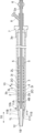
- FIG. 1 is a side view of a chip according to an embodiment.
- FIG. 2 is an axial cross-sectional view of FIG. 1.
- FIG. 3 is a cross-sectional view taken along the line AA in FIG.
- FIG. 4 is a sectional view showing a modification of the cross section of FIG.
- FIG. 5 is a sectional view showing a modification of the cross section of FIG.
- FIG. 6 is an axial cross-sectional view of a chip according to another embodiment.
- FIG. 7 is a sectional view showing a modification of the cross section of FIG.
- FIG. 8 is a sectional view showing a modification of the cross section of FIG.
- FIG. 9 is a side view showing the first member fixed to the inner tube and the second member before being fixed to the first member.
- FIG. 10 is a side view of the medical device according to the embodiment.
- FIG. 11 is an axial cross-sectional view of FIG. 10.
- FIG. 12 is an axial cross-sectional view of a medical
- a chip according to an embodiment of the present invention is a chip used at a distal end of a medical device inserted into a body, and includes a first member including a proximal end of the chip, and a distal end of the first member. and a second member located distally from the end, the first member having a first opposing surface facing the second member, and the first opposing surface being fixed to the second member.
- the first fixed part is fixed to the second member, and the non-fixed part is not fixed to the second member.
- the first opposing surface has the non-fixed part, a gap is formed between the first member and the second member that functions as a buffer part, and the chip becomes partially flexible. , the tip becomes less likely to damage the tissues it comes in contact with in the body. Furthermore, since the first opposing surface has the fixing portion, the first member and the second member are fixed in the distance direction, making it easier to push the tip into the stenosis from the proximal side to the distal side. .
- FIG. 1 is a side view of a chip according to an embodiment.
- FIG. 2 is an axial cross-sectional view of FIG. 1.
- FIG. 3 is a cross-sectional view taken along the line AA in FIG. 4, 5, 7, and 8 are cross-sectional views showing modifications of the cross-section of FIG. 3.
- FIG. 6 is an axial cross-sectional view of a chip according to another embodiment.
- FIG. 9 is a side view showing the first member fixed to the inner tube and the second member before being fixed to the first member.
- FIG. 10 is a side view of the medical device according to the embodiment
- FIG. 11 is a cross-sectional view in the axial direction of FIG. 10.
- FIG. 12 is an axial cross-sectional view of a medical device according to another embodiment.
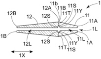
- a chip 1 shown in FIG. 1 is a chip used at the distal end of a medical device inserted into the body.
- the tip 1 is preferably a tip used at the distal end portion 10b of the medical device 10 for transporting the medical device 4 into the body.
- the tip 1 includes a first member 11 including a proximal end 1A of the tip 1, and a second member 12 located distal to the distal end 11b of the first member 11. It has The first member 11 has a first opposing surface 11S that faces the second member 12, and the first opposing surface 11S has a first fixing portion 11T fixed to the second member 12 and a first opposing surface 11S that faces the second member 12. It has a non-fixed portion 11Y that is not fixed.
- the first opposing surface 11S has the non-fixed portion 11Y, a gap is formed between the first member 11 and the second member 12, which functions as a buffer portion. As a result, the tip 1 becomes partially flexible, making it difficult for the tip 1 to damage the tissue it contacts within the body. Furthermore, since the first opposing surface 11S has the first fixing portion 11T, the second member 12 can be easily pushed into the distal side by the first member 11.
- the first member 11 and the second member 12 each extend in the axial direction 1X of the chip 1. This makes it easier to push the chip 1 in the axial direction 1X. Further, it is preferable that the axial direction of the first member 11 and the axial direction of the second member 12 are the same direction.
- the first fixing portion 11T of the first opposing surface 11S only needs to be fixed to the second member 12.
- a method of fixing the first fixing part 11T to the second member 12 for example, a part of the first opposing surface 11S of the first member 11 is brought into contact with the second opposing surface 12S of the second member 12 and fixed by welding.
- a method of fixing a part of the first opposing surface 11S of the first member 11 to the second opposing surface 12S of the second member 12 with an adhesive can be cited.
- the second opposing surface 12S is a surface of the second member 12 that faces the first member 11.
- the first opposing surface 11S is preferably fixed to the second member 12 by welding at the first fixing portion 11T. Since welding improves the fixing strength between the first member 11 and the second member 12, it is possible to make it easier to push the second member 12 distally by the first member 11.
- the longest straight line distance in the axial direction 1X from the first opposing surface 11S to the second opposing surface 12S is preferably 0.1 times or more, and 0.2 times or more the maximum outer diameter of the first member 11. It is more preferable that there be. This makes it easier for the gap between the first member 11 and the second member 12 to function as a buffer.
- the longest linear distance is preferably 0.5 times or less, more preferably 0.4 times or less, and even more preferably 0.3 times or less than the maximum outer diameter of the first member 11. preferable. This makes it easier to push the chip 1 in the axial direction 1X.
- the angle between the outer edge of the first fixing portion 11T and the axial direction 1X is preferably 80 degrees or more and 100 degrees or less, and 85 degrees or more, It is more preferably 95 degrees or less, and even more preferably 88 degrees or more and 92 degrees or less.
- the angle between the outer edge of the first fixing portion 11T and the axial direction 1X is closer to 90 degrees, it is easier to push the second member 12 distally by the first member 11.
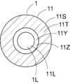
- the first member 11 has a lumen 11L extending from a proximal end 11A to a distal end 11B
- the second member 12 has a lumen 11L extending from a proximal end 12A to a distal end 12B. It is preferable to have a lumen 12L communicating with the lumen 11L. This allows the flexibility of the chip 1 to be improved. Furthermore, a long body such as a guide wire can also be inserted into the inner cavities 11L and 12L.
- the non-fixed part 11Y is preferably located closer to the inner cavity 11L than the first fixed part 11T.
- the gap formed by the non-fixed portion 11Y arranged in this way buffers the force applied from the distal end 1B to the proximal end 1A of the tip 1, making it easier to avoid the tip 1 from penetrating the contact tissue. I can do it.
- the first opposing surface 11S does not have a fixed part fixed to the second member 12 on the side closer to the inner cavity 11L than the non-fixed part 11Y. This forms a gap that communicates with the inner cavity 1L, making it easier to buffer the force applied from the distal end 1B to the proximal end 1A of the tip 1.
- the non-fixed portion 11Y is preferably a groove 11Z extending in the circumferential direction of the inner cavity 11L.
- the groove 11Z extending in the circumferential direction makes it easier to buffer the force applied from the distal end 1B to the proximal end 1A of the tip 1.
- the groove 11Z is preferably V-shaped or U-shaped, more preferably U-shaped. It is preferable that the groove 11Z does not extend in the axial direction 1X. Thereby, the ability of the chip 1 to break through the stenosis can be improved.
- the maximum depth of the groove 11Z is preferably 0.1 times or more, more preferably 0.2 times or more the maximum outer diameter of the first member 11. This makes it easier for the groove 11Z to function as a buffer. On the other hand, the maximum depth of the groove 11Z is preferably 0.4 times or less, more preferably 0.3 times or less, the maximum outer diameter of the first member 11. This makes it easier to push the chip 1 in the axial direction 1X.
- the groove 11Z extends in a part of the circumferential direction and does not extend all the way around the circumferential direction. This makes it easier for the second member 12 to bend slightly toward the groove 11Z when a force is applied in the axial direction 1X, making it easier to avoid the tip 1 sticking into the contact tissue.
- the non-fixed part 11Y has a part located closer to the inner cavity 11L than the first fixed part 11T, and a part not located closer to the inner cavity 11L than the first fixed part 11T. You can leave it there. This makes it easier for the tip 1 to bend in multiple directions, thereby improving the ability to follow the guide wire.
- the first opposing surface 11S may have a plurality of first fixing portions 11T in the circumferential direction.
- the non-fixed portion 11Y may communicate with the inner cavity 1L of the chip 1 and the space outside the chip 1.
- the non-fixed portion 11Y may communicate with the inner cavity 1L of the chip 1 and the space outside the chip 1.
- the non-fixed portion 11Y that communicates with the space and making it easier to break a part of the tip 1, it is possible to further prevent the tip 1 from penetrating the contact tissue.
- the non-fixed portion 11Y communicates with the space outside the chip 1, the non-fixed portion 11Y can also function as a visual marker.
- the first opposing surface 11S preferably does not have a non-fixed part that is not fixed to the second member 12 on the outside of the first fixed part 11T. This makes it easier to prevent the opening portion of the chip 1 from being deformed, such as expanding outward, when the chip 1 is inserted.
- the first opposing surface 11S has a second fixed part 11U fixed to the second member 12, and the second fixed part 11U is larger than the non-fixed part 11Y in the inner cavity 11L. It may be located on the side. This makes it easier to avoid the guide wire from getting caught in the inner cavity 1L of the tip 1.
- the non-fixed part 11Y is located closer to the inner cavity 11L than the first fixed part 11T, and the second fixed part 11U is located closer to the inner cavity 11L than the non-fixed part 11Y. You can leave it there. According to such an arrangement, the gap formed by the non-fixed portion 11Y is closed in the radial direction, so that plastic deformation of the chip 1 can be easily prevented. Although not shown, it is preferable that the non-fixed portion 11Y extends in a part of the circumferential direction and does not extend all the way around the circumferential direction.
- the first opposing surface 11S shown in FIGS. 6 and 7 may further include a non-fixed portion closer to the inner cavity 11L than the second fixed portion 11U. It is preferable that the non-fixed portion is a groove extending in the circumferential direction of the inner cavity 11L. Further, it is preferable that the non-fixed portion extends in a part of the circumferential direction and does not extend all the way around the circumferential direction.
- the angle between the outer edge of the second fixing part 11U and the axial direction 1X is preferably 80 degrees or more and 100 degrees or less, more preferably 85 degrees or more and 95 degrees or less, More preferably, the temperature is 88 degrees or more and 92 degrees or less.
- the angle between the outer edge of the second fixing portion 11U and the axial direction 1X is closer to 90 degrees, it is easier to push the second member 12 distally by the first member 11.
- the first opposing surface 11S includes, in the circumferential direction, a plurality of first fixed portions 11T and a plurality of non-fixed portions 11Y each disposed between the plurality of first fixed portions 11T. You can leave it there. In this way, the first opposing surface 11S may have two or more non-fixed parts. This makes it easier for the tip 1 to bend in multiple directions, thereby improving the ability to follow the guide wire.
- the first member 11 has an enlarged diameter portion whose outer diameter increases toward the distal end 11B of the first member 11. It is preferable that the outer diameter of the expanded diameter portion continuously increases toward the distal end 11B. As a result, the distal side of the first member 11 becomes thicker, making it easier to push the second member 12 toward the distal side.
- the outer edge of the enlarged diameter portion in side view is preferably linear and/or curved, more preferably linear. Note that the first member 11 may have two or more enlarged diameter portions.
- the first member 11 may have a constant diameter portion having a constant outer diameter on the distal side of the enlarged diameter portion. This allows the first member 11 to easily push the second member 12 toward the distal side.
- the length of the first member 11 in the axial direction is preferably longer than the maximum outer diameter of the first member 11. Thereby, the first member 11 can be easily inserted into the narrowed portion.
- the second member 12 preferably has a reduced diameter portion where the outer diameter decreases toward the distal end 12B of the second member 12. It is preferable that the outer diameter of the reduced diameter portion decreases continuously toward the distal end 12B. As a result, the distal side of the second member 12 has a tapered shape, so that the second member 12 can be easily pushed into the narrowed portion.
- the outer edge of the reduced diameter portion in side view is preferably linear and/or curved, more preferably linear. Note that the second member 12 may have two or more reduced diameter portions.
- the angle of inclination of the outer edge of the enlarged diameter portion with respect to the axial direction 1X is preferably larger than the angle of inclination of the outer edge of the reduced diameter portion with respect to the axial direction 1X. This makes it easier to push the first member 11 distally by the second member 12, and also makes it easier to insert the second member 12 into the stenosis.
- the second member 12 includes the distal end 1B of the tip 1. This makes it easier to push the second member 12 into the narrowed portion. Further, it is preferable that the tip 1 does not include any other member distal to the second member 12.
- the second member 12 may have a constant diameter portion having a constant outer diameter on the proximal side of the reduced diameter portion. This makes it easier to push the second member 12 toward the distal side.
- the length of the second member 12 in the axial direction is preferably longer than the length of the first member 11 in the axial direction. Thereby, the force applied to the entire chip 1 is easily damped by the gap between the first member 11 and the second member 12.
- the axial length of the first member 11 is the axial length from the proximal end 11A to the distal end 11B of the first member 11, and the axial length of the second member 12 is the axial length of the second member 11. It is the length in the axial direction from the proximal end 12A to the distal end 12B of No. 12.
- the length of the second member 12 in the axial direction is preferably longer than the maximum outer diameter of the second member 12. Thereby, the second member 12 can be easily inserted into the narrowed portion.
- the first member 11 contains a first resin
- the second member 12 contains a second resin having a melting point that is the same as or lower than the melting point of the first resin.
- the first member 11 is made of a first resin
- the second member 12 is made of a second resin having a melting point that is the same as or lower than the melting point of the first resin.
- the melting point of the second member 12 is preferably the same as or lower than the melting point of the first member 11, and more preferably lower than the melting point of the first member 11.
- the melting point can be measured, for example, by DSC, and it is preferable that the temperature at which the top of the endothermic peak of the DSC curve appears is determined as the melting point.
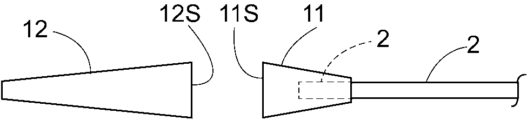
- the first member 11 is preferably fixed to the second member 12, for example, by the following method. Specifically, as shown in FIG. 9, after inserting the distal end 2b of the inner tube 2 of the medical device into the inner cavity 11L of the first member 11 and fixing the first member 11 to the inner tube 2, the first member 11 is fixed to the inner tube 2. It is preferable to fix the first member 11 to the second member 12 after bringing at least a portion of the first opposing surface 11S of the first member 11 into contact with the second opposing surface 12S of the second member 12. This reduces the thermal stress during manufacturing on the fixed portion of the first member 11 and second member 12, compared to the case where the first member 11 is fixed to the second member 12 and then the first member 11 is fixed to the inner tube 2. etc., it is possible to easily maintain the fixing strength of the fixing portion of the second member 12 of the first member 11.
- the contact portion between the first member 11 and the second member 12 can be formed by welding from the outside with hot air.
- the chip 1 shown in FIG. 4 can be formed, for example, by inserting a partially cooled core material into the inner cavity 1L and welding it from the outside with hot air in the same manner as described above.
- the chip 1 shown in FIG. 5 is formed by, for example, inserting a cooled core material into the inner cavity 1L and applying hot air partially to the contact portion between the first member 11 and the second member 12 in the radial direction. be able to.
- the core material is heated to a temperature within the melting point of the chip 1 +10°C, and the heating is preferably performed by external hot air at the same temperature for 1 second or more and 5 seconds or less. It can be formed by performing the process for a while.
- the chip 1 shown in FIG. 8 can be formed by partially applying hot air to the contact portion between the first member 11 and the second member 12 in the radial direction from the outside.
- the first member 11 and the second member 12 may be fixed with an adhesive.
- the adhesive include hot melt adhesives, moisture curing adhesives, ultraviolet curable adhesives, and two-component curing adhesives. Among these, hot-melt adhesives and moisture-curing adhesives are preferred.
- adhesives include acrylic adhesives, polyurethane adhesives, cyanoacrylate adhesives, silicone adhesives, vinyl acetate adhesives, and epoxy adhesives. These may be used alone or in combination of two or more.
- the first member 11 and the second member 12 each preferably contain resin, and are more preferably made of resin.
- the resin is a thermoplastic resin.
- the resins include polyolefin resins such as polyethylene and polypropylene, polyamide resins such as polyamide and polyether polyamide, polyester resins such as polyethylene terephthalate and polybutylene terephthalate, polytetrafluoroethylene, and tetrafluoroethylene/hexafluoropropylene copolymers.
- Fluororesins such as combinations, polyvinyl chloride resins, silicone resins, polyurethane resins, ethylene-vinyl acetate copolymer resins, polyetheretherketone resins, polyetherimide resins, polyolefin elastomers, polyamide elastomers, polyester elastomers, polyurethane elastomers, or these Preferably, it is a mixture of. These may be used alone or in combination of two or more.
- the first member 11 and the second member 12 may each contain additives such as a hydrolysis inhibitor, a flame retardant, a filler, and a crosslinking agent.
- the first member 11 and the second member 12 may contain the same resin, but preferably contain different resins.
- the first member 11 and the second member 12 may each have a multilayer structure, and each layer may contain a different resin or the same resin.
- the first member 11 and the second member 12 can be manufactured using the above resins, for example, by injection molding or extrusion molding.
- the chip 1 preferably contains the above resin, and is preferably made of the above resin.
- the chip 1 may have X-ray opaque particles and/or X-ray opaque marker bands kneaded with the resin.
- Examples of the X-ray opaque particles include particles made of an X-ray opaque substance.
- Examples of the radiopaque marker band include marker bands made of a radiopaque substance.
- the radiopaque material can be gold, platinum, silver, tungsten, tantalum, iridium, palladium, rhenium, rhodium, tin, nickel, titanium, alloys thereof, barium sulfate, bismuth compounds, tungsten compounds, or mixtures thereof. It is preferable that there be.
- the alloy is a gold-palladium alloy, a platinum-iridium alloy, a NiTiPd alloy, a NiTiAu alloy, a NiTi alloy or a mixture thereof. These may be used alone or in combination of two or more.
- the medical device 10 is a medical device for transporting a medical device 4 into the body, and includes an inner tube 2 and at least one portion of the inner tube 2 in the inner cavity 3L. an outer tube 3 in which a part is arranged; a tip 1 fixed to at least a part of the distal end 2b of the inner tube 2; an outer surface 2O of the distal end 2b of the inner tube 2; 3 and an inner surface 3I of the medical device 4.
- the inner tube 2 has a lumen 2L, and the lumen 2L is configured so that a guide wire can be inserted therein. Thereby, the medical device 4 and the like can be delivered to the stenosis by moving the inner tube 2 and the like along the guide wire.
- the distal end 2b of the inner tube 2 is fixed to the inner surface of the tip 1. Therefore, it is preferable that a part of the inner cavity 1L of the tip 1 has a diameter equal to or larger than the outer diameter of the inner tube 2 so that the distal end 2b of the inner tube 2 can be accommodated therein. Furthermore, the other portion of the lumen 1L of the tip 1 may have a diameter equal to or less than the diameter of the lumen 2L of the inner tube 2.
- the chip 1 and the inner tube 2 may be directly fixed by thermal welding or the like, or may be indirectly fixed using an adhesive or the like.
- the distal end of the inner tube 2 is preferably located closer to the proximal side than the distal end 11B of the first member 11 of the tip 1. Thereby, the force applied to the second member 12 can be easily damped by the gap between the first member 11 and the second member 12.
- first member 11 is fixed to the inner tube 2 and the second member 12 is not fixed to the inner tube 2. Thereby, the force applied to the second member 12 can be easily buffered by the gap between the first member 11 and the second member 12.
- the inner tube 2 is disposed in the inner cavity 3L of the outer tube 3.
- the distal end of the inner tube 2 is located more distally than the distal end of the outer tube 3. This can prevent kinks and reduce rigidity differences.
- the proximal portion of the inner tube 2 is detachably fixed directly or indirectly to the proximal portion of the outer tube 3.
- the operations of the medical device 4 include operations such as expansion, deployment, and detachment. Note that the above-mentioned attachment and detachment can be performed via an outer handle member 7, which will be described later.
- the medical device 4 When the medical device 4 is a self-expanding type described below, it is placed between the outer surface 2O of the distal end 2b of the inner tube 2 and the inner surface 3I of the outer tube 3, so that the medical device 4 can maintain a contracted state. It can be maintained and expanded by moving distally from the outer tube 3. Furthermore, the tip 1 can avoid malfunctions such as the medical device 4 moving distally from the outer tube 3 and being deployed before the medical device 4 is placed in the stenotic region.
- the distal end 4B of the medical device 4 is located closer to the proximal side than the non-fixed portion 11Y of the first opposing surface 11S. Thereby, damage to the distal end 4B of the medical device 4 due to movement of the tip 1 during delivery can be easily avoided.
- the distal end 4B of the medical device 4 is located more distally than the proximal end 11A of the first member 11. Thereby, the movement of the medical device 4 in the axial direction can be reduced and positional deviation can be prevented. Furthermore, by overlapping the distal end of the medical device 4 and the tip 1, it is possible to reduce the difference in rigidity and make it easier to prevent kinks.
- the inner tube 2 preferably has an inner handle member 6 at the proximal end 2a.
- the outer tube 3 also preferably has an outer handle member 7 at the proximal end 3a.
- the pusher member 5 is fixed to the outer surface 2O of the inner tube 2.
- the pusher member 5 allows the medical device 4 to be pushed out easily. It is preferable that the pusher member 5 is a tubular body.
- the outer tube 3 may be movable in the axial direction.
- the medical device 10 includes an outermost tube 3X in which at least a portion of the outer tube 3 is disposed in the inner lumen 3XL, and a line in which the distal end 3Yb is fixed to the proximal end 3a of the outer tube 3. It is preferable to have a shaped member 3Y. Furthermore, it is more preferable that the outermost tube 3X and the inner tube 2 have inner handle members 6 at the proximal end 3Xa and the proximal end 2a.
- the linear member 3Y may be a rotating body such as a thumbwheel, or may be wound around a rotating body.
- the outer handle member 7 may have a flush lumen 8. Thereby, a desired liquid can be injected from the flushing lumen 8 into the lumen 3L of the outer tube 3.
- the outer tube 3 may have an X-ray opaque region at the distal end 3b. Thereby, the position of the distal end portion 3b of the outer tube 3 can be grasped.
- the radiopaque region is preferably located more proximally than the distal end 11B of the first member 11 of the chip 1 and more distally than the proximal end 11A. Thereby, the outer tube 3 can increase the rigidity of the distal end portion 3b.
- the radiopaque region may contain radiopaque particles and/or radiopaque marker bands intermixed with the resin. Examples of the X-ray opaque particles include particles made of an X-ray opaque substance. Examples of the radiopaque marker band include marker bands made of a radiopaque substance. Regarding the X-ray opaque substance, refer to the description of the X-ray opaque substance in the chip 1.
- the inner tube 2, outer tube 3, pusher member 5, and outermost tube 3X each contain resin.
- the resin includes polyethylene, polyimide, polyether block amide, polyamide, polyurethane, polyester, silicone, polyamide elastomer, fluororesin such as PTFE, PFA, or a mixture thereof. These may be used alone or in combination of two or more.
- the resin may also contain additives such as hydrolysis inhibitors, flame retardants, fillers, and crosslinking agents.
- the inner tube 2, the outer tube 3, and the outermost tube 3X may each have an inner layer and an outer layer.
- the inner tube 2, the outer tube 3, and the outermost tube 3X may have a tubular reinforcing member.
- Examples of the reinforcing member include a spiral wire rod, a braided wire rod, and the like.
- the wire include stainless steel, titanium, cobalt chromium alloy, Ni-Ti, tungsten, polyarylate fiber, aramid fiber, ultra-high molecular weight polyethylene fiber, PBO fiber, carbon fiber, and mixtures thereof.
- examples of the material of the linear member 3Y include stainless steel, titanium, cobalt chromium alloy, Ni--Ti, and tungsten. These may be used alone or in combination of two or more.
- the medical device 4 includes an X-ray opaque substance. Thereby, the position of the medical device 4 can be confirmed under X-ray fluoroscopy.
- the X-ray opaque substance refer to the description of the X-ray opaque substance in the chip 1.
- the medical device 4 preferably contains resin and/or metal, more preferably contains metal, and still more preferably consists of metal.
- the medical device 4 is a medical tubular body.
- the medical tubular body is a stent, stent graft, obturator, infusion catheter, or prosthetic valve, more preferably a stent.
- Stents include, for example, coiled stents made of linear resin and/or metal, stents made by cutting out a tube with a laser, and stents made by cutting out a sheet with a laser and then winding it into a cylindrical shape and laser welding it. , a stent made by welding linear bodies together using a laser, and a stent made by weaving a plurality of linear resins and/or metals.
- the stent is preferably a balloon-expandable stent that expands using a balloon mounted on the stent, or a self-expanding stent that expands by itself by removing an external member that inhibits the expansion of the stent. More preferred.
- the medical device 4 may be a stent having a shape other than a tubular shape, a stent graft having a shape other than a tubular shape, an obturator having a shape other than a tubular shape, or the like. Examples of shapes other than tubular include spherical.
- the medical device 4 may be any device as long as it can be used in conjunction with the inner tube 2, outer tube 3, and tip 1, and may be, for example, a balloon, a basket, a snare, or an obturator.
- the medical device 10 is preferably a medical tubular body transport device that transports the medical tubular body 4 into the body.
- the medical device 10 can be used for strictures occurring in the coronary arteries of the heart, other blood vessels, the trachea, the esophagus, the bile ducts, the urethra, and the like.
Landscapes
- Health & Medical Sciences (AREA)
- Engineering & Computer Science (AREA)
- Life Sciences & Earth Sciences (AREA)
- Biomedical Technology (AREA)
- Veterinary Medicine (AREA)
- Animal Behavior & Ethology (AREA)
- Public Health (AREA)
- Heart & Thoracic Surgery (AREA)
- General Health & Medical Sciences (AREA)
- Hematology (AREA)
- Anesthesiology (AREA)
- Pulmonology (AREA)
- Biophysics (AREA)
- Cardiology (AREA)
- Oral & Maxillofacial Surgery (AREA)
- Transplantation (AREA)
- Vascular Medicine (AREA)
- Media Introduction/Drainage Providing Device (AREA)
Abstract
The purpose of the present invention is to provide a chip which is unlikely to damage a tissue contacted thereby and which is easily inserted into a narrow site. This chip is used at a distal end of a medical device to be inserted into the body. The chip has: a first member that includes the proximal end of the chip; and a second member that is positioned more toward the distal side than the distal end of the first member. The first member has a first opposing surface opposing the second member. The first opposing surface has a first fixed section which is fixed to the second member, and a non-fixed section which is not fixed to the second member.
Description
本発明は、体内に挿入される医療用装置の遠位端部に用いられるチップ、及び医療用装置に関する。
The present invention relates to a chip used at the distal end of a medical device inserted into the body, and a medical device.
従来、狭窄した消化器管や血管等の狭窄部位にカテーテルを挿入するか又は通過させる場合があり、カテーテルの先端にはチップが設けられていた。先端チップを有するカテーテルとして、例えば特許文献1には、内層と、内層を覆う補強体と、補強体を覆う外層とを有するチューブ体と、チューブ体の先端に設けられた金属から成る管状の先端チップとを備え、先端チップにはスリットが形成されており、先端チップの外周面には外側被覆が設けられ、且つ、外側被覆がスリットの内部に入り込んでいるカテーテルが開示されている。
Conventionally, a catheter is sometimes inserted or passed through a narrowed site such as a narrowed gastrointestinal tract or blood vessel, and a tip is provided at the tip of the catheter. As a catheter having a distal tip, for example, Patent Document 1 discloses a tube body having an inner layer, a reinforcing body covering the inner layer, and an outer layer covering the reinforcing body, and a tubular tip made of metal provided at the distal end of the tube body. A catheter is disclosed which includes a tip, a slit is formed in the distal tip, an outer coating is provided on the outer peripheral surface of the distal tip, and the outer coating is inserted into the inside of the slit.
特許文献1の先端チップには、全体的に曲り易くするために軸方向に延在するらせん状のスリットが設けられているが、外側被覆がスリットの内部に入り込んでいるため、外側被覆の素材によってはチップがほとんど曲らない可能性があった。また近年ではステントデリバリーカテーテルを用いて狭窄部位にステントを留置する処置が行われることが多く、特にステントデリバリーカテーテルの先端チップには、接触組織の損傷回避等の安全性の向上と、狭窄部位への挿入のし易さの向上が求められていた。本発明は上記の様な問題に着目してなされたものであって、その目的は、接触組織を損傷し難く、且つ狭窄部位に挿入し易いチップを提供することにある。またその他の目的は、接触組織を損傷し難く、且つ狭窄部位に挿入し易い医療用装置を提供することにある。
The distal tip of Patent Document 1 is provided with a spiral slit extending in the axial direction in order to make the tip easier to bend as a whole, but since the outer covering is inside the slit, the material of the outer covering is Depending on the situation, there was a possibility that the tip would hardly bend. In addition, in recent years, a stent delivery catheter is often used to place a stent in a stenotic area. There was a need to improve the ease of insertion. The present invention has been made in view of the above-mentioned problems, and its purpose is to provide a tip that is less likely to damage contact tissue and that is easier to insert into a stenotic site. Another object is to provide a medical device that is less likely to damage contact tissues and that is easier to insert into a stenotic site.
上記課題を解決することのできた本発明の実施の形態に係る医療用装置の遠位端部に用いられるチップは、以下の通りである。
[1]体内に挿入される医療用装置の遠位端部に用いられるチップであって、
前記チップの近位端を含む第1部材と、
前記第1部材の遠位端部よりも遠位側に位置する第2部材とを有し、
前記第1部材は、前記第2部材に対向する第1対向面を有し、前記第1対向面は、前記第2部材に固定されている第1固定部と、前記第2部材に固定されていない非固定部とを有しているチップ。 The chip used in the distal end of the medical device according to the embodiment of the present invention, which can solve the above problems, is as follows.
[1] A chip used at the distal end of a medical device inserted into the body,
a first member including a proximal end of the tip;
a second member located on the distal side of the distal end of the first member;
The first member has a first opposing surface facing the second member, and the first opposing surface includes a first fixing part fixed to the second member and a first fixing part fixed to the second member. A chip that does not have a non-fixed part.
上記の通り、第1対向面が非固定部を有していることにより、第1部材と第2部材との間に緩衝部として機能する間隙が形成されてチップが部分的に柔軟になるため、チップは体内において接触組織を損傷し難くなる。更に、第1対向面が固定部を有していることにより、第1部材と第2部材が遠近方向に固定されて、チップを近位側から遠位側に向けて狭窄部内に押し込み易くなる。
As mentioned above, since the first opposing surface has the non-fixed part, a gap is formed between the first member and the second member that functions as a buffer part, and the chip becomes partially flexible. , the tip becomes less likely to damage the tissues it comes in contact with in the body. Furthermore, since the first opposing surface has the fixing portion, the first member and the second member are fixed in the distance direction, making it easier to push the tip into the stenosis from the proximal side to the distal side. .
本発明の実施の形態に係るチップは、以下の[2]~[12]のいずれかであることが好ましい。
[2]前記第1部材は、近位端から遠位端へ延在する内腔を有し、
前記第2部材は、近位端から遠位端へ延在し前記内腔に連通する内腔を有している[1]に記載のチップ。
[3]前記非固定部は、前記第1固定部よりも前記内腔側に位置している[2]に記載のチップ。
[4]前記第1対向面は、前記第2部材に固定されている第2固定部を有し、
前記第2固定部は、前記非固定部よりも前記内腔側に位置している[2]または[3]に記載のチップ。
[5]前記第1対向面は、前記非固定部よりも前記内腔側において、前記第2部材に固定されている固定部を有していない[2]または[3]に記載のチップ。
[6]前記非固定部は、前記内腔の周方向に延在する溝である[2]、[3]、または[5]に記載のチップ。
[7]前記溝は、前記周方向の一部において延在しており、前記周方向の全周にわたって延在していない[6]に記載のチップ。
[8]前記第1対向面は、前記第1固定部よりも外側において、前記第2部材に固定されていない非固定部を有していない[1]~[7]のいずれかに記載のチップ。
[9]前記第1部材は、前記第1部材の前記遠位端に向かって外径が大きくなっている拡径部を有している[1]~[8]のいずれかに記載のチップ。
[10]前記第1部材は第1樹脂を含み、
前記第2部材は、前記第1樹脂の融点と同じか又は前記第1樹脂の融点よりも低い融点を有する第2樹脂を含む[1]~[9]のいずれかに記載のチップ。
[11]前記第1対向面は、前記第1固定部において、溶着により前記第2部材に固定されている[1]~[10]のいずれかに記載のチップ。
[12]前記医療用装置は、医療用管状体を体内に搬送する医療用管状体搬送装置である[1]~[11]のいずれかに記載のチップ。 The chip according to the embodiment of the present invention is preferably one of the following [2] to [12].
[2] The first member has a lumen extending from the proximal end to the distal end,
The chip according to [1], wherein the second member has a lumen extending from the proximal end to the distal end and communicating with the lumen.
[3] The chip according to [2], wherein the non-fixed portion is located closer to the lumen than the first fixed portion.
[4] The first opposing surface has a second fixing part fixed to the second member,
The chip according to [2] or [3], wherein the second fixed part is located closer to the lumen than the non-fixed part.
[5] The chip according to [2] or [3], wherein the first opposing surface does not have a fixing part fixed to the second member on the lumen side relative to the non-fixing part.
[6] The chip according to [2], [3], or [5], wherein the non-fixed portion is a groove extending in the circumferential direction of the inner cavity.
[7] The chip according to [6], wherein the groove extends in a part of the circumferential direction and does not extend all the way around the circumferential direction.
[8] The first opposing surface according to any one of [1] to [7] does not have a non-fixed part that is not fixed to the second member on the outside of the first fixed part. Chip.
[9] The chip according to any one of [1] to [8], wherein the first member has an enlarged diameter portion whose outer diameter increases toward the distal end of the first member. .
[10] The first member includes a first resin,
The chip according to any one of [1] to [9], wherein the second member includes a second resin having a melting point that is the same as or lower than the melting point of the first resin.
[11] The chip according to any one of [1] to [10], wherein the first opposing surface is fixed to the second member by welding at the first fixing portion.
[12] The chip according to any one of [1] to [11], wherein the medical device is a medical tubular body transport device that transports a medical tubular body into the body.
上記課題を解決することのできた本発明の実施の形態に係る医療用装置は、以下の[13]の通りであり、[14]~[16]のいずれかであることが好ましい。
[13]体内に挿入される医療用装置であって、
内側チューブと、
内腔に前記内側チューブの少なくとも一部が配置されている外側チューブと、
前記内側チューブの遠位端部の少なくとも一部に固定されている[1]~[12]のいずれかに記載のチップと、
前記内側チューブの前記遠位端部の外側面と、前記外側チューブの内側面との間に配置されている医療用具とを有している医療用装置。
[14]前記医療用具の遠位端は、前記第1対向面の前記非固定部よりも近位側に位置する[13]に記載の医療用装置。
[15]前記第1部材は、前記内側チューブに固定されており、前記第2部材は、前記内側チューブに固定されていない[13]または[14]に記載の医療用装置。
[16]前記医療用具は、医療用管状体であり、前記医療用管状体を体内に搬送する医療用管状体搬送装置である[13]~[15]のいずれかに記載の医療用装置。 A medical device according to an embodiment of the present invention that can solve the above problem is as shown in [13] below, and preferably any one of [14] to [16].
[13] A medical device inserted into the body,
an inner tube;
an outer tube having at least a portion of the inner tube disposed in a lumen;
The chip according to any one of [1] to [12], which is fixed to at least a portion of the distal end of the inner tube;
A medical device having a medical device disposed between an outer surface of the distal end of the inner tube and an inner surface of the outer tube.
[14] The medical device according to [13], wherein the distal end of the medical device is located closer to the non-fixed portion of the first opposing surface.
[15] The medical device according to [13] or [14], wherein the first member is fixed to the inner tube, and the second member is not fixed to the inner tube.
[16] The medical device according to any one of [13] to [15], wherein the medical device is a medical tubular body, and is a medical tubular body transport device that transports the medical tubular body into the body.
本発明によれば、上記構成により、接触組織を損傷し難く、且つ狭窄部位に挿入し易いチップを提供することができる。また本発明によれば、接触組織を損傷し難く、且つ狭窄部位に挿入し易い医療用装置を提供することができる。
According to the present invention, with the above configuration, it is possible to provide a tip that is difficult to damage contact tissue and that is easy to insert into a stenosis site. Further, according to the present invention, it is possible to provide a medical device that does not easily damage contact tissues and is easy to insert into a stenotic site.
以下では、下記実施の形態に基づき本発明をより具体的に説明するが、本発明はもとより下記実施の形態によって制限を受けるものではなく、前・後記の趣旨に適合し得る範囲で適当に変更を加えて実施することも勿論可能であり、それらはいずれも本発明の技術的範囲に包含される。なお、各図面において、便宜上、部材符号等を省略する場合もあるが、かかる場合、明細書や他の図面を参照するものとする。また、図面における種々部材の寸法は、本発明の特徴の理解に資することを優先しているため、実際の寸法とは異なる場合がある。
In the following, the present invention will be explained in more detail based on the following embodiments, but the present invention is not limited by the following embodiments, and may be modified as appropriate within the scope that fits the spirit of the above and below. Of course, it is also possible to implement in addition, and all of them are included in the technical scope of the present invention. In addition, in each drawing, member numbers etc. may be omitted for convenience, but in such a case, the specification and other drawings shall be referred to. Further, the dimensions of various members in the drawings are given priority to help understanding the features of the present invention, and therefore may differ from actual dimensions.
本発明の実施の形態に係るチップは、体内に挿入される医療用装置の遠位端部に用いられるチップであって、チップの近位端を含む第1部材と、第1部材の遠位端部よりも遠位側に位置する第2部材とを有し、第1部材は、第2部材に対向する第1対向面を有し、第1対向面は、第2部材に固定されている第1固定部と、第2部材に固定されていない非固定部とを有している。
A chip according to an embodiment of the present invention is a chip used at a distal end of a medical device inserted into a body, and includes a first member including a proximal end of the chip, and a distal end of the first member. and a second member located distally from the end, the first member having a first opposing surface facing the second member, and the first opposing surface being fixed to the second member. The first fixed part is fixed to the second member, and the non-fixed part is not fixed to the second member.
上記の通り、第1対向面が非固定部を有していることにより、第1部材と第2部材との間に緩衝部として機能する間隙が形成されてチップが部分的に柔軟になるため、チップは体内において接触組織を損傷し難くなる。更に、第1対向面が固定部を有していることにより、第1部材と第2部材が遠近方向に固定されて、チップを近位側から遠位側に向けて狭窄部内に押し込み易くなる。
As mentioned above, since the first opposing surface has the non-fixed part, a gap is formed between the first member and the second member that functions as a buffer part, and the chip becomes partially flexible. , the tip becomes less likely to damage the tissues it comes in contact with in the body. Furthermore, since the first opposing surface has the fixing portion, the first member and the second member are fixed in the distance direction, making it easier to push the tip into the stenosis from the proximal side to the distal side. .
以下では、図1~図12を参照しながら、実施の形態に係るチップ、及び実施の形態に係る医療用装置の順に説明する。図1は、実施の形態に係るチップの側面図である。図2は、図1の軸方向の断面図である。図3は、図1のA-A断面を示す断面図である。図4、5、7、8は、図3の断面の変形例を示す断面図である。図6は、他の実施の形態に係るチップの軸方向の断面図である。図9は、内側チューブに固定された第1部材と、第1部材に固定される前の第2部材を示す側面図である。図10は、実施の形態に係る医療用装置の側面図であり、図11は、図10の軸方向の断面図である。図12は、他の実施の形態に係る医療用装置の軸方向の断面図である。
Hereinafter, a chip according to an embodiment and a medical device according to an embodiment will be explained in this order with reference to FIGS. 1 to 12. FIG. 1 is a side view of a chip according to an embodiment. FIG. 2 is an axial cross-sectional view of FIG. 1. FIG. FIG. 3 is a cross-sectional view taken along the line AA in FIG. 4, 5, 7, and 8 are cross-sectional views showing modifications of the cross-section of FIG. 3. FIG. 6 is an axial cross-sectional view of a chip according to another embodiment. FIG. 9 is a side view showing the first member fixed to the inner tube and the second member before being fixed to the first member. FIG. 10 is a side view of the medical device according to the embodiment, and FIG. 11 is a cross-sectional view in the axial direction of FIG. 10. FIG. 12 is an axial cross-sectional view of a medical device according to another embodiment.
図1に示すチップ1は、体内に挿入される医療用装置の遠位端部に用いられるチップである。例えば図10~図12に示すように、チップ1は、医療用具4を体内に搬送する医療用装置10の遠位端部10bに用いられるチップであることが好ましい。
A chip 1 shown in FIG. 1 is a chip used at the distal end of a medical device inserted into the body. For example, as shown in FIGS. 10 to 12, the tip 1 is preferably a tip used at the distal end portion 10b of the medical device 10 for transporting the medical device 4 into the body.
図1~図3に示す通り、チップ1は、チップ1の近位端1Aを含む第1部材11と、第1部材11の遠位端部11bよりも遠位側に位置する第2部材12とを有している。第1部材11は、第2部材12に対向する第1対向面11Sを有し、第1対向面11Sは、第2部材12に固定されている第1固定部11Tと、第2部材12に固定されていない非固定部11Yとを有している。
As shown in FIGS. 1 to 3, the tip 1 includes a first member 11 including a proximal end 1A of the tip 1, and a second member 12 located distal to the distal end 11b of the first member 11. It has The first member 11 has a first opposing surface 11S that faces the second member 12, and the first opposing surface 11S has a first fixing portion 11T fixed to the second member 12 and a first opposing surface 11S that faces the second member 12. It has a non-fixed portion 11Y that is not fixed.
第1対向面11Sが非固定部11Yを有していることにより、第1部材11と第2部材12との間に緩衝部として機能する間隙が形成される。その結果、チップ1が部分的に柔軟になるため、チップ1は体内において接触組織を損傷し難くなる。更に、第1対向面11Sが第1固定部11Tを有していることにより、第1部材11により第2部材12を遠位側に押し込み易くすることができる。
Since the first opposing surface 11S has the non-fixed portion 11Y, a gap is formed between the first member 11 and the second member 12, which functions as a buffer portion. As a result, the tip 1 becomes partially flexible, making it difficult for the tip 1 to damage the tissue it contacts within the body. Furthermore, since the first opposing surface 11S has the first fixing portion 11T, the second member 12 can be easily pushed into the distal side by the first member 11.
図1、図2に示す通り、第1部材11と第2部材12は、それぞれチップ1の軸方向1Xに延在していることが好ましい。これによりチップ1を軸方向1Xに押し込み易くすることができる。また第1部材11の軸方向と、第2部材12の軸方向は同一方向であることが好ましい。
As shown in FIGS. 1 and 2, it is preferable that the first member 11 and the second member 12 each extend in the axial direction 1X of the chip 1. This makes it easier to push the chip 1 in the axial direction 1X. Further, it is preferable that the axial direction of the first member 11 and the axial direction of the second member 12 are the same direction.
第1対向面11Sの第1固定部11Tは、第2部材12に固定されていればよい。第1固定部11Tを第2部材12に固定する方法としては、例えば、第1部材11の第1対向面11Sの一部を第2部材12の第2対向面12Sに接触、溶着して固定する方法、第1部材11の第1対向面11Sの一部を接着剤により第2部材12の第2対向面12Sに固定する方法が挙げられる。第2対向面12Sは、第2部材12のうち第1部材11に対向する面である。
The first fixing portion 11T of the first opposing surface 11S only needs to be fixed to the second member 12. As a method of fixing the first fixing part 11T to the second member 12, for example, a part of the first opposing surface 11S of the first member 11 is brought into contact with the second opposing surface 12S of the second member 12 and fixed by welding. A method of fixing a part of the first opposing surface 11S of the first member 11 to the second opposing surface 12S of the second member 12 with an adhesive can be cited. The second opposing surface 12S is a surface of the second member 12 that faces the first member 11.
第1対向面11Sは、第1固定部11Tにおいて、溶着により第2部材12に固定されていることが好ましい。溶着によれば第1部材11と第2部材12の固定強度が向上するため、第1部材11により第2部材12を遠位側に押し込み易くすることができる。
The first opposing surface 11S is preferably fixed to the second member 12 by welding at the first fixing portion 11T. Since welding improves the fixing strength between the first member 11 and the second member 12, it is possible to make it easier to push the second member 12 distally by the first member 11.
第1対向面11Sから第2対向面12Sに至るまでの軸方向1Xにおける最長直線距離は、第1部材11の最大外径の0.1倍以上であることが好ましく、0.2倍以上であることがより好ましい。これにより、第1部材11と第2部材12との間の間隙が緩衝部として機能し易くなる。一方、当該最長直線距離は、第1部材11の最大外径の0.5倍以下であることが好ましく、0.4倍以下であることがより好ましく、0.3倍以下であることが更に好ましい。これにより、チップ1を軸方向1Xに押し込み易くすることができる。
The longest straight line distance in the axial direction 1X from the first opposing surface 11S to the second opposing surface 12S is preferably 0.1 times or more, and 0.2 times or more the maximum outer diameter of the first member 11. It is more preferable that there be. This makes it easier for the gap between the first member 11 and the second member 12 to function as a buffer. On the other hand, the longest linear distance is preferably 0.5 times or less, more preferably 0.4 times or less, and even more preferably 0.3 times or less than the maximum outer diameter of the first member 11. preferable. This makes it easier to push the chip 1 in the axial direction 1X.
図2に示す通り、チップ1の軸方向1Xの断面において、第1固定部11Tの外縁と軸方向1Xとのなす角度は、80度以上、100度以下であることが好ましく、85度以上、95度以下であることがより好ましく、88度以上、92度以下であることが更に好ましい。第1固定部11Tの外縁と軸方向1Xとのなす角度が90度に近い方が第1部材11により第2部材12を遠位側に押し込み易くすることができる。
As shown in FIG. 2, in the cross section of the chip 1 in the axial direction 1X, the angle between the outer edge of the first fixing portion 11T and the axial direction 1X is preferably 80 degrees or more and 100 degrees or less, and 85 degrees or more, It is more preferably 95 degrees or less, and even more preferably 88 degrees or more and 92 degrees or less. When the angle between the outer edge of the first fixing portion 11T and the axial direction 1X is closer to 90 degrees, it is easier to push the second member 12 distally by the first member 11.
図2に示す通り、第1部材11は、近位端11Aから遠位端11Bへ延在する内腔11Lを有し、第2部材12は、近位端12Aから遠位端12Bへ延在し内腔11Lに連通する内腔12Lを有していることが好ましい。これによりチップ1の柔軟性を向上することができる。更にガイドワイヤー等の長尺体を内腔11L、12Lに挿入することもできる。
As shown in FIG. 2, the first member 11 has a lumen 11L extending from a proximal end 11A to a distal end 11B, and the second member 12 has a lumen 11L extending from a proximal end 12A to a distal end 12B. It is preferable to have a lumen 12L communicating with the lumen 11L. This allows the flexibility of the chip 1 to be improved. Furthermore, a long body such as a guide wire can also be inserted into the inner cavities 11L and 12L.
図2、図3に示す通り、非固定部11Yは、第1固定部11Tよりも内腔11L側に位置していることが好ましい。このような配置の非固定部11Yにより形成される間隙は、チップ1の遠位端1Bから近位端1Aにかかる力を緩衝して、チップ1の接触組織への突き刺さりを回避し易くすることができる。
As shown in FIGS. 2 and 3, the non-fixed part 11Y is preferably located closer to the inner cavity 11L than the first fixed part 11T. The gap formed by the non-fixed portion 11Y arranged in this way buffers the force applied from the distal end 1B to the proximal end 1A of the tip 1, making it easier to avoid the tip 1 from penetrating the contact tissue. I can do it.
図2、図3に示す通り、第1対向面11Sは、非固定部11Yよりも内腔11L側において、第2部材12に固定されている固定部を有していないことが好ましい。これにより、内腔1Lと連通する間隙が形成されるため、チップ1の遠位端1Bから近位端1Aにかかる力をより一層、緩衝し易くすることができる。
As shown in FIGS. 2 and 3, it is preferable that the first opposing surface 11S does not have a fixed part fixed to the second member 12 on the side closer to the inner cavity 11L than the non-fixed part 11Y. This forms a gap that communicates with the inner cavity 1L, making it easier to buffer the force applied from the distal end 1B to the proximal end 1A of the tip 1.
図3に示す通り、非固定部11Yは、内腔11Lの周方向に延在する溝11Zであることが好ましい。周方向に延在する溝11Zにより、チップ1の遠位端1Bから近位端1Aにかかる力をより一層、緩衝し易くすることができる。軸方向1Xの断面において、溝11Zは、V字状またはU字状であることが好ましく、U字状であることがより好ましい。溝11Zは、軸方向1Xに延在していないことが好ましい。これにより、チップ1の狭窄突破性を向上することができる。
As shown in FIG. 3, the non-fixed portion 11Y is preferably a groove 11Z extending in the circumferential direction of the inner cavity 11L. The groove 11Z extending in the circumferential direction makes it easier to buffer the force applied from the distal end 1B to the proximal end 1A of the tip 1. In the cross section in the axial direction 1X, the groove 11Z is preferably V-shaped or U-shaped, more preferably U-shaped. It is preferable that the groove 11Z does not extend in the axial direction 1X. Thereby, the ability of the chip 1 to break through the stenosis can be improved.
溝11Zの最大深さは、第1部材11の最大外径の0.1倍以上であることが好ましく、0.2倍以上であることがより好ましい。これにより、溝11Zが緩衝部として機能し易くなる。一方、溝11Zの最大深さは、第1部材11の最大外径の0.4倍以下であることが好ましく、0.3倍以下であることがより好ましい。これにより、チップ1を軸方向1Xに押し込み易くすることができる。
The maximum depth of the groove 11Z is preferably 0.1 times or more, more preferably 0.2 times or more the maximum outer diameter of the first member 11. This makes it easier for the groove 11Z to function as a buffer. On the other hand, the maximum depth of the groove 11Z is preferably 0.4 times or less, more preferably 0.3 times or less, the maximum outer diameter of the first member 11. This makes it easier to push the chip 1 in the axial direction 1X.
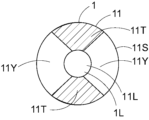
図4に示す通り、溝11Zは、周方向の一部において延在しており、周方向の全周にわたって延在していないことが好ましい。これにより軸方向1Xに力がかかったときに、第2部材12が溝11Z側に僅かに曲り易くなるため、チップ1の接触組織への突き刺さりを回避し易くすることができる。
As shown in FIG. 4, it is preferable that the groove 11Z extends in a part of the circumferential direction and does not extend all the way around the circumferential direction. This makes it easier for the second member 12 to bend slightly toward the groove 11Z when a force is applied in the axial direction 1X, making it easier to avoid the tip 1 sticking into the contact tissue.
図5に示す通り、非固定部11Yは、第1固定部11Tよりも内腔11L側に位置する部分と、第1固定部11Tよりも内腔11L側に位置していない部分とを有していてもよい。これにより、チップ1が多方向に曲り易くなるため、ガイドワイヤーへの追従性を向上することができる。なお第1対向面11Sは、周方向において複数の第1固定部11Tを有していてもよい。
As shown in FIG. 5, the non-fixed part 11Y has a part located closer to the inner cavity 11L than the first fixed part 11T, and a part not located closer to the inner cavity 11L than the first fixed part 11T. You can leave it there. This makes it easier for the tip 1 to bend in multiple directions, thereby improving the ability to follow the guide wire. Note that the first opposing surface 11S may have a plurality of first fixing portions 11T in the circumferential direction.
図5に示す通り、非固定部11Yは、チップ1の内腔1Lとチップ1外の空間とに連通していてもよい。患部によってはチップ1の一部が破断して残留しても健康上、問題の無い部分もあり、そのような患部にチップ1を挿入するに当たっては、チップ1の内腔1Lとチップ1外の空間とに連通する非固定部11Yを設けてチップ1の一部を破断し易くすることにより、チップ1の接触組織への突き刺さりをより一層、回避し易くすることができる。また、非固定部11Yがチップ1外の空間と連通していることにより、非固定部11Yを視認マーカーとして機能させることもできる。
As shown in FIG. 5, the non-fixed portion 11Y may communicate with the inner cavity 1L of the chip 1 and the space outside the chip 1. Depending on the affected area, there may be no health problems even if a part of the tip 1 breaks and remains, so when inserting the tip 1 into such an affected area, make sure that the inner cavity 1L of the tip 1 and the outside of the tip 1 are By providing the non-fixed portion 11Y that communicates with the space and making it easier to break a part of the tip 1, it is possible to further prevent the tip 1 from penetrating the contact tissue. Furthermore, since the non-fixed portion 11Y communicates with the space outside the chip 1, the non-fixed portion 11Y can also function as a visual marker.
図2に示す通り、第1対向面11Sは、第1固定部11Tよりも外側において、第2部材12に固定されていない非固定部を有していないことが好ましい。これにより、チップ1の挿入時においてチップ1の開口部分が外側に向かって広がる等の変形を防止し易くすることができる。
As shown in FIG. 2, the first opposing surface 11S preferably does not have a non-fixed part that is not fixed to the second member 12 on the outside of the first fixed part 11T. This makes it easier to prevent the opening portion of the chip 1 from being deformed, such as expanding outward, when the chip 1 is inserted.
図6、図7に示す通り、第1対向面11Sは、第2部材12に固定されている第2固定部11Uを有し、第2固定部11Uは、非固定部11Yよりも内腔11L側に位置していてもよい。これによりガイドワイヤーのチップ1の内腔1Lにおける引っかかりを回避し易くすることができる。
As shown in FIGS. 6 and 7, the first opposing surface 11S has a second fixed part 11U fixed to the second member 12, and the second fixed part 11U is larger than the non-fixed part 11Y in the inner cavity 11L. It may be located on the side. This makes it easier to avoid the guide wire from getting caught in the inner cavity 1L of the tip 1.
図6、図7に示す通り、非固定部11Yは第1固定部11Tよりも内腔11L側に位置し、且つ第2固定部11Uは、非固定部11Yよりも内腔11L側に位置していてもよい。このような配置によれば、非固定部11Yにより形成される間隙は径方向に封鎖されるため、チップ1の塑性変形を防止し易くすることができる。図示していないが、非固定部11Yは、周方向の一部において延在しており、周方向の全周にわたって延在していないことが好ましい。これにより軸方向1Xに力がかかったときに、第2部材12が非固定部11Y側に僅かに曲り易くなるため、チップ1の接触組織への突き刺さりを回避し易くすることができる。また図示していないが、図6、図7に示す第1対向面11Sは、更に、第2固定部11Uよりも内腔11L側に、非固定部を有していてもよい。当該非固定部は、内腔11Lの周方向に延在する溝であることが好ましい。更に当該非固定部は、周方向の一部において延在しており、周方向の全周にわたって延在していないことが好ましい。
As shown in FIGS. 6 and 7, the non-fixed part 11Y is located closer to the inner cavity 11L than the first fixed part 11T, and the second fixed part 11U is located closer to the inner cavity 11L than the non-fixed part 11Y. You can leave it there. According to such an arrangement, the gap formed by the non-fixed portion 11Y is closed in the radial direction, so that plastic deformation of the chip 1 can be easily prevented. Although not shown, it is preferable that the non-fixed portion 11Y extends in a part of the circumferential direction and does not extend all the way around the circumferential direction. This makes it easier for the second member 12 to bend slightly toward the non-fixed portion 11Y when a force is applied in the axial direction 1X, making it easier to avoid the tip 1 penetrating the contact tissue. Although not shown, the first opposing surface 11S shown in FIGS. 6 and 7 may further include a non-fixed portion closer to the inner cavity 11L than the second fixed portion 11U. It is preferable that the non-fixed portion is a groove extending in the circumferential direction of the inner cavity 11L. Further, it is preferable that the non-fixed portion extends in a part of the circumferential direction and does not extend all the way around the circumferential direction.
図6に示す通り、第2固定部11Uの外縁と軸方向1Xとのなす角度は、80度以上、100度以下であることが好ましく、85度以上、95度以下であることがより好ましく、88度以上、92度以下であることが更に好ましい。第2固定部11Uの外縁と軸方向1Xとのなす角度が90度に近い方が第1部材11により第2部材12を遠位側に押し込み易くすることができる。
As shown in FIG. 6, the angle between the outer edge of the second fixing part 11U and the axial direction 1X is preferably 80 degrees or more and 100 degrees or less, more preferably 85 degrees or more and 95 degrees or less, More preferably, the temperature is 88 degrees or more and 92 degrees or less. When the angle between the outer edge of the second fixing portion 11U and the axial direction 1X is closer to 90 degrees, it is easier to push the second member 12 distally by the first member 11.
図8に示す通り、第1対向面11Sは、周方向において、複数の第1固定部11Tと、それぞれ複数の第1固定部11Tの間に配置された複数の非固定部11Yとを有していてもよい。このように第1対向面11Sは、2つ以上の非固定部を有していてもよい。これにより、チップ1が多方向に曲り易くなるため、ガイドワイヤーへの追従性を向上することができる。
As shown in FIG. 8, the first opposing surface 11S includes, in the circumferential direction, a plurality of first fixed portions 11T and a plurality of non-fixed portions 11Y each disposed between the plurality of first fixed portions 11T. You can leave it there. In this way, the first opposing surface 11S may have two or more non-fixed parts. This makes it easier for the tip 1 to bend in multiple directions, thereby improving the ability to follow the guide wire.
図1に示す通り、第1部材11は、第1部材11の遠位端11Bに向かって外径が大きくなっている拡径部を有していることが好ましい。拡径部は、遠位端11Bに向かって外径が連続的に大きくなっていることが好ましい。これにより、第1部材11の遠位側が肉厚になるため第2部材12を遠位側に押し込み易くすることができる。側面視における拡径部の外縁は、直線状および/または曲線状であることが好ましく、直線状であることがより好ましい。なお第1部材11は、拡径部を2つ以上、有していてもよい。
As shown in FIG. 1, it is preferable that the first member 11 has an enlarged diameter portion whose outer diameter increases toward the distal end 11B of the first member 11. It is preferable that the outer diameter of the expanded diameter portion continuously increases toward the distal end 11B. As a result, the distal side of the first member 11 becomes thicker, making it easier to push the second member 12 toward the distal side. The outer edge of the enlarged diameter portion in side view is preferably linear and/or curved, more preferably linear. Note that the first member 11 may have two or more enlarged diameter portions.
図示していないが、第1部材11は、拡径部よりも遠位側に外径の大きさが一定である定径部を有していてもよい。これにより、第1部材11により第2部材12を遠位側に押し込み易くすることができる。
Although not shown, the first member 11 may have a constant diameter portion having a constant outer diameter on the distal side of the enlarged diameter portion. This allows the first member 11 to easily push the second member 12 toward the distal side.
第1部材11の軸方向の長さは、第1部材11の最大外径より長いことが好ましい。これにより、第1部材11を狭窄部に挿入し易くすることができる。
The length of the first member 11 in the axial direction is preferably longer than the maximum outer diameter of the first member 11. Thereby, the first member 11 can be easily inserted into the narrowed portion.
図1に示す通り、第2部材12は、第2部材12の遠位端12Bに向かって外径が小さくなっている縮径部を有していることが好ましい。縮径部は、遠位端12Bに向かって外径が連続的に小さくなっていることが好ましい。これにより、第2部材12の遠位側が先細り形状になるため第2部材12を狭窄部に押し込み易くすることができる。側面視における縮径部の外縁は、直線状および/または曲線状であることが好ましく、直線状であることがより好ましい。なお第2部材12は、縮径部を2つ以上、有していてもよい。
As shown in FIG. 1, the second member 12 preferably has a reduced diameter portion where the outer diameter decreases toward the distal end 12B of the second member 12. It is preferable that the outer diameter of the reduced diameter portion decreases continuously toward the distal end 12B. As a result, the distal side of the second member 12 has a tapered shape, so that the second member 12 can be easily pushed into the narrowed portion. The outer edge of the reduced diameter portion in side view is preferably linear and/or curved, more preferably linear. Note that the second member 12 may have two or more reduced diameter portions.
図1に示す通り、チップ1の側面視において、拡径部の外縁の軸方向1Xに対する傾斜角度は、縮径部の外縁の軸方向1Xに対する傾斜角度よりも大きいことが好ましい。これにより、第2部材12により第1部材11を遠位側に押し込み易くすることができると共に、第2部材12を狭窄部に挿入し易くすることができる。
As shown in FIG. 1, in a side view of the tip 1, the angle of inclination of the outer edge of the enlarged diameter portion with respect to the axial direction 1X is preferably larger than the angle of inclination of the outer edge of the reduced diameter portion with respect to the axial direction 1X. This makes it easier to push the first member 11 distally by the second member 12, and also makes it easier to insert the second member 12 into the stenosis.
第2部材12は、チップ1の遠位端1Bを含んでいることが好ましい。これにより第2部材12を狭窄部に押し込み易くすることができる。またチップ1は第2部材12よりも遠位側に他の部材を含んでいないことが好ましい。
Preferably, the second member 12 includes the distal end 1B of the tip 1. This makes it easier to push the second member 12 into the narrowed portion. Further, it is preferable that the tip 1 does not include any other member distal to the second member 12.
図示していないが、第2部材12は、縮径部よりも近位側に外径の大きさが一定である定径部を有していてもよい。これにより、第2部材12をより一層、遠位側に押し込み易くすることができる。
Although not shown, the second member 12 may have a constant diameter portion having a constant outer diameter on the proximal side of the reduced diameter portion. This makes it easier to push the second member 12 toward the distal side.
第2部材12の軸方向の長さは、第1部材11の軸方向の長さよりも長いことが好ましい。これにより、チップ1全体にかかる力が第1部材11と第2部材12の間の間隙により緩衝され易くなる。第1部材11の軸方向の長さとは、第1部材11の近位端11Aから遠位端11Bの軸方向の長さであり、第2部材12の軸方向の長さとは、第2部材12の近位端12Aから遠位端12Bの軸方向の長さである。
The length of the second member 12 in the axial direction is preferably longer than the length of the first member 11 in the axial direction. Thereby, the force applied to the entire chip 1 is easily damped by the gap between the first member 11 and the second member 12. The axial length of the first member 11 is the axial length from the proximal end 11A to the distal end 11B of the first member 11, and the axial length of the second member 12 is the axial length of the second member 11. It is the length in the axial direction from the proximal end 12A to the distal end 12B of No. 12.
第2部材12の軸方向の長さは、第2部材12の最大外径より長いことが好ましい。これにより、第2部材12を狭窄部に挿入し易くすることができる。
The length of the second member 12 in the axial direction is preferably longer than the maximum outer diameter of the second member 12. Thereby, the second member 12 can be easily inserted into the narrowed portion.
第1部材11は第1樹脂を含み、第2部材12は、第1樹脂の融点と同じか又は第1樹脂の融点よりも低い融点を有する第2樹脂を含むことが好ましい。これにより、後述するように内側チューブ2に固定した第1部材11に対して、第2部材12を加熱により固定する場合に、第2部材12の固定の際の加熱温度を低減することができるため、内側チューブ2にかかる熱ストレスを低減できる。第1部材11は第1樹脂からなることがより好ましい。第2部材12は、第1樹脂の融点と同じか又は第1樹脂の融点よりも低い融点を有する第2樹脂からなることがより好ましい。また第2部材12の融点は、第1部材11の融点と同じか又は第1部材11の融点よりも低いことが好ましく、第1部材11の融点よりも低いことがより好ましい。融点は、例えばDSCにより測定することができ、DSC曲線の吸熱ピークのトップを示す温度を融点とすることが好ましい。
It is preferable that the first member 11 contains a first resin, and the second member 12 contains a second resin having a melting point that is the same as or lower than the melting point of the first resin. Thereby, when fixing the second member 12 by heating to the first member 11 fixed to the inner tube 2 as described later, it is possible to reduce the heating temperature when fixing the second member 12. Therefore, thermal stress applied to the inner tube 2 can be reduced. More preferably, the first member 11 is made of a first resin. It is more preferable that the second member 12 is made of a second resin having a melting point that is the same as or lower than the melting point of the first resin. Further, the melting point of the second member 12 is preferably the same as or lower than the melting point of the first member 11, and more preferably lower than the melting point of the first member 11. The melting point can be measured, for example, by DSC, and it is preferable that the temperature at which the top of the endothermic peak of the DSC curve appears is determined as the melting point.
第1部材11は、例えば以下の方法により第2部材12に固定することが好ましい。具体的には図9に示す通り、第1部材11の内腔11Lに医療用装置の内側チューブ2の遠位端部2bを挿入して第1部材11を内側チューブ2に固定した後に、第1部材11の第1対向面11Sの少なくとも一部を第2部材12の第2対向面12Sに接触させてから、第1部材11を第2部材12に固定することが好ましい。これにより、第1部材11を第2部材12に固定してから第1部材11を内側チューブ2に固定する場合よりも、第1部材11と第2部材12の固定部に対する製造時の熱ストレス等を低減できるため、第1部材11の第2部材12の固定部の固定強度を維持し易くすることができる。
The first member 11 is preferably fixed to the second member 12, for example, by the following method. Specifically, as shown in FIG. 9, after inserting the distal end 2b of the inner tube 2 of the medical device into the inner cavity 11L of the first member 11 and fixing the first member 11 to the inner tube 2, the first member 11 is fixed to the inner tube 2. It is preferable to fix the first member 11 to the second member 12 after bringing at least a portion of the first opposing surface 11S of the first member 11 into contact with the second opposing surface 12S of the second member 12. This reduces the thermal stress during manufacturing on the fixed portion of the first member 11 and second member 12, compared to the case where the first member 11 is fixed to the second member 12 and then the first member 11 is fixed to the inner tube 2. etc., it is possible to easily maintain the fixing strength of the fixing portion of the second member 12 of the first member 11.
第1部材11と第2部材12とを固定する方法としては、溶着が好ましく、熱溶着がより好ましい。熱溶着としては熱風溶着が好ましい。例えば、図1~図3に示すチップ1は、第1部材11の第1対向面11Sを第2部材12の第2対向面12Sに接触させた状態で、内腔1Lに冷却した芯材を挿入して、次いで第1部材11と第2部材12の接触部を外部から熱風により溶着することにより形成することができる。また図4に示すチップ1は、例えば、一部のみを冷却した芯材を内腔1Lに挿入して、上記と同様に外部から熱風により溶着することにより形成することができる。また図5に示すチップ1は、例えば、内腔1Lに冷却した芯材を挿入して、第1部材11と第2部材12の接触部を径方向において部分的に熱風を当てることにより形成することができる。図6、図7に示すチップ1は、例えばチップ1の融点+10℃以内の温度にて芯材を加熱しつつ、同温度にて外部からの熱風による加熱を好ましくは1秒以上、5秒以下の間行うことにより形成することができる。図8に示すチップ1は、第1部材11と第2部材12の接触部を径方向において、外部から部分的に熱風を当てることにより形成することができる。
As a method for fixing the first member 11 and the second member 12, welding is preferable, and thermal welding is more preferable. As the thermal welding, hot air welding is preferred. For example, in the chip 1 shown in FIGS. 1 to 3, a cooled core material is inserted into the inner cavity 1L with the first opposing surface 11S of the first member 11 in contact with the second opposing surface 12S of the second member 12. After the first member 11 and the second member 12 are inserted, the contact portion between the first member 11 and the second member 12 can be formed by welding from the outside with hot air. Further, the chip 1 shown in FIG. 4 can be formed, for example, by inserting a partially cooled core material into the inner cavity 1L and welding it from the outside with hot air in the same manner as described above. Further, the chip 1 shown in FIG. 5 is formed by, for example, inserting a cooled core material into the inner cavity 1L and applying hot air partially to the contact portion between the first member 11 and the second member 12 in the radial direction. be able to. For the chip 1 shown in FIGS. 6 and 7, for example, the core material is heated to a temperature within the melting point of the chip 1 +10°C, and the heating is preferably performed by external hot air at the same temperature for 1 second or more and 5 seconds or less. It can be formed by performing the process for a while. The chip 1 shown in FIG. 8 can be formed by partially applying hot air to the contact portion between the first member 11 and the second member 12 in the radial direction from the outside.
第1部材11と第2部材12は、接着剤により固定してもよい。接着剤としては、例えば、ホットメルト型接着剤、湿気硬化型接着剤、紫外線硬化型接着剤、2液硬化型接着剤が挙げられる。これらのうちホットメルト型接着剤または湿気硬化型接着剤が好ましい。また接着剤としては、例えば、アクリル系接着剤、ポリウレタン系接着剤、シアノアクリレート系接着剤、シリコーン系接着剤、酢酸ビニル系接着剤、エポキシ系接着剤が挙げられる。これらは1種のみを用いてもよく、2種以上を併用してもよい。
The first member 11 and the second member 12 may be fixed with an adhesive. Examples of the adhesive include hot melt adhesives, moisture curing adhesives, ultraviolet curable adhesives, and two-component curing adhesives. Among these, hot-melt adhesives and moisture-curing adhesives are preferred. Examples of adhesives include acrylic adhesives, polyurethane adhesives, cyanoacrylate adhesives, silicone adhesives, vinyl acetate adhesives, and epoxy adhesives. These may be used alone or in combination of two or more.
第1部材11と第2部材12は、それぞれ、樹脂を含むことが好ましく、樹脂からなることがより好ましい。樹脂は熱可塑性樹脂であることが好ましい。樹脂として具体的には、ポリエチレン、ポリプロピレン等のポリオレフィン樹脂、ポリアミド、ポリエーテルポリアミド等のポリアミド樹脂、ポリエチレンテレフタレート、ポリブチレンテレフタレート等のポリエステル樹脂、ポリテトラフルオロエチレン、テトラフルオロエチレン・ヘキサフルオロプロピレン共重合体等のフッ素樹脂、ポリ塩化ビニル樹脂、シリコーン樹脂、ポリウレタン樹脂、エチレン-酢酸ビニル共重合樹脂、ポリエーテルエーテルケトン樹脂、ポリエーテルイミド樹脂、ポリオレフィンエラストマー、ポリアミドエラストマー、ポリエステルエラストマー、ポリウレタンエラストマー、またはこれらの混合物であることが好ましい。これらは1種のみを用いてもよく、2種以上を併用してもよい。また第1部材11と第2部材12は、それぞれ、加水分解防止剤、難燃剤、充填材、架橋剤等の添加剤を含んでいてもよい。第1部材11と第2部材12は、同じ樹脂を含んでいてもよいが、異なる樹脂を含むことが好ましい。また第1部材11と第2部材12は、それぞれ、多層構造を有していてもよく、各層は異なる樹脂を含んでいてもよく、同じ樹脂を含んでいてもよい。
The first member 11 and the second member 12 each preferably contain resin, and are more preferably made of resin. Preferably, the resin is a thermoplastic resin. Specifically, the resins include polyolefin resins such as polyethylene and polypropylene, polyamide resins such as polyamide and polyether polyamide, polyester resins such as polyethylene terephthalate and polybutylene terephthalate, polytetrafluoroethylene, and tetrafluoroethylene/hexafluoropropylene copolymers. Fluororesins such as combinations, polyvinyl chloride resins, silicone resins, polyurethane resins, ethylene-vinyl acetate copolymer resins, polyetheretherketone resins, polyetherimide resins, polyolefin elastomers, polyamide elastomers, polyester elastomers, polyurethane elastomers, or these Preferably, it is a mixture of. These may be used alone or in combination of two or more. Further, the first member 11 and the second member 12 may each contain additives such as a hydrolysis inhibitor, a flame retardant, a filler, and a crosslinking agent. The first member 11 and the second member 12 may contain the same resin, but preferably contain different resins. Further, the first member 11 and the second member 12 may each have a multilayer structure, and each layer may contain a different resin or the same resin.
第1部材11、第2部材12は、それぞれ上記樹脂を用いて、例えば射出成形や押出成形することにより製造することができる。
The first member 11 and the second member 12 can be manufactured using the above resins, for example, by injection molding or extrusion molding.
チップ1は、上記樹脂を含むことが好ましく、上記樹脂からなることが好ましい。チップ1は、上記樹脂と混錬されたX線不透過性粒子および/またはX線不透過性のマーカーバンドを有していてもよい。X線不透過性粒子としては、例えばX線不透過性物質からなる粒子が挙げられる。X線不透過性のマーカーバンドとしては、例えばX線不透過性物質からなるマーカーバンドが挙げられる。X線不透過性物質は、金、白金、銀、タングステン、タンタル、イリジウム、パラジウム、レニウム、ロジウム、スズ、ニッケル、チタン、これらの合金、硫酸バリウム、ビスマス化合物、タングステン化合物、またはこれらの混合物であることが好ましい。合金は、金-パラジウム合金、白金-イリジウム合金、NiTiPd合金、NiTiAu合金、NiTi合金またはこれらの混合物であることが好ましい。これらは1種のみを用いてもよく、2種以上を併用してもよい。
The chip 1 preferably contains the above resin, and is preferably made of the above resin. The chip 1 may have X-ray opaque particles and/or X-ray opaque marker bands kneaded with the resin. Examples of the X-ray opaque particles include particles made of an X-ray opaque substance. Examples of the radiopaque marker band include marker bands made of a radiopaque substance. The radiopaque material can be gold, platinum, silver, tungsten, tantalum, iridium, palladium, rhenium, rhodium, tin, nickel, titanium, alloys thereof, barium sulfate, bismuth compounds, tungsten compounds, or mixtures thereof. It is preferable that there be. Preferably, the alloy is a gold-palladium alloy, a platinum-iridium alloy, a NiTiPd alloy, a NiTiAu alloy, a NiTi alloy or a mixture thereof. These may be used alone or in combination of two or more.
以上、実施の形態に係るチップについて説明したが、以下では、実施の形態にかかる医療用装置について説明する。図10、図11に示す通り、実施の形態に係る医療用装置10は、医療用具4を体内に搬送する医療用装置であって、内側チューブ2と、内腔3Lに内側チューブ2の少なくとも一部が配置されている外側チューブ3と、内側チューブ2の遠位端部2bの少なくとも一部に固定されているチップ1と、内側チューブ2の遠位端部2bの外側面2Oと、外側チューブ3の内側面3Iとの間に配置されている医療用具4とを有している。
Although the chip according to the embodiment has been described above, the medical device according to the embodiment will be described below. As shown in FIGS. 10 and 11, the medical device 10 according to the embodiment is a medical device for transporting a medical device 4 into the body, and includes an inner tube 2 and at least one portion of the inner tube 2 in the inner cavity 3L. an outer tube 3 in which a part is arranged; a tip 1 fixed to at least a part of the distal end 2b of the inner tube 2; an outer surface 2O of the distal end 2b of the inner tube 2; 3 and an inner surface 3I of the medical device 4.
内側チューブ2は内腔2Lを有し、内腔2Lはガイドワイヤーを挿入できるように構成されている。これにより、ガイドワイヤーに沿って内側チューブ2等を移動させて医療用具4等を狭窄部まで送達することができる。
The inner tube 2 has a lumen 2L, and the lumen 2L is configured so that a guide wire can be inserted therein. Thereby, the medical device 4 and the like can be delivered to the stenosis by moving the inner tube 2 and the like along the guide wire.
内側チューブ2の遠位端部2bの少なくとも一部は、チップ1の内側面に固定されていることが好ましい。そのため、チップ1の内腔1Lの一部は、内側チューブ2の遠位端部2bを収容できるように、内側チューブ2の外径以上の径を有していることが好ましい。更に、チップ1の内腔1Lの他の部分は、内側チューブ2の内腔2Lの径以下の径を有していてもよい。チップ1と内側チューブ2は熱溶着等により直接固定されていてもよく、接着剤等を用いて間接的に固定されていてもよい。
Preferably, at least a portion of the distal end 2b of the inner tube 2 is fixed to the inner surface of the tip 1. Therefore, it is preferable that a part of the inner cavity 1L of the tip 1 has a diameter equal to or larger than the outer diameter of the inner tube 2 so that the distal end 2b of the inner tube 2 can be accommodated therein. Furthermore, the other portion of the lumen 1L of the tip 1 may have a diameter equal to or less than the diameter of the lumen 2L of the inner tube 2. The chip 1 and the inner tube 2 may be directly fixed by thermal welding or the like, or may be indirectly fixed using an adhesive or the like.
内側チューブ2の遠位端は、チップ1の第1部材11の遠位端11Bよりも近位側にあることが好ましい。これにより、第2部材12にかかる力を、第1部材11と第2部材12の間の間隙により、緩衝し易くすることができる。
The distal end of the inner tube 2 is preferably located closer to the proximal side than the distal end 11B of the first member 11 of the tip 1. Thereby, the force applied to the second member 12 can be easily damped by the gap between the first member 11 and the second member 12.
第1部材11は、内側チューブ2に固定されており、第2部材12は、内側チューブ2に固定されていないことが好ましい。これにより、第2部材12にかかる力を、第1部材11と第2部材12の間の間隙により緩衝し易くすることができる。
It is preferable that the first member 11 is fixed to the inner tube 2 and the second member 12 is not fixed to the inner tube 2. Thereby, the force applied to the second member 12 can be easily buffered by the gap between the first member 11 and the second member 12.
内側チューブ2は、少なくとも一部が外側チューブ3の内腔3Lに配置されていればよい。内側チューブ2の遠位端は、外側チューブ3の遠位端よりも遠位側に位置することが好ましい。これによりキンクを防いだり、剛性段差を低減することができる。また、内側チューブ2の近位部は外側チューブ3の近位部に直接または間接に、着脱可能に固定されていることが好ましい。これにより、デリバリー時には上記固定を行って意図しない医療用具4の動作を防止する一方で、医療用具4を動作させるときには、上記固定を外して外側チューブ3を近位側に移動させることにより医療用具4を動作させることができる。医療用具4の動作には、拡張、展開、脱離等の動作が含まれる。なお上記着脱は、後述する外側ハンドル部材7を介して行うことができる。
It is sufficient that at least a portion of the inner tube 2 is disposed in the inner cavity 3L of the outer tube 3. Preferably, the distal end of the inner tube 2 is located more distally than the distal end of the outer tube 3. This can prevent kinks and reduce rigidity differences. Further, it is preferable that the proximal portion of the inner tube 2 is detachably fixed directly or indirectly to the proximal portion of the outer tube 3. As a result, during delivery, the above-mentioned fixation is performed to prevent unintended movement of the medical device 4, while when the medical device 4 is to be operated, the above-mentioned fixation is removed and the outer tube 3 is moved proximally, thereby preventing the medical device 4 from moving unintentionally. 4 can be operated. The operations of the medical device 4 include operations such as expansion, deployment, and detachment. Note that the above-mentioned attachment and detachment can be performed via an outer handle member 7, which will be described later.
医療用具4は、後述する自己拡張型である場合、内側チューブ2の遠位端部2bの外側面2Oと、外側チューブ3の内側面3Iとの間に配置されていることにより、収縮状態を維持することができ、外側チューブ3よりも遠位側に移動することにより拡張することができる。またチップ1により、医療用具4を狭窄部に配置する前に外側チューブ3よりも遠位側に医療用具4が移動して展開してしまう等の誤作動を回避することができる。
When the medical device 4 is a self-expanding type described below, it is placed between the outer surface 2O of the distal end 2b of the inner tube 2 and the inner surface 3I of the outer tube 3, so that the medical device 4 can maintain a contracted state. It can be maintained and expanded by moving distally from the outer tube 3. Furthermore, the tip 1 can avoid malfunctions such as the medical device 4 moving distally from the outer tube 3 and being deployed before the medical device 4 is placed in the stenotic region.
医療用具4の遠位端4Bは、第1対向面11Sの非固定部11Yよりも近位側に位置することが好ましい。これにより、デリバリー時のチップ1の動きに伴う医療用具4の遠位端4Bの損傷を回避し易くすることができる。一方、医療用具4の遠位端4Bは、第1部材11の近位端11Aよりも遠位側に位置することが好ましい。これにより医療用具4の軸方向の動きを低減して、位置ズレを防止することができる。また、医療用具4の遠位端部とチップ1が重なることで、剛性段差を減らしたり、キンクを防止し易くすることができる。
It is preferable that the distal end 4B of the medical device 4 is located closer to the proximal side than the non-fixed portion 11Y of the first opposing surface 11S. Thereby, damage to the distal end 4B of the medical device 4 due to movement of the tip 1 during delivery can be easily avoided. On the other hand, it is preferable that the distal end 4B of the medical device 4 is located more distally than the proximal end 11A of the first member 11. Thereby, the movement of the medical device 4 in the axial direction can be reduced and positional deviation can be prevented. Furthermore, by overlapping the distal end of the medical device 4 and the tip 1, it is possible to reduce the difference in rigidity and make it easier to prevent kinks.
図11に示す通り、内側チューブ2は、近位端部2aに内側ハンドル部材6を有することが好ましい。また外側チューブ3は、近位端部3aに外側ハンドル部材7を有することが好ましい。これにより、例えば内側ハンドル部材6を把持したままの状態で、外側ハンドル部材7を介して外側チューブ3を引くことにより、医療用具4が外側チューブ3よりも遠位側に位置する状態になって動作することができる。
As shown in FIG. 11, the inner tube 2 preferably has an inner handle member 6 at the proximal end 2a. The outer tube 3 also preferably has an outer handle member 7 at the proximal end 3a. As a result, for example, by pulling the outer tube 3 through the outer handle member 7 while holding the inner handle member 6, the medical device 4 can be positioned on the distal side of the outer tube 3. can work.
内側チューブ2の外側面2Oには、プッシャー部材5が固定されていることが好ましい。プッシャー部材5により、医療用具4を押し出し易くすることができる。プッシャー部材5は管状体であることが好ましい。
It is preferable that the pusher member 5 is fixed to the outer surface 2O of the inner tube 2. The pusher member 5 allows the medical device 4 to be pushed out easily. It is preferable that the pusher member 5 is a tubular body.
図12に示す通り、外側チューブ3は、軸方向に移動可能であってもよい。例えば、医療用装置10は、内腔3XLに外側チューブ3の少なくとも一部が配置されている最外側チューブ3Xと、外側チューブ3の近位端部3aに遠位端部3Ybが固定された線状部材3Yとを有していることが好ましい。更に、最外側チューブ3Xと内側チューブ2は、近位端部3Xaと近位端部2aに内側ハンドル部材6を有していることがより好ましい。このような態様により、例えば内側ハンドル部材6を把持したまま、外側ハンドル部材7を介して線状部材3Yを手元側に引くことにより、最外側チューブ3X内で外側チューブ3を手元側に引き戻すことができ、医療用具4を動作させることができる。なお線状部材3Yは、サムホイール等の回転体、及び回転体に巻き取られるものであってもよい。
As shown in FIG. 12, the outer tube 3 may be movable in the axial direction. For example, the medical device 10 includes an outermost tube 3X in which at least a portion of the outer tube 3 is disposed in the inner lumen 3XL, and a line in which the distal end 3Yb is fixed to the proximal end 3a of the outer tube 3. It is preferable to have a shaped member 3Y. Furthermore, it is more preferable that the outermost tube 3X and the inner tube 2 have inner handle members 6 at the proximal end 3Xa and the proximal end 2a. With this configuration, for example, by pulling the linear member 3Y toward the user's hand via the outer handle member 7 while holding the inner handle member 6, the outer tube 3 can be pulled back toward the user's hand within the outermost tube 3X. , and the medical device 4 can be operated. Note that the linear member 3Y may be a rotating body such as a thumbwheel, or may be wound around a rotating body.
図11に示す通り、外側ハンドル部材7は、フラッシュ用内腔8を有していてもよい。これにより、フラッシュ用内腔8から所望の液体を外側チューブ3の内腔3L内に注入することができる。
As shown in FIG. 11, the outer handle member 7 may have a flush lumen 8. Thereby, a desired liquid can be injected from the flushing lumen 8 into the lumen 3L of the outer tube 3.
外側チューブ3は遠位端部3bにX線不透過性を有するX線不透過性領域を有していてもよい。これにより、外側チューブ3の遠位端部3bの位置を把握することができる。X線不透過性領域は、チップ1の第1部材11の遠位端11Bよりも近位側であって、近位端11Aよりも遠位側に位置することが好ましい。これにより、外側チューブ3は遠位端部3bの剛性を高めることができる。X線不透過性領域は、樹脂と混錬されたX線不透過性粒子および/またはX線不透過性のマーカーバンドを含有していてもよい。X線不透過性粒子としては、例えばX線不透過性物質からなる粒子が挙げられる。X線不透過性のマーカーバンドとしては、例えばX線不透過性物質からなるマーカーバンドが挙げられる。X線不透過性物質については、チップ1のX線不透過性物質の説明の記載を参照すればよい。
The outer tube 3 may have an X-ray opaque region at the distal end 3b. Thereby, the position of the distal end portion 3b of the outer tube 3 can be grasped. The radiopaque region is preferably located more proximally than the distal end 11B of the first member 11 of the chip 1 and more distally than the proximal end 11A. Thereby, the outer tube 3 can increase the rigidity of the distal end portion 3b. The radiopaque region may contain radiopaque particles and/or radiopaque marker bands intermixed with the resin. Examples of the X-ray opaque particles include particles made of an X-ray opaque substance. Examples of the radiopaque marker band include marker bands made of a radiopaque substance. Regarding the X-ray opaque substance, refer to the description of the X-ray opaque substance in the chip 1.
内側チューブ2、外側チューブ3、プッシャー部材5、最外側チューブ3Xは、それぞれ、樹脂を含むことが好ましい。樹脂は、ポリエチレン、ポリイミド、ポリエーテルブロックアミド、ポリアミド、ポリウレタン、ポリエステル、シリコーン、ポリアミドエラストマー、PTFE、PFA等のフッ素樹脂、またはこれらの混合物を含むことが好ましい。これらは1種のみを用いてもよく、2種以上を併用してもよい。また樹脂は、加水分解防止剤、難燃剤、充填材、架橋剤等の添加剤を含んでいてもよい。内側チューブ2、外側チューブ3、最外側チューブ3Xは、それぞれ、内層及び外層を有していてもよい。内側チューブ2、外側チューブ3、最外側チューブ3Xは、管状の補強部材を有していてもよい。補強部材として、例えば、らせん状の線材、編組された線材等が挙げられる。線材は、例えば、ステンレス、チタン、コバルトクロム合金、Ni-Ti、タングステン、ポリアリレート繊維、アラミド繊維、超高分子量ポリエチレン繊維、PBO繊維、炭素繊維、これらの混合物が挙げられる。また線状部材3Yの素材としては、例えば、ステンレス、チタン、コバルトクロム合金、Ni-Ti、タングステン等が挙げられる。これらは1種のみを用いてもよく、2種以上を併用してもよい。
It is preferable that the inner tube 2, outer tube 3, pusher member 5, and outermost tube 3X each contain resin. Preferably, the resin includes polyethylene, polyimide, polyether block amide, polyamide, polyurethane, polyester, silicone, polyamide elastomer, fluororesin such as PTFE, PFA, or a mixture thereof. These may be used alone or in combination of two or more. The resin may also contain additives such as hydrolysis inhibitors, flame retardants, fillers, and crosslinking agents. The inner tube 2, the outer tube 3, and the outermost tube 3X may each have an inner layer and an outer layer. The inner tube 2, the outer tube 3, and the outermost tube 3X may have a tubular reinforcing member. Examples of the reinforcing member include a spiral wire rod, a braided wire rod, and the like. Examples of the wire include stainless steel, titanium, cobalt chromium alloy, Ni-Ti, tungsten, polyarylate fiber, aramid fiber, ultra-high molecular weight polyethylene fiber, PBO fiber, carbon fiber, and mixtures thereof. Furthermore, examples of the material of the linear member 3Y include stainless steel, titanium, cobalt chromium alloy, Ni--Ti, and tungsten. These may be used alone or in combination of two or more.
医療用具4は、X線不透過性物質を含むことが好ましい。これにより、医療用具4の位置をX線透視下で確認することができる。X線不透過性物質については、チップ1のX線不透過性物質の説明の記載を参照すればよい。医療用具4は、樹脂および/または金属を含んでいることが好ましく、金属を含んでいることがより好ましく、金属からなることが更に好ましい。
Preferably, the medical device 4 includes an X-ray opaque substance. Thereby, the position of the medical device 4 can be confirmed under X-ray fluoroscopy. Regarding the X-ray opaque substance, refer to the description of the X-ray opaque substance in the chip 1. The medical device 4 preferably contains resin and/or metal, more preferably contains metal, and still more preferably consists of metal.
医療用具4は、医療用管状体であることが好ましい。医療用管状体は、ステント、ステントグラフト、閉塞具、注入カテーテル、またはプロテーゼ弁であることが好ましく、ステントであることがより好ましい。ステントとしては、例えば、樹脂および/または金属の線状体で形成されたコイル状のステント、チューブをレーザーによって切り抜いて加工したステント、シートをレーザーで切り抜いた後に円筒形状に巻いてレーザー溶接したステント、線状体をレーザーによって溶接して組み立てたステント、複数の線状樹脂および/または金属を織って作成したステントが挙げられる。ステントは、ステントをマウントしたバルーンによって拡張させるバルーン拡張型ステント、またはステントの拡張を抑制する外部部材を取り除くことによって自ら拡張させる自己拡張型ステントであることが好ましく、自己拡張型ステントであることがより好ましい。また医療用具4は、管状以外の形状のステント、管状以外の形状のステントグラフト、管状以外の形状の閉塞具等であってもよい。管状以外の形状として例えば球状が挙げられる。また医療用具4は、内側チューブ2、外側チューブ3、及びチップ1と併用できるものであればよく、例えばバルーン、バスケット、スネア、または閉塞具等であってもよい。
Preferably, the medical device 4 is a medical tubular body. Preferably, the medical tubular body is a stent, stent graft, obturator, infusion catheter, or prosthetic valve, more preferably a stent. Stents include, for example, coiled stents made of linear resin and/or metal, stents made by cutting out a tube with a laser, and stents made by cutting out a sheet with a laser and then winding it into a cylindrical shape and laser welding it. , a stent made by welding linear bodies together using a laser, and a stent made by weaving a plurality of linear resins and/or metals. The stent is preferably a balloon-expandable stent that expands using a balloon mounted on the stent, or a self-expanding stent that expands by itself by removing an external member that inhibits the expansion of the stent. More preferred. Further, the medical device 4 may be a stent having a shape other than a tubular shape, a stent graft having a shape other than a tubular shape, an obturator having a shape other than a tubular shape, or the like. Examples of shapes other than tubular include spherical. Further, the medical device 4 may be any device as long as it can be used in conjunction with the inner tube 2, outer tube 3, and tip 1, and may be, for example, a balloon, a basket, a snare, or an obturator.
医療用装置10は、医療用管状体4を体内に搬送する医療用管状体搬送装置であることが好ましい。医療用装置10は、心臓の冠動脈、その他の血管、気管、食道、胆管、尿道等に生じた狭窄部に対して用いることができる。
The medical device 10 is preferably a medical tubular body transport device that transports the medical tubular body 4 into the body. The medical device 10 can be used for strictures occurring in the coronary arteries of the heart, other blood vessels, the trachea, the esophagus, the bile ducts, the urethra, and the like.
本願は、2022年3月17日に出願された日本国特許出願第2022-042700号に基づく優先権の利益を主張するものである。2022年3月17日に出願された日本国特許出願第2022-042700号の明細書の全内容が、本願に参考のため援用される。
This application claims the benefit of priority based on Japanese Patent Application No. 2022-042700 filed on March 17, 2022. The entire contents of the specification of Japanese Patent Application No. 2022-042700 filed on March 17, 2022 are incorporated by reference into this application.
1 チップ
1A チップの近位端
1B チップの遠位端
1L チップの内腔
1X チップの軸方向
2 内側チューブ
2a 内側チューブの近位端部
2b 内側チューブの遠位端部
2O 内側チューブの外側面
2L 内側チューブの内腔
3 外側チューブ
3a 外側チューブの近位端部
3b 外側チューブの遠位端部
3L 外側チューブの内腔
3I 外側チューブの内側面
3X 最外側チューブ
3Xa 近位端部
3XL 内腔
3Y 線状部材
3Yb 遠位端部
4 医療用具
4B 医療用具の遠位端
5 プッシャー部材
6 内側ハンドル部材
7 外側ハンドル部材
8 フラッシュ用内腔
10 医療用装置
10b 遠位端部
11 第1部材
11A 近位端
11B 遠位端
11b 遠位端部
11L 第1部材の内腔
11S 第1対向面
11T 第1固定部
11U 第2固定部
11Y 非固定部
11Z 溝
12 第2部材
12A 近位端
12B 遠位端
12L 内腔
12S 第2対向面 1Tip 1A Proximal end of the tip 1B Distal end of the tip 1L Internal lumen of the tip 1X Axial direction of the tip 2 Inner tube 2a Proximal end of the inner tube 2b Distal end of the inner tube 2O Outer surface of the inner tube 2L Inner lumen of inner tube 3 Outer tube 3a Proximal end of outer tube 3b Distal end of outer tube 3L Inner lumen of outer tube 3I Inner surface of outer tube 3X Outermost tube 3Xa Proximal end 3XL Inner lumen 3Y Line shaped member 3Yb distal end 4 medical device 4B distal end of medical device 5 pusher member 6 inner handle member 7 outer handle member 8 flush lumen 10 medical device 10b distal end 11 first member 11A proximal end 11B Distal end 11b Distal end 11L Lumen of first member 11S First opposing surface 11T First fixed part 11U Second fixed part 11Y Non-fixed part 11Z Groove 12 Second member 12A Proximal end 12B Distal end 12L Lumen 12S second opposing surface
1A チップの近位端
1B チップの遠位端
1L チップの内腔
1X チップの軸方向
2 内側チューブ
2a 内側チューブの近位端部
2b 内側チューブの遠位端部
2O 内側チューブの外側面
2L 内側チューブの内腔
3 外側チューブ
3a 外側チューブの近位端部
3b 外側チューブの遠位端部
3L 外側チューブの内腔
3I 外側チューブの内側面
3X 最外側チューブ
3Xa 近位端部
3XL 内腔
3Y 線状部材
3Yb 遠位端部
4 医療用具
4B 医療用具の遠位端
5 プッシャー部材
6 内側ハンドル部材
7 外側ハンドル部材
8 フラッシュ用内腔
10 医療用装置
10b 遠位端部
11 第1部材
11A 近位端
11B 遠位端
11b 遠位端部
11L 第1部材の内腔
11S 第1対向面
11T 第1固定部
11U 第2固定部
11Y 非固定部
11Z 溝
12 第2部材
12A 近位端
12B 遠位端
12L 内腔
12S 第2対向面 1
Claims (16)
- 体内に挿入される医療用装置の遠位端部に用いられるチップであって、
前記チップの近位端を含む第1部材と、
前記第1部材の遠位端部よりも遠位側に位置する第2部材とを有し、
前記第1部材は、前記第2部材に対向する第1対向面を有し、前記第1対向面は、前記第2部材に固定されている第1固定部と、前記第2部材に固定されていない非固定部とを有しているチップ。 A chip used at the distal end of a medical device inserted into the body,
a first member including a proximal end of the tip;
a second member located on the distal side of the distal end of the first member;
The first member has a first opposing surface facing the second member, and the first opposing surface includes a first fixing part fixed to the second member and a first fixing part fixed to the second member. A chip that does not have a non-fixed part. - 前記第1部材は、近位端から遠位端へ延在する内腔を有し、
前記第2部材は、近位端から遠位端へ延在し前記内腔に連通する内腔を有している請求項1に記載のチップ。 the first member has a lumen extending from a proximal end to a distal end;
The tip of claim 1, wherein the second member has a lumen extending from a proximal end to a distal end and communicating with the lumen. - 前記非固定部は、前記第1固定部よりも前記内腔側に位置している請求項2に記載のチップ。 The chip according to claim 2, wherein the non-fixed part is located closer to the lumen than the first fixed part.
- 前記第1対向面は、前記第2部材に固定されている第2固定部を有し、
前記第2固定部は、前記非固定部よりも前記内腔側に位置している請求項2に記載のチップ。 The first opposing surface has a second fixing part fixed to the second member,
The chip according to claim 2, wherein the second fixed part is located closer to the inner cavity than the non-fixed part. - 前記第1対向面は、前記非固定部よりも前記内腔側において、前記第2部材に固定されている固定部を有していない請求項2に記載のチップ。 The chip according to claim 2, wherein the first opposing surface does not have a fixing part fixed to the second member on the lumen side of the non-fixing part.
- 前記非固定部は、前記内腔の周方向に延在する溝である請求項2に記載のチップ。 The chip according to claim 2, wherein the non-fixed portion is a groove extending in the circumferential direction of the inner cavity.
- 前記溝は、前記周方向の一部において延在しており、前記周方向の全周にわたって延在していない請求項6に記載のチップ。 The chip according to claim 6, wherein the groove extends in a part of the circumferential direction and does not extend all the way around the circumferential direction.
- 前記第1対向面は、前記第1固定部よりも外側において、前記第2部材に固定されていない非固定部を有していない請求項1に記載のチップ。 The chip according to claim 1, wherein the first opposing surface does not have a non-fixed part that is not fixed to the second member on the outside of the first fixed part.
- 前記第1部材は、前記第1部材の前記遠位端に向かって外径が大きくなっている拡径部を有している請求項1に記載のチップ。 The tip according to claim 1, wherein the first member has an enlarged diameter portion whose outer diameter increases toward the distal end of the first member.
- 前記第1部材は第1樹脂を含み、
前記第2部材は、前記第1樹脂の融点と同じか又は前記第1樹脂の融点よりも低い融点を有する第2樹脂を含む請求項1に記載のチップ。 The first member includes a first resin,
The chip according to claim 1, wherein the second member includes a second resin having a melting point that is the same as or lower than the melting point of the first resin. - 前記第1対向面は、前記第1固定部において、溶着により前記第2部材に固定されている請求項1に記載のチップ。 The chip according to claim 1, wherein the first opposing surface is fixed to the second member by welding at the first fixing part.
- 前記医療用装置は、医療用管状体を体内に搬送する医療用管状体搬送装置である請求項1に記載のチップ。 The chip according to claim 1, wherein the medical device is a medical tubular body transport device that transports a medical tubular body into the body.
- 体内に挿入される医療用装置であって、
内側チューブと、
内腔に前記内側チューブの少なくとも一部が配置されている外側チューブと、
前記内側チューブの遠位端部の少なくとも一部に固定されている請求項1~12のいずれかに記載のチップと、
前記内側チューブの前記遠位端部の外側面と、前記外側チューブの内側面との間に配置されている医療用具とを有している医療用装置。 A medical device inserted into the body,
an inner tube;
an outer tube having at least a portion of the inner tube disposed in a lumen;
The chip according to any one of claims 1 to 12, which is fixed to at least a portion of the distal end of the inner tube;
A medical device having a medical device disposed between an outer surface of the distal end of the inner tube and an inner surface of the outer tube. - 前記医療用具の遠位端は、前記第1対向面の前記非固定部よりも近位側に位置する請求項13に記載の医療用装置。 The medical device according to claim 13, wherein the distal end of the medical device is located closer to the non-fixed portion of the first opposing surface.
- 前記第1部材は、前記内側チューブに固定されており、前記第2部材は、前記内側チューブに固定されていない請求項13に記載の医療用装置。 The medical device according to claim 13, wherein the first member is fixed to the inner tube, and the second member is not fixed to the inner tube.
- 前記医療用具は、医療用管状体であり、前記医療用管状体を体内に搬送する医療用管状体搬送装置である請求項13に記載の医療用装置。 The medical device according to claim 13, wherein the medical tool is a medical tubular body, and is a medical tubular body transport device that transports the medical tubular body into the body.
Applications Claiming Priority (2)
| Application Number | Priority Date | Filing Date | Title |
|---|---|---|---|
| JP2022042700 | 2022-03-17 | ||
| JP2022-042700 | 2022-03-17 |
Publications (1)
| Publication Number | Publication Date |
|---|---|
| WO2023176864A1 true WO2023176864A1 (en) | 2023-09-21 |
Family
ID=88023871
Family Applications (1)
| Application Number | Title | Priority Date | Filing Date |
|---|---|---|---|
| PCT/JP2023/009980 WO2023176864A1 (en) | 2022-03-17 | 2023-03-15 | Chip used at distal end of medical device to be inserted into body, and medical device |
Country Status (1)
| Country | Link |
|---|---|
| WO (1) | WO2023176864A1 (en) |
Citations (4)
| Publication number | Priority date | Publication date | Assignee | Title |
|---|---|---|---|---|
| WO2014115273A1 (en) * | 2013-01-23 | 2014-07-31 | テルモ株式会社 | Self-expanding stent system |
| WO2018051926A1 (en) * | 2016-09-14 | 2018-03-22 | テルモ株式会社 | Catheter |
| JP2019535388A (en) * | 2016-11-16 | 2019-12-12 | テウン メディカル カンパニー リミテッド | Stent delivery system with monopolar electrocautery tip |
| JP2020062321A (en) * | 2018-10-19 | 2020-04-23 | 朝日インテック株式会社 | catheter |
-
2023
- 2023-03-15 WO PCT/JP2023/009980 patent/WO2023176864A1/en unknown
Patent Citations (4)
| Publication number | Priority date | Publication date | Assignee | Title |
|---|---|---|---|---|
| WO2014115273A1 (en) * | 2013-01-23 | 2014-07-31 | テルモ株式会社 | Self-expanding stent system |
| WO2018051926A1 (en) * | 2016-09-14 | 2018-03-22 | テルモ株式会社 | Catheter |
| JP2019535388A (en) * | 2016-11-16 | 2019-12-12 | テウン メディカル カンパニー リミテッド | Stent delivery system with monopolar electrocautery tip |
| JP2020062321A (en) * | 2018-10-19 | 2020-04-23 | 朝日インテック株式会社 | catheter |
Similar Documents
| Publication | Publication Date | Title |
|---|---|---|
| US10517720B2 (en) | Expandable sheath for introducing an endovascular delivery device into a body | |
| JP2006513774A (en) | Multi-braided outer tube | |
| JP2022504291A (en) | Medical implant delivery system | |
| US20060229589A1 (en) | Catheter | |
| JP2010527258A (en) | Hypotube catheter | |
| WO2020162287A1 (en) | Extension catheter and method for producing same | |
| CN113646030B (en) | balloon catheter | |
| AU2007286886B2 (en) | Loop tip wire guide | |
| JPWO2018181326A1 (en) | Stent delivery device | |
| WO2018092387A1 (en) | Catheter assembly | |
| WO2020153321A1 (en) | Support catheter | |
| WO2023176864A1 (en) | Chip used at distal end of medical device to be inserted into body, and medical device | |
| US20220000647A1 (en) | Stent delivery apparatus | |
| JP2016116815A (en) | Indwelling implement delivery device | |
| JP7444879B2 (en) | Catheter and catheter manufacturing method | |
| JP2020039376A (en) | Balloon catheter | |
| CN113645926A (en) | Medical tubular body transport device and method for manufacturing same | |
| JP7555506B1 (en) | Medical device auxiliary tools, guide wire assemblies and medical device assemblies | |
| JP7498709B2 (en) | catheter | |
| JP7524080B2 (en) | Extension catheter and method for manufacturing same | |
| JPWO2018181315A1 (en) | Balloon catheter and method for manufacturing medical long body | |
| EP4183438A1 (en) | Catheter | |
| WO2023119399A1 (en) | Medical instrument | |
| WO2024166551A1 (en) | Medical device and production method for medical device | |
| WO2023153470A1 (en) | Chip used at distal end of medical device inserted into body, and medical tube conveyance device |
Legal Events
| Date | Code | Title | Description |
|---|---|---|---|
| 121 | Ep: the epo has been informed by wipo that ep was designated in this application |
Ref document number: 23770817 Country of ref document: EP Kind code of ref document: A1 |
|
| ENP | Entry into the national phase |
Ref document number: 2024508206 Country of ref document: JP Kind code of ref document: A |