WO2023176769A1 - 液面検出装置 - Google Patents
液面検出装置 Download PDFInfo
- Publication number
- WO2023176769A1 WO2023176769A1 PCT/JP2023/009593 JP2023009593W WO2023176769A1 WO 2023176769 A1 WO2023176769 A1 WO 2023176769A1 JP 2023009593 W JP2023009593 W JP 2023009593W WO 2023176769 A1 WO2023176769 A1 WO 2023176769A1
- Authority
- WO
- WIPO (PCT)
- Prior art keywords
- regulating
- arm
- liquid level
- overlapping
- float
- Prior art date
- Legal status (The legal status is an assumption and is not a legal conclusion. Google has not performed a legal analysis and makes no representation as to the accuracy of the status listed.)
- Ceased
Links
Images






Classifications
-
- G—PHYSICS
- G01—MEASURING; TESTING
- G01F—MEASURING VOLUME, VOLUME FLOW, MASS FLOW OR LIQUID LEVEL; METERING BY VOLUME
- G01F23/00—Indicating or measuring liquid level or level of fluent solid material, e.g. indicating in terms of volume or indicating by means of an alarm
- G01F23/30—Indicating or measuring liquid level or level of fluent solid material, e.g. indicating in terms of volume or indicating by means of an alarm by floats
- G01F23/32—Indicating or measuring liquid level or level of fluent solid material, e.g. indicating in terms of volume or indicating by means of an alarm by floats using rotatable arms or other pivotable transmission elements
- G01F23/36—Indicating or measuring liquid level or level of fluent solid material, e.g. indicating in terms of volume or indicating by means of an alarm by floats using rotatable arms or other pivotable transmission elements using electrically actuated indicating means
Definitions
- the present invention relates to a liquid level detection device.
- the liquid level detection device described in Patent Document 1 is installed in a fuel tank mounted on various vehicles (for example, construction machinery), and includes a float that follows the liquid level and a float that operates to follow the liquid level.
- a metal arm that connects the float and the detection unit, and a mounting member for mounting the detection unit, the mounting member having a substantially rectangular shape for regulating the movable range of the arm. It has a pair of flat plate-like extensions.
- the arm has a swinging part that is swingably provided, and the swinging part has an overlapping part that overlaps the extension part while in contact with a movable range regulating surface on the arm movable range side of the extension part.
- this overlapping portion is provided so as to be orthogonal to the extending direction of the extending portion.
- the above-mentioned liquid level detection device is installed in a vehicle fuel tank, and the swing portion of the arm is formed in the shape of an elongated rod with a thickness of about several millimeters in a direction perpendicular to its extending direction. Therefore, when an external force such as vibration is generated on the vehicle, the swing part is susceptible to deformation (slopping) to some extent, and in some cases, the overlapping part of the swing part is not regulated by the movable range regulating surface of the extension part. , there is a risk that the extending portion may climb onto the non-restricting surface located on the opposite side of the movable range restricting surface.
- the present invention provides a detection unit having a float that operates to follow a liquid level, a detection unit that outputs a detection signal indicating the liquid level, an arm that connects the float and the detection unit, and a detection unit that includes the detection unit. and a mounting member for mounting, the mounting member having a pair of regulating parts for regulating the movable range of the arm, and the arm overlapping the regulating part in a state in which it is in contact with the regulating part. It is characterized in that it has an overlapping part, and the overlapping part is provided so as to diagonally intersect with the extending direction of the regulating part.
- the arm has a non-overlapping part that does not overlap with the regulating part while in contact with the regulating part, and the overlapping part and the non-overlapping part are arranged in an extending direction of the regulating part. It is characterized by being provided so as to intersect diagonally.
- the present invention is characterized in that the overlapping portion and the non-overlapping portion extend along a predetermined imaginary line.
- the detection unit includes a holder that rotates the substrate according to the movement of the float, a terminal having a contact point that can make contact with an electrode portion of the substrate, and a frame that incorporates a part of the terminal. , and a wiring electrically connected to the terminal.
- the present invention is characterized in that the detection signal can be output to a predetermined device via the terminal and the wiring.
- the arm includes at least a first arm portion provided on the holder side, and a second arm portion provided on the float side and non-parallel to the first arm portion.
- the overlapping portion is configured by a first overlapping portion provided on the first arm portion and a second overlapping portion provided on the second arm portion, and the pair of regulating portions is configured to control the above-mentioned overlapping portion as the float moves.
- the first regulating part is configured to be able to come into contact with the first overlapping part
- the second regulating part is configured to be able to come into contact with the second overlapping part as the float moves. shall be.
- the mounting member has a main body portion constituting a main part thereof, the first regulating portion is provided around a corner of the main body portion, and the second regulating portion is provided around the corner of the main body portion. It is characterized in that it is provided around another corner of the main body part that is in a diagonal positional relationship with the corner.
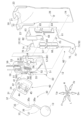
- FIG. 1 is a perspective view of a liquid level detection device according to the present embodiment.
- 2 is an exploded perspective view of the liquid level detection device shown in FIG. 1.
- 3 is a diagram illustrating the mounting member and arm shown in FIG. 2.
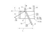
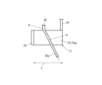
- FIG. 3 is a diagram schematically showing a state in which a part of the arm according to the present embodiment is in contact with a regulating portion.
- FIG. 6 is a diagram schematically showing the positional relationship between a part of the arm and the regulating portion when viewed from the extending direction of the regulating portion in FIG. 5;
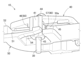
- FIG. 3 is a perspective view of a holder movable restriction section according to the present embodiment.
- FIG. 8 is a diagram illustrating the holder movable restriction section shown in FIG. 7;
- FIG. 8 is an operational diagram of the holder movable restriction section shown in FIG. 7;
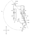
- FIG. 7 is a diagram schematically showing a state in which a part of the arm is in contact with a restriction portion according to a modification of the present embodiment.
- FIGS. 1 and 2 show a liquid level detection device 10 according to an embodiment of the present invention.
- the liquid level detection device 10 is of a float type using a float 13 floating on the liquid surface, and is installed, for example, in a fuel tank that stores liquid fuel such as gasoline.
- the remaining amount of fuel is displayed on a predetermined device, ie, a fuel gauge, based on the detected height of the liquid level.
- the liquid level detection device 10 is mounted on various vehicles (for example, construction machinery) and includes a stop collar 11 attached to the upper part of a fuel tank, a base 20 extending from the stop collar 11 to the lower side of the fuel tank, and a base 20 extending from the stop collar 11 to the lower side of the fuel tank. It has a sender gauge 12 supported by 20 and a float 13 floating on the liquid surface. The float 13 is made of synthetic resin or the like. Note that the liquid level detection device 10 may be attached to a side wall of a fuel tank or the like.
- the arm 30 is made of metal and has a rotating shaft portion 31 passing through the sender gauge 12 and a swinging portion 33 extending from one end 32 of the rotating shaft portion 31.
- the base 20 is L-shaped and consists of a substantially U-shaped bottom 21 welded to the center of the stopper flange 11, and a wall 22 extending downward from the end of the bottom 21.
- a rib 23 is formed at the boundary between the bottom portion 21 and the wall portion 22.
- a positioning convex portion 24 is formed at the lower end of the wall portion 22 , protruding from the wall portion 22 toward the sender gauge 12 and determining the position of the sender gauge 12 .
- the sender gauge 12 includes a swingable metal arm 30, a holder 40 attached to the arm 30, and a resin sender body (frame) 50 that holds the arm 30 via the holder 40.
- the float 13 and the holder 40 are connected (connected) via the arm 30.
- the sender main body 50 includes a flat portion 51 that is inserted into the mounting member 60, a protruding portion 52 that protrudes from the flat portion 51 toward the arm 30, and a housing portion 53 provided above the protruding portion 52.
- a metal terminal 90 is provided in the housing portion 53 by insert molding.
- the caulking portions 91 at the upper ends of the terminals 90 are caulked and connected to the cords (wiring) 59, respectively.
- the terminal 90 has a contact point 92 on the lower end side opposite to the caulking part 91, which is exposed to the outside and comes into contact with an electrode part to be described later. That is, the accommodating portion 53 (sender main body 50) here functions as a resin case that houses the caulking portion 91, which is a part of the terminal 90.
- the mounting member 60 has a substantially U-shape so as to sandwich the sender main body 50, and includes a first surface portion 61 as a main body portion that faces the sender main body 50 and constitutes the main portion of the mounting member 60; It has a second surface section 62 that faces the surface section 61 and a connecting section 63 that connects the lower end of the first surface section 61 and the lower end of the second surface section 62 .
- first to fourth holding portions 64 to 67 which are cut and raised from the first surface portion 61, are formed.
- first locking part 54 of the sender body 50 is locked between the first holding part 64 and the second holding part 65.
- a second locking portion 55 is locked between the third holding portion 66 and the fourth holding portion 67.
- the mounting member 60 has a pair of regulating portions 70 that regulate the movable range R of the arm 30 (see FIG. 4(a)).
- a first restricting portion 71 is formed at the lower end (around the lower left corner) of the first surface portion 61.
- the first restricting portion 71 restricts the movable range R of the arm 30 by contacting the arm 30.
- a second restricting portion 72 is formed at the upper end (around the upper left corner) of the first surface portion 61.
- the second restricting portion 72 restricts the movable range R of the arm 30 by contacting the arm 30.
- the first regulating section 71 and the second regulating section 72 constitute a pair of regulating sections 70 .
- a second through hole 68 is formed in the center of the first surface portion 61, through which the rotating shaft portion 31 passes.
- a positioning hole 25 into which the positioning convex portion 24 fits is formed at the lower end of the first surface portion 61 .
- a third through hole 69 through which the rotating shaft portion 31 passes is formed at the lower end of the second surface portion 62 .
- the wall portion 22 has a fourth through hole 26 through which the rotating shaft portion 31 passes.
- the holder 40 is made of synthetic resin and fixes the arm 30 so that it does not fall off the sender gauge 12.
- the holder 40 includes a ceramic circuit board (substrate) 45 on the surface facing the sender body 50.
- the circuit board 45 has an electrode portion (not shown) that can make contact with the contact point 92 at the lower end of the terminal 90 . Further, the holder 40 here rotates the circuit board 45 in accordance with the movement of the float 13 which follows the liquid level.
- the operation of the liquid level detection device 10 will be explained.
- the liquid level detection device 10 is fixed to the upper part of the fuel tank via a stopper 11.
- the float 13 is displaced downward and the arm 30 to which the float 13 is attached swings.
- the holder 40 also swings (rotates) together with the arm 30.
- the contact 92 slides on the circuit board 45 (above the electrode portion of the circuit board 45) in conjunction with the displacement of the liquid level.
- the position of the electrode part that contacts the contact point 92 provided in the sender body 50 changes in conjunction with the displacement of the liquid level, and the detection signal (resistance output signal) corresponding to the liquid level (position of the float 13) is transmitted to the terminal 90. , and can be output to the fuel gauge via a cord 59 electrically connected to the terminal 90.
- the fuel gauge receives the detection signal and recognizes the position of the float 13, that is, the height of the liquid level.
- the detection section S1 that outputs the detection signal indicating the liquid level is configured by the electrode section provided on the circuit board 45 (holder 40) and the contact point 92 provided on the sender main body 50
- a detection unit S (having a detection section S1 that outputs the detection signal) is constituted by the holder 40 provided with the electrode section, the sender main body 50, the terminal 90 provided with the contact 92, and the cord 59.
- the mounting member 60 has a function as a reinforcing member for mounting the detection unit S (the subassembly) while maintaining its strength to some extent.
- the holder 40 has a substantially J-shaped cross section and includes a sandwiching portion 41 that sandwiches the first through hole 56 .
- a first holding hole 42 and a second holding hole 43 through which the rotating shaft portion 31 passes are formed in the sandwiching portion 41 .
- a first through hole 56 is located between the first holding hole 42 and the second holding hole 43.
- the sandwiching portion 41 is sandwiched between a second through hole 68 and a third through hole 69.
- the holder 40 has a restraining part 44 that restrains the arm 30 connecting the float 13 and the holder 40 (detection unit S) from moving in the axial direction of the rotating shaft part 31.
- the first through hole 56 to the fourth through hole 26 are located on the same axis C.
- the diameter D2 of the second through hole 68 to the diameter D4 of the fourth through hole 26 are approximately equal to the diameter D1 of the first through hole 56.
- the swing portion 33 is formed into an elongated rod shape with a thickness of about several millimeters in a direction perpendicular to the direction in which the swing portion 33 extends, and has a substantially crank shape with a portion thereof bent.
- the swing section 33 includes a first swing section 35 extending from one end 32 of the rotating shaft section 31, a second swing section 36 extending from the tip of the first swing section 35, and a second swing section 36 extending from the tip of the first swing section 35. It has a third swing part 37 extending from the tip of the swing part 36.
- the first swing section 35 is provided on the holder 40 side
- the third swing section 37 is provided on the float 13 side.
- the tip 36a of the second swing section 36 is located closer to the mounting member 60 than the tip 35a of the first swing section 35.
- the third swing part 37 is bent from the tip part 36a at an angle described below so as to be non-parallel to the first swing part 35, and is provided with a first regulation part 71 that is It has an overlapping part 37a that overlaps with the extending part and a non-overlapping part 37b that does not overlap with the first extending part, and the overlapping part 37a and the non-overlapping part 37b extend along a predetermined imaginary line K. are doing.
- a first bending part (to be described later) provided in the first regulating part 71 (a second folding part to be described later provided in the second regulating part 72) It is bent so that the distance from the curved part gradually increases.
- Y1 indicates a first reference line along the extending direction of the second swing section 36 starting from the tip 36a
- Y2 indicates a line opposite to the first direction Y1 starting from the tip 36a.
- a virtual reference line that virtually indicates the direction is shown.
- the above-mentioned virtual line K extends along the extending direction of the third swing portion 37 starting from the tip portion 36a.
- the tip portion 36a (The deflection force acting on the third swing portion 37) becomes a deflection dispersion force F1 that is dispersed by an angle ⁇ .
- the deflection force in the conventional case where the angle ⁇ corresponds to 0 degrees is the deflection force F
- the deflection dispersion force F1 is approximately 0.7 times the deflection force F.
- the first regulating portion 71 has a first extending portion 73 extending toward the swing path of the third swing portion 37.
- a first bent portion 75 is formed at the tip of the first extending portion 73 and is bent toward the movable range R side.
- the third swing portion 37 (arm 30) here is in a restricted state (where movement outside the movable range R is restricted by the movable range restricting surface 73a (see FIG. 6) of the first extending portion 73 (see FIG. 6).
- the above-mentioned overlapping part 37a that overlaps with the first extension part 73 (control part 70) and the above-mentioned overlap part 37a that does not overlap with the first extension part 73 (control part 70) It has a non-polymerized portion 37b.
- the overlapping part 37a (and the non-overlapping part 37b) is different from the first extension part 73 (
- the regulating portion 70) is provided so as to intersect diagonally with respect to the extending direction L of the regulating portion 70).
- the second regulating portion 72 has a second extending portion 74 extending toward the swing trajectory of the third swing portion 37.
- a second bent portion 76 is formed at the tip of the second extending portion 74 and is bent toward the movable range R side.
- the third swing portion 37 (arm 30) here is in a state where movement outside the movable range R is regulated by the movable range regulating surface 74a (see FIG. 6) of the second extension portion 74 (i.e.
- the above-described overlapping portion 37a that overlaps with the second extension portion 74 (restriction portion 70) and the above-mentioned overlapping portion 37a that does not overlap with the second extension portion 74 (restriction portion 70) It has a non-polymerized portion 37b.
- the overlapping part 37a (and the non-overlapping part 37b) is different from the second extension part 74 (
- the regulating portion 70) is provided so as to intersect diagonally with respect to the extending direction L of the regulating portion 70).
- the above-mentioned extending direction L here means the longitudinal direction of the extending portions 73 and 74.
- G is a non-restricting surface located on the opposite side of the movable range restricting surfaces 73a and 74a of the extensions 73 and 74, and this non-restricting surface G is a surface that is located on the opposite side of the movable range restricting surfaces 73a and 74a of the extension portions 73 and 74, and this non-restricting surface G is a surface that prevents the device from functioning normally. In this situation, the third swing section 37 does not come into direct contact with the third swing section 37.
- At least one of the holder 40 and the sender main body 50 is provided with a holder movement restriction portion 80 that restricts the movable range of the holder 40 with respect to the sender main body 50.
- the holder movable restriction part 80 includes a first rotation restraining protrusion 57 provided on the side part 50a of the sender body 50 to restrict rotation of the holder 40 in the first rotational direction with respect to the sender body 50, and a first rotation restraining protrusion 57 provided on the holder 40 and a second rotation inhibiting protrusion 46 that restricts rotation of the holder 40 in the second rotation direction with respect to the sender main body 50.
- the first rotation suppressing protrusion 57 comes into contact with the holder 40, thereby restricting the rotation of the holder 40 in the first rotation direction.
- the second rotation suppressing protrusion 46 comes into contact with the sender body 50, thereby restricting the rotation of the holder 40 in the second rotation direction.
- the first rotation suppressing protrusion 57 is provided on the sender body 50 and the second rotation suppressing protrusion 46 is provided on the holder 40; however, the first rotation suppressing protrusion 57 is provided on the holder 40.
- the second rotation suppressing protrusion 46 may be provided on the sender body 50.
- both the first rotation suppressing protrusion 57 and the second rotation suppressing protrusion 46 may be provided on only one of the holder 40 or the sender main body 50.
- the sandwiching portion 41 of the holder 40 is assembled so as to sandwich the first through hole 56 of the sender main body 50 to form a subassembly.
- This subassembly consisting of the holder 40 and the sender body 50 is assembled to the mounting member 60 and the base 20, and the rotating shaft portion 31 of the arm 30 is inserted into the third through hole 69, the first holding hole 42, the first through hole 56, It is inserted into the second holding hole 43, the second through hole 68, and the fourth through hole 26 (see FIG. 3).
- the holder movable restricting portion 80 is in a state in which the holder 40 rotates in the first rotational direction as shown by the arrow (1), and the pinching portion 41 of the holder 40 is in contact with the first rotation restricting protrusion 57. Thereby, rotation of the holder 40 in the first rotation direction with respect to the sender main body 50 is restricted.
- the holder movable restriction portion 80 is in a state in which the holder 40 shown by the solid line rotates in the second rotation direction as shown by the arrow (2), and the side portion 50a of the sender body 50 is in contact with the second rotation restriction protrusion 46. Thereby, rotation of the holder 40 in the second rotation direction with respect to the sender main body 50 is restricted.
- the movable range of the holder 40 relative to the sender body 50 in the subassembly state becomes R2.
- the movable range R2 of the holder movable restricting portion 80 is wider than the movable range R of the restricting portion 70 (see FIG. 4(a)). Therefore, the contacts 92 of the terminals 90 do not fall off from the circuit board 45 (see FIG. 2) when the subassembly is assembled to the mounting member 60 without hindering the movement of the regulating portion 70 after assembly, and the ease of assembly is improved. can be improved.
- the movable range R2 by the holder movable restriction section 80 is a range from the holder 40 indicated by a solid line to the holder 40 indicated by an imaginary line.
- the float 13 that operates by following the liquid level
- the detection unit S that includes the detection section S1 that outputs the detection signal
- the arm that connects the float 13 and the detection unit S 30 and a mounting member 60 for mounting the detection unit S
- the mounting member 60 has a pair of regulating parts 70 for regulating the movable range R of the arm
- the arm 30 has a pair of regulating parts 70 for regulating the movable range R of the arm 30. It has an overlapping part 37a that overlaps the regulating part 70 in a state of contact, and the overlapping part 37a is provided so as to intersect diagonally with respect to the extending direction L of the regulating part 70.
- the deflection force acting on the tip portion 36a becomes the above-mentioned deflection dispersion force F1, which is smaller than that in the conventional case. Due to this, the tip portion 36a (third swing portion 37) is not easily deformed (swiveled), so the overlapping portion 37a is caused by the movable range regulating surface 73a of the first extension portion 73 (or the second swing portion 37).
- the movable range regulating surface 74a of the extending portion 74 will not restrict the movable range regulating surface 74a) and the movable range regulating surface 73a (or the movable range regulating surface 74a) may climb onto the non-restricting surface G located on the opposite side. Therefore, according to the present invention, it is possible to provide a liquid level detection device that functions normally as a device and can suppress malfunctions.
- the present invention is not limited to the above embodiments and drawings. It is possible to make changes (including deletion of constituent elements) as appropriate without changing the gist of the present invention.
- the detection section that outputs the detection signal indicating the liquid level was composed of the contact 92 and the electrode section formed on the circuit board 45, but the detection section is composed of a magnet and a magnetic detection element.
- the magnetic detection unit may be configured as a magnetic detection unit including:
- a magnet may be disposed at a predetermined location on the holder 40, and a magnetic detection element capable of detecting a change in the magnetic field due to rotation of the holder 40 may be disposed at a predetermined location on the sender body 50.
- this means that the present invention is also applicable to a liquid level detection device that detects the liquid level height by changing magnetism (magnetic field) due to displacement of the float.
- the first regulating part 71 that regulates the movable range R of the arm 30 is formed around the lower left corner of the first surface part 61 in FIG.
- the second regulating part 72 regulating the movable range R of the arm 30 was formed around the corner, the formation positions of the regulating parts 71 and 72 and/or the shapes of the swing parts 35 to 37 are as follows. It goes without saying that it may be changed as appropriate, taking into account the movable range R of the arm 30, for example.
- the second swing part 36 and third swing part 37 of the swing parts 35 to 37 may be bent so as to be parallel to the plate surface of the first surface part 61.
- the first regulating section 71 is provided around the lower right corner of the first surface section 61
- the second regulating section 71 is provided around the lower right corner of the first surface section 61
- the regulating portion 72 is provided around the upper left corner of the first surface portion 61.
- the first regulating section 71 is provided around the corner of the first surface section 61
- the second regulating section 72 is provided around the corner of the first surface section 61. They are provided around other corners of the first surface portion 61 that are approximately diagonal to the corner.
- the first swing section 35 extends from the one end 32 of the rotating shaft section 31.
- the second swing part 36 is a part that extends at a substantially right angle from the tip part 35a
- the third swing part 37 has a clearance with the first surface part 61 that is approximately the same as that of the second swing part 36. This is a portion that is bent diagonally from the tip portion 36a in the open state. Further, the first swing portion 35 is bent toward the first surface portion 61 as it moves away from the one end portion 32 from a position indicated by the symbol P in FIG. 10 as a starting point.
- first swing section 35 here corresponds to a first arm section described in the claims described below
- third swing section 37 corresponds to a first arm section described in the claims described later. This corresponds to the 2nd arm section. Further, in FIG. 10, illustration of the holder 40 is omitted.
- the first swing part 35 is configured to be able to come into contact with the first regulating part 71 as the float 13 moves (rotation of the holder 40), and when the first surface part 61 is viewed straight, the first swing part 35
- the third swing part 37 which is in a non-parallel state with the part 35, is configured to be able to come into contact with the second restriction part 72, similarly to the above-described embodiment.
- 35 parts of the first swing part that overlap with the first regulating part 71 are referred to as first overlapping parts X
- 37 parts of the third swing part that overlaps with the second regulating part 72 are omitted from the illustration.
- the first overlapping portion X provided in the first swing portion 35 and the second overlapping portion provided in the third swing portion 37 constitute the overlapping portion 37a described above. become.
- the pair of restriction parts 70 in the modified example are configured to be able to come into contact with the first overlapping part X of the first swing part 35 as the float 13 moves (rotation of the holder 40).
Landscapes
- Physics & Mathematics (AREA)
- Fluid Mechanics (AREA)
- General Physics & Mathematics (AREA)
- Level Indicators Using A Float (AREA)
Priority Applications (1)
| Application Number | Priority Date | Filing Date | Title |
|---|---|---|---|
| JP2024508151A JPWO2023176769A1 (https=) | 2022-03-14 | 2023-03-13 |
Applications Claiming Priority (4)
| Application Number | Priority Date | Filing Date | Title |
|---|---|---|---|
| JP2022039250 | 2022-03-14 | ||
| JP2022-039250 | 2022-03-14 | ||
| JP2022085831 | 2022-05-26 | ||
| JP2022-085831 | 2022-05-26 |
Publications (1)
| Publication Number | Publication Date |
|---|---|
| WO2023176769A1 true WO2023176769A1 (ja) | 2023-09-21 |
Family
ID=88023772
Family Applications (1)
| Application Number | Title | Priority Date | Filing Date |
|---|---|---|---|
| PCT/JP2023/009593 Ceased WO2023176769A1 (ja) | 2022-03-14 | 2023-03-13 | 液面検出装置 |
Country Status (2)
| Country | Link |
|---|---|
| JP (1) | JPWO2023176769A1 (https=) |
| WO (1) | WO2023176769A1 (https=) |
Citations (3)
| Publication number | Priority date | Publication date | Assignee | Title |
|---|---|---|---|---|
| JPS6262223U (https=) * | 1985-10-08 | 1987-04-17 | ||
| JP2014190953A (ja) * | 2013-03-28 | 2014-10-06 | Denso Corp | 液面検出装置 |
| JP2021099240A (ja) * | 2019-12-20 | 2021-07-01 | 日本精機株式会社 | 液面検出装置 |
-
2023
- 2023-03-13 JP JP2024508151A patent/JPWO2023176769A1/ja active Pending
- 2023-03-13 WO PCT/JP2023/009593 patent/WO2023176769A1/ja not_active Ceased
Patent Citations (3)
| Publication number | Priority date | Publication date | Assignee | Title |
|---|---|---|---|---|
| JPS6262223U (https=) * | 1985-10-08 | 1987-04-17 | ||
| JP2014190953A (ja) * | 2013-03-28 | 2014-10-06 | Denso Corp | 液面検出装置 |
| JP2021099240A (ja) * | 2019-12-20 | 2021-07-01 | 日本精機株式会社 | 液面検出装置 |
Also Published As
| Publication number | Publication date |
|---|---|
| JPWO2023176769A1 (https=) | 2023-09-21 |
Similar Documents
| Publication | Publication Date | Title |
|---|---|---|
| JP4846986B2 (ja) | 密封型燃料レベルセンサ | |
| CN102332648B (zh) | 扁平型导体用电连接器 | |
| CN104380062B (zh) | 液面检测装置 | |
| US10712193B2 (en) | Liquid level detecting device | |
| CN105378424A (zh) | 旋转角度检测装置 | |
| WO2023176769A1 (ja) | 液面検出装置 | |
| JP4093126B2 (ja) | 液面検出装置 | |
| JPWO2018221399A1 (ja) | 液面検出装置 | |
| JP5223269B2 (ja) | 液面検出器 | |
| CN114353909B (zh) | 液位检测装置 | |
| JP5018326B2 (ja) | 液面検出装置 | |
| JP6546619B2 (ja) | 液位検出装置 | |
| JP2021099240A (ja) | 液面検出装置 | |
| JP6554829B2 (ja) | 液面検出装置 | |
| JP7715615B2 (ja) | 液位検出装置 | |
| JP7110861B2 (ja) | 燃料ポンプモジュール | |
| JP7248635B2 (ja) | 金属製の液位検出装置支持体 | |
| JP7015096B2 (ja) | 液位検出装置 | |
| JP7367536B2 (ja) | 液面検出装置 | |
| JP7449257B2 (ja) | 燃料供給装置 | |
| WO2023106025A1 (ja) | 液位検出装置 | |
| JP2004155373A (ja) | アクセルペダル装置 | |
| JP7205319B2 (ja) | 回転角検出装置 | |
| JP6642312B2 (ja) | 液面検出装置 | |
| WO2023074663A1 (ja) | 液面検出装置 |
Legal Events
| Date | Code | Title | Description |
|---|---|---|---|
| 121 | Ep: the epo has been informed by wipo that ep was designated in this application |
Ref document number: 23770724 Country of ref document: EP Kind code of ref document: A1 |
|
| ENP | Entry into the national phase |
Ref document number: 2024508151 Country of ref document: JP Kind code of ref document: A |
|
| NENP | Non-entry into the national phase |
Ref country code: DE |
|
| 122 | Ep: pct application non-entry in european phase |
Ref document number: 23770724 Country of ref document: EP Kind code of ref document: A1 |