WO2023176672A1 - Film optique et système de commande d'angle de visualisation - Google Patents
Film optique et système de commande d'angle de visualisation Download PDFInfo
- Publication number
- WO2023176672A1 WO2023176672A1 PCT/JP2023/009002 JP2023009002W WO2023176672A1 WO 2023176672 A1 WO2023176672 A1 WO 2023176672A1 JP 2023009002 W JP2023009002 W JP 2023009002W WO 2023176672 A1 WO2023176672 A1 WO 2023176672A1
- Authority
- WO
- WIPO (PCT)
- Prior art keywords
- group
- liquid crystal
- light
- layer
- mass
- Prior art date
Links
Images


Classifications
-
- C—CHEMISTRY; METALLURGY
- C08—ORGANIC MACROMOLECULAR COMPOUNDS; THEIR PREPARATION OR CHEMICAL WORKING-UP; COMPOSITIONS BASED THEREON
- C08L—COMPOSITIONS OF MACROMOLECULAR COMPOUNDS
- C08L101/00—Compositions of unspecified macromolecular compounds
- C08L101/12—Compositions of unspecified macromolecular compounds characterised by physical features, e.g. anisotropy, viscosity or electrical conductivity
-
- C—CHEMISTRY; METALLURGY
- C09—DYES; PAINTS; POLISHES; NATURAL RESINS; ADHESIVES; COMPOSITIONS NOT OTHERWISE PROVIDED FOR; APPLICATIONS OF MATERIALS NOT OTHERWISE PROVIDED FOR
- C09K—MATERIALS FOR MISCELLANEOUS APPLICATIONS, NOT PROVIDED FOR ELSEWHERE
- C09K19/00—Liquid crystal materials
- C09K19/04—Liquid crystal materials characterised by the chemical structure of the liquid crystal components, e.g. by a specific unit
- C09K19/38—Polymers
-
- C—CHEMISTRY; METALLURGY
- C09—DYES; PAINTS; POLISHES; NATURAL RESINS; ADHESIVES; COMPOSITIONS NOT OTHERWISE PROVIDED FOR; APPLICATIONS OF MATERIALS NOT OTHERWISE PROVIDED FOR
- C09K—MATERIALS FOR MISCELLANEOUS APPLICATIONS, NOT PROVIDED FOR ELSEWHERE
- C09K19/00—Liquid crystal materials
- C09K19/52—Liquid crystal materials characterised by components which are not liquid crystals, e.g. additives with special physical aspect: solvents, solid particles
- C09K19/60—Pleochroic dyes
-
- G—PHYSICS
- G02—OPTICS
- G02B—OPTICAL ELEMENTS, SYSTEMS OR APPARATUS
- G02B5/00—Optical elements other than lenses
- G02B5/30—Polarising elements
-
- G—PHYSICS
- G02—OPTICS
- G02F—OPTICAL DEVICES OR ARRANGEMENTS FOR THE CONTROL OF LIGHT BY MODIFICATION OF THE OPTICAL PROPERTIES OF THE MEDIA OF THE ELEMENTS INVOLVED THEREIN; NON-LINEAR OPTICS; FREQUENCY-CHANGING OF LIGHT; OPTICAL LOGIC ELEMENTS; OPTICAL ANALOGUE/DIGITAL CONVERTERS
- G02F1/00—Devices or arrangements for the control of the intensity, colour, phase, polarisation or direction of light arriving from an independent light source, e.g. switching, gating or modulating; Non-linear optics
- G02F1/01—Devices or arrangements for the control of the intensity, colour, phase, polarisation or direction of light arriving from an independent light source, e.g. switching, gating or modulating; Non-linear optics for the control of the intensity, phase, polarisation or colour
- G02F1/13—Devices or arrangements for the control of the intensity, colour, phase, polarisation or direction of light arriving from an independent light source, e.g. switching, gating or modulating; Non-linear optics for the control of the intensity, phase, polarisation or colour based on liquid crystals, e.g. single liquid crystal display cells
- G02F1/133—Constructional arrangements; Operation of liquid crystal cells; Circuit arrangements
- G02F1/1333—Constructional arrangements; Manufacturing methods
- G02F1/1335—Structural association of cells with optical devices, e.g. polarisers or reflectors
- G02F1/13363—Birefringent elements, e.g. for optical compensation
-
- G—PHYSICS
- G09—EDUCATION; CRYPTOGRAPHY; DISPLAY; ADVERTISING; SEALS
- G09F—DISPLAYING; ADVERTISING; SIGNS; LABELS OR NAME-PLATES; SEALS
- G09F9/00—Indicating arrangements for variable information in which the information is built-up on a support by selection or combination of individual elements
-
- H—ELECTRICITY
- H10—SEMICONDUCTOR DEVICES; ELECTRIC SOLID-STATE DEVICES NOT OTHERWISE PROVIDED FOR
- H10K—ORGANIC ELECTRIC SOLID-STATE DEVICES
- H10K50/00—Organic light-emitting devices
- H10K50/80—Constructional details
- H10K50/86—Arrangements for improving contrast, e.g. preventing reflection of ambient light
-
- H—ELECTRICITY
- H10—SEMICONDUCTOR DEVICES; ELECTRIC SOLID-STATE DEVICES NOT OTHERWISE PROVIDED FOR
- H10K—ORGANIC ELECTRIC SOLID-STATE DEVICES
- H10K59/00—Integrated devices, or assemblies of multiple devices, comprising at least one organic light-emitting element covered by group H10K50/00
- H10K59/10—OLED displays
Definitions
- the present invention relates to an optical film and a viewing angle control system.
- Patent Document 1 discloses that a retardation film has polarizing films on both sides, the polarizing film includes at least a polarizer, and the absorption axis of the polarizer is oriented substantially perpendicular to the plane of the polarizing film.
- Patent Document 2 describes an optical film including a first anisotropic absorption layer, a first retardation layer, and a second anisotropic absorption layer in this order.
- the present inventor studied a laminate (viewing angle control system) in which the optical films described in Patent Documents 1 and 2 and a polarizer having an absorption axis in the in-plane direction are laminated, and found that the normal of the laminate It has been revealed that when viewed from an angle tilted 25 degrees from the direction, there are cases where the transmittance from the direction (azimuth) where you want to block light increases, and there are cases where coloring is seen in the leaked light.
- the present invention provides a structure in which the transmittance from the direction in which light is desired to be blocked is low when viewed from an angle inclined by 25 degrees from the normal direction of a stacked body in which polarizers having absorption axes in the in-plane direction are stacked, and
- An object of the present invention is to provide an optical film and a viewing angle control system that can suppress coloring of leaked light.
- the present inventors have discovered that by using an optical film having multiple specific light-absorbing anisotropic layers and an intermediate layer that satisfies a predetermined retardation, When viewed from an angle tilted 25 degrees from the normal direction of a stacked stack of polarizers with absorption axes facing inward, the transmittance from the direction you want to block light is low, and the coloring of leaked light is suppressed. They have discovered that it is possible to do this, and have completed the present invention. That is, the present inventor found that the above problem could be solved by the following configuration.
- An optical film comprising a plurality of light-absorbing anisotropic layers containing a dichroic substance and at least one intermediate layer disposed between the plurality of light-absorbing anisotropic layers,
- Each of the plurality of light absorption anisotropic layers has an absorption axis parallel to the thickness direction,
- the thickness of each of the plurality of light absorption anisotropic layers is 3.0 ⁇ m or less
- the total thickness of the plurality of light absorption anisotropic layers is 4.0 ⁇ m or more
- the total value obtained by multiplying the ratio of the dichroic substance content to the mass of the light-absorbing anisotropic layer by the thickness of the light-absorbing anisotropic layer for multiple light-absorbing anisotropic layers is 1.
- a viewing angle control system comprising the optical film according to any one of [1] to [3] and a polarizer having an absorption axis in the in-plane direction.
- [5] It has a display element and the viewing angle control system according to [4], An image display device, wherein a viewing angle control system is disposed on at least one main surface of a display element.
- [6] The image display device according to [5], wherein the plurality of light absorption anisotropic layers included in the viewing angle control system are all arranged closer to the viewing side than the polarizer included in the viewing angle control system.
- the transmittance from the direction in which light is desired to be blocked is low, and It is possible to provide an optical film that can suppress coloring of leaked light, and a viewing angle control system.
- FIG. 1 is a schematic diagram showing an example of a head-mounted display of the present invention.
- FIG. 2 is a schematic diagram showing an example of the configuration of a light guide plate for AR (Augmented Reality) glasses.
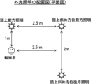
- FIG. 1 is a schematic diagram showing a plan view of an evaluation system for a head-mounted display of the present invention.
- each component may be a substance corresponding to each component, which may be used alone or in combination of two or more.
- the content of the component refers to the total content of the substances used in combination, unless otherwise specified.
- (meth)acrylate is a notation representing “acrylate” or “methacrylate”
- (meth)acrylic is a notation representing “acrylic” or “methacrylic”
- (meth)acrylate is a notation representing "acrylic” or “methacrylic”
- (Meth)acryloyl is a notation representing "acryloyl” or “methacryloyl.”
- liquid crystal composition or “liquid crystal compound” includes a concept that no longer exhibits liquid crystallinity due to curing or the like.
- angular relationships include the range of error allowed in the technical field to which the present invention belongs. Specifically, it means that the exact angle is within a range of less than ⁇ 10°, and the error from the exact angle is preferably within a range of ⁇ 5° or less, and within a range of ⁇ 3° or less. It is more preferable that
- Re( ⁇ ) and Rth( ⁇ ) represent in-plane retardation and retardation in the thickness direction at wavelength ⁇ , respectively.
- the wavelength ⁇ is 550 nm.
- Re ( ⁇ ) and Rth ( ⁇ ) are values measured at wavelength ⁇ using AxoScan (manufactured by Axometrics).
- AxoScan manufactured by Axometrics.
- Re( ⁇ ) R0( ⁇ )
- NAR-4T Abbe refractometer
- ⁇ 589 nm
- DR-M2 multi-wavelength Abbe refractometer
- the average refractive index values of the main optical films are illustrated below: cellulose acylate (1.48), cycloolefin polymer (1.52), polycarbonate (1.59), polymethyl methacrylate (1.49), and polystyrene (1.59).
- the substituent W used in this specification represents the following group.
- Examples of the substituent W include a halogen atom, an alkyl group having 1 to 20 carbon atoms, a halogenated alkyl group having 1 to 20 carbon atoms, a cycloalkyl group having 1 to 20 carbon atoms, and an alkylcarbonyl group having 1 to 10 carbon atoms.
- alkyloxycarbonyl group having 1 to 10 carbon atoms alkylcarbonyloxy group having 1 to 10 carbon atoms, alkylamino group having 1 to 10 carbon atoms, alkylaminocarbonyl group, alkoxy group having 1 to 20 carbon atoms, 1 carbon number ⁇ 20 alkenyl groups, alkynyl groups with 1 to 20 carbon atoms, aryl groups with 1 to 20 carbon atoms, heterocyclic groups (can also be called heterocyclic groups), cyano groups, hydroxy groups, nitro groups, carboxy groups, Aryloxy group, silyloxy group, heterocyclic oxy group, acyloxy group, carbamoyloxy group, alkoxycarbonyloxy group, aryloxycarbonyloxy group, amino group (including anilino group), ammonio group, acylamino group, aminocarbonylamino group, Alkoxycarbonylamino group, aryloxycarbonylamino group, sulfamoyla
- LW represents a single bond or a divalent linking group
- SPW represents a divalent spacer group
- Q represents Q1 or Q2 in the formula (LC) described below
- * represents the bonding position.
- the divalent spacer group represented by SPW includes a linear, branched or cyclic alkylene group having 1 to 50 carbon atoms, or a heterocyclic group having 1 to 20 carbon atoms.
- the hydrogen atom of the above alkylene group and the hydrogen atom of the heterocyclic group are a halogen atom, a cyano group, -Z H , -OH, -OZ H , -COOH, -C(O)Z H , -C(O) OZ H , -OC(O)Z H , -OC(O)OZ H , -NZ H Z H ', -NZ H C(O)Z H ', -NZ H C(O)OZ H ', -C (O)NZ H Z H ', -OC(O)NZ H Z H ', -NZ H C(O)NZ H 'OZ H '', -SH, -SZ H , -C(S)Z H , It may be substituted with -C(O)SZ H , -SC(O)Z H (hereinafter also abbreviated as "SP-H").
- Z H and Z H ' are an alkyl group having 1 to 10 carbon atoms, a halogenated alkyl group, -L-CL (L represents a single bond or a divalent linking group. Specific examples of the divalent linking group) is the same as LW and SPW described above.
- CL represents a crosslinkable group, and examples include a group represented by Q1 or Q2 in the formula (LC) described below, and in formulas (P1) to (P30) described below.
- the crosslinkable group represented by the following is preferable.
- the optical film of the present invention is an optical film having a plurality of light-absorbing anisotropic layers containing a dichroic substance and at least one intermediate layer disposed between the plurality of light-absorbing anisotropic layers.
- the plurality of light absorption anisotropic layers included in the optical film of the present invention all have absorption axes parallel to the thickness direction, and each has a thickness of 3.0 ⁇ m or less, and the total thickness is 4.0 ⁇ m. That's all.
- the optical film of the present invention has a ratio of the dichroic substance content to the mass of the light absorption anisotropic layer (dichroic substance content/mass of the light absorption anisotropic layer) and light absorption anisotropy.
- the total value (hereinafter also abbreviated as "total film thickness in terms of dichroic material") calculated by multiplying the value obtained by multiplying the thickness of the dichroic layer by the thickness of the dichroic layer is 1.10 ⁇ m or more.
- the intermediate layer included in the optical film of the present invention is a layer having an in-plane retardation of 25 nm or less at a wavelength of 550 nm, and an absolute value of retardation in the thickness direction at a wavelength of 550 nm of 25 nm or less.
- each layer is 3.0 ⁇ m or less, the total thickness is 4.0 ⁇ m or more, and the total film thickness in terms of dichroic substance is 1.10 ⁇ m or more, parallel to the thickness direction.
- An optical film that has a plurality of light absorption anisotropic layers (hereinafter referred to as "specific light absorption anisotropic layers” in this paragraph) having a specific absorption axis and an intermediate layer that satisfies a predetermined retardation.
- the plurality of light absorption anisotropic layers included in the optical film of the present invention have a thickness of each layer of 3.0 ⁇ m or less, a total thickness of 4.0 ⁇ m or more, and a total film thickness of 1.10 ⁇ m in terms of dichroic substance.
- This is a light absorption anisotropic layer having an absorption axis parallel to the thickness direction.
- the thickness of each layer of the light absorption anisotropic layer is preferably 1.0 to 3.0 ⁇ m, more preferably 2.0 to 3.0 ⁇ m.
- the total thickness of the light absorption anisotropic layer is preferably 4.0 to 20.0 ⁇ m, more preferably 8.0 to 20.0 ⁇ m.
- the total film thickness of the light-absorbing anisotropic layer in terms of dichroic substances is preferably 1.20 to 5.00 ⁇ m, more preferably 2.00 to 5.00 ⁇ m.
- the thickness of the light absorption anisotropic layer is measured when a cross-sectional section sample is prepared using a microtome and an SEM image is observed using a scanning electron microscope (SEM). It refers to the average value of the thickness at any three points.
- the reason why the transmittance is lower when viewed from a predetermined azimuth angle at an angle of 25 degrees from the normal direction of the laminate in which polarizers having absorption axes in the in-plane direction are stacked is that
- the degree of orientation of each of the plurality of light absorption anisotropic layers is preferably 0.90 or more, more preferably 0.93 or more, and even more preferably 0.95 or more.
- the degree of orientation of the light absorption anisotropic layer is calculated by the following method.
- the transmittance of the light absorption anisotropic layer at a wavelength of 550 nm is measured using AxoScan (manufactured by Axometrics).
- the polar angle which is the angle with respect to the normal direction of the light-absorbing anisotropic layer, was changed in 5° increments from 0 to 60°, and the transmittance at a wavelength of 550 nm at all azimuth angles at each polar angle was measured. Measure.
- the transmittance at the azimuthal and polar angles with the highest transmittance is Tm(0), and in the azimuthal direction with the highest transmittance, from the polar angle with the highest transmittance, Furthermore, the transmittance at an angle where the polar angle is tilted by 40 degrees is Tm (40).
- the absorbance is calculated from the obtained Tm(0) and Tm(40) using the following formula, and A(0) and A(40) are calculated.
- A -log(Tm)
- Tm represents transmittance
- A absorbance
- the light absorption anisotropic layer is preferably a light absorption anisotropic layer containing a dichroic substance, and is preferably a light absorption anisotropic layer containing a dichroic substance and a liquid crystal compound. More preferably, it is a layer in which the alignment state of the liquid crystal compound and the dichroic substance is fixed.
- a light absorption anisotropic layer can be formed from a liquid crystal composition containing a liquid crystal compound and a dichroic substance.
- the liquid crystal composition may contain an aligning agent, a solvent, a polymerization initiator, a polymerizable compound, an interface improver, and other additives. Each component will be explained below.
- the liquid crystal composition contains a liquid crystal compound.
- the dichroic substance can be oriented with a high degree of orientation while suppressing precipitation of the dichroic substance.
- liquid crystal compounds contained in liquid crystal compositions can generally be classified into rod-like types and disc-like types based on their shapes.
- the liquid crystal compound is preferably a liquid crystal compound that does not exhibit dichroism in the visible region. In the following description, "the degree of orientation of the light-absorbing anisotropic layer formed is higher" is also referred to as "the effect of the present invention is more excellent.”
- liquid crystal compound both low-molecular liquid crystal compounds and high-molecular liquid crystal compounds can be used.
- low-molecular liquid crystal compound refers to a liquid crystal compound that does not have repeating units in its chemical structure.
- polymer liquid crystal compound refers to a liquid crystal compound having repeating units in its chemical structure.
- the low-molecular liquid crystal compound include liquid crystal compounds described in JP-A No. 2013-228706.
- the polymeric liquid crystal compound include thermotropic liquid crystalline polymers described in JP-A No. 2011-237513.
- the polymeric liquid crystal compound may have a crosslinkable group (for example, an acryloyl group and a methacryloyl group) at the terminal.
- the liquid crystal compound is preferably a rod-shaped liquid crystal compound, and more preferably a polymeric liquid crystal compound because the effects of the present invention are easily manifested.
- the liquid crystal compounds may be used alone or in combination of two or more.
- the liquid crystal compound preferably contains a polymeric liquid crystal compound, and particularly preferably contains both a polymeric liquid crystal compound and a low molecular weight liquid crystal compound, in order to obtain more excellent effects of the present invention.
- the liquid crystal compound preferably includes a liquid crystal compound represented by formula (LC) or a polymer thereof.
- the liquid crystal compound represented by formula (LC) or its polymer is a compound that exhibits liquid crystallinity.
- the liquid crystallinity may be a nematic phase or a smectic phase, or may exhibit both a nematic phase and a smectic phase, and preferably exhibits at least a nematic phase.
- the smectic phase may be a higher order smectic phase.
- the higher-order smectic phases here include smectic B phase, smectic D phase, smectic E phase, smectic F phase, smectic G phase, smectic H phase, smectic I phase, smectic J phase, smectic K phase, smectic L phase, Among them, smectic B phase, smectic F phase, and smectic I phase are preferable.
- the smectic liquid crystal phase exhibited by the liquid crystal compound is one of these higher-order smectic liquid crystal phases, a light absorption anisotropic layer with a higher degree of orientational order can be produced.
- a light absorption anisotropic layer made from a high-order smectic liquid crystal phase with a high degree of orientational order shows a Bragg peak derived from a higher-order structure such as a hexatic phase or a crystalline phase in X-ray diffraction measurements.
- the above-mentioned Bragg peak is a peak derived from the plane periodic structure of molecular orientation, and according to the liquid crystal composition of the present invention, a light absorption anisotropic layer with a periodic interval of 3.0 to 5.0 ⁇ can be obtained. I can do it.
- Q1 and Q2 each independently represent a hydrogen atom, a halogen atom, a linear, branched or cyclic alkyl group having 1 to 20 carbon atoms, an alkoxy group having 1 to 20 carbon atoms, or a C1 to 20 alkyl group.
- R P is a hydrogen atom, a halogen atom, a linear, branched, or cyclic alkylene group having 1 to 10 carbon atoms, or a halogenated alkyl group having 1 to 20 carbon atoms.
- an alkoxy group having 1 to 20 carbon atoms an alkenyl group having 1 to 20 carbon atoms, an alkynyl group having 1 to 20 carbon atoms, an aryl group having 1 to 20 carbon atoms, a heterocyclic group (which can also be called a heterocyclic group) , cyano group, hydroxy group, nitro group, carboxy group, aryloxy group, silyloxy group, heterocyclic oxy group, acyloxy group, carbamoyloxy group, alkoxycarbonyloxy group, aryloxycarbonyloxy group, amino group (including anilino group) ), ammonio group, acylamino group, aminocarbonylamino group, alkoxycarbonylamino group, aryloxycarbonylamino group, sulfamoylamino group, alkyl or arylsulfonylamino group, mercapto group, alkylthio group, arylthio group, heterocycl
- Preferred embodiments of the crosslinkable group include radically polymerizable groups and cationically polymerizable groups.
- examples of the radically polymerizable group include a vinyl group represented by the above formula (P-1), a butadiene group represented by the above formula (P-2), and a (meth)acrylic group represented by the above formula (P-4).
- the cationically polymerizable group is a vinyl ether group represented by the above formula (P-18), an epoxy group represented by the above formula (P-19), or an oxetanyl group represented by the above formula (P-20). , is preferable.
- S1 and S2 each independently represent a divalent spacer group, and a preferred embodiment of S1 and S2 is the same structure as SPW in formula (W1) above, so the explanation thereof is omitted. do.
- MG represents a mesogenic group described later.
- the mesogenic group represented by MG is a group representing the main skeleton of liquid crystal molecules that contributes to liquid crystal formation. Liquid crystal molecules exhibit liquid crystallinity, which is an intermediate state (mesophase) between a crystalline state and an isotropic liquid state.
- the mesogenic group represented by MG preferably contains 2 to 10 cyclic structures, more preferably 3 to 7 cyclic structures. Specific examples of the cyclic structure include aromatic hydrocarbon groups, heterocyclic groups, and alicyclic groups.
- the mesogenic group represented by MG is the following formula (MG-A) or the following formula, from the viewpoint of expression of liquid crystallinity, adjustment of liquid crystal phase transition temperature, raw material availability and synthesis suitability, and the effects of the present invention.
- a group represented by (MG-B) is preferred, and a group represented by formula (MG-B) is more preferred.
- A1 is a divalent group selected from the group consisting of an aromatic hydrocarbon group, a heterocyclic group, and an alicyclic group. These groups may be substituted with a substituent such as the above-mentioned substituent W.
- the divalent group represented by A1 is preferably a 4- to 15-membered ring. Further, the divalent group represented by A1 may be a monocyclic ring or a condensed ring group. * represents the bonding position with S1 or S2.
- Examples of the divalent aromatic hydrocarbon group represented by A1 include phenylene group, naphthylene group, fluorene-diyl group, anthracene-diyl group, and tetracene-diyl group. From the viewpoint of properties and the like, phenylene groups and naphthylene groups are preferred.
- the divalent heterocyclic group represented by A1 may be aromatic or non-aromatic, but from the viewpoint of further improving the degree of orientation, a divalent aromatic heterocyclic group is preferable.
- Atoms other than carbon constituting the divalent aromatic heterocyclic group include a nitrogen atom, a sulfur atom, and an oxygen atom.
- the aromatic heterocyclic group has a plurality of atoms constituting a ring other than carbon, these may be the same or different.
- divalent aromatic heterocyclic groups include pyridylene group (pyridine-diyl group), pyridazine-diyl group, imidazole-diyl group, thienylene (thiophene-diyl group), quinolylene group (quinoline-diyl group), etc.
- isoquinolylene group isoquinoline-diyl group
- oxazole-diyl group isoquinoline-diyl group
- thiazole-diyl group isoxadiazole-diyl group
- benzothiazole-diyl group benzothiadiazole-diyl group
- phthalimido-diyl group isoquinoline-diyl group
- thienothiazole-diyl group isoxazole-diyl group
- thiazole-diyl group isoxadiazole-diyl group
- benzothiazole-diyl group isnzothiadiazole-diyl group
- phthalimido-diyl group is thienothiazole-diyl group
- thiazolothiazole-diyl group isothiophene-diyl group
- D 1 represents -S-, -O-, or NR 11 -
- R 11 represents a hydrogen atom or an alkyl group having 1 to 6 carbon atoms
- Y 1 represents an aromatic hydrocarbon group having 6 to 12 carbon atoms or an aromatic heterocyclic group having 3 to 12 carbon atoms
- Z 1 , Z 2 , and Z 3 each independently represent a hydrogen atom or a carbon number
- Aliphatic hydrocarbon group having 1 to 20 carbon atoms, alicyclic hydrocarbon group having 3 to 20 carbon atoms, monovalent aromatic hydrocarbon group having 6 to 20 carbon atoms, halogen atom, cyano group, nitro group, -NR 12 R 13 or -SR 12 , Z 1 and Z 2 may be combined with each other to form an aromatic ring or an aromatic heterocycle
- R 12 and R 13 each independently represent a hydrogen atom or a carbon atom having 1 -6 alkyl group
- J 1 and J 2 are each independently -O-
- Jx and Jy may be combined to form a ring
- D 2 represents a hydrogen atom or an alkyl group having 1 to 6 carbon atoms which may have a substituent.
- Y 1 when Y 1 is an aromatic hydrocarbon group having 6 to 12 carbon atoms, it may be monocyclic or polycyclic. When Y 1 is an aromatic heterocyclic group having 3 to 12 carbon atoms, it may be monocyclic or polycyclic.
- J 1 and J 2 when J 1 and J 2 represent -NR 21 -, as the substituent for R 21 , for example, the descriptions in paragraphs 0035 to 0045 of JP 2008-107767 A can be referred to, This content is incorporated herein.
- R' represents a substituent, and for the substituent, for example, the descriptions in paragraphs [0035] to [0045] of JP-A No. 2008-107767 can be referred to, and -NZ A1 Z A2 (Z A1 and Z A2 are each independently , represents a hydrogen atom, an alkyl group or an aryl group) are preferred.
- divalent alicyclic group represented by A1 include a cyclopentylene group and a cyclohexylene group, and carbon atoms include -O-, -Si(CH 3 ) 2 -, -N( Z)-(Z represents hydrogen, an alkyl group having 1 to 4 carbon atoms, a cycloalkyl group, an aryl group, a cyano group, or a halogen atom), -C(O)-, -S-, -C It may be substituted with (S)-, -S(O)-, -SO 2 -, or a combination of two or more of these groups.
- a1 represents an integer from 2 to 10.
- a plurality of A1s may be the same or different.
- A2 and A3 are each independently a divalent group selected from the group consisting of an aromatic hydrocarbon group, a heterocyclic group, and an alicyclic group. Specific examples and preferred embodiments of A2 and A3 are the same as A1 in formula (MG-A), so their explanation will be omitted.
- a2 represents an integer from 1 to 10, multiple A2's may be the same or different, and multiple LA1's may be the same or different. It is more preferable that a2 is 2 or more because the effect of the present invention is more excellent.
- LA1 is a single bond or a divalent linking group.
- LA1 is a divalent linking group
- a2 is 2 or more
- at least one of the plurality of LA1 is a divalent linking group.
- the divalent linking group represented by LA1 is the same as LW, so its explanation will be omitted.
- MG include the following structures, in which hydrogen atoms on aromatic hydrocarbon groups, heterocyclic groups, and alicyclic groups are substituted with the above-mentioned substituent W. Good too.
- liquid crystal compound represented by formula (LC) is a low-molecular liquid crystal compound
- preferred embodiments of the cyclic structure of the mesogenic group MG include a cyclohexylene group, a cyclopentylene group, a phenylene group, a naphthylene group, and a fluorene-diyl group.
- Preferred embodiments of the substituent W having a mesogenic structure include a halogen atom, a halogenated alkyl group, a cyano group, a hydroxy group, a nitro group, a carboxy group, an alkoxy group having 1 to 10 carbon atoms, and an alkylcarbonyl group having 1 to 10 carbon atoms.
- LW is Examples include a group in which SPW is a divalent spacer group, and Q is a crosslinkable group represented by (P1) to (P30) described above. Examples of the crosslinkable group include a vinyl group.
- butadiene group (meth)acrylic group, (meth)acrylamide group, vinyl acetate group, fumaric acid ester group, styryl group, vinylpyrrolidone group, maleic anhydride, maleimide group, vinyl ether group, epoxy group, oxetanyl group are preferred. .
- a preferred embodiment of the divalent spacer groups S1 and S2 is the same as that of SPW above, and therefore the description thereof will be omitted.
- the number of carbon atoms in the spacer group (the number of atoms when this carbon is replaced with "SP-C") is preferably 6 or more, more preferably 8 or more. .
- liquid crystal compound represented by formula (LC) is a low-molecular liquid crystal compound
- a plurality of low-molecular liquid crystal compounds may be used in combination, preferably 2 to 6 types are used together, and 2 to 4 types are used in combination. is even more preferable.
- the solubility can be improved and the phase transition temperature of the liquid crystal composition can be adjusted.
- low-molecular liquid crystal compounds include compounds represented by the following formulas (LC-1) to (LC-77), but the low-molecular liquid crystal compounds are not limited to these.
- the polymeric liquid crystal compound is preferably a homopolymer or copolymer containing the repeating units described below, and may be any polymer such as a random polymer, block polymer, graft polymer, or star polymer.
- the polymeric liquid crystal compound preferably contains a repeating unit represented by formula (1) (hereinafter also referred to as “repeat unit (1)").
- PC1 represents the main chain of the repeating unit
- L1 represents a single bond or a divalent linking group
- SP1 represents a spacer group
- MG1 represents the mesogenic group MG in the above formula (LC).
- T1 represents a terminal group.
- Examples of the main chain of the repeating unit represented by PC1 include groups represented by formulas (P1-A) to (P1-D), among which the monomers used as raw materials are diverse and easy to handle. From this viewpoint, a group represented by the following formula (P1-A) is preferable.
- R 11 , R 12 , R 13 , and R 14 are each independently a hydrogen atom, a halogen atom, a cyano group, an alkyl group having 1 to 10 carbon atoms, or a carbon number Represents 1 to 10 alkoxy groups.
- the alkyl group may be a linear or branched alkyl group, or may be an alkyl group having a cyclic structure (cycloalkyl group). Further, the number of carbon atoms in the alkyl group is preferably 1 to 5.
- the group represented by formula (P1-A) is preferably one unit of a partial structure of a poly(meth)acrylic ester obtained by polymerization of a (meth)acrylic ester.
- the group represented by formula (P1-B) is preferably an ethylene glycol unit formed by ring-opening polymerization of the epoxy group of a compound having an epoxy group.
- the group represented by formula (P1-C) is preferably a propylene glycol unit formed by ring-opening polymerization of the oxetane group of a compound having an oxetane group.
- the group represented by formula (P1-D) is preferably a siloxane unit of a polysiloxane obtained by polycondensation of a compound having at least one of an alkoxysilyl group and a silanol group.
- examples of the compound having at least one of an alkoxysilyl group and a silanol group include a compound having a group represented by the formula SiR 14 (OR 15 ) 2 -.
- R 14 has the same meaning as R 14 in (P1-D), and each of the plurality of R 15s independently represents a hydrogen atom or an alkyl group having 1 to 10 carbon atoms.
- the divalent linking group represented by L1 is the same divalent linking group as LW in the above formula (W1), and preferred embodiments include -C(O)O-, -OC(O)-, - Examples include O-, -S-, -C(O)NR 16 -, -NR 16 C(O)-, -S(O) 2 -, and -NR 16 R 17 -.
- R 16 and R 17 each independently represent a hydrogen atom or an alkyl group having 1 to 6 carbon atoms which may have a substituent (eg, the above-mentioned substituent W).
- the left-hand bond bonds with PC1 and the right-hand bond bonds with SP1.
- L1 is preferably a group represented by -C(O)O- or -C(O)NR 16 -.
- PC1 is a group represented by formulas (P1-B) to (P1-D)
- L1 is preferably a single bond.
- the spacer group represented by SP1 represents the same group as S1 and S2 in the above formula (LC), and is selected from the group consisting of an oxyethylene structure, an oxypropylene structure, a polysiloxane structure, and a fluorinated alkylene structure from the viewpoint of the degree of orientation. or a linear or branched alkylene group having 2 to 20 carbon atoms.
- the above alkylene group is -O-, -S-, -O-CO-, -CO-O-, -O-CO-O-, -O-CNR- (R has 1 to 10 carbon atoms) represents an alkyl group) or -S(O) 2 -.
- the spacer group represented by SP1 is at least one selected from the group consisting of an oxyethylene structure, an oxypropylene structure, a polysiloxane structure, and a fluorinated alkylene structure, for reasons such as easy expression of liquid crystallinity and availability of raw materials. More preferably, it is a group containing a species structure.
- the oxyethylene structure represented by SP1 is preferably a group represented by *-(CH 2 -CH 2 O) n1 -*.
- n1 represents an integer from 1 to 20, and * represents the bonding position with L1 or MG1.
- n1 is preferably an integer of 2 to 10, more preferably 2 to 6, and most preferably 2 to 4, because the effects of the present invention are better.
- the oxypropylene structure represented by SP1 is preferably a group represented by *-(CH(CH 3 )-CH 2 O) n2 -*.
- n2 represents an integer of 1 to 3, and * represents the bonding position with L1 or MG1.
- the polysiloxane structure represented by SP1 is preferably a group represented by *-(Si(CH 3 ) 2 -O) n3 -*.
- n3 represents an integer from 6 to 10
- * represents the bonding position with L1 or MG1.
- the fluorinated alkylene structure represented by SP1 is preferably a group represented by *-(CF 2 -CF 2 ) n4 -*.
- n4 represents an integer from 6 to 10 and * represents the bonding position with L1 or MG1.
- the terminal group represented by T1 includes a hydrogen atom, a halogen atom, a cyano group, a nitro group, a hydroxyl group, -SH, a carboxyl group, a boronic acid group, -SO 3 H, -PO 3 H 2 , -NR 11 R 12 ( R 11 and R 12 each independently represent a hydrogen atom, a substituted or unsubstituted alkyl group having 1 to 10 carbon atoms, a cycloalkyl group, or an aryl group), an alkyl group having 1 to 10 carbon atoms, or an alkyl group having 1 to 10 carbon atoms; 10 alkoxy group, alkylthio group having 1 to 10 carbon atoms, alkoxycarbonyloxy group having 1 to 10 carbon atoms, acyloxy group having 1 to 10 carbon atoms, acylamino group having 1 to 10 carbon atoms, alkoxy having 1 to 10 carbon atoms Carbonyl group, alkoxycarbony
- Examples of the crosslinkable group-containing group include the above-mentioned -L-CL.
- L represents a single bond or a connecting group. Specific examples of the linking group are the same as those for LW and SPW described above.
- CL represents a crosslinkable group, and examples thereof include the group represented by Q1 or Q2 described above, and groups represented by formulas (P1) to (P30) described above are preferred.
- T1 may be a combination of two or more of these groups.
- T1 is preferably an alkoxy group having 1 to 10 carbon atoms, more preferably an alkoxy group having 1 to 5 carbon atoms, and even more preferably a methoxy group because the effects of the present invention are more excellent.
- the number of atoms in the main chain of T1 is preferably from 1 to 20, more preferably from 1 to 15, even more preferably from 1 to 10, particularly preferably from 1 to 7, because the effect of the present invention is more excellent.
- the number of atoms in the main chain of T1 is 20 or less, the degree of orientation of the light absorption anisotropic layer is further improved.
- the "main chain" in T1 means the longest molecular chain bonded to M1, and hydrogen atoms are not counted in the number of atoms in the main chain of T1. For example, when T1 is an n-butyl group, the number of atoms in the main chain is 4, and when T1 is a sec-butyl group, the number of atoms in the main chain is 3.
- the content of the repeating unit (1) is preferably 40 to 100% by mass, more preferably 50 to 95% by mass, based on all repeating units (100% by mass) possessed by the polymeric liquid crystal compound.
- the repeating unit (1) may be contained singly or in combination of two or more types in the polymeric liquid crystal compound. When two or more types of repeating units (1) are included, the content of repeating units (1) above means the total content of repeating units (1).
- ) is 4 or more, and from the viewpoint of further improving the degree of orientation of the light absorption anisotropic layer, it is preferably 4.25 or more, and more preferably 4.5 or more. Further, the upper limit value of the difference is preferably 15 or less, more preferably 12 or less, and even more preferably 10 or less, from the viewpoint of adjusting the liquid crystal phase transition temperature and synthesis suitability.
- the logP value is an index expressing the hydrophilicity and hydrophobicity of a chemical structure, and is sometimes called a hydrophilic-hydrophobic parameter. The logP value can be calculated using software such as ChemBioDraw Ultra or HSPiP (Ver.
- logP 1 means the logP values of PC1, L1, and SP1.
- LogP value of PC1, L1, and SP1 means the logP value of the structure that integrates PC1, L1, and SP1, and does not mean the sum of the logP values of PC1, L1, and SP1.
- logP 1 is calculated by inputting a series of structural formulas from PC1 to SP1 in formula (1) into the above software.
- the structure of the group represented by PC1 for example, the above formula (P1-A ) to formula (P1-D), etc.
- the structure of a group that can become PC1 after polymerizing the monomer used to obtain the repeating unit represented by formula (1) Good too.
- logP 1 may be lower than logP 2 or higher than logP 2 as long as the difference from logP 2 described above is 4 or more.
- the logP value (logP 2 described above) of a general mesogenic group tends to be within the range of 4 to 6.
- the value of logP 1 is preferably 1 or less, and more preferably 0 or less.
- the value of logP 1 is preferably 8 or more, more preferably 9 or more.
- the logP value of SP1 in the above formula (1) is 0.7 or less. is preferable, and 0.5 or less is more preferable.
- the logP value of SP1 in the above formula (1) is 3. 7 or more is preferable, and 4.2 or more is more preferable.
- structures having a logP value of 1 or less include, for example, an oxyethylene structure and an oxypropylene structure.
- Examples of the structure having a logP value of 6 or more include a polysiloxane structure and a fluorinated alkylene structure.
- the polymeric liquid crystal compound preferably contains a repeating unit having electron-donating and/or electron-withdrawing properties at the terminal. More specifically, a repeating unit (21) having a mesogenic group and an electron-withdrawing group having a ⁇ p value of greater than 0 present at its terminal, and a repeating unit (21) having a mesogenic group and an electron-withdrawing group having a ⁇ p value of 0 or less present at its terminal. It is more preferable to include a repeating unit (22) having a group.
- the polymeric liquid crystal compound contains the repeating unit (21) and the repeating unit (22), compared to the case where it contains only either the above repeating unit (21) or the above repeating unit (22), this The degree of orientation of the light absorption anisotropic layer formed using this method is improved. Although the details of this reason are not clear, it is generally estimated as follows. In other words, the opposite dipole moments generated in the repeating unit (21) and the repeating unit (22) interact intermolecularly, and the interaction in the short axis direction of the mesogenic group becomes stronger, resulting in the formation of a liquid crystal. It is presumed that the alignment direction becomes more uniform, and as a result, the degree of order of the liquid crystal increases. This improves the orientation of the dichroic substance, so it is presumed that the degree of orientation of the formed light-absorbing anisotropic layer increases. Note that the above repeating units (21) and (22) may be repeating units represented by the above formula (1).
- the repeating unit (21) has a mesogenic group and an electron-withdrawing group having a ⁇ p value of greater than 0, which is present at the end of the mesogenic group.
- the electron-withdrawing group is located at the end of the mesogenic group and has a ⁇ p value of greater than 0.
- Examples of the electron-withdrawing group (group having a ⁇ p value greater than 0) include a group represented by EWG in the formula (LCP-21) described below, and specific examples thereof are also the same.
- the ⁇ p value of the electron-withdrawing group is preferably 0.3 or more, more preferably 0.4 or more, from the viewpoint of being larger than 0 and increasing the degree of orientation of the light-absorbing anisotropic layer.
- the upper limit of the ⁇ p value of the electron-withdrawing group is preferably 1.2 or less, more preferably 1.0 or less, from the viewpoint of excellent alignment uniformity.
- the ⁇ p value is Hammett's substituent constant ⁇ p value (also simply abbreviated as " ⁇ p value”), which numerically expresses the effect of a substituent on the acid dissociation equilibrium constant of substituted benzoic acid. This is a parameter indicating the strength of electron-withdrawing and electron-donating properties.
- the Hammett substituent constant ⁇ p value in this specification means the substituent constant ⁇ when the substituent is located at the para position of benzoic acid.
- the Hammett substituent constant ⁇ p value of each group in this specification the value described in the document "Hansch et al., Chemical Reviews, 1991, Vol, 91, No. 2, 165-195" is adopted.
- Hammett's substituent constant ⁇ p value For groups for which Hammett's substituent constant ⁇ p value is not shown in the above literature, the pKa of benzoic acid is determined using the software "ACD/ChemSketch (ACD/Labs 8.00 Release Product Version: 8.08) Hammett's substituent constant ⁇ p value can be calculated based on the difference between pKa and pKa of the benzoic acid derivative having a substituent at the para position.
- the repeating unit (21) is not particularly limited as long as it has a mesogenic group in the side chain and an electron-withdrawing group with a ⁇ p value larger than 0 present at the end of the mesogenic group, but it can be used in the light absorption anisotropic layer. It is preferable to use a repeating unit represented by the following formula (LCP-21) because the degree of orientation of the repeating unit becomes higher.
- PC21 represents the main chain of the repeating unit, more specifically represents the same structure as PC1 in the above formula (1), and L21 represents a single bond or a divalent linking group.
- SP21A and SP21B each independently represent a single bond or a spacer group, and a specific example of the spacer group is SP1 in the above formula (1).
- MG21 represents a mesogenic structure, more specifically a mesogenic group MG in the above formula (LC), and EWG represents an electron-withdrawing group with a ⁇ p value greater than 0.
- the spacer group represented by SP21A and SP21B represents a group similar to the above formulas S1 and S2, and has at least one structure selected from the group consisting of an oxyethylene structure, an oxypropylene structure, a polysiloxane structure, and a fluorinated alkylene structure. or a linear or branched alkylene group having 2 to 20 carbon atoms.
- the alkylene group may include -O-, -O-CO-, -CO-O-, or -O-CO-O-.
- the spacer group represented by SP1 is at least one selected from the group consisting of an oxyethylene structure, an oxypropylene structure, a polysiloxane structure, and a fluorinated alkylene structure, for reasons such as easy expression of liquid crystallinity and availability of raw materials.
- it includes a species structure.
- SP21B is preferably a single bond or a linear or branched alkylene group having 2 to 20 carbon atoms.
- the alkylene group may include -O-, -O-CO-, -CO-O-, or -O-CO-O-.
- the spacer group represented by SP21B is preferably a single bond because the degree of orientation of the light-absorbing anisotropic layer becomes higher.
- repeating unit 21 preferably has a structure in which EWG, which is an electron-withdrawing group in formula (LCP-21), is directly connected to MG21, which is a mesogenic group in formula (LCP-21).
- EWG represents an electron-withdrawing group with a ⁇ p value greater than 0.
- Examples of electron-withdrawing groups with a ⁇ p value greater than 0 include ester groups (specifically, groups represented by *-C(O) ORE ), (meth)acryloyl groups, and (meth)acryloyloxy groups.
- R E represents an alkyl group having 1 to 20 carbon atoms (preferably 1 to 4 carbon atoms, more preferably 1 to 2 carbon atoms).
- R F each independently represents a hydrogen atom or an alkyl group having 1 to 20 carbon atoms (preferably 1 to 4 carbon atoms, more preferably 1 to 2 carbon atoms).
- EWG is a group represented by *-C(O)O- RE , a (meth)acryloyloxy group, a cyano group, or a nitro group, since the effects of the present invention are more effectively exhibited. , is preferable.
- the content of the repeating unit (21) is determined from the viewpoint of uniformly aligning the polymeric liquid crystal compound and the dichroic substance while maintaining a high degree of orientation of the light-absorbing anisotropic layer. It is preferably 60% by mass or less, more preferably 50% by mass or less, particularly preferably 45% by mass or less, based on the unit (100% by mass).
- the lower limit of the content of the repeating unit (21) is preferably 1% by mass or more based on all repeating units (100% by mass) possessed by the polymeric liquid crystal compound, in order to better exhibit the effects of the present invention. More preferably, the content is 3% by mass or more.
- each repeating unit contained in the polymeric liquid crystal compound is calculated based on the amount (mass) of each monomer used to obtain each repeating unit.
- the repeating unit (21) may be contained singly or in combination of two or more types in the polymeric liquid crystal compound.
- the polymer liquid crystal compound contains two or more types of repeating units (21)
- there are advantages such as improved solubility of the polymer liquid crystal compound in a solvent and easier adjustment of the liquid crystal phase transition temperature.
- the total amount thereof is preferably within the above range.
- a repeating unit (21) that does not contain a crosslinkable group in EWG and a repeating unit (21) that contains a polymerizable group in EWG may be used together. This further improves the curability of the light-absorbing anisotropic layer.
- crosslinkable groups include vinyl group, butadiene group, (meth)acrylic group, (meth)acrylamide group, vinyl acetate group, fumaric acid ester group, styryl group, vinylpyrrolidone group, maleic anhydride, maleimide group, and vinyl ether.
- a group, an epoxy group, and an oxetanyl group are preferred.
- the content of the repeating unit (21) containing a polymerizable group in the EWG should be adjusted to the total repeating unit (100 mass %), preferably 1 to 30% by mass.
- repeating unit (21) An example of the repeating unit (21) is shown below, but the repeating unit (21) is not limited to the following repeating units.
- the present inventors found that the electron-withdrawing property of the repeating unit (21) When the electron-withdrawing property of the group is strong (that is, when the ⁇ p value is large), if the content of the repeating unit (21) is lowered, the degree of orientation of the light-absorbing anisotropic layer will be higher; ) If the electron-withdrawing property of the electron-withdrawing group in I found it to be high. Although the details of this reason are not clear, it is generally estimated as follows.
- the degree of orientation of the oriented layer becomes higher.
- the ⁇ p value of the electron-withdrawing group (EWG in formula (LCP-21)) in the repeating unit (21) and the content ratio (based on mass) of the repeating unit (21) in the polymeric liquid crystal compound is preferably 0.020 to 0.150, more preferably 0.050 to 0.130, particularly preferably 0.055 to 0.125. If the product is within the above range, the degree of orientation of the light-absorbing anisotropic layer will be higher.
- the repeating unit (22) has a mesogenic group and a group having a ⁇ p value of 0 or less, which is present at the end of the mesogenic group. Since the polymeric liquid crystal compound has the repeating unit (22), the polymeric liquid crystal compound and the dichroic substance can be uniformly aligned.
- the mesogenic group is a group representing the main skeleton of a liquid crystal molecule that contributes to liquid crystal formation, and details are as explained below for MG in formula (LCP-22), and specific examples thereof are also the same.
- the above group is located at the end of the mesogenic group and has a ⁇ p value of 0 or less.
- the above groups include hydrogen atoms whose ⁇ p value is 0, and groups represented by T22 (electronic (donating group).
- groups represented by T22 electroactive (donating group).
- specific examples of groups (electron donating groups) with a ⁇ p value smaller than 0 are the same as T22 in formula (LCP-22) described below.
- the ⁇ p value of the above group is 0 or less, and is preferably smaller than 0, more preferably -0.1 or less, and particularly preferably -0.2 or less, from the viewpoint of more excellent alignment uniformity.
- the lower limit of the ⁇ p value of the above group is preferably -0.9 or more, more preferably -0.7 or more.
- the repeating unit (22) is not particularly limited as long as it has a mesogenic group in the side chain and a group having a ⁇ p value of 0 or less that is present at the end of the mesogenic group, but the uniformity of the alignment of the liquid crystal is improved.
- PCP-22 a repeating unit represented by the following formula (PCP-22), which does not correspond to the repeating unit represented by the above formula (LCP-21).
- PC22 represents the main chain of the repeating unit, more specifically represents the same structure as PC1 in the above formula (1), and L22 represents a single bond or a divalent linking group.
- SP22 represents a spacer group, more specifically represents the same structure as SP1 in the above formula (1)
- MG22 represents the same structure as SP1 in the above formula (1).
- It represents a mesogenic structure, more specifically a structure similar to the mesogenic group MG in the above formula (LC)
- T22 represents an electron-donating group having a Hammett substituent constant ⁇ p value of less than 0.
- T22 represents an electron donating group with a ⁇ p value of less than 0.
- the electron donating group having a ⁇ p value of less than 0 include a hydroxy group, an alkyl group having 1 to 10 carbon atoms, an alkoxy group having 1 to 10 carbon atoms, and an alkylamino group having 1 to 10 carbon atoms.
- the "main chain" in T22 means the longest molecular chain bonded to MG22, and hydrogen atoms are not counted in the number of atoms in the main chain of T22. For example, when T22 is an n-butyl group, the number of atoms in the main chain is 4, and when T22 is a sec-butyl group, the number of atoms in the main chain is 3.
- repeating unit (22) An example of the repeating unit (22) is shown below, but the repeating unit (22) is not limited to the following repeats.
- the repeating unit (21) and the repeating unit (22) have a part of the structure in common. It is presumed that the more similar the structures of the repeating units are, the more uniformly the liquid crystals are aligned. This increases the degree of orientation of the light absorption anisotropic layer. Specifically, SP21A of formula (LCP-21) and SP22 of formula (LCP-22) should have the same structure, and SP22 of formula (LCP-22) should have the same structure, since the degree of orientation of the light absorption anisotropic layer is higher. 21) that MG21 of formula (LCP-22) has the same structure, and that L21 of formula (LCP-21) and L22 of formula (LCP-22) have the same structure. , it is preferable that at least one is satisfied, it is more preferable that two or more are satisfied, and it is especially preferable that all of them are satisfied.
- the content of the repeating unit (22) is preferably 50% by mass or more, more preferably 55% by mass or more, based on the total repeating units (100% by mass) possessed by the polymeric liquid crystal compound, from the viewpoint of excellent alignment uniformity. It is preferably 60% by mass or more, particularly preferably 60% by mass or more.
- the upper limit of the content of the repeating unit (22) is preferably 99% by mass or less, and 97% by mass or less, based on all repeating units (100% by mass) possessed by the polymeric liquid crystal compound, from the viewpoint of improving the degree of orientation. is more preferable.
- the repeating unit (22) may be contained singly or in combination of two or more types in the polymeric liquid crystal compound.
- the polymer liquid crystal compound contains two or more types of repeating units (22), there are advantages such as improved solubility of the polymer liquid crystal compound in a solvent and easier adjustment of the liquid crystal phase transition temperature.
- the total amount thereof is preferably within the above range.
- the polymeric liquid crystal compound can include a repeating unit (3) that does not contain a mesogen from the viewpoint of improving solubility in general-purpose solvents.
- the mesogen-free repeating unit (3) is preferably a repeating unit with a molecular weight of 280 or less.
- a polymeric liquid crystal compound contains a repeating unit (3) that does not have a mesogen in its molecular chain, it becomes easier for the solvent to enter the polymeric liquid crystal compound, improving its solubility. It is believed that the repeating unit (3) reduces the degree of orientation. However, because the molecular weight of the repeating unit is small, the orientation of the repeating unit (1), repeating unit (21), or repeating unit (22) containing the mesogenic group is difficult to be disturbed, and a decrease in the degree of orientation can be suppressed. Presumed.
- the repeating unit (3) is preferably a repeating unit with a molecular weight of 280 or less.
- the molecular weight of the repeating unit (3) does not mean the molecular weight of the monomer used to obtain the repeating unit (3), but the repeating unit (3) in a state incorporated into a polymeric liquid crystal compound by polymerization of the monomer. means the molecular weight of The molecular weight of the repeating unit (3) is 280 or less, preferably 180 or less, and more preferably 100 or less.
- the lower limit of the molecular weight of the repeating unit (3) is usually 40 or more, more preferably 50 or more.
- the molecular weight of the repeating unit (3) is 280 or less, a light absorption anisotropic layer with excellent solubility of the polymeric liquid crystal compound and a high degree of orientation can be obtained.
- the molecular weight of the repeating unit (3) exceeds 280, the liquid crystal orientation of the repeating unit (1), repeating unit (21), or repeating unit (22) will be disturbed, resulting in a low degree of orientation. There are cases. Furthermore, since it becomes difficult for the solvent to enter the polymer liquid crystal compound, the solubility of the polymer liquid crystal compound may decrease.
- repeating unit (3) examples include repeating units that do not contain crosslinkable groups (for example, ethylenically unsaturated groups) (hereinafter also referred to as “repeat units (3-1)”), and crosslinkable groups. (hereinafter also referred to as “repeat unit (3-2)").
- crosslinkable groups for example, ethylenically unsaturated groups
- repeating unit (3-2) crosslinkable groups
- ⁇ Repeat unit (3-1) Specific examples of monomers used in the polymerization of the repeating unit (3-1) include acrylic acid [72.1], ⁇ -alkyl acrylic acids (for example, methacrylic acid [86.1], itaconic acid [130.1] ]), esters and amides derived therefrom (for example, N-i-propylacrylamide [113.2], N-n-butylacrylamide [127.2], Nt-butylacrylamide [127.2]) ], N,N-dimethylacrylamide [99.1], N-methylmethacrylamide [99.1], acrylamide [71.1], methacrylamide [85.1], diacetone acrylamide [169.2], acryloyl Morpholine [141.2], N-methylol acrylamide [101.1], N-methylol methacrylamide [115.1], methyl acrylate [86.0], ethyl acrylate [100.1], hydroxyethyl acrylate [116.
- acrylic acid [72.1] for
- vinyl acetate [86.1] esters derived from maleic acid or fumaric acid (e.g. dimethyl maleate [144.1], diethyl fumarate [172.2]), maleimides (e.g. N-phenylmaleimide [173.2]), maleic acid [116.1], fumaric acid [116] .1], p-styrenesulfonic acid [184.1], acrylonitrile [53.1], methacrylonitrile [67.1], dienes (e.g., butadiene [54.1], cyclopentadiene [66.1] , isoprene [68.1]), aromatic vinyl compounds (for example, styrene [104.2], p-chlorostyrene [138.6], t-butylstyrene [160.3], ⁇ -methylstyrene [118.
- esters derived from maleic acid or fumaric acid e.g. dimethyl maleate [144.1], diethyl fumarate [17
- N-vinylpyrrolidone [111.1], N-vinyloxazolidone [113.1], N-vinylsuccinimide [125.1], N-vinylformamide [71.1], N-vinyl-N -Methylformamide [85.1], N-vinylacetamide [85.1], N-vinyl-N-methylacetamide [99.1], 1-vinylimidazole [94.1], 4-vinylpyridine [105.
- the numerical value in [ ] means the molecular weight of a monomer. The above monomers may be used alone or in combination of two or more.
- acrylic acid acrylic acid, ⁇ -alkylacrylic acids, esters and amides derived therefrom, acrylonitrile, methacrylonitrile, and aromatic vinyl compounds are preferred.
- monomers other than those listed above include Research Disclosure No. 1955 (July 1980) can be used.
- repeating unit (3-1) Specific examples of the repeating unit (3-1) and their molecular weights are shown below, but the present invention is not limited to these specific examples.
- ⁇ Repeat unit (3-2) In the repeating unit (3-2), specific examples of the crosslinkable group include the groups represented by P1 to P30 above, including vinyl group, butadiene group, (meth)acrylic group, (meth)acrylamide group, acetic acid group, etc. More preferred are a vinyl group, a fumaric acid ester group, a styryl group, a vinylpyrrolidone group, a maleic anhydride group, a maleimide group, a vinyl ether group, an epoxy group, and an oxetanyl group.
- the repeating unit (3-2) is preferably a repeating unit represented by the following formula (3) from the viewpoint of easy polymerization.
- PC32 represents the main chain of the repeating unit, more specifically represents the same structure as PC1 in the above formula (1)
- L32 represents a single bond or a divalent linking group, More specifically, it represents the same structure as L1 in the above formula (1)
- P32 represents a crosslinkable group represented by the above formulas (P1) to (P30).
- repeating unit (3-2) and their weight average molecular weights (Mw) are shown below, the present invention is not limited to these specific examples.
- the content of the repeating unit (3) is less than 14% by mass, preferably 7% by mass or less, and more preferably 5% by mass or less, based on all repeating units (100% by mass) possessed by the polymeric liquid crystal compound.
- the lower limit of the content of the repeating unit (3) is preferably 2% by mass or more, more preferably 3% by mass or more, based on all repeating units (100% by mass) possessed by the polymeric liquid crystal compound.
- the content of the repeating unit (3) is less than 14% by mass, the degree of orientation of the light-absorbing anisotropic layer is further improved.
- the solubility of the polymeric liquid crystal compound is further improved.
- the repeating unit (3) may be contained singly or in combination of two or more types in the polymeric liquid crystal compound. When two or more types of repeating units (3) are included, the total amount thereof is preferably within the above range.
- the polymeric liquid crystal compound can contain a repeating unit (4) having a flexible structure with a long molecular chain (SP4 in formula (4) described below) in order to improve adhesion and surface uniformity.
- SP4 in formula (4) described below
- the reason for this is estimated as follows. In other words, by including such a flexible structure with long molecular chains, the molecular chains constituting the polymeric liquid crystal compound tend to become entangled with each other, leading to cohesive failure of the light-absorbing anisotropic layer (specifically, light Destruction of the absorption anisotropic layer itself) is suppressed. As a result, it is presumed that the adhesion between the light-absorbing anisotropic layer and the underlying layer (for example, the base material or alignment film) is improved.
- the decrease in surface uniformity is thought to be caused by the low compatibility between the dichroic substance and the polymeric liquid crystal compound. That is, if the dichroic substance and the polymeric liquid crystal compound have insufficient compatibility, it is thought that surface defects (orientation defects) caused by the precipitated dichroic substance will occur.
- the polymeric liquid crystal compound contains a flexible structure with long molecular chains, the precipitation of dichroic substances is suppressed and a light absorption anisotropic layer with excellent surface uniformity is obtained. Guessed.
- excellent surface uniformity means that there are few alignment defects caused by a liquid crystal composition containing a polymeric liquid crystal compound being repelled on an underlying layer (for example, a base material or an alignment film).
- the above repeating unit (4) is a repeating unit represented by the following formula (4).
- PC4 represents the main chain of the repeating unit, more specifically represents the same structure as PC1 in the above formula (1)
- L4 represents a single bond or a divalent linking group, More specifically, it represents the same structure as L1 in the above formula (1) (single bond is preferred)
- SP4 represents an alkylene group having 10 or more atoms in the main chain
- T4 represents a terminal group, and more Specifically, it represents the same structure as T1 in the above formula (1).
- PC4 are the same as PC1 in formula (1), so the explanation thereof will be omitted.
- SP4 represents an alkylene group having 10 or more atoms in the main chain.
- it is substituted with a group.
- R 21 to R 28 each independently represent a hydrogen atom, a halogen atom, a cyano group, a nitro group, or a linear or branched alkyl group having 1 to 10 carbon atoms.
- the hydrogen atom contained in one or more -CH 2 - constituting the alkylene group represented by SP4 may be replaced by the above-mentioned "SP-H".
- the number of atoms in the main chain of SP4 is 10 or more, preferably 15 or more, more preferably 19 or more, from the viewpoint of obtaining a light absorption anisotropic layer with better adhesion and at least one of surface uniformity.
- the upper limit of the number of atoms in the main chain of SP2 is preferably 70 or less, more preferably 60 or less, particularly preferably 50 or less, from the viewpoint of obtaining an excellent light absorption anisotropic layer due to the degree of orientation.
- the "main chain” in SP4 means the partial structure necessary to directly connect L4 and T4, and the "number of atoms in the main chain” refers to the number of atoms constituting the above partial structure. means.
- the "main chain" in SP4 is a partial structure in which the number of atoms connecting L4 and T4 is the shortest.
- the number of atoms in the main chain is 10
- SP4 is a 4,6-dimethyldodecanyl group
- the number of atoms in the main chain is 12.
- the area inside the dotted rectangle corresponds to SP4
- the number of atoms in the main chain of SP4 is 11. .
- the alkylene group represented by SP4 may be linear or branched.
- the number of carbon atoms in the alkylene group represented by SP4 is preferably 8 to 80, preferably 15 to 80, more preferably 25 to 70, and 25 to 60, since an excellent light absorption anisotropic layer can be obtained depending on the degree of orientation. Particularly preferred.
- One or more -CH 2 - constituting the alkylene group represented by SP4 can be replaced by the above-mentioned "SP-C" because a light absorption anisotropic layer with excellent adhesion and surface uniformity can be obtained. It is preferable that In addition, when there are multiple -CH 2 - constituting the alkylene group represented by SP4, a light absorption anisotropic layer with excellent adhesion and surface uniformity can be obtained. More preferably, only "SP-C" is replaced by the above-mentioned "SP-C".
- the hydrogen atom contained in one or more -CH 2 - constituting the alkylene group represented by SP4 may be replaced by the above-mentioned "SP-H".
- SP-H the hydrogen atom contained in one or more -CH 2 - constituting the alkylene group represented by SP4
- halogen atom may be replaced by Among "SP-H", halogen atom, cyano group, nitro group, hydroxy group, linear alkyl group having 1 to 10 carbon atoms, branched alkyl group having 1 to 10 carbon atoms, and 1 to 10 carbon atoms It is preferably at least one group selected from the group consisting of halogenated alkyl groups, including hydroxy groups, linear alkyl groups having 1 to 10 carbon atoms, and branched alkyl groups having 1 to 10 carbon atoms. More preferably, at least one group selected from the group consisting of:
- T4 represents the same terminal group as T1, and includes a hydrogen atom, a methyl group, a hydroxy group, a carboxy group, a sulfonic acid group, a phosphoric acid group, a boronic acid group, an amino group, a cyano group, a nitro group, A phenyl group that may have a substituent, -L-CL (L represents a single bond or a divalent linking group. Specific examples of the divalent linking group are the same as LW and SPW described above.
- CL represents a crosslinkable group, examples include the group represented by Q1 or Q2, and preferably the crosslinkable groups represented by formulas (P1) to (P30).
- the epoxy group may be an epoxycycloalkyl group, and the number of carbon atoms in the cycloalkyl group in the epoxycycloalkyl group is preferably 3 to 15, more preferably 5 to 12, from the viewpoint of achieving better effects of the present invention. , 6 (ie, when the epoxycycloalkyl group is an epoxycyclohexyl group) is particularly preferred.
- substituents for the oxetanyl group include alkyl groups having 1 to 10 carbon atoms, and alkyl groups having 1 to 5 carbon atoms are preferable because they provide better effects of the present invention.
- the alkyl group as a substituent of the oxetanyl group may be linear or branched, but is preferably linear in view of the better effects of the present invention.
- substituent of the phenyl group include a boronic acid group, a sulfonic acid group, a vinyl group, and an amino group, and a boronic acid group is preferable since the effects of the present invention are more excellent.
- repeating unit (4) examples include the following structures, but the present invention is not limited thereto.
- n1 represents an integer of 2 or more
- n2 represents an integer of 1 or more.
- the content of the repeating unit (4) is preferably 2 to 20% by mass, more preferably 3 to 18% by mass, based on all repeating units (100% by mass) possessed by the polymeric liquid crystal compound.
- the repeating unit (4) may be contained singly or in combination of two or more types in the polymeric liquid crystal compound. When two or more types of repeating units (4) are included, the content of repeating units (4) above means the total content of repeating units (4).
- the polymeric liquid crystal compound can include a repeating unit (5) introduced by polymerizing a polyfunctional monomer.
- the repeating unit (5) introduced by polymerizing this polyfunctional monomer is contained in an amount of 10% by mass or less.
- the reason why the planar uniformity can be improved while suppressing the decrease in the degree of orientation by including the repeating unit (5) in an amount of 10% by mass or less is estimated as follows.
- the repeating unit (5) is a unit that is introduced into the polymeric liquid crystal compound by polymerizing a polyfunctional monomer.
- the polymer liquid crystal compound contains a polymer having a three-dimensional crosslinked structure formed by the repeating unit (5).
- the content of the repeating unit (5) is small, the content of the polymer containing the repeating unit (5) is considered to be small. It is presumed that the presence of a small amount of polymer with a three-dimensional crosslinked structure suppresses the repellency of the liquid crystal composition, resulting in a light absorption anisotropic layer with excellent surface uniformity. Ru. Furthermore, it is presumed that because the content of the polymer was small, the effect of suppressing the decrease in the degree of orientation could be maintained.
- the repeating unit (5) introduced by polymerizing the polyfunctional monomer is preferably a repeating unit represented by the following formula (5).
- PC5A and PC5B represent the main chain of the repeating unit, and more specifically represent the same structure as PC1 in the above formula (1), and L5A and L5B represent a single bond or a divalent linking group.
- L5A and L5B represent a single bond or a divalent linking group.
- SP5A and SP5B represent a spacer group, more specifically a structure similar to SP1 in the above formula (1).
- MG5A and MG5B represent a mesogenic structure, more specifically a structure similar to the mesogenic group MG in the above formula (LC), and a and b represent an integer of 0 or 1.
- PC5A and PC5B may be the same group or different groups, but are preferably the same group from the viewpoint of further improving the degree of orientation of the light absorption anisotropic layer.
- Both L5A and L5B may be a single bond, the same group, or different groups, but the point is that the degree of orientation of the light absorption anisotropic layer is further improved. Therefore, both are preferably a single bond or the same group, and more preferably the same group.
- Both SP5A and SP5B may be a single bond, the same group, or different groups, but the point is that the degree of orientation of the light absorption anisotropic layer is further improved. Therefore, both are preferably a single bond or the same group, and more preferably the same group.
- the same groups in formula (5) mean that the chemical structures are the same regardless of the direction in which each group is bonded.
- SP5A is *-CH 2 -CH 2 -O-* *(* represents the binding position with L5A, ** represents the binding position with MG5A)
- SP5B is *-O-CH 2 -CH 2 -** (* represents the binding position with MG5B). and ** represents the bonding position with L5B) are also the same group.
- a and b are each independently an integer of 0 or 1, and are preferably 1 because the degree of orientation of the light absorption anisotropic layer is further improved. Although a and b may be the same or different, it is preferable that both a and b be 1 in order to further improve the degree of orientation of the light absorption anisotropic layer.
- the sum of a and b is preferably 1 or 2 from the viewpoint of further improving the degree of orientation of the light-absorbing anisotropic layer (i.e., the repeating unit represented by formula (5) has a mesogenic group). ), 2 is more preferable.
- the partial structure represented by -(MG5A) a -(MG5B) b - preferably has a cyclic structure since the degree of orientation of the light absorption anisotropic layer is further improved.
- the number of annular structures in the partial structure represented by -(MG5A2) a -(MG5B) b - is preferably 2 or more, from the viewpoint of further improving the degree of orientation of the light absorption anisotropic layer. -8 pieces are more preferable, 2-6 pieces are still more preferable, and 2-4 pieces are particularly preferable.
- the mesogenic groups represented by MG5A and MG5B each independently preferably contain one or more cyclic structures, preferably 2 to 4, and preferably 2 to 4, from the viewpoint of further improving the degree of orientation of the light absorption anisotropic layer. It is more preferable to contain three pieces, and it is particularly preferable to contain two pieces. Specific examples of the cyclic structure include aromatic hydrocarbon groups, heterocyclic groups, and alicyclic groups, and among these, aromatic hydrocarbon groups and alicyclic groups are preferred.
- MG5A and MG5B may be the same group or different groups, but are preferably the same group from the viewpoint of further improving the degree of orientation of the light absorption anisotropic layer.
- the mesogenic group represented by MG5A and MG5B is selected from the viewpoints of expression of liquid crystallinity, adjustment of liquid crystal phase transition temperature, raw material availability and synthesis suitability, as well as the effects of the present invention.
- it is a group MG.
- PC5A and PC5B are the same group
- L5A and L5B are both single bonds or the same group
- SP5A and SP5B are both single bonds or the same group
- MG5A and MG5B are preferably the same group. This further improves the degree of orientation of the light absorption anisotropic layer.
- the content of the repeating unit (5) is preferably 10% by mass or less, more preferably 0.001 to 5% by mass, based on the content (100% by mass) of all repeating units possessed by the polymeric liquid crystal compound. More preferably .05 to 3% by weight.
- the repeating unit (5) may be contained singly or in combination of two or more types in the polymeric liquid crystal compound. When two or more types of repeating units (5) are included, the total amount thereof is preferably within the above range.
- the polymeric liquid crystal compound may be a star-shaped polymer.
- the star-shaped polymer in the present invention means a polymer having three or more polymer chains extending from a core, and is specifically represented by the following formula (6).
- the star-shaped polymer represented by formula (6) as a polymeric liquid crystal compound has high solubility (excellent solubility in solvents) and can form a light-absorbing anisotropic layer with a high degree of orientation.
- nA represents an integer of 3 or more, preferably an integer of 4 or more.
- the upper limit of nA is usually 12 or less, preferably 6 or less, although it is not limited thereto.
- Each of the plurality of PIs independently represents a polymer chain containing any of the repeating units represented by the above formulas (1), (21), (22), (3), (4), and (5). However, at least one of the plurality of PIs represents a polymer chain containing a repeating unit represented by the above formula (1).
- A represents an atomic group serving as the core of the star-shaped polymer.
- A include paragraphs [0052] to [0058] of JP2011-074280, paragraphs [0017] to [0021] of JP2012-189847, and [0021] of JP2013-031986.
- Examples include structures in which a hydrogen atom is removed from the thiol group of a polyfunctional thiol compound described in paragraphs [0012] to [0024] and paragraphs [0118] to [0142] of JP-A-2014-104631. In this case, A and PI are linked by a sulfide bond.
- the number of thiol groups in the polyfunctional thiol compound from which A is derived is preferably 3 or more, more preferably 4 or more.
- the upper limit of the number of thiol groups in the polyfunctional thiol compound is usually 12 or less, preferably 6 or less. Specific examples of polyfunctional thiol compounds are shown below.
- the polymeric liquid crystal compound may be a thermotropic liquid crystal and a crystalline polymer from the viewpoint of improving the degree of orientation.
- thermotropic liquid crystal is a liquid crystal that exhibits a transition to a liquid crystal phase due to temperature changes.
- the specific compound is a thermotropic liquid crystal and may exhibit either a nematic phase or a smectic phase, but the degree of orientation of the light absorption anisotropic layer is higher and haze is more difficult to observe (haze For this reason, it is preferable to exhibit at least a nematic phase.
- the temperature range in which the nematic phase is exhibited is preferably room temperature (23°C) to 450°C, since the degree of orientation of the light-absorbing anisotropic layer becomes higher and haze is less observed. From the viewpoint of manufacturing suitability, the temperature is more preferably 40°C to 400°C.
- a crystalline polymer is a polymer that exhibits a transition to a crystalline layer due to temperature changes.
- the crystalline polymer may exhibit glass transition in addition to transition to a crystalline layer.
- Crystalline polymers have a higher degree of orientation in the light-absorbing anisotropic layer, and haze is less observable, so when heated they undergo a transition from a crystalline phase to a liquid crystalline phase (a glass transition occurs during the process). It is a polymeric liquid crystal compound (which may have a glass transition), or a polymeric liquid crystal compound which transitions to a crystalline phase (there may be a glass transition in the middle) when the temperature is lowered after it enters a liquid crystal state by heating. It is preferable.
- the presence or absence of crystallinity of the polymeric liquid crystal compound is evaluated as follows. Two light-absorbing anisotropic layers of an optical microscope (ECLIPSE E600 POL manufactured by Nikon) are arranged perpendicularly to each other, and a sample stage is set between the two light-absorbing anisotropic layers. Then, a small amount of a polymeric liquid crystal compound is placed on a slide glass, and the slide glass is set on a hot stage placed on a sample stand. While observing the state of the sample, the temperature of the hot stage is raised to a temperature at which the polymer liquid crystal compound exhibits liquid crystallinity, and the polymer liquid crystal compound is brought into a liquid crystal state.
- the temperature of the hot stage is gradually lowered to observe the behavior of the liquid crystal phase transition, and the temperature of the liquid crystal phase transition is recorded.
- a polymeric liquid crystal compound exhibits a plurality of liquid crystal phases (for example, a nematic phase and a smectic phase)
- all of their transition temperatures are also recorded.
- DSC differential scanning calorimeter
- the method for obtaining the crystalline polymer is not particularly limited, but as a specific example, a method using a polymeric liquid crystal compound containing the above repeating unit (1) is preferable, and in particular, a method using a polymeric liquid crystal compound containing the above repeating unit (1) is preferable. More preferred is a method using a preferred embodiment of the compound.
- the crystallization temperature of the polymeric liquid crystal compound should be -50°C or more and less than 150°C, since the degree of orientation of the light absorption anisotropic layer becomes higher and haze is more difficult to observe.
- the temperature is preferably 120°C or less, more preferably -20°C or more and less than 120°C, and particularly preferably 95°C or less.
- the crystallization temperature of the polymeric liquid crystal compound is preferably less than 150° C. from the viewpoint of reducing haze. Note that the crystallization temperature is the temperature of the exothermic peak due to crystallization in the above-mentioned DSC.
- the weight average molecular weight (Mw) of the polymeric liquid crystal compound is preferably from 1,000 to 500,000, more preferably from 2,000 to 300,000, from the standpoint of achieving better effects of the present invention. If the Mw of the polymer liquid crystal compound is within the above range, the polymer liquid crystal compound can be easily handled.
- the weight average molecular weight (Mw) of the polymeric liquid crystal compound is preferably 10,000 or more, more preferably 10,000 to 300,000. Further, from the viewpoint of temperature latitude of the degree of orientation, the weight average molecular weight (Mw) of the polymeric liquid crystal compound is preferably less than 10,000, and preferably 2,000 or more and less than 10,000.
- the weight average molecular weight and number average molecular weight in the present invention are values measured by gel permeation chromatography (GPC).
- the liquid crystallinity of the polymeric liquid crystal compound may be either nematic or smectic, but preferably exhibits at least nematic.
- the temperature range in which the nematic phase is exhibited is preferably 0°C to 450°C, and from the viewpoint of handling and manufacturing suitability, it is preferably 30°C to 400°C.
- the content of the liquid crystal compound is preferably 10 to 97% by mass, more preferably 40 to 95% by mass, based on the total solid content (100% by mass) of the liquid crystal composition, from the standpoint that the effects of the present invention are more excellent. More preferably 60 to 95% by mass.
- the content of the polymeric liquid crystal compound is preferably 10 to 99% by mass, more preferably 30 to 95% by mass, based on the total mass (100 parts by mass) of the liquid crystal compound. , more preferably 40 to 90% by mass.
- the content of the low-molecular liquid crystal compound is preferably 1 to 90% by mass, more preferably 5 to 70% by mass, based on the total mass (100 parts by mass) of the liquid crystal compound. , 10 to 60% by mass is more preferable.
- the mass ratio of the content of the low molecular liquid crystal compound to the content of the polymer liquid crystal compound is From the standpoint of achieving better effects of the invention, the ratio is preferably 5/95 to 70/30, and more preferably 10/90 to 50/50.
- the "solid content in the liquid crystal composition” refers to the components excluding the solvent, and specific examples of the solid content include the above-mentioned liquid crystal compound, dichroic substances, polymerization initiators, interface modifiers, etc. Can be mentioned.
- the liquid crystal composition further contains a dichroic substance.
- a dichroic substance refers to a dye whose absorbance differs depending on the direction.
- the dichroic substance may or may not exhibit liquid crystallinity.
- Dichroic substances are not particularly limited, and include visible light absorbing substances (dichroic dyes), luminescent substances (fluorescent substances, phosphorescent substances), ultraviolet absorbing substances, infrared absorbing substances, nonlinear optical substances, carbon nanotubes, and inorganic Examples include substances (for example, quantum rods), and conventionally known dichroic substances (dichroic dyes) can be used. Specifically, for example, paragraphs [0067] to [0071] of JP 2013-228706, paragraphs [0008] to [0026] of JP 2013-227532, and [0026] of JP 2013-209367.
- a dichroic organic dye as the dichroic substance.
- the dichroic organic dye is not particularly limited, but dichroic azo dye compounds are preferred, and dichroic azo dye compounds used in so-called coated polarizers are suitably used.
- the dichroic azo dye compound is not particularly limited, and conventionally known dichroic azo dyes can be used.
- the dichroic azo dye compound means a dye whose absorbance differs depending on the direction.
- the dichroic azo dye compound may or may not exhibit liquid crystallinity.
- the dichroic azo dye compound When the dichroic azo dye compound exhibits liquid crystallinity, it may exhibit either nematic or smectic properties.
- the temperature range in which the liquid crystal phase is exhibited is preferably room temperature (approximately 20° C. to 28° C.) to 300° C., and more preferably 50° C. to 200° C. from the viewpoint of ease of handling and manufacturing suitability.
- two or more types of dichroic substances may be used in combination, and for example, from the viewpoint of making the formed light absorption anisotropic layer closer to black, the substance has a maximum absorption wavelength in the wavelength range of 370 to 550 nm. It is preferable to use at least one dichroic substance and at least one dichroic substance having a maximum absorption wavelength in the wavelength range of 500 to 700 nm.
- the content of the dichroic substance is not particularly limited, it is preferably 5% by mass or more based on the total solid mass of the liquid crystal composition because the degree of orientation of the light-absorbing anisotropic layer to be formed is increased. It is preferably 8% by mass or more, more preferably 10% by mass or more, and particularly preferably 10 to 30% by mass. In addition, when using a plurality of dichroic substances together, it is preferable that the total amount of the plurality of dichroic substances is within the above range.
- the liquid crystal composition further contains an aligning agent.
- the alignment agent include paragraphs [0042] to [0076] of PCT Publication No. 2013-543526, paragraphs [0089] to [0097] of PCT Publication No. 2016-523997, and [0089] to [0097] of PCT Publication No. 2020-076920. Examples include those described in paragraphs [0153] to [0170], and these may be used alone or in combination of two or more.
- the alignment agent is preferably an onium compound represented by the following formula (B1) because the degree of alignment of the light absorption anisotropic layer to be formed is increased.
- ring A represents a quaternary ammonium ion consisting of a nitrogen-containing heterocycle.
- X represents an anion.
- L 1 represents a divalent linking group.
- L 2 represents a single bond or a divalent linking group.
- Y 1 represents a divalent linking group having a 5-membered ring or a 6-membered ring as a partial structure.
- Z represents a divalent linking group having an alkylene group having 2 to 20 carbon atoms as a partial structure.
- P 1 and P 2 each independently represent a monovalent substituent having a polymerizable ethylenically unsaturated bond.
- Ring A represents a quaternary ammonium ion consisting of a nitrogen-containing heterocycle.
- ring A include a pyridine ring, a picoline ring, a 2,2'-bipyridyl ring, a 4,4'-bipyridyl ring, a 1,10-phenanthroline ring, a quinoline ring, an oxazole ring, a thiazole ring, an imidazole ring, and a pyrazine ring.
- a triazole ring, a tetrazole ring, etc. and preferred are a quaternary imidazolium ion and a quaternary pyridinium ion.
- X represents an anion.
- halogen anions sulfonate ions, and hydroxide ions.
- Particularly preferred are chlorine ion, bromide ion, iodine ion, methanesulfonate ion, vinylsulfonate ion, p-toluenesulfonate ion, and p-vinylbenzenesulfonate ion.
- L 1 represents a divalent linking group.
- L 1 include alkylene group, -O-, -S-, -CO-, -SO 2 -, -NRa- (where Ra is an alkyl group having 1 to 5 carbon atoms or a hydrogen atom). ), an alkenylene group, an alkynylene group, or a divalent linking group having 1 to 20 carbon atoms formed in combination with an alkynylene group or an arylene group.
- L 1 is preferably -AL-, -O-AL-, -CO-O-AL-, -O-CO-AL- having 1 to 10 carbon atoms, -AL having 1 to 10 carbon atoms -, -O-AL- are more preferred, and -AL- and -O-AL- having 1 to 5 carbon atoms are most preferred.
- AL represents an alkylene group.
- L2 represents a single bond or a divalent linking group.
- L 2 include alkylene group, -O-, -S-, -CO-, -SO 2 -, -NRa- (however, Ra is an alkyl group having 1 to 5 carbon atoms or a hydrogen atom).
- an alkenylene group a divalent linking group having 1 to 10 carbon atoms consisting of a combination with an alkynylene group or an arylene group, a single bond, -O-, -O-CO-, -CO-O-, -O -AL-O-, -O-AL-O-CO-, -O-AL-CO-O-, -CO-O-AL-O-, -CO-O-AL-O-CO-, -CO -O-AL-CO-, -CO -O-AL-CO-, -O-CO-AL-O-, -O-CO-AL-O-, -O-CO-AL-O-CO-, -O-CO-AL-CO-, -O-CO-AL-CO-O-, and the like.
- AL represents an alkylene group.
- L2 is preferably a single bond, -AL-, -O-AL-, -NRa-AL-O-, having 1 to 10 carbon atoms; O-AL- and -NRa-AL-O- are more preferred, and -O-AL- and -NRa-AL-O-, which have a single bond and have 1 to 5 carbon atoms, are most preferred.
- Y 1 represents a divalent linking group having a 5- or 6-membered ring as a partial structure.
- Examples of Y 1 include a cyclohexyl ring, an aromatic ring or a heterocycle.
- the aromatic ring include a benzene ring, an indene ring, a naphthalene ring, a fluorene ring, a phenanthrene ring, an anthracene ring, a biphenyl ring, and a pyrene ring, with benzene rings, biphenyl rings, and naphthalene rings being particularly preferred.
- the heteroatoms constituting the heterocycle are preferably nitrogen atoms, oxygen atoms, and sulfur atoms, such as furan ring, thiophene ring, pyrrole ring, pyrroline ring, pyrrolidine ring, oxazole ring, isoxazole ring, thiazole ring, and isothiazole ring.
- the heterocycle is a 6-membered ring.
- the divalent linking group represented by Y 1 having a 5- or 6-membered ring as a partial structure may further have a substituent (for example, the above-mentioned substituent W).
- the divalent linking group represented by Y 1 is preferably a divalent linking group having two or more 5- or 6-membered rings, and preferably has a structure in which two or more rings are connected by a linking group. More preferred.
- Z has an alkylene group having 2 to 20 carbon atoms as a partial structure, and represents a divalent linking group consisting of a combination with -O-, -S-, -CO-, -SO2-, and the alkylene group is It may have a substituent.
- Examples of the divalent linking group include an alkyleneoxy group and a polyalkyleneoxy group.
- the alkylene group represented by Z preferably has 2 to 16 carbon atoms, even more preferably 2 to 12 carbon atoms, and particularly preferably 2 to 8 carbon atoms.
- P1 and P2 each independently represent a monovalent substituent having a polymerizable ethylenically unsaturated group.
- Examples of the monovalent substituent having a polymerizable ethylenically unsaturated group include the following formulas (M-1) to (M-8). That is, the monovalent substituent having a polymerizable ethylenically unsaturated group may be a substituent consisting only of an ethenyl group, as in (M-8).
- R represents a hydrogen atom or an alkyl group, preferably a hydrogen atom or a methyl group.
- (M-1) to (M-8), (M-1), (M-2), and (M-8) are preferred, and (M-1) or (M-8) is more preferred.
- (M-1) is preferable as P1.
- P2 is preferably (M-1) or (M-8), and in compounds where ring A is a quaternary imidazolium ion, P2 is preferably (M-8) or (M-1).
- P2 is (M-1).
- Examples of the onium compound represented by the above formula (B1) include onium salts described in paragraphs 0052 to 0058 of JP-A No. 2012-208397, and onium salts described in paragraphs 0024 to 0055 of JP-A No. 2008-026730. salts and onium salts described in JP-A-2002-37777.
- the alignment agent is preferably a boronic acid compound represented by the following formula (B2) because the degree of alignment of the light-absorbing anisotropic layer to be formed is increased.
- R 1 and R 2 are each independently a hydrogen atom, an aliphatic hydrocarbon group that may have a substituent, an aryl group that may have a substituent, or a substituted Represents a heterocyclic group that may have a group.
- R 3 represents a substituent.
- the aliphatic hydrocarbon group represented by one embodiment of R 1 and R 2 includes a substituted or unsubstituted straight chain or branched alkyl group having 1 to 20 carbon atoms (for example, a methyl group, an ethyl group, an iso-propyl group, etc.). ), substituted or unsubstituted cyclic alkyl groups having 3 to 20 carbon atoms (eg, cyclohexyl group, etc.), and alkenyl groups having 2 to 20 carbon atoms (eg, vinyl group, etc.).
- a substituted or unsubstituted straight chain or branched alkyl group having 1 to 20 carbon atoms for example, a methyl group, an ethyl group, an iso-propyl group, etc.
- substituted or unsubstituted cyclic alkyl groups having 3 to 20 carbon atoms eg, cyclohexyl group, etc.
- the aryl group represented by one embodiment of R 1 and R 2 includes a substituted or unsubstituted phenyl group having 6 to 20 carbon atoms (e.g., phenyl group, tolyl group, etc.), a substituted or unsubstituted phenyl group having 10 to 20 carbon atoms, Examples include substituted naphthyl groups.
- the heterocyclic group represented by one embodiment of R 1 and R 2 includes, for example, a substituted or unsubstituted 5- or 6-membered heterocyclic group containing at least one hetero atom (e.g., nitrogen atom, oxygen atom, sulfur atom, etc.).
- R 1 and R 2 may be linked to each other to form a ring, for example, the isopropyl groups of R 1 and R 2 are linked to form 4,4,5,5-tetramethyl-1,3,2 - A dioxaborolane ring may be formed.
- R 1 and R 2 are preferably a hydrogen atom, a linear or branched alkyl group having 1 to 3 carbon atoms, or an embodiment in which they are linked to form a ring, and a hydrogen atom is more preferred.
- the substituent represented by R 3 is preferably a substituent containing a functional group capable of bonding to a (meth)acrylic group.
- the functional group capable of bonding with a (meth)acrylic group include a vinyl group, an acrylate group, a methacrylate group, an acrylamide group, a styryl group, a vinyl ketone group, a butadiene group, a vinyl ether group, an oxiranyl group, an aziridinyl group, and an oxetane group.
- a vinyl group, an acrylate group, a methacrylate group, a styryl group, an oxiranyl group, or an oxetane group are preferred, and a vinyl group, an acrylate group, an acrylamide group, or a styryl group is more preferred.
- R 3 is preferably a substituted or unsubstituted aliphatic hydrocarbon group, aryl group, or heterocyclic group having a functional group capable of bonding to a (meth)acrylic group.
- aliphatic hydrocarbon groups include substituted or unsubstituted linear or branched alkyl groups having 1 to 30 carbon atoms (for example, methyl group, ethyl group, iso-propyl group, n-propyl group, butyl group, pentyl group) , hexyl group, heptyl group, octyl group, nonyl group, decyl group, undecyl group, dodecyl group, tridecyl group, hexadecyl group, octadecyl group, eicosyl group, isopropyl group, isobutyl group, sec-butyl group, tert-butyl group, isopentyl group, n
- aryl group examples include substituted or unsubstituted phenyl groups having 6 to 50 carbon atoms (for example, phenyl group, tolyl group, styryl group, 4-benzoyloxyphenyl group, 4-phenoxycarbonylphenyl group, 4-biphenyl group, -(4-octyloxybenzoyloxy)phenoxycarbonylphenyl group, etc.), a substituted or unsubstituted naphthyl group having 10 to 50 carbon atoms (eg, an unsubstituted naphthyl group, etc.).
- substituted or unsubstituted phenyl groups having 6 to 50 carbon atoms for example, phenyl group, tolyl group, styryl group, 4-benzoyloxyphenyl group, 4-phenoxycarbonylphenyl group, 4-biphenyl group, -(4-octyloxybenzoyloxy)phenoxycarbonylphen
- heterocyclic groups include substituted or unsubstituted 5- or 6-membered ring groups containing at least one hetero atom (e.g., nitrogen atom, oxygen atom, sulfur atom, etc.), such as pyrrole, furan, Thiophene, pyrazole, imidazole, triazole, oxazole, isoxazole, oxadiazole, thiazole, thiadiazole, indole, carbazole, benzofuran, dibenzofuran, thianaphthene, dibenzothiophene, indazole benzimidazole, anthranil, benzisoxazole, benzoxazole, benzothiazole, Examples include groups such as purine, pyridine, pyridazine, pyrimidine, pyrazine, triazine, quinoline, acridine, isoquinoline, phthalazine, quinazoline, quinoxaline, naph
- Examples of the boronic acid compound represented by the above formula (B2) include boronic acid compounds represented by the general formula (I) described in paragraphs 0023 to 0032 of JP-A No. 2008-225281.
- the compound represented by the above formula (B2) the compounds exemplified below are also preferable.
- the content of the alignment agent is 0.2 to 20 parts by mass based on a total of 100 parts by mass of the liquid crystal compound and dichroic substance contained in the liquid crystal composition.
- the amount is preferably 1 to 10 parts by mass, and more preferably 1 to 10 parts by mass.
- the liquid crystal composition preferably contains a solvent from the viewpoint of workability and the like.
- the solvent include ketones (for example, acetone, 2-butanone, methyl isobutyl ketone, cyclopentanone, cyclohexanone, acetylacetone, etc.), ethers (for example, dioxane, tetrahydrofuran, tetrahydropyran, dioxolane, tetrahydrofurfuryl alcohol, cyclopentyl methyl ether, dibutyl ether, etc.), aliphatic hydrocarbons (e.g., hexane, etc.), alicyclic hydrocarbons (e.g., cyclohexane, etc.), aromatic hydrocarbons (e.g., benzene, toluene, xylene, tetralin, trimethylbenzene, etc.), halogenated carbons (e.g., dichloromethane, etc.,
- cellosolves e.g., methyl cellosolve, ethyl cellosolve, and 1,2-dimethoxyethane, etc.
- cellosolve acetates e.g., sulfoxides (e.g., dimethyl sulfoxide, etc.), amides (e.g., dimethylformamide, etc.) and dimethylacetamide, N-methylpyrrolidone, N-ethylpyrrolidone, 1,3-dimethyl-2-imidazolidinone, etc.), and organic compounds such as heterocyclic compounds (e.g., pyridine, 2,6-lutidine, etc.) Examples include solvents and water. These solvents may be used alone or in combination of two or more.
- the content of the solvent is preferably 60 to 99.5% by mass, and preferably 70 to 99% by mass, based on the total mass (100% by mass) of the liquid crystal composition. It is more preferable that the amount is 75 to 98% by mass.
- the liquid crystal composition may contain a polymerization initiator.
- the polymerization initiator is not particularly limited, but it is preferably a photosensitive compound, that is, a photopolymerization initiator.
- a photopolymerization initiator various compounds can be used without particular limitation. Examples of photopolymerization initiators include ⁇ -carbonyl compounds (US Pat. Nos. 2,367,661 and 2,367,670), asiloin ether (US Pat. No. 2,448,828), and ⁇ -hydrocarbon-substituted aromatic acyloins. compound (US Pat. No. 2,722,512), polynuclear quinone compound (US Pat. No. 3,046,127 and US Pat. No.
- photopolymerization initiators such as Irgacure-184, Irgacure-907, Irgacure-369, Irgacure-651, Irgacure-819, Irgacure-OXE-01 and Irgacure-01 manufactured by BASF. Examples include OXE-02.
- the content of the polymerization initiator is preferably 0.01 to 30% by mass, and 0.1 to 15% by mass based on the total solid mass of the liquid crystal composition. More preferred.
- the liquid crystal composition may contain a polymerizable compound.
- the polymerizable compound include compounds containing acrylate (for example, (meth)acrylate monomers, etc.).
- the content of the polymerizable compound is preferably 0.5 to 50% by mass, and 1.0 to 40% by mass based on the total solid mass of the liquid crystal composition. More preferred.
- the liquid crystal composition may contain an interface modifier.
- an interface modifier There are no particular restrictions on the interface improver, and a polymeric interface improver or a low-molecular interface improver can be used, and the compounds described in paragraphs [0253] to [0293] of JP 2011-237513 A may be used. I can do it.
- the interface improver fluorine (meth)acrylate polymers described in JP-A No. 2007-272185, [0018] to [0043], etc. can also be used.
- compounds described in paragraphs [0079] to [0102] of JP-A No. 2007-069471 and compounds represented by formula (4) described in JP-A No. 2013-047204 are used.
- polymerizable liquid crystal compounds especially compounds described in paragraphs [0020] to [0032]
- polymerizable liquid crystal compounds represented by formula (4) described in JP-A-2012-211306 especially compounds described in paragraphs [0020] to [0032]); ] to [0029]
- a liquid crystal alignment promoter represented by formula (4) described in JP-A-2002-129162 particularly paragraphs [0076] to [0078] and paragraph [0082]) - [0084]
- compounds represented by formulas (4), (II) and (III) described in JP-A No. 2005-099248 particularly in paragraphs [0092] to [0096]
- the content of the interface improver is preferably 0.005 to 15% by mass, more preferably 0.01 to 5% by mass based on the total solid mass of the liquid crystal composition. Preferably, 0.015 to 3% by mass is more preferable.
- the total amount of the multiple interface modifiers is preferably within the above range.
- the thickness of the light absorption anisotropic layer is not particularly limited, but from the viewpoint of reducing size and weight, it is preferably 100 to 8000 nm, more preferably 300 to 5000 nm.
- the method for forming the light-absorbing anisotropic layer is not particularly limited, and includes the step of applying the above-mentioned liquid crystal composition (hereinafter also referred to as "composition for forming a light-absorbing anisotropic layer") to form a coating film ( Examples include a method including, in this order, a step of orienting the liquid crystal component contained in the coating film (hereinafter also referred to as an "orientation step").
- the liquid crystal component is a component that includes not only the above-mentioned liquid crystal compound but also a dichroic substance having liquid crystallinity when the above-mentioned dichroic substance has liquid crystallinity.
- the light absorption anisotropic layer is not a layer fixed in a smectic phase liquid crystal state (that is, when a liquid crystal compound exhibiting smectic properties is not used as a liquid crystal compound contained in the liquid crystal composition), or when fine particles are If it does not contain it, from the viewpoint of adjusting the haze value, it is preferable to form it by the method for manufacturing a light absorption anisotropic layer of the present invention described below.
- the coating film forming step is a step of applying a composition for forming a light-absorbing anisotropic layer to form a coating film.
- a composition for forming a light-absorbing anisotropic layer By using a light-absorbing anisotropic layer-forming composition containing the above-mentioned solvent, or by heating the light-absorbing anisotropic layer-forming composition to form a liquid such as a melt, It becomes easier to apply the composition for forming a light-absorbing anisotropic layer.
- the method for applying the composition for forming a light-absorbing anisotropic layer includes, for example, a roll coating method, a gravure printing method, a spin coating method, a wire bar coating method, an extrusion coating method, a direct gravure coating method, and a reverse coating method.
- Known methods include gravure coating method, die coating method, spray method, and inkjet method.
- the alignment process is a process of aligning the liquid crystal component contained in the coating film. As a result, even if the dichroic material described above does not have liquid crystallinity, the dichroic material is oriented along the orientation of the liquid crystal compound, and a light-absorbing anisotropic layer is obtained.
- the orientation process may include a drying process. Components such as solvents can be removed from the coating film by the drying process.
- the drying treatment may be performed by leaving the coating film at room temperature for a predetermined period of time (for example, natural drying), or by heating and/or blowing air.
- the liquid crystal component contained in the composition for forming a light-absorbing anisotropic layer may be oriented by the above-mentioned coating film forming step or drying treatment.
- the composition for forming a light-absorbing anisotropic layer is prepared as a coating solution containing a solvent, by drying the coating film and removing the solvent from the coating film, the composition for forming a light-absorbing anisotropic layer can be formed.
- a coating film ie, a light-absorbing anisotropic layer
- the drying treatment is performed at a temperature equal to or higher than the transition temperature of the liquid crystal component contained in the coating film to the liquid crystal phase, the heat treatment described below may not be performed.
- the transition temperature of the liquid crystal component contained in the coating film to the liquid crystal phase is preferably 10 to 250°C, more preferably 25 to 190°C, from the viewpoint of manufacturing suitability.
- the transition temperature is 10° C. or higher, there is no need for cooling treatment or the like to lower the temperature to a temperature range in which a liquid crystal phase is exhibited, which is preferable.
- the above transition temperature is 250°C or lower, high temperatures are not required even when the temperature range is higher than the temperature range in which the liquid crystal phase is exhibited, and the temperature is higher than that of the isotropic liquid state, which results in wasted thermal energy and damage to the substrate. This is preferable because deformation, alteration, etc. can be reduced.
- the orientation step includes heat treatment.
- the heat treatment is preferably performed at 10 to 250°C, more preferably from 25 to 190°C, from the viewpoint of manufacturing suitability.
- the heating time is preferably 1 to 300 seconds, more preferably 1 to 60 seconds.
- the orientation step may include a cooling treatment performed after the heat treatment.
- the cooling treatment is a treatment in which the coated film after heating is cooled to about room temperature (20 to 25° C.). Thereby, the orientation of the liquid crystal component contained in the coating film can be fixed.
- the cooling means is not particularly limited, and any known method can be used. Through the above steps, a light absorption anisotropic layer can be obtained. Note that, in this embodiment, drying treatment, heat treatment, and the like are mentioned as methods for aligning the liquid crystal component contained in the coating film, but the method is not limited to these, and any known alignment treatment can be used.
- the method for forming the light-absorbing anisotropic layer may include a step of curing the light-absorbing anisotropic layer (hereinafter also referred to as "curing step") after the orientation step.
- the curing step is performed by heating and/or light irradiation (exposure).
- exposure it is preferable that the curing step is carried out by light irradiation.
- Various light sources can be used for curing, including infrared rays, visible light, and ultraviolet rays, but ultraviolet rays are preferred.
- ultraviolet rays may be irradiated while heating during curing, or ultraviolet rays may be irradiated through a filter that transmits only a specific wavelength.
- the heating temperature during the exposure is preferably 25 to 140° C., although it depends on the transition temperature of the liquid crystal component contained in the liquid crystal film to the liquid crystal phase.
- the exposure may be performed under a nitrogen atmosphere. When curing of the liquid crystal film progresses by radical polymerization, it is preferable to perform exposure under a nitrogen atmosphere because inhibition of polymerization by oxygen is reduced.
- the intermediate layer included in the optical film of the present invention is a layer disposed between the plurality of light-absorbing anisotropic layers described above.
- the term “intermediate layer” refers to all layers disposed between multiple light-absorbing anisotropic layers, but in the case of having three or more light-absorbing anisotropic layers, multiple light-absorbing anisotropic layers may be used.
- a light-absorbing anisotropic layer disposed between anisotropic layers does not correspond to an intermediate layer.
- the optical film of the present invention has a layer structure including, for example, a light absorption anisotropic layer A, an alignment layer X, a light absorption anisotropic layer B, an alignment layer Y, and a light absorption anisotropic layer C in this order.
- the alignment layer X and the alignment layer Y correspond to the intermediate layer
- the light absorption anisotropic layer B does not correspond to the intermediate layer.
- the intermediate layer included in the optical film of the present invention is a layer having an in-plane retardation of 25 nm or less at a wavelength of 550 nm, and an absolute value of retardation in the thickness direction at a wavelength of 550 nm of 25 nm or less. Note that the above-mentioned regulations regarding retardation apply to all intermediate layers when there is a plurality of intermediate layers.
- an intermediate layer examples include an alignment layer, a barrier layer, a refractive index adjusting layer, an adhesive layer, an adhesive layer, and a support.
- the intermediate layer is preferably an alignment layer or a barrier layer.
- the optional alignment layer, barrier layer, refractive index adjustment layer, adhesive layer, adhesive layer, and support that the optical film of the present invention may have will be explained below, but these may include the above-mentioned multiple layers.
- a layer disposed between the light-absorbing anisotropic layers and satisfying the above-mentioned regulations regarding retardation corresponds to an intermediate layer.
- the optical film of the present invention preferably has an alignment layer as an adjacent layer.
- the alignment layer specifically includes layers such as polyvinyl alcohol and polyimide, which have been subjected to rubbing treatment or not; polyvinyl cinnamate and azo-based layers, which have been subjected to polarized light exposure treatment or not; A photo-alignment layer such as a dye; and the like.
- the thickness of the alignment layer is preferably 0.01 to 10 ⁇ m, more preferably 0.01 to 1 ⁇ m.
- the alignment layer may also be a layer that also serves as a barrier layer, which will be described later.
- the optical film of the present invention has a barrier layer.
- the barrier layer is also called a gas barrier layer (oxygen barrier layer), and has a function of protecting from gases such as oxygen in the atmosphere, moisture, or compounds contained in adjacent layers.
- the barrier layer for example, paragraphs [0014] to [0054] of JP 2014-159124, paragraphs [0042] to [0075] of JP 2017-121721, and [0075] of JP 2017-115076. Reference can be made to paragraphs [0045] to [0054], paragraphs [0010] to [0061] of JP-A No. 2012-213938, and paragraphs [0021] to [0031] of JP-A No. 2005-169994.
- the optical film of the present invention may have a refractive index adjusting layer from the viewpoint of suppressing the influence of internal reflection caused by the high refractive index of the light-absorbing anisotropic layer.
- the refractive index adjusting layer is a layer disposed in contact with the light absorption anisotropic layer, and has an in-plane average refractive index of 1.55 or more and 1.70 or less at a wavelength of 550 nm.
- it is a refractive index adjusting layer for performing so-called index matching.
- the optical film of the present invention may have an adhesive layer.
- the adhesive layer is preferably a transparent, optically isotropic adhesive similar to those used in conventional image display devices, and pressure-sensitive adhesives are usually used.
- the adhesive layer contains a crosslinking agent (for example, an isocyanate crosslinking agent, an epoxy crosslinking agent, etc.), and a tackifying agent.
- a crosslinking agent for example, an isocyanate crosslinking agent, an epoxy crosslinking agent, etc.
- tackifying agent for example, an isocyanate crosslinking agent, an epoxy crosslinking agent, etc.
- Appropriate agents such as rosin derivative resins, polyterpene resins, petroleum resins, oil-soluble phenolic resins, plasticizers, fillers, anti-aging agents, surfactants, ultraviolet absorbers, light stabilizers, antioxidants, etc. Additives may be added.
- the optical film of the present invention may have an adhesive layer.
- the adhesive layer develops adhesive properties through drying or reaction after bonding.
- PVA adhesive polyvinyl alcohol adhesive
- curable adhesives that develop adhesive properties through reaction include active energy ray curable adhesives such as (meth)acrylate adhesives and cationic polymerization curable adhesives.
- (meth)acrylate means acrylate and/or methacrylate.
- the curable component in the (meth)acrylate adhesive include a compound having a (meth)acryloyl group and a compound having a vinyl group.
- cationic polymerization-curable adhesive compounds having an epoxy group or an oxetanyl group can also be used.
- the compound having an epoxy group is not particularly limited as long as it has at least two epoxy groups in the molecule, and various commonly known curable epoxy compounds can be used.
- Preferred epoxy compounds include compounds having at least two epoxy groups and at least one aromatic ring in the molecule (aromatic epoxy compounds), and compounds having at least two epoxy groups in the molecule and at least one of them. Examples include compounds formed between two adjacent carbon atoms constituting an alicyclic ring (alicyclic epoxy compound).
- ultraviolet curable adhesives that are cured by ultraviolet irradiation are preferably used.
- the optical film of the present invention may have a support.
- the type of support is not particularly limited, and any known support can be used.
- a transparent support is preferred.
- the transparent support is intended to be a support having a visible light transmittance of 60% or more, and the transmittance is preferably 80% or more, more preferably 90% or more.
- the support examples include glass substrates and polymer films.
- Materials for the polymer film include cellulose polymers; acrylic polymers containing acrylic ester polymers such as polymethyl methacrylate and lactone ring-containing polymers; thermoplastic norbornene polymers; polycarbonate polymers; polyethylene terephthalate, and polyethylene ester polymers; Polyester polymers such as phthalates; Styrenic polymers such as polystyrene and acrylonitrile styrene copolymers; Polyolefin polymers such as polyethylene, polypropylene, and ethylene-propylene copolymers; Vinyl chloride polymers; Nylon, aromatic polyamides, etc.
- Amide polymer Imide polymer; Sulfone polymer; Polyether sulfone polymer; Polyether ether ketone polymer; Polyphenylene sulfide polymer; Vinylidene chloride polymer; Vinyl alcohol polymer; Vinyl butyral polymer; Arylate polymer; Examples include oxymethylene polymers; epoxy polymers; and polymers obtained by mixing these polymers.
- the support is preferably one that is removable.
- the viewing angle control system of the present invention includes a polarizer having an absorption axis in the in-plane direction and the optical film of the present invention described above.
- the polarizer included in the viewing angle control system of the present invention is not particularly limited as long as it has an absorption axis in the in-plane direction and has the function of converting light into a specific linearly polarized light, and a conventionally known polarizer can be used. can do.
- a conventionally known polarizer can be used. can do.
- the polarizer an iodine polarizer, a dye polarizer using a dichroic dye, a polyene polarizer, etc. are used.
- Iodine-based polarizers and dye-based polarizers include coating-type polarizers and stretched-type polarizers, and both are applicable.
- a coating type polarizer a polarizer in which a dichroic organic dye is oriented using the orientation of a liquid crystal compound is preferable.
- a stretching type polarizer a polarizer in which iodine or a dichroic dye is adsorbed to polyvinyl alcohol and stretched is preferable.
- a polarizer produced by the following method is preferable.
- Japanese Patent No. 5048120, Japanese Patent No. 5143918, Japanese Patent No. 5048120, No. 4,691,205, Japanese Patent No. 4,751,481, and Japanese Patent No. 4,751,486 can be cited, and known techniques related to these polarizers can also be preferably used.
- polyvinyl alcohol resins (polymer containing -CH 2 -CHOH- as a repeating unit; particularly selected from the group consisting of polyvinyl alcohol and ethylene-vinyl alcohol copolymers) are preferred because they are easily available and have an excellent degree of polarization. It is preferable that the polarizer includes at least one of the above.
- the thickness of the polarizer is not particularly limited, but it is preferably 3 ⁇ m to 60 ⁇ m, more preferably 5 ⁇ m to 20 ⁇ m, and even more preferably 5 ⁇ m to 10 ⁇ m.
- the above-described optical film of the present invention and the above-mentioned polarizer may be laminated via the above-mentioned adhesive layer or adhesive layer, or the above-mentioned alignment film and the above-mentioned
- the light-absorbing anisotropic layer, the intermediate layer, and the light-absorbing anisotropic layer may be directly coated and laminated.
- the image display device of the present invention includes a display element and the viewing angle control system of the present invention described above, and the viewing angle control system is arranged on at least one main surface of the display element. Further, the image display device of the present invention is an image display device in which the plurality of light-absorbing anisotropic layers included in the viewing angle control system are all arranged on the viewing side of the polarizer included in the viewing angle control system, that is, the image display device has a plurality of light absorption anisotropic layers included in the viewing angle control system.
- the image display device preferably includes a light absorption anisotropic layer, an intermediate layer, a light absorption anisotropy layer, a polarizer, and a display element in this order from the side.
- the display element used in the image display device of the present invention is not particularly limited, and includes, for example, a liquid crystal cell, an organic electroluminescence (hereinafter abbreviated as "EL") display panel, a plasma display panel, and the like.
- a liquid crystal cell or an organic EL display panel is preferable.
- the display device of the present invention is preferably a liquid crystal display device using a liquid crystal cell as a display element, or an organic EL display device using an organic EL display panel as a display element.
- Some image display devices are thin and can be molded into curved surfaces.
- the optically anisotropic absorption film used in the present invention is thin and easy to bend, so it can be suitably applied to image display devices with curved display surfaces.
- image display devices have a pixel density exceeding 250 ppi and are capable of high-definition display.
- the optically anisotropic absorption film used in the present invention can be suitably applied to such high-definition image display devices without causing moiré.
- liquid crystal display device As a liquid crystal display device which is an example of the display device of the present invention, an embodiment including the viewing angle control system of the present invention described above and a liquid crystal cell is preferably mentioned.
- a specific configuration there is a configuration in which the viewing angle control system of the present invention is arranged on a front polarizing plate or a rear polarizing plate. In these configurations, it is possible to control the viewing angle in which light is blocked in the vertical direction or the horizontal direction. Furthermore, the viewing angle control system of the present invention may be placed on both the front polarizing plate and the rear polarizing plate. With this configuration, it is possible to control the viewing angle so that light is blocked in all directions and light is transmitted only in the front direction.
- the liquid crystal cell constituting the liquid crystal display device will be described in detail below.
- the liquid crystal cells used in the liquid crystal display device are VA (VERTICAL ALIGNMENT) mode, OCB (Opticaly Compensated Bend) mode, IPS (IN -Plane -Switching) mode, or TN (TWISTE (TWISTE) It is preferable to be in d Nematic) mode It is not limited to these.
- VA VERTICAL ALIGNMENT
- OCB Opticaly Compensated Bend
- IPS IN -Plane -Switching
- TN TWISTE
- TN mode liquid crystal cells rod-like liquid crystal molecules are substantially horizontally aligned when no voltage is applied, and are further twisted at an angle of 60 to 120°.
- TN mode liquid crystal cells are most commonly used as color TFT liquid crystal display devices, and are described in numerous documents.
- VA mode liquid crystal cells In a VA mode liquid crystal cell, rod-like liquid crystal molecules are aligned substantially vertically when no voltage is applied.
- VA mode liquid crystal cells include (1) narrowly defined VA mode liquid crystal cells in which rod-shaped liquid crystal molecules are aligned substantially vertically when no voltage is applied, and substantially horizontally when voltage is applied (Japanese Patent Application Laid-Open No. 2002-2002); In addition to (2) a multi-domain (MVA mode) liquid crystal cell (SID97, described in Digest of tech. Papers (Proceedings) 28 (1997) 845) in which the VA mode is multi-domained to expand the viewing angle.
- MVA mode multi-domain liquid crystal cell
- n-ASM mode Liquid crystal cell in a mode in which rod-shaped liquid crystal molecules are aligned substantially vertically when no voltage is applied, and twisted and multi-domain aligned when a voltage is applied
- SURVIVAL mode liquid crystal cell presented at LCD International 98.
- PVA Plasma Vertical Alignment
- Optical Alignment optical alignment type
- PSA Polymer-Sustained Alignment
- the liquid crystal compound In an IPS mode liquid crystal cell, the liquid crystal compound is oriented substantially parallel to the substrate, and when an electric field parallel to the substrate surface is applied, the liquid crystal molecules respond in a planar manner. That is, the liquid crystal compound is oriented in-plane in a state where no electric field is applied.
- a black display occurs when no electric field is applied, and the absorption axes of the pair of upper and lower polarizing plates are perpendicular to each other.
- a method of using an optical compensatory sheet to reduce leakage light during black display in an oblique direction and improve the viewing angle is disclosed in JP-A-10-54982, JP-A-11-202323, and JP-A-9-292522.
- an organic EL display device includes, for example, the above-described viewing angle control system of the present invention, a ⁇ /4 plate, and an organic EL display panel in this order from the viewing side. are preferably mentioned.
- an organic EL display panel is a display panel constructed using an organic EL element in which an organic light emitting layer (organic electroluminescence layer) is sandwiched between electrodes (between a cathode and an anode).
- the structure of the organic EL display panel is not particularly limited, and a known structure may be employed.
- Image display device that can switch the viewing angle image display device that can switch the viewing angle
- the optical film of the present invention can be used for the purpose of generating light with a narrow emission angle. For example, after generating light with a narrow emission angle using the optical film of the present invention, as described in JP-A-9-105907, the optical film is passed through an element that controls whether or not the light is diffused. You can change the viewing angle.
- an inverted prism sheet from the viewing side, an inverted prism sheet, a first light guide plate that allows light to enter the inverted prism sheet at a relatively large incident angle (the light emitted from the inverted prism sheet is a narrow viewing angle), and an optical filter element that absorbs incident light from an oblique angle and enters the light with a narrow exit angle into the above-mentioned inverted prism sheet at a relatively small incident angle, and a second light guide plate (the second light guide plate).
- the optical film of the present invention can be used as the optical filter element in a narrow viewing angle/wide viewing angle switching backlight system in which the emitted light has a narrow viewing angle.
- the first light guide plate, the optical filter that absorbs obliquely incident light and emits the light at a narrow angle, and the second light guide plate are laminated in this order, and the first light guide plate and the second light guide plate are stacked in this order.
- the optical filter of the present invention can also be used as the optical filter in a backlight system where the viewing angle is wide when the light is emitted from the first light guide plate, and the viewing angle is narrow when the light is emitted only from the second light guide plate.
- a film can be used.
- a phase difference modulation element such as a liquid crystal cell can be placed between the optical film of the present invention and the horizontally oriented polarizer to switch between narrow viewing angle and wide viewing angle.
- the viewing angle will be narrow when the liquid crystal in the liquid crystal cell is vertically aligned, and the viewing angle will be wide if the liquid crystal in the liquid crystal cell is tilted. It is in angle mode, and the narrow viewing angle/wide viewing angle can be controlled by whether or not voltage is applied to the cell.
- an IPS mode liquid crystal cell as the phase difference modulation cell.
- the alignment direction of the liquid crystal cell when no voltage is applied is parallel or perpendicular to the absorption axis direction of the horizontally aligned polarizer, and by changing the alignment direction of the liquid crystal cell by applying a voltage, the viewing angle can be changed from a narrow viewing angle to a wide viewing angle. You can switch the viewing angle from corner to corner.
- a TN mode liquid crystal cell as the phase difference modulation cell. It is preferable that the cell is capable of switching the orientation twist angle between 0° and 90° or between 0° and 270° by turning on and off a voltage.
- the image display device of the present invention may be configured to be able to independently switch the viewing angles of a plurality of areas within the display screen.
- optical device/head mounted display The optical film of the present invention can be used in an optical device (head mounted display) having a light guide plate on the surface of which a diffraction element is disposed.
- FIG. 1 shows a schematic diagram of an example of a head mounted display of the present invention.
- the head-mounted display 80 shown in FIG. 1 is an example of AR glasses, and includes a light guide plate 82, an incident diffraction element 90 and an output diffraction element 92 arranged on one surface of the light guide plate 82, and an optical filter 10. It has an image display element 86. Note that the light guide plate 82, the entrance diffraction element 90 and the exit diffraction element 92, and the optical filter 10 constitute the optical device of the present invention.
- an incident diffraction element 90 is arranged on the surface (principal surface) on one end side of the light guide plate 82.
- an output diffraction element 92 is arranged on the surface of the light guide plate 82 on the other end side.
- the arrangement position of the incident diffraction element 90 corresponds to the incident position of the image light I 1 from the image display element 86 to the light guide plate 82 .
- the arrangement position of the output diffraction element 92 corresponds to the output position of the image light I 1 from the light guide plate 82, that is, the observation position of the image light I 1 by the user.
- the entrance diffraction element 90 and the exit diffraction element 92 are arranged on the same surface of the light guide plate 82.
- the optical filter 10 is disposed on a surface of the light guide plate 82 opposite to the surface on which the output diffraction element 92 is arranged, facing the output diffraction element 92 of the light guide plate 82 . As shown in FIG. 1, the optical filter 10 has a similar shape to the output diffraction element 92.
- the light guide plate 82 may be provided with an intermediate diffraction element 94 (see FIG. 2).
- the arrangement position of each diffraction element is not limited to the end of the light guide plate, and various positions can be used depending on the shape of the light guide plate.
- the image light I1 displayed by the image display element 86 is diffracted by the incident diffraction element 90, as shown by the arrow, and the light guide plate 82 and the air are separated.
- the light enters the light guide plate 82 at an angle at which it is totally reflected at the interface.
- the image light I 1 that has entered the light guide plate 82 is totally reflected on both surfaces of the light guide plate 82 , is guided through the light guide plate 82 , and is incident on the output diffraction element 92 .
- the image light I 1 incident on the output diffraction element 92 is diffracted by the output diffraction element 92 in a direction perpendicular to the surface of the output diffraction element 92 .
- the image light I1 diffracted by the output diffraction element 92 is output to a viewing position by the user outside the light guide plate 82, and is observed by the user. It is preferable that there is an air gap between the optical filter 10 and the light guide plate 82. If there is no air gap, the image light I 1 that has traveled through the light guide plate 82 enters the optical filter 10 , so the image light I 1 propagates through the optical filter 10 and reaches the opposite side of the optical filter 10 from the light guide plate 82 .
- external light I0 that is, the background, which enters the head-mounted display 80 from the front direction, passes through the optical filter 10, enters the light guide plate 82, and passes through the output diffraction element 92. , reach the viewing position by the user.
- external light that enters the head-mounted display 80 from the front direction is also referred to as front external light I0 .
- the head-mounted display 80 allows the image displayed by the image display element 86 to enter one end of the light guide plate 82, propagate, and exit from the other end, so that the image displayed by the image display element 86 becomes the scene that the user actually sees. Display virtual images overlapping each other.
- the shape of the optical filter 10 is not limited to the same shape as the diffraction element, and may be a different shape or size. However, in order to suitably block the external light incident on the diffraction element from an oblique direction, that is, the oblique external light I s , and to suppress unnecessary blocking of the background, that is, the front external light I 0 , the diffraction element and the optical filter are It is preferable that the shapes including the shapes are the same.
- the light guide plate 82 is not particularly limited, and conventionally known light guide plates used in image display devices, such as light guide plates used in various AR glasses and light guide plates used in backlight units of liquid crystal display devices, can be used. be able to.
- the image display element 86 is not limited, and various known image display elements (displays) used in various image display devices such as AR glasses can be used.
- Examples of the image display element 86 include liquid crystal displays (including LCOS (Liquid Crystal On Silicon), etc.), organic electroluminescent displays, inorganic electroluminescent displays, DLP (Digital Light Processing), and MEMS (Micro-Electro-Mechanical Systems). ) type display, micro LED (Light-Emitting Diode) display, etc. are exemplified.
- the image display element 86 may display a monochrome image, a two-color image, or a color image.
- the optical device of the present invention covers the diffraction element and has an optical filter including the laminate of the present invention, preferably an optical filter including the laminate 14 and the polarizer 12 as shown in the illustrated example.
- an optical filter 10 10 m
- the optical device of the present invention has a high light transmittance in the front direction (front external light I 0 ) when used in a head-mounted display such as AR glasses. That is, the visibility of the background is excellent, and rainbow unevenness caused by external light (oblique external light I s ) entering from above the viewer's head (obliquely above and in front of the viewer's head) can be suppressed.
- the optical device of the present invention it is possible to preferably suppress rainbow unevenness caused by external light that enters not only in front of the observer's head, but also diagonally in front of the observer's head (diagonally in front of the observer's head).
- the angle between the absorption axis (direction of alignment of the liquid crystal compound) and the normal direction of the laminate 14 is 0 to 45°. That is, the laminate 14 has an absorption axis extending in the normal direction of the main surface of the laminate 14 and the main surface of the light guide plate 82 .
- the polarizer 12 constituting the optical filter 10 is a polarizer having an absorption axis within its principal plane. That is, the polarizer has an absorption axis parallel to the main surface of the laminate 14 and the main surface of the light guide plate 82.
- the optical filter includes the laminate 14 and the polarizer 12
- alignment layer that also serves as barrier layer
- the surface of cellulose acylate film 1 (TAC base material with a thickness of 40 ⁇ m; TG40, Fuji Film Co., Ltd.) as a support was saponified with an alkaline solution, and coating liquid 1 for forming an alignment layer was applied thereon using a wire bar.
- the support on which the coating film was formed was dried with hot air at 60° C. for 60 seconds and then with hot air at 100° C. for 120 seconds to form an alignment layer (hereinafter abbreviated as “alignment layer/barrier layer”) that also served as a barrier layer. ) was formed.
- the thickness of the alignment layer/barrier layer was 1 ⁇ m.
- the following light-absorbing anisotropic layer forming composition P1 was continuously applied using a wire bar to form a coating layer P1.
- the coating layer P1 was heated at 140° C. for 30 seconds, and the coating layer P1 was cooled to room temperature (23° C.).
- the coating layer P1 was heated at 80° C. for 60 seconds and cooled to room temperature again.
- the coating layer P1 is irradiated with a light-emitting diode (LED) lamp (center wavelength 365 nm) for 2 seconds at an illuminance of 200 mW/ cm2 , thereby forming a light-absorbing anisotropic layer on the alignment layer 1.
- LED light-emitting diode
- the film thickness of the coating layer P1 was 3 ⁇ m, and the degree of orientation of the light absorption anisotropic layer P1 at a wavelength of 550 nm was 0.96.
- Dichroic substances D-1, D-2, D- with respect to the total mass of 5.015 parts by mass of solid content (other than organic solvents) of the composition P1 for forming a light-absorbing anisotropic layer The value obtained by multiplying the film thickness of coating layer P1 of 3 ⁇ m by the ratio of 1.18 parts by mass of the total mass of 3 was 1.42 ⁇ m.
- ⁇ Preparation of PVA adhesive 1> For 100 parts by mass of polyvinyl alcohol resin containing acetoacetyl group (average degree of polymerization: 1200, degree of saponification: 98.5 mol%, degree of acetoacetylation: 5 mol%), 20 parts by mass of methylolmelamine was added to 30 parts by mass. An aqueous solution was prepared by dissolving it in pure water and adjusting the solid content concentration to 3.7% by mass under a temperature condition of .degree.
- an acrylate polymer was prepared according to the following procedure.
- a reaction vessel equipped with a cooling tube, a nitrogen introduction tube, a thermometer, and a stirring device 95 parts by mass of butyl acrylate and 5 parts by mass of acrylic acid were polymerized by solution polymerization to obtain an average molecular weight of 2 million and a molecular weight distribution (Mw/ An acrylate polymer (NA1) with Mn) of 3.0 was obtained.
- an acrylate adhesive was prepared using the obtained acrylate polymer (NA1) with the following composition. These compositions were applied using a die coater to a separate film whose surface had been treated with a silicone release agent, dried for 1 minute in an environment of 90°C, and irradiated with ultraviolet (UV) light under the following conditions. Adhesive N1 (adhesive layer) was obtained. The composition and film thickness of the acrylate adhesive are shown below. ⁇ UV irradiation conditions> ⁇ Fusion electrodeless lamp H bulb ⁇ Illuminance 600mW/cm 2 , light intensity 150mJ/cm 2 - UV illuminance and light amount were measured using "UVPF-36" manufactured by Eye Graphics.
- ⁇ Acrylate adhesive N1 film thickness: 5 ⁇ m, storage modulus: 2.6 MPa
- ⁇ ⁇ Acrylate polymer (NA1) 100 parts by mass ⁇ The following (A) polyfunctional acrylate monomer 11.1 parts by mass ⁇ The following (B) Photopolymerization initiator 1.1 parts by mass ⁇ The following (C) Isocyanate crosslinking agent 1 .0 part by mass 0.2 part by mass of the following (D) silane coupling agent ---------------------------------------------------------------------------------------------------------------------------------------------------------------------------------------------------------------------------------------------------------------------------------------------------------------------------------------------------------------------------------------------------------------
- B Photopolymerization initiator: 1:1 mass ratio mixture of benzophenone and 1-hydroxycyclohexylphenyl ketone, "Irgacure 500" manufactured by Ciba Specialty Chemicals.
- Isocyanate crosslinking agent trimethylolpropane-modified tolylene diisocyanate (“Coronate L” manufactured by Nippon Polyurethane Co., Ltd.)
- Silane coupling agent 3-glycidoxypropyltrimethoxysilane (“KBM-403” manufactured by Shin-Etsu Chemical Co., Ltd.)
- Comparative example 2 A viewing angle control system 2 of Comparative Example 2 was produced in the same manner as Comparative Example 1 except that the thickness of the coating layer P1 was changed to 6 ⁇ m.
- Example 1 On the alignment layer/barrier layer 1 of the optical film 1 of Comparative Example 1, a light-absorbing anisotropic layer P1 and an alignment layer/barrier layer 1 were further formed to produce an optical film 3. Next, the polarizing plate 1 was bonded to the first side of the cellulose acylate film of the optical film 3 using an adhesive N1 to produce a viewing angle control system 3.
- Example 2 The viewing angle control system 4 was prepared in the same manner as in Example 1, except that the light-absorbing anisotropic layer P1 (two layers) in Example 1 was changed to the light-absorbing anisotropic layer P2, both of which were formed by the following method. was created.
- the following composition P2 for forming a light-absorbing anisotropic layer was continuously applied using a wire bar to form a coating layer P2.
- the coating layer P2 was heated at 140° C. for 30 seconds, and the coating layer P2 was cooled to room temperature (23° C.).
- the coating layer P2 was heated at 80° C. for 60 seconds and cooled again to room temperature.
- the coating layer P2 was irradiated with an LED lamp (center wavelength 365 nm) for 2 seconds at an illuminance of 200 mW/cm 2 to produce a light-absorbing anisotropic layer P2 on the alignment layer 1.
- the film thickness of the coating layer P2 was 3 ⁇ m, and the degree of orientation of the light absorption anisotropic layer P2 at a wavelength of 550 nm was 0.96.
- Example 3 On the alignment layer/barrier layer 1 located on the air interface side of the optical film 3 of Example 1, a light-absorbing anisotropic layer P1 and an alignment layer/barrier layer 1 were further formed to produce an optical film 5. . Next, the polarizing plate 1 was bonded to the first side of the cellulose acylate film of the optical film 5 using an adhesive N1, thereby producing a viewing angle control system 5.
- Example 4 On the alignment layer/barrier layer 1 located on the air interface side of the optical film 5 of Example 3, a light-absorbing anisotropic layer P1 and an alignment layer/barrier layer 1 were further formed to produce an optical film 6. . Next, the polarizing plate 1 was bonded to the first side of the cellulose acylate film of the optical film 6 using an adhesive N1, thereby producing a viewing angle control system 6.
- Example 5 The same procedure as in Example 3 was performed except that the light-absorbing anisotropic layer P1 (3 layers) of the optical film 3 in Example 3 was changed to a light-absorbing anisotropic layer P5 formed by the following method. Control system 7 was created.
- the following composition P5 for forming a light-absorbing anisotropic layer was continuously applied using a wire bar to form a coating layer P5.
- the coating layer P5 was heated at 140° C. for 30 seconds, and the coating layer P5 was cooled to room temperature (23° C.).
- the coating layer P5 was heated at 60° C. for 60 seconds and cooled to room temperature again.
- the coating layer P5 was irradiated with an LED lamp (center wavelength 365 nm) for 2 seconds at an illuminance of 200 mW/cm 2 to form a light-absorbing anisotropic layer P5 on the alignment layer 1.
- the film thickness of the coating layer P5 was 3 ⁇ m, and the degree of orientation of the light absorption anisotropic layer P5 at a wavelength of 550 nm was 0.90.
- the viewing angle control systems produced in Examples 1 to 5 and Comparative Examples 1 to 4 were placed on the backlight of a D65 light source, with the normal direction of the viewing angle control film set to a polar angle of 0°, and polar angles from 0° to 88°.
- the transmittance was measured at 1° intervals from azimuth angles of 0° to 359°. Note that the brightness of the D65 light source without the viewing angle control film was set as 100%, and the transmittance was calculated from the brightness with the viewing angle control system installed.
- the value of the azimuth angle with the lowest transmittance at a polar angle of 25° within the plane of the viewing angle control film was defined as the transmittance at an angle of 25° in the light blocking direction.
- the transmittance was measured at 25 points in total, 5 points at 10 mm intervals in the width direction and 5 points at 10 mm intervals in the longitudinal direction, and the difference between the maximum value and the minimum value was defined as the transmittance variation.
- the color of transmitted light presence or absence of coloring
- the color of transmitted light at an angle of 25 degrees in the light-shielding direction was visually observed.
- each layer has a thickness of 3.0 ⁇ m or less, a total thickness of 4.0 ⁇ m or more, and a total dichroic substance equivalent film thickness of 1.10 ⁇ m or more, and has an absorption axis parallel to the thickness direction.
- the film is tilted by 25° from the normal direction of the laminate in which polarizers having absorption axes in the in-plane direction are laminated. It was found that when viewed from a predetermined azimuth angle, the transmittance was low and coloring of leaked light could be suppressed (Examples 1 to 4).
- Example 3 From a comparison between Example 3 and Example 5, it was found that the degree of orientation of the plurality of light absorption anisotropic layers was all 0.93 or more, and that polarizers having absorption axes in the in-plane direction were laminated. It was found that the transmittance was lower when viewed from a predetermined azimuth angle at an angle inclined by 25 degrees from the normal direction of the laminate.
Landscapes
- Physics & Mathematics (AREA)
- Chemical & Material Sciences (AREA)
- Nonlinear Science (AREA)
- Optics & Photonics (AREA)
- General Physics & Mathematics (AREA)
- Crystallography & Structural Chemistry (AREA)
- Organic Chemistry (AREA)
- Engineering & Computer Science (AREA)
- Mathematical Physics (AREA)
- Materials Engineering (AREA)
- Polymers & Plastics (AREA)
- Medicinal Chemistry (AREA)
- Health & Medical Sciences (AREA)
- Chemical Kinetics & Catalysis (AREA)
- Theoretical Computer Science (AREA)
- Polarising Elements (AREA)
Abstract
La présente invention aborde le problème consistant à fournir : une optique dont la transmittance à partir d'une direction dans laquelle une protection contre la lumière est souhaitée diminue lorsqu'un stratifié obtenu par stratification d'un polariseur ayant un axe d'absorption dans la direction dans le plan est vu depuis un angle incliné de 25° par rapport à la direction normale, et qui peut supprimer la coloration de la lumière de fuite ; et un système de commande d'angle de visualisation. Ce film optique a une pluralité de couches anisotropes d'absorption de lumière contenant une substance dichroïque, et au moins une couche intermédiare disposée entre la pluralité de couches anisotropes d'absorption de lumière, la pluralité de couches anisotropes d'absorption de lumière ayant toutes un axe d'absorption parallèle à leur direction d'épaisseur, chacune de la pluralité de couches anisotropes d'absorption de lumière ayant une épaisseur de 3,0 µm ou moins, l'épaisseur totale de la pluralité de couches anisotropes d'absorption de lumière étant de 4,0 µm ou plus, la valeur totale obtenue par calcul, pour la pluralité de couches anisotropes d'absorption de lumière, de la valeur obtenue par multiplication du rapport de la teneur de la substance dichroïque à la masse des couches anisotropes d'absorption de lumière par l'épaisseur des couches anisotropes d'absorption de lumière étant de 1,10 µm ou plus, et la couche intermédiaire ayant un retard dans le plan de 25 nm ou moins à une longueur d'onde de 550 nm, la valeur absolue du retard de direction d'épaisseur étant de 25 nm ou moins à une longueur d'onde de 550 nm.
Applications Claiming Priority (2)
| Application Number | Priority Date | Filing Date | Title |
|---|---|---|---|
| JP2022039885 | 2022-03-15 | ||
| JP2022-039885 | 2022-03-15 |
Publications (1)
| Publication Number | Publication Date |
|---|---|
| WO2023176672A1 true WO2023176672A1 (fr) | 2023-09-21 |
Family
ID=88023269
Family Applications (1)
| Application Number | Title | Priority Date | Filing Date |
|---|---|---|---|
| PCT/JP2023/009002 WO2023176672A1 (fr) | 2022-03-15 | 2023-03-09 | Film optique et système de commande d'angle de visualisation |
Country Status (1)
| Country | Link |
|---|---|
| WO (1) | WO2023176672A1 (fr) |
Citations (5)
| Publication number | Priority date | Publication date | Assignee | Title |
|---|---|---|---|---|
| WO2017199656A1 (fr) * | 2016-05-20 | 2017-11-23 | 富士フイルム株式会社 | Dispositif optique et dispositif d'affichage |
| WO2018003380A1 (fr) * | 2016-06-30 | 2018-01-04 | 富士フイルム株式会社 | Dispositif optique et dispositif d'affichage |
| WO2021054099A1 (fr) * | 2019-09-20 | 2021-03-25 | 富士フイルム株式会社 | Filtre optique, dispositif optique et visiocasque |
| WO2021187379A1 (fr) * | 2020-03-19 | 2021-09-23 | 富士フイルム株式会社 | Dispositif d'affichage à cristaux liquides |
| WO2021210359A1 (fr) * | 2020-04-14 | 2021-10-21 | 富士フイルム株式会社 | Stratifié optique, dispositif d'affichage d'image et composite de verre |
-
2023
- 2023-03-09 WO PCT/JP2023/009002 patent/WO2023176672A1/fr unknown
Patent Citations (5)
| Publication number | Priority date | Publication date | Assignee | Title |
|---|---|---|---|---|
| WO2017199656A1 (fr) * | 2016-05-20 | 2017-11-23 | 富士フイルム株式会社 | Dispositif optique et dispositif d'affichage |
| WO2018003380A1 (fr) * | 2016-06-30 | 2018-01-04 | 富士フイルム株式会社 | Dispositif optique et dispositif d'affichage |
| WO2021054099A1 (fr) * | 2019-09-20 | 2021-03-25 | 富士フイルム株式会社 | Filtre optique, dispositif optique et visiocasque |
| WO2021187379A1 (fr) * | 2020-03-19 | 2021-09-23 | 富士フイルム株式会社 | Dispositif d'affichage à cristaux liquides |
| WO2021210359A1 (fr) * | 2020-04-14 | 2021-10-21 | 富士フイルム株式会社 | Stratifié optique, dispositif d'affichage d'image et composite de verre |
Similar Documents
| Publication | Publication Date | Title |
|---|---|---|
| KR102242224B1 (ko) | 편광 소자, 원편광판 및 화상 표시 장치 | |
| JP7428785B2 (ja) | 液晶表示装置 | |
| US20230035147A1 (en) | Optical laminate, viewing angle control system, image display device | |
| US20230314854A1 (en) | Light absorption anisotropic film, viewing angle control system, and image display device | |
| JP7377833B2 (ja) | 光学要素および表示装置 | |
| WO2019225468A1 (fr) | Polariseur et dispositif d'affichage d'image | |
| JP2024026152A (ja) | 光吸収異方性層、積層体、光学フィルム、画像表示装置、バックライトモジュール | |
| US20230417971A1 (en) | Light absorption anisotropic film, viewing angle control system, and image display device | |
| US20230418094A1 (en) | Optical film, viewing angle control system, and image display device | |
| JP7457739B2 (ja) | 偏光素子、円偏光板および画像表示装置 | |
| WO2023176672A1 (fr) | Film optique et système de commande d'angle de visualisation | |
| JP7367036B2 (ja) | 組成物、偏光子層、積層体、および画像表示装置 | |
| WO2021153510A1 (fr) | Composition de cristaux liquides, film anisotrope absorbant la lumière, stratifié, et dispositif d'affichage d'image | |
| WO2022270466A1 (fr) | Film optique, procédé de fabrication de couche anisotrope d'absorption de lumière et dispositif d'affichage d'image | |
| WO2023054087A1 (fr) | Plaque de polarisation circulaire et dispositif d'affichage auto-lumineux | |
| WO2022239685A1 (fr) | Couche anisotrope d'absorption de lumière, film optique, système de commande d'angle de visualisation et dispositif d'affichage d'image | |
| JP7454695B2 (ja) | 光配向膜用組成物、光配向膜および光学積層体 | |
| WO2022181414A1 (fr) | Stratifié, système antireflet et dispositif d'affichage d'image | |
| WO2023053995A1 (fr) | Couche anisotrope d'absorption de lumière, film optique, système de commande d'angle de visualisation et dispositif d'affichage d'image | |
| JP2023004859A (ja) | 光学積層体、視野角制御システム及び画像表示装置 | |
| JP7376721B2 (ja) | 液晶組成物、光学異方性層、積層体及び画像表示装置 | |
| WO2022215751A1 (fr) | Couche anisotrope d'absorption de lumière, stratifié, dispositif d'affichage, dispositif d'irradiation de lumière infrarouge et dispositif de détection de lumière infrarouge | |
| JP7453354B2 (ja) | 光配向膜、積層体、画像表示装置およびアゾ化合物 | |
| JP2023032330A (ja) | 長尺フィルム積層体の製造方法、画像表示装置の製造方法、および、長尺フィルム積層体 | |
| CN116917780A (zh) | 层叠体、防反射眩光系统及图像显示装置 |
Legal Events
| Date | Code | Title | Description |
|---|---|---|---|
| 121 | Ep: the epo has been informed by wipo that ep was designated in this application |
Ref document number: 23770628 Country of ref document: EP Kind code of ref document: A1 |