WO2023176547A1 - 密閉型電池 - Google Patents
密閉型電池 Download PDFInfo
- Publication number
- WO2023176547A1 WO2023176547A1 PCT/JP2023/008311 JP2023008311W WO2023176547A1 WO 2023176547 A1 WO2023176547 A1 WO 2023176547A1 JP 2023008311 W JP2023008311 W JP 2023008311W WO 2023176547 A1 WO2023176547 A1 WO 2023176547A1
- Authority
- WO
- WIPO (PCT)
- Prior art keywords
- base material
- coating layer
- sealing plate
- sealed battery
- positive electrode
- Prior art date
- Legal status (The legal status is an assumption and is not a legal conclusion. Google has not performed a legal analysis and makes no representation as to the accuracy of the status listed.)
- Ceased
Links
Images



Classifications
-
- H—ELECTRICITY
- H01—ELECTRIC ELEMENTS
- H01M—PROCESSES OR MEANS, e.g. BATTERIES, FOR THE DIRECT CONVERSION OF CHEMICAL ENERGY INTO ELECTRICAL ENERGY
- H01M50/00—Constructional details or processes of manufacture of the non-active parts of electrochemical cells other than fuel cells, e.g. hybrid cells
- H01M50/10—Primary casings; Jackets or wrappings
- H01M50/147—Lids or covers
- H01M50/155—Lids or covers characterised by the material
- H01M50/157—Inorganic material
- H01M50/159—Metals
-
- H—ELECTRICITY
- H01—ELECTRIC ELEMENTS
- H01M—PROCESSES OR MEANS, e.g. BATTERIES, FOR THE DIRECT CONVERSION OF CHEMICAL ENERGY INTO ELECTRICAL ENERGY
- H01M50/00—Constructional details or processes of manufacture of the non-active parts of electrochemical cells other than fuel cells, e.g. hybrid cells
- H01M50/10—Primary casings; Jackets or wrappings
- H01M50/102—Primary casings; Jackets or wrappings characterised by their shape or physical structure
- H01M50/103—Primary casings; Jackets or wrappings characterised by their shape or physical structure prismatic or rectangular
-
- H—ELECTRICITY
- H01—ELECTRIC ELEMENTS
- H01M—PROCESSES OR MEANS, e.g. BATTERIES, FOR THE DIRECT CONVERSION OF CHEMICAL ENERGY INTO ELECTRICAL ENERGY
- H01M50/00—Constructional details or processes of manufacture of the non-active parts of electrochemical cells other than fuel cells, e.g. hybrid cells
- H01M50/10—Primary casings; Jackets or wrappings
- H01M50/102—Primary casings; Jackets or wrappings characterised by their shape or physical structure
- H01M50/107—Primary casings; Jackets or wrappings characterised by their shape or physical structure having curved cross-section, e.g. round or elliptic
-
- H—ELECTRICITY
- H01—ELECTRIC ELEMENTS
- H01M—PROCESSES OR MEANS, e.g. BATTERIES, FOR THE DIRECT CONVERSION OF CHEMICAL ENERGY INTO ELECTRICAL ENERGY
- H01M50/00—Constructional details or processes of manufacture of the non-active parts of electrochemical cells other than fuel cells, e.g. hybrid cells
- H01M50/10—Primary casings; Jackets or wrappings
- H01M50/147—Lids or covers
- H01M50/148—Lids or covers characterised by their shape
- H01M50/15—Lids or covers characterised by their shape for prismatic or rectangular cells
-
- H—ELECTRICITY
- H01—ELECTRIC ELEMENTS
- H01M—PROCESSES OR MEANS, e.g. BATTERIES, FOR THE DIRECT CONVERSION OF CHEMICAL ENERGY INTO ELECTRICAL ENERGY
- H01M50/00—Constructional details or processes of manufacture of the non-active parts of electrochemical cells other than fuel cells, e.g. hybrid cells
- H01M50/10—Primary casings; Jackets or wrappings
- H01M50/147—Lids or covers
- H01M50/148—Lids or covers characterised by their shape
- H01M50/152—Lids or covers characterised by their shape for cells having curved cross-section, e.g. round or elliptic
-
- H—ELECTRICITY
- H01—ELECTRIC ELEMENTS
- H01M—PROCESSES OR MEANS, e.g. BATTERIES, FOR THE DIRECT CONVERSION OF CHEMICAL ENERGY INTO ELECTRICAL ENERGY
- H01M50/00—Constructional details or processes of manufacture of the non-active parts of electrochemical cells other than fuel cells, e.g. hybrid cells
- H01M50/10—Primary casings; Jackets or wrappings
- H01M50/147—Lids or covers
- H01M50/155—Lids or covers characterised by the material
- H01M50/164—Lids or covers characterised by the material having a layered structure
-
- H—ELECTRICITY
- H01—ELECTRIC ELEMENTS
- H01M—PROCESSES OR MEANS, e.g. BATTERIES, FOR THE DIRECT CONVERSION OF CHEMICAL ENERGY INTO ELECTRICAL ENERGY
- H01M50/00—Constructional details or processes of manufacture of the non-active parts of electrochemical cells other than fuel cells, e.g. hybrid cells
- H01M50/30—Arrangements for facilitating escape of gases
- H01M50/342—Non-re-sealable arrangements
-
- H—ELECTRICITY
- H01—ELECTRIC ELEMENTS
- H01M—PROCESSES OR MEANS, e.g. BATTERIES, FOR THE DIRECT CONVERSION OF CHEMICAL ENERGY INTO ELECTRICAL ENERGY
- H01M50/00—Constructional details or processes of manufacture of the non-active parts of electrochemical cells other than fuel cells, e.g. hybrid cells
- H01M50/30—Arrangements for facilitating escape of gases
- H01M50/342—Non-re-sealable arrangements
- H01M50/3425—Non-re-sealable arrangements in the form of rupturable membranes or weakened parts, e.g. pierced with the aid of a sharp member
-
- Y—GENERAL TAGGING OF NEW TECHNOLOGICAL DEVELOPMENTS; GENERAL TAGGING OF CROSS-SECTIONAL TECHNOLOGIES SPANNING OVER SEVERAL SECTIONS OF THE IPC; TECHNICAL SUBJECTS COVERED BY FORMER USPC CROSS-REFERENCE ART COLLECTIONS [XRACs] AND DIGESTS
- Y02—TECHNOLOGIES OR APPLICATIONS FOR MITIGATION OR ADAPTATION AGAINST CLIMATE CHANGE
- Y02E—REDUCTION OF GREENHOUSE GAS [GHG] EMISSIONS, RELATED TO ENERGY GENERATION, TRANSMISSION OR DISTRIBUTION
- Y02E60/00—Enabling technologies; Technologies with a potential or indirect contribution to GHG emissions mitigation
- Y02E60/10—Energy storage using batteries
Definitions
- the present disclosure relates to a sealed battery.
- Aluminum material is generally used for the sealing plate from the viewpoint of corrosion resistance against electrolytes, but since Al material has a low melting point and low mechanical strength among metal materials, it has a low withstand voltage when the internal pressure of the battery increases. There is a problem with low strength.
- a sealing plate has been proposed in which a coating layer containing Al is formed by plating the surface of a base material whose main component is Fe (see, for example, Patent Document 1).
- a sealing plate that has a base material mainly composed of Fe and a coating layer containing Al formed on the surface of the base material, it is possible to improve mechanical strength and melting point while having corrosion resistance against electrolytes. It became possible to achieve this goal.
- the intermetallic bond between Fe and Al is weak, there is a problem that the adhesion strength between the base material mainly composed of Fe and the coating layer containing Al is low. If the adhesion strength is low, for example, when the sealing plate is pressed into a predetermined shape, the interface between the base material and the coating layer may crack, or if the cracking is significant, the base material may be exposed to the surface. .
- an object of the present disclosure is to provide a sealed battery including a sealing plate with improved adhesion strength between a base material containing Fe as a main component and a coating layer containing Al.
- a sealed battery according to the present disclosure includes a bottomed cylindrical outer can having an opening and accommodating an electrode body and an electrolyte, and a sealing plate that closes the opening of the outer can, the sealing plate is characterized by having a base material containing Fe as a main component, and a coating layer containing Al and Si formed on the inner surface of the battery of the base material.
- a sealed battery including a sealing plate with improved adhesion strength between a base material containing Fe as a main component and a coating layer containing Al.
- FIG. 1 is an axial cross-sectional view of a sealed battery according to an embodiment of the present disclosure. It is a perspective view of an electrode body.
- FIG. 3 is a cross-sectional view of the sealing plate before press working.
- FIG. 2 is a bottom view of the sealed battery shown in FIG. 1.
- FIG. 1 is an axial cross-sectional view of a sealed battery according to an embodiment of the present disclosure. It is a perspective view of an electrode body.
- FIG. 3 is a cross-sectional view of the sealing plate before press working.
- FIG. 2 is a bottom view of the sealed battery shown in FIG. 1.
- FIG. 1 is an axial cross-sectional view of a sealed battery according to an embodiment of the present disclosure. It is a perspective view of an electrode body.
- FIG. 3 is a cross-sectional view of the sealing plate before press working.
- FIG. 2 is a bottom view of the sealed battery shown in FIG. 1.
- FIG. 1 is an axial cross-sectional view of a sealed battery
- the sealed battery of the present disclosure may be a primary battery or a secondary battery. Further, a battery using an aqueous electrolyte or a non-aqueous electrolyte may be used.
- a non-aqueous electrolyte secondary battery using a non-aqueous electrolyte will be exemplified as the sealed battery 10 that is one embodiment, but the sealed battery of the present disclosure is not limited to this.
- FIG. 1 is an axial cross-sectional view of a sealed battery according to an embodiment of the present disclosure.
- the sealed battery 10 includes a wound electrode body 14, a non-aqueous electrolyte (not shown), an outer can 16 and a sealing body 17 that house the electrode body 14 and the non-aqueous electrolyte.
- a battery case 15 configured as shown in FIG.
- the sealed battery 10 shown in FIG. 1 includes an insulating plate 18 disposed above the electrode body 14 and an insulating plate 19 disposed below the electrode body 14.
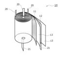
- FIG. 2 is a perspective view of the electrode body.
- the electrode body 14 shown in FIG. 2 includes an elongated positive electrode 11, an elongated negative electrode 12, and two elongated separators 13, and the positive electrode 11 and the negative electrode 12 are wound together with the separator 13 in between. It is a wound type electrode body.
- Three positive electrode leads 20 are connected to the positive electrode 11, and two negative electrode leads 21 are connected to the negative electrode 12.
- the negative electrode 12 is desirably formed to be one size larger than the positive electrode 11 and to be longer than the positive electrode 11 in the longitudinal direction and the width direction (short direction).
- the two separators 13 are formed to be at least one size larger than the positive electrode 11 and arranged so as to sandwich the positive electrode 11 therebetween.
- the electrode body 14 is not limited to the wound type, and other forms of electrode bodies may be applied, such as a laminated type electrode body in which the positive electrode 11 and the negative electrode 12 are alternately laminated with the separator 13 in between.
- the outer shape of the battery case 15 shown in FIG. 1 is cylindrical, but is not limited to this, and may be square or the like.
- the sealing body 17 includes a sealing plate 27, a current collecting plate 40, and a metal plate 41.
- the sealing body 17 has a structure in which a current collector plate 40, a metal plate 41, and a sealing plate 27 are laminated in order from the electrode body 14 side.
- the current collector plate 40 is an annular metal plate member, and has a through hole 40a in the center in the radial direction.
- the sealing plate 27 is a metal plate member without a through hole, and closes the opening of the outer can 16. The structure of the sealing plate 27 will be explained in detail later.
- the metal plate 41 is an annular metal plate member and has a through hole 41a in the center in the radial direction.
- the outer peripheral portion of the current collector plate 40 is in contact with the sealing plate 27. It is preferable that the outer peripheral portion of the current collector plate 40 is joined to the sealing plate 27 by laser welding or the like.
- the annular upper surface 45 of the current collector plate 40 has an annular recess 45a on the radially inner side of the outer circumference.
- the bottom surface 45b of the recess 45a extends in a direction substantially perpendicular to the axial direction.
- FIG. 3 is a cross-sectional view of the sealing plate before press working.
- the sealing plate 27 includes a base material 60 and a coating layer 62 formed on both sides of the base material 60. Note that the sealing plate 27 shown in FIG. 3 is press-worked to form a sealing plate 27 having a convex portion whose central portion is convex toward the outside of the battery, as shown in FIG. 1, for example. Shape.
- the base material 60 is a base material whose main component is Fe.
- the main component means the component with the highest content among the components constituting the base material 60.
- the base material 60 containing Fe as a main component it is preferable to use a stainless steel base material in terms of mechanical strength, corrosion resistance against non-aqueous electrolytes, and the like.
- the thickness of the base material 60 is not particularly limited, it is preferably, for example, 0.8 mm or more in terms of mechanical strength and the like.
- the coating layer 62 is formed on both sides of the base material 60, but it may be formed on one side. However, when forming the coating layer 62 only on one side of the base material 60, the sealing plate 27 is arranged so that the coating layer 62 formed on one side of the base material 60 is placed inside the battery. It is necessary to attach it to the outer can 16. That is, the coating layer 62 may be formed on at least one of both surfaces of the base material 60, which is the inner surface of the battery.
- the covering layer 62 is a layer containing Al and Si.
- Al and Si are present, for example, as solid solution alloys or intermetallic compounds. Due to the presence of Si in the coating layer 62, the adhesion strength to the base material 60 can be improved compared to an Al coating layer that does not contain Si. As a result, when the sealing plate 27 is pressed into a predetermined shape, the interface between the base material 60 and the coating layer 62 is prevented from cracking, and the base material 60 is prevented from being exposed from the cracked part. For example, corrosion of the base material 60 due to the non-aqueous electrolyte inside the battery is suppressed.
- the content of Si in the coating layer 62 is preferably in the range of 1% by mass to 20% by mass, for example, from 5% to 15% by mass, since it can further improve the adhesion strength with the base material 60. More preferably, it is in the range of % by mass.
- the content of Al in the coating layer 62 is, for example, preferably 80% by mass or more, and more preferably 90% by mass or more. Note that the coating layer 62 may contain impurity elements other than Si and Al.
- the content of impurity elements in the coating layer 62 is preferably, for example, 1% by mass or less.
- a compound containing Fe, Si, and Al is preferably present at the interface between the base material 60 and the coating layer 62. Thereby, the adhesion strength between the base material 60 and the coating layer 62 can be further improved.
- the compound containing Fe, Si, and Al may be present so as to cover the interface between the base material 60 and the coating layer 62, or be present in an island-like manner dispersed at the interface between the base material 60 and the coating layer 62. It's good to be doing it.
- the compound containing Fe, Si, and Al is, for example, a solid solution alloy or an intermetallic compound containing Fe, Si, and Al as main components.
- Each element constituting the coating layer 62 and each element of the compound present at the interface between the base material 60 and the coating layer 62 can be detected by analysis using, for example, an X-ray photoelectron spectrometer or an X-ray diffraction device. .
- the coating layer 62 can be formed using PVD (physical vapor deposition) such as vacuum evaporation, sputtering, or ion plating, or CVD (chemical vapor deposition) such as thermal CVD or atomic layer deposition (ALD). ), plating methods (electroplating, electroless plating, hot-dip plating, vacuum plating), etc. After forming the coating layer 62 by the above method, heat treatment may be performed as necessary. Among these, the hot-dip plating method is preferable since it is easy to form the coating layer 62.
- a compound containing Fe, Si, and Al can be formed at the interface between the base material 60 and the coating layer 62 at the same time as the coating layer 62 is formed.
- heat treatment is performed in order to form a compound containing Fe, Si, and Al at the interface between the base material 60 and the coating layer 62. This may be necessary.
- Formation of the coating layer 62 by the hot-dip plating method includes, for example, a gluing method in which the base material 60 is immersed in a hot-dip plating bath containing Al and Si and then pulled up.
- the temperature of the hot-dip plating bath is preferably in the range of 500 to 700°C, for example.
- the amount of the coating layer 62 deposited is preferably in the range of 40 to 100 g/m 2 , for example.
- the exterior can 16 shown in FIG. 1 is a cylindrical metal exterior can with a bottom and an opening.
- the outer can 16 has an annular grooved portion 35 in a portion of the cylindrical outer peripheral surface in the axial direction.
- the grooved portion 35 can be formed, for example, by spinning a part of the cylindrical outer circumferential surface radially inward and recessing it radially inward.
- the sealing plate 27 and the current collector plate 40 that constitute the sealing body 17 are arranged on the grooved part 35 and are caulked and fixed to the opening of the outer can 16 via the gasket 28, so that the internal space of the battery case 15 is sealed. Ru.
- the gasket 28 not only serves as a sealing material to maintain airtightness inside the battery, but also as an insulating material that insulates the outer can 16 and the sealing body 17.
- the external shape of the outer can 16 is not limited to a cylindrical shape with a bottom, and may be, for example, a rectangular cylindrical shape with a bottom.
- FIG. 4 is a bottom view of the sealed battery shown in FIG. 1, and is a view of the bottom of the outer can shown in FIG. 1 viewed from the outside of the sealed battery.
- the bottom of the outer can 16 is provided with a gas discharge part 30 that opens when the battery internal pressure reaches a predetermined pressure.
- a groove 31 is formed in the bottom of the outer can 16, and a portion surrounded by the groove 31 becomes the gas discharge section 30.
- the groove 31 is, for example, a stamp formed from the outer surface side of the bottom of the outer can 16, and the part of the bottom of the outer can 16 where the groove is formed is a thin part that is thinner than other parts.
- the thin wall portion ruptures and the gas discharge portion 30 opens.
- the gas discharge section 30 shown in FIG. 4 has a circular shape in plan view, the shape is not limited to this, and may be a semicircular shape, a polygonal shape, or the like.
- the positive electrode 11 includes, for example, a positive electrode current collector and positive electrode mixture layers formed on both sides of the positive electrode current collector.
- a positive electrode current collector for example, a metal foil such as aluminum or an aluminum alloy that is stable in the potential range of the positive electrode 11, a film in which the metal is disposed on the surface, or the like can be used.
- the positive electrode mixture layer includes, for example, a positive electrode active material, a conductive agent, and a binder.
- the positive electrode 11 is made by applying a positive electrode mixture slurry containing a positive electrode active material, a conductive agent, a binder, etc. onto a positive electrode current collector, drying the coating film, and then compressing the positive electrode mixture layer to form a positive electrode mixture layer. It can be produced by forming on both sides of a current collector.
- the positive electrode active material is, for example, a lithium-containing metal composite oxide that can reversibly insert and extract lithium.
- Metal elements contained in the lithium-containing metal composite oxide include Ni, Co, Mn, Al, B, Mg, Ti, V, Cr, Fe, Cu, Zn, Ga, Sr, Zr, Nb, In, and Sn. , Ta, W, etc.
- An example of a preferable lithium-containing metal composite oxide is a composite oxide containing at least one of Ni, Co, Mn, and Al.
- Examples of the conductive agent contained in the positive electrode mixture layer include carbon materials such as carbon black, acetylene black, Ketjen black, and graphite. Binders included in the positive electrode mixture layer include polytetrafluoroethylene (PTFE), fluororesins such as polyvinylidene fluoride (PVdF), polyacrylonitrile (PAN), polyimide resins, acrylic resins, polyolefin resins, and styrene-butadiene. Examples include rubber (SBR) or modified products thereof, cellulose derivatives such as carboxymethylcellulose (CMC) or its salts, polyacrylic acid (PAA) or its salts, polyvinyl alcohol, and polyethylene oxide (PEO).
- PTFE polytetrafluoroethylene
- PVdF polyvinylidene fluoride
- PAN polyacrylonitrile
- SBR rubber
- cellulose derivatives such as carboxymethylcellulose (CMC) or its salts
- PAA polyacrylic acid
- the negative electrode 12 includes, for example, a negative electrode current collector and negative electrode mixture layers formed on both sides of the negative electrode current collector.
- a negative electrode current collector for example, a metal foil such as copper or copper alloy that is stable in the potential range of the negative electrode 12, a film having the metal disposed on the surface layer, or the like can be used.
- the negative electrode mixture layer includes, for example, a negative electrode active material and a binder.
- the negative electrode 12 is made by applying a negative electrode mixture slurry containing a negative electrode active material, a binder, etc. onto a negative electrode current collector, drying the coating film, and then compressing the negative electrode mixture layer to form a negative electrode mixture layer on the current collector. It can be produced by forming on both sides.
- the negative electrode active material is one that can reversibly absorb and release lithium ions, and includes carbon materials, metals that alloy with lithium such as silicon (Si) and tin (Sn), alloys containing the metal, Examples include compounds containing metals.
- the carbon material for example, graphite such as natural graphite such as flaky graphite, lumpy graphite, and earthy graphite, artificial graphite such as lumpy artificial graphite, and graphitized mesophase carbon microbeads is preferable.
- the binder contained in the negative electrode mixture layer is a fluororesin, PAN, polyimide resin, acrylic resin, polyolefin resin, SBR or a modified product thereof, cellulose derivative such as CMC or a salt thereof, PAA. Or a salt thereof, polyvinyl alcohol, PEO, etc. may be used.
- a porous sheet having ion permeability and insulation properties is used for the separator 13.
- porous sheets include microporous thin films, woven fabrics, and nonwoven fabrics.
- Preferable materials for the separator 13 include polyolefin resins such as polyethylene and polypropylene, cellulose, and the like.
- the separator 13 may have either a single layer structure or a laminated structure. A heat-resistant layer or the like may be formed on the surface of the separator 13.
- the positive electrode lead 20 attached to the positive electrode 11 extends to the sealing body 17 side through the through hole of the insulating plate 18, and passes through the through hole 40a of the current collecting plate 40 to the current collecting plate. 40 along the bottom surface 45b of the recess 45a.
- the tip of the positive electrode lead 20 is sandwiched between the bottom surface 45b of the recess 45a of the current collector plate 40 and the lower surface 47 of the metal plate 41.
- the positive electrode lead 20 is joined to the bottom surface 45b of the recess 45a of the current collector plate 40. Further, the current collector plate 40 and the metal plate 41 are also bonded, and the positive electrode lead 20 and the metal plate 41 are also bonded.
- connections can be made, for example, by laser welding from the side opposite to the current collector plate 40 side in the thickness direction of the metal plate 41 with the tip of the positive electrode lead 20 sandwiched between the current collector plate 40 and the metal plate 41. This can be achieved with Note that the current collector plate 40 does not need to be joined to the metal plate 41, and the positive electrode lead 20 does not need to be joined to the metal plate 41.
- the first negative electrode lead 21a joined to the end of the negative electrode 12 on the winding start side passes through the through hole 19a of the insulating plate 19 and is bent toward the hollow part 14a of the electrode body 14.
- the second negative electrode lead 21b joined to the end of the negative electrode 12 on the winding end side passes through the outside of the insulating plate 19 and is bent so as to overlap the first negative electrode lead 21a.
- the overlapping portion of the first negative electrode lead 21a and the second negative electrode lead 21b is joined to the inner surface of the bottom portion 68 of the outer can 16 by resistance welding using a welding rod inserted into the hollow portion 14a of the electrode body 14.
- the sealing plate 27 electrically connected to the positive electrode lead 20 serves as a positive terminal
- the outer can 16 electrically connected to the negative electrode lead 21 serves as a negative terminal
- the non-aqueous electrolyte includes a non-aqueous solvent and an electrolyte salt dissolved in the non-aqueous solvent.
- the non-aqueous solvent for example, esters, ethers, nitriles, amides, and mixed solvents of two or more of these may be used.
- the non-aqueous solvent may contain a halogen-substituted product in which at least a portion of the hydrogen atoms of these solvents are replaced with halogen atoms such as fluorine.
- the non-aqueous electrolyte is not limited to a liquid electrolyte, and may be a solid electrolyte using a gel-like polymer or the like.
- a lithium salt such as LiPF 6 is used as the electrolyte salt.
- a base material made of stainless steel (17% by mass of chromium) is immersed in a hot-dip plating bath containing Al and Si, then pulled out and rapidly cooled to form a coating layer containing Al and Si on both sides of the base material.
- a formed plate member was produced.
- the coating weight of the coating layer was 40 g/m 2 .
- the obtained plate member was press-worked to produce a sealing plate having a convex portion in the center as shown in FIG.
- a sealing plate having a convex portion in the center as shown in FIG.
Landscapes
- Chemical & Material Sciences (AREA)
- Chemical Kinetics & Catalysis (AREA)
- Electrochemistry (AREA)
- General Chemical & Material Sciences (AREA)
- Inorganic Chemistry (AREA)
- Sealing Battery Cases Or Jackets (AREA)
Priority Applications (3)
| Application Number | Priority Date | Filing Date | Title |
|---|---|---|---|
| CN202380026421.9A CN118872128A (zh) | 2022-03-18 | 2023-03-06 | 密闭型电池 |
| US18/845,320 US20250192291A1 (en) | 2022-03-18 | 2023-03-06 | Hermetically sealed battery |
| JP2024507758A JPWO2023176547A1 (https=) | 2022-03-18 | 2023-03-06 |
Applications Claiming Priority (2)
| Application Number | Priority Date | Filing Date | Title |
|---|---|---|---|
| JP2022-044503 | 2022-03-18 | ||
| JP2022044503 | 2022-03-18 |
Publications (1)
| Publication Number | Publication Date |
|---|---|
| WO2023176547A1 true WO2023176547A1 (ja) | 2023-09-21 |
Family
ID=88023046
Family Applications (1)
| Application Number | Title | Priority Date | Filing Date |
|---|---|---|---|
| PCT/JP2023/008311 Ceased WO2023176547A1 (ja) | 2022-03-18 | 2023-03-06 | 密閉型電池 |
Country Status (4)
| Country | Link |
|---|---|
| US (1) | US20250192291A1 (https=) |
| JP (1) | JPWO2023176547A1 (https=) |
| CN (1) | CN118872128A (https=) |
| WO (1) | WO2023176547A1 (https=) |
Citations (5)
| Publication number | Priority date | Publication date | Assignee | Title |
|---|---|---|---|---|
| JPH0256849A (ja) * | 1988-08-23 | 1990-02-26 | Matsushita Electric Ind Co Ltd | 有機電解液電池 |
| JP2000149884A (ja) * | 1998-11-02 | 2000-05-30 | Japan Storage Battery Co Ltd | 非水電解質電池 |
| JP2009245719A (ja) * | 2008-03-31 | 2009-10-22 | Nisshin Steel Co Ltd | 電池ケース用改質Al系めっき鋼材並びに電池ケースおよびリチウムイオン二次電池 |
| JP2017126407A (ja) * | 2016-01-12 | 2017-07-20 | トヨタ自動車株式会社 | 二次電池 |
| JP2018014160A (ja) * | 2014-11-27 | 2018-01-25 | 三洋電機株式会社 | 円筒形非水電解質二次電池 |
-
2023
- 2023-03-06 JP JP2024507758A patent/JPWO2023176547A1/ja active Pending
- 2023-03-06 CN CN202380026421.9A patent/CN118872128A/zh active Pending
- 2023-03-06 US US18/845,320 patent/US20250192291A1/en active Pending
- 2023-03-06 WO PCT/JP2023/008311 patent/WO2023176547A1/ja not_active Ceased
Patent Citations (5)
| Publication number | Priority date | Publication date | Assignee | Title |
|---|---|---|---|---|
| JPH0256849A (ja) * | 1988-08-23 | 1990-02-26 | Matsushita Electric Ind Co Ltd | 有機電解液電池 |
| JP2000149884A (ja) * | 1998-11-02 | 2000-05-30 | Japan Storage Battery Co Ltd | 非水電解質電池 |
| JP2009245719A (ja) * | 2008-03-31 | 2009-10-22 | Nisshin Steel Co Ltd | 電池ケース用改質Al系めっき鋼材並びに電池ケースおよびリチウムイオン二次電池 |
| JP2018014160A (ja) * | 2014-11-27 | 2018-01-25 | 三洋電機株式会社 | 円筒形非水電解質二次電池 |
| JP2017126407A (ja) * | 2016-01-12 | 2017-07-20 | トヨタ自動車株式会社 | 二次電池 |
Also Published As
| Publication number | Publication date |
|---|---|
| US20250192291A1 (en) | 2025-06-12 |
| CN118872128A (zh) | 2024-10-29 |
| JPWO2023176547A1 (https=) | 2023-09-21 |
Similar Documents
| Publication | Publication Date | Title |
|---|---|---|
| JP7799470B2 (ja) | 円筒形電池、及び円筒形電池の製造方法 | |
| JP7709293B2 (ja) | 円筒形電池 | |
| WO2023085030A1 (ja) | 円筒形電池 | |
| WO2023145674A1 (ja) | 円筒形の非水電解質二次電池 | |
| WO2023145679A1 (ja) | 非水電解質二次電池 | |
| CN112204767B (zh) | 非水电解质二次电池 | |
| WO2022202395A1 (ja) | 円筒形電池 | |
| JP7738641B2 (ja) | 円筒形電池 | |
| WO2023054005A1 (ja) | 円筒形電池 | |
| WO2023281973A1 (ja) | 円筒形電池 | |
| WO2023176547A1 (ja) | 密閉型電池 | |
| JP7793532B2 (ja) | 円筒形電池 | |
| WO2023189790A1 (ja) | 円筒形電池 | |
| EP4270613A1 (en) | Hermetically sealed battery | |
| WO2023162961A1 (ja) | 二次電池用負極及び二次電池 | |
| EP4583298A1 (en) | Cylindrical battery | |
| JP7301267B2 (ja) | 非水電解質二次電池 | |
| EP4583299A1 (en) | Cylindrical battery | |
| JP7818534B2 (ja) | 円筒形電池 | |
| EP4475297A1 (en) | Power storage device | |
| WO2023162710A1 (ja) | 円筒形の非水電解質二次電池 | |
| WO2023223791A1 (ja) | 円筒形電池 | |
| WO2024070513A1 (ja) | 円筒形電池 | |
| WO2024161982A1 (ja) | 円筒形の非水電解質二次電池 | |
| WO2025204681A1 (ja) | 円筒形電池 |
Legal Events
| Date | Code | Title | Description |
|---|---|---|---|
| 121 | Ep: the epo has been informed by wipo that ep was designated in this application |
Ref document number: 23770503 Country of ref document: EP Kind code of ref document: A1 |
|
| WWE | Wipo information: entry into national phase |
Ref document number: 2024507758 Country of ref document: JP |
|
| WWE | Wipo information: entry into national phase |
Ref document number: 18845320 Country of ref document: US Ref document number: 202380026421.9 Country of ref document: CN |
|
| NENP | Non-entry into the national phase |
Ref country code: DE |
|
| 122 | Ep: pct application non-entry in european phase |
Ref document number: 23770503 Country of ref document: EP Kind code of ref document: A1 |
|
| WWP | Wipo information: published in national office |
Ref document number: 18845320 Country of ref document: US |