WO2023175943A1 - 異物検査装置 - Google Patents
異物検査装置 Download PDFInfo
- Publication number
- WO2023175943A1 WO2023175943A1 PCT/JP2022/012744 JP2022012744W WO2023175943A1 WO 2023175943 A1 WO2023175943 A1 WO 2023175943A1 JP 2022012744 W JP2022012744 W JP 2022012744W WO 2023175943 A1 WO2023175943 A1 WO 2023175943A1
- Authority
- WO
- WIPO (PCT)
- Prior art keywords
- container
- foreign
- foreign matter
- display device
- liquid
- Prior art date
- Legal status (The legal status is an assumption and is not a legal conclusion. Google has not performed a legal analysis and makes no representation as to the accuracy of the status listed.)
- Ceased
Links
Images


Classifications
-
- G—PHYSICS
- G01—MEASURING; TESTING
- G01N—INVESTIGATING OR ANALYSING MATERIALS BY DETERMINING THEIR CHEMICAL OR PHYSICAL PROPERTIES
- G01N21/00—Investigating or analysing materials by the use of optical means, i.e. using sub-millimetre waves, infrared, visible or ultraviolet light
- G01N21/84—Systems specially adapted for particular applications
- G01N21/88—Investigating the presence of flaws or contamination
- G01N21/90—Investigating the presence of flaws or contamination in a container or its contents
- G01N21/9018—Dirt detection in containers
- G01N21/9027—Dirt detection in containers in containers after filling
-
- G—PHYSICS
- G06—COMPUTING OR CALCULATING; COUNTING
- G06T—IMAGE DATA PROCESSING OR GENERATION, IN GENERAL
- G06T7/00—Image analysis
- G06T7/0002—Inspection of images, e.g. flaw detection
- G06T7/0004—Industrial image inspection
- G06T7/0008—Industrial image inspection checking presence/absence
-
- G—PHYSICS
- G01—MEASURING; TESTING
- G01N—INVESTIGATING OR ANALYSING MATERIALS BY DETERMINING THEIR CHEMICAL OR PHYSICAL PROPERTIES
- G01N21/00—Investigating or analysing materials by the use of optical means, i.e. using sub-millimetre waves, infrared, visible or ultraviolet light
- G01N21/84—Systems specially adapted for particular applications
- G01N21/88—Investigating the presence of flaws or contamination
- G01N21/8851—Scan or image signal processing specially adapted therefor, e.g. for scan signal adjustment, for detecting different kinds of defects, for compensating for structures, markings, edges
-
- G—PHYSICS
- G06—COMPUTING OR CALCULATING; COUNTING
- G06T—IMAGE DATA PROCESSING OR GENERATION, IN GENERAL
- G06T7/00—Image analysis
- G06T7/0002—Inspection of images, e.g. flaw detection
- G06T7/0004—Industrial image inspection
-
- G—PHYSICS
- G06—COMPUTING OR CALCULATING; COUNTING
- G06V—IMAGE OR VIDEO RECOGNITION OR UNDERSTANDING
- G06V10/00—Arrangements for image or video recognition or understanding
- G06V10/70—Arrangements for image or video recognition or understanding using pattern recognition or machine learning
- G06V10/764—Arrangements for image or video recognition or understanding using pattern recognition or machine learning using classification, e.g. of video objects
-
- G—PHYSICS
- G06—COMPUTING OR CALCULATING; COUNTING
- G06V—IMAGE OR VIDEO RECOGNITION OR UNDERSTANDING
- G06V10/00—Arrangements for image or video recognition or understanding
- G06V10/70—Arrangements for image or video recognition or understanding using pattern recognition or machine learning
- G06V10/82—Arrangements for image or video recognition or understanding using pattern recognition or machine learning using neural networks
-
- G—PHYSICS
- G06—COMPUTING OR CALCULATING; COUNTING
- G06T—IMAGE DATA PROCESSING OR GENERATION, IN GENERAL
- G06T2207/00—Indexing scheme for image analysis or image enhancement
- G06T2207/10—Image acquisition modality
- G06T2207/10016—Video; Image sequence
-
- G—PHYSICS
- G06—COMPUTING OR CALCULATING; COUNTING
- G06T—IMAGE DATA PROCESSING OR GENERATION, IN GENERAL
- G06T2207/00—Indexing scheme for image analysis or image enhancement
- G06T2207/20—Special algorithmic details
- G06T2207/20081—Training; Learning
-
- G—PHYSICS
- G06—COMPUTING OR CALCULATING; COUNTING
- G06T—IMAGE DATA PROCESSING OR GENERATION, IN GENERAL
- G06T2207/00—Indexing scheme for image analysis or image enhancement
- G06T2207/20—Special algorithmic details
- G06T2207/20084—Artificial neural networks [ANN]
-
- G—PHYSICS
- G06—COMPUTING OR CALCULATING; COUNTING
- G06T—IMAGE DATA PROCESSING OR GENERATION, IN GENERAL
- G06T2207/00—Indexing scheme for image analysis or image enhancement
- G06T2207/30—Subject of image; Context of image processing
- G06T2207/30004—Biomedical image processing
Definitions
- the present invention relates to a foreign matter inspection device, a foreign matter inspection method, and a recording medium.
- a device has been proposed that inspects the presence or absence of foreign matter in a liquid sealed in a container.
- the moving trajectory of floating objects is calculated from a plurality of images obtained by continuously photographing liquid in a container with a camera, and based on the characteristics of the moving trajectory, floating objects are determined to be air bubbles or foreign objects.
- the determination result is displayed on the screen of the display device.
- An object of the present invention is to provide a foreign matter inspection device that solves the above-mentioned problems.
- a foreign matter inspection device includes: a detection means for detecting foreign substances present in the liquid and their types from a plurality of images obtained by sequentially photographing a container filled with the liquid; a display control means for outputting the type of the detected foreign object to a display device; It is configured to include.
- a foreign substance inspection method includes: Detecting foreign objects present in the liquid and their types from a plurality of images obtained by sequentially photographing a container containing the liquid, outputting the type of the detected foreign object to a display device; It is configured as follows.
- a computer-readable recording medium includes: to the computer, A process of detecting foreign substances present in the liquid and their types from a plurality of images obtained by sequentially photographing a container containing the liquid; a process of outputting the type of the detected foreign object to a display device;
- the computer is configured to record a program that performs the following.
- the present invention outputs the type of detected foreign object to the display device, so that the type of foreign object can be recognized.
- FIG. 1 is a block diagram of an inspection system according to a first embodiment of the present invention. It is a block diagram showing an example of an inspection device in a 1st embodiment of the present invention.
- FIG. 3 is a diagram illustrating a configuration example of image information in the first embodiment of the present invention.
- FIG. 3 is a diagram illustrating a configuration example of tracking information in the first embodiment of the present invention. It is a figure showing an example of composition of test result information in a 1st embodiment of the present invention.
- FIG. 3 is a schematic diagram showing an example of a moving trajectory still image that visualizes moving trajectory information of a foreign object in the first embodiment of the present invention.
- FIG. 3 is a diagram showing an example of the configuration of foreign matter contamination factor information in the first embodiment of the present invention.
- FIG. 2 is a block diagram of a foreign matter inspection device according to a second embodiment of the present invention.
- FIG. 1 is a block diagram of an inspection system 100 according to a first embodiment of the present invention.
- an inspection system 100 is a system that inspects the presence or absence of foreign substances in a liquid sealed in a container 400.
- the inspection system 100 includes a gripping device 110, a lighting device 120, a camera device 130, an inspection device 200, and a display device 300 as main components.
- the container 400 is a transparent or translucent container such as a glass bottle or a plastic bottle.
- the inside of the container 400 is sealed and filled with a liquid such as a medicine or water. Further, there is a possibility that foreign matter is mixed into the liquid sealed in the container 400. Examples of foreign objects include glass pieces, plastic pieces, rubber pieces, hair pieces/fiber pieces, metal pieces, and the like.
- the gripping device 110 is configured to grip the container 400 in a predetermined posture.
- the predetermined posture is arbitrary.
- the predetermined posture may be the posture when the container 400 is upright.
- the predetermined posture may be a posture in which the container 400 is tilted at a predetermined angle from an upright posture.
- a posture in which the container 400 stands upright will be described as a predetermined posture.
- Any mechanism can be used to hold the container 400 in an upright position.
- the gripping mechanism includes a pedestal on which the container 400 is placed in an upright position, and a member that presses the top surface of the rubber stopper 401, which is the top of the container 400 placed on the pedestal. It's good that it has been done.
- the gripping device 110 is configured to rotate, tilt, or swing the container 400 in a predetermined direction from an upright position while gripping the container 400.
- the mechanism for rotating, tilting, and rocking the container 400 is arbitrary.
- the mechanism for rotating, tilting, and swinging may include a motor that rotates, tilting, and swinging the entire gripping mechanism while holding the container 400.
- the gripping device 110 is connected to the inspection device 200 by wire or wirelessly.
- the gripping device 110 rotates, tilts, and swings the container 400 in a predetermined direction from an upright posture while gripping the container 400.
- the gripping device 110 stops the operations of rotating, tilting, and rocking the container 400, and returns to the state of gripping the container 400 in an upright posture.
- the illumination device 120 is configured to irradiate the liquid sealed in the container 400 with illumination light.
- the lighting device 120 is, for example, a surface light source whose size corresponds to the size of the container 400.
- the lighting device 120 is installed on the opposite side of the container 400 from the side where the camera device 130 is installed. That is, the illumination by the illumination device 120 is transmitted illumination.
- the position of the illumination device 120 is not limited to this, and the illumination device 120 may be installed, for example, on the bottom side of the container 400 or in a position adjacent to the camera device 130 to take a picture using reflected light illumination.
- the camera device 130 is a high-speed photographing device that continuously photographs the liquid inside the container 400 at a predetermined high frame rate from a predetermined position on the opposite side of the container 400 to the side where the illumination device 120 is installed.
- the camera device 130 may include, for example, a color camera or a monochrome camera equipped with a CCD (Charge-Coupled Device) image sensor or a CMOS (Complementary MOS) image sensor having a pixel capacity of several million pixels.
- the camera device 130 is connected to the inspection device 200 by wire or wirelessly.
- the camera device 130 is configured to transmit time-series images obtained by photographing to the inspection device 200 together with information indicating the time of photographing.
- the display device 300 is a display device such as an LCD (Liquid Crystal Display).
- the display device 300 is connected to the inspection device 200 by wire or wirelessly.
- the display device 300 is configured to display the results of an inspection of the container 400 performed by the inspection device 200 and the like.
- the inspection device 200 is an information processing device that performs image processing on time-series images taken by the camera device 130 to inspect the presence or absence of foreign objects in the liquid sealed in the container 400 and the type of foreign objects. It is.
- the inspection device 200 is connected to the gripping device 110, the camera device 130, and the display device 300 by wire or wirelessly.
- FIG. 2 is a block diagram showing an example of the inspection device 200.
- the inspection device 200 includes a communication I/F section 210, an operation input section 220, a storage section 230, and an arithmetic processing section 240.
- the communication I/F section 210 is composed of a data communication circuit, and is configured to perform data communication with the gripping device 110, the camera device 130, the display device 300, and other external devices (not shown) by wire or wirelessly.
- the operation input unit 220 includes an operation input device such as a keyboard and a mouse, and is configured to detect an operator's operation and output it to the arithmetic processing unit 240.
- the storage unit 230 is composed of one or more types of storage devices such as a hard disk or memory, and is configured to store processing information and programs 231 necessary for various processes in the arithmetic processing unit 240.
- the program 231 is a program that implements various processing units by being read and executed by the arithmetic processing unit 240.
- the information is read in advance and stored in the storage unit 230.
- the main processing information stored in the storage unit 230 includes image information 232, tracking information 233, test result information 234, and foreign matter contamination factor information 236.
- the image information 232 includes time-series images obtained by continuously photographing the liquid in the container 400 using the camera device 130. If floating objects are present in the liquid in the container 400, the image information 232 includes an image of the floating objects.
- FIG. 3 shows a configuration example of the image information 232.
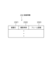
- the image information 232 in this example is composed of entries consisting of a set of a container ID 2321, a photographing time 2322, and a frame image 2323.
- An ID that uniquely identifies the container 400 is set in the container ID 2321 item.
- Possible examples of the container ID 2321 include a serial number assigned to the container 400, a bar code affixed to the container 400, and object fingerprint information collected from the rubber stopper 401 of the container 400.
- the photographing time and frame image are set in each item of photographing time 2322 and frame image 2323.
- the photographing time 2322 is set to an accuracy (for example, in milliseconds) that allows the frame image to be distinguished from other frame images of the same container ID.
- the photographing time 2322 for example, the elapsed time from the time when the rotation, tilting, and rocking of the container 400 is stopped may be used.
- the container ID 2321 is associated with each frame image 2323, but the container ID 2321 may be associated with each group of a plurality of frame images 2323.
- the tracking information 233 includes time-series data representing the movement locus of the floating object that is tracked by detecting an image of the floating object present in the liquid in the container 400.
- FIG. 4 shows an example of the configuration of the tracking information 233.
- the tracking information 233 in this example is composed of entries of a container ID 2331, a set of a tracking ID 2332, and a pointer 2333.
- An ID that uniquely identifies the container 400 is set in the container ID 2331 entry.
- An entry consisting of a pair of tracking ID 2332 and pointer 2333 is provided for each floating object to be tracked.
- an ID for identifying the floating object to be tracked from other floating objects in the same container 400 is set.
- a pointer to movement trajectory information 2334 of the floating object to be tracked is set.
- the movement trajectory information 2334 is composed of entries consisting of a set of time 23341, position information 23342, size 23343, brightness distribution 23344, and shape 23345.
- the time 23341, position information 23342, size 23343, brightness distribution 23344, and shape 23345 items include the shooting time, coordinate values indicating the position of the floating object to be tracked at the shooting time, the size of the floating object, and the inside of the floating object area.
- the brightness distribution and the shape of the floating object are set.
- the photographing time 2322 of the frame image is used as the photographing time set to the time 23341.
- the coordinate values may be, for example, coordinate values in a predetermined coordinate system.
- the predetermined coordinate system may be a camera coordinate system centered on the camera, or a world coordinate system centered on a certain position in real space.
- Entries of movement trajectory information 2334 are arranged in order of time 23341.
- the time 23341 of the first entry is the tracking start time.
- the time 23341 of the last entry is the tracking end time.
- the times 23341 of entries other than the first and last entries are tracking intermediate times.
- the test result information 234 includes information according to the test results of the container 400.
- FIG. 5 shows a configuration example of the test result information 234.
- the inspection result information 234 in this example is based on the following entries: container ID 2341, inspection result 2342, number of detected foreign objects 2343, number of bubbles detected 2344, set of detected foreign object ID 2345 and pointer 2346, and set of detected air bubble ID 2347 and pointer 2348. It is configured.
- An ID that uniquely identifies the container 400 to be inspected is set in the container ID 2341 entry.
- an OK inspection pass
- NG inspection failure
- the total number of detected foreign objects and/or the total number of foreign objects for each type are set.
- the total number of detected bubbles is set in the entry 2344 for the number of detected bubbles.
- An entry consisting of a detected foreign object ID 2345 and a pointer 2346 is provided for each detected foreign object.
- an ID for distinguishing the detected foreign object from other foreign objects in the same container 400 is set.
- a pointer to detected foreign object information 2349 of the detected foreign object is set.
- An entry for a pair of detected bubble ID 2347 and pointer 2348 is provided for each detected bubble.
- an ID for distinguishing the detected bubble from other bubbles in the same container 400 is set.
- a pointer to detected bubble information 2350 of the detected bubble is set.
- the detected foreign object information 2349 is composed of the following entries: a pair of a tracking ID 23491 and a pointer 23492, a foreign object type 23493, a movement trajectory still image 23494, and a movement trajectory video 23495.
- the tracking ID 2332 of the detected foreign object is set in the tracking ID 23491 item.
- a pointer to the movement trajectory information 2334 of the detected foreign object is set.
- the determined foreign material type is set in the foreign material type 23493 entry.
- the probability of the determination result may be further set in the foreign object type entry 23493.
- the probability of a determination result is an index representing the certainty of the determination result.
- FIG. 6 is a schematic diagram showing an example of a moving trajectory still image 23494.
- the moving trajectory still image 23494 in this example is a composite image in which the background image 234941 and the moving trajectory image 234942 are superimposed.
- the background image 234941 for example, the most reliable frame image in which the detected foreign object is determined to be a specific type of foreign object rather than a bubble may be used.
- the background image 234941 may be a frame image other than the above, for example, any frame image in which a detected foreign object is captured.
- the movement trajectory image 234942 includes lines representing the movement trajectory of the foreign object. In the example of FIG. 6, broken lines are used, but solid lines may also be used. Further, the moving trajectory image 234942 has an arrow added thereto indicating the moving direction of the foreign object. However, the form representing the moving direction of the foreign object is not limited to the arrow.
- the method of moving the foreign object may be expressed by changing the line type, width, color, etc. of the line representing the movement trajectory of the foreign object as time passes.
- the display form of the moving trajectory image 234942 may be changed depending on the moving speed of the foreign object. For example, the moving speed of the foreign object may be expressed by changing the line type, width, color, etc. of the line depending on the moving speed of the foreign object.
- a display column 234943 that displays the type of foreign object is drawn in the moving trajectory still image 23494.
- the type of foreign object set in the foreign object type 23493 is displayed, for example, in text.
- an index 234944 is drawn on the moving trajectory still image 23494 to indicate a location that serves as a basis for determining a foreign object.
- the index 234944 is a rectangle surrounding the location that is the basis for determination, but is not limited thereto.
- the location serving as the basis for determining a foreign object means a location in the movement trajectory information where it is determined that the foreign object is not a bubble but a specific type of foreign object.
- a metal piece such as a stainless steel piece has a high specific gravity, it is less affected by the movement of the liquid, and a falling trajectory can be obtained in a substantially straight line. Therefore, the location where the object is falling in a straight line becomes the location that is the basis for determining that it is a metal piece. Furthermore, in the case of a foreign object such as a piece of rubber having a specific gravity smaller than that of a metal piece, a place where the foreign object has settled down to a lower position than the position at the tracking start time can be a place that becomes the basis for determination.
- the detected bubble information 2350 is composed of entries of a pair of tracking ID 23501 and pointer 23502, determination result 23503, movement trajectory still image 23504, and movement trajectory video 23505.
- the tracking ID 2332 of the detected bubble is set in the tracking ID 23501 item.
- a pointer to movement trajectory information 2334 of the detected bubble is set in the item 23502 of pointer.
- text indicating that the determination result is "bubbles" is set.
- a probability of the judgment result may be further set.
- At least one still image that visualizes the movement trajectory information 2334 of the detected bubble is set in the movement trajectory still image 23504 entry.
- a moving image that visualizes the moving trajectory information 2334 of the detected bubble is set.
- the foreign matter contamination factor information 236 includes information regarding the cause of foreign matter contamination in the container 400.
- FIG. 7 shows an example of the foreign matter contamination factor information 236.
- the foreign matter contamination factor information 236 is composed of a plurality of entries 2361, and each entry 2361 is composed of a pair of a foreign matter type 23611 and a factor 23612.
- hair pieces/fiber pieces, plastic pieces, rubber pieces, glass pieces, and metal pieces are set in the foreign object type 23611 item.
- Factor 23612 also includes, for example, "person” for hair/fiber pieces, "container” for plastic and glass pieces, “container stopper” for rubber pieces, and metal pieces.
- "Manufacturing equipment” is set respectively. This means, for example, that the metal piece is a foreign object originating from manufacturing equipment.
- the arithmetic processing unit 240 has a microprocessor such as an MPU and its peripheral circuits, and by reading and executing a program 231 from the storage unit 230, the above hardware and the program 231 cooperate to realize various processing units. is configured to do so.
- the main processing units realized by the arithmetic processing unit 240 include an acquisition unit 241, a detection unit 242, and a display control unit 243.
- the acquisition unit 241 is configured to control the gripping device 110 and the camera device 130 to acquire image information 232 depicting an image of floating objects present in the liquid sealed in the container 400. Further, the acquisition unit 241 is configured to acquire tracking information 233 including time-series data representing the movement trajectory of the floating object by analyzing the image information 232.
- the detection unit 242 is configured to detect whether or not a foreign object is present in the liquid in the container 400 based on the tracking information 233 acquired by the acquisition unit 241, and further to detect the type of foreign object present. . Furthermore, the detection unit 242 is configured to create test result information 234 based on the detection results and store it in the storage unit 230.
- the display control unit 243 is configured to output the test result information 234 to the display device 300 as soon as possible after the test result information 234 is created by the detection unit 242.
- FIG. 8 is a flowchart showing an example of the operation of the inspection system 100 from the start of inspection to the end of inspection for one container 400.
- the acquisition unit 241 induces the flow of liquid within the container 400 (step S1).
- the acquisition unit 241 rotates, tilts, and swings the container 400 using the gripping device 110, and then holds the container 400 still in an upright posture.
- the acquisition unit 241 continuously images the liquid in the container 400 with the camera device 130 under transmitted illumination by the illumination device 120, thereby capturing images over a predetermined length of time at a predetermined frame rate.
- a time series of images is acquired (step S2).
- the time-series images acquired from the camera device 130 by the acquisition unit 241 are stored in the storage unit 230 as image information 232.
- the image information 232 includes an entry consisting of a set of a container ID 2321, a photographing time 2322, and a frame image 2323.
- the detection unit 242 detects floating objects present in the liquid in the time-series images included in the image information 232 (step S3).
- the detection unit 242 tracks the detected floating object in the time-series images included in the image information 232 (step S4).
- the detection unit 242 stores the tracking results of each of the tracked floating objects in the storage unit 230 as tracking information 233.
- the tracking information 233 includes movement trajectory information 2334 for each floating object to be tracked. Further, a plurality of entries of movement trajectory information 2334 are arranged in order of time 23341, and each entry has position information 23342, size 23343, brightness distribution 23344, and shape 23345 of the floating object to be tracked.
- the detection unit 242 determines whether the floating object is a foreign object or a bubble based on the movement trajectory information 2334 of the floating object. Furthermore, the type of floating matter that is a foreign matter is determined (step S5). Next, the detection unit 242 creates inspection result information 234 recording the determination results for each floating object, and stores it in the storage unit 230 (step S6). As illustrated in FIG. 5, the inspection result information 234 includes a container ID 2341, an inspection result 2342, the number of detected foreign objects 2343, the number of bubbles detected 2344, detected foreign object information 2349 for each detected foreign object, and detected air bubbles for each detected air bubble. Contains information 2350.
- the detected foreign object information 2349 includes a foreign object type 23493, a moving trajectory still image 23494, a moving trajectory moving image 23495, and the like.
- the detected bubble information 2350 includes a determination result (bubble) 23503, a movement trajectory still image 23504, a movement trajectory video 23505, and the like.
- the display control unit 243 outputs the test result information 234 of the container 400 to the display device 300 (step S7).
- the acquisition unit 241 first rotates, tilts, and swings the container 400 to be inspected by activating the gripping device 110 that grips the container 400 in an upright posture. Next, after a certain period of time has passed after activation, the acquisition unit 241 stops the gripping device 110 to keep the container 400 still in a predetermined posture. In this way, by tilting, rocking, and rotating the container 400 for a certain period of time and then letting it stand still, a state is obtained in which the liquid flows due to inertia within the stationary container 400. Next, the acquisition unit 241 starts an operation of continuously photographing the liquid in the container 400 at a predetermined frame rate with the camera device 130 under transmitted illumination by the illumination device 120. That is, assuming that time Ts is the time when the container 400 comes to rest after being rotated, tilted, and swung, the acquisition unit 241 starts the above-mentioned photographing operation from time Ts.
- the acquisition unit 241 continues to continuously photograph the liquid in the container 400 with the camera device 130 from time Ts until time Te at which a predetermined time Tw has elapsed.
- the predetermined time Tw is set such that, for example, if it is assumed that all floating objects floating in the liquid are bubbles, all the bubbles move upwards in the container 400 and are no longer expected to move downwards.
- the length of time may be set to be longer than the time required to obtain a suitable movement trajectory (hereinafter referred to as the minimum imaging time length).
- the minimum imaging time length may be determined in advance through experiments or the like, and may be fixedly set in the acquisition unit 241. Note that, when the time Te is reached, the acquisition unit 241 may immediately stop photographing by the camera device 130, or may continue photographing by the camera device 130.
- the acquisition unit 241 adds a photographing time and a container ID to each of the time-series frame images acquired from the camera device 130, and stores them as image information 232 in the storage unit 230.
- the acquisition unit 241 detects the shadow of the floating object in the liquid in the container 400 from each of these frame images. For example, the acquisition unit 241 detects the shadow of floating objects in the liquid by a method described below. However, the acquisition unit 241 may detect the shadow of floating objects in the liquid using methods other than those described below.
- the acquisition unit 241 performs binarization processing on each frame image to create a binarized frame image.
- the acquisition unit 241 detects the shadow of floating objects from each of the binarized frame images in the following manner.
- the acquisition unit 241 sets the binarized frame image from which the shadow of the floating object is to be detected as the binarized frame image of interest.
- a difference image between the binarized frame image of interest and a binarized frame image whose photographing time is after ⁇ t is generated.
- ⁇ t is set to a time such that the same floating objects partially overlap in the two images, or even if they do not overlap, they appear at very close positions. Therefore, the time difference ⁇ t is determined depending on the properties of the liquid and foreign matter, the flow state, and the like.
- the matching image portions of the two binarized frame images are erased, and only the different image portions are left.
- the acquisition unit 241 detects a shadow in the binarized frame image of interest corresponding to a location where a shadow appears in the difference image as a shadow of a floating object present in the binarized frame image of interest.
- the acquisition unit 241 tracks the detected floating objects in the time-series images, and creates tracking information 233 according to the tracking results.
- the acquisition unit 241 initializes the tracking information 233.
- the container ID of container 400 is set in the entry of container ID 2331 in FIG.
- the acquisition unit 241 tracks floating objects in the time-series images by the method described below, and assigns the tracking ID 2332 and pointer in FIG. 4 for each floating object according to the tracking results. 2333, and movement trajectory information 2334 is created.
- the acquisition unit 241 focuses on the binarized frame image whose photographing time is the latest among the time series of the binarized frame images created above.
- the acquisition unit 241 assigns a unique tracking ID to each floating object detected in the binarized frame image of interest.
- the acquisition unit 241 sets the tracking ID given to the floating object detected in the binarized frame image of interest in the tracking ID 2332 item in FIG.
- the coordinate values, size, brightness distribution, and shape of floating objects in the medium binarized frame image are set.
- the acquisition unit 241 shifts its attention to the binarized frame image that is one frame after the binarized frame image currently being focused on.
- the acquisition unit 241 focuses on one of the floating objects detected in the binarized frame image of interest.
- the acquisition unit 241 compares the position of the floating object of interest with the position of the floating object detected in the binarized frame image one frame before (hereinafter referred to as the preceding binarized frame image). If the floating object exists within a predetermined threshold distance from the floating object of interest, it is determined that the floating object of interest and the floating object existing within the threshold distance are the same floating object.
- the acquisition unit 241 assigns to the floating object of interest the tracking ID that has been assigned to the floating object that has been determined to be the same floating object. Then, the acquisition unit 241 secures a new entry in the movement trajectory information 2334 pointed to by the pointer 2333 of the entry of the tracking information 233 to which the assigned tracking ID 2332 is set, and stores the time 23341 and position information 23342 of the secured entry. In the size 23343, brightness distribution 23344, and shape 23345, the photographing time of the binarized frame image of interest, the coordinate value, size, brightness distribution, and shape of the floating object of interest are set.
- the acquisition unit 241 determines that the floating object of interest is a new floating object, and assigns a new tracking ID. .
- the acquisition unit 241 sets the tracking ID assigned to the floating object of interest in the item of tracking ID 2332 in FIG. Setting the shooting time of the binarized frame image while paying attention to the entry time 23341, and paying attention to the items 23342, size 23343, brightness distribution 23344, and shape 23345 of the floating object. and shape.
- the acquisition unit 241 When the acquisition unit 241 finishes processing the floating object of interest, it shifts its attention to the next floating object detected in the binarized frame image of interest, and repeats the same process as described above. When the acquisition unit 241 finishes noting all the floating objects detected in the binarized frame image under attention, it shifts its attention to the frame image one frame later, and repeats the same process as described above. Then, when the acquisition unit 241 finishes paying attention to the last frame image in the image information 232, it ends the tracking process.
- the acquisition unit 241 performed tracking based on the distance between floating objects in two adjacent frame images.
- the acquisition unit 241 may perform tracking based on the distance between floating objects in two adjacent frame images with n frames (n is a positive integer of 1 or more) in between.
- the acquisition unit 241 obtains tracking results based on the distance between floating objects in two adjacent frame images with m frames (m is a positive integer greater than or equal to 0) in between, and m+j frames (j is a positive integer of 0 or more). Tracking may be performed by comprehensively determining the tracking result based on the distance between floating objects in two adjacent frame images (a positive integer of 1 or more).
- the detection unit 242 reads the tracking information 233 from the storage unit 230 and identifies the type (class) of the floating object based on the movement trajectory information 2334 of the floating object included in the tracking information 233. .
- the number of identified classes can be, for example, a total of 7 classes including a bubble class, a hair piece/fiber piece class, a plastic piece class, a rubber piece class, a glass piece class, a metal piece class, and other classes, but is not limited thereto. , is optional as long as there are two or more classes.
- the detection unit 242 detects that the characteristics of the movement trajectory of the floating object and the appearance characteristics (shape, brightness distribution, size) of the floating object are different between bubbles and foreign objects, which are recognized from the floating object movement trajectory information 2334. , and also uses the differences depending on the type of foreign object to identify the class of each floating object.
- Air bubbles which have a much lower specific gravity than the liquid, have a strong tendency to move in the anti-gravity direction in the liquid.
- foreign matter that has a higher specific gravity than air bubbles does not have a strong tendency to move in the counter-gravity direction in the liquid, and this tendency becomes more pronounced as the foreign matter has a higher specific gravity.
- hair pieces and fiber pieces tend to float in the liquid because the difference in specific gravity between them and the liquid is not large.
- Plastic pieces have a lower specific gravity than the liquid, although not as much as air bubbles, so they tend to float near the liquid surface. Rubber pieces, glass pieces, and metal pieces have a higher specific gravity than the liquid, so they tend to float or be located near the bottom surface.
- Bubbles and foreign matter have the following differences in appearance. Bubbles tend to have a hollow shape such as a ring shape or a donut shape, but foreign matter does not have such a tendency. Furthermore, hair pieces and fiber pieces often have an elongated shape. A piece of glass tends to have a large difference in brightness within the detection area (floating object area), whereas a piece of metal has almost no difference in brightness within the detection area.
- the detection unit 242 inputs the movement trajectory information 2334 of the floating object into a trained learning model that has undergone machine learning for estimating the class of the floating object from the movement trajectory information of the floating object, and identifies the floating object.
- the classification may be configured to acquire a class and a discrimination score from the learning model, and determine the discrimination class with the maximum discrimination score as the discrimination class of the floating object.
- the learning model can be generated in advance, for example, by machine learning using a machine learning algorithm such as a neural network, using pairs of floating object movement trajectory information and correct labels representing the floating object's class as training data.
- the method by which the detection unit 242 identifies the class of the floating object based on the moving trajectory information 2334 of the floating object is not limited to the above method, and a rule-based model may be used.
- the detection unit 242 creates inspection result information 234 according to the determination result for each floating object movement trajectory information 2334, and stores it in the storage unit 230. For example, the detection unit 242 first creates initialized test result information 234 in the storage unit 230, and sets the container ID 2331 of the tracking information 233 in the entry of the container ID 2341 of the test result information 234. Next, the detection unit 242 counts the total number of floating objects determined to be foreign objects, and if the counted value is 0, sets OK (inspection passed) in the entry of the inspection result 2342 of the inspection result information 234, The value 0 is set in the entry for the number of foreign objects detected 2343.
- the detection unit 242 sets NG (inspection failure) in the entry of the inspection result 2342 of the inspection result information 234, and sets the entry of the number of detected foreign objects 2343 to NG (inspection failure). Set the total number of floating objects that are determined to be foreign objects.
- the detection unit 242 counts the total number of floating objects determined to be bubbles, and sets the counted value in the entry of the number of bubbles detected 2344 in the test result information 234.
- the detection unit 242 adds an entry of a detected foreign object ID 2345 and a pointer 2346, and detected foreign object information 2349 indicated by the pointer 2346 to the inspection result information 234. create. Further, the detection unit 242 sets an ID such as a serial number for distinguishing the foreign object detected from the container 400 to be inspected identified by the container ID 2341 from other foreign objects in the item of the detected foreign object ID 2345. Further, the detection unit 242 sets the tracking ID 2332 assigned in the tracking information 233 to the floating object determined to be a foreign object in the item of tracking ID 23491 in the detected foreign object information 2349.
- the detection unit 242 sets a pointer to the movement trajectory information 2334 in the pointer 23492 item. Furthermore, the detection unit 242 sets the determined foreign object type in the foreign object type 23493 entry. Furthermore, the detection unit 242 sets a still image that visualizes the movement trajectory information 2334 of the detected foreign object in the entry of the movement trajectory still image 23494. Furthermore, the detection unit 242 sets a moving image that visualizes the movement trajectory information 2334 of the detected foreign object in the entry of the movement trajectory video 23495.
- the detection unit 242 adds an entry of a pair of detected bubble ID 2347 and a pointer 2348, and detected bubble information 2350 indicated by the pointer 2348 to the inspection result information 234. create.
- the detection unit 242 sets an ID such as a serial number for distinguishing the bubble detected from the container 400 to be inspected identified by the container ID 2341 from other bubbles in the detected bubble ID 2347 item.
- the detection unit 242 sets the tracking ID 2332 given in the tracking information 233 to the floating object determined to be a bubble in the item of tracking ID 23501 in the detected bubble information 2350.
- the detection unit 242 sets a pointer to the movement trajectory information 2334 in the pointer 23502 item.
- the detection unit 242 sets text indicating that the bubble is a bubble in the entry of the determination result (bubble) 23503. Further, the detection unit 242 sets a still image that visualizes the movement trajectory information 2334 in the entry of the movement trajectory still image 23504. Furthermore, the detection unit 242 sets a moving image that visualizes the moving trajectory information 2334 in the entry of the moving trajectory video 23505.
- the display control unit 243 performs control to output the test result information 234 to the display device 300.
- the display control unit 243 reads the inspection result information 234 from the storage unit 230 as soon as the detection unit 242 creates the inspection result information 234 for the container 400 to be inspected.
- the display control unit 243 creates a test result display screen based on the read test result information 234.
- the display control unit 243 causes the display device 300 to display the created test result display screen.
- FIG. 9 shows an example of the test result display screen 1000 displayed on the display device 300.
- the display control unit 243 displays a progress status indicator 1001, a foreign object presence/absence indicator 1002, a total indicator 1003, and a moving trajectory still image 1004 on the inspection result display screen.
- the progress indicator 1001 indicates a state in which the container 400 to be inspected has been carried into the inspection device 200, a state in which the carried container 400 is being inspected by the inspection device 200, and a state in which the inspection device 200 has finished inspecting the container.
- the state in which the 400 is being carried out is displayed.
- Foreign object presence indicator 1002 indicates whether at least one foreign object has been detected in container 400 under inspection.
- Cumulative total indicator 1003 displays the total number of containers with no foreign matter and the total number of containers with foreign matter out of all the containers 400 that have been inspected up to this point.
- the movement trajectory still image 1004 displays the movement trajectory still image described with reference to FIG.
- the display control unit 243 controls the display field 234943 to The factor set in the foreign material contamination factor information 236 corresponding to the type of foreign material displayed in 234943 is acquired and displayed on the screen of the display device 300. This allows the operator of the inspection device 200 to immediately recognize the cause of foreign matter contamination.
- the display control unit 243 When the indicator 234944 indicating the location on which the foreign object is determined, which is displayed on the moving trajectory still image 1004 of the inspection result display screen 1000, is designated by the operator through the operation input unit 220 by clicking, etc., the display control unit 243 The moving trajectory moving image 23495 of the detected foreign object information 2349 holding this moving trajectory still image 1004 is read out from the storage unit 230, and the read moving trajectory moving image 23495 is reproduced and displayed on the screen of the display device 300. At this time, the display control unit 243 may reproduce and display only the moving trajectory video 23495, or may synthesize videos of the moving trajectories of all foreign objects detected from the same container 400 and display the moving trajectory video 23495 on the screen of the display device 300. Furthermore, moving images of the movement trajectories of all foreign objects and bubbles detected from the same container 400 may be combined and displayed on the screen of the display device 300.
- the inspection device 200 detects foreign objects present in the liquid and their types from a plurality of images obtained by sequentially photographing the container 400 in which the liquid is sealed. and a display control section 243 that displays the type of detected foreign object on the display device 300. Therefore, the operator of the inspection device 200 and the like can immediately recognize not only that a foreign substance has been mixed into the liquid in the container 400, but also the type of foreign substance. Therefore, the route of foreign matter contamination can be identified more easily and quickly than when the type of foreign matter is not displayed.
- the acquisition unit 241 rotates, tilts, and swings the container 400 using the gripping device 110 and then holds the container 400 still in an upright posture, and continuously captures the liquid in the container 400 in the still state using the camera device 130.
- Image information 232 was acquired by taking an image.
- foreign objects such as metal pieces with high specific gravity may move along the bottom surface and may not float.
- the metal pieces that have been moving on the bottom surface stop moving, so they may be regarded as scratches on the container and not be detected.
- the acquisition unit 241 acquires image information 232 by continuously photographing the liquid near the bottom of the container 400 with the camera device 130 while the container 400 is being rotated by the gripping device 110. It may be configured. Furthermore, the detection unit 242 may detect a foreign object moving along the bottom surface of the container 400 based on a plurality of consecutive images acquired while the container 400 is rotating. Further, the display control unit 243 may display the moving trajectory and image patch of the foreign object detected on the bottom surface of the container 400, as well as the type of the foreign object on the screen of the display device 300. The details will be explained below.
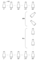
- the acquisition unit 241 holds the container 400 in an upright posture using the gripping device 110 so that its central axis is parallel to the direction of gravity. At this time, the rotation angle of the container 400 around the central axis is set to 0° as shown in FIG.
- the acquisition unit 241 uses the gripping device 110 to rotate the container 400 in one direction from 0° to 360° around its central axis at a constant rotational speed, as shown in FIG.
- the device 130 continuously photographs the liquid near the bottom of the container 400. As a result, images of the vicinity of the bottom surface of the container 400 are obtained at each predetermined angle.
- the image group obtained at this time is called a first image group.
- the acquisition unit 241 uses the gripping device 110 to swing and tilt the container 400, as shown in FIG. 10, and then makes it stand still in an upright state for a certain period of time.
- the liquid in the container 400 flows, and foreign matter with a light specific gravity is made to float in the liquid.
- foreign objects such as metal pieces with large specific gravity only move along the bottom surface of the container 400 even during rocking, and do not necessarily float.
- the acquisition unit 241 uses the gripping device 110 to reversely rotate the container 400 from 360° toward 0° about its central axis at a constant rotation speed, while the camera device 130 Then, the liquid near the bottom of the container 400 is continuously photographed again. As a result, images of the vicinity of the bottom surface of the container 400 are obtained at each predetermined angle.
- the image group obtained at this time is called a second image group.
- the detection unit 242 acquires a difference image between each image included in the second image group acquired by the acquisition unit 241 and an image included in the first image group captured at the same angle, and calculates the difference image. Based on this, foreign matter present on the bottom surface of the container 400 is detected. For example, a scratch on the container 400 on the bottom surface of the container 400 is shown at the same position in the two images taken at the same angle, and therefore does not appear in the difference image. On the other hand, since the foreign matter present on the bottom of the container moves from its original position to another position due to the rocking of the container 400, a shadow appears in the difference image. The acquisition unit 241 detects a shadow appearing in the difference image as a foreign object.
- the detection unit 242 acquires the shape, brightness distribution, size, etc. of the foreign object from the shadow image (image patch) that appears in the difference image. Further, the detection unit 242 calculates a movement trajectory of the foreign object indicating the relative movement of the foreign object with respect to the container 400 from the time series of the difference images. Then, the detection unit 242 determines the type of foreign object based on at least one of the shape, brightness distribution, size, and movement trajectory of the foreign object. For example, the detection unit 242 determines that the object is a piece of glass if there is a large difference in brightness within the shadow area, and determines that it is a piece of metal if there is little difference in brightness.
- the display control unit 243 is configured to display the presence or absence of a foreign object detected on the bottom surface of the container 400 and the type of foreign object on the screen of the display device 300.
- the period of rocking shown in FIG. 10 is a period in which the acquisition unit 241 rocks and tilts the container 400 for a certain period of time, similar to step S1 in FIG.
- the stationary period shown in FIG. 10 is a period during which the acquisition unit 241 continuously photographs the stationary container 400 with the camera device 130, as in step S2 of FIG.
- the types of foreign objects are classified by their materials, such as hair pieces/fiber pieces, plastic pieces, rubber pieces, glass pieces, metal pieces, etc.
- the types of foreign objects may be defined by other than the material. For example, based on the specific gravity of the liquid in the container 400, it may be classified into buoyant foreign objects whose specific gravity is lighter than the liquid, sedimentary foreign objects whose specific gravity is heavier than the liquid, and floating foreign objects whose specific gravity is similar to that of the liquid. .
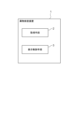
- the foreign object inspection device 1 includes a detection means 2 and a display control means 3.
- the detection means 2 is configured to detect foreign substances present in the liquid and their types from a plurality of images obtained by successively photographing a container filled with liquid.
- the detection means 2 can be configured in the same manner as the detection unit 242 in FIG. 2, for example, but is not limited thereto.
- the display control means 3 is configured to output the type of foreign object detected by the detection means 2 to the display device.
- the display control means 3 can be configured in the same manner as the display control section 243 in FIG. 2, for example, but is not limited thereto.
- the foreign matter inspection device 1 configured as above functions as follows. That is, the detection means 2 detects the foreign matter present in the liquid and its type from a plurality of images obtained by successively photographing a container containing the liquid. Next, the display control means 3 outputs the type of foreign object detected by the detection means 2 to the display device.
- the type of detected foreign object is displayed on the screen of the display device, so that the type of foreign object can be recognized.
- the present invention can be used in the field of detecting foreign substances and their types in liquids such as medicines and pharmaceuticals sealed in containers.
- the display control means further outputs the moving trajectory image of the foreign object to the display device as a still image.
- the display control means further outputs to the possession device an index indicating a location on which the foreign object is detected in the movement trajectory image.
- Foreign matter inspection device according to appendix 2.
- the display control means further outputs the moving trajectory image of the foreign object to the display device as a moving image when the index is specified.
- the display control means further outputs information regarding the cause of the contamination of the foreign matter to the display device.
- the display control means further outputs the type of foreign matter floating in the liquid in the container to the display device.
- the display control means further outputs the type of foreign matter present on the bottom surface of the container to the display device.
- Inspection system 110 Gripping device 120 Lighting device 130 Camera device 200 Inspection device 300 Display device 400 Container 401 Rubber stopper
Landscapes
- Engineering & Computer Science (AREA)
- Theoretical Computer Science (AREA)
- General Physics & Mathematics (AREA)
- Physics & Mathematics (AREA)
- Computer Vision & Pattern Recognition (AREA)
- General Health & Medical Sciences (AREA)
- Health & Medical Sciences (AREA)
- Evolutionary Computation (AREA)
- Medical Informatics (AREA)
- Software Systems (AREA)
- Databases & Information Systems (AREA)
- Computing Systems (AREA)
- Artificial Intelligence (AREA)
- Multimedia (AREA)
- Quality & Reliability (AREA)
- Life Sciences & Earth Sciences (AREA)
- Chemical & Material Sciences (AREA)
- Analytical Chemistry (AREA)
- Biochemistry (AREA)
- Immunology (AREA)
- Pathology (AREA)
- Signal Processing (AREA)
- Image Analysis (AREA)
- Investigating Materials By The Use Of Optical Means Adapted For Particular Applications (AREA)
- Image Processing (AREA)
Priority Applications (4)
| Application Number | Priority Date | Filing Date | Title |
|---|---|---|---|
| JP2024507444A JP7848862B2 (ja) | 2022-03-18 | 2022-03-18 | 異物検査装置 |
| PCT/JP2022/012744 WO2023175943A1 (ja) | 2022-03-18 | 2022-03-18 | 異物検査装置 |
| US18/845,034 US20250182264A1 (en) | 2022-03-18 | 2022-03-18 | Foreign object inspection device |
| EP22932213.6A EP4495584A4 (en) | 2022-03-18 | 2022-03-18 | Foreign matter inspection device |
Applications Claiming Priority (1)
| Application Number | Priority Date | Filing Date | Title |
|---|---|---|---|
| PCT/JP2022/012744 WO2023175943A1 (ja) | 2022-03-18 | 2022-03-18 | 異物検査装置 |
Publications (1)
| Publication Number | Publication Date |
|---|---|
| WO2023175943A1 true WO2023175943A1 (ja) | 2023-09-21 |
Family
ID=88022975
Family Applications (1)
| Application Number | Title | Priority Date | Filing Date |
|---|---|---|---|
| PCT/JP2022/012744 Ceased WO2023175943A1 (ja) | 2022-03-18 | 2022-03-18 | 異物検査装置 |
Country Status (4)
| Country | Link |
|---|---|
| US (1) | US20250182264A1 (https=) |
| EP (1) | EP4495584A4 (https=) |
| JP (1) | JP7848862B2 (https=) |
| WO (1) | WO2023175943A1 (https=) |
Citations (4)
| Publication number | Priority date | Publication date | Assignee | Title |
|---|---|---|---|---|
| CN103743755A (zh) * | 2013-12-20 | 2014-04-23 | 许雪梅 | 一种基于近邻传播聚类的医用药剂中可见异物检测方法 |
| CN109709108A (zh) * | 2019-02-26 | 2019-05-03 | 天津迦自机器人科技有限公司 | 一种瓶装透明液体杂质检测设备及方法 |
| JP2019174346A (ja) * | 2018-03-29 | 2019-10-10 | 富士通株式会社 | 検査方法、検査装置、及び検査プログラム |
| WO2021214994A1 (ja) | 2020-04-24 | 2021-10-28 | 日本電気株式会社 | 検査システム |
Family Cites Families (2)
| Publication number | Priority date | Publication date | Assignee | Title |
|---|---|---|---|---|
| TWI582408B (zh) * | 2011-08-29 | 2017-05-11 | 安美基公司 | 用於非破壞性檢測-流體中未溶解粒子之方法及裝置 |
| CN110603542B (zh) * | 2017-06-07 | 2023-04-25 | 赫尔实验室有限公司 | 用于视觉活动识别的系统、方法和计算机可读介质 |
-
2022
- 2022-03-18 US US18/845,034 patent/US20250182264A1/en active Pending
- 2022-03-18 EP EP22932213.6A patent/EP4495584A4/en active Pending
- 2022-03-18 JP JP2024507444A patent/JP7848862B2/ja active Active
- 2022-03-18 WO PCT/JP2022/012744 patent/WO2023175943A1/ja not_active Ceased
Patent Citations (4)
| Publication number | Priority date | Publication date | Assignee | Title |
|---|---|---|---|---|
| CN103743755A (zh) * | 2013-12-20 | 2014-04-23 | 许雪梅 | 一种基于近邻传播聚类的医用药剂中可见异物检测方法 |
| JP2019174346A (ja) * | 2018-03-29 | 2019-10-10 | 富士通株式会社 | 検査方法、検査装置、及び検査プログラム |
| CN109709108A (zh) * | 2019-02-26 | 2019-05-03 | 天津迦自机器人科技有限公司 | 一种瓶装透明液体杂质检测设备及方法 |
| WO2021214994A1 (ja) | 2020-04-24 | 2021-10-28 | 日本電気株式会社 | 検査システム |
Non-Patent Citations (1)
| Title |
|---|
| See also references of EP4495584A4 |
Also Published As
| Publication number | Publication date |
|---|---|
| JPWO2023175943A1 (https=) | 2023-09-21 |
| EP4495584A4 (en) | 2025-05-07 |
| JP7848862B2 (ja) | 2026-04-21 |
| EP4495584A1 (en) | 2025-01-22 |
| US20250182264A1 (en) | 2025-06-05 |
Similar Documents
| Publication | Publication Date | Title |
|---|---|---|
| JP7359297B2 (ja) | 検査システム | |
| JP7216146B2 (ja) | 流体中の非溶解粒子の非破壊的検出のための方法および装置 | |
| JP7529151B2 (ja) | 検査システム | |
| JP4517826B2 (ja) | 液面検出方法 | |
| EP3259578A1 (en) | Model-based methods and apparatus for classifying an interferent in specimens | |
| JP7234502B2 (ja) | 方法、装置、及びプログラム | |
| JP2004354100A (ja) | 容器内液体中の異物検出方法及びその装置 | |
| JPS5937451A (ja) | 対象物の透明度のコントラストにより対象物を検査する方法及び装置 | |
| US20100220919A1 (en) | Method and installation for detecting foreign bodies inside a container | |
| CN103119395A (zh) | 玻璃瓶检查装置 | |
| JP2001116703A (ja) | 容器内浮遊物判別方法及びその装置 | |
| JP5635963B2 (ja) | 飲料液異物検査装置および飲料液異物検査方法 | |
| JP2004257937A (ja) | 異物検査装置および検査方法 | |
| WO2023175943A1 (ja) | 異物検査装置 | |
| WO2025027717A1 (ja) | 検査装置 | |
| JP7574944B2 (ja) | 学習装置 | |
| WO2025154143A1 (ja) | 検査装置 | |
| US20260098817A1 (en) | Inspection system | |
| WO2025154144A1 (ja) | 検査装置 | |
| WO2023105724A1 (ja) | 異物検査装置 | |
| US20260086040A1 (en) | Inspection system | |
| JPH0275941A (ja) | 検びん装置 | |
| JPH0196540A (ja) | 液体中の異物検出方法 | |
| WO2024176360A1 (ja) | 情報処理装置 | |
| JP2001134762A (ja) | 瓶類の選別装置 |
Legal Events
| Date | Code | Title | Description |
|---|---|---|---|
| 121 | Ep: the epo has been informed by wipo that ep was designated in this application |
Ref document number: 22932213 Country of ref document: EP Kind code of ref document: A1 |
|
| ENP | Entry into the national phase |
Ref document number: 2024507444 Country of ref document: JP Kind code of ref document: A |
|
| WWE | Wipo information: entry into national phase |
Ref document number: 18845034 Country of ref document: US |
|
| WWE | Wipo information: entry into national phase |
Ref document number: 2022932213 Country of ref document: EP |
|
| NENP | Non-entry into the national phase |
Ref country code: DE |
|
| ENP | Entry into the national phase |
Ref document number: 2022932213 Country of ref document: EP Effective date: 20241018 |
|
| WWP | Wipo information: published in national office |
Ref document number: 18845034 Country of ref document: US |