WO2023175943A1 - 異物検査装置 - Google Patents
異物検査装置 Download PDFInfo
- Publication number
- WO2023175943A1 WO2023175943A1 PCT/JP2022/012744 JP2022012744W WO2023175943A1 WO 2023175943 A1 WO2023175943 A1 WO 2023175943A1 JP 2022012744 W JP2022012744 W JP 2022012744W WO 2023175943 A1 WO2023175943 A1 WO 2023175943A1
- Authority
- WO
- WIPO (PCT)
- Prior art keywords
- container
- foreign
- foreign matter
- display device
- liquid
- Prior art date
Links
Images


Classifications
-
- G—PHYSICS
- G01—MEASURING; TESTING
- G01N—INVESTIGATING OR ANALYSING MATERIALS BY DETERMINING THEIR CHEMICAL OR PHYSICAL PROPERTIES
- G01N21/00—Investigating or analysing materials by the use of optical means, i.e. using sub-millimetre waves, infrared, visible or ultraviolet light
- G01N21/84—Systems specially adapted for particular applications
- G01N21/88—Investigating the presence of flaws or contamination
- G01N21/90—Investigating the presence of flaws or contamination in a container or its contents
Definitions
- the present invention relates to a foreign matter inspection device, a foreign matter inspection method, and a recording medium.
- a device has been proposed that inspects the presence or absence of foreign matter in a liquid sealed in a container.
- the moving trajectory of floating objects is calculated from a plurality of images obtained by continuously photographing liquid in a container with a camera, and based on the characteristics of the moving trajectory, floating objects are determined to be air bubbles or foreign objects.
- the determination result is displayed on the screen of the display device.
- An object of the present invention is to provide a foreign matter inspection device that solves the above-mentioned problems.
- a foreign matter inspection device includes: a detection means for detecting foreign substances present in the liquid and their types from a plurality of images obtained by sequentially photographing a container filled with the liquid; a display control means for outputting the type of the detected foreign object to a display device; It is configured to include.
- a foreign substance inspection method includes: Detecting foreign objects present in the liquid and their types from a plurality of images obtained by sequentially photographing a container containing the liquid, outputting the type of the detected foreign object to a display device; It is configured as follows.
- a computer-readable recording medium includes: to the computer, A process of detecting foreign substances present in the liquid and their types from a plurality of images obtained by sequentially photographing a container containing the liquid; a process of outputting the type of the detected foreign object to a display device;
- the computer is configured to record a program that performs the following.
- the present invention outputs the type of detected foreign object to the display device, so that the type of foreign object can be recognized.
- FIG. 1 is a block diagram of an inspection system according to a first embodiment of the present invention. It is a block diagram showing an example of an inspection device in a 1st embodiment of the present invention.
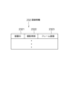
- FIG. 3 is a diagram illustrating a configuration example of image information in the first embodiment of the present invention.
- FIG. 3 is a diagram illustrating a configuration example of tracking information in the first embodiment of the present invention. It is a figure showing an example of composition of test result information in a 1st embodiment of the present invention.
- FIG. 3 is a schematic diagram showing an example of a moving trajectory still image that visualizes moving trajectory information of a foreign object in the first embodiment of the present invention.
- FIG. 3 is a diagram showing an example of the configuration of foreign matter contamination factor information in the first embodiment of the present invention.
- FIG. 2 is a block diagram of a foreign matter inspection device according to a second embodiment of the present invention.
- FIG. 1 is a block diagram of an inspection system 100 according to a first embodiment of the present invention.
- an inspection system 100 is a system that inspects the presence or absence of foreign substances in a liquid sealed in a container 400.
- the inspection system 100 includes a gripping device 110, a lighting device 120, a camera device 130, an inspection device 200, and a display device 300 as main components.
- the container 400 is a transparent or translucent container such as a glass bottle or a plastic bottle.
- the inside of the container 400 is sealed and filled with a liquid such as a medicine or water. Further, there is a possibility that foreign matter is mixed into the liquid sealed in the container 400. Examples of foreign objects include glass pieces, plastic pieces, rubber pieces, hair pieces/fiber pieces, metal pieces, and the like.
- the gripping device 110 is configured to grip the container 400 in a predetermined posture.
- the predetermined posture is arbitrary.
- the predetermined posture may be the posture when the container 400 is upright.
- the predetermined posture may be a posture in which the container 400 is tilted at a predetermined angle from an upright posture.
- a posture in which the container 400 stands upright will be described as a predetermined posture.
- Any mechanism can be used to hold the container 400 in an upright position.
- the gripping mechanism includes a pedestal on which the container 400 is placed in an upright position, and a member that presses the top surface of the rubber stopper 401, which is the top of the container 400 placed on the pedestal. It's good that it has been done.
- the gripping device 110 is configured to rotate, tilt, or swing the container 400 in a predetermined direction from an upright position while gripping the container 400.
- the mechanism for rotating, tilting, and rocking the container 400 is arbitrary.
- the mechanism for rotating, tilting, and swinging may include a motor that rotates, tilting, and swinging the entire gripping mechanism while holding the container 400.
- the gripping device 110 is connected to the inspection device 200 by wire or wirelessly.
- the gripping device 110 rotates, tilts, and swings the container 400 in a predetermined direction from an upright posture while gripping the container 400.
- the gripping device 110 stops the operations of rotating, tilting, and rocking the container 400, and returns to the state of gripping the container 400 in an upright posture.
- the illumination device 120 is configured to irradiate the liquid sealed in the container 400 with illumination light.
- the lighting device 120 is, for example, a surface light source whose size corresponds to the size of the container 400.
- the lighting device 120 is installed on the opposite side of the container 400 from the side where the camera device 130 is installed. That is, the illumination by the illumination device 120 is transmitted illumination.
- the position of the illumination device 120 is not limited to this, and the illumination device 120 may be installed, for example, on the bottom side of the container 400 or in a position adjacent to the camera device 130 to take a picture using reflected light illumination.
- the camera device 130 is a high-speed photographing device that continuously photographs the liquid inside the container 400 at a predetermined high frame rate from a predetermined position on the opposite side of the container 400 to the side where the illumination device 120 is installed.
- the camera device 130 may include, for example, a color camera or a monochrome camera equipped with a CCD (Charge-Coupled Device) image sensor or a CMOS (Complementary MOS) image sensor having a pixel capacity of several million pixels.
- the camera device 130 is connected to the inspection device 200 by wire or wirelessly.
- the camera device 130 is configured to transmit time-series images obtained by photographing to the inspection device 200 together with information indicating the time of photographing.
- the display device 300 is a display device such as an LCD (Liquid Crystal Display).
- the display device 300 is connected to the inspection device 200 by wire or wirelessly.
- the display device 300 is configured to display the results of an inspection of the container 400 performed by the inspection device 200 and the like.
- the inspection device 200 is an information processing device that performs image processing on time-series images taken by the camera device 130 to inspect the presence or absence of foreign objects in the liquid sealed in the container 400 and the type of foreign objects. It is.
- the inspection device 200 is connected to the gripping device 110, the camera device 130, and the display device 300 by wire or wirelessly.
- FIG. 2 is a block diagram showing an example of the inspection device 200.
- the inspection device 200 includes a communication I/F section 210, an operation input section 220, a storage section 230, and an arithmetic processing section 240.
- the communication I/F section 210 is composed of a data communication circuit, and is configured to perform data communication with the gripping device 110, the camera device 130, the display device 300, and other external devices (not shown) by wire or wirelessly.
- the operation input unit 220 includes an operation input device such as a keyboard and a mouse, and is configured to detect an operator's operation and output it to the arithmetic processing unit 240.
- the storage unit 230 is composed of one or more types of storage devices such as a hard disk or memory, and is configured to store processing information and programs 231 necessary for various processes in the arithmetic processing unit 240.
- the program 231 is a program that implements various processing units by being read and executed by the arithmetic processing unit 240.
- the information is read in advance and stored in the storage unit 230.
- the main processing information stored in the storage unit 230 includes image information 232, tracking information 233, test result information 234, and foreign matter contamination factor information 236.
- the image information 232 includes time-series images obtained by continuously photographing the liquid in the container 400 using the camera device 130. If floating objects are present in the liquid in the container 400, the image information 232 includes an image of the floating objects.
- FIG. 3 shows a configuration example of the image information 232.
- the image information 232 in this example is composed of entries consisting of a set of a container ID 2321, a photographing time 2322, and a frame image 2323.
- An ID that uniquely identifies the container 400 is set in the container ID 2321 item.
- Possible examples of the container ID 2321 include a serial number assigned to the container 400, a bar code affixed to the container 400, and object fingerprint information collected from the rubber stopper 401 of the container 400.
- the photographing time and frame image are set in each item of photographing time 2322 and frame image 2323.
- the photographing time 2322 is set to an accuracy (for example, in milliseconds) that allows the frame image to be distinguished from other frame images of the same container ID.
- the photographing time 2322 for example, the elapsed time from the time when the rotation, tilting, and rocking of the container 400 is stopped may be used.
- the container ID 2321 is associated with each frame image 2323, but the container ID 2321 may be associated with each group of a plurality of frame images 2323.
- the tracking information 233 includes time-series data representing the movement locus of the floating object that is tracked by detecting an image of the floating object present in the liquid in the container 400.
- FIG. 4 shows an example of the configuration of the tracking information 233.
- the tracking information 233 in this example is composed of entries of a container ID 2331, a set of a tracking ID 2332, and a pointer 2333.
- An ID that uniquely identifies the container 400 is set in the container ID 2331 entry.
- An entry consisting of a pair of tracking ID 2332 and pointer 2333 is provided for each floating object to be tracked.
- an ID for identifying the floating object to be tracked from other floating objects in the same container 400 is set.
- a pointer to movement trajectory information 2334 of the floating object to be tracked is set.
- the movement trajectory information 2334 is composed of entries consisting of a set of time 23341, position information 23342, size 23343, brightness distribution 23344, and shape 23345.
- the time 23341, position information 23342, size 23343, brightness distribution 23344, and shape 23345 items include the shooting time, coordinate values indicating the position of the floating object to be tracked at the shooting time, the size of the floating object, and the inside of the floating object area.
- the brightness distribution and the shape of the floating object are set.
- the photographing time 2322 of the frame image is used as the photographing time set to the time 23341.
- the coordinate values may be, for example, coordinate values in a predetermined coordinate system.
- the predetermined coordinate system may be a camera coordinate system centered on the camera, or a world coordinate system centered on a certain position in real space.
- Entries of movement trajectory information 2334 are arranged in order of time 23341.
- the time 23341 of the first entry is the tracking start time.
- the time 23341 of the last entry is the tracking end time.
- the times 23341 of entries other than the first and last entries are tracking intermediate times.
- the test result information 234 includes information according to the test results of the container 400.
- FIG. 5 shows a configuration example of the test result information 234.
- the inspection result information 234 in this example is based on the following entries: container ID 2341, inspection result 2342, number of detected foreign objects 2343, number of bubbles detected 2344, set of detected foreign object ID 2345 and pointer 2346, and set of detected air bubble ID 2347 and pointer 2348. It is configured.
- An ID that uniquely identifies the container 400 to be inspected is set in the container ID 2341 entry.
- an OK inspection pass
- NG inspection failure
- the total number of detected foreign objects and/or the total number of foreign objects for each type are set.
- the total number of detected bubbles is set in the entry 2344 for the number of detected bubbles.
- An entry consisting of a detected foreign object ID 2345 and a pointer 2346 is provided for each detected foreign object.
- an ID for distinguishing the detected foreign object from other foreign objects in the same container 400 is set.
- a pointer to detected foreign object information 2349 of the detected foreign object is set.
- An entry for a pair of detected bubble ID 2347 and pointer 2348 is provided for each detected bubble.
- an ID for distinguishing the detected bubble from other bubbles in the same container 400 is set.
- a pointer to detected bubble information 2350 of the detected bubble is set.
- the detected foreign object information 2349 is composed of the following entries: a pair of a tracking ID 23491 and a pointer 23492, a foreign object type 23493, a movement trajectory still image 23494, and a movement trajectory video 23495.
- the tracking ID 2332 of the detected foreign object is set in the tracking ID 23491 item.
- a pointer to the movement trajectory information 2334 of the detected foreign object is set.
- the determined foreign material type is set in the foreign material type 23493 entry.
- the probability of the determination result may be further set in the foreign object type entry 23493.
- the probability of a determination result is an index representing the certainty of the determination result.
- FIG. 6 is a schematic diagram showing an example of a moving trajectory still image 23494.
- the moving trajectory still image 23494 in this example is a composite image in which the background image 234941 and the moving trajectory image 234942 are superimposed.
- the background image 234941 for example, the most reliable frame image in which the detected foreign object is determined to be a specific type of foreign object rather than a bubble may be used.
- the background image 234941 may be a frame image other than the above, for example, any frame image in which a detected foreign object is captured.
- the movement trajectory image 234942 includes lines representing the movement trajectory of the foreign object. In the example of FIG. 6, broken lines are used, but solid lines may also be used. Further, the moving trajectory image 234942 has an arrow added thereto indicating the moving direction of the foreign object. However, the form representing the moving direction of the foreign object is not limited to the arrow.
- the method of moving the foreign object may be expressed by changing the line type, width, color, etc. of the line representing the movement trajectory of the foreign object as time passes.
- the display form of the moving trajectory image 234942 may be changed depending on the moving speed of the foreign object. For example, the moving speed of the foreign object may be expressed by changing the line type, width, color, etc. of the line depending on the moving speed of the foreign object.
- a display column 234943 that displays the type of foreign object is drawn in the moving trajectory still image 23494.
- the type of foreign object set in the foreign object type 23493 is displayed, for example, in text.
- an index 234944 is drawn on the moving trajectory still image 23494 to indicate a location that serves as a basis for determining a foreign object.
- the index 234944 is a rectangle surrounding the location that is the basis for determination, but is not limited thereto.
- the location serving as the basis for determining a foreign object means a location in the movement trajectory information where it is determined that the foreign object is not a bubble but a specific type of foreign object.
- a metal piece such as a stainless steel piece has a high specific gravity, it is less affected by the movement of the liquid, and a falling trajectory can be obtained in a substantially straight line. Therefore, the location where the object is falling in a straight line becomes the location that is the basis for determining that it is a metal piece. Furthermore, in the case of a foreign object such as a piece of rubber having a specific gravity smaller than that of a metal piece, a place where the foreign object has settled down to a lower position than the position at the tracking start time can be a place that becomes the basis for determination.
- the detected bubble information 2350 is composed of entries of a pair of tracking ID 23501 and pointer 23502, determination result 23503, movement trajectory still image 23504, and movement trajectory video 23505.
- the tracking ID 2332 of the detected bubble is set in the tracking ID 23501 item.
- a pointer to movement trajectory information 2334 of the detected bubble is set in the item 23502 of pointer.
- text indicating that the determination result is "bubbles" is set.
- a probability of the judgment result may be further set.
- At least one still image that visualizes the movement trajectory information 2334 of the detected bubble is set in the movement trajectory still image 23504 entry.
- a moving image that visualizes the moving trajectory information 2334 of the detected bubble is set.
- the foreign matter contamination factor information 236 includes information regarding the cause of foreign matter contamination in the container 400.
- FIG. 7 shows an example of the foreign matter contamination factor information 236.
- the foreign matter contamination factor information 236 is composed of a plurality of entries 2361, and each entry 2361 is composed of a pair of a foreign matter type 23611 and a factor 23612.
- hair pieces/fiber pieces, plastic pieces, rubber pieces, glass pieces, and metal pieces are set in the foreign object type 23611 item.
- Factor 23612 also includes, for example, "person” for hair/fiber pieces, "container” for plastic and glass pieces, “container stopper” for rubber pieces, and metal pieces.
- "Manufacturing equipment” is set respectively. This means, for example, that the metal piece is a foreign object originating from manufacturing equipment.
- the arithmetic processing unit 240 has a microprocessor such as an MPU and its peripheral circuits, and by reading and executing a program 231 from the storage unit 230, the above hardware and the program 231 cooperate to realize various processing units. is configured to do so.
- the main processing units realized by the arithmetic processing unit 240 include an acquisition unit 241, a detection unit 242, and a display control unit 243.
- the acquisition unit 241 is configured to control the gripping device 110 and the camera device 130 to acquire image information 232 depicting an image of floating objects present in the liquid sealed in the container 400. Further, the acquisition unit 241 is configured to acquire tracking information 233 including time-series data representing the movement trajectory of the floating object by analyzing the image information 232.
- the detection unit 242 is configured to detect whether or not a foreign object is present in the liquid in the container 400 based on the tracking information 233 acquired by the acquisition unit 241, and further to detect the type of foreign object present. . Furthermore, the detection unit 242 is configured to create test result information 234 based on the detection results and store it in the storage unit 230.
- the display control unit 243 is configured to output the test result information 234 to the display device 300 as soon as possible after the test result information 234 is created by the detection unit 242.
- FIG. 8 is a flowchart showing an example of the operation of the inspection system 100 from the start of inspection to the end of inspection for one container 400.
- the acquisition unit 241 induces the flow of liquid within the container 400 (step S1).
- the acquisition unit 241 rotates, tilts, and swings the container 400 using the gripping device 110, and then holds the container 400 still in an upright posture.
- the acquisition unit 241 continuously images the liquid in the container 400 with the camera device 130 under transmitted illumination by the illumination device 120, thereby capturing images over a predetermined length of time at a predetermined frame rate.
- a time series of images is acquired (step S2).
- the time-series images acquired from the camera device 130 by the acquisition unit 241 are stored in the storage unit 230 as image information 232.
- the image information 232 includes an entry consisting of a set of a container ID 2321, a photographing time 2322, and a frame image 2323.
- the detection unit 242 detects floating objects present in the liquid in the time-series images included in the image information 232 (step S3).
- the detection unit 242 tracks the detected floating object in the time-series images included in the image information 232 (step S4).
- the detection unit 242 stores the tracking results of each of the tracked floating objects in the storage unit 230 as tracking information 233.
- the tracking information 233 includes movement trajectory information 2334 for each floating object to be tracked. Further, a plurality of entries of movement trajectory information 2334 are arranged in order of time 23341, and each entry has position information 23342, size 23343, brightness distribution 23344, and shape 23345 of the floating object to be tracked.
- the detection unit 242 determines whether the floating object is a foreign object or a bubble based on the movement trajectory information 2334 of the floating object. Furthermore, the type of floating matter that is a foreign matter is determined (step S5). Next, the detection unit 242 creates inspection result information 234 recording the determination results for each floating object, and stores it in the storage unit 230 (step S6). As illustrated in FIG. 5, the inspection result information 234 includes a container ID 2341, an inspection result 2342, the number of detected foreign objects 2343, the number of bubbles detected 2344, detected foreign object information 2349 for each detected foreign object, and detected air bubbles for each detected air bubble. Contains information 2350.
- the detected foreign object information 2349 includes a foreign object type 23493, a moving trajectory still image 23494, a moving trajectory moving image 23495, and the like.
- the detected bubble information 2350 includes a determination result (bubble) 23503, a movement trajectory still image 23504, a movement trajectory video 23505, and the like.
- the display control unit 243 outputs the test result information 234 of the container 400 to the display device 300 (step S7).
- the acquisition unit 241 first rotates, tilts, and swings the container 400 to be inspected by activating the gripping device 110 that grips the container 400 in an upright posture. Next, after a certain period of time has passed after activation, the acquisition unit 241 stops the gripping device 110 to keep the container 400 still in a predetermined posture. In this way, by tilting, rocking, and rotating the container 400 for a certain period of time and then letting it stand still, a state is obtained in which the liquid flows due to inertia within the stationary container 400. Next, the acquisition unit 241 starts an operation of continuously photographing the liquid in the container 400 at a predetermined frame rate with the camera device 130 under transmitted illumination by the illumination device 120. That is, assuming that time Ts is the time when the container 400 comes to rest after being rotated, tilted, and swung, the acquisition unit 241 starts the above-mentioned photographing operation from time Ts.
- the acquisition unit 241 continues to continuously photograph the liquid in the container 400 with the camera device 130 from time Ts until time Te at which a predetermined time Tw has elapsed.
- the predetermined time Tw is set such that, for example, if it is assumed that all floating objects floating in the liquid are bubbles, all the bubbles move upwards in the container 400 and are no longer expected to move downwards.
- the length of time may be set to be longer than the time required to obtain a suitable movement trajectory (hereinafter referred to as the minimum imaging time length).
- the minimum imaging time length may be determined in advance through experiments or the like, and may be fixedly set in the acquisition unit 241. Note that, when the time Te is reached, the acquisition unit 241 may immediately stop photographing by the camera device 130, or may continue photographing by the camera device 130.
- the acquisition unit 241 adds a photographing time and a container ID to each of the time-series frame images acquired from the camera device 130, and stores them as image information 232 in the storage unit 230.
- the acquisition unit 241 detects the shadow of the floating object in the liquid in the container 400 from each of these frame images. For example, the acquisition unit 241 detects the shadow of floating objects in the liquid by a method described below. However, the acquisition unit 241 may detect the shadow of floating objects in the liquid using methods other than those described below.
- the acquisition unit 241 performs binarization processing on each frame image to create a binarized frame image.
- the acquisition unit 241 detects the shadow of floating objects from each of the binarized frame images in the following manner.
- the acquisition unit 241 sets the binarized frame image from which the shadow of the floating object is to be detected as the binarized frame image of interest.
- a difference image between the binarized frame image of interest and a binarized frame image whose photographing time is after ⁇ t is generated.
- ⁇ t is set to a time such that the same floating objects partially overlap in the two images, or even if they do not overlap, they appear at very close positions. Therefore, the time difference ⁇ t is determined depending on the properties of the liquid and foreign matter, the flow state, and the like.
- the matching image portions of the two binarized frame images are erased, and only the different image portions are left.
- the acquisition unit 241 detects a shadow in the binarized frame image of interest corresponding to a location where a shadow appears in the difference image as a shadow of a floating object present in the binarized frame image of interest.
- the acquisition unit 241 tracks the detected floating objects in the time-series images, and creates tracking information 233 according to the tracking results.
- the acquisition unit 241 initializes the tracking information 233.
- the container ID of container 400 is set in the entry of container ID 2331 in FIG.
- the acquisition unit 241 tracks floating objects in the time-series images by the method described below, and assigns the tracking ID 2332 and pointer in FIG. 4 for each floating object according to the tracking results. 2333, and movement trajectory information 2334 is created.
- the acquisition unit 241 focuses on the binarized frame image whose photographing time is the latest among the time series of the binarized frame images created above.
- the acquisition unit 241 assigns a unique tracking ID to each floating object detected in the binarized frame image of interest.
- the acquisition unit 241 sets the tracking ID given to the floating object detected in the binarized frame image of interest in the tracking ID 2332 item in FIG.
- the coordinate values, size, brightness distribution, and shape of floating objects in the medium binarized frame image are set.
- the acquisition unit 241 shifts its attention to the binarized frame image that is one frame after the binarized frame image currently being focused on.
- the acquisition unit 241 focuses on one of the floating objects detected in the binarized frame image of interest.
- the acquisition unit 241 compares the position of the floating object of interest with the position of the floating object detected in the binarized frame image one frame before (hereinafter referred to as the preceding binarized frame image). If the floating object exists within a predetermined threshold distance from the floating object of interest, it is determined that the floating object of interest and the floating object existing within the threshold distance are the same floating object.
- the acquisition unit 241 assigns to the floating object of interest the tracking ID that has been assigned to the floating object that has been determined to be the same floating object. Then, the acquisition unit 241 secures a new entry in the movement trajectory information 2334 pointed to by the pointer 2333 of the entry of the tracking information 233 to which the assigned tracking ID 2332 is set, and stores the time 23341 and position information 23342 of the secured entry. In the size 23343, brightness distribution 23344, and shape 23345, the photographing time of the binarized frame image of interest, the coordinate value, size, brightness distribution, and shape of the floating object of interest are set.
- the acquisition unit 241 determines that the floating object of interest is a new floating object, and assigns a new tracking ID. .
- the acquisition unit 241 sets the tracking ID assigned to the floating object of interest in the item of tracking ID 2332 in FIG. Setting the shooting time of the binarized frame image while paying attention to the entry time 23341, and paying attention to the items 23342, size 23343, brightness distribution 23344, and shape 23345 of the floating object. and shape.
- the acquisition unit 241 When the acquisition unit 241 finishes processing the floating object of interest, it shifts its attention to the next floating object detected in the binarized frame image of interest, and repeats the same process as described above. When the acquisition unit 241 finishes noting all the floating objects detected in the binarized frame image under attention, it shifts its attention to the frame image one frame later, and repeats the same process as described above. Then, when the acquisition unit 241 finishes paying attention to the last frame image in the image information 232, it ends the tracking process.
- the acquisition unit 241 performed tracking based on the distance between floating objects in two adjacent frame images.
- the acquisition unit 241 may perform tracking based on the distance between floating objects in two adjacent frame images with n frames (n is a positive integer of 1 or more) in between.
- the acquisition unit 241 obtains tracking results based on the distance between floating objects in two adjacent frame images with m frames (m is a positive integer greater than or equal to 0) in between, and m+j frames (j is a positive integer of 0 or more). Tracking may be performed by comprehensively determining the tracking result based on the distance between floating objects in two adjacent frame images (a positive integer of 1 or more).
- the detection unit 242 reads the tracking information 233 from the storage unit 230 and identifies the type (class) of the floating object based on the movement trajectory information 2334 of the floating object included in the tracking information 233. .
- the number of identified classes can be, for example, a total of 7 classes including a bubble class, a hair piece/fiber piece class, a plastic piece class, a rubber piece class, a glass piece class, a metal piece class, and other classes, but is not limited thereto. , is optional as long as there are two or more classes.
- the detection unit 242 detects that the characteristics of the movement trajectory of the floating object and the appearance characteristics (shape, brightness distribution, size) of the floating object are different between bubbles and foreign objects, which are recognized from the floating object movement trajectory information 2334. , and also uses the differences depending on the type of foreign object to identify the class of each floating object.
- Air bubbles which have a much lower specific gravity than the liquid, have a strong tendency to move in the anti-gravity direction in the liquid.
- foreign matter that has a higher specific gravity than air bubbles does not have a strong tendency to move in the counter-gravity direction in the liquid, and this tendency becomes more pronounced as the foreign matter has a higher specific gravity.
- hair pieces and fiber pieces tend to float in the liquid because the difference in specific gravity between them and the liquid is not large.
- Plastic pieces have a lower specific gravity than the liquid, although not as much as air bubbles, so they tend to float near the liquid surface. Rubber pieces, glass pieces, and metal pieces have a higher specific gravity than the liquid, so they tend to float or be located near the bottom surface.
- Bubbles and foreign matter have the following differences in appearance. Bubbles tend to have a hollow shape such as a ring shape or a donut shape, but foreign matter does not have such a tendency. Furthermore, hair pieces and fiber pieces often have an elongated shape. A piece of glass tends to have a large difference in brightness within the detection area (floating object area), whereas a piece of metal has almost no difference in brightness within the detection area.
- the detection unit 242 inputs the movement trajectory information 2334 of the floating object into a trained learning model that has undergone machine learning for estimating the class of the floating object from the movement trajectory information of the floating object, and identifies the floating object.
- the classification may be configured to acquire a class and a discrimination score from the learning model, and determine the discrimination class with the maximum discrimination score as the discrimination class of the floating object.
- the learning model can be generated in advance, for example, by machine learning using a machine learning algorithm such as a neural network, using pairs of floating object movement trajectory information and correct labels representing the floating object's class as training data.
- the method by which the detection unit 242 identifies the class of the floating object based on the moving trajectory information 2334 of the floating object is not limited to the above method, and a rule-based model may be used.
- the detection unit 242 creates inspection result information 234 according to the determination result for each floating object movement trajectory information 2334, and stores it in the storage unit 230. For example, the detection unit 242 first creates initialized test result information 234 in the storage unit 230, and sets the container ID 2331 of the tracking information 233 in the entry of the container ID 2341 of the test result information 234. Next, the detection unit 242 counts the total number of floating objects determined to be foreign objects, and if the counted value is 0, sets OK (inspection passed) in the entry of the inspection result 2342 of the inspection result information 234, The value 0 is set in the entry for the number of foreign objects detected 2343.
- the detection unit 242 sets NG (inspection failure) in the entry of the inspection result 2342 of the inspection result information 234, and sets the entry of the number of detected foreign objects 2343 to NG (inspection failure). Set the total number of floating objects that are determined to be foreign objects.
- the detection unit 242 counts the total number of floating objects determined to be bubbles, and sets the counted value in the entry of the number of bubbles detected 2344 in the test result information 234.
- the detection unit 242 adds an entry of a detected foreign object ID 2345 and a pointer 2346, and detected foreign object information 2349 indicated by the pointer 2346 to the inspection result information 234. create. Further, the detection unit 242 sets an ID such as a serial number for distinguishing the foreign object detected from the container 400 to be inspected identified by the container ID 2341 from other foreign objects in the item of the detected foreign object ID 2345. Further, the detection unit 242 sets the tracking ID 2332 assigned in the tracking information 233 to the floating object determined to be a foreign object in the item of tracking ID 23491 in the detected foreign object information 2349.
- the detection unit 242 sets a pointer to the movement trajectory information 2334 in the pointer 23492 item. Furthermore, the detection unit 242 sets the determined foreign object type in the foreign object type 23493 entry. Furthermore, the detection unit 242 sets a still image that visualizes the movement trajectory information 2334 of the detected foreign object in the entry of the movement trajectory still image 23494. Furthermore, the detection unit 242 sets a moving image that visualizes the movement trajectory information 2334 of the detected foreign object in the entry of the movement trajectory video 23495.
- the detection unit 242 adds an entry of a pair of detected bubble ID 2347 and a pointer 2348, and detected bubble information 2350 indicated by the pointer 2348 to the inspection result information 234. create.
- the detection unit 242 sets an ID such as a serial number for distinguishing the bubble detected from the container 400 to be inspected identified by the container ID 2341 from other bubbles in the detected bubble ID 2347 item.
- the detection unit 242 sets the tracking ID 2332 given in the tracking information 233 to the floating object determined to be a bubble in the item of tracking ID 23501 in the detected bubble information 2350.
- the detection unit 242 sets a pointer to the movement trajectory information 2334 in the pointer 23502 item.
- the detection unit 242 sets text indicating that the bubble is a bubble in the entry of the determination result (bubble) 23503. Further, the detection unit 242 sets a still image that visualizes the movement trajectory information 2334 in the entry of the movement trajectory still image 23504. Furthermore, the detection unit 242 sets a moving image that visualizes the moving trajectory information 2334 in the entry of the moving trajectory video 23505.
- the display control unit 243 performs control to output the test result information 234 to the display device 300.
- the display control unit 243 reads the inspection result information 234 from the storage unit 230 as soon as the detection unit 242 creates the inspection result information 234 for the container 400 to be inspected.
- the display control unit 243 creates a test result display screen based on the read test result information 234.
- the display control unit 243 causes the display device 300 to display the created test result display screen.
- FIG. 9 shows an example of the test result display screen 1000 displayed on the display device 300.
- the display control unit 243 displays a progress status indicator 1001, a foreign object presence/absence indicator 1002, a total indicator 1003, and a moving trajectory still image 1004 on the inspection result display screen.
- the progress indicator 1001 indicates a state in which the container 400 to be inspected has been carried into the inspection device 200, a state in which the carried container 400 is being inspected by the inspection device 200, and a state in which the inspection device 200 has finished inspecting the container.
- the state in which the 400 is being carried out is displayed.
- Foreign object presence indicator 1002 indicates whether at least one foreign object has been detected in container 400 under inspection.
- Cumulative total indicator 1003 displays the total number of containers with no foreign matter and the total number of containers with foreign matter out of all the containers 400 that have been inspected up to this point.
- the movement trajectory still image 1004 displays the movement trajectory still image described with reference to FIG.
- the display control unit 243 controls the display field 234943 to The factor set in the foreign material contamination factor information 236 corresponding to the type of foreign material displayed in 234943 is acquired and displayed on the screen of the display device 300. This allows the operator of the inspection device 200 to immediately recognize the cause of foreign matter contamination.
- the display control unit 243 When the indicator 234944 indicating the location on which the foreign object is determined, which is displayed on the moving trajectory still image 1004 of the inspection result display screen 1000, is designated by the operator through the operation input unit 220 by clicking, etc., the display control unit 243 The moving trajectory moving image 23495 of the detected foreign object information 2349 holding this moving trajectory still image 1004 is read out from the storage unit 230, and the read moving trajectory moving image 23495 is reproduced and displayed on the screen of the display device 300. At this time, the display control unit 243 may reproduce and display only the moving trajectory video 23495, or may synthesize videos of the moving trajectories of all foreign objects detected from the same container 400 and display the moving trajectory video 23495 on the screen of the display device 300. Furthermore, moving images of the movement trajectories of all foreign objects and bubbles detected from the same container 400 may be combined and displayed on the screen of the display device 300.
- the inspection device 200 detects foreign objects present in the liquid and their types from a plurality of images obtained by sequentially photographing the container 400 in which the liquid is sealed. and a display control section 243 that displays the type of detected foreign object on the display device 300. Therefore, the operator of the inspection device 200 and the like can immediately recognize not only that a foreign substance has been mixed into the liquid in the container 400, but also the type of foreign substance. Therefore, the route of foreign matter contamination can be identified more easily and quickly than when the type of foreign matter is not displayed.
- the acquisition unit 241 rotates, tilts, and swings the container 400 using the gripping device 110 and then holds the container 400 still in an upright posture, and continuously captures the liquid in the container 400 in the still state using the camera device 130.
- Image information 232 was acquired by taking an image.
- foreign objects such as metal pieces with high specific gravity may move along the bottom surface and may not float.
- the metal pieces that have been moving on the bottom surface stop moving, so they may be regarded as scratches on the container and not be detected.
- the acquisition unit 241 acquires image information 232 by continuously photographing the liquid near the bottom of the container 400 with the camera device 130 while the container 400 is being rotated by the gripping device 110. It may be configured. Furthermore, the detection unit 242 may detect a foreign object moving along the bottom surface of the container 400 based on a plurality of consecutive images acquired while the container 400 is rotating. Further, the display control unit 243 may display the moving trajectory and image patch of the foreign object detected on the bottom surface of the container 400, as well as the type of the foreign object on the screen of the display device 300. The details will be explained below.
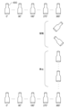
- the acquisition unit 241 holds the container 400 in an upright posture using the gripping device 110 so that its central axis is parallel to the direction of gravity. At this time, the rotation angle of the container 400 around the central axis is set to 0° as shown in FIG.
- the acquisition unit 241 uses the gripping device 110 to rotate the container 400 in one direction from 0° to 360° around its central axis at a constant rotational speed, as shown in FIG.
- the device 130 continuously photographs the liquid near the bottom of the container 400. As a result, images of the vicinity of the bottom surface of the container 400 are obtained at each predetermined angle.
- the image group obtained at this time is called a first image group.
- the acquisition unit 241 uses the gripping device 110 to swing and tilt the container 400, as shown in FIG. 10, and then makes it stand still in an upright state for a certain period of time.
- the liquid in the container 400 flows, and foreign matter with a light specific gravity is made to float in the liquid.
- foreign objects such as metal pieces with large specific gravity only move along the bottom surface of the container 400 even during rocking, and do not necessarily float.
- the acquisition unit 241 uses the gripping device 110 to reversely rotate the container 400 from 360° toward 0° about its central axis at a constant rotation speed, while the camera device 130 Then, the liquid near the bottom of the container 400 is continuously photographed again. As a result, images of the vicinity of the bottom surface of the container 400 are obtained at each predetermined angle.
- the image group obtained at this time is called a second image group.
- the detection unit 242 acquires a difference image between each image included in the second image group acquired by the acquisition unit 241 and an image included in the first image group captured at the same angle, and calculates the difference image. Based on this, foreign matter present on the bottom surface of the container 400 is detected. For example, a scratch on the container 400 on the bottom surface of the container 400 is shown at the same position in the two images taken at the same angle, and therefore does not appear in the difference image. On the other hand, since the foreign matter present on the bottom of the container moves from its original position to another position due to the rocking of the container 400, a shadow appears in the difference image. The acquisition unit 241 detects a shadow appearing in the difference image as a foreign object.
- the detection unit 242 acquires the shape, brightness distribution, size, etc. of the foreign object from the shadow image (image patch) that appears in the difference image. Further, the detection unit 242 calculates a movement trajectory of the foreign object indicating the relative movement of the foreign object with respect to the container 400 from the time series of the difference images. Then, the detection unit 242 determines the type of foreign object based on at least one of the shape, brightness distribution, size, and movement trajectory of the foreign object. For example, the detection unit 242 determines that the object is a piece of glass if there is a large difference in brightness within the shadow area, and determines that it is a piece of metal if there is little difference in brightness.
- the display control unit 243 is configured to display the presence or absence of a foreign object detected on the bottom surface of the container 400 and the type of foreign object on the screen of the display device 300.
- the period of rocking shown in FIG. 10 is a period in which the acquisition unit 241 rocks and tilts the container 400 for a certain period of time, similar to step S1 in FIG.
- the stationary period shown in FIG. 10 is a period during which the acquisition unit 241 continuously photographs the stationary container 400 with the camera device 130, as in step S2 of FIG.
- the types of foreign objects are classified by their materials, such as hair pieces/fiber pieces, plastic pieces, rubber pieces, glass pieces, metal pieces, etc.
- the types of foreign objects may be defined by other than the material. For example, based on the specific gravity of the liquid in the container 400, it may be classified into buoyant foreign objects whose specific gravity is lighter than the liquid, sedimentary foreign objects whose specific gravity is heavier than the liquid, and floating foreign objects whose specific gravity is similar to that of the liquid. .
- the foreign object inspection device 1 includes a detection means 2 and a display control means 3.
- the detection means 2 is configured to detect foreign substances present in the liquid and their types from a plurality of images obtained by successively photographing a container filled with liquid.
- the detection means 2 can be configured in the same manner as the detection unit 242 in FIG. 2, for example, but is not limited thereto.
- the display control means 3 is configured to output the type of foreign object detected by the detection means 2 to the display device.
- the display control means 3 can be configured in the same manner as the display control section 243 in FIG. 2, for example, but is not limited thereto.
- the foreign matter inspection device 1 configured as above functions as follows. That is, the detection means 2 detects the foreign matter present in the liquid and its type from a plurality of images obtained by successively photographing a container containing the liquid. Next, the display control means 3 outputs the type of foreign object detected by the detection means 2 to the display device.
- the type of detected foreign object is displayed on the screen of the display device, so that the type of foreign object can be recognized.
- the present invention can be used in the field of detecting foreign substances and their types in liquids such as medicines and pharmaceuticals sealed in containers.
- the display control means further outputs the moving trajectory image of the foreign object to the display device as a still image.
- the display control means further outputs to the possession device an index indicating a location on which the foreign object is detected in the movement trajectory image.
- Foreign matter inspection device according to appendix 2.
- the display control means further outputs the moving trajectory image of the foreign object to the display device as a moving image when the index is specified.
- the display control means further outputs information regarding the cause of the contamination of the foreign matter to the display device.
- the display control means further outputs the type of foreign matter floating in the liquid in the container to the display device.
- the display control means further outputs the type of foreign matter present on the bottom surface of the container to the display device.
- Inspection system 110 Gripping device 120 Lighting device 130 Camera device 200 Inspection device 300 Display device 400 Container 401 Rubber stopper
Landscapes
- Physics & Mathematics (AREA)
- Health & Medical Sciences (AREA)
- Life Sciences & Earth Sciences (AREA)
- Chemical & Material Sciences (AREA)
- Analytical Chemistry (AREA)
- Biochemistry (AREA)
- General Health & Medical Sciences (AREA)
- General Physics & Mathematics (AREA)
- Immunology (AREA)
- Pathology (AREA)
- Image Processing (AREA)
Abstract
異物検査装置は、検知手段と表示制御手段とを備える。検知手段は、液体が封入された容器を連続して撮影して得られた複数の画像から液体中に存在する異物とその種類を検知する。表示制御手段は、検知された異物の種類を表示装置に出力する。
Description
本発明は、異物検査装置、異物検査方法、および、記録媒体に関する。
容器に封入された液体中の異物の有無を検査する装置が提案されている。
例えば、特許文献1では、容器中の液体をカメラで連続して撮影して得られた複数の画像から浮遊物の移動軌跡を算出し、その移動軌跡の特徴に基づいて浮遊物が気泡および異物の何れであるかを判定し、その判定結果を表示装置の画面に表示する。
しかしながら、容器中の液体に異物が検知された場合に、異物の種類を認識するのは困難であった。ところで、生産ラインで生産された容器中の液体に異物が検知された場合、同様の事象が繰り返されないように生産ラインを早急に改善する必要がある。しかしながら、ありとあらゆるものが、ありとあらゆる場所で混入する可能性があるため、混入した異物の種類が分からなければ混入経路の特定が難しい。
本発明は、上述した課題を解決する異物検査装置を提供することにある。
本発明の一形態に係る異物検査装置は、
液体が封入された容器を連続して撮影して得られた複数の画像から前記液体中に存在する異物とその種類を検知する検知手段と、
前記検知された異物の種類を表示装置に出力する表示制御手段と、
を備えるように構成されている。
液体が封入された容器を連続して撮影して得られた複数の画像から前記液体中に存在する異物とその種類を検知する検知手段と、
前記検知された異物の種類を表示装置に出力する表示制御手段と、
を備えるように構成されている。
本発明の他の形態に係る異物検査方法は、
液体が封入された容器を連続して撮影して得られた複数の画像から前記液体中に存在する異物とその種類を検知し、
前記検知された異物の種類を表示装置に出力する、
ように構成されている。
液体が封入された容器を連続して撮影して得られた複数の画像から前記液体中に存在する異物とその種類を検知し、
前記検知された異物の種類を表示装置に出力する、
ように構成されている。
本発明の他の形態に係るコンピュータ読み取り可能な記録媒体は、
コンピュータに、
液体が封入された容器を連続して撮影して得られた複数の画像から前記液体中に存在する異物とその種類を検知する処理と、
前記検知された異物の種類を表示装置に出力する処理と、
を行わせるプログラムを記録するように構成されている。
コンピュータに、
液体が封入された容器を連続して撮影して得られた複数の画像から前記液体中に存在する異物とその種類を検知する処理と、
前記検知された異物の種類を表示装置に出力する処理と、
を行わせるプログラムを記録するように構成されている。
本発明は、上述したような構成を有することにより、検知された異物の種類が表示装置に出力されるため、異物の種類を認識することができる。
次に、本発明の実施の形態について、図面を参照して詳細に説明する。
[第1の実施の形態]
図1は、本発明の第1の実施形態に係る検査システム100のブロック図である。図1を参照すると、検査システム100は、容器400に封入された液体中の異物の有無を検査するシステムである。検査システム100は、主な構成要素として、把持装置110と、照明装置120と、カメラ装置130と、検査装置200と、表示装置300と、を備えている。
[第1の実施の形態]
図1は、本発明の第1の実施形態に係る検査システム100のブロック図である。図1を参照すると、検査システム100は、容器400に封入された液体中の異物の有無を検査するシステムである。検査システム100は、主な構成要素として、把持装置110と、照明装置120と、カメラ装置130と、検査装置200と、表示装置300と、を備えている。
容器400は、ガラス瓶やペットボトルなどの透明または半透明な容器である。容器400の内部には、薬剤や水などの液体が封入・充填されている。また、容器400に封入された液体中には、異物が混入している可能性がある。異物としては、例えば、ガラス片、プラスチック片、ゴム片、毛髪片・繊維片、金属片、などが想定される。
把持装置110は、容器400を所定の姿勢で把持するように構成されている。所定の姿勢は任意である。例えば、容器400が正立しているときの姿勢を所定の姿勢としてよい。あるいは、容器400が正立した姿勢から所定の角度で傾いた姿勢を所定の姿勢としてよい。以下では、容器400が正立した姿勢を所定の姿勢として説明する。容器400を正立した姿勢で把持する機構は、任意である。例えば、把持する機構は、容器400を正立した姿勢で載置する台座と、台座上に載置された容器400の頭頂部であるゴム栓401の上面部を押圧する部材などを含んで構成されていてよい。
また、把持装置110は、容器400を把持した状態で、容器400を正立した姿勢から所定方向に回転させ、傾斜させ、または揺動させるように構成されている。容器400を回転・傾斜・揺動させる機構は、任意である。例えば、回転・傾斜・揺動させる機構は、把持機構全体を、容器400を把持した状態で回転・傾斜・揺動させるモータを含んで構成されていてよい。
また、把持装置110は、有線または無線により検査装置200と接続されている。把持装置110は、検査装置200からの指示により起動されると、容器400を把持した状態で、容器400を正立した姿勢から所定方向に回転・傾斜・揺動させる。また、把持装置110は、検査装置200からの指示により停止されると、容器400を回転・傾斜・揺動させる動作を停止し、容器400を正立した姿勢で把持する状態に復帰する。
上記のように容器400を回転・傾斜・揺動させると、容器400の内側底面などに付着していた異物が底面を移動し、および/または浮遊する状態が得られる。同時に、容器400の内側壁面などに付着していた気泡や液体の流動の過程で混ざり込んだ気泡が液体中を浮遊する可能性がある。このような状態は容器400を静止させた後でも液体が慣性により流動している期間中は継続する。従って、検査装置200は、浮遊物が異物であるか、気泡であるかを識別する必要がある。
照明装置120は、容器400に封入された液体に対して照明光を照射するように構成されている。照明装置120は、例えば、容器400の大きさに応じたサイズの面光源である。照明装置120は、容器400からみてカメラ装置130が設置される側とは反対側に設置されている。すなわち、照明装置120による照明は、透過照明である。ただし、照明装置120の位置はこれに限定せず、例えば容器400の底面側やカメラ装置130に隣接する位置に設置して、反射光照明として撮影する形態をとってもよい。
カメラ装置130は、容器400からみて照明装置120が設置される側とは反対側の所定位置から、容器400内の液体を、所定の高フレームレートで連続して撮影する高速撮影装置である。カメラ装置130は、例えば、数百万画素程度の画素容量を有するCCD(Charge-Coupled Device)イメージセンサやCMOS(Complementary MOS)イメージセンサを備えたカラーカメラまたは白黒カメラを含んで構成されていてよい。カメラ装置130は、有線または無線により、検査装置200と接続されている。カメラ装置130は、撮影して得られた時系列の画像を、撮影時刻を示す情報などと共に、検査装置200に対して送信するように構成されている。
表示装置300は、LCD(Liquid Crystal Display:液晶ディスプレイ)などの表示装置である。表示装置300は、検査装置200と有線または無線により接続されている。表示装置300は、検査装置200で行われた容器400の検査結果などを表示するように構成されている。
検査装置200は、カメラ装置130によって撮影して得られた時系列の画像に対して画像処理を行って、容器400に封入された液体中の異物の有無および異物の種類を検査する情報処理装置である。検査装置200は、把持装置110、カメラ装置130、および表示装置300と有線または無線により接続されている。
図2は、検査装置200の一例を示すブロック図である。図2を参照すると、検査装置200は、通信I/F部210と操作入力部220と記憶部230と演算処理部240とを備えている。
通信I/F部210は、データ通信回路から構成され、有線または無線により把持装置110、カメラ装置130、表示装置300、および図示しない他の外部装置との間でデータ通信を行うように構成されている。操作入力部220は、キーボードやマウスなどの操作入力装置から構成され、オペレータの操作を検出して演算処理部240に出力するように構成されている。
記憶部230は、ハードディスクやメモリなどの1種類あるいは多種類の1以上の記憶装置から構成され、演算処理部240における各種処理に必要な処理情報およびプログラム231を記憶するように構成されている。プログラム231は、演算処理部240に読み込まれて実行されることにより各種処理部を実現するプログラムであり、通信I/F部210などのデータ入出力機能を介して図示しない外部装置や記録媒体から予め読み込まれて記憶部230に保存される。記憶部230に記憶される主な処理情報には、画像情報232、追跡情報233、検査結果情報234、および、異物混入要因情報236がある。
画像情報232は、容器400内の液体をカメラ装置130によって連続して撮影して得られた時系列の画像を含んでいる。容器400内の液体中に浮遊物が存在する場合、画像情報232には、浮遊物の像が写っている。
図3は、画像情報232の構成例を示す。この例の画像情報232は、容器ID2321と撮影時刻2322とフレーム画像2323との組からなるエントリから構成されている。容器ID2321の項目には、容器400を一意に識別するIDが設定される。容器ID2321としては、容器400に振られた通し番号、容器400に貼付されたバーコード、容器400のゴム栓401などから採取された物体指紋情報などが考えられる。撮影時刻2322およびフレーム画像2323の各項目には、撮影時刻およびフレーム画像が設定される。撮影時刻2322は、同じ容器IDの他のフレーム画像と区別して識別できるような精度(例えばミリ秒単位)に設定されている。撮影時刻2322は、例えば、容器400の回転・傾斜・揺動を停止した時点からの経過時間を用いてよい。図3の例では、フレーム画像2323毎に容器ID2321を関連付けているが、複数のフレーム画像2323のグループ毎に容器ID2321を関連付けるようにしてもよい。
追跡情報233は、容器400内の液体中に存在する浮遊物の像を検出して追跡した浮遊物の移動軌跡を表す時系列データを含んでいる。図4は、追跡情報233の構成例を示す。この例の追跡情報233は、容器ID2331、追跡ID2332とポインタ2333との組、の各エントリから構成されている。容器ID2331のエントリには、容器400を一意に識別するIDが設定される。追跡ID2332とポインタ2333との組からなるエントリは、追跡対象の浮遊物毎に設けられる。追跡ID2332の項目には、追跡対象の浮遊物を同じ容器400内の他の浮遊物と識別するためのIDが設定される。ポインタ2333の項目には、追跡対象とする浮遊物の移動軌跡情報2334へのポインタが設定される。
移動軌跡情報2334は、時刻23341と位置情報23342とサイズ23343と輝度分布23344と形状23345との組からなるエントリから構成されている。時刻23341と位置情報23342とサイズ23343と輝度分布23344と形状23345との項目には、撮影時刻とその撮影時刻における追跡対象の浮遊物の位置を示す座標値と浮遊物のサイズと浮遊物領域内の輝度分布と浮遊物の形状とが設定される。時刻23341に設定する撮影時刻は、フレーム画像の撮影時刻2322を用いる。座標値は、例えば、予め定められた座標系における座標値であってよい。また、予め定められた座標系は、カメラを中心としてみたカメラ座標系であってもよいし、実空間中のある位置を中心として考えたワールド座標系であってもよい。移動軌跡情報2334のエントリは、時刻23341の順に並べられている。先頭のエントリの時刻23341は、追跡開始時刻である。最後尾のエントリの時刻23341は、追跡終了時刻である。先頭および最後尾以外のエントリの時刻23341は、追跡中間時刻である。
検査結果情報234は、容器400の検査の結果に応じた情報を含んでいる。図5は、検査結果情報234の構成例を示す。この例の検査結果情報234は、容器ID2341、検査結果2342、異物検出数2343、気泡検出数2344、検出異物ID2345とポインタ2346との組、検出気泡ID2347とポインタ2348との組、の各エントリから構成されている。容器ID2341のエントリには、検査対象の容器400を一意に識別するIDが設定される。検査結果2342のエントリには、OK(検査合格)またはNG(検査不合格)の何れかの検査結果が設定される。異物検出数2343のエントリには、検出された異物の総数および/または種類毎の異物の総数が設定される。気泡検出数2344のエントリには、検出された気泡の総数が設定される。
検出異物ID2345とポインタ2346との組のエントリは、検出された異物毎に設けられる。検出異物ID2345の項目には、検出された異物を同じ容器400内の他の異物と識別するためのIDが設定される。ポインタ2346の項目には、検出された異物の検出異物情報2349へのポインタが設定される。
検出気泡ID2347とポインタ2348との組のエントリは、検出された気泡毎に設けられる。検出気泡ID2347の項目には、検出された気泡を同じ容器400内の他の気泡と識別するためのIDが設定される。ポインタ2348の項目には、検出された気泡の検出気泡情報2350へのポインタが設定される。
検出異物情報2349は、追跡ID23491とポインタ23492との組、異物種類23493、移動軌跡静止画23494、移動軌跡動画23495、の各エントリから構成されている。追跡ID23491の項目には、検出された異物の追跡ID2332が設定される。ポインタ23492の項目には、検出された異物の移動軌跡情報2334へのポインタが設定される。異物種類23493のエントリには、判定された異物の種類が設定される。異物種類23493のエントリには、異物の種類に加えて、判定結果の確率がさらに設定されていてよい。判定結果の確率は、判定結果の確からしさを表す指標である。
移動軌跡静止画23494のエントリには、検出された異物の移動軌跡情報2334を可視化した静止画が少なくとも1枚設定される。図6は、移動軌跡静止画23494の例を示す模式図である。この例の移動軌跡静止画23494は、背景画像234941と移動軌跡画像234942とを重ね合わせた合成画像である。
背景画像234941は、例えば、検出された異物が気泡でなく特定の種類の異物として判定された最も信頼度の高いフレーム画像を使用してよい。但し、背景画像234941は、上記以外のフレーム画像、例えば、検出された異物が写っている任意のフレーム画像を使用してもよい。
移動軌跡画像234942は、異物の移動軌跡を表す線を含んで構成される。図6の例では、破線を使用しているが、実線であってもよい。また、移動軌跡画像234942は、異物の移動方向を表す矢印が付加されている。但し、異物の移動方向を表す態様は、矢印に限定されない。例えば、異物の移動軌跡を表す線の線種、幅、色などを移動時間の経過に応じて変化させるようにして異物の移動方法を表してもよい。更に、移動軌跡画像234942は、異物の移動速度に応じて表示形態を変えてもよい。例えば、異物の移動速度に応じて、線の線種、幅、色などを変化させるようにして異物の移動速度を表してもよい。
また、移動軌跡静止画23494には、異物の種類を表示する表示欄234943が描画されている。表示欄234943には、異物種類23493に設定された異物の種類が、例えばテキストで表示される。さらに、移動軌跡静止画23494には、異物の判定根拠となる箇所を示す指標234944が描画されている。図6では、指標234944は、判定根拠となる箇所を囲む矩形であるが、それに限定されない。異物の判定根拠となる箇所とは、当該異物が気泡でなく、特定の種類の異物であると判定された移動軌跡情報の箇所を意味する。例えば、ステンレス片などの金属片は比重が大きいため液体の動きの影響が少なく、ほぼ直線的に落下する移動軌跡が得られる。そのため、直線的に落下している箇所が、金属片であると判定された根拠となる箇所になる。また、ゴム片など金属片に比較して比重の小さい異物では、追跡開始時刻における位置より低い位置まで沈降した箇所が、判定根拠となる箇所になり得る。
再び図5を参照すると、移動軌跡動画23495のエントリには、検出された異物の移動軌跡情報2334を可視化した動画が設定される。
検出気泡情報2350は、追跡ID23501とポインタ23502との組、判定結果23503、移動軌跡静止画23504、移動軌跡動画23505の各エントリから構成されている。追跡ID23501の項目には、検出された気泡の追跡ID2332が設定される。ポインタ23502の項目には、検出された気泡の移動軌跡情報2334へのポインタが設定される。判定結果23503のエントリには、判定結果が「気泡」である旨のテキストが設定される。判定結果23503のエントリには、判定結果の確率がさらに設定されていてよい。
移動軌跡静止画23504のエントリには、検出された気泡の移動軌跡情報2334を可視化した静止画が少なくとも1枚設定される。移動軌跡動画23505のエントリには、検出された気泡の移動軌跡情報2334を可視化した動画が設定される。
再び図2を参照すると、異物混入要因情報236は、容器400に異物が混入した要因に関する情報を含んでいる。図7は、異物混入要因情報236の一例を示す。この例では、異物混入要因情報236は、複数のエントリ2361から構成され、それぞれのエントリ2361は異物の種類23611と要因23612との組から構成される。異物の種類23611の項目には、例えば、毛髪片・繊維片、プラスチック片、ゴム片、ガラス片、金属片が設定されている。また、要因23612には、例えば、毛髪片・繊維片に対応して「人」、プラスチック片およびガラス片に対応して「容器」、ゴム片に対応して「容器栓」、金属片に対応して「製造機器」が、それぞれ設定されている。これは、例えば、金属片は製造機器に由来する異物であることを表している。
演算処理部240は、MPUなどのマイクロプロセッサとその周辺回路を有し、記憶部230からプログラム231を読み込んで実行することにより、上記ハードウェアとプログラム231とを協働させて各種処理部を実現するように構成されている。演算処理部240で実現される主な処理部には、取得部241、検知部242、および表示制御部243がある。
取得部241は、把持装置110およびカメラ装置130を制御して、容器400に封入された液体中に存在する浮遊物の像を写した画像情報232を取得するように構成されている。また、取得部241は、画像情報232を解析することにより、浮遊物の移動軌跡を表す時系列データを含む追跡情報233を取得するように構成されている。
検知部242は、取得部241によって取得された追跡情報233に基づいて、容器400の液体に異物が存在するか否かを検知し、さらに存在した異物の種類を検知するように構成されている。また、検知部242は、検知結果に基づいて検査結果情報234を作成し、記憶部230に保存するように構成されている。
表示制御部243は、検知部242によって検査結果情報234が作成されると、可及的速やかに検査結果情報234を表示装置300に出力するように構成されている。
次に、本実施形態に係る検査システム100の全体的な動作を説明する。
図8は、1つの容器400に対する検査開始から検査終了までの検査システム100の動作の一例を示すフローチャートである。図8を参照すると、先ず、取得部241は、容器400内の液体の流動を誘発させる(ステップS1)。例えば、取得部241は、把持装置110により容器400を回転・傾斜・揺動させた後に正立した姿勢で静止させる。次に、取得部241は、照明装置120による透過照明の下で、カメラ装置130により容器400内の液体を連続して撮像することにより、所定のフレームレートで所定の時間長にわたった撮像された時系列の画像を取得する(ステップS2)。取得部241によりカメラ装置130から取得された時系列の画像は、画像情報232として、記憶部230に保存される。図3に例示したように、画像情報232は、容器ID2321と撮影時刻2322とフレーム画像2323との組からなるエントリから構成されている。
次に、検知部242は、画像情報232に含まれる時系列の画像の中で、液体中に存在する浮遊物を検出する(ステップS3)。次に、検知部242は、画像情報232に含まれる時系列の画像の中で、上記検出した浮遊物を追跡する(ステップS4)。検知部242は、追跡された浮遊物それぞれの追跡結果を、追跡情報233として、記憶部230に保存する。図4に例示したように、追跡情報233は、追跡対象とする浮遊物毎の移動軌跡情報2334を含んでいる。また、移動軌跡情報2334の複数のエントリは時刻23341の順に並べられ、それぞれのエントリは、追跡対象の浮遊物の位置情報23342、サイズ23343、輝度分布23344、および形状23345を有する。
次に、検知部242は、追跡情報233に含まれる追跡ID2332で特定される浮遊物毎に、浮遊物の移動軌跡情報2334に基づいて、浮遊物が異物であるか気泡であるかを判定し、さらに異物である浮遊物はその種別を判定する(ステップS5)。次に、検知部242は、浮遊物それぞれの判定結果を記録した検査結果情報234を作成し、記憶部230に保存する(ステップS6)。検査結果情報234は、図5に例示したように、容器ID2341、検査結果2342、異物検出数2343、気泡検出数2344、検出された異物毎の検出異物情報2349、検出された気泡毎の検出気泡情報2350を含んでいる。また、検出異物情報2349は、異物種類23493、移動軌跡静止画23494、移動軌跡動画23495などを含んでいる。また、検出気泡情報2350は、判定結果(気泡)23503、移動軌跡静止画23504、移動軌跡動画23505などを含んでいる。
次に、表示制御部243は、容器400の検査結果情報234を表示装置300に出力する(ステップS7)。
続いて、取得部241と検知部242と表示制御部243について詳細に説明する。
先ず、取得部241の詳細を説明する。
取得部241は、先ず、容器400を正立した姿勢で把持している把持装置110を起動することにより、検査対象の容器400を回転・傾斜・揺動させる。次に、取得部241は、起動後、一定時間が経過すると、把持装置110を停止させることにより、容器400を所定の姿勢で静止させる。このように容器400を一定時間にわたって傾斜・揺動・回転させた後に静止させることにより、静止した容器400内で液体が慣性によって流動する状態が得られる。次に、取得部241は、照明装置120による透過照明の下で、容器400内の液体をカメラ装置130によって所定のフレームレートで連続して撮影する動作を開始する。即ち、取得部241は、容器400が回転・傾斜・揺動された後に静止した時刻を時刻Tsとすると、時刻Tsから上記撮影動作を開始する。
また、取得部241は、時刻Tsから所定時間Twが経過する時刻Teまで、容器400内の液体をカメラ装置130によって連続して撮影し続ける。上記所定時間Twは、例えば、液体中を浮遊する浮遊物が全て気泡であると仮定した場合に、全ての気泡が容器400の上方に向かって移動し、もはや下方に移動するとは考えられないような移動軌跡が得られるのに必要な時間(以下、最小撮影時間長と記す)以上に設定されていてよい。最小撮影時間長は、予め実験などによって決定され、取得部241に固定的に設定されていてよい。なお、取得部241は、時刻Teに達したときに、カメラ装置130による撮影を直ちに停止してもよいし、なおもカメラ装置130による撮影を続けてもよい。
取得部241は、カメラ装置130から取得した時系列のフレーム画像のそれぞれに、撮影時刻および容器IDを付加し、画像情報232として記憶部230に保存する。
次に取得部241は、所定時間長分の時系列のフレーム画像が取得されると、それらのフレーム画像のそれぞれから、容器400内の液体中の浮遊物の陰影を検出する。例えば、取得部241は、以下に記載するような方法によって液体中の浮遊物の陰影を検出する。但し、取得部241は、以下に記載した以外の方法によって液体中の浮遊物の陰影を検出してよい。
先ず、取得部241は、フレーム画像のそれぞれに対して2値化処理を行って、2値化フレーム画像を作成する。次に、取得部241は、2値化フレーム画像のそれぞれから、以下のようにして浮遊物の陰影を検出する。
取得部241は、先ず、浮遊物の陰影を検出する対象とする2値化フレーム画像を注目中2値化フレーム画像とする。次に、注目中2値化フレーム画像と、撮影時刻がΔtだけ後の2値化フレーム画像との差分画像を生成する。ここで、Δtは、2つの画像において同じ浮遊物が一部分で重なるか、重ならない場合でもごく近接した位置に現れる程度の時間に設定される。そのため、時間差Δtは、液体および異物の性質や流動状態などに応じて定められる。上記差分画像では、2つの2値化フレーム画像で一致する画像部分は消去され、相違する画像部分だけが残される。このため、2つの2値化フレーム画像の同じ位置に現れる容器400の輪郭や傷などは消去され、浮遊物の陰影だけが現れる。取得部241は、差分画像で陰影が現れた箇所に対応する注目中2値化フレーム画像の陰影を、注目中2値化フレーム画像中に存在する浮遊物の陰影として検出する。
取得部241は、検出された浮遊物を時系列の画像の中で追跡し、追跡の結果に応じて追跡情報233を作成する。先ず、取得部241は、追跡情報233を初期化する。この初期化では、図4の容器ID2331のエントリに容器400の容器IDが設定される。次に、取得部241は、以下に記載するような方法によって、時系列の画像の中で、浮遊物を追跡し、その追跡結果に応じて、浮遊物毎に、図4の追跡ID2332とポインタ2333との組のエントリ、移動軌跡情報2334を作成する。
先ず、取得部241は、上記作成した2値化フレーム画像の時系列のうち、撮影時刻が最も過去の2値化フレーム画像に注目する。次に、取得部241は、注目中2値化フレーム画像において検出された浮遊物それぞれに、一意となる追跡IDを付与する。次に、取得部241は、検出された浮遊物毎に、注目中2値化フレーム画像において検出された浮遊物に付与した追跡IDを、図4の追跡ID2332の項目に設定し、対応するポインタ2333で指示される移動軌跡情報2334の先頭エントリの時刻23341の項目に注目中2値化フレーム画像の撮影時刻を設定し、位置情報23342とサイズ23343と輝度分布23344と形状23345との項目に注目中2値化フレーム画像における浮遊物の座標値とサイズと輝度分布と形状とを設定する。
次に、取得部241は、注目中2値化フレーム画像より1フレームだけ後の2値化フレーム画像に注目を移す。次に、取得部241は、注目中2値化フレーム画像において検出された浮遊物の1つに注目する。次に、取得部241は、注目中浮遊物の位置と、1フレームだけ前の2値化フレーム画像(以下、先行2値化フレーム画像と記す)において検出された浮遊物の位置とを比較し、注目中浮遊物から予め定められた閾値距離以内に浮遊物が存在すれば、注目中浮遊物と当該閾値距離以内に存在した浮遊物とは同一の浮遊物であると判定する。この場合、取得部241は、注目中の浮遊物に、同一の浮遊物と判定した浮遊物に対して付与されている追跡IDを付与する。そして、取得部241は、付与した追跡ID2332が設定されている追跡情報233のエントリのポインタ2333が指し示す移動軌跡情報2334に新たなエントリを確保し、その確保したエントリの時刻23341と位置情報23342とサイズ23343と輝度分布23344と形状23345とに、注目中2値化フレーム画像の撮影時刻と注目中浮遊物の座標値とサイズと輝度分布と形状とを設定する。
一方、取得部241は、先行2値化フレーム画像において注目中浮遊物から閾値距離以内に浮遊物が存在しない場合、注目中浮遊物は新規な浮遊物と判定し、新たな追跡IDを付与する。次に、取得部241は、注目中浮遊物に付与した追跡IDを、新たに確保したエントリの図4の追跡ID2332の項目に設定し、対応するポインタ2333で指示される移動軌跡情報2334の先頭エントリの時刻23341の項目に注目中2値化フレーム画像の撮影時刻を設定し、位置情報23342とサイズ23343と輝度分布23344と形状23345との項目に注目中浮遊物の座標値とサイズと輝度分布と形状とを設定する。
取得部241は、注目中浮遊物についての処理を終えると、注目中2値化フレーム画像において検出された次の浮遊物に注目を移し、前述した処理と同様の処理を繰り返す。そして、取得部241は、注目中2値化フレーム画像において検出された全ての浮遊物について注目し終えると、1フレームだけ後のフレーム画像に注目を移し、上述した処理と同様の処理を繰り返す。そして、取得部241は、画像情報232における最後のフレーム画像まで注目し終えると、追跡処理を終了する。
以上の説明では、取得部241は、隣接する2つのフレーム画像における浮遊物間の距離に基づいて追跡を行った。しかし、取得部241は、nフレーム(nは1以上の正の整数)を挟んで隣接する2つのフレーム画像における浮遊物間の距離に基づいて追跡を行うようにしてもよい。また、取得部241は、mフレーム(mは0以上の正の整数)を挟んで隣接する2つのフレーム画像における浮遊物間の距離に基づいて追跡を行った追跡結果と、m+jフレーム(jは1以上の正の整数)を挟んで隣接する2つのフレーム画像における浮遊物間の距離に基づいて追跡を行った追跡結果とを総合的に判断して追跡を行うようにしてもよい。
次に、検知部242の詳細を説明する。
検知部242は、記憶部230から追跡情報233を読み出し、追跡情報233に含まれる浮遊物の移動軌跡情報2334毎に、その移動軌跡情報2334に基づいて、浮遊物の種類(クラス)を識別する。識別クラス数は、例えば、気泡クラス、毛髪片・繊維片クラス、プラスチック片クラス、ゴム片クラス、ガラス片クラス、金属片クラス、その他クラスの合計7クラスとすることができるが、それに限定されず、2クラス以上であれば任意である。例えば、検知部242は、浮遊物の移動軌跡情報2334から認識される、浮遊物の移動軌跡の特徴および浮遊物の外観の特徴(形状、輝度分布、サイズ)が、気泡と異物とで相違し、また異物の種類によって相違することを利用して、それぞれの浮遊物のクラスを識別する。
例えば、気泡と異物とでは、移動軌跡の特徴に以下のような相違がある。液体に比べて圧倒的に比重が小さな気泡は、液体中を反重力方向に移動する傾向が強く表れる。これに対して、気泡に対して比重の大きな異物は、液体中を反重力方向に移動する傾向は強くなく、その傾向は比重がより大きくなる異物ほど顕著になる。例えば、毛髪片・繊維片は、液体との比重の差が大きくないため、液中を漂う傾向がある。プラスチック片は、気泡ほどではないが液体に比べて比重が小さいので、液面付近を浮遊しやすい。ゴム片、ガラス片、金属片は、液体より比重が大きいため、底面付近に浮遊ないし位置する傾向がある。
また、気泡と異物とでは、外観の特徴に以下のような相違がある。気泡は、リング状やドーナツ状などの中抜け形状を有する傾向があるが、異物にはそのような傾向はない。また、毛髪片・繊維片は、細長い形状が多い。ガラス片は、検知領域(浮遊物領域)内で輝度差が大きい傾向があるのに対して、金属片は検知領域内で輝度差はほとんどない。
検知部242が浮遊物の移動軌跡情報2334に基づいて、浮遊物のクラスを識別する具体的な方法は、各種考えられる。例えば、検知部242は、浮遊物の移動軌跡情報から浮遊物のクラスを推定するための機械学習を行った学習済みの学習モデルに浮遊物の移動軌跡情報2334を入力し、当該浮遊物の識別クラスと識別スコアを当該学習モデルから取得し、識別スコア最大の識別クラスを当該浮遊物の識別クラスに決定するように構成されていてよい。学習モデルは、例えば、浮遊物の移動軌跡情報とその浮遊物のクラスを表す正解ラベルとのペアを教師データとしてニューラルネットワークなどの機械学習アルゴリズムを用いた機械学習によって、事前に生成することができる。但し、検知部242が浮遊物の移動軌跡情報2334に基づいて浮遊物のクラスを識別する方法は上記に限定されず、ルールベースによるモデルを使用してもよい。
検知部242は、浮遊物の移動軌跡情報2334毎の判定結果に応じた検査結果情報234を作成し、記憶部230に保存する。例えば、検知部242は、先ず、初期化された検査結果情報234を記憶部230に作成し、その検査結果情報234の容器ID2341のエントリに、追跡情報233の容器ID2331を設定する。次に、検知部242は、異物と判定された浮遊物の総数を計数し、その計数値が0であれば、検査結果情報234の検査結果2342のエントリにOK(検査合格)を設定し、異物検出数2343のエントリに値0を設定する。また、検知部242は、異物と判定された浮遊物の総数が1以上であれば、検査結果情報234の検査結果2342のエントリにNG(検査不合格)を設定し、異物検出数2343のエントリに異物と判定された浮遊物の総数を設定する。次に、検知部242は、気泡であると判定された浮遊物の総数を計数し、その計数値を検査結果情報234の気泡検出数2344のエントリに設定する。
次に、検知部242は、異物であると判定された浮遊物毎に、検出異物ID2345とポインタ2346の組のエントリと、そのポインタ2346で指示される検出異物情報2349とを検査結果情報234に作成する。また、検知部242は、検出異物ID2345の項目には、容器ID2341で識別される検査対象の容器400から検出された異物を他の異物と区別するための通し番号などのIDを設定する。また、検知部242は、検出異物情報2349における追跡ID23491の項目には、異物であると判定された浮遊物に対して追跡情報233で付与された追跡ID2332を設定する。また、検知部242は、ポインタ23492の項目には、移動軌跡情報2334へのポインタを設定する。また、検知部242は、異物種類23493のエントリには、判定された異物の種類を設定する。また、検知部242は、移動軌跡静止画23494のエントリには、検出された異物の移動軌跡情報2334を可視化した静止画を設定する。また、検知部242は、移動軌跡動画23495のエントリには、検出された異物の移動軌跡情報2334を可視化した動画を設定する。
次に、検知部242は、気泡であると判定された浮遊物毎に、検出気泡ID2347とポインタ2348の組のエントリと、そのポインタ2348で指示される検出気泡情報2350とを検査結果情報234に作成する。また、検知部242は、検出気泡ID2347の項目には、容器ID2341で識別される検査対象の容器400から検出された気泡を他の気泡と区別するための通し番号などのIDを設定する。また、検知部242は、検出気泡情報2350における追跡ID23501の項目には、気泡であると判定された浮遊物に対して追跡情報233で付与された追跡ID2332を設定する。また、検知部242は、ポインタ23502の項目には、移動軌跡情報2334へのポインタを設定する。また、検知部242は、判定結果(気泡)23503のエントリには、気泡である旨のテキストを設定する。また、検知部242は、移動軌跡静止画23504のエントリには、移動軌跡情報2334を可視化した静止画を設定する。また、検知部242は、移動軌跡動画23505のエントリには、移動軌跡情報2334を可視化した動画を設定する。
次に、表示制御部243を詳細に説明する。
表示制御部243は、検査結果情報234を表示装置300に出力する制御を行う。表示制御部243は、検知部242によって検査対象の容器400に対する検査結果情報234が作成され次第、検査結果情報234を記憶部230から読み出す。次に、表示制御部243は、読み出した検査結果情報234に基づいて、検査結果表示画面を作成する。次に、表示制御部243は、作成した検査結果表示画面を表示装置300に表示させる。
図9は、表示装置300に表示される検査結果表示画面1000の例を示す。この例では、表示制御部243は、検査結果表示画面上に、進行状況インジケータ1001、異物有無インジケータ1002、累計インジケータ1003、および、移動軌跡静止画1004を、それぞれ表示している。進行状況インジケータ1001は、検査装置200が、検査対象の容器400が検査装置200に搬入された状態、搬入された容器400が検査装置200で検査中の状態、検査装置200が検査を終えた容器400を搬出している状態の何れの状態であるかを表示する。異物有無インジケータ1002は、検査中の容器400で少なくとも1つの異物が検出されたか否かを表示する。累計インジケータ1003は、現時点までに検査を終えた全ての容器400のうち異物がなかった容器の総数と異物があった容器の総数を表示する。移動軌跡静止画1004は、図6を参照して説明した移動軌跡静止画を表示する。
また、表示制御部243は、検査結果表示画面1000の移動軌跡静止画1004に表示された異物の種類を表示する表示欄234943が操作入力部220を通じてオペレータからクリックなどで指定されると、表示欄234943に表示された異物の種類に対応して異物混入要因情報236に設定された要因を取得し、表示装置300の画面に表示する。これにより、検査装置200のオペレータ等は、異物混入の要因を即座に認識することができる。
さらに、表示制御部243は、検査結果表示画面1000の移動軌跡静止画1004に表示された異物の判定根拠となる箇所を示す指標234944が操作入力部220を通じてオペレータからクリックなどで指定されると、この移動軌跡静止画1004を保持する検出異物情報2349の移動軌跡動画23495を記憶部230から読み出し、この読み出した移動軌跡動画23495を再生して表示装置300の画面に表示する。このとき、表示制御部243は、上記移動軌跡動画23495だけを再生して表示してもよいし、同じ容器400から検出された全ての異物の移動軌跡の動画を合成して表示装置300の画面に表示してもよく、さらに同じ容器400から検出された全ての異物および気泡の移動軌跡の動画を合成して表示装置300の画面に表示してもよい。
以上説明したように、本実施形態によれば、検査装置200は、液体が封入された容器400を連続して撮影して得られた複数の画像から液体中に存在する異物とその種類を検知する検知部242と、検知された異物の種類を表示装置300に表示する表示制御部243とを備えている。このため、検査装置200のオペレータなどは、容器400の液体中に異物が混入していたことに加えて、その異物の種類を直ちに認識することができる。そのため、異物の種類が表示されない場合に比較して、異物混入経路の特定が容易かつ迅速に行える。
続いて、本実施形態の変形例について説明する。
<変形例1>
上記実施形態では、取得部241は、把持装置110により容器400を回転・傾斜・揺動させた後に正立した姿勢で静止させ、静止させた状態の容器400内の液体をカメラ装置130により連続して撮像することにより画像情報232を取得した。しかし、比重の大きい金属片などの異物は、容器400を揺動させても底面に沿って移動する程度で浮遊しないことがある。また、容器400を静止させると、底面を移動していた金属片はその動きを止めるため、容器の傷と見做されて検知されないことがある。そのため、取得部241は、把持装置110により容器400を回転させている最中に、容器400内の底面付近の液体をカメラ装置130により連続して撮影することにより画像情報232を取得するように構成されていてよい。また、検知部242は、容器400の回転中に取得された連続する複数の画像に基づいて、容器400の底面に沿って移動する異物を検知するようにしてよい。また、表示制御部243は、容器400の底面において検知された異物の移動軌跡および画像パッチならびに異物の種類を表示装置300の画面に表示させるようにしてよい。以下、その詳細について説明する。
上記実施形態では、取得部241は、把持装置110により容器400を回転・傾斜・揺動させた後に正立した姿勢で静止させ、静止させた状態の容器400内の液体をカメラ装置130により連続して撮像することにより画像情報232を取得した。しかし、比重の大きい金属片などの異物は、容器400を揺動させても底面に沿って移動する程度で浮遊しないことがある。また、容器400を静止させると、底面を移動していた金属片はその動きを止めるため、容器の傷と見做されて検知されないことがある。そのため、取得部241は、把持装置110により容器400を回転させている最中に、容器400内の底面付近の液体をカメラ装置130により連続して撮影することにより画像情報232を取得するように構成されていてよい。また、検知部242は、容器400の回転中に取得された連続する複数の画像に基づいて、容器400の底面に沿って移動する異物を検知するようにしてよい。また、表示制御部243は、容器400の底面において検知された異物の移動軌跡および画像パッチならびに異物の種類を表示装置300の画面に表示させるようにしてよい。以下、その詳細について説明する。
先ず、取得部241は、把持装置110により容器400をその中心軸が重力方向と平行になるように正立した姿勢で保持する。このときの容器400の中心軸まわりの回転角を図10に示すように0°とする。次に、取得部241は、把持装置110により、図10に示すように、容器400をその中心軸を中心に一定の回転速度で0°から360°に向かって一方向に回転させながら、カメラ装置130で容器400の底面付近の液体を連続して撮影する。これにより、所定角度毎に、容器400の底面付近を撮影した画像が得られる。このとき得られた画像群を第1の画像群と呼ぶ。
次に、取得部241は、把持装置110により、図10に示すように、容器400を揺動・傾斜させ、その後に一定期間にわたって正立した状態で静止させる。これにより、容器400内の液体が流動し、それに応じて比重の軽い異物は液体中を浮遊する状態が得られる。しかし、比重の大きな金属片などの異物は、揺動中でも容器400の底面に沿って移動するだけで必ずしも浮遊しない。
次に、取得部241は、把持装置110により、図10に示すように、容器400をその中心軸を中心に一定の回転速度で360°から0°に向かって逆回転させながら、カメラ装置130で容器400の底面付近の液体を再び連続して撮影する。これにより、所定角度毎に、容器400の底面付近を撮影した画像が得られる。このとき得られた画像群を第2の画像群と呼ぶ。
検知部242は、取得部241によって取得された第2の画像群に含まれる各画像と、同じ角度で撮影された第1の画像群に含まれる画像との差分画像を取得し、その差分画像に基づいて、容器400の底面に存在する異物を検出する。例えば、容器400の底面に存在する容器の傷などは、同じ角度で撮影された2枚の画像で同じ位置に写っているため、差分画像には現れない。一方、容器底面に存在する異物は、容器400の揺動によって元の位置から別の位置へ移動するため、差分画像に陰影が現れる。取得部241は、差分画像に現れた陰影を異物として検知する。
また、検知部242は、差分画像に現れた陰影の画像(画像パッチ)から異物の形状、輝度分布、サイズなどを取得する。さらに、検知部242は、差分画像の時系列から容器400に対する異物の相対的な動きを示す異物の移動軌跡を算出する。そして、検知部242は、異物の形状、輝度分布、サイズ、移動軌跡の少なくとも1つから、異物の種類を判定する。例えば、検知部242は、陰影領域内で輝度差が大きければガラス片であると判定し、輝度差がほとんどなければ金属片であると判定する。
そして、表示制御部243は、容器400の底面において検知された異物の有無および異物の種類を表示装置300の画面に表示するように構成されている。
<変形例2>
上記実施形態と上記変形例1とを併せもつ実施形態としてもよい。即ち、図10に示した揺動の期間は、取得部241が図8のステップS1と同様に容器400を一定期間だけ揺動、傾斜させる期間とする。また、図10に示した静止期間は、取得部241が図8のステップS2と同様に静止した容器400をカメラ装置130で連続して撮影する期間とする。
上記実施形態と上記変形例1とを併せもつ実施形態としてもよい。即ち、図10に示した揺動の期間は、取得部241が図8のステップS1と同様に容器400を一定期間だけ揺動、傾斜させる期間とする。また、図10に示した静止期間は、取得部241が図8のステップS2と同様に静止した容器400をカメラ装置130で連続して撮影する期間とする。
<変形例3>
上記実施形態では、異物の種類を、毛髪片・繊維片、プラスチック片、ゴム片、ガラス片、金属片などのように材質で分類したが、材質以外で異物の種類を定義してもよい。例えば、容器400内の液体の比重を基準にして、液体よりも比重の軽い浮上性異物、液体より比重の重い沈降性異物、液体と同程度の比重を持つ浮遊性異物に分類してもよい。
上記実施形態では、異物の種類を、毛髪片・繊維片、プラスチック片、ゴム片、ガラス片、金属片などのように材質で分類したが、材質以外で異物の種類を定義してもよい。例えば、容器400内の液体の比重を基準にして、液体よりも比重の軽い浮上性異物、液体より比重の重い沈降性異物、液体と同程度の比重を持つ浮遊性異物に分類してもよい。
[第2の実施の形態]
次に、本発明の第2の実施形態について、図11を参照して説明する。
次に、本発明の第2の実施形態について、図11を参照して説明する。
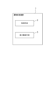
図11を参照すると、本実施形態に係る異物検査装置1は、検知手段2と表示制御手段3とを備える。
検知手段2は、液体が封入された容器を連続して撮影して得られた複数の画像から液体中に存在する異物とその種類を検知するように構成されている。検知手段2は、例えば、図2の検知部242と同様に構成することができるが、それに限定されない。
表示制御手段3は、検知手段2によって検知された異物の種類を表示装置に出力するように構成されている。表示制御手段3は、例えば、図2の表示制御部243と同様に構成することができるが、それに限定されない。
以上のように構成された異物検査装置1は、以下のように機能する。即ち、検知手段2は、液体が封入された容器を連続して撮影して得られた複数の画像から液体中に存在する異物とその種類を検知する。次に、表示制御手段3は、検知手段2によって検知された異物の種類を表示装置に出力する。
以上のように構成され動作する異物検査装置によれば、検知された異物の種類が表示装置の画面に表示されるため、異物の種類を認識することができる。
以上、上記各実施形態を参照して本発明を説明したが、本発明は、上述した実施形態に限定されるものではない。本発明の構成や詳細には、本発明の範囲内で当業者が理解しうる様々な変更をすることができる。
本発明は、容器に封入された薬剤や医薬品などの液体中の異物とその種類を検出する分野に利用できる。
上記の実施形態の一部又は全部は、以下の付記のようにも記載され得るが、以下には限られない。
[付記1]
液体が封入された容器を連続して撮影して得られた複数の画像から前記液体中に存在する異物とその種類を検知する検知手段と、
前記検知された異物の種類を表示装置に出力する表示制御手段と、
を備える異物検査装置。
[付記2]
前記表示制御手段は、さらに、前記異物の移動軌跡画像を静止画で前記表示装置に出力する、
付記1に記載の異物検査装置。
[付記3]
前記表示制御手段は、さらに、前記移動軌跡画像における前記異物の検知根拠となる箇所を示す指標を前記憑依装置に出力する、
付記2に記載の異物検査装置。
[付記4]
前記表示制御手段は、さらに、前記指標が指定された場合、前記異物の移動軌跡画像を動画で前記表示装置に出力する、
付記3に記載の異物検査装置。
[付記5]
前記表示制御手段は、さらに、前記異物が混入した要因に関する情報を前記表示装置に出力する、
付記1乃至4の何れかに記載の異物検査装置。
[付記6]
前記表示制御手段は、さらに、前記容器の液体中を浮遊する異物の種類を前記表示装置に出力する、
付記1乃至5の何れかに記載の異物検査装置。
[付記7]
前記表示制御手段は、さらに、前記容器の底面に存在する異物の種類を前記表示装置に出力する、
付記1乃至6の何れかに記載の異物検査装置。
[付記8]
液体が封入された容器を連続して撮影して得られた複数の画像から前記液体中に存在する異物とその種類を検知し、
前記検知された異物の種類を表示装置に出力する、
異物検査方法。
[付記9]
前記表示では、さらに、前記異物の移動軌跡画像を静止画で前記表示装置に出力する、
付記8に記載の異物検査方法。
[付記10]
前記表示では、さらに、前記移動軌跡画像における前記異物の検知根拠となる箇所を示す指標を前記表示装置に出力する、
付記9に記載の異物検査方法。
[付記11]
前記表示では、さらに、前記指標が指定された場合、前記異物の移動軌跡画像を動画で前記表示装置に出力する、
付記10に記載の異物検査方法。
[付記12]
前記表示では、さらに、前記異物が混入した要因に関する情報を前記表示装置に出力する、
付記8乃至11の何れかに記載の異物検査方法。
[付記13]
前記表示では、さらに、前記容器の液体中を浮遊する異物の種類を前記表示装置に出力する、
付記8乃至12の何れかに記載の異物検査方法。
[付記14]
前記表示では、さらに、前記容器の底面に存在する異物の種類を前記表示装置に出力する、
付記8乃至13の何れかに記載の異物検査方法。
[付記15]
コンピュータに、
液体が封入された容器を連続して撮影して得られた複数の画像から前記液体中に存在する異物とその種類を検知する処理と、
前記検知された異物の種類を表示装置に出力する処理と、
を行わせるためのプログラムを記録したコンピュータ読み取り可能な記録媒体。
100 検査システム
110 把持装置
120 照明装置
130 カメラ装置
200 検査装置
300 表示装置
400 容器
401 ゴム栓
110 把持装置
120 照明装置
130 カメラ装置
200 検査装置
300 表示装置
400 容器
401 ゴム栓
Claims (15)
- 液体が封入された容器を連続して撮影して得られた複数の画像から前記液体中に存在する異物とその種類を検知する検知手段と、
前記検知された異物の種類を表示装置に出力する表示制御手段と、
を備える異物検査装置。 - 前記表示制御手段は、さらに、前記異物の移動軌跡画像を静止画で前記表示装置に出力する、
請求項1に記載の異物検査装置。 - 前記表示制御手段は、さらに、前記移動軌跡画像における前記異物の検知根拠となる箇所を示す指標を前記表示装置に出力する、
請求項2に記載の異物検査装置。 - 前記表示制御手段は、さらに、前記指標が指定された場合、前記異物の移動軌跡画像を動画で前記表示装置に出力する、
請求項3に記載の異物検査装置。 - 前記表示制御手段は、さらに、前記異物が混入した要因に関する情報を前記表示装置に出力する、
請求項1乃至4の何れかに記載の異物検査装置。 - 前記表示制御手段は、さらに、前記容器の液体中を浮遊する異物の種類を前記表示装置に出力する、
請求項1乃至5の何れかに記載の異物検査装置。 - 前記表示制御手段は、さらに、前記容器の底面に存在する異物の種類を前記表示装置に出力する、
請求項1乃至6の何れかに記載の異物検査装置。 - 液体が封入された容器を連続して撮影して得られた複数の画像から前記液体中に存在する異物とその種類を検知し、
前記検知された異物の種類を表示装置に出力する、
異物検査方法。 - 前記表示では、さらに、前記異物の移動軌跡画像を静止画で前記表示装置に出力する、
請求項8に記載の異物検査方法。 - 前記表示では、さらに、前記移動軌跡画像における前記異物の検知根拠となる箇所を示す指標を前記表示装置に出力する、
請求項9に記載の異物検査方法。 - 前記表示では、さらに、前記指標が指定された場合、前記異物の移動軌跡画像を動画で前記表示装置に出力する、
請求項10に記載の異物検査方法。 - 前記表示では、さらに、前記異物が混入した要因に関する情報を前記表示装置に出力する、
請求項8乃至11の何れかに記載の異物検査方法。 - 前記表示では、さらに、前記容器の液体中を浮遊する異物の種類を前記表示装置に出力する、
請求項8乃至12の何れかに記載の異物検査方法。 - 前記表示では、さらに、前記容器の底面に存在する異物の種類を前記表示装置に出力する、
請求項8乃至13の何れかに記載の異物検査方法。 - コンピュータに、
液体が封入された容器を連続して撮影して得られた複数の画像から前記液体中に存在する異物とその種類を検知する処理と、
前記検知された異物の種類を表示装置に出力する処理と、
を行わせるためのプログラムを記録したコンピュータ読み取り可能な記録媒体。
Priority Applications (1)
| Application Number | Priority Date | Filing Date | Title |
|---|---|---|---|
| PCT/JP2022/012744 WO2023175943A1 (ja) | 2022-03-18 | 2022-03-18 | 異物検査装置 |
Applications Claiming Priority (1)
| Application Number | Priority Date | Filing Date | Title |
|---|---|---|---|
| PCT/JP2022/012744 WO2023175943A1 (ja) | 2022-03-18 | 2022-03-18 | 異物検査装置 |
Publications (1)
| Publication Number | Publication Date |
|---|---|
| WO2023175943A1 true WO2023175943A1 (ja) | 2023-09-21 |
Family
ID=88022975
Family Applications (1)
| Application Number | Title | Priority Date | Filing Date |
|---|---|---|---|
| PCT/JP2022/012744 WO2023175943A1 (ja) | 2022-03-18 | 2022-03-18 | 異物検査装置 |
Country Status (1)
| Country | Link |
|---|---|
| WO (1) | WO2023175943A1 (ja) |
Citations (4)
| Publication number | Priority date | Publication date | Assignee | Title |
|---|---|---|---|---|
| CN103743755A (zh) * | 2013-12-20 | 2014-04-23 | 许雪梅 | 一种基于近邻传播聚类的医用药剂中可见异物检测方法 |
| CN109709108A (zh) * | 2019-02-26 | 2019-05-03 | 天津迦自机器人科技有限公司 | 一种瓶装透明液体杂质检测设备及方法 |
| JP2019174346A (ja) * | 2018-03-29 | 2019-10-10 | 富士通株式会社 | 検査方法、検査装置、及び検査プログラム |
| WO2021214994A1 (ja) * | 2020-04-24 | 2021-10-28 | 日本電気株式会社 | 検査システム |
-
2022
- 2022-03-18 WO PCT/JP2022/012744 patent/WO2023175943A1/ja unknown
Patent Citations (4)
| Publication number | Priority date | Publication date | Assignee | Title |
|---|---|---|---|---|
| CN103743755A (zh) * | 2013-12-20 | 2014-04-23 | 许雪梅 | 一种基于近邻传播聚类的医用药剂中可见异物检测方法 |
| JP2019174346A (ja) * | 2018-03-29 | 2019-10-10 | 富士通株式会社 | 検査方法、検査装置、及び検査プログラム |
| CN109709108A (zh) * | 2019-02-26 | 2019-05-03 | 天津迦自机器人科技有限公司 | 一种瓶装透明液体杂质检测设备及方法 |
| WO2021214994A1 (ja) * | 2020-04-24 | 2021-10-28 | 日本電気株式会社 | 検査システム |
Similar Documents
| Publication | Publication Date | Title |
|---|---|---|
| JP7216146B2 (ja) | 流体中の非溶解粒子の非破壊的検出のための方法および装置 | |
| JP7359297B2 (ja) | 検査システム | |
| US10746665B2 (en) | Methods and apparatus for classifying an artifact in a specimen | |
| CA2976769C (en) | Model-based methods and apparatus for classifying an interferent in specimens | |
| NO309213B1 (no) | Fremgangsmåte og apparat for inspeksjon av væskefylte beholdere | |
| US20100220919A1 (en) | Method and installation for detecting foreign bodies inside a container | |
| JPS5937451A (ja) | 対象物の透明度のコントラストにより対象物を検査する方法及び装置 | |
| JP2004354100A (ja) | 容器内液体中の異物検出方法及びその装置 | |
| JP7234502B2 (ja) | 方法、装置、及びプログラム | |
| JP4517826B2 (ja) | 液面検出方法 | |
| KR101440302B1 (ko) | 유리병 검사장치 | |
| JP5635963B2 (ja) | 飲料液異物検査装置および飲料液異物検査方法 | |
| JP2001116703A (ja) | 容器内浮遊物判別方法及びその装置 | |
| WO2023175943A1 (ja) | 異物検査装置 | |
| JP2004257937A (ja) | 異物検査装置および検査方法 | |
| WO2022244075A1 (ja) | 検査システム | |
| WO2023047542A1 (ja) | 学習装置 | |
| WO2023105724A1 (ja) | 異物検査装置 | |
| WO2024079857A1 (ja) | 検査システム | |
| WO2024079858A1 (ja) | 検査システム | |
| JPH0275941A (ja) | 検びん装置 | |
| WO2024176360A1 (ja) | 情報処理装置 | |
| FR2493989A1 (fr) | Procede et appareil de detection de defauts dans des bouteilles en verre en utilisant des proximites d'evenements | |
| WO2021214820A1 (ja) | 把持装置 | |
| JPH0196540A (ja) | 液体中の異物検出方法 |
Legal Events
| Date | Code | Title | Description |
|---|---|---|---|
| 121 | Ep: the epo has been informed by wipo that ep was designated in this application |
Ref document number: 22932213 Country of ref document: EP Kind code of ref document: A1 |