WO2023175751A1 - 制御装置、制御方法およびプログラム - Google Patents
制御装置、制御方法およびプログラム Download PDFInfo
- Publication number
- WO2023175751A1 WO2023175751A1 PCT/JP2022/011760 JP2022011760W WO2023175751A1 WO 2023175751 A1 WO2023175751 A1 WO 2023175751A1 JP 2022011760 W JP2022011760 W JP 2022011760W WO 2023175751 A1 WO2023175751 A1 WO 2023175751A1
- Authority
- WO
- WIPO (PCT)
- Prior art keywords
- sampling data
- rotation angle
- period
- control device
- recorded
- Prior art date
- Legal status (The legal status is an assumption and is not a legal conclusion. Google has not performed a legal analysis and makes no representation as to the accuracy of the status listed.)
- Ceased
Links
Images




Classifications
-
- B—PERFORMING OPERATIONS; TRANSPORTING
- B25—HAND TOOLS; PORTABLE POWER-DRIVEN TOOLS; MANIPULATORS
- B25J—MANIPULATORS; CHAMBERS PROVIDED WITH MANIPULATION DEVICES
- B25J9/00—Program-controlled manipulators
- B25J9/16—Program controls
- B25J9/1615—Program controls characterised by special kind of manipulator, e.g. planar, scara, gantry, cantilever, space, closed chain, passive/active joints and tendon driven manipulators
-
- B—PERFORMING OPERATIONS; TRANSPORTING
- B25—HAND TOOLS; PORTABLE POWER-DRIVEN TOOLS; MANIPULATORS
- B25J—MANIPULATORS; CHAMBERS PROVIDED WITH MANIPULATION DEVICES
- B25J13/00—Controls for manipulators
- B25J13/08—Controls for manipulators by means of sensing devices, e.g. viewing or touching devices
-
- B—PERFORMING OPERATIONS; TRANSPORTING
- B25—HAND TOOLS; PORTABLE POWER-DRIVEN TOOLS; MANIPULATORS
- B25J—MANIPULATORS; CHAMBERS PROVIDED WITH MANIPULATION DEVICES
- B25J13/00—Controls for manipulators
- B25J13/08—Controls for manipulators by means of sensing devices, e.g. viewing or touching devices
- B25J13/088—Controls for manipulators by means of sensing devices, e.g. viewing or touching devices with position, velocity or acceleration sensors
-
- B—PERFORMING OPERATIONS; TRANSPORTING
- B25—HAND TOOLS; PORTABLE POWER-DRIVEN TOOLS; MANIPULATORS
- B25J—MANIPULATORS; CHAMBERS PROVIDED WITH MANIPULATION DEVICES
- B25J19/00—Accessories fitted to manipulators, e.g. for monitoring, for viewing; Safety devices combined with or specially adapted for use in connection with manipulators
- B25J19/02—Sensing devices
- B25J19/027—Electromagnetic sensing devices
-
- B—PERFORMING OPERATIONS; TRANSPORTING
- B25—HAND TOOLS; PORTABLE POWER-DRIVEN TOOLS; MANIPULATORS
- B25J—MANIPULATORS; CHAMBERS PROVIDED WITH MANIPULATION DEVICES
- B25J5/00—Manipulators mounted on wheels or on carriages
-
- B—PERFORMING OPERATIONS; TRANSPORTING
- B25—HAND TOOLS; PORTABLE POWER-DRIVEN TOOLS; MANIPULATORS
- B25J—MANIPULATORS; CHAMBERS PROVIDED WITH MANIPULATION DEVICES
- B25J9/00—Program-controlled manipulators
- B25J9/16—Program controls
- B25J9/1694—Program controls characterised by use of sensors other than normal servo-feedback from position, speed or acceleration sensors, perception control, multi-sensor controlled systems, sensor fusion
Definitions
- the present invention relates to a control device, a control method, and a program.
- Patent Document 1 discloses a detection value acquisition unit that acquires at least one detection value indicating the state of a moving body having a drive unit, and a detection value acquisition unit that selects at least a part of control parameters of the drive unit based on the at least one detection value.
- a control device is described that includes a control parameter selection unit that uses the selected control parameters and a drive control unit that determines a control input value for the drive unit using the selected control parameters.
- the rotation angle of the joint is detected by a rotation angle sensor such as an encoder attached to the joint, and the detected value is sent to a calculation device that performs calculations for controlling the robot.
- a rotation angle sensor such as an encoder attached to the joint
- potentiometers and magnetic sensors are also used as rotation angle sensors, but in either case, the accuracy of detected values may decrease due to environmental factors or changes over time.
- rotation angle sensors are attached to many joints, so for example, Improving the performance of rotation angle sensors is not easy from a cost perspective.
- the present invention provides a control device, a control method, and a control device that can improve the accuracy of the rotation angle value obtained based on the detected value of the rotation angle sensor without requiring higher performance of the rotation angle sensor itself.
- the purpose is to provide programs.
- a control device including a processor that executes an operation according to a program, wherein the operation is based on first sampling data in which a rotation angle of a joint is recorded in a first cycle.
- a control device comprising: generating second sampling data recorded in a second period in which the rotation angle is longer than the first period.
- the rotation angle of the joint portion is changed to the first sampling data based on the first sampling data recorded in the first cycle by the operation executed by the processor according to the program.
- a control method is provided that includes generating second sampling data recorded at a second period that is longer than the period.
- a program for causing a processor to execute an operation, wherein the operation is based on first sampling data in which the rotation angle of a joint is recorded in a first cycle.
- a program is provided that includes generating second sampling data recorded in a second period in which the rotation angle is longer than the first period.
- FIG. 1 is a diagram showing an example of a hardware configuration of a robot according to a first embodiment of the present invention.
- FIG. FIG. 2 is a block diagram showing an example of the configuration of a rotational drive section shown in FIG. 1.
- FIG. It is a sequence diagram which shows the example of operation
- FIG. 3 is a diagram conceptually illustrating the effects obtained by the operation of the processing circuit of the rotary drive unit in the first embodiment of the present invention.
- FIG. 3 is a diagram conceptually illustrating the effects obtained by the operation of the processing circuit of the rotary drive unit in the first embodiment of the present invention.
- 2 is a flowchart illustrating an example of processing when switching the sampling period in the first embodiment of the present invention. It is a sequence diagram which shows the example of operation
- 12 is a flowchart illustrating an example of processing when switching the sampling period in the second embodiment of the present invention. 12 is a flowchart illustrating an example of processing when only the operation on the arithmetic device side is switched in the second embodiment of the present invention.
- FIG. 1 is a diagram showing an example of the hardware configuration of a robot according to the first embodiment of the present invention.
- the robot 10 includes an arithmetic device 100 mounted on a main body 12 .
- the arithmetic device 100 includes a CPU (Central Processing Unit) 110, a RAM (Random Access Memory) 120, a ROM (Read Only Memory) 130, an external memory 140, and the like.
- the computing device 100 determines the operation of the robot 10 according to image data acquired by the camera 21, audio data acquired by the microphone 22, command signals received by the communication interface 24, and the like. Camera 21, microphone 22, and communication interface 24 are connected to computing device 100 via bus interface 150.
- the computing device 100 controls each part of the robot 10 so that the determined motion is executed.
- the arithmetic device 100 is provided at the joints of the arms 13L, 13R, hands 14L, 14R, legs 15L, 15R, and feet 16L, 16R so that the determined motion is executed.
- the rotation drive unit 30 is controlled by the rotation drive unit 30.
- the head 11 and the main body 12 may also be provided with a joint portion and a rotational drive portion 30.
- the calculation device 100 requires detection values of a distance measurement sensor (not shown), an inertial measurement unit (IMU) 25, a ground sensor 26, a load sensor (not shown), and a power supply control device 27. Please refer accordingly.
- the rotation drive unit 30, distance measurement sensor, IMU 25, ground sensor 26, load sensor, and power supply control device 27 are connected to the arithmetic device 100 via the bus interface 150.
- the CPU 110 selects a pattern corresponding to the determined motion from the control patterns stored in the ROM 130 or the external memory 140, thereby controlling the foot movement, ZMP (Zero Moment Point) trajectory, and body movement according to the pattern. Trunk motion, upper limb motion, waist horizontal position and height, etc. are set, and control signals are sent to the rotation drive unit 30 according to these set values.
- the calculation device 100 refers to the rotation angle data of the joint portion received from the rotation drive unit 30.
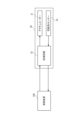
- FIG. 2 is a block diagram showing an example of the configuration of the rotation drive section shown in FIG. 1.
- the rotation drive unit 30 includes an actuator 31 that rotationally drives the joint, a rotation angle sensor 32 that detects the rotation angle of the joint, and a processing circuit 33.
- the processing circuit 33 is a control device implemented as firmware, for example, and executes predetermined operations according to a program written in a memory. Specifically, the processing circuit 33 drives the actuator 31 according to the control signal received from the arithmetic device 100, samples the detected value of the rotation angle sensor 32, and transmits it to the arithmetic device 100 as rotation angle data of the joint. .
- the rotation angle sensor 32 for example, a potentiometer, an optical encoder, a magnetic encoder, a magnetic sensor, a resolver, an inductive sensor, or an electrostatic sensor is used.
- the output of the rotation angle sensor 32 may be a continuous signal or a discrete signal.
- the processing circuit 33 may sample the detection value of the rotation angle sensor 32 by, for example, quantizing a continuous signal at a predetermined period, or may count a discrete signal at a predetermined period. In either case, the rotation angle of the joint is recorded in the sampling data at a predetermined period.
- the type of rotation angle sensor 32 in the embodiment of the present invention is not particularly limited, but a magnetic sensor is used as a non-limiting example.
- a magnetic sensor combines a permanent magnet with an element that converts a change in magnetic field into an electrical signal, such as a Hall element, AMR (Anisotropic Magneto Resistive) element, GMR (Giant Magneto Resistive) element, or TMR (Tunnel Magneto Resistance) element. It's a sensor. When the position of the permanent magnet attached to one member of the joint changes, the magnetic field distribution changes, and an element attached to the other member captures this change and converts it into an electrical signal, thereby detecting the rotation angle. be able to.
- TMR elements are preferably used because they have high output and high precision.
- FIG. 3 is a sequence diagram showing an example of the operation of the processing circuit of the rotational drive unit in the first embodiment of the present invention.
- the processing circuit 33 samples the detected value of the rotation angle sensor 32 at a period T1 (step S11). Furthermore, the processing circuit 33 transmits the rotation angle data to the arithmetic device 100 at a period T2 (step S13).
- the processing circuit 33 and the arithmetic device 100 are both devices built into the robot 10, but when the processing circuit 33 is viewed as one control device, the arithmetic device 100 corresponds to an external device.
- the period T2 in which the rotation angle data is transmitted is determined according to the communication period or bandwidth defined between the rotation drive unit 30 and the arithmetic device 100, and in the illustrated example, the period T2 is longer than the period T1. .
- the sampling rate of the detected value is 30 kHz
- the communication rate is 1 kHz.
- the data in which the rotation angle is recorded in the period T1, which is generated in step S11 above is also referred to as first sampling data
- the data in which the rotation angle is recorded in the period T2, which is transmitted in step S13. is also referred to as second sampling data.
- the processing circuit 33 executes a process of generating second sampling data in which rotation angles are recorded in a longer period T2, based on first sampling data in which rotation angles are recorded in a shorter period T1.
- this process is a process of calculating the rotation angle value of the second sampling data from a plurality of rotation angle values recorded as the first sampling data during the period T2 (step S12).
- the above process is a process of simply averaging, weighted averaging, or time-series smoothing of the values of the plurality of rotation angles recorded during the period T2.
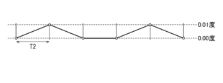
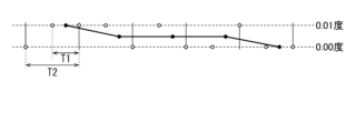
- FIGS. 4A and 4B are diagrams conceptually showing the effects obtained by the operation of the processing circuit of the rotational drive unit in the first embodiment of the present invention.
- FIG. 4A shows a case where the detection value of the rotation angle sensor 32 is sampled at the same period T2 as the communication.
- FIG. 4B the detection value of the rotation angle sensor 32 is sampled in a cycle T1 shorter than the communication cycle T2, and the two rotation angle values recorded in the cycle T1 are averaged to calculate the rotation angle in the cycle T2. This shows the case where the value of is calculated.
- the output rotation angle value is smoothed and the resolution of the rotation angle is higher.
- the resolution in the example of FIG. 4A, the rotation angle is detected in units of 0.01 degree, but in the example of FIG. 4B, the rotation angle is output in units of 0.005 degree.
- the rotation angle is changed between 0.00 degrees and 0.01 degrees, and the period T1 is simplified to be 1/2 of the period T2.
- the rotation angle may vary over a wider range, and the relationship between the periods T1 and T2 may be more complex.
- the period T1 may be smaller than 1/2 of the period T2 (in the above examples of 30 kHz and 1 kHz, the period T1 is 1/30 of the period T2), or the period T2 may be not an integral multiple of the period T1. It's okay.
- the method for calculating the second sampling data from the first sampling data is also appropriately selected, such as weighted averaging instead of simple averaging, time series smoothing (low-pass filtering), etc.
- a method may be used.
- the rotation drive section 30 samples the detected value of the rotation angle sensor 32 at a cycle shorter than the cycle of transmitting rotation angle data to the arithmetic device 100, and obtains the detected value by sampling. Sampling data matching the transmission period is generated from the multiple rotation angle values obtained. As a result, as described above, the value of the rotation angle can be smoothed and the resolution can be improved.
- Such a configuration has, for example, a restriction on the communication cycle between the rotary drive unit 30 and the arithmetic device 100 (for example, a restriction that the cycle cannot be shorter than the cycle T2), a restriction on the amount of communication (for example, a restriction that the cycle cannot be shorter than the cycle T2)
- a restriction on the communication cycle between the rotary drive unit 30 and the arithmetic device 100 for example, a restriction that the cycle cannot be shorter than the cycle T2
- a restriction on the amount of communication for example, a restriction that the cycle cannot be shorter than the cycle T2
- the magnetic sensor when using the magnetic sensor exemplified above as the rotation angle sensor 32, noise in the detected value may increase due to the influence of heat, the influence of external magnetism, aging, etc., or noise may increase due to changes in the actual rotation angle. There is a possibility that fluctuations in detected values may occur.
- the magnetic sensor can be used as the rotation angle sensor 32 in various external environments and for a long period of time while compensating for the influence of a decrease in the accuracy of the detected value.
- the arithmetic device 100 may be able to read the rotation angle with sufficient accuracy by using the results of sampling the detected values at the period T1). In such a case, the cost of the robot 10 can be reduced by using relatively inexpensive and low-precision sensors.
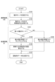
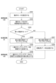
- FIG. 5 is a flowchart illustrating an example of processing when switching the sampling period in the first embodiment of the present invention.
- the arithmetic device 100 sets an operation mode (step S101), and transmits a control signal indicating the operation mode to the rotation drive unit 30 (step S102).
- the processing circuit 33 of the rotation drive unit 30 samples the detected value of the rotation angle sensor 32 at the cycle T1 (step S103), as described above. S104) to generate the first sampling data, and calculate the rotation angle value of the period T2 from the plurality of rotation angle values recorded as the first sampling data (step S105) to generate the second sampling data. generate.
- the processing circuit 33 samples the detected value of the rotation angle sensor 32 at the cycle T2 (step S106), thereby obtaining the second sampling data. generate. In either case, the processing circuit 33 transmits the generated second sampling data as rotation angle data to the arithmetic device 100 at a period T2 (step S107).
- the above configuration can be used, for example, when the accuracy of the rotation angle value required in the arithmetic device 100 varies depending on the operating state of the robot 10.
- the arithmetic device 100 switches between the first operation mode and the second operation mode according to the operation state of the robot 10. Specifically, in step S101 described above, the calculation device 100 sets a first operation mode in which a highly accurate rotation angle value can be obtained when the robot 10 is operating any of the joints.
- a second operation mode may be set in which the accuracy of the rotation angle value is low, but the power consumption of the rotation drive unit 30 including the processing circuit 33 can be reduced.
- the computing device 100 may determine the situation in which the robot 10 is placed by referring to the detection results of the camera 21, the microphone 22, the IMU 25, the ground sensor 26, etc., and set the operation mode according to the situation. . Specifically, the arithmetic device 100 sets the first operation mode when it is determined that the robot 10 is moving on rough ground based on the detection results of the camera 21, the ground sensor 26, etc., and sets the first operation mode in other cases. A second operating mode may also be set. For example, the computing device 100 may set one of the above operation modes for the entire robot 10, or may set the operation modes separately for parts including moving joints and other parts. good.
- the arithmetic device 100 may The operation mode may be fixedly set depending on the location of the joint. Specifically, lower body joints such as the legs 15L, 15R and feet 16L, 16R of the robot 10 are set to a first operation mode in which highly accurate rotation angle values can be obtained for walking. For joints of the upper body such as the arms 13L and 13R and the hands 14L and 14R, a second operation mode may be set in which the accuracy of the rotation angle value is low but power consumption can be reduced.
- the fixedly set operation mode may be switched.
- FIG. 6 is a sequence diagram illustrating an example of the operation of the rotation drive unit and the arithmetic unit in the second embodiment of the present invention.
- the arithmetic device 100 calculates the rotation angle at a period T2 based on first sampling data in which the rotation angle is recorded at a period T1. It functions as a control device that generates recorded second sampling data. Note that the other configurations are the same as those in the first embodiment, so redundant detailed explanation will be omitted.
- the processing circuit 33 of the rotation drive unit 30 samples the detected value of the rotation angle sensor 32 at a period T1 (step S21). As a result, first sampling data in which the rotation angle is recorded at the period T1 is generated.
- the processing circuit 33 transmits a series of first sampling data generated after the previous transmission to the arithmetic device 100 at a period T2 (step S22). Similar to the first embodiment, the processing circuit 33 and the arithmetic device 100 are both devices built into the robot 10, but when the arithmetic device 100 is viewed as one control device, the processing circuit 33 is This corresponds to an external device.
- the period T2 in which the rotation angle data is transmitted is determined according to the communication period defined between the rotation drive unit 30 and the arithmetic device 100, and in the illustrated example, the period T2 is longer than the period T1. Note that in the case of the present embodiment, the bandwidth defined between the rotation drive unit 30 and the arithmetic device 100 is large enough to allow a series of first sampling data to be transmitted every cycle T2.
- the arithmetic device 100 that has received the series of first sampling data transmitted from the processing circuit 33 calculates the rotation angle value of the second sampling data from the rotation angle value of the received series of first sampling data. (Step S23). More specifically, this process may be similar to the process described as step S12 in FIG. 3 in the first embodiment described above.
- the arithmetic device 100 executes a predetermined process using the generated second sampling data (step S24).
- the predetermined process is, for example, a process of calculating setting values to be sent to the rotation drive unit 30 in order to operate each part of the robot 10 as described above, but is not limited to this example.
- the above steps S23 and S24 are repeated every time a series of first sampling data is received every cycle T2 (step S22).
- the operations performed by the processing circuit 33 of the rotation drive unit 30 in the first embodiment are performed by the arithmetic device 100.
- the value of the rotation angle detected by the rotation angle sensor 32 can be smoothed and the resolution can be increased.
- the accuracy of the rotation angle value used by 100 can be improved.
- FIG. 7 is a flowchart illustrating an example of processing when switching the sampling period in the second embodiment of the present invention.
- the arithmetic device 100 sets an operation mode (step S201), and transmits a control signal indicating the operation mode to the rotation drive unit 30 (step S202).
- the processing circuit 33 of the rotation drive unit 30 samples the detected value of the rotation angle sensor 32 at a cycle T1 (step S204) to obtain the first operation mode. Sampling data is generated, and a series of first sampling data is transmitted to the arithmetic device 100 at a period T2 (step S205).
- the arithmetic device 100 generates second sampling data by calculating the rotation angle value of the period T2 from the received series of first sampling data (step S206).
- the processing circuit 33 samples the detected value of the rotation angle sensor 32 at a cycle T2 (step S207), thereby obtaining the second sampling data.
- the generated second sampling data is transmitted as rotation angle data to the arithmetic device 100 at a period T2 (step S208). In this case, the arithmetic device 100 uses the received second sampling data as is.
- the above configuration is similar to the example described in the first embodiment with reference to FIG. Available for In the example of FIG. 7, in addition to being able to save power consumption of the rotary drive unit 30 including the processing circuit 33 by lengthening the sampling period in the second operation mode, the amount of calculation by the arithmetic unit 100 is reduced.
- calculation resources can be used for other processing executed by the calculation device 100.
- the operation mode may be set for the entire robot 10 or may be set individually for each part. Further, the operation mode may be dynamically switched or fixedly set.
- FIG. 8 is a flowchart illustrating an example of processing when only the operation on the arithmetic device side is switched in the second embodiment of the present invention.
- the computing device 100 sets the operating mode (step S301), but the operating mode is not transmitted to the processing circuit 33 of the rotational drive unit 30, and the processing circuit 33
- First sampling data is generated by sampling the detected value of the rotation angle sensor 32 at a period T1 (step S302), and a series of first sampling data is transmitted to the arithmetic device 100 at a period T2 (step S303).
- the set operation mode is the first operation mode (YES in step S304)
- the calculation device 100 calculates the value of the rotation angle of period T2 from the received series of first sampling data (step S305).
- step S306 Use as second sampling data.
- This process is a step in which second sampling data is generated based on the first sampling data series, in that rotation angle values of the series of first sampling data that are not extracted are discarded. This is different from the process in S305.
- the calculation resources can be used for other processing executed by the calculation device 100, for example.
- Arithmetic device 100 may set the same operation mode for the first sampling data received from all rotary drive units 30, or may set an operation mode for each part of rotation drive unit 30. Further, as in the other examples above, the operation mode may be dynamically switched or may be set fixedly.
- the period T2 in which the arithmetic device 100 receives the rotation angle data and the period T2 in which the rotation angle is recorded in the second sampling data are the same, but these periods may be different.
- the arithmetic device 100 may receive a series of first sampling data at a period T3 that is different from the period T2, and may generate second sampling data in which the rotation angle is recorded at a period T2.
- the cycle T3 in which the rotation angle data is transmitted is the communication cycle defined between the rotation drive section 30 and the computing device 100
- the cycle T2 in which the rotation angle data is recorded is, for example, the rotation angle in the computing device 100. is the minimum period with a time resolution of
- control device may operate as the control device in the above embodiment.
- the robot does not necessarily have to be a humanoid robot with arms and legs, and may be an industrial robot with only arms, for example.
- control device according to the embodiment of the present invention is not limited to controlling the joints of robots, but can also control the joints of various machines or devices other than robots.
Landscapes
- Engineering & Computer Science (AREA)
- Robotics (AREA)
- Mechanical Engineering (AREA)
- Human Computer Interaction (AREA)
- Physics & Mathematics (AREA)
- Electromagnetism (AREA)
- Health & Medical Sciences (AREA)
- General Health & Medical Sciences (AREA)
- Orthopedic Medicine & Surgery (AREA)
- Manipulator (AREA)
Abstract
Description
図1は、本発明の第1の実施形態に係るロボットのハードウェア構成例を示す図である。図示された例において、ロボット10は、本体部12に搭載される演算装置100を有する。演算装置100は、CPU(Central Processing Unit)110、RAM(Random Access Memory)120、ROM(Read Only Memory)130、および外部メモリ140などを含む。演算装置100は、カメラ21が取得した画像データ、マイクロフォン22が取得した音声データ、または通信インターフェース24が受信したコマンド信号などに応じてロボット10の動作を決定する。カメラ21、マイクロフォン22、および通信インターフェース24は、バスインターフェース150を介して演算装置100に接続される。
図6は、本発明の第2の実施形態における回転駆動部および演算装置の動作の例を示すシーケンス図である。本実施形態では、上記の第1の実施形態と同様に構成されるロボット10において、演算装置100が、回転角が周期T1で記録された第1のサンプリングデータに基づいて回転角が周期T2で記録された第2のサンプリングデータを生成する制御装置として機能する。なお、それ以外の構成については第1の実施形態と同様であるため、重複した詳細な説明は省略する。
Claims (13)
- プログラムに従って動作を実行するプロセッサを備える制御装置であって、前記動作は、
関節部の回転角が第1の周期で記録された第1のサンプリングデータに基づいて、前記回転角が前記第1の周期よりも長い第2の周期で記録された第2のサンプリングデータを生成することを含む制御装置。 - 前記第2のサンプリングデータを生成することは、前記第1のサンプリングデータにおいて前記第2の周期の間に記録された複数の回転角の値から前記第2のサンプリングデータの回転角の値を算出することを含む、請求項1に記載の制御装置。
- 前記第2のサンプリングデータの回転角の値を算出することは、前記複数の回転角の値を単純平均するか、加重平均するか、または時系列で平滑化することを含む、請求項2に記載の制御装置。
- 前記動作は、前記第2のサンプリングデータを前記第2の周期で外部装置に送信することをさらに含む、請求項1から請求項3のいずれか1項に記載の制御装置。
- 前記動作は、前記第2のサンプリングデータを用いて所定の処理を実行することをさらに含む、請求項1から請求項3のいずれか1項に記載の制御装置。
- 前記動作は、回転角センサーの検出値を前記第1の周期でサンプリングすることによって前記第1のサンプリングデータを生成し、前記第1のサンプリングデータに基づいて前記第2のサンプリングデータを生成する第1の動作モードと、前記回転角センサーの検出値を前記第2の周期でサンプリングすることによって前記第2のサンプリングデータを生成する第2の動作モードとを切り替えることをさらに含む、請求項1から請求項5のいずれか1項に記載の制御装置。
- 前記動作は、外部装置から前記第2の周期で一連の前記第1のサンプリングデータを受信することを含み、
前記第2のサンプリングデータを生成することは、前記一連の前記第1のサンプリングデータの回転角の値から1つの前記第2のサンプリングデータの回転角の値を算出することを含む、請求項1から請求項5のいずれか1項に記載の制御装置。 - 前記動作は、前記外部装置から受信された前記一連の前記第1のサンプリングデータから前記第2のサンプリングデータを生成する第1の動作モードと、前記外部装置から前記第2の周期で受信される回転角の値を前記第2のサンプリングデータとして利用する第2の動作モードとを切り替えることをさらに含む、請求項7に記載の制御装置。
- 前記動作は、前記外部装置から受信された前記一連の前記第1のサンプリングデータから前記第2のサンプリングデータを生成する第1の動作モードと、前記外部装置から受信された前記一連の前記第1のサンプリングデータの回転角の値のうちの1つを抽出して前記第2のサンプリングデータとして利用する第2の動作モードとを切り替えることをさらに含む、請求項7に記載の制御装置。
- 前記動作は、外部装置から前記第2の周期とは異なる第3の周期で一連の前記第1のサンプリングデータを受信することを含み、
前記第2のサンプリングデータを生成することは、前記一連の前記第1のサンプリングデータの回転角の値から1つの前記第2のサンプリングデータの回転角の値を算出することを含む、請求項1から請求項5のいずれか1項に記載の制御装置。 - 前記関節部は、ロボットの関節部であり、
前記第1の動作モードと前記第2の動作モードとは、前記ロボットの動作の状態に応じて切り替えられる、請求項6、請求項8または請求項9に記載の制御装置。 - プロセッサがプログラムに従って実行する動作によって、
関節部の回転角が第1の周期で記録された第1のサンプリングデータに基づいて、前記回転角が前記第1の周期よりも長い第2の周期で記録された第2のサンプリングデータを生成することを含む制御方法。 - プロセッサに動作を実行させるためのプログラムであって、前記動作は、
関節部の回転角が第1の周期で記録された第1のサンプリングデータに基づいて、前記回転角が前記第1の周期よりも長い第2の周期で記録された第2のサンプリングデータを生成することを含むプログラム。
Priority Applications (2)
| Application Number | Priority Date | Filing Date | Title |
|---|---|---|---|
| US18/841,739 US20250162142A1 (en) | 2022-03-16 | 2022-03-16 | Control apparatus, control method, and program |
| PCT/JP2022/011760 WO2023175751A1 (ja) | 2022-03-16 | 2022-03-16 | 制御装置、制御方法およびプログラム |
Applications Claiming Priority (1)
| Application Number | Priority Date | Filing Date | Title |
|---|---|---|---|
| PCT/JP2022/011760 WO2023175751A1 (ja) | 2022-03-16 | 2022-03-16 | 制御装置、制御方法およびプログラム |
Publications (1)
| Publication Number | Publication Date |
|---|---|
| WO2023175751A1 true WO2023175751A1 (ja) | 2023-09-21 |
Family
ID=88022508
Family Applications (1)
| Application Number | Title | Priority Date | Filing Date |
|---|---|---|---|
| PCT/JP2022/011760 Ceased WO2023175751A1 (ja) | 2022-03-16 | 2022-03-16 | 制御装置、制御方法およびプログラム |
Country Status (2)
| Country | Link |
|---|---|
| US (1) | US20250162142A1 (ja) |
| WO (1) | WO2023175751A1 (ja) |
Citations (2)
| Publication number | Priority date | Publication date | Assignee | Title |
|---|---|---|---|---|
| JP2006068871A (ja) * | 2004-09-03 | 2006-03-16 | Toyota Motor Corp | 脚式ロボットとその制御方法ならびに歩容データの作成装置と作成方法 |
| WO2021060121A1 (ja) * | 2019-09-26 | 2021-04-01 | 株式会社ソニー・インタラクティブエンタテインメント | 制御装置、制御方法およびプログラム |
Family Cites Families (10)
| Publication number | Priority date | Publication date | Assignee | Title |
|---|---|---|---|---|
| JP2708458B2 (ja) * | 1988-04-01 | 1998-02-04 | 株式会社豊田中央研究所 | 倣い制御ロボット |
| JP6623522B2 (ja) * | 2015-01-26 | 2019-12-25 | セイコーエプソン株式会社 | ロボット、ロボットシステムおよびサーバー |
| DE102017005194C5 (de) * | 2017-05-31 | 2022-05-19 | Kuka Deutschland Gmbh | Steuern einer Roboteranordnung |
| JP7092307B2 (ja) * | 2019-02-01 | 2022-06-28 | 三菱電機株式会社 | 作業判別装置および作業判別方法 |
| CN113646718B (zh) * | 2019-03-27 | 2024-04-30 | 日产自动车株式会社 | 异常探测装置及异常探测方法 |
| CN113661033B (zh) * | 2019-04-02 | 2024-08-27 | 优傲机器人公司 | 具有可在运行时适配的安全限值的机器人臂安全系统 |
| US11292519B2 (en) * | 2020-01-31 | 2022-04-05 | Nsk Ltd. | Calibration method for rotation angle calculation device, calibration device for rotation angle calculation device, rotation angle calculation device, motor control device, electric actuator product, and electric power steering device |
| US11768504B2 (en) * | 2020-06-10 | 2023-09-26 | AI Incorporated | Light weight and real time slam for robots |
| JP7634952B2 (ja) * | 2020-09-23 | 2025-02-25 | キヤノン株式会社 | 情報処理方法、情報処理装置、表示方法、表示装置、プログラム、記録媒体、物品の製造方法、学習用データの取得方法 |
| KR102669137B1 (ko) * | 2021-10-25 | 2024-05-23 | 아주대학교산학협력단 | 협동 로봇의 건전성 모니터링 방법 및 시스템 |
-
2022
- 2022-03-16 US US18/841,739 patent/US20250162142A1/en active Pending
- 2022-03-16 WO PCT/JP2022/011760 patent/WO2023175751A1/ja not_active Ceased
Patent Citations (2)
| Publication number | Priority date | Publication date | Assignee | Title |
|---|---|---|---|---|
| JP2006068871A (ja) * | 2004-09-03 | 2006-03-16 | Toyota Motor Corp | 脚式ロボットとその制御方法ならびに歩容データの作成装置と作成方法 |
| WO2021060121A1 (ja) * | 2019-09-26 | 2021-04-01 | 株式会社ソニー・インタラクティブエンタテインメント | 制御装置、制御方法およびプログラム |
Also Published As
| Publication number | Publication date |
|---|---|
| US20250162142A1 (en) | 2025-05-22 |
Similar Documents
| Publication | Publication Date | Title |
|---|---|---|
| JP7719155B2 (ja) | ロボットシステム、制御方法、物品の製造方法、制御プログラム、記録媒体 | |
| JP6314426B2 (ja) | ロボット制御装置およびロボット制御方法 | |
| US8918215B2 (en) | Telematic interface with control signal scaling based on force sensor feedback | |
| JP2011069816A (ja) | 回転絶対位置センサを較正するためのシステムおよび方法 | |
| WO2003036602A2 (en) | Method for reducing limit cycle oscillations in a haptic device | |
| WO2008010485A1 (fr) | Robot, et son procédé de commande | |
| CN108778434A (zh) | 用户输入设备中控制杆的机械中心校准 | |
| CN108748220A (zh) | 一种基于惯性测量单元的脚-机跟随控制方法及控制系统 | |
| US12179349B2 (en) | Motion data generation system, motion data generation method, and motion data generation program of robot | |
| JPH096537A (ja) | コンピュータの周辺デバイス | |
| KR101549107B1 (ko) | 발판 모듈을 이용하여 외부 장치와 연동되는 인터랙션 장치 | |
| JP2013146792A (ja) | ロボット制御装置、ロボットシステム、センサー情報処理装置及びロボット制御方法 | |
| JP3937108B2 (ja) | ロボットの制御方法およびロボット | |
| JP6410245B2 (ja) | 移動自在型デバイスの振動ベースの軌道計算 | |
| KR20050005995A (ko) | 2족 보행 이동 장치의 보행 제어 방법 | |
| KR20160016757A (ko) | 모션 플랫폼 구성 | |
| US20250162142A1 (en) | Control apparatus, control method, and program | |
| JPH10253359A (ja) | センサの信号処理方法及び信号処理装置 | |
| JP7799922B2 (ja) | 把持装置及び把持装置の制御方法 | |
| JP2000009492A5 (ja) | 2次元アブソリュート位置センサ、ロボットおよびロボットコントローラ | |
| KR102288886B1 (ko) | 착용식 로봇의 구동 제어 방법 및 시스템 | |
| US8836266B2 (en) | Small motor controller | |
| JP3748454B2 (ja) | 産業用ロボットの制御装置 | |
| CN110371170B (zh) | 智能助力装置、系统以及用于控制其提供助力的方法 | |
| KR101338082B1 (ko) | 착용식 로봇의 외란제거방법 및 외란제거시스템 |
Legal Events
| Date | Code | Title | Description |
|---|---|---|---|
| 121 | Ep: the epo has been informed by wipo that ep was designated in this application |
Ref document number: 22931256 Country of ref document: EP Kind code of ref document: A1 |
|
| WWE | Wipo information: entry into national phase |
Ref document number: 18841739 Country of ref document: US |
|
| NENP | Non-entry into the national phase |
Ref country code: DE |
|
| 122 | Ep: pct application non-entry in european phase |
Ref document number: 22931256 Country of ref document: EP Kind code of ref document: A1 |
|
| WWP | Wipo information: published in national office |
Ref document number: 18841739 Country of ref document: US |
|
| NENP | Non-entry into the national phase |
Ref country code: JP |