WO2023171445A1 - 複合型熱交換器、熱交換システム - Google Patents
複合型熱交換器、熱交換システム Download PDFInfo
- Publication number
- WO2023171445A1 WO2023171445A1 PCT/JP2023/007070 JP2023007070W WO2023171445A1 WO 2023171445 A1 WO2023171445 A1 WO 2023171445A1 JP 2023007070 W JP2023007070 W JP 2023007070W WO 2023171445 A1 WO2023171445 A1 WO 2023171445A1
- Authority
- WO
- WIPO (PCT)
- Prior art keywords
- heat
- heat medium
- refrigerant
- flow path
- path section
- Prior art date
- Legal status (The legal status is an assumption and is not a legal conclusion. Google has not performed a legal analysis and makes no representation as to the accuracy of the status listed.)
- Ceased
Links
Images



Classifications
-
- B—PERFORMING OPERATIONS; TRANSPORTING
- B60—VEHICLES IN GENERAL
- B60H—ARRANGEMENTS OF HEATING, COOLING, VENTILATING OR OTHER AIR-TREATING DEVICES SPECIALLY ADAPTED FOR PASSENGER OR GOODS SPACES OF VEHICLES
- B60H1/00—Heating, cooling or ventilating devices
- B60H1/22—Heating, cooling or ventilating devices the heat source being other than the propulsion plant
-
- B—PERFORMING OPERATIONS; TRANSPORTING
- B60—VEHICLES IN GENERAL
- B60H—ARRANGEMENTS OF HEATING, COOLING, VENTILATING OR OTHER AIR-TREATING DEVICES SPECIALLY ADAPTED FOR PASSENGER OR GOODS SPACES OF VEHICLES
- B60H1/00—Heating, cooling or ventilating devices
- B60H1/00271—HVAC devices specially adapted for particular vehicle parts or components and being connected to the vehicle HVAC unit
- B60H1/00278—HVAC devices specially adapted for particular vehicle parts or components and being connected to the vehicle HVAC unit for the battery
-
- B—PERFORMING OPERATIONS; TRANSPORTING
- B60—VEHICLES IN GENERAL
- B60H—ARRANGEMENTS OF HEATING, COOLING, VENTILATING OR OTHER AIR-TREATING DEVICES SPECIALLY ADAPTED FOR PASSENGER OR GOODS SPACES OF VEHICLES
- B60H1/00—Heating, cooling or ventilating devices
- B60H1/00321—Heat exchangers for air-conditioning devices
- B60H1/00342—Heat exchangers for air-conditioning devices of the liquid-liquid type
-
- B—PERFORMING OPERATIONS; TRANSPORTING
- B60—VEHICLES IN GENERAL
- B60H—ARRANGEMENTS OF HEATING, COOLING, VENTILATING OR OTHER AIR-TREATING DEVICES SPECIALLY ADAPTED FOR PASSENGER OR GOODS SPACES OF VEHICLES
- B60H1/00—Heating, cooling or ventilating devices
- B60H1/02—Heating, cooling or ventilating devices the heat being derived from the propulsion plant
- B60H1/14—Heating, cooling or ventilating devices the heat being derived from the propulsion plant other than from cooling liquid of the plant
- B60H1/143—Heating, cooling or ventilating devices the heat being derived from the propulsion plant other than from cooling liquid of the plant the heat being derived from cooling an electric component, e.g. electric motors, electric circuits, fuel cells or batteries
-
- B—PERFORMING OPERATIONS; TRANSPORTING
- B60—VEHICLES IN GENERAL
- B60H—ARRANGEMENTS OF HEATING, COOLING, VENTILATING OR OTHER AIR-TREATING DEVICES SPECIALLY ADAPTED FOR PASSENGER OR GOODS SPACES OF VEHICLES
- B60H1/00—Heating, cooling or ventilating devices
- B60H1/32—Cooling devices
- B60H1/3204—Cooling devices using compression
- B60H1/3228—Cooling devices using compression characterised by refrigerant circuit configurations
- B60H1/32284—Cooling devices using compression characterised by refrigerant circuit configurations comprising two or more secondary circuits, e.g. at evaporator and condenser side
-
- F—MECHANICAL ENGINEERING; LIGHTING; HEATING; WEAPONS; BLASTING
- F25—REFRIGERATION OR COOLING; COMBINED HEATING AND REFRIGERATION SYSTEMS; HEAT PUMP SYSTEMS; MANUFACTURE OR STORAGE OF ICE; LIQUEFACTION SOLIDIFICATION OF GASES
- F25B—REFRIGERATION MACHINES, PLANTS OR SYSTEMS; COMBINED HEATING AND REFRIGERATION SYSTEMS; HEAT PUMP SYSTEMS
- F25B1/00—Compression machines, plants or systems with non-reversible cycle
-
- F—MECHANICAL ENGINEERING; LIGHTING; HEATING; WEAPONS; BLASTING
- F25—REFRIGERATION OR COOLING; COMBINED HEATING AND REFRIGERATION SYSTEMS; HEAT PUMP SYSTEMS; MANUFACTURE OR STORAGE OF ICE; LIQUEFACTION SOLIDIFICATION OF GASES
- F25B—REFRIGERATION MACHINES, PLANTS OR SYSTEMS; COMBINED HEATING AND REFRIGERATION SYSTEMS; HEAT PUMP SYSTEMS
- F25B39/00—Evaporators; Condensers
- F25B39/02—Evaporators
-
- F—MECHANICAL ENGINEERING; LIGHTING; HEATING; WEAPONS; BLASTING
- F28—HEAT EXCHANGE IN GENERAL
- F28D—HEAT-EXCHANGE APPARATUS, NOT PROVIDED FOR IN ANOTHER SUBCLASS, IN WHICH THE HEAT-EXCHANGE MEDIA DO NOT COME INTO DIRECT CONTACT
- F28D9/00—Heat-exchange apparatus having stationary plate-like or laminated conduit assemblies for both heat-exchange media, the media being in contact with different sides of a conduit wall
-
- H—ELECTRICITY
- H01—ELECTRIC ELEMENTS
- H01M—PROCESSES OR MEANS, e.g. BATTERIES, FOR THE DIRECT CONVERSION OF CHEMICAL ENERGY INTO ELECTRICAL ENERGY
- H01M10/00—Secondary cells; Manufacture thereof
- H01M10/60—Heating or cooling; Temperature control
- H01M10/61—Types of temperature control
- H01M10/613—Cooling or keeping cold
-
- H—ELECTRICITY
- H01—ELECTRIC ELEMENTS
- H01M—PROCESSES OR MEANS, e.g. BATTERIES, FOR THE DIRECT CONVERSION OF CHEMICAL ENERGY INTO ELECTRICAL ENERGY
- H01M10/00—Secondary cells; Manufacture thereof
- H01M10/60—Heating or cooling; Temperature control
- H01M10/61—Types of temperature control
- H01M10/615—Heating or keeping warm
-
- H—ELECTRICITY
- H01—ELECTRIC ELEMENTS
- H01M—PROCESSES OR MEANS, e.g. BATTERIES, FOR THE DIRECT CONVERSION OF CHEMICAL ENERGY INTO ELECTRICAL ENERGY
- H01M10/00—Secondary cells; Manufacture thereof
- H01M10/60—Heating or cooling; Temperature control
- H01M10/62—Heating or cooling; Temperature control specially adapted for specific applications
- H01M10/625—Vehicles
-
- H—ELECTRICITY
- H01—ELECTRIC ELEMENTS
- H01M—PROCESSES OR MEANS, e.g. BATTERIES, FOR THE DIRECT CONVERSION OF CHEMICAL ENERGY INTO ELECTRICAL ENERGY
- H01M10/00—Secondary cells; Manufacture thereof
- H01M10/60—Heating or cooling; Temperature control
- H01M10/65—Means for temperature control structurally associated with the cells
- H01M10/655—Solid structures for heat exchange or heat conduction
- H01M10/6556—Solid parts with flow channel passages or pipes for heat exchange
-
- H—ELECTRICITY
- H01—ELECTRIC ELEMENTS
- H01M—PROCESSES OR MEANS, e.g. BATTERIES, FOR THE DIRECT CONVERSION OF CHEMICAL ENERGY INTO ELECTRICAL ENERGY
- H01M10/00—Secondary cells; Manufacture thereof
- H01M10/60—Heating or cooling; Temperature control
- H01M10/65—Means for temperature control structurally associated with the cells
- H01M10/656—Means for temperature control structurally associated with the cells characterised by the type of heat-exchange fluid
- H01M10/6569—Fluids undergoing a liquid-gas phase change or transition, e.g. evaporation or condensation
-
- H—ELECTRICITY
- H01—ELECTRIC ELEMENTS
- H01M—PROCESSES OR MEANS, e.g. BATTERIES, FOR THE DIRECT CONVERSION OF CHEMICAL ENERGY INTO ELECTRICAL ENERGY
- H01M10/00—Secondary cells; Manufacture thereof
- H01M10/60—Heating or cooling; Temperature control
- H01M10/66—Heat-exchange relationships between the cells and other systems, e.g. central heating systems or fuel cells
- H01M10/663—Heat-exchange relationships between the cells and other systems, e.g. central heating systems or fuel cells the system being an air-conditioner or an engine
-
- H—ELECTRICITY
- H01—ELECTRIC ELEMENTS
- H01M—PROCESSES OR MEANS, e.g. BATTERIES, FOR THE DIRECT CONVERSION OF CHEMICAL ENERGY INTO ELECTRICAL ENERGY
- H01M10/00—Secondary cells; Manufacture thereof
- H01M10/60—Heating or cooling; Temperature control
- H01M10/66—Heat-exchange relationships between the cells and other systems, e.g. central heating systems or fuel cells
- H01M10/667—Heat-exchange relationships between the cells and other systems, e.g. central heating systems or fuel cells the system being an electronic component, e.g. a CPU, an inverter or a capacitor
-
- B—PERFORMING OPERATIONS; TRANSPORTING
- B60—VEHICLES IN GENERAL
- B60H—ARRANGEMENTS OF HEATING, COOLING, VENTILATING OR OTHER AIR-TREATING DEVICES SPECIALLY ADAPTED FOR PASSENGER OR GOODS SPACES OF VEHICLES
- B60H1/00—Heating, cooling or ventilating devices
- B60H1/00271—HVAC devices specially adapted for particular vehicle parts or components and being connected to the vehicle HVAC unit
- B60H2001/00307—Component temperature regulation using a liquid flow
Definitions
- the present disclosure relates to a composite heat exchanger and a heat exchange system including the composite heat exchanger.
- vehicle cooling systems connect the cooling circuit of the running electric equipment system and the vapor compression type refrigeration cycle with a heat exchanger, and the refrigerant in the refrigeration cycle cools the refrigerant in the cooling circuit.
- known for example, see Patent Document 1.
- the present inventors are considering exchanging heat of a refrigerant in a refrigeration cycle with a first heat medium and a second heat medium flowing through different heat medium circuits.
- Such a configuration can be realized by adding a heat exchanger for exchanging heat between the refrigerant and the first heat medium and a heat exchanger for exchanging heat between the refrigerant and the second heat medium to the refrigeration cycle.
- the cycle configuration of the refrigeration cycle becomes complicated. Complicating the cycle configuration is undesirable because it leads to increased costs and increases heat loss.
- An object of the present disclosure is to provide a composite heat exchanger and a heat exchange system that can supply heat of a refrigerant to a first heat medium and a second heat medium while suppressing the complexity of the cycle configuration.
- the composite heat exchanger includes a refrigerant circulating in a vapor compression refrigeration cycle, a first heat medium flowing through a first heat medium circuit including a first heat generating element, and a second heat medium flowing through a second heat medium circuit including a second heat generating element.
- a device for exchanging heat between two heat media A refrigerant flow path portion through which the refrigerant flows; a first heat medium flow path section through which the first heat medium flows; a second heat medium flow path section through which the second heat medium flows; The refrigerant flow path section, the first heat medium flow path section, and the second heat medium flow path section are arranged so that the heat of the refrigerant is transmitted to both the first heat medium and the second heat medium.
- three types of fluids such as the refrigerant, the first heat medium, and the second heat medium, can be heat exchanged with a single heat exchanger. Therefore, the heat of the refrigerant can be supplied to the first heat medium and the second heat medium while suppressing the complexity of the cycle configuration of the refrigeration cycle.
- the heat exchange system includes a refrigerant circulating in a vapor compression refrigeration cycle, a first heat medium flowing through a first heat medium circuit including a first heat generating element, and a second heat medium flowing through a second heat medium circuit including a second heat generating element.
- a device for exchanging heat between media comprising a refrigerant flow path section through which a refrigerant flows, a first heat medium flow path section through which a first heat medium flows, and a second heat medium flow path section through which a second heat medium flows; a flow rate adjusting section that adjusts the flow rate of the refrigerant flowing through the refrigerant flow path section, the flow rate of the first heat medium flowing through the first heat medium flow path section, and the flow rate of the second heat medium flowing through the second heat medium flow path section; Prepare, The refrigerant flow path section, the first heat medium flow path section, and the second heat medium flow path section are arranged so that the heat of the refrigerant is transmitted to both the first heat medium and the second heat medium.
- the heat of the refrigerant can be supplied to the first heat medium and the second heat medium while suppressing the complexity of the cycle configuration of the refrigeration cycle.
- FIG. 1 is a schematic configuration diagram of a heat exchange system according to an embodiment.
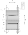
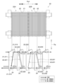
- FIG. 1 is a schematic front view of a composite heat exchanger according to an embodiment. It is an explanatory view for explaining how a refrigerant, a first heat medium, and a second heat medium flow in a composite heat exchanger.
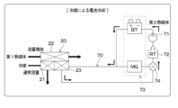
- FIG. 3 is an explanatory diagram for explaining battery cooling using a refrigerant.
- FIG. 3 is an explanatory diagram for explaining battery heating using heat of a first heat medium.
- FIG. 3 is an explanatory diagram for explaining battery heating that does not utilize heat of a first heat medium.
- the heat exchange system 1 for a vehicle is installed, for example, in an electric vehicle that obtains driving force for running the vehicle from an electric motor for running.
- An electric vehicle is capable of charging a large-capacity battery BT mounted on the vehicle with electric power supplied from an external power source when the vehicle is stopped.
- the battery BT is a rechargeable and dischargeable secondary battery.
- the battery BT is composed of, for example, a lithium ion battery that has high energy density, is lightweight, and is compact.
- the heat exchange system 1 includes a vapor compression refrigeration cycle 10 , a high temperature side circuit 50 , a first heat medium circuit 60 including a first heat generating element 64 , a second heat medium circuit 70 including a second heat generating element 73 , and a control unit 100 Equipped with
- the heat exchange system 1 includes a refrigerant flowing through the refrigeration cycle 10, a high temperature side heat medium flowing through the high temperature side circuit 50, a first heat medium flowing through the first heat medium circuit 60, and a second heat medium flowing through the second heat medium circuit 70. Allow heat exchange.
- the refrigeration cycle 10 includes a compressor 11, a condenser 12, a liquid receiving section 13, a subcooling section 14, a first pressure reducing valve 15, an air conditioning evaporator 16, an evaporation pressure regulating valve 17, a second pressure reducing valve 18, and a composite heat It has an exchanger 20.
- the refrigeration cycle 10 uses a refrigerant with a low global warming potential, such as HFO-1234yf.
- the refrigerant includes refrigeration oil for lubricating the compressor 11.
- As the refrigerating machine oil one that is compatible with a liquid phase refrigerant, such as PAG oil, is used.
- a portion of the refrigeration oil circulates within the refrigeration cycle 10 together with the refrigerant.
- the compressor 11 is a device that compresses and discharges refrigerant.
- the compressor 11 is an electric compressor driven by electric power supplied from the battery BT.
- the operation of the compressor 11 is controlled by a control signal output from the control unit 100.
- a condenser 12 is connected to the refrigerant discharge side of the compressor 11.
- the condenser 12 exchanges heat between the high-temperature, high-pressure refrigerant (hereinafter also referred to as high-pressure refrigerant) discharged from the compressor 11 and the high-temperature side heat medium flowing through the high-temperature side circuit 50, and converts the heat of the high-pressure refrigerant into high-temperature side heat. It is a radiator that radiates heat to a medium. When the high-pressure refrigerant passes through the condenser 12, it radiates heat to the high-temperature side heat medium and is condensed.
- the high temperature side heat medium is a fluid flowing through the high temperature side circuit 50.
- the high temperature side heat medium is a liquid phase fluid that does not change phase when flowing through the high temperature side circuit 50.
- a liquid containing ethylene glycol or an antifreeze liquid is used as the high temperature side heat medium.
- the high-temperature side circuit 50 is a circuit for radiating heat from the high-temperature side heat medium to the outside and for heating the interior of the vehicle using the high-temperature side heat medium.
- the high temperature side circuit 50 is provided with a high temperature side pump 51, an electric heater 52, a high temperature side radiator 53, a heater core 54, a high temperature side switching valve 55, and a high temperature side reserve tank 56.
- the high temperature side pump 51 circulates the high temperature side heat medium within the high temperature side circuit 50 by sucking in the high temperature side heat medium and sending it out toward the condenser 12 side.
- the high temperature side pump 51 is an electric pump driven by electric power supplied from the battery BT.
- the high temperature side pump 51 also functions as an adjusting means for adjusting the flow rate of the high temperature side heat medium flowing through the high temperature side circuit 50.
- the electric heater 52 heats the high temperature side heat medium.
- the electric heater 52 is an auxiliary heat source that heats the high-temperature heat medium in situations where the high-temperature heat medium cannot be sufficiently heated by the condenser 12.
- the energization state of the electric heater 52 is controlled by a control signal output from the control unit 100.
- the high temperature side radiator 53 radiates heat from the high temperature side heat medium by exchanging heat with the high temperature side heat medium heated by the condenser 12 and the outside air outside the vehicle compartment.
- the high-temperature side radiator 53 is arranged, for example, on the front side in the traveling direction of the vehicle, and into which the running wind flows when the vehicle is running.
- the heater core 54 is arranged in parallel with the high temperature side radiator 53 in the high temperature side circuit 50.
- the heater core 54 is arranged inside the casing 41 of the air conditioning unit 40.
- the heater core 54 generates conditioned air at a desired temperature by exchanging heat with the high-temperature heat medium heated by the condenser 12 and the air blown into the vehicle interior.
- the high-temperature side switching valve 55 is arranged at a branching portion that branches the flow path of the high-temperature side heat medium into the high-temperature side radiator 53 side and the heater core 54 side.
- the high temperature side switching valve 55 functions as a flow path switching section that switches the flow path of the high temperature side heat medium.
- the high temperature side circuit 50 has a flow path through which the high temperature side heat medium heated in the condenser 12 flows to the heater core 54 and a flow path through which the high temperature side heat medium heated in the condenser 12 flows to the high temperature side radiator 53 by the high temperature side switching valve 55. It is possible to switch between the flow channels.
- the high temperature side switching valve 55 is constituted by a solenoid valve, and its operation is controlled by a control signal output from the control section 100.
- the high temperature side circuit 50 may be provided with a flow rate adjustment valve instead of the high temperature side switching valve 55. In this case, the flow rate of the high-temperature heat medium flowing to the heater core 54 and the flow rate of the high-temperature heat medium flowing to the high-temperature radiator 53 can be adjusted appropriately using the flow rate adjustment valve.
- the high temperature side reserve tank 56 is a tank that stores surplus high temperature side heat medium.
- the high temperature side reserve tank 56 is arranged on the high temperature side heat medium inlet side of the high temperature side pump 51.
- a liquid receiving section 13 is connected to the refrigerant outlet side of the condenser 12.
- the liquid receiving part 13 stores surplus refrigerant in the refrigeration cycle 10.
- the liquid receiving part 13 separates the gas and liquid of the refrigerant flowing out from the condenser 12, and causes the separated liquid phase refrigerant to flow downstream.
- the liquid receiving part 13 may be configured as either a receiver tank with a refrigerant inlet/outlet provided above, or a modulator tank with a refrigerant inlet/outlet provided below.
- a subcooling section 14 is connected to the refrigerant outlet side of the liquid receiving section 13.
- the supercooling section 14 subcools the liquid phase refrigerant by exchanging heat with the high temperature side heat medium before flowing into the condenser 12 with the liquid phase refrigerant flowing out from the liquid receiving section 13 .
- the condenser 12 and the subcooling section 14 constitute a "radiator" that radiates heat from the refrigerant discharged from the compressor 11.
- the refrigerant flow path branches into two.
- a first pressure reducing valve 15 is connected to one flow path on the refrigerant outlet side of the supercooling section 14, and a second pressure reducing valve 18 is connected to the other flow path.
- the first pressure reducing valve 15 is a first pressure reducing section that reduces the pressure of the refrigerant that has passed through the supercooling section 14.
- the first pressure reducing valve 15 is an electric variable throttle whose operation is controlled by a control signal output from the control unit 100, and includes a valve body and an electric actuator.
- the first pressure reducing valve 15 is configured as a variable throttle with a fully closing function that can substantially stop the flow of refrigerant.
- An air conditioning evaporator 16 is connected to the refrigerant outlet side of the first pressure reducing valve 15.
- the air conditioning evaporator 16 and the heater core 54 are arranged inside the casing 41 of the air conditioning unit 40 .
- the air conditioning evaporator 16 evaporates the refrigerant whose pressure has been reduced by the first pressure reducing valve 15 by exchanging heat with the air blown into the vehicle interior.
- the refrigerant absorbs heat from the air blown into the vehicle interior and evaporates, thereby cooling the air.
- the air that has passed through the air conditioning evaporator 16 passes through the heater core 54 and is then supplied into the vehicle interior as conditioned air.
- An evaporation pressure regulating valve 17 is connected to the refrigerant outlet side of the air conditioning evaporator 16.
- the evaporation pressure adjustment valve 17 is a pressure adjustment section that maintains the evaporation pressure of the refrigerant in the air conditioning evaporator 16 to a predetermined reference pressure or higher.
- the evaporation pressure regulating valve 17 adjusts the evaporation pressure of the refrigerant in the air conditioning evaporator 16 so that the temperature of the air conditioning evaporator 16 becomes a temperature (for example, 1° C.) at which frost formation on the air conditioning evaporator 16 is suppressed. It is configured to adjust.
- the second pressure reducing valve 18 is a second pressure reducing section that reduces the pressure of the refrigerant that has passed through the supercooling section 14.
- the second pressure reducing valve 18 is connected to the downstream side of the supercooling section 14 so as to be lined up in parallel with the first pressure reducing valve 15 .
- the second pressure reducing valve 18 is an electric variable throttle whose operation is controlled by a control signal output from the control unit 100, and includes a valve body and an electric actuator.
- the second pressure reducing valve 18 is configured as a variable throttle with a fully closing function that can substantially stop the flow of refrigerant.
- a composite heat exchanger 20 is connected to the refrigerant outlet side of the second pressure reducing valve 18.
- the composite heat exchanger 20 is a chiller that evaporates the refrigerant whose pressure has been reduced by the second pressure reducing valve 18 by exchanging heat with at least one of the first heat medium and the second heat medium.
- the composite heat exchanger 20 includes a refrigerant flow path section 21 through which a refrigerant flows, a first heat medium flow path section 22 through which a first heat medium flows, and a second heat medium flow path section 23 through which a second heat medium flows. .
- the refrigerant flow path section 21, the first heat medium flow path section 22, and the second heat medium flow path section 23 are arranged so that the heat of the refrigerant is transmitted to both the first heat medium and the second heat medium.
- the refrigerant flow path section 21 is an evaporation section that evaporates the refrigerant whose pressure has been reduced by the second pressure reducing valve 18 .
- the refrigerant flow path section 21 is configured such that the cold heat of the refrigerant is transmitted to both the first heat medium and the second heat medium.
- the first heat medium flow path section 22 is arranged adjacent to the coolant flow path section 21 so that the heat of the refrigerant is directly transmitted to the first heat medium.
- the second heat medium flow path section 23 is arranged adjacent to the first heat medium flow path section 22 so that the heat of the refrigerant is indirectly transmitted to the second heat medium via the first heat medium. Further, the first heat medium flow path section 22 and the second heat medium flow path section 23 are arranged adjacently so that the heat of the first heat generation element 64 is transmitted to the second heat medium via the first heat medium. ing. Details of the composite heat exchanger 20 will be described later.
- the first heat medium is a fluid flowing through the first heat medium circuit 60.
- the first heat medium is a liquid phase fluid that does not change phase when flowing through the first heat medium circuit 60.
- a liquid similar to the high temperature side heat medium or an antifreeze liquid is employed.
- the first heat medium circuit 60 includes in-vehicle equipment such as an inverter INV and a transaxle T/A as a first heat generating element 64.
- the first heat medium circuit 60 is a circuit that uses the first heat medium to adjust the temperature of in-vehicle equipment, and uses the first heat medium to absorb heat from the outside.
- the first heat medium circuit 60 is provided with a first circulation pump 61, a first reserve tank 62, a low temperature side radiator 63, and a first heat generating element 64.
- the first circulation pump 61 circulates the first heat medium within the first heat medium circuit 60 by sucking the first heat medium and sending it out toward the composite heat exchanger 20 side.
- the first circulation pump 61 is an electric pump driven by electric power supplied from the battery BT.
- the first circulation pump 61 also functions as an adjusting means for adjusting the flow rate of the first heat medium flowing through the first heat medium circuit 60.
- the first reserve tank 62 is a tank that stores surplus first heat medium.
- the first reserve tank 62 is arranged between the first circulation pump 61 and the first heat generating element 64.
- the low temperature side radiator 63 is connected to the exit side of the first heat medium in the composite heat exchanger 20.
- the low temperature side radiator 63 absorbs heat from the outside air by exchanging heat with the first heat medium that has passed through the composite heat exchanger 20 and the outside air outside the vehicle interior.
- the low-temperature side radiator 63 is arranged, for example, along with the high-temperature side radiator 53 on the front side in the traveling direction of the vehicle.
- the high temperature side radiator 53 and the low temperature side radiator 63 are arranged in series in this order in the flow direction of the outside air.
- the high-temperature side radiator 53 and the low-temperature side radiator 63 are connected to each other by common heat transfer fins (not shown) so that heat can be transferred to each other.
- the first heat generating element 64 is a heat generating device such as an inverter INV or a transaxle T/A.
- the first heat generating element 64 is maintained at an appropriate temperature by radiating heat to the first heat medium.
- the first heat medium circuit 60 absorbs heat from the first heat generating element 64 via the first heat medium.
- the on-vehicle equipment that constitutes the first heat generating element 64 may be different from those described above.
- the second heat medium is a fluid flowing through the second heat medium circuit 70.
- the second heat medium is a liquid phase fluid that does not change phase when flowing through the second heat medium circuit 70.
- a liquid for example, oil
- the second heat medium is a highly electrically insulating liquid, current leakage through the second heat medium is suppressed. .
- the second heat medium circuit 70 is configured as an independent circuit with respect to the first heat medium circuit 60.
- the second heat medium circuit 70 includes a plurality of heat generating elements such as a battery BT and a motor generator MG as a second heat generating element 73.
- the second heat medium circuit 70 is a circuit for adjusting the temperature of the battery BT and motor generator MG, which are heating elements, using a second heat medium.
- the second heat medium circuit 70 is provided with a second circulation pump 71, a second reserve tank 72, a second heat generating element 73, and a flow path switching valve 74.
- the second circulation pump 71 circulates the first heat medium within the second heat medium circuit 70 by sucking in the second heat medium and sending it out toward the battery BT side.
- the second circulation pump 71 is an electric pump driven by electric power supplied from the battery BT.
- the second circulation pump 71 also functions as an adjusting means for adjusting the flow rate of the second heat medium flowing through the second heat medium circuit 70.
- the second reserve tank 72 is a tank that stores surplus second heat medium.
- the second reserve tank 72 is arranged between the second circulation pump 71 and the flow path switching valve 74.
- the second heat generating element 73 is a heat generating device such as a battery BT or a motor generator MG.
- the second heat generating element 73 is maintained at an appropriate temperature by radiating heat to or absorbing heat from the second heat medium.
- Motor generator MG is arranged in parallel with second heat medium flow path section 23 in second heat medium circuit 70 . Note that the on-vehicle equipment that constitutes the second heat generating element 73 may be different from those described above.
- the flow path switching valve 74 is a three-way valve that switches the flow path of the second heat medium.
- the flow path switching valve 74 has a flow path through which the second heat medium sent out from the second circulation pump 71 flows in the order of battery BT ⁇ second heat medium flow path part 23 of the composite heat exchanger 20, and a flow path through which the second heat medium sent out from the second circulation pump 71 flows from battery BT ⁇ motor.
- the flow path is switched to the flow path that flows in the order of generator MG.
- the operation of the flow path switching valve 74 is controlled by a control signal output from the control unit 100.
- the second heat medium circuit 70 is configured to be able to transfer the heat of the motor generator MG to the battery BT via the second heat medium by being provided with a flow path switching valve 74.
- the second heat medium circuit 70 may be provided with a flow rate adjustment valve instead of the flow path switching valve 74.
- the flow rate adjustment valve can appropriately adjust the flow rate of the second heat medium flowing to motor generator MG and the flow rate of the second heat medium flowing to composite heat exchanger 20.
- FIGS. 2 and 3 The arrows indicating up and down in FIGS. 2 and 3 indicate the up and down direction Dg when the composite heat exchanger 20 is mounted on a vehicle.
- the composite heat exchanger 20 is configured as a plate laminated heat exchanger.
- the composite heat exchanger 20 is formed by stacking and joining a large number of plate members 24.
- the composite heat exchanger 20 is mounted on a vehicle with the stacking direction Dst of the many plate-like members 24 intersecting the vertical direction Dg.
- the large number of plate members 24 are elongated, generally rectangular plates.
- the plate member 24 is made of a metal core material made of aluminum alloy or the like, and both sides of which are clad with brazing material.
- a sacrificial layer is formed on at least one side of the core material of the plate member 24.
- the sacrificial layer is made of an aluminum alloy containing a predetermined proportion of a material (for example, Zn) that is more base in potential than the core material.
- the plate-like member 24 is provided with a protruding portion protruding to one side in the stacking direction Dst at its outer peripheral edge portion. A large number of plate-like members 24 are stacked on top of each other, and their protruding portions are joined by brazing.
- the refrigerant flow path section 21 passes through a plurality of refrigerant flow paths 211 formed between adjacent plate members 24, a refrigerant distribution section 212 that distributes refrigerant to the plurality of refrigerant flow paths 211, and a plurality of refrigerant flow paths 211. It has a refrigerant collection part 213 that collects the refrigerant.
- the plurality of refrigerant channels 211 are heat exchange portions that exchange heat between the refrigerant and the first heat medium, and extend along the plate surface of the plate member 24 .
- the refrigerant distribution section 212 and the refrigerant collection section 213 are constructed by joining substantially cylindrical tubular sections provided on the plate member 24 to each other. The refrigerant distribution section 212 and the refrigerant collection section 213 extend in the stacking direction Dst.
- a refrigerant distribution section 212 is formed above the refrigerant flow path 211 , and a refrigerant collection section 213 is formed below the refrigerant flow path 211 .
- the refrigerant passage section 21 is configured so that the refrigerant flows downward.
- the refrigerant flow path section 21 is constituted by the plate-like member 24 on the other side in the stacking direction Dst among the many plate-like members 24.
- the refrigerant flow path section 21 is arranged adjacent to the first heat medium flow path section 22 so that the heat of the refrigerant is directly transmitted to the first heat medium.
- the refrigerant flow path portion 21 is arranged such that the entire refrigerant flow path 211, which is a heat exchange portion, is in thermal contact with the first heat medium flow path portion 22.
- the second heat medium flow path section 23 includes a plurality of second heat medium flow paths 231 formed between adjacent plate members 24, and a second heat medium that distributes the second heat medium to the second heat medium flow paths 231. It has a medium distribution section 232 and a second heat medium collection section 233 that collects the second heat medium that has passed through the second heat medium flow path 231.
- the plurality of second heat medium channels 231 are heat exchange parts that exchange heat between the second heat medium and the first heat medium, and extend along the plate surface of the plate-shaped member 24 .
- the second heat medium distribution section 232 and the second heat medium gathering section 233 are configured by joining substantially cylindrical tubular sections provided on the plate member 24 to each other.
- the second heat medium distribution section 232 and the second heat medium gathering section 233 extend in the stacking direction Dst.
- a second heat medium distribution section 232 is formed below the second heat medium flow path 231, and a second heat medium collection section 233 is formed above the second heat medium flow path 231. has been done.
- the second heat medium flow path portion 23 is configured such that the second heat medium flows upward.
- the second heat medium flow path portion 23 is constituted by a plate-like member 24 on one side in the stacking direction Dst among the many plate-like members 24.
- the second heat medium flow path section 23 is arranged adjacent to the first heat medium flow path section 22 so that the heat of the refrigerant is indirectly transmitted via the first heat medium.
- the second heat medium flow path section 23 is arranged such that the entire second heat medium flow path 231, which is a heat exchange section, is in thermal contact with the first heat medium flow path section 22.
- the first heat medium flow path section 22 includes a plurality of first heat medium flow paths 221 formed between adjacent plate-like members 24 , and distribution of the first heat medium to the plurality of first heat medium flow paths 221 . , has a tank portion 222 that collects the refrigerant that has passed through the plurality of first heat medium channels 221.
- the plurality of first heat medium channels 221 are heat exchange parts that exchange heat between the first heat medium and the refrigerant or the second heat medium, and extend along the plate surface of the plate member 24 .
- the tank portion 222 is configured by joining substantially cylindrical tubular portions provided on the plate member 24 to each other. The tank portion 222 extends in the stacking direction Dst.
- the first heat medium flow path section 22 includes a first heat exchange section 22A that exchanges heat between the first heat medium and the refrigerant, and a second heat exchange section 22B that exchanges heat between the first heat medium and the second heat medium. has.
- the first heat medium flow path section 22 is configured such that the first heat medium flows in the order of the first heat exchange section 22A and the second heat exchange section 22B.
- first heat medium flow paths 221 and refrigerant flow paths 211 are arranged alternately.
- the first heat medium flow path 221 constituting the first heat exchange section 22A is configured such that the first heat medium flows upward. Thereby, in the refrigerant flow path section 21 and the first heat medium flow path section 22, the refrigerant and the first heat medium flow in opposite directions.
- the first heat medium flow path 221 and the second heat medium flow path 231 are arranged alternately.
- the first heat medium flow path 221 constituting the second heat exchange section 22B is configured such that the first heat medium flows downward. Thereby, in the first heat medium flow path section 22 and the second heat medium flow path section 23, the first heat medium and the second heat medium flow in opposite directions.
- the flow direction of the first heat medium in the first heat exchange section 22A is opposite to the flow direction of the first heat medium in the second heat exchange section 22B. That is, the first heat medium flow path section 22 has a structure in which the flow of the first heat medium makes a U-turn.
- the refrigerant flows downward through the refrigerant flow path section 21, and the second heat medium flows upward through the second heat medium flow path section 23.
- the refrigerant and the second heat medium flow in opposite directions.
- the heat exchange system 1 including the composite heat exchanger 20 configured as described above includes a control unit 100 for controlling various component devices.
- the control unit 100 is composed of a microcomputer including a processor and a memory, and its peripheral circuits.
- the control unit 100 performs various calculations and processes based on a control program stored in a memory.
- the memory of the control unit 100 is composed of a non-transitional physical storage medium.
- a compressor 11 On the output side of the control unit 100, there are a compressor 11, a first pressure reducing valve 15, a second pressure reducing valve 18, a high temperature side pump 51, an electric heater 52, a high temperature side switching valve 55, a first circulation pump 61, and a second circulation pump. 71, a flow path switching valve 74, etc. are connected.
- the heat exchange system 1 changes the flow rate of the refrigerant flowing through the refrigerant flow path section 21 and the first heat medium flow path section by changing the operations of the second pressure reducing valve 18, each circulation pump 61, 71, and the flow path switching valve 74.
- the flow rate of the first heat medium flowing through the heat transfer medium 22 and the flow rate of the second heat medium flowing through the second heat medium flow path portion 23 can be changed.
- the second pressure reducing valve 18 , each circulation pump 61 , 71 , and the flow path switching valve 74 control the flow rate of the refrigerant flowing through the refrigerant flow path section 21 and the flow rate of the first heat medium flowing through the first heat medium flow path section 22 .
- a flow rate adjusting section is configured to adjust the flow rate of the second heat medium flowing through the second heat medium flow path section 23.
- a sensor group for air conditioning control and a sensor group for equipment temperature control are connected to the input side of the control unit 100. Further, various operation switches are connected to the input side of the control unit 100, and operation signals of the various operation switches are inputted.
- Various operation switches include air conditioner switch, room temperature adjustment switch, etc.
- the air conditioner switch is a switch for setting whether or not the air conditioning unit 40 cools the air.
- the room temperature adjustment switch is a switch that sets a set temperature in the vehicle interior.
- the control unit 100 switches the operation mode of the heat exchange system 1 based on sensor outputs of a sensor group for air conditioning control and a sensor group for equipment temperature control, operation signals of various operation switches, etc.
- control unit 100 calculates a target blowout temperature of the conditioned air that is blown into the vehicle interior from the air conditioning unit 40, and sets the operation mode of the heat exchange system 1 to a cooling mode, a heating mode, or a heating mode based on the target blowout temperature. Switch to one of the dehumidifying heating modes.
- control unit 100 determines control signals to be output to various devices connected to the control unit 100 based on the target blowout temperature, sensor outputs of various sensor groups, and the like.
- control unit 100 drives the compressor 11, controls the first pressure reducing valve 15 to be in the throttled state, and controls the second pressure reducing valve 18 to be in the fully closed state.
- control signal output to the first pressure reducing valve 15 the control unit 100 determines the degree of superheat on the refrigerant outlet side of the air conditioning evaporator 16 to be a predetermined first target degree of superheat.
- control unit 100 drives the high temperature side pump 51 and controls the high temperature side switching valve 55 so that the high temperature side heat medium flows to the high temperature side radiator 53.
- refrigerant discharged from the compressor 11 flows into the condenser 12.
- the refrigerant flowing into the condenser 12 radiates heat to the high temperature side heat medium flowing through the high temperature side circuit 50.
- the refrigerant flowing through the condenser 12 is cooled and condensed.
- the high temperature side heat medium radiates heat to the outside air when passing through the high temperature side radiator 53.
- the refrigerant that has passed through the condenser 12 is separated into gas and liquid by the liquid receiving part 13, and the excess liquid phase refrigerant in the cycle is stored inside the liquid receiving part 13.
- the liquid phase refrigerant stored in the liquid receiving part 13 is supercooled in the supercooling part 14 by exchanging heat with the high temperature side heat medium before passing through the condenser 12 .
- the liquid phase refrigerant that has passed through the supercooling section 14 is depressurized by the first pressure reducing valve 15.
- the refrigerant whose pressure has been reduced by the first pressure reducing valve 15 flows into the air conditioning evaporator 16, absorbs heat from the air blown into the vehicle interior, and evaporates. Thereby, the air blown into the vehicle interior is cooled until it reaches a desired temperature.
- the refrigerant that has passed through the air conditioning evaporator 16 flows to the suction side of the compressor 11 and is compressed by the compressor 11 again.
- the air blown into the vehicle interior is cooled by exchanging heat with the refrigerant in the air conditioning evaporator 16 with the air blown into the vehicle interior. This achieves cooling of the vehicle interior.
- the control unit 100 drives at least one of the first circulation pump 61 and the second circulation pump 71, and also drives the first circulation pump 61 and the second circulation pump 71. 2. Control the pressure reducing valve 18 to a throttled state.
- the control unit 100 drives the first circulation pump 61 while stopping the second circulation pump 71, and also controls the second pressure reducing valve 18 to a throttled state. to control.
- part of the refrigerant that has passed through the supercooling section 14 flows into the second pressure reducing valve 18 and is depressurized.
- the refrigerant whose pressure has been reduced by the second pressure reducing valve 18 absorbs heat from the first heat medium flowing through the first heat medium flow path section 22 and evaporates in the refrigerant flow path section 21 of the composite heat exchanger 20 .
- the first heat medium flowing through the first heat medium circuit 60 is cooled.
- the first heat medium cooled by the composite heat exchanger 20 circulates through the first heat medium circuit 60, thereby cooling the first heat generating element 64.
- the control unit 100 drives each circulation pump 61, 71 and controls the second pressure reducing valve 18 to a throttled state. Further, as shown in FIG. 4, the control unit 100 causes the second heat medium sent out from the second circulation pump 71 to flow in the order of battery BT ⁇ second heat medium flow path section 23 of the composite heat exchanger 20. , controls the flow path switching valve 74. Further, the control unit 100 controls the first circulation pump 61 so that the flow rate of the first heat medium flowing through the composite heat exchanger 20 is increased compared to before the battery cooling condition is satisfied.
- the second pressure reducing valve 18 a part of the refrigerant that has passed through the supercooling section 14 flows into the second pressure reducing valve 18 and is depressurized.
- the refrigerant whose pressure has been reduced by the second pressure reducing valve 18 absorbs heat from the first heat medium flowing through the first heat medium flow path section 22 and evaporates in the refrigerant flow path section 21 of the composite heat exchanger 20 .
- the second heat medium is cooled by heat exchange between the first heat medium and the second heat medium.
- the second heat medium cooled by the composite heat exchanger 20 circulates through the second heat medium circuit 70, thereby cooling the battery BT of the second heat generating element 73.
- the control unit 100 heats the battery BT using the heat of the first heat medium.
- the control unit 100 drives each of the circulation pumps 61 and 71, and also opens the second pressure reducing valve 18 by a small throttle so that the flow rate of the refrigerant flowing through the refrigerant flow path section 21 of the composite heat exchanger 20 is reduced. control to close or fully closed state.
- the control unit 100 causes the second heat medium sent out from the second circulation pump 71 to flow in the order of the battery BT ⁇ the second heat medium flow path section 23 of the composite heat exchanger 20. , controls the flow path switching valve 74.
- the first heat medium that has received heat from the first heat generating element 64 and has been heated flows into the first heat medium flow path section 22 of the composite heat exchanger 20. Since the flow rate of the refrigerant flowing through the refrigerant flow path section 21 is small, in the composite heat exchanger 20, heat exchange is dominant between the first heat medium and the second heat medium. Therefore, the first heat medium flowing into the first heat medium flow path section 22 radiates heat through heat exchange with the second heat medium flowing through the second heat medium flow path section 23 . In other words, the second heat medium flowing through the second heat medium flow path section 23 receives heat from the first heat medium and rises in temperature. Thereby, the second heat medium heated by the composite heat exchanger 20 circulates through the second heat medium circuit 70, thereby heating the battery BT of the second heating element 73.
- the control unit 100 determines control signals to be output to various devices connected to the control unit 100 based on the target blowout temperature, sensor outputs of various sensor groups, and the like.
- the control unit 100 drives the compressor 11, controls the first pressure reducing valve 15 to be fully closed, and controls the second pressure reducing valve 18 to be in the throttled state.
- the control unit 100 determines the degree of superheat on the refrigerant outlet side of the composite heat exchanger 20 to be a predetermined second target degree of superheat.
- the control unit 100 drives the high temperature side pump 51 and controls the high temperature side switching valve 55 so that the high temperature side heat medium flows into the heater core 54 .
- the control unit 100 drives the first circulation pump 61 so that the first heat medium flows into the low temperature side radiator 63.
- refrigerant discharged from the compressor 11 flows into the condenser 12.
- the refrigerant flowing into the condenser 12 radiates heat to the high temperature side heat medium flowing through the high temperature side circuit 50.
- the refrigerant flowing through the condenser 12 is cooled and condensed.
- the high-temperature side heat medium radiates heat to the air blown into the vehicle interior through the heater core 54. As a result, the air blown into the vehicle interior is heated.
- the refrigerant that has passed through the condenser 12 is separated into gas and liquid by the liquid receiving part 13, and the excess liquid phase refrigerant in the cycle is stored inside the liquid receiving part 13.
- the liquid phase refrigerant stored in the liquid receiving part 13 is supercooled in the supercooling part 14 by exchanging heat with the high temperature side heat medium before passing through the condenser 12 .
- the liquid phase refrigerant that has passed through the supercooling section 14 is depressurized by the second pressure reducing valve 18.
- the refrigerant whose pressure has been reduced by the second pressure reducing valve 18 flows into the refrigerant flow path section 21 of the composite heat exchanger 20, absorbs heat from the first heat medium flowing through the first heat medium flow path section 22, and evaporates.
- the refrigerant that has passed through the composite heat exchanger 20 flows to the suction side of the compressor 11 and is compressed by the compressor 11 again.
- the first heat medium that has passed through the first heat medium flow path section 22 of the composite heat exchanger 20 absorbs heat from the outside air when passing through the low temperature side radiator 63. Therefore, the refrigerant flowing through the refrigerant flow path section 21 of the composite heat exchanger 20 absorbs heat from the outside air via the first heat medium.
- the first heat medium also absorbs heat from the first heat generating element 64 when passing through the first heat generating element 64.
- the refrigerant flowing through the refrigerant flow path portion 21 of the composite heat exchanger 20 also absorbs heat from the first heat generating element 64 via the first heat medium.
- the refrigerant discharged from the compressor 11 is radiated to the high temperature side heat medium in the condenser 12 and the subcooling section 14, and the high temperature side heat medium of the high temperature side circuit 50 is transferred to the heater core 54 to drive the vehicle.
- the air blown into the cabin radiates heat and heats the air blown into the cabin. This achieves heating of the vehicle interior.
- the first heat medium flowing through the low-temperature side radiator 63 absorbs heat from the outside air, so frost may form on the low-temperature side radiator 63.
- frost forms on the low temperature side radiator 63, heat exchange between the first heat medium and the outside air is restricted.
- the low-temperature side radiator 63 of this embodiment is connected to the high-temperature side radiator 53 through a common heat transfer fin so that heat can be transferred. Therefore, for example, when the vehicle is stopped after executing the heating mode, the heat remaining in the high temperature side heat medium of the high temperature side circuit 50 can be used to defrost the low temperature side radiator 63.
- the control unit 100 drives the second circulation pump 71.
- the control unit 100 also controls the flow path switching valve 74 so that the second heat medium sent out from the second circulation pump 71 flows in the order of battery BT ⁇ second heat medium flow path portion 23 of the composite heat exchanger 20.
- Control Further, the control unit 100 controls the first circulation pump 61 so that the flow rate of the first heat medium flowing through the composite heat exchanger 20 is increased compared to before the battery cooling condition is satisfied.
- the refrigerant whose pressure has been reduced by the second pressure reducing valve 18 absorbs heat from the first heat medium flowing through the first heat medium flow path section 22 and evaporates in the refrigerant flow path section 21 of the composite heat exchanger 20. do.
- the second heat medium is cooled by heat exchange between the first heat medium and the second heat medium.
- the second heat medium cooled by the composite heat exchanger 20 circulates through the second heat medium circuit 70, thereby cooling the battery BT of the second heat generating element 73.
- the control unit 100 heats the battery BT.
- the composite heat exchanger 20 causes the first heat medium to radiate heat to the refrigerant. Therefore, in the heating mode, it may be difficult to sufficiently heat the battery BT using the heat of the first heat medium.
- the control unit 100 heats the battery BT without using the heat of the first heat medium.
- the control unit 100 drives each of the circulation pumps 61 and 71 and controls the second pressure reducing valve 18 to be in a throttled state. Further, as shown in FIG. 6, the control unit 100 controls the flow path switching valve 74 so that the second heat medium sent out from the second circulation pump 71 flows in the order of battery BT ⁇ motor generator MG.
- the battery BT can radiate heat from the second heat medium that has received heat from the motor generator MG and has increased in temperature. That is, battery BT of second heating element 73 is heated by the second heat medium that has received heat from motor generator MG and has increased in temperature.
- the temperature of the first heat medium after heat exchange with the refrigerant in the composite heat exchanger 20 is higher than the temperature of the battery BT, battery heating using the heat of the first heat medium becomes possible.
- the battery similarly to the cooling mode, the battery may be heated using the heat of the first heat medium.
- the flow rate of the refrigerant flowing through the composite heat exchanger 20 in the heating mode is reduced, the amount of heat absorbed by the refrigerant in the composite heat exchanger 20 is reduced, so that the amount of heat absorbed by the refrigerant in the composite heat exchanger 20 is reduced in the heating mode. It is desirable to control the second pressure reducing valve 18 so that the flow rate of the refrigerant does not decrease.
- the control unit 100 determines control signals to be output to various devices connected to the control unit 100 based on the target blowout temperature, sensor outputs of various sensor groups, and the like.
- control unit 100 drives the compressor 11, controls the first pressure reducing valve 15 to be in the throttled state, and controls the second pressure reducing valve 18 to be in the fully closed state.
- control unit 100 determines the degree of superheat on the refrigerant outlet side of the air conditioning evaporator 16 to be a predetermined third target degree of superheat.
- control unit 100 drives the high temperature side pump 51 and controls the high temperature side switching valve 55 so that the high temperature side heat medium flows into the heater core 54 .
- refrigerant discharged from the compressor 11 flows into the condenser 12.
- the refrigerant flowing into the condenser 12 radiates heat to the high temperature side heat medium flowing through the high temperature side circuit 50.
- the refrigerant flowing through the condenser 12 is cooled and condensed.
- the high-temperature side heat medium radiates heat to the air blown into the vehicle interior through the heater core 54. As a result, the air blown into the vehicle interior is heated.
- the refrigerant that has passed through the condenser 12 is separated into gas and liquid by the liquid receiving part 13, and the excess liquid phase refrigerant in the cycle is stored inside the liquid receiving part 13.
- the liquid phase refrigerant stored in the liquid receiving part 13 is supercooled in the supercooling part 14 by exchanging heat with the high temperature side heat medium before passing through the condenser 12 .
- the liquid phase refrigerant that has passed through the supercooling section 14 is depressurized by the second pressure reducing valve 18.
- the refrigerant whose pressure has been reduced by the first pressure reducing valve 15 flows into the air conditioning evaporator 16, absorbs heat from the air before being heated by the heater core 54, and evaporates. As a result, the air blown into the vehicle interior is dehumidified.
- the refrigerant that has passed through the air conditioning evaporator 16 flows to the suction side of the compressor 11 and is compressed by the compressor 11 again.
- the refrigerant discharged from the compressor 11 is radiated to the high temperature side heat medium in the condenser 12 and the subcooling section 14, and the high temperature side heat medium of the high temperature side circuit 50 is transferred to the heater core 54. Heat is radiated into the air blown into the vehicle interior.
- the refrigerant whose pressure has been reduced by the first pressure reducing valve 15 is evaporated by exchanging heat with the air blown into the vehicle interior by the air conditioning evaporator 16. Thereby, the air dehumidified by the air conditioning evaporator 16 can be heated by the heater core 54 and blown out into the vehicle interior.
- the control unit 100 drives the first circulation pump 61 while stopping the second circulation pump 71, and also controls the second pressure reducing valve 18 to a throttled state. to control.
- part of the refrigerant that has passed through the supercooling section 14 flows into the second pressure reducing valve 18 and is depressurized.
- the refrigerant whose pressure has been reduced by the second pressure reducing valve 18 absorbs heat from the first heat medium flowing through the first heat medium flow path section 22 and evaporates in the refrigerant flow path section 21 of the composite heat exchanger 20 .
- the first heat medium flowing through the first heat medium circuit 60 is cooled.
- the first heat medium cooled by the composite heat exchanger 20 circulates through the first heat medium circuit 60, thereby cooling the first heat generating element 64.
- the control unit 100 drives each circulation pump 61, 71 and controls the second pressure reducing valve 18 to a throttled state.
- the control unit 100 also controls the flow path switching valve 74 so that the second heat medium sent out from the second circulation pump 71 flows in the order of battery BT ⁇ second heat medium flow path portion 23 of the composite heat exchanger 20.
- Control Further, the control unit 100 controls the first circulation pump 61 so that the flow rate of the first heat medium flowing through the composite heat exchanger 20 is increased compared to before the battery cooling condition is satisfied.
- the second pressure reducing valve 18 a part of the refrigerant that has passed through the supercooling section 14 flows into the second pressure reducing valve 18 and is depressurized.
- the refrigerant whose pressure has been reduced by the second pressure reducing valve 18 absorbs heat from the first heat medium flowing through the first heat medium flow path section 22 and evaporates in the refrigerant flow path section 21 of the composite heat exchanger 20 .
- the second heat medium is cooled by heat exchange between the first heat medium and the second heat medium.
- the second heat medium cooled by the composite heat exchanger 20 circulates through the second heat medium circuit 70, thereby cooling the battery BT of the second heat generating element 73.
- the control unit 100 uses the heat of the first heat medium to heat the battery BT, as in the cooling mode.
- Heat For example, the control unit 100 drives each of the circulation pumps 61 and 71, and also opens the second pressure reducing valve 18 by a small throttle so that the flow rate of the refrigerant flowing through the refrigerant flow path section 21 of the composite heat exchanger 20 is reduced. control to close or fully closed state.
- the control unit 100 also controls the flow path switching valve 74 so that the second heat medium sent out from the second circulation pump 71 flows in the order of battery BT ⁇ second heat medium flow path portion 23 of the composite heat exchanger 20. Control.
- the first heat medium that has received heat from the first heat generating element 64 and has been heated flows into the first heat medium flow path section 22 of the composite heat exchanger 20.
- the first heat medium flowing into the first heat medium flow path section 22 radiates heat through heat exchange with the second heat medium flowing through the second heat medium flow path section 23 .
- the second heat medium flowing through the second heat medium flow path section 23 receives heat from the first heat medium and increases in temperature.
- the second heat medium heated by the composite heat exchanger 20 circulates through the second heat medium circuit 70, thereby heating the battery BT of the second heat generating element 73.
- the heat exchange system 1 described above includes a refrigerant circulating in the refrigeration cycle 10, a first heat medium flowing through the first heat medium circuit 60 including the first heat generating element 64, and a second heat medium circuit 70 including the second heat generating element 73.
- a composite heat exchanger 20 is provided for exchanging heat with the second heat medium flowing through the second heat medium.
- the composite heat exchanger 20 includes a refrigerant flow path section 21 through which a refrigerant flows, a first heat medium flow path section 22 through which a first heat medium flows, and a second heat medium flow path section 23 through which a second heat medium flows. Equipped with The refrigerant flow path section 21, the first heat medium flow path section 22, and the second heat medium flow path section 23 are arranged so that the heat of the refrigerant is transmitted to both the first heat medium and the second heat medium.
- the composite heat exchanger 20 of the present disclosure three types of fluids, such as the refrigerant, the first heat medium, and the second heat medium, can be heat exchanged with a single heat exchanger. Therefore, the heat of the refrigerant can be supplied to the first heat medium and the second heat medium while suppressing the complexity of the cycle configuration of the refrigeration cycle 10.
- the composite heat exchanger 20 of the present disclosure enables cost reduction and size reduction. Furthermore, since the cycle configuration and circuit configuration become compact, heat loss can be reduced.
- composite heat exchanger 20 of this embodiment includes the following features.
- the first heat medium is a liquid phase fluid that does not change phase when flowing through the first heat medium circuit 60.
- the first heat medium flow path section 22 is arranged adjacent to the coolant flow path section 21 so that the heat of the refrigerant is directly transmitted to the first heat medium.
- the second heat medium flow path section 23 is arranged adjacent to the first heat medium flow path section 22 so that the heat of the refrigerant is indirectly transmitted to the second heat medium via the first heat medium. .
- heat of the refrigerant can be appropriately supplied to both the first heat medium and the second heat medium.
- the first heat medium flow path section 22 and the second heat medium flow path section 23 are arranged adjacently so that the heat of the first heat generation element 64 is transmitted to the second heat medium via the first heat medium. ing.
- this configuration it becomes possible to adjust the temperature of the second heat generating element 73 using not only the heat of the refrigerant but also the heat of the first heat generating element 64. This cannot be achieved by adding a heat exchanger for exchanging heat between the refrigerant and the first heat medium and a heat exchanger for exchanging heat between the refrigerant and the second heat medium to the refrigeration cycle 10. This is a unique effect.
- the refrigeration cycle 10 includes a compressor 11 that compresses and discharges refrigerant, a condenser 12 that radiates heat from the refrigerant discharged from the compressor 11, a supercooling section 14, and a decompression of the refrigerant that has passed through the supercooling section 14.
- a second pressure reducing valve 18 is included.
- the refrigerant flow path section 21 constitutes an evaporation section that evaporates the refrigerant whose pressure has been reduced by the second pressure reducing valve 18 .
- the refrigerant flow path section 21 is configured such that the cold heat of the refrigerant is transmitted to both the first heat medium and the second heat medium. According to this, it becomes possible to appropriately cool the first heat generating element 64 and the second heat generating element 73 by absorbing heat from the first heat medium and the second heat medium using the latent heat of evaporation of the refrigerant.
- the first heat medium circuit 60 is provided with a low-temperature side radiator 63 that exchanges heat between the first heat medium and the outside air. According to this, the heat of the outside air and the heat of the first heat generating element 64 can be transferred to the refrigerant via the first heat medium, and the refrigeration cycle 10 can function as a heat pump cycle that absorbs heat from the outside air or the like.
- the second heat generating element 73 includes a battery BT as a heat generating body. According to this, the temperature of the battery BT can be adjusted using the heat of the refrigerant and the heat of the first heat medium.
- the second heat generating element 73 includes a plurality of heat generating bodies such as a battery BT and a motor generator MG.
- the second heat medium circuit 70 is configured to be able to transfer heat from some of the plurality of heat generating elements to other heat generating elements other than some of the heat generating elements via the second heat medium. There is. According to this, in the second heat medium circuit 70, it becomes possible to adjust the temperature of other heat generating elements by using the heat of some of the plurality of heat generating elements.
- the second heat medium circuit 70 includes a flow path through which the second heat medium sent out from the second circulation pump 71 flows in the order of battery BT ⁇ second heat medium flow path section 23, and a flow path through which the second heat medium sent out from the second circulation pump 71 flows from battery BT ⁇ motor.
- a flow path switching valve 74 is provided to switch the flow path to the flow path in which the generator MG flows.
- the second heat medium has higher electrical insulation than the first heat medium. According to this, the leakage of the second heat generating element 73 via the second heat medium is suppressed, so the temperature of the battery BT etc. included in the second heat generating element 73 can be safely adjusted via the second heat medium. be able to.
- the refrigerant flow path section 21 is adjacent to the first heat medium flow path section 22 so that the heat of the refrigerant is directly transferred to the first heat medium, and the entire heat exchange portion in the refrigerant flow path section 21 is It is arranged so as to be in thermal contact with the first heat medium flow path section 22 . According to this, heat exchange between the refrigerant flowing through the refrigerant flow path section 21 and the first heat medium flowing through the first heat medium flow path section 22 can be promoted.
- the refrigerant flow path section 21 of this embodiment is configured as an evaporation section that evaporates the refrigerant
- the refrigerant flow path section is configured to promote heat exchange between the refrigerant and the first heat medium. 21 makes it easier to evaporate the refrigerant. As a result, liquid backflow to the compressor 11 can be suppressed and the compressor 11 can be protected.
- the first heat medium flow path section 22 includes a first heat exchange section 22A that exchanges heat between the first heat medium and the refrigerant, and a second heat exchange section that exchanges heat between the first heat medium and the second heat medium. 22B, and the first heat medium is configured to flow through the first heat exchange section 22A and the second heat exchange section 22B in this order. According to this, the entire amount of the first heat medium flows through each of the first heat exchange section 22A and the second heat exchange section 22B. Therefore, it is possible to ensure a sufficient amount of heat exchange between the refrigerant and the first heat medium in the first heat exchange section 22A and a sufficient amount of heat exchange between the first heat medium and the second heat medium in the second heat exchange section 22B. can.
- Refrigerant oil is included in the refrigerant.
- the refrigerant passage section 21 is configured so that the refrigerant flows downward. According to this, it is possible to suppress refrigerating machine oil from remaining in the composite heat exchanger 20. As a result, the compressor 11 can be protected by lubricating the sliding parts of the compressor 11 with the refrigerating machine oil.
- the refrigerant flow path section 21 and the first heat medium flow path section 22 are arranged so that the refrigerant and the first heat medium flow in opposite directions. Moreover, the first heat medium flow path section 22 and the second heat medium flow path section 23 are arranged so that the first heat medium and the second heat medium flow in opposite directions. According to this, the temperature difference between the refrigerant and the first heat medium and the temperature difference between the first heat medium and the second heat medium are ensured to ensure appropriate heat exchange between the refrigerant, the first heat medium, and the second heat medium. It can be implemented.
- the heat exchange system 1 includes a flow rate of the refrigerant flowing through the refrigerant flow path section 21, a flow rate of the first heat medium flowing through the first heat medium flow path section 22, a second heat medium flow rate, and a flow rate of the first heat medium flowing through the first heat medium flow path section 22.
- a flow rate adjustment section that adjusts the flow rate of the second heat medium flowing through the medium flow path section 23 is provided.
- the refrigerant flow path section 21, the first heat medium flow path section 22, and the second heat medium flow path section 23 are arranged so that the heat of the refrigerant is transmitted to both the first heat medium and the second heat medium. There is.
- the first heat medium flow path section 22 is arranged adjacent to the coolant flow path section 21 so that the heat of the refrigerant is directly transmitted to the first heat medium. Further, the second heat medium flow path section 23 is arranged adjacent to the first heat medium flow path section 22 so that the heat of the refrigerant is indirectly transmitted to the second heat medium via the first heat medium. . Then, when the operating mode is set to exchange heat between the refrigerant and the second heat medium via the first heat medium, the flow rate adjustment section increases the flow rate of the first heat medium flowing through the first heat medium flow path section 22 . According to this, it is possible to sufficiently secure the amount of heat exchange between the refrigerant and the first heat medium and the amount of heat exchange between the first heat medium and the second heat medium. This contributes to improving the heat transfer efficiency in the composite heat exchanger 20.
- the control unit 100 increases the discharge capacity of the first heat medium in the first circulation pump 61.
- the flow rate of the first heat medium flowing through the first heat medium flow path section 22 is increased.
- the cold heat of the refrigerant is easily transmitted to the second heat generating element 73 via the first heat medium and the second heat medium, so that the second heat generating element 73 can be appropriately cooled.
- the first heat medium flow path section 22 and the second heat medium flow path section 23 are arranged adjacently so that the heat of the first heat generation element 64 is transmitted to the second heat medium via the first heat medium. ing.
- the flow rate adjustment section reduces the flow rate of the refrigerant flowing through the refrigerant flow path section 21 when the operation mode is set to transfer the heat of the first heat generating element 64 to the second heat medium. With this configuration, the heat of the first heat generating element 64 can be appropriately transferred to the second heat medium while suppressing heat exchange between the first heat medium and the refrigerant. This contributes to improving the heat transfer efficiency in the composite heat exchanger 20.
- the control unit 100 controls the second pressure reducing valve 18 to a minute throttle opening or a fully closed state.
- the flow rate of the refrigerant flowing through the refrigerant flow path portion 21 is reduced by controlling the refrigerant flow rate.
- the air conditioning evaporator 16 of the refrigeration cycle 10 described above is configured to exchange heat between the refrigerant and the air blown into the vehicle interior, but is not limited to this.
- the structure may be such that heat is exchanged between the low-temperature side heat medium and the refrigerant.
- the refrigerant of the refrigeration cycle 10 may be other than HFO-1234yf.
- the first pressure reducing valve 15 and the air conditioning evaporator 16 in the refrigeration cycle 10 are not essential.
- the liquid receiving section 13 and supercooling section 14 of the refrigeration cycle 10 are not essential.
- the refrigeration cycle 10 may include an accumulator that stores liquid phase refrigerant on the refrigerant suction side of the compressor 11.
- Each of the pressure reducing valves 15 and 18 may be configured, for example, by a temperature-type expansion valve capable of adjusting the degree of superheating of the refrigerant at the evaporator outlet, instead of an electric variable throttle having a fully closing function.
- the high temperature side radiator 53 and the heater core 54 are connected in parallel in the flow of the high temperature side heat medium, but the present invention is not limited to this. They may also be connected in series in the flow of the side heating medium.
- the high temperature side heat medium flowing through the high temperature side circuit 50 may be composed of a fluid other than a liquid containing ethylene glycol or an antifreeze liquid.
- the electric heater 52 of the high temperature side circuit 50 is not essential.
- the first heat medium circuit 60 includes an inverter INV and a transaxle T/A as the first heat generating element 64, it may include a heat generating device different from these (for example, an ECU). Good too.
- the first heat medium flowing through the first heat medium circuit 60 may be composed of a fluid other than a liquid containing ethylene glycol or an antifreeze liquid.
- the first heat medium may be, for example, the same as the refrigerant flowing through the refrigeration cycle 10 or the same as the second heat medium flowing through the second heat medium circuit 70.
- the high-temperature side radiator 53 and the low-temperature side radiator 63 be connected to each other by common heat transfer fins so that heat can be transferred, but this need not be the case.
- the low temperature side radiator 63 of the first heat medium circuit 60 is not essential.
- the above-described second heat medium circuit 70 includes a battery BT and a motor generator MG as the second heat generating element 73, it may also include a heat generating device different from these (e.g., an ECU). .
- the second heat medium flowing through the second heat medium circuit 70 preferably has high electrical insulation, but is not limited thereto.
- the second heat medium may be, for example, the same as the refrigerant flowing through the refrigeration cycle 10 or the same as the first heat medium flowing through the first heat medium circuit 60.
- the above-described composite heat exchanger 20 is exemplified as a plate-laminated heat exchanger configured by laminating a large number of plate-like members 24, but is not limited to this.
- the heat exchanger may be configured as a multi-tubular heat exchanger having a large number of heat exchanger tubes.
- the first heat medium and the refrigerant directly exchange heat, the first heat medium and the second heat medium directly exchange heat, and the refrigerant and
- the structure is such that heat is exchanged indirectly with the second heat medium via the first heat medium
- the present invention is not limited to this.
- a first heat medium and a second heat medium directly exchange heat, a second heat medium and a refrigerant directly exchange heat, and a first heat medium and a refrigerant directly exchange heat. may have a structure in which heat is exchanged indirectly via the second heat medium.
- the refrigerant passage section 21 of the composite heat exchanger 20 is configured as an evaporator section that evaporates the refrigerant whose pressure has been reduced by the second pressure reducing valve 18, but is not limited thereto. It may be configured as a condensing section for condensing. It is preferable that the composite heat exchanger 20 is arranged such that the entire heat exchange portion in the refrigerant flow path section 21 is in thermal contact with the first heat medium flow path section 22, but it is not so arranged. You can. Although it is desirable that the refrigerant passage section 21 is configured so that the refrigerant flows downward, the present invention is not limited thereto.
- the refrigerant flow path portion 21 may be configured such that the refrigerant flows downward at least in a portion connected to the refrigerant outlet. Moreover, the refrigerant flow path portion 21 may be configured such that the refrigerant flows upward or sideways.
- the composite heat exchanger 20 is desirably configured such that the refrigerant and the first heat medium flow in opposite directions, but the present invention is not limited to this. It may be configured as follows. Further, the composite heat exchanger 20 is desirably configured such that the first heat medium and the second heat medium flow in opposite directions, but the present invention is not limited to this. may be configured to flow in parallel or in cross flow.
- the heat exchange system 1 controls the flow rate of the refrigerant flowing through the refrigerant flow path section 21, the flow rate of the first heat medium flowing through the first heat medium flow path section 22, and the second heat medium flow path section 23.
- the heat exchange system 1 has a flow rate of the refrigerant flowing through the refrigerant flow path section 21, a flow rate of the first heat medium flowing through the first heat medium flow path section 22, and a flow rate of the second heat medium flowing through the second heat medium flow path section 23. At least one of them may not be able to be adjusted arbitrarily.
- the heat exchange system 1 when the heat exchange system 1 enters the operation mode in which heat is exchanged between the refrigerant and the second heat medium via the first heat medium, the first heat medium flowing through the first heat medium flow path section 22 Although it is preferable that the flow rate is increased, this need not be the case. Further, it is desirable that the heat exchange system 1 is configured to reduce the flow rate of the refrigerant flowing through the refrigerant flow path portion 21 when the operation mode is set in which the heat of the first heat generating element 64 is transferred to the second heat medium. It doesn't have to be that way.
- the composite heat exchanger 20 is applied to the heat exchange system 1 for a vehicle, but the composite heat exchanger 20 is not limited to a system for a mobile object, and can be applied to a stationary type, for example. It is also applicable to other systems or portable systems.
- the control unit and its method of the present disclosure are implemented in a dedicated computer provided by configuring a processor and memory programmed to perform one or more functions embodied by a computer program. Good too.
- the controller and techniques of the present disclosure may be implemented in a dedicated computer provided by a processor configured with one or more dedicated hardware logic circuits.
- the control unit and the method thereof according to the present disclosure are implemented by a control unit configured by a combination of a processor and memory programmed to execute one or more functions, and a processor configured by one or more hardware logic circuits. It may be implemented with one or more dedicated computers.
- the computer program may also be stored as instructions executed by a computer on a computer-readable non-transitory tangible storage medium.
Landscapes
- Engineering & Computer Science (AREA)
- Mechanical Engineering (AREA)
- Physics & Mathematics (AREA)
- Thermal Sciences (AREA)
- Chemical & Material Sciences (AREA)
- Manufacturing & Machinery (AREA)
- Chemical Kinetics & Catalysis (AREA)
- Electrochemistry (AREA)
- General Chemical & Material Sciences (AREA)
- General Engineering & Computer Science (AREA)
- Combustion & Propulsion (AREA)
- Air-Conditioning For Vehicles (AREA)
- Heat-Exchange Devices With Radiators And Conduit Assemblies (AREA)
- Secondary Cells (AREA)
Priority Applications (3)
| Application Number | Priority Date | Filing Date | Title |
|---|---|---|---|
| DE112023001386.1T DE112023001386T5 (de) | 2022-03-11 | 2023-02-27 | Kombinierter Wärmetauscher und Wärmeaustauschsystem |
| CN202380026435.0A CN118922674A (zh) | 2022-03-11 | 2023-02-27 | 复合型热交换器、热交换系统 |
| US18/825,937 US20240424857A1 (en) | 2022-03-11 | 2024-09-05 | Combined heat exchanger and heat exchange system |
Applications Claiming Priority (2)
| Application Number | Priority Date | Filing Date | Title |
|---|---|---|---|
| JP2022038210A JP7844948B2 (ja) | 2022-03-11 | 2022-03-11 | 複合型熱交換器、熱交換システム |
| JP2022-038210 | 2022-03-11 |
Related Child Applications (1)
| Application Number | Title | Priority Date | Filing Date |
|---|---|---|---|
| US18/825,937 Continuation US20240424857A1 (en) | 2022-03-11 | 2024-09-05 | Combined heat exchanger and heat exchange system |
Publications (1)
| Publication Number | Publication Date |
|---|---|
| WO2023171445A1 true WO2023171445A1 (ja) | 2023-09-14 |
Family
ID=87935154
Family Applications (1)
| Application Number | Title | Priority Date | Filing Date |
|---|---|---|---|
| PCT/JP2023/007070 Ceased WO2023171445A1 (ja) | 2022-03-11 | 2023-02-27 | 複合型熱交換器、熱交換システム |
Country Status (5)
| Country | Link |
|---|---|
| US (1) | US20240424857A1 (enExample) |
| JP (1) | JP7844948B2 (enExample) |
| CN (1) | CN118922674A (enExample) |
| DE (1) | DE112023001386T5 (enExample) |
| WO (1) | WO2023171445A1 (enExample) |
Families Citing this family (3)
| Publication number | Priority date | Publication date | Assignee | Title |
|---|---|---|---|---|
| JP7786441B2 (ja) * | 2023-09-28 | 2025-12-16 | トヨタ自動車株式会社 | 電池システム |
| JP2025161537A (ja) * | 2024-04-12 | 2025-10-24 | 三菱重工サーマルシステムズ株式会社 | 温調システム |
| WO2026053608A1 (ja) * | 2024-09-05 | 2026-03-12 | 株式会社デンソー | ヒートポンプ機能集合体、およびヒートポンプモジュール |
Citations (5)
| Publication number | Priority date | Publication date | Assignee | Title |
|---|---|---|---|---|
| JPS57106328A (en) * | 1980-12-23 | 1982-07-02 | Furukawa Electric Co Ltd | Method of cooling power cable conductor |
| WO2019124229A1 (ja) * | 2017-12-18 | 2019-06-27 | ダイキン工業株式会社 | 冷凍装置 |
| JP2019182124A (ja) * | 2018-04-06 | 2019-10-24 | 株式会社デンソー | 車両用熱管理システム |
| JP2019209938A (ja) * | 2018-06-08 | 2019-12-12 | 株式会社デンソー | 車両用冷凍サイクル装置 |
| JP2020199870A (ja) * | 2019-06-10 | 2020-12-17 | 株式会社デンソー | 車両用空調装置 |
-
2022
- 2022-03-11 JP JP2022038210A patent/JP7844948B2/ja active Active
-
2023
- 2023-02-27 DE DE112023001386.1T patent/DE112023001386T5/de active Pending
- 2023-02-27 CN CN202380026435.0A patent/CN118922674A/zh active Pending
- 2023-02-27 WO PCT/JP2023/007070 patent/WO2023171445A1/ja not_active Ceased
-
2024
- 2024-09-05 US US18/825,937 patent/US20240424857A1/en active Pending
Patent Citations (5)
| Publication number | Priority date | Publication date | Assignee | Title |
|---|---|---|---|---|
| JPS57106328A (en) * | 1980-12-23 | 1982-07-02 | Furukawa Electric Co Ltd | Method of cooling power cable conductor |
| WO2019124229A1 (ja) * | 2017-12-18 | 2019-06-27 | ダイキン工業株式会社 | 冷凍装置 |
| JP2019182124A (ja) * | 2018-04-06 | 2019-10-24 | 株式会社デンソー | 車両用熱管理システム |
| JP2019209938A (ja) * | 2018-06-08 | 2019-12-12 | 株式会社デンソー | 車両用冷凍サイクル装置 |
| JP2020199870A (ja) * | 2019-06-10 | 2020-12-17 | 株式会社デンソー | 車両用空調装置 |
Also Published As
| Publication number | Publication date |
|---|---|
| JP7844948B2 (ja) | 2026-04-14 |
| JP2023132720A (ja) | 2023-09-22 |
| DE112023001386T5 (de) | 2024-12-24 |
| US20240424857A1 (en) | 2024-12-26 |
| CN118922674A (zh) | 2024-11-08 |
Similar Documents
| Publication | Publication Date | Title |
|---|---|---|
| JP5748000B2 (ja) | 電気機器の冷却装置 | |
| JP5391379B2 (ja) | 自動車の空気調和装置の冷媒サイクル | |
| JP5626194B2 (ja) | 熱交換システム | |
| US12109869B2 (en) | Temperature adjusting device | |
| WO2015136768A1 (ja) | 車載温調装置、車両用空調装置及びバッテリ温調装置 | |
| JP2013217631A (ja) | 冷凍サイクル装置 | |
| WO2011155204A1 (ja) | ヒートポンプサイクル | |
| JP2017171284A (ja) | 気液分離/受液装置、およびヒートポンプシステム | |
| US20240424857A1 (en) | Combined heat exchanger and heat exchange system | |
| JP6760226B2 (ja) | 複合型熱交換器 | |
| JP2019182124A (ja) | 車両用熱管理システム | |
| JP2012214175A (ja) | 冷却装置 | |
| CN104169111A (zh) | 冷却系统 | |
| WO2013073019A1 (ja) | 電気機器の冷却装置 | |
| WO2018047538A1 (ja) | 機器温調システム | |
| WO2024058118A1 (ja) | 車両用の温調システムおよび温調方法 | |
| WO2020004219A1 (ja) | 機器温調装置 | |
| WO2021261320A1 (ja) | 車両用冷却装置 | |
| JP7388007B2 (ja) | 熱交換器、冷凍サイクル装置 | |
| WO2017163563A1 (ja) | 熱交換ユニットおよび車両用空調装置 | |
| JP7632363B2 (ja) | 熱交換システム | |
| JP7666372B2 (ja) | 冷凍サイクル装置 | |
| WO2024195386A1 (ja) | 車両用温調システムおよび熱交換器 | |
| WO2024195385A1 (ja) | 車両用温調システム |
Legal Events
| Date | Code | Title | Description |
|---|---|---|---|
| 121 | Ep: the epo has been informed by wipo that ep was designated in this application |
Ref document number: 23766623 Country of ref document: EP Kind code of ref document: A1 |
|
| WWE | Wipo information: entry into national phase |
Ref document number: 202380026435.0 Country of ref document: CN |
|
| WWE | Wipo information: entry into national phase |
Ref document number: 112023001386 Country of ref document: DE |
|
| 122 | Ep: pct application non-entry in european phase |
Ref document number: 23766623 Country of ref document: EP Kind code of ref document: A1 |