WO2023171058A1 - 偏光評価装置 - Google Patents
偏光評価装置 Download PDFInfo
- Publication number
- WO2023171058A1 WO2023171058A1 PCT/JP2022/044844 JP2022044844W WO2023171058A1 WO 2023171058 A1 WO2023171058 A1 WO 2023171058A1 JP 2022044844 W JP2022044844 W JP 2022044844W WO 2023171058 A1 WO2023171058 A1 WO 2023171058A1
- Authority
- WO
- WIPO (PCT)
- Prior art keywords
- polarization
- image
- correction coefficient
- images
- evaluation device
- Prior art date
- Legal status (The legal status is an assumption and is not a legal conclusion. Google has not performed a legal analysis and makes no representation as to the accuracy of the status listed.)
- Ceased
Links
Images


Classifications
-
- G—PHYSICS
- G01—MEASURING; TESTING
- G01J—MEASUREMENT OF INTENSITY, VELOCITY, SPECTRAL CONTENT, POLARISATION, PHASE OR PULSE CHARACTERISTICS OF INFRARED, VISIBLE OR ULTRAVIOLET LIGHT; COLORIMETRY; RADIATION PYROMETRY
- G01J4/00—Measuring polarisation of light
- G01J4/04—Polarimeters using electric detection means
-
- G—PHYSICS
- G01—MEASURING; TESTING
- G01N—INVESTIGATING OR ANALYSING MATERIALS BY DETERMINING THEIR CHEMICAL OR PHYSICAL PROPERTIES
- G01N21/00—Investigating or analysing materials by the use of optical means, i.e. using sub-millimetre waves, infrared, visible or ultraviolet light
- G01N21/17—Systems in which incident light is modified in accordance with the properties of the material investigated
- G01N21/21—Polarisation-affecting properties
-
- G—PHYSICS
- G01—MEASURING; TESTING
- G01N—INVESTIGATING OR ANALYSING MATERIALS BY DETERMINING THEIR CHEMICAL OR PHYSICAL PROPERTIES
- G01N21/00—Investigating or analysing materials by the use of optical means, i.e. using sub-millimetre waves, infrared, visible or ultraviolet light
- G01N21/17—Systems in which incident light is modified in accordance with the properties of the material investigated
- G01N21/25—Colour; Spectral properties, i.e. comparison of effect of material on the light at two or more different wavelengths or wavelength bands
- G01N21/27—Colour; Spectral properties, i.e. comparison of effect of material on the light at two or more different wavelengths or wavelength bands using photo-electric detection ; circuits for computing concentration
- G01N21/274—Calibration, base line adjustment, drift correction
-
- G—PHYSICS
- G01—MEASURING; TESTING
- G01N—INVESTIGATING OR ANALYSING MATERIALS BY DETERMINING THEIR CHEMICAL OR PHYSICAL PROPERTIES
- G01N2201/00—Features of devices classified in G01N21/00
- G01N2201/12—Circuits of general importance; Signal processing
- G01N2201/121—Correction signals
Definitions
- It relates to a technique for correcting errors due to the polarization characteristics of irradiated light when measuring the polarization distribution of an object using polarized light observation.
- Patent Document 1 discloses that when unpolarized light hits a carbon fiber, the light reflected by the fiber is polarized in the fiber direction. A technique for measuring using the polarization direction of reflected light has been disclosed.
- polarization information of the observed object is obtained by applying a polarization model equation based on the brightness information of polarized images of the observed object in multiple directions.
- Polarized images can be captured by placing a polarizer in front of the imaging unit and capturing images while rotating the polarizer, to create polarized images in multiple directions, or by using polarizers with different polarization directions for each pixel.
- a common method is to obtain polarization images in multiple directions at once using an image sensor that has blocks arranged in an array.
- Patent Document 2 discloses an image processing device, an information acquisition device, and an information acquisition method for obtaining high-quality polarized images.
- Patent Document 3 discloses a polarizer array calibration method for improving the measurement accuracy of birefringence and polarization characteristics.
- Patent Document 4 discloses a light receiving device that is highly sensitive but can obtain highly accurate polarization information even if it is equipped with a polarizing element that leaks a lot of absorption components.
- Patent No. 6328130 Special Publication No. 2015-537211 JP2018-44865A Japanese Patent Application Publication No. 2020-80366
- polarized light may exist depending on the components of the optical system. Therefore, even if you use an image sensor that can acquire polarized images with high sensitivity or calibrate the sensitivity unevenness of the image sensor as in Patent Document 3 and Patent Document 4, the polarization characteristics of optical systems other than the image sensor Therefore, even if an observation target with non-polarized light is imaged, variations may occur in the polarized light image. This becomes noise in the evaluation of the polarization characteristics inherent to the observation target, and becomes a factor in reducing the measurement accuracy of the polarization characteristics.
- an object of the present invention is to provide a polarization evaluation device for performing highly accurate polarization evaluation.
- a polarization evaluation device of the present invention that solves the above problems has one of the following configurations.
- An optical system that includes an illumination unit that irradiates observation illumination light onto an observation target, and an imaging unit that acquires polarized images in a plurality of specific directions from reflected light that is reflected by the illumination light from the observation target.
- an image processing unit that outputs a result of evaluating polarization characteristics of the observation target from the plurality of polarization images in specific directions acquired by the imaging unit;
- the image processing unit includes: a correction coefficient calculation unit that creates a correction coefficient for removing polarization noise based on polarization characteristics of the optical system other than the observation target; a correction coefficient storage unit that stores the correction coefficient; A process is performed to create a corrected polarization image by removing the polarization noise from the polarization images in the plurality of specific directions based on the correction coefficient, and to output a result of evaluating the polarization characteristics of the observation target from the corrected polarization image.
- a polarization characteristic evaluation section A polarization evaluation device with (2) Calculate the polarization angle, which is the polarization direction of the polarization characteristic of the optical system, and the polarization degree, which is the proportion of polarization components, from a correction image taken in advance, and perform the correction from the polarization angle and the polarization degree.
- the polarization evaluation device according to (1) above which calculates a coefficient.
- the polarization evaluation device according to (2), wherein the correction image is a plurality of images captured by rotating the observation target by multiple angles.
- the polarization evaluation device according to any one of (1) to (4), wherein the imaging unit images polarization components in three or more directions.
- the imaging unit includes an image sensor having a block formed by a plurality of polarizers having different polarization directions arranged in corresponding pixels, and the blocks being arranged in an array.
- the polarization evaluation device according to any one of (1) to (5) above.
- the correction coefficient is a coefficient calculated for each pixel forming the imaging section.
- the corrected polarized image is an image calculated by multiplying the brightness value of each pixel of the polarized image acquired by the imaging unit by the correction coefficient. Polarization evaluation device described in Crab.
- a process is performed on a polarized image to correct the polarization characteristics of the optical system using correction information acquired in advance.
- FIG. 1 is a diagram illustrating the configuration of a polarization evaluation apparatus according to the present invention.
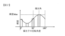
- FIG. 2 is a diagram illustrating the relationship between brightness and polarization angle.
- FIG. 3 is a diagram illustrating an image sensor used in the imaging section in the polarization evaluation device of the present invention.
- FIG. 4 is a diagram for explaining a configuration example of the imaging section in the polarization evaluation device of the present invention.
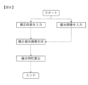
- FIG. 5 is a flowchart showing the operation of the correction coefficient calculating section.
- FIG. 6 is a flowchart showing the operation of the polarization characteristic evaluation section.
- FIG. 7 is a diagram for explaining the configuration of the polarization evaluation device used in Example 1 and Example 2.
- FIG. 1 is a diagram illustrating the configuration of a polarization evaluation apparatus according to the present invention.
- FIG. 2 is a diagram illustrating the relationship between brightness and polarization angle.
- FIG. 3 is a diagram illustrating an image sensor used in the imaging section in the polarization evaluation device
- FIG. 8 is a graph showing errors in polarization angles measured without correction of errors due to polarization characteristics of the optical system in Example 1.
- FIG. 9 is a graph showing errors in polarization angles measured by correcting errors due to polarization characteristics of the optical system in Example 1.
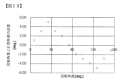
- FIG. 10 is a graph showing errors in polarization angles measured without correction of errors due to polarization characteristics of the optical system in Example 2.
- FIG. 11 is a graph showing errors in polarization angles measured by correcting errors due to polarization characteristics of the optical system in Example 2.
- FIG. 1 shows the configuration of a polarization evaluation device according to the present invention.
- the polarization evaluation device 1 includes an illumination unit 2 that irradiates observation illumination light onto an observation target 10, an imaging unit 3 that acquires polarized images in a plurality of specific directions from among reflected light from the observation target 10, and an imaging unit 3. It has an image processing unit 4 that outputs an image of the result of evaluating the polarization characteristics of the observation target 10 from the polarization images in a plurality of directions acquired in the above.
- the image processing unit 4 also includes a correction coefficient calculation unit 4a that calculates a correction coefficient for removing polarization noise based on polarization characteristics of an optical system other than the observation target 10, and a correction coefficient storage unit that stores the correction coefficient. 4b, and polarization for creating a corrected polarization image by removing the polarization noise from the polarization images in the plurality of directions based on the correction coefficients, and outputting a result of evaluating the polarization characteristics of the observation target 10 from the created correction polarization image. It has a characteristic evaluation section 4c.
- any image sensor, camera lens, or other equipment may be used as the imaging unit 3 in the polarization evaluation device 1.
- Any type of illumination may be used as the illumination unit 2 in the polarization evaluation device 1.
- the irradiation angle of the illumination light to the observation target 10 and the angle of incidence of light from the imaging surface to the image sensor may be arbitrarily set according to the evaluation target and the purpose of evaluation, and the present invention can be adjusted depending on the configuration of the optical system. Not limited.
- the imaging unit 3 is preferably configured to be able to acquire polarized images in three or more directions. This reason will be explained below.
- Measurement of polarization characteristics requires polarization images in multiple specific directions.
- the direction of polarization of the reflected light from the observation target 10 and the direction of the polarizer are different.
- the brightness of the captured image of the observation target 10 changes according to the relative phase. As shown in FIG. 2, this brightness change is represented by a sine wave with a period of 180°. Therefore, a sine wave that reproduces the relationship between polarizer direction and brightness of polarized images in multiple specific directions is found by fitting a sine wave equation with three variables: amplitude, phase, and offset.
- Polarization characteristics can be measured by defining the angle at which the brightness takes the maximum value in the sine wave as the polarization direction (polarization angle) of the reflected light from the observation target. At this time, it is preferable that the acquired polarization images in three directions include directions with a phase difference of 45° or more in order to maintain fitting accuracy.
- the imaging unit 3 has a configuration that can acquire polarized images in three or more directions.
- the imaging unit 3 may be configured to use an image sensor in which blocks in which polarizers having different polarization directions are arranged in pixels are arranged in an array.
- a block is made up of 2x2 pixels in which polarizers with different polarization directions (for example, 0°, 45°, 90°, and 135°) are arranged for each pixel, and multiple blocks are arranged.
- An example of image sensors arranged in an array is shown.
- the imaging unit 3 may have a configuration in which a rotatable polarizer 5 is arranged in front of the lens 3b, and the polarizer 5 is rotated by multiple angles to repeat imaging.
- FIG. 4 shows an example of the imaging section 3 having a configuration in which a rotatable polarizer 5 is arranged in front of the lens 3b.
- any image sensor or configuration may be used as long as it is capable of acquiring polarized images in three or more directions.
- the angle of incidence of light from the imaging surface of the imaging unit 3 to the image sensor may be arbitrarily arranged depending on the evaluation target and the purpose of the evaluation.
- the captured polarized images in multiple directions are output to the image processing unit 4. These polarization images are output to the correction coefficient calculation section 4a when used for creating correction coefficients, and to the polarization characteristic evaluation section 4c when used for measurement of polarization characteristics, depending on the purpose.
- the illumination unit 2 irradiates the observation target 10 with illumination light for observation.
- the polarization characteristics derived from the optical system are acquired in advance (for example, acquired for each pixel), a correction coefficient is created to remove this polarization noise, and only the polarization characteristics derived from the observation object 10 can be evaluated. , any type of lighting may be used.
- the irradiation angle of the illumination light with respect to the observation target 10 is not specified, and may be arbitrarily set and arranged according to the evaluation target and evaluation content. Furthermore, the illumination light is not particularly specified, and light of any wavelength may be used.
- the image processing unit 4 includes a correction coefficient calculation unit 4a that calculates a correction coefficient for removing polarization noise based on the polarization characteristics of an optical system other than the observation target 10, and a correction coefficient storage unit 4b that stores the correction coefficient. , a polarization characteristic evaluation unit 4c that creates a corrected polarization image by removing the polarization noise from the polarization images in the plurality of directions based on the correction coefficient, evaluates the polarization characteristics of the observation target from the corrected polarization image, and outputs the image; , has.
- a polarized image is input to the image processing unit 4 from the imaging unit 3.
- This polarization image can be input to the correction coefficient calculation unit 4a when used to calculate a correction coefficient for correcting polarization noise of the optical system, and to the polarization property evaluation unit 4c when used to evaluate the polarization characteristics of the observation target 10. .
- FIG. 5 shows a flowchart of the operation of the correction coefficient calculating section 4a.
- a plurality of polarization images in a specific direction which are captured as correction images to be described later, are input to the correction coefficient calculation unit 4a.
- the correction coefficient calculation unit 4a calculates the polarization characteristics (polarization angle, degree of polarization) of the observation target 10 for each pixel or block from the input polarization images in a plurality of specific directions. Then, a correction coefficient is calculated for each pixel and each block from the calculated polarization characteristics, and the calculated correction coefficient is output to the correction coefficient storage section 4b.
- the case where a correction coefficient is calculated and used for each pixel will be described below, but the same applies to the case where a correction coefficient is calculated and used for each block.
- Calculation of the correction coefficient only needs to be performed once for each configuration of the optical system, and by storing information on the calculated correction coefficient in the correction coefficient storage section 4b, it can be repeatedly used for subsequent evaluation of polarization characteristics.
- the correction image is an image of the correction observation target.
- the observation target for correction may be any target that can clarify the polarization direction of the polarization characteristics of the optical system and the ratio of polarization components (polarization) of the light incident on the imaging sensor.
- an object that clearly returns polarized light when reflecting the observation illumination light can be used as the correction observation object.
- the correction observation object is imaged while being rotated at a constant rotation angle. A plurality of polarized images may be used.
- a plurality of polarized images of a non-polarized object taken in a specific direction are used as polarized images for correction.
- an image captured of an object that exhibits uniform polarization characteristics regardless of location such as copy paper or a resin plate whose surface has been processed to provide non-polarized light. Let the amount of illumination light at this time be l.
- the obtained polarization images in a plurality of specific directions are obtained by fitting a sine wave that reproduces the relationship between the polarization direction ⁇ of the imaging unit 3 and the brightness I ⁇ for each pixel, and the brightness is the maximum in the sine wave obtained by fitting.
- the angle at which the value is taken is calculated for each pixel as the polarization direction (polarization angle) of the reflected light from the observation target.
- polarization angle may be calculated from the fitting, and the result may be applied to each pixel within the block.
- the polarization angle is may be calculated.
- the intensity of the polarization component contained in the reflected light is calculated for each pixel as the polarization degree k by the calculation formula shown in (Formula 2). .
- the average brightness A of the reflected light is calculated for each pixel by the calculation formula shown in (Formula 3).
- a plurality of polarization images in specific directions are similarly acquired for the observation target.
- the amount of illumination light during imaging at this time is assumed to be l'. This is determined by fitting a sine wave that reproduces the relationship between the polarization direction and brightness for each pixel to the acquired polarization images in a specific direction. For the waveform obtained by fitting, the average brightness A' of the reflected light is calculated for each pixel using the calculation formula (Equation 4).
- the average brightness A'' of the reflected light from the observation target is calculated by normalizing the light intensity l of the illumination light when imaging a non-polarized object and the light intensity l' of the illumination light when imaging the observation target, as ( Calculated using formula 5).
- the degree of polarization k' for each pixel of the polarized light possessed by the optical system included when the observation target is imaged is calculated using the calculation formula (Formula 6).
- the polarization angle ⁇ and polarization degree k' of the polarized light possessed by the optical system are calculated for each pixel, and correction information for correcting this polarization noise is calculated for each pixel, and the correction information storage unit 4b Output to.
- the amount of light that enters the image sensor depends on its angular component, the phase difference between the polarizer in the imaging unit, and the intensity of the polarized component. Change.
- the correction coefficient is determined by the phase difference between the polarization degree k ' of the polarized light possessed by the optical system, the direction ⁇ i of the polarizer of the imaging section constituting the optical system, and the polarization angle ⁇ of the polarized light possessed by the optical system.
- the correction coefficient s is calculated for each pixel according to (Equation 7).
- the calculated pixel correction coefficient s is output to the correction information storage section 4b.
- An image of an object whose reflected light shows polarization is captured as a polarization image for correction.
- a polarization image for correction For example, it is preferable to image an object whose reflected light clearly exhibits polarization, such as a resin plate with a hairline finish on its surface.
- Polarization images in a plurality of specific directions are captured with the object placed at a certain angle.
- the method for capturing the polarized images in the plurality of specific directions may be any method as long as the configuration is capable of acquiring polarized images in three or more directions.
- an image sensor in which blocks each having a polarizer having a different polarization direction in each pixel are arranged in an array may be used to obtain polarized images in a plurality of specific directions in one imaging operation.
- the imaging unit 3 may have a rotatable polarizer 5 disposed in front of the lens 3b, and the polarizer 5 may be rotated by multiple angles to repeatedly capture images.
- the polarization angle ⁇ is calculated from the calculation formula (Formula 1).
- the object is rotated, polarization images in a plurality of specific directions are similarly captured, and the polarization angle is calculated. Let the rotation angle of the object at this time be ⁇ . This operation is repeated while rotating the target by multiple angles, and the polarization angle calculation results are obtained for each rotation angle of the target.
- the brightness I ⁇ of the polarized image for each polarization direction ⁇ of each imaging unit includes the polarized light of the observation target and the polarized light of the optical system, so the brightness I ⁇ ' of the polarized light of the reflected light of the observation target can be calculated from (Equation 8). demand.
- k and ⁇ be variables representing the polarization degree and polarization angle of the optical system, respectively.
- the polarization angle ⁇ ' is recalculated from the calculation of (Equation 1) for each rotation angle of the object.
- a correction coefficient for correcting this polarization noise is calculated for each pixel according to (Equation 7) from the polarization angle ⁇ for each pixel and the polarization degree k for each pixel of the polarized light possessed by the optical system, and the correction information storage unit 4b Output to.
- the correction coefficient storage unit 4b stores correction coefficients for removing the polarization characteristics of the optical system for each pixel, which are calculated in advance by the correction coefficient calculation unit 4a. At the time of polarization characteristic evaluation, the correction coefficient information stored in the correction coefficient storage section 4b is output to the polarization characteristic evaluation section 4c.
- FIG. 6 shows a flowchart of the operation of the polarization characteristic evaluation section 4c.
- a plurality of polarization images in specific directions obtained from the imaging section 3 of the optical system are input to the polarization characteristic evaluation section 4c. Further, correction coefficient information for each pixel stored in the correction coefficient storage section 4b is input.
- a corrected polarized image is created by integrating the correction coefficient of the polarization direction and pixel position of the corresponding imaging unit 3 obtained from the correction coefficient storage unit 4b with respect to the brightness value of each pixel of the input polarized image. .
- arbitrary polarization information is calculated using the corrected polarization image and the result is output.
- the calculation result may be output as an image so that it can be visually understood.
- the polarization information to be calculated may be any information as long as it can be calculated from a plurality of polarization images.
- the angle at which the brightness takes the maximum value in the sine wave obtained by fitting can be calculated as the polarization angle.
- the degree of polarization ratio of polarized light components included
- Example 1 Using the optical system shown in FIG. 7, we implemented a technique for correcting errors due to the polarization characteristics of the optical system.
- the imaging unit 3 used an image sensor in which blocks in which polarizers of 0°, 45°, 90°, and 135° were arranged in each pixel were arranged in an array. Further, for the illumination unit 2, coaxial epi-illumination having a half mirror was used.
- FIG. 8 shows the rotation angle of the fine rotation stage 6 before correcting the error due to the polarization characteristics of the optical system described above, and the error in the measured polarization angle.
- a measurement error of up to ⁇ 5° occurs. From this, it can be seen that in the configuration of this optical system, there are factors that reduce measurement accuracy in the optical system itself. This is thought to be because the light is polarized when passing through the half mirror of the illumination section, and the illumination light has polarization characteristics.
- a correction image was obtained using a resin plate whose surface was matted to make it non-polarized.
- the correction coefficient s was calculated for each pixel by the method shown in the above-mentioned [first form of correction coefficient creation], and a correction coefficient distribution was created.
- FIG. 9 shows the relationship between the rotation angle of the fine rotation stage after correcting the error due to the polarization characteristics of the optical system described above and the error in the measured polarization angle.
- the maximum angular measurement error of ⁇ 5° can be reduced to a maximum of ⁇ 1°.
- Example 2 As in Example 1, using the optical system shown in FIG. 7, a resin plate (observation object 10) with hairline processing on the surface, whose reflected light shows polarization, was placed on the fine rotation stage 6 and rotated in 15° increments from 0 to 180. Images were taken while rotating the camera up to 10°.
- FIG. 10 shows the rotation angle of the fine rotation stage 6 before correcting the error caused by the polarization characteristics of the optical system, and the error in the measured polarization angle. As shown in FIG. 10, in the case of measurement without correction, a measurement error of up to ⁇ 5° occurs.
- correction coefficient s was calculated for each pixel using the method shown in the above-mentioned [Second form of correction coefficient creation], and a correction coefficient distribution was created.
- FIG. 11 shows the relationship between the rotation angle of the fine rotation stage after correcting the error caused by the polarization characteristics that the optical system waits for, and the error in the measured polarization angle.
- the maximum angle measurement error was ⁇ 5° (see Figure 10), but the maximum angle measurement error was ⁇ 1.2°. It can be seen that the reduction has been achieved.
- a correction coefficient is created from the polarization characteristics of the optical system acquired in advance, and the polarization characteristics of the optical system are applied to the polarization image taken of the observation target using the correction coefficient. Correction processing is performed. Therefore, it becomes possible to obtain a polarization image that represents only the polarization characteristics of the observation target, and it becomes possible to accurately evaluate the polarization characteristics of the observation target. Therefore, the present invention is particularly suitable for use in equipment that performs highly accurate fiber orientation recognition, for example.
- Polarization evaluation device 2 Illumination 3 Imaging unit 3a Camera 3b Lens 4 Image processing unit 4a Correction coefficient calculation unit 4b Correction coefficient storage unit 4c Polarization characteristic evaluation unit 5 Polarizer 6 Fine rotation stage 10 Observation target
Landscapes
- Physics & Mathematics (AREA)
- General Physics & Mathematics (AREA)
- Health & Medical Sciences (AREA)
- Life Sciences & Earth Sciences (AREA)
- Chemical & Material Sciences (AREA)
- Analytical Chemistry (AREA)
- Biochemistry (AREA)
- General Health & Medical Sciences (AREA)
- Immunology (AREA)
- Pathology (AREA)
- Spectroscopy & Molecular Physics (AREA)
- Investigating Or Analysing Materials By Optical Means (AREA)
Priority Applications (2)
| Application Number | Priority Date | Filing Date | Title |
|---|---|---|---|
| JP2022575756A JPWO2023171058A1 (https=) | 2022-03-08 | 2022-12-06 | |
| EP22931029.7A EP4492020A4 (en) | 2022-03-08 | 2022-12-06 | POLARIZATION ASSESSMENT DEVICE |
Applications Claiming Priority (2)
| Application Number | Priority Date | Filing Date | Title |
|---|---|---|---|
| JP2022034965 | 2022-03-08 | ||
| JP2022-034965 | 2022-03-08 |
Publications (1)
| Publication Number | Publication Date |
|---|---|
| WO2023171058A1 true WO2023171058A1 (ja) | 2023-09-14 |
Family
ID=87936499
Family Applications (1)
| Application Number | Title | Priority Date | Filing Date |
|---|---|---|---|
| PCT/JP2022/044844 Ceased WO2023171058A1 (ja) | 2022-03-08 | 2022-12-06 | 偏光評価装置 |
Country Status (3)
| Country | Link |
|---|---|
| EP (1) | EP4492020A4 (https=) |
| JP (1) | JPWO2023171058A1 (https=) |
| WO (1) | WO2023171058A1 (https=) |
Cited By (2)
| Publication number | Priority date | Publication date | Assignee | Title |
|---|---|---|---|---|
| US20240404035A1 (en) * | 2021-10-08 | 2024-12-05 | Tiama | Optical-computing device and method for analysing light passing through a container made of transparent or translucent material by means of a digital polarimetric camera |
| WO2025079431A1 (ja) * | 2023-10-13 | 2025-04-17 | ソニーグループ株式会社 | 画像処理装置 |
Citations (6)
| Publication number | Priority date | Publication date | Assignee | Title |
|---|---|---|---|---|
| JP2005337785A (ja) * | 2004-05-25 | 2005-12-08 | Dainippon Screen Mfg Co Ltd | エリプソメータ、偏光状態取得方法および光強度取得方法 |
| JP2015537211A (ja) * | 2012-11-15 | 2015-12-24 | フラウンホーファー−ゲゼルシャフト・ツール・フェルデルング・デル・アンゲヴァンテン・フォルシュング・アインゲトラーゲネル・フェライン | 炭素繊維材料の繊維方向の測定および炭素繊維複合構造での物体の製造 |
| JP2018044865A (ja) | 2016-09-14 | 2018-03-22 | 国立大学法人宇都宮大学 | 光学機器のキャリブレーション法 |
| WO2019198287A1 (ja) * | 2018-04-09 | 2019-10-17 | ソニー株式会社 | 情報処理装置と情報処理方法とプログラムおよびキャリブレーション装置 |
| JP2020080366A (ja) | 2018-11-13 | 2020-05-28 | ソニーセミコンダクタソリューションズ株式会社 | 受光装置 |
| CN112417370A (zh) * | 2020-11-12 | 2021-02-26 | 南京航空航天大学 | 粗糙表面物质的穆勒琼斯矩阵估计及偏振噪声分析方法 |
Family Cites Families (2)
| Publication number | Priority date | Publication date | Assignee | Title |
|---|---|---|---|---|
| WO2017099253A1 (ja) * | 2015-12-11 | 2017-06-15 | 株式会社ニコン | 偏光特性画像計測装置、偏光特性画像計測方法 |
| EP3580546A1 (en) * | 2017-02-08 | 2019-12-18 | Yissum Research Development Company of The Hebrew University of Jerusalem Ltd. | System and method for use in high spatial resolution ellipsometry |
-
2022
- 2022-12-06 EP EP22931029.7A patent/EP4492020A4/en active Pending
- 2022-12-06 JP JP2022575756A patent/JPWO2023171058A1/ja active Pending
- 2022-12-06 WO PCT/JP2022/044844 patent/WO2023171058A1/ja not_active Ceased
Patent Citations (7)
| Publication number | Priority date | Publication date | Assignee | Title |
|---|---|---|---|---|
| JP2005337785A (ja) * | 2004-05-25 | 2005-12-08 | Dainippon Screen Mfg Co Ltd | エリプソメータ、偏光状態取得方法および光強度取得方法 |
| JP2015537211A (ja) * | 2012-11-15 | 2015-12-24 | フラウンホーファー−ゲゼルシャフト・ツール・フェルデルング・デル・アンゲヴァンテン・フォルシュング・アインゲトラーゲネル・フェライン | 炭素繊維材料の繊維方向の測定および炭素繊維複合構造での物体の製造 |
| JP6328130B2 (ja) | 2012-11-15 | 2018-05-23 | フラウンホーファー−ゲゼルシャフト・ツール・フェルデルング・デル・アンゲヴァンテン・フォルシュング・アインゲトラーゲネル・フェライン | 炭素繊維材料の繊維方向の測定および炭素繊維複合構造での物体の製造 |
| JP2018044865A (ja) | 2016-09-14 | 2018-03-22 | 国立大学法人宇都宮大学 | 光学機器のキャリブレーション法 |
| WO2019198287A1 (ja) * | 2018-04-09 | 2019-10-17 | ソニー株式会社 | 情報処理装置と情報処理方法とプログラムおよびキャリブレーション装置 |
| JP2020080366A (ja) | 2018-11-13 | 2020-05-28 | ソニーセミコンダクタソリューションズ株式会社 | 受光装置 |
| CN112417370A (zh) * | 2020-11-12 | 2021-02-26 | 南京航空航天大学 | 粗糙表面物质的穆勒琼斯矩阵估计及偏振噪声分析方法 |
Non-Patent Citations (2)
| Title |
|---|
| LANE CONNOR, RODE DAVID, RÖSGEN THOMAS: "Calibration of a polarization image sensor and investigation of influencing factors", APPLIED OPTICS, OPTICAL SOCIETY OF AMERICA, US, vol. 61, no. 6, 20 February 2022 (2022-02-20), US , pages C37 - C45, XP093090820, ISSN: 1559-128X, DOI: 10.1364/AO.437391 * |
| See also references of EP4492020A4 |
Cited By (2)
| Publication number | Priority date | Publication date | Assignee | Title |
|---|---|---|---|---|
| US20240404035A1 (en) * | 2021-10-08 | 2024-12-05 | Tiama | Optical-computing device and method for analysing light passing through a container made of transparent or translucent material by means of a digital polarimetric camera |
| WO2025079431A1 (ja) * | 2023-10-13 | 2025-04-17 | ソニーグループ株式会社 | 画像処理装置 |
Also Published As
| Publication number | Publication date |
|---|---|
| EP4492020A1 (en) | 2025-01-15 |
| EP4492020A4 (en) | 2026-02-25 |
| JPWO2023171058A1 (https=) | 2023-09-14 |
Similar Documents
| Publication | Publication Date | Title |
|---|---|---|
| US6229913B1 (en) | Apparatus and methods for determining the three-dimensional shape of an object using active illumination and relative blurring in two-images due to defocus | |
| CN110099267B (zh) | 梯形校正系统、方法以及投影仪 | |
| CN115876124A (zh) | 基于偏振结构光相机的高反光表面三维重建方法及装置 | |
| CN103383249B (zh) | 灰度条纹投影光强非线性校正方法及基于该方法的相位校正方法 | |
| Zhao et al. | Calibration for stereo vision system based on phase matching and bundle adjustment algorithm | |
| WO2023171058A1 (ja) | 偏光評価装置 | |
| CN103994732B (zh) | 一种基于条纹投影的三维测量方法 | |
| CN102095387A (zh) | 基于偏振光分束成像的旋光角度场探测装置及其测量方法 | |
| US12222282B2 (en) | Semiconductor measurement apparatus | |
| JP6679366B2 (ja) | 光学装置および撮像装置 | |
| JP2010071878A (ja) | 感度調整方法、偏光計測方法、及び偏光計測装置 | |
| CN115451820B (zh) | 三通道偏振信息采集系统 | |
| CN109324063B (zh) | 偏振膜的摄像装置、检查装置以及检查方法 | |
| Zhu et al. | Three-dimensional measurement of fringe projection based on the camera response function of the polarization system | |
| CN111426382A (zh) | 一种多光谱成像系统及方法 | |
| CN105872403A (zh) | Mueller矩阵成像的动态范围扩展装置与方法 | |
| CN120580366A (zh) | 强环境光滤除和退偏振误差校正的三维重构方法及其系统 | |
| CN118265896A (zh) | 基于角度相关透射率确定光的波前斜率 | |
| CN115690185B (zh) | 一种融合偏振三维形状和偏振调制测距的深度重建方法 | |
| CN111487201A (zh) | 一种偏振图像信息的表征方法和表征参数的计算方法 | |
| TWI413765B (zh) | 物質特性量測方法與系統 | |
| TW200925587A (en) | Surface examining device | |
| CN113192146B (zh) | 一种基于深度学习消除栅线投影相移技术中离焦误差的方法 | |
| Ma et al. | Systematical and universal calibration scheme for division-of-aperture polarimetric camera | |
| JP4552202B2 (ja) | 表面検査装置 |
Legal Events
| Date | Code | Title | Description |
|---|---|---|---|
| WWE | Wipo information: entry into national phase |
Ref document number: 2022575756 Country of ref document: JP |
|
| 121 | Ep: the epo has been informed by wipo that ep was designated in this application |
Ref document number: 22931029 Country of ref document: EP Kind code of ref document: A1 |
|
| WWE | Wipo information: entry into national phase |
Ref document number: 2022931029 Country of ref document: EP |
|
| NENP | Non-entry into the national phase |
Ref country code: DE |
|
| ENP | Entry into the national phase |
Ref document number: 2022931029 Country of ref document: EP Effective date: 20241008 |