WO2023171001A1 - プレス加工装置 - Google Patents
プレス加工装置 Download PDFInfo
- Publication number
- WO2023171001A1 WO2023171001A1 PCT/JP2022/032413 JP2022032413W WO2023171001A1 WO 2023171001 A1 WO2023171001 A1 WO 2023171001A1 JP 2022032413 W JP2022032413 W JP 2022032413W WO 2023171001 A1 WO2023171001 A1 WO 2023171001A1
- Authority
- WO
- WIPO (PCT)
- Prior art keywords
- punch
- load
- waveform
- press
- punching
- Prior art date
- Legal status (The legal status is an assumption and is not a legal conclusion. Google has not performed a legal analysis and makes no representation as to the accuracy of the status listed.)
- Ceased
Links
Images







Classifications
-
- B—PERFORMING OPERATIONS; TRANSPORTING
- B21—MECHANICAL METAL-WORKING WITHOUT ESSENTIALLY REMOVING MATERIAL; PUNCHING METAL
- B21D—WORKING OR PROCESSING OF SHEET METAL OR METAL TUBES, RODS OR PROFILES WITHOUT ESSENTIALLY REMOVING MATERIAL; PUNCHING METAL
- B21D28/00—Shaping by press-cutting; Perforating
-
- B—PERFORMING OPERATIONS; TRANSPORTING
- B21—MECHANICAL METAL-WORKING WITHOUT ESSENTIALLY REMOVING MATERIAL; PUNCHING METAL
- B21D—WORKING OR PROCESSING OF SHEET METAL OR METAL TUBES, RODS OR PROFILES WITHOUT ESSENTIALLY REMOVING MATERIAL; PUNCHING METAL
- B21D37/00—Tools as parts of machines covered by this subclass
-
- B—PERFORMING OPERATIONS; TRANSPORTING
- B30—PRESSES
- B30B—PRESSES IN GENERAL
- B30B15/00—Details of, or accessories for, presses; Auxiliary measures in connection with pressing
- B30B15/28—Arrangements for preventing distortion of, or damage to, presses or parts thereof
Definitions
- the present disclosure relates to a press processing device.
- the punching characteristic measuring device described in Patent Document 1 measures the punching force during punching by converting the temporal change in deformation of the frame during punching into an electrical signal.
- the punching characteristic measuring device described in Patent Document 1 has room for improvement in terms of improving the accuracy of calculating the wear amount of the tool.
- the present disclosure provides a press processing device that can improve the accuracy of calculating the wear amount of a punch.
- a press processing apparatus includes: A press processing device that performs punching on a workpiece, a punch that moves in a pressing direction and has a pressing surface facing the workpiece and a side surface connecting to the pressing surface; a die having a hollow portion into which the punch is inserted and on which the work is placed; a sensor that detects the load applied to the punch; comprising a control unit that controls the punch, the die, and the sensor;
- the control unit includes: Generating a load waveform indicating the relationship between the load and time from a start time to an end time of punching based on the load detected by the sensor, The wear amount of the punch is calculated based on the maximum value of the load in the load waveform and the change in time until the maximum value of the load is reached.
- FIG. 1 A schematic diagram showing a press processing apparatus according to Embodiment 1 of the present disclosure
- FIG. 1 A schematic diagram showing the bottom dead center state of the punch in the press processing device shown in Figure 1.
- Top view showing the sensor of the press processing device in Figure 1 A flowchart illustrating the process of determining whether punch polishing is necessary in a press processing device.
- Schematic diagram showing the process of punching a workpiece using a press machine Schematic diagram showing the process of punching a workpiece using a press machine
- Schematic diagram showing the process of punching a workpiece using a press machine Schematic diagram showing the process of punching a workpiece using a press machine
- Graph showing the load waveform generated based on the load detected by each of the four sensors A graph that superimposes the load waveform when punch wear progresses on the load waveform in Figure 6.
- a graph showing an example of the relationship between the impulse of a punch and the amount of first wear on the pressing surface of the punch A graph showing an example of the relationship between the maximum load of the stable waveform part and the second wear amount of the side surface of the punch 1 in the second period
- Press processing which punches out a plate-shaped work, generally involves pressing the work loaded on a die with a stripper, then pushing a part of the work into the die with a punch and punching it out to obtain a predetermined shape. This is a technology that can be used. Press processing by punching is generally used in a wide variety of fields such as home appliances, precision machinery, and automobile parts.
- a punching characteristic measurement device that measures the punching force during punching by converting temporal changes in frame deformation during punching into an electrical signal, such as the punching characteristic measuring device described in Patent Document 1. Measuring devices are known.
- the punching characteristic measuring device described in Patent Document 1 converts frame deformation during punching into an electrical signal and measures the punching force during punching.
- Punching force is the resistance force when punching a laminate with a die. As the die wears, the punching force increases. Therefore, it is being considered to use the punching force to calculate the wear state of the die and determine whether or not the tool needs to be re-polished.
- Patent Document 1 detects the deformation of the frame at a position further away from the machining position of the mold, and therefore cannot calculate the wear state of the mold with high accuracy. There is a problem.
- the present inventors have studied a press processing device that can accurately calculate the wear amount of a punch, and have arrived at the following invention.
- the press processing apparatus includes: A press processing device that performs punching on a workpiece, a punch that moves in a pressing direction and has a pressing surface facing the workpiece and a side surface connecting to the pressing surface; a die having a hollow portion into which the punch is inserted and on which the workpiece is placed; a sensor that detects the load applied to the punch; comprising a control unit that controls the punch, the die, and the sensor;
- the control unit includes: Generating a load waveform indicating the relationship between the load and time from the start to the end of punching based on the load detected by the sensor, The wear amount of the punch is calculated based on the maximum value of the load in the load waveform and the change in time until the maximum value of the load is reached.
- the control unit includes: Calculating a first amount of wear on the press surface of the punch based on a waveform of the load waveform in a first period from the start of the punching process until the minimum time when the load reaches the minimum value after reaching the maximum value of the load. death, A second wear amount of the side surface of the punch may be calculated based on a waveform of a second period from the minimum time to the end of the punching process in the load waveform.
- the control unit may calculate an impulse applied to the punch in the first period based on the load waveform, and calculate the first wear amount based on the calculated impulse.
- the load waveform has, in the second period, a vibration waveform part in which the load changes, and a stable waveform part following the vibration waveform part and in which the load changes less than in the vibration waveform part,
- the control unit may calculate the second wear amount based on the maximum load of the stable waveform portion.
- the control unit includes: It may be determined that the press surface of the punch is to be polished when the first wear amount is larger than a predetermined first threshold value.
- the control unit includes: When the second wear amount is larger than a predetermined second threshold value, it may be determined that the side surface of the punch is to be polished.
- the first threshold may be greater than the second threshold.
- the sensor may include a plurality of sensors that detect the load.
- the press processing apparatus includes: moreover, a gap sensor that detects the position of the punch; may be provided.
- FIG. 1 is a schematic diagram showing a press processing apparatus 100 according to Embodiment 1 of the present disclosure.
- FIG. 2 is a schematic diagram showing the bottom dead center state of the punch 1 in the press working apparatus 100 of FIG. 1.
- FIG. 3 is a top view showing the sensor 6 of the press processing apparatus 100 of FIG. 1. Note that some components are omitted from illustration in FIGS. 2 and 3.
- a press processing apparatus 100 according to the present embodiment will be described with reference to FIGS. 1 to 3.
- the XYZ coordinate system shown in each figure is for facilitating understanding of the embodiment, and does not limit the embodiment.
- the X direction is the width direction of the press working apparatus 100
- the Y direction is the depth direction of the press working apparatus 100
- the Z direction is the height direction of the press working apparatus 100.
- the press processing apparatus 100 is an apparatus that includes a punch 1, a die 2, a sensor 6, and a control section 18, and performs a punching process on a plate-shaped work 5.
- the press processing device 100 is, for example, a servo screw press device that can be controlled with high precision.
- the press processing apparatus 100 includes a press apparatus main body 9 and a control section 18.
- the press apparatus main body 9 includes a punch 1, a die 2, and a sensor 6.
- the press apparatus main body 9 of the press processing apparatus 100 has an upper mold including a punch 1 attached to a slide 7, and a lower mold including a die 2 attached to a bolster 8.
- the press device main body 9 rotates a ball screw 12 connected to a servo motor 11 based on a command from a control unit 18 to move the slide 7 along a shaft 10 at a predetermined speed in the press direction (Z direction). Drive it up and down.
- the press apparatus main body 9 By such an operation of the press apparatus main body 9, the workpiece 5 can be punched.
- the punch 1 is a tool that moves in the press direction (Z direction) to punch out the workpiece 5.
- the punch 1 has a press surface 1a facing the workpiece 5 and a side surface 1b connected to the press surface 1a.
- the punch 1 is attached to a slide 7 together with a stripper plate 3 that presses the work 5 against the die 2 during punching. As the slide 7 moves, the punch 1 is pressed against the workpiece 5 and punching is performed.
- the punch 1 has a circular pressing surface 1a. Therefore, the workpiece 5 can be punched out into a circular shape.
- the punch 1 is formed into a cylindrical shape having a circular pressing surface 1a with a diameter of 4.5 mm, and punches a round hole into the workpiece 5.
- the punch 1 is made of, for example, a superhard material.
- Superhard materials include W (tungsten), Cr (chromium), Mo (molybdenum), Ti (titanium), Zr (zirconium), Hf (hafnium), V (vanadium), Nb (niobium), and Ta (tantalum).
- a superhard material refers to an extremely hard alloy.
- the carbide material for example, an alloy corresponding to VM-40 of the Cemented Carbide Tools Association Standard (CIS) can be used.
- a workpiece 5 is placed on the die 2 during punching.
- the die 2 is formed with a hollow portion 2a into which the punch 1 is inserted.
- the hollow portion 2a is a through hole that penetrates the die 2 in the Z direction.
- the die 2 is attached to a bolster 8 together with a die plate 4 for holding the die 2.
- the die 2 is made of, for example, a superhard material.
- the workpiece 5 is a plate-shaped material to be processed by the press processing device 100.
- a plurality of works 5 are transported in the X direction or Y direction by a transport section (not shown) in accordance with the pressing operation of the press apparatus main body 9, and are sequentially punched.
- the workpiece 5 is made of SUS301-EH material, which is a steel type classified as austenitic stainless steel.
- the SUS301-EH material is, for example, a material used as a mainspring or spring for automobile parts.
- the thickness of the workpiece 5 is 0.031 mm
- the hardness is 529 HV
- the tensile strength is 1,679 N/mm 2 .
- the sensor 6 is a load sensor that detects the load applied to the punch 1.
- the sensor 6 detects the load applied to the punch 1 in the pressing direction (Z direction).
- the sensor 6 detects the load applied to the punch 1 in the pressing direction (Z direction) when punching the workpiece 5.
- the reaction force P (see FIG. 2) of the punch 1 in the press direction (Z direction) when punching the workpiece 5 is detected.
- the senor 6 includes four sensors 6a to 6d. Further, in this embodiment, the sensor 6a and the sensor 6b are arranged symmetrically in the Y direction, and the sensor 6c and the sensor 6d are arranged symmetrically in the X direction. In this embodiment, four sensors 6a to 6d are arranged concentrically. By arranging the four sensors 6a to 6d in this manner, it becomes easier to determine which part of the punch 1 is worn out.
- the control unit 18 controls the punch 1, die 2, and sensor 6.
- the control section 18 includes a press controller 14 , a sensor controller 15 , a calculation section 16 , and a determination section 17 .
- the control unit 18 is configured by a digital circuit such as a microcomputer, CPU, MPU, GPU, DSP, FPGA, ASIC, or the like.
- the press controller 14 drives the servo motor 11 to rotate the ball screw 12, thereby driving the slide 7 up and down in the press direction (Z direction) at a predetermined speed.
- the sensor controller 15 is electrically connected to the sensor 6 of the punch 1 and the gap sensor 13 described below, and outputs the detected values of the respective sensors 6 and 13 to the calculation unit 16.
- the calculation unit 16 generates a load waveform indicating the relationship between the load applied to the punch 1 and time based on the load detected by the sensor 6, and calculates the amount of wear on the punch 1 based on the load waveform. When the punching process is repeated, the punch 1 gradually wears out. The calculation unit 16 calculates the amount of wear on the press surface 1a and side surface 1b of the punch 1. The generation of the load waveform and the calculation of the amount of wear will be described in detail later.
- the determination unit 17 determines whether polishing of the punch 1 is necessary based on the amount of wear on the press surface 1a and the side surface 1b calculated by the calculation unit 16. As the amount of wear on the punch 1 increases, the accuracy of the punching dimensions of the workpiece 5 gradually deteriorates. For this reason, it is preferable to polish the punch 1 at the timing when the amount of wear exceeds a predetermined threshold value.
- the determination unit 17 outputs a signal to the press controller 14 to interrupt the punching process. Upon receiving the notification, the press controller 14 stops the servo motor 11 and interrupts the punching process.
- the press processing apparatus 100 includes a gap sensor 13 that detects the position of the punch 1. More specifically, the gap sensor 13 can detect that the punch 1 shown in FIG. 2 is in the lowest possible position, that is, in the bottom dead center state. Furthermore, the gap sensor 13 can also detect how far the punch 1 has risen from the bottom dead center state.
- the gap sensor 13 can be configured, for example, by a displacement sensor that measures a minute distance between the object and the object in a non-contact manner.
- the gap sensor 13 is attached, for example, to an arbitrary position of the lower die of the press processing apparatus 100 including the die 2, the die plate 4, and the bolster 8, and is connected to the upper die including the punch 1, the stripper plate 3, and the slide 7. By detecting the contact, it is detected that the punch 1 is at the bottom dead center. Further, the gap sensor 13 can determine the start timing for detecting the load applied to the punch 1. Specifically, in order to start detecting the load applied to the punch 1 at the same timing for each punching shot, the start timing can be determined based on the gap of the gap sensor 13 and the position of the punch 1 from the bottom dead center state. can. In this way, the gap sensor 13 can be used as a trigger for detecting the load on the punch 1.
- gap sensors 13 are arranged at each of the four corners of the lower mold, it is possible to detect whether the upper mold and the lower mold are arranged in parallel.
- the gap sensor 13 is not an essential component, and the press processing apparatus 100 may not include the gap sensor 13.
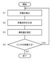
- FIG. 4 is a flowchart illustrating a process of determining whether polishing of the punch 1 is necessary in the press processing apparatus 100. Referring to FIG. 4, the determination of whether or not polishing of the punch 1 is necessary will be described.
- the sensor 6 detects the load applied to the punch 1 in the press direction (Z direction) (step S1).
- the load is detected by each of the four sensors 6a to 6d.
- the load detected by the sensor 6 is output to the calculation unit 16 via the sensor controller 15 of the control unit 18.
- the calculation unit 16 generates a load waveform indicating the relationship between the load applied to the punch 1 and time (step S2).
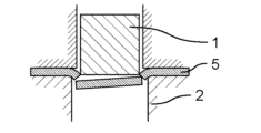
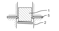
- FIG. 5A to 5D are schematic diagrams showing the process of punching the workpiece 5 using the press processing apparatus 100.
- FIG. 6 is a graph in which load waveforms generated based on the loads detected by each of the four sensors 6a to 6d are superimposed. The load waveform will be described with reference to FIGS. 5A to 6. Note that the broken line in FIG. 7 shows the load waveform when the punch 1 is hardly worn.
- the punch 1 descends from the top dead center state in the Z direction, and the punch 1 comes into contact with the workpiece 5 (FIG. 5A).
- the top dead center state refers to a state in which the punch 1 is at the highest possible position.
- time C1 is when the punch 1 comes into contact with the workpiece 5 and the load applied to the punch 1 becomes greater than 0.
- the punch 1 comes into contact with the workpiece 5
- the punch 1 starts punching the workpiece 5, as shown in FIG. 5B. Therefore, a load starts to be applied to the punch 1 from time C1, and the load on the punch 1 increases rapidly, and the load reaches the maximum value P0 at time m1. Thereafter, as shown in FIG.
- the load applied to the punch 1 decreases to around 0 and becomes a minimum value.
- the point in time when the load applied to the punch 1 reaches a value close to 0 is time C2 (minimum time) in FIG.
- the minimum time C2 refers to the time point when the load on the punch 1 drops to around 0 within a predetermined period after the load on the punch 1 reaches the maximum value P0.
- the reason why the load applied to the punch 1 decreases to around 0 is because the punch 1 punches out the workpiece 5 and the resistance to the punch 1 becomes small. Note that even when the workpiece 5 is cut, the load applied to the punch 1 detected by the sensor 6 may not reach zero due to vibration of the punch 1 or other external factors.
- the punch 1 and the die 2 come into contact and a load is applied to the punch 1 due to interference between the punch 1 and the die 2 or a disturbance element caused by the workpiece 5.
- the punch 1 or the die 2 may be tilted, causing the punch 1 and the die 2 to come into contact with each other, causing a load to be applied to the punch 1.
- the workpiece 5 after cutting may be drawn between the punch 1 and the die 2 (see FIG. 5D), so that a load may be applied to the punch 1.
- the load applied to the punch 1 becomes zero.
- the time point when the load applied to the punch 1 becomes 0 is time C3 in FIG.
- step S2 the calculation unit 16 generates a load waveform, and then the calculation unit 16 calculates the wear amount of the punch 1 (step S3).
- the amount of wear on the punch 1 is calculated based on the respective load waveforms shown in FIG.
- time C1 In the period from the start time of the punching process (time C1) until the minimum time C2 when the load reaches its minimum value after reaching the maximum value P0, that is, the period until the punch 1 contacts the workpiece 5 and the workpiece 5 is cut.
- a load is mainly applied to the pressing surface 1a of the punch 1.
- the period from the start of the punching process until the minimum time C2 when the load reaches the maximum value P0 and reaches the minimum value is the first period T0, and the amount of wear on the press surface 1a of the punch 1 is the first period in the load waveform. Calculated based on the waveform of T0.
- time C3 During the period from the minimum time C2 to the end time of the punching process (time C3), that is, from the time the workpiece 5 is cut until the load applied to the punch becomes 0, the load is mainly applied to the side surface 1b of the punch 1. It takes.
- the period from the minimum time C2 to the end of the punching process (time C3) is the second period Ts0.
- Ts0 a load is applied to the side surface 1b of the punch 1 due to interference between the punch 1 and the die 2 or because the workpiece 5 after cutting is drawn between the punch 1 and the die 2. As shown in FIG.
- the load waveform has an oscillating waveform part where the load changes, and a stable waveform part following the oscillating waveform part and having a smaller change in load than the oscillating waveform part.
- the amount of wear on the side surface 1b of the punch 1 is calculated based on the waveform of the second period in the load waveform. Note that in the stable waveform part, the change in load is smaller than in the vibration waveform part means that in the stable waveform part, the change in load per predetermined time is smaller than in the vibration waveform part.
- the sensors 6a to 6d are fixed to the punch 1 shown in FIG. 2, and gaps are formed between the sensors 6a to 6d and the plate 19.
- the loads applied to the sensors 6a to 6d become close to zero.
- the sensors 6a to 6d collide with or move away from the plate 19 due to the reaction from punching out the workpiece 5.
- the load detected at this time appears in the vibration waveform section.
- the punch 1 comes to the bottom dead center state while the workpiece 5 and the side surface 1b of the punch 1 are in contact with each other.
- the load detected at this time appears in the stable waveform portion.
- FIG. 7 is a graph in which the load waveform when the wear of the punch 1 in FIG. 6 has not progressed is superimposed on the load waveform when the wear of the punch 1 has progressed.
- the maximum load applied to the punch 1 increases from the maximum value P0 to the maximum value P1. Further, as the wear of the punch 1 progresses, the minimum time shifts from time C2 to time C4. Therefore, as the wear of the punch 1 progresses, the maximum load applied to the punch 1 increases from the maximum value P0 to the maximum value P1. This is longer than the first period T0 of the load waveform when there is no wear.
- the second period in the load waveform changes from period Ts0 to period Ts1.
- the length of the second period becomes shorter. That is, the period Ts1 is shorter than the period Ts0.
- the maximum load of the punch 1 in the stable waveform portion increases from the maximum value Ps0 to the maximum value Ps1.
- the wear amount of the punch 1 includes the first wear amount of the press surface 1a of the punch 1 and the second wear amount of the side surface 1b of the punch 1, and in this embodiment, the first wear amount of the press surface 1a and the second wear amount of the side surface 1b of the punch 1. and a second wear amount of the side surface 1b.
- the first wear amount of the press surface 1a of the punch 1 can be calculated based on the impulse of the punch 1 in the first periods T0 and T1.
- the impulse of the punch 1 is the product of the load applied to the punch 1 and time, and is expressed by the area of the load waveform in the first periods T0 and T1. That is, impulse can be calculated based on the load waveform.
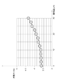
- FIG. 8 is a graph showing an example of the relationship between the impulse D of the punch 1 and the first wear amount a of the press surface 1a of the punch 1. From equation (1) and FIG. 8, for example, when the impulse of the punch 1 is 4 Nms, it can be calculated that the first wear amount a of the press surface 1a of the punch 1 is 23 ⁇ m.
- the second wear amount of the side surface 1b of the punch 1 can be calculated based on the maximum loads Ps0 and Ps1 of the stable waveform portion in the second period Ts0 and Ts1.
- FIG. 9 is a graph showing an example of the relationship between the maximum load Ps of the stable waveform portion and the second wear amount b of the side surface 1b of the punch 1 during the second periods Ts0 and Ts1. From equation (2) and FIG. 9, for example, when the maximum load Ps is 130N, it can be calculated that the second wear amount b of the side surface 1b of the punch 1 is 1.25 ⁇ m.
- the calculation unit 16 calculates the first wear amount a of the press surface 1a based on the impulse of the punch 1 in the first period T0 in the load waveform, and calculates the stable waveform in the second period Ts0 in the load waveform.
- a second wear amount b of the side surface 1b is calculated based on the maximum load Ps of the portion.
- press working apparatus 100 has four sensors 6a to 6d, and four load waveforms shown in FIG. 6 are generated. Therefore, the calculated values of the first wear amount a and the second wear amount b are calculated for each of the four load waveforms.
- the workpieces 5 tend to be cut by fracture rather than shearing, and the load on the press surface 1a of the punch 1 increases. Therefore, as the punching process is repeated, the impulse of the first period T0 of the load waveform increases significantly. Therefore, in the multilayer punching process, the first wear amount a can be calculated with higher accuracy based on the change in the impulse during the first period T0 of the load waveform.
- step S3 when the calculation unit 16 calculates the wear amount of the punch 1 (step S3), the determination unit 17 determines whether polishing of the punch 1 is necessary (step S4).
- the determination unit 17 determines whether polishing of the punch 1 is necessary based on whether the first wear amount a of the press surface 1a and the second wear amount b of the side surface 1b each exceed a threshold value.
- the determination unit 17 determines that the punch 1 is to be polished when the first wear amount a is larger than a predetermined first threshold value or when the second wear amount b is larger than a predetermined second threshold value (step S4). Yes). In this embodiment, if at least one of the first wear amounts a for each of the four load waveforms is larger than the first threshold value, or at least one of the second wear amounts b for each of the four load waveforms is larger than the second threshold value. If it is larger, the determination unit 17 determines that the punch 1 should be polished.
- the first amount of wear on the press surface 1a was 23 ⁇ m
- the second amount of wear on the side surface 1b was 1.25 ⁇ m. Therefore, if the allowable range of the burr size is 5 ⁇ m, the maximum allowable first wear amount a is 23 ⁇ m, and the maximum allowable second wear amount b is 1.25 ⁇ m. I can do it. Therefore, the first threshold in this case is 23 ⁇ m and the second threshold is 1.25 ⁇ m.
- the maximum values of the first wear amount a and the second wear amount b are determined by the allowable burr size, the material of the workpiece 5 or the punch 1 and the die 2, the punching speed or the press It is determined in advance based on processing conditions such as the presence or absence of oil.
- the press surface 1a of the punch 1 generally wears faster than the side surface 1b of the punch 1. This is because the load applied to the pressing surface 1a of the punch 1 is greater than that applied to the side surface 1b during punching.
- the maximum load P0 in the first period T0 is larger than the maximum load Ps0 in the stable waveform part in the second period Ts0, so the load applied to the press surface 1a is applied to the side surface 1b. It can be seen that it is larger than the load. Therefore, the first threshold value is set to a larger value than the second threshold value.
- step S4 the press controller 14 stops the driving of the press processing apparatus 100, interrupts the punching process, and performs the process of determining whether or not the punch 1 needs to be polished. ends. If the determining unit 17 determines that the punch 1 is not to be polished (No in step S4), the punching process continues and the process returns to step S1.
- step S4 when any one or more of the first wear amounts a calculated from the load waveforms from the four sensors 6a to 6d exceeds the first threshold, the punching process is interrupted. Similarly, when any one or more of the second wear amounts b calculated from the load waveforms from the four sensors 6a to 6d exceeds the second threshold, the punching process is interrupted.
- the load applied to the punch 1 is detected by the sensor 6.
- a load waveform is generated based on the detected load.
- the load waveform has a first period T0 in which the load is mainly applied to the press surface 1a of the punch 1, and a second period Ts0 in which the load is mainly applied to the side surface 1b of the punch 1.
- the wear amount of the punch 1 is calculated based on the maximum value of the load in the load waveform and the change in time until the maximum value of the load is reached.
- the first wear amount a of the press surface 1a of the punch 1 is calculated based on the waveform of the first period T0
- the second wear amount a of the side surface 1b of the punch 1 is calculated based on the waveform of the second period Ts0. Calculate the wear amount b. In this way, since the amount of wear on the press surface 1a and the side surface 1b can be calculated from the load waveform, the amount of wear on the punch 1 can be calculated with high accuracy.
- the necessity of polishing the punch is determined based on the first wear amount a and the second wear amount b of the punch 1, the accuracy of determining whether polishing is necessary can be improved.
- the material of the workpiece 5 is SUS301-EH material has been described, but the material is not limited to this.
- the workpiece 5 can be made of various metal materials.
- the present invention is not limited to this.
- the number of sensors may be one or more.
- the punch 1 has a circular press surface 1a, but the present invention is not limited to this.
- the shape of the press surface 1a is not limited to a circle, but can be any shape such as a polygon or an ellipse.
- the press processing device of the present disclosure is useful as a device for punching any workpiece used for home appliances, medical equipment, etc.
Landscapes
- Engineering & Computer Science (AREA)
- Mechanical Engineering (AREA)
- Punching Or Piercing (AREA)
Priority Applications (2)
| Application Number | Priority Date | Filing Date | Title |
|---|---|---|---|
| JP2024505872A JPWO2023171001A1 (https=) | 2022-03-10 | 2022-08-29 | |
| CN202280093110.XA CN118742402A (zh) | 2022-03-10 | 2022-08-29 | 冲压加工装置 |
Applications Claiming Priority (2)
| Application Number | Priority Date | Filing Date | Title |
|---|---|---|---|
| JP2022037447 | 2022-03-10 | ||
| JP2022-037447 | 2022-03-10 |
Publications (1)
| Publication Number | Publication Date |
|---|---|
| WO2023171001A1 true WO2023171001A1 (ja) | 2023-09-14 |
Family
ID=87936426
Family Applications (1)
| Application Number | Title | Priority Date | Filing Date |
|---|---|---|---|
| PCT/JP2022/032413 Ceased WO2023171001A1 (ja) | 2022-03-10 | 2022-08-29 | プレス加工装置 |
Country Status (3)
| Country | Link |
|---|---|
| JP (1) | JPWO2023171001A1 (https=) |
| CN (1) | CN118742402A (https=) |
| WO (1) | WO2023171001A1 (https=) |
Cited By (2)
| Publication number | Priority date | Publication date | Assignee | Title |
|---|---|---|---|---|
| WO2025084035A1 (ja) * | 2023-10-20 | 2025-04-24 | パナソニックIpマネジメント株式会社 | 情報処理装置及び情報処理方法 |
| WO2025094577A1 (ja) * | 2023-11-02 | 2025-05-08 | パナソニックIpマネジメント株式会社 | 打抜き加工制御方法 |
Citations (5)
| Publication number | Priority date | Publication date | Assignee | Title |
|---|---|---|---|---|
| JPH0234229A (ja) * | 1988-07-22 | 1990-02-05 | Furukawa Electric Co Ltd:The | 打抜き成形不良検出方法 |
| JPH05212455A (ja) * | 1992-02-03 | 1993-08-24 | Amada Co Ltd | プレス金型の寿命検出方法および装置 |
| JP2010279990A (ja) * | 2009-06-08 | 2010-12-16 | Nec Corp | プレス加工機および速度制御方法 |
| JP2017209698A (ja) * | 2016-05-24 | 2017-11-30 | 日本デイトンプログレス株式会社 | プレス装置及びそれに使用されるバッキングプレート |
| JP2019126823A (ja) * | 2018-01-24 | 2019-08-01 | 株式会社Kmc | プレス製造条件収集システムおよびプレス成形機用センサープレート |
-
2022
- 2022-08-29 CN CN202280093110.XA patent/CN118742402A/zh active Pending
- 2022-08-29 JP JP2024505872A patent/JPWO2023171001A1/ja active Pending
- 2022-08-29 WO PCT/JP2022/032413 patent/WO2023171001A1/ja not_active Ceased
Patent Citations (5)
| Publication number | Priority date | Publication date | Assignee | Title |
|---|---|---|---|---|
| JPH0234229A (ja) * | 1988-07-22 | 1990-02-05 | Furukawa Electric Co Ltd:The | 打抜き成形不良検出方法 |
| JPH05212455A (ja) * | 1992-02-03 | 1993-08-24 | Amada Co Ltd | プレス金型の寿命検出方法および装置 |
| JP2010279990A (ja) * | 2009-06-08 | 2010-12-16 | Nec Corp | プレス加工機および速度制御方法 |
| JP2017209698A (ja) * | 2016-05-24 | 2017-11-30 | 日本デイトンプログレス株式会社 | プレス装置及びそれに使用されるバッキングプレート |
| JP2019126823A (ja) * | 2018-01-24 | 2019-08-01 | 株式会社Kmc | プレス製造条件収集システムおよびプレス成形機用センサープレート |
Cited By (2)
| Publication number | Priority date | Publication date | Assignee | Title |
|---|---|---|---|---|
| WO2025084035A1 (ja) * | 2023-10-20 | 2025-04-24 | パナソニックIpマネジメント株式会社 | 情報処理装置及び情報処理方法 |
| WO2025094577A1 (ja) * | 2023-11-02 | 2025-05-08 | パナソニックIpマネジメント株式会社 | 打抜き加工制御方法 |
Also Published As
| Publication number | Publication date |
|---|---|
| JPWO2023171001A1 (https=) | 2023-09-14 |
| CN118742402A (zh) | 2024-10-01 |
Similar Documents
| Publication | Publication Date | Title |
|---|---|---|
| WO2023171001A1 (ja) | プレス加工装置 | |
| JP6803161B2 (ja) | 金型の異常予測システム、それを備えたプレス機及び金型の異常予測方法 | |
| JP2009078300A (ja) | 大幅に滑らかな切断面と拡大された機能面を備える打抜き部材を製造する方法と装置 | |
| JP7695536B2 (ja) | せん断加工装置及びせん断加工方法 | |
| WO2017079085A1 (en) | Ribbon bonding tools, and methods of designing ribbon bonding tools | |
| Li et al. | Micromilling of thin ribs with high aspect ratios | |
| CN101918158B (zh) | 制造具有多个突出部的金属部件的方法 | |
| JP7808773B2 (ja) | プレス加工装置 | |
| EP4470691A1 (en) | Method for performing shearing work on amorphous alloy foil | |
| US20260124663A1 (en) | Press working apparatus | |
| WO2024241789A1 (ja) | プレス加工装置 | |
| Çavuşoğlu | An investigation of punch radius and clearance effects on the sheet metal blanking process | |
| Kuhfuss et al. | Electromagnetic linked micro part processing | |
| Kudla | Deformations and strength of miniature drills | |
| JPWO2023171001A5 (https=) | ||
| Cardoso et al. | Micro milling of metallic materials-a brief overview | |
| JP5966118B2 (ja) | 金属材の加工方法及び金属材の加工装置 | |
| JP2012171028A (ja) | スクエアエンドミル | |
| JP2007098523A (ja) | ブローチの寿命判断方法、ブローチ品質管理装置、及びブローチ加工装置 | |
| JP3530019B2 (ja) | 振動プレス加工方法および振動プレス金型 | |
| JP6888472B2 (ja) | 剪断加工方法 | |
| US20260124662A1 (en) | Press-molding device | |
| EP4400244A1 (en) | Friction stir welding tool member, friction stir welding device, and friction stir welding method | |
| WO2016056435A1 (ja) | 鍛造方法および鍛造装置 | |
| CN108421837A (zh) | 监测成型工具上的成形齿布置的功能状态的方法和装置 |
Legal Events
| Date | Code | Title | Description |
|---|---|---|---|
| 121 | Ep: the epo has been informed by wipo that ep was designated in this application |
Ref document number: 22930978 Country of ref document: EP Kind code of ref document: A1 |
|
| ENP | Entry into the national phase |
Ref document number: 2024505872 Country of ref document: JP Kind code of ref document: A |
|
| WWE | Wipo information: entry into national phase |
Ref document number: 202280093110.X Country of ref document: CN |
|
| NENP | Non-entry into the national phase |
Ref country code: DE |
|
| 122 | Ep: pct application non-entry in european phase |
Ref document number: 22930978 Country of ref document: EP Kind code of ref document: A1 |