WO2023170761A1 - レーザ加工システム、及びレーザ加工方法 - Google Patents
レーザ加工システム、及びレーザ加工方法 Download PDFInfo
- Publication number
- WO2023170761A1 WO2023170761A1 PCT/JP2022/009809 JP2022009809W WO2023170761A1 WO 2023170761 A1 WO2023170761 A1 WO 2023170761A1 JP 2022009809 W JP2022009809 W JP 2022009809W WO 2023170761 A1 WO2023170761 A1 WO 2023170761A1
- Authority
- WO
- WIPO (PCT)
- Prior art keywords
- laser
- robot
- control device
- laser beam
- operation mode
- Prior art date
- Legal status (The legal status is an assumption and is not a legal conclusion. Google has not performed a legal analysis and makes no representation as to the accuracy of the status listed.)
- Ceased
Links
Images







Classifications
-
- B—PERFORMING OPERATIONS; TRANSPORTING
- B23—MACHINE TOOLS; METAL-WORKING NOT OTHERWISE PROVIDED FOR
- B23K—SOLDERING OR UNSOLDERING; WELDING; CLADDING OR PLATING BY SOLDERING OR WELDING; CUTTING BY APPLYING HEAT LOCALLY, e.g. FLAME CUTTING; WORKING BY LASER BEAM
- B23K26/00—Working by laser beam, e.g. welding, cutting or boring
- B23K26/08—Devices involving relative movement between laser beam and workpiece
- B23K26/0869—Devices involving movement of the laser head in at least one axial direction
- B23K26/0876—Devices involving movement of the laser head in at least one axial direction in at least two axial directions
- B23K26/0884—Devices involving movement of the laser head in at least one axial direction in at least two axial directions in at least three axial directions, e.g. manipulators, robots
-
- B—PERFORMING OPERATIONS; TRANSPORTING
- B23—MACHINE TOOLS; METAL-WORKING NOT OTHERWISE PROVIDED FOR
- B23K—SOLDERING OR UNSOLDERING; WELDING; CLADDING OR PLATING BY SOLDERING OR WELDING; CUTTING BY APPLYING HEAT LOCALLY, e.g. FLAME CUTTING; WORKING BY LASER BEAM
- B23K26/00—Working by laser beam, e.g. welding, cutting or boring
- B23K26/08—Devices involving relative movement between laser beam and workpiece
- B23K26/0869—Devices involving movement of the laser head in at least one axial direction
- B23K26/0876—Devices involving movement of the laser head in at least one axial direction in at least two axial directions
-
- B—PERFORMING OPERATIONS; TRANSPORTING
- B25—HAND TOOLS; PORTABLE POWER-DRIVEN TOOLS; MANIPULATORS
- B25J—MANIPULATORS; CHAMBERS PROVIDED WITH MANIPULATION DEVICES
- B25J15/00—Gripping heads and other end effectors
- B25J15/04—Gripping heads and other end effectors with provision for the remote detachment or exchange of the head or parts thereof
- B25J15/0466—Gripping heads and other end effectors with provision for the remote detachment or exchange of the head or parts thereof with means for checking exchange completion
Definitions
- the present disclosure relates to a laser processing system and a laser processing method.
- a laser processing system for laser processing a workpiece is known (for example, Patent Document 1).
- laser processing may be performed in an automatic operation mode in which the robot and laser oscillator are automatically operated according to a processing program. In this case, it is required to ensure the safety of the operator.
- a laser processing system for laser processing a workpiece includes a laser emitting device that emits a laser beam generated by a laser oscillator, and a laser emitting device that is removably attached to the workpiece.
- a robot that moves the robot relatively, an attachment/detachment detection sensor that detects when the laser emitting device is attached to and detached from the robot, a laser beam emitting operation that operates a laser oscillator to emit laser light from the laser emitting device, and operates the robot. and a mode selection switch that selects an operation mode for laser processing.
- the mode selection switch selects an automatic operation mode in which the laser beam emission operation and movement operation are automatically executed according to the processing program as the operation mode, and the attachment/detachment detection sensor determines whether the laser emission device is attached to the robot. When detected, the laser beam emitting operation and the moving operation are executed as the automatic operation mode.
- the automatic operation of the laser processing system can be safely executed, so the safety of the operator can be ensured during the automatic operation.
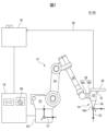
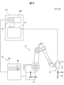
- FIG. 1 is a schematic diagram of a laser processing system according to an embodiment.
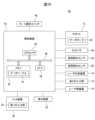
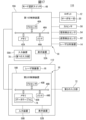
- FIG. 1 is a block diagram of a laser processing system according to an embodiment.
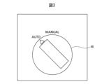
- 3 illustrates a mode selection switch according to one embodiment.
- the attachment/detachment detection sensor is shown as a contact type sensor. In the attachment/detachment detection sensor shown in FIG. 4, a state in which the laser emitting device is detached from the robot is shown.
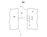
- the attachment/detachment detection sensor is shown as a non-contact type sensor.
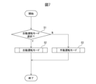
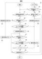
- 3 is a flowchart showing an example of a laser processing method executed by the laser processing system shown in FIG. 2.
- FIG. 8 is a flowchart showing an example of step S2 in FIG. 7.
- FIG. 8 is a flowchart showing an example of step S3 in FIG. 7.
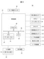
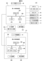
- FIG. 3 is a block diagram of a laser processing system according to another embodiment.
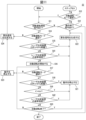
- 11 is a flowchart showing an example of step S2 in FIG. 7 executed by the laser processing system shown in FIG. 10. It is a schematic diagram of a laser processing system concerning yet another embodiment.
- 13 is a block diagram of the laser processing system shown in FIG. 12.
- FIG. 14 is a flowchart showing an example of step S2 in FIG. 7 executed by the laser processing system shown in FIG. 13.
- An example of a mode selection switch image is shown.
- It is a schematic diagram of a laser processing system concerning yet another embodiment.
- 17 is a block diagram of the laser processing system shown in FIG. 16.
- FIG. FIG. 3 is a block diagram of a laser processing system according to yet another embodiment.
- the laser processing system 10 is a system that can perform laser processing (laser welding, laser cutting, etc.) on a workpiece (not shown) in cooperation with an operator.
- the laser processing system 10 includes a robot 12, a laser emission device 14, a laser oscillator 16, and a control device 18.
- the robot 12 moves the laser emitting device 14 relative to the workpiece.
- the robot 12 is a vertically articulated robot and includes a robot base 20, a rotating trunk 22, a lower arm 24, an upper arm 26, and a wrist 28.
- the robot base 20 is fixed on the floor of the work cell.
- the turning trunk 22 is provided on the robot base 20 so as to be able to turn around a vertical axis.
- the lower arm portion 24 is provided on the rotating trunk 22 so as to be rotatable around a horizontal axis.
- the upper arm section 26 is rotatably provided at the distal end of the lower arm section 24.
- the wrist portion 28 includes a wrist base 28a provided at the distal end of the upper arm portion 26 so as to be rotatable around two axes orthogonal to each other, and a wrist flange 28b rotatably provided on the wrist base 28a. and has.
- Each component of the robot 12 (that is, the robot base 20, the rotating trunk 22, the lower arm 24, the upper arm 26, and the wrist 28) is provided with a plurality of servo motors 30 (FIG. 2), respectively.
- These servo motors 30 move each movable component of the robot 12 (that is, the rotating trunk 22, the lower arm section 24, the upper arm section 26, the wrist section 28, and the wrist flange 28b) around the drive shaft in response to commands from the control device 18. Rotate it. Thereby, the robot 12 moves the laser emitting device 14 relative to the workpiece.
- the laser emitting device 14 is removably attached to the wrist flange 28b of the robot 12, and emits the laser beam LB generated by the laser oscillator 16.
- the laser emitting device 14 is a laser processing head, and includes a head body 32, a nozzle 34, and a grip part 36.
- the head body 32 is hollow, and includes an optical lens (collimating lens, focus lens, etc.) and a lens drive unit (for example, a servo motor) that displaces the optical lens according to a command from the control device 18. ) and other optical system components.
- the nozzle 34 is hollow and provided at the tip of the head body 32.
- the nozzle 34 has a truncated conical outer shape whose cross-sectional area decreases from the base end to the tip end, and an exit port 34a is formed at the tip end.
- a hollow chamber is formed inside the nozzle 34 and the head main body 32, and assist gas is supplied into the chamber from an assist gas supply device (not shown) provided outside.
- the laser beam LB generated by the laser oscillator 16 propagates within the chamber and is emitted from the emission port 34a together with the assist gas.
- the gripping portion 36 is provided at the base end of the head body 32 so that the operator can grip it with one hand.
- the grip portion 36 may have a recess corresponding to the fingers of one hand so that the operator can easily grip it with one hand.
- the operator can carry the laser emitting device 14 by grasping the gripping portion 36 and removing the laser emitting device 14 from the wrist flange 28b.
- the laser oscillator 16 internally oscillates a laser in response to a command CM1 (laser power command, etc.) from the control device 18, and generates a laser beam LB.
- the laser oscillator 16 may be of any type, such as a fiber laser oscillator, a CO 2 laser oscillator, or a solid state laser (YAG laser) oscillator.
- the laser oscillator 16 supplies the generated laser beam LB to the laser emitting device 14 via the light guide path 38.
- the light guide path 38 is composed of an optical fiber, a cavity, a light guide material such as crystal, a reflecting mirror, an optical lens, or the like.
- the control device 18 performs a laser beam emission operation LO in which the laser oscillator 16 is operated to emit the laser beam LB from the laser emission device 14, and a movement operation in which the robot 12 is operated and the laser emission device 14 is moved relative to the workpiece.
- Control MO is a computer having a processor 40, memory 42, and I/O interface 44.
- the processor 40 has a CPU, a GPU, etc., is communicably connected to a memory 42 and an I/O interface 44 via a bus 46, and performs various calculations for executing laser processing described below while communicating with these components. Perform processing.
- the memory 42 has a RAM, a ROM, or the like, and temporarily or permanently stores various data used in the arithmetic processing executed by the processor 40 and various data generated during the arithmetic processing.
- the I/O interface 44 has, for example, an Ethernet (registered trademark) port, a USB port, an optical fiber connector, or an HDMI (registered trademark) terminal, and allows data to be exchanged with an external device under instructions from the processor 40. Communicate by wire or wirelessly.
- the robot 12 (servo motor 30), the laser emitting device 14 (lens driving section), and the laser oscillator 16 are communicably connected to the I/O interface 44.
- a robot coordinate system C1 is set for the robot 12.
- the robot coordinate system C1 is a coordinate system for automatically controlling the operation of each movable component of the robot 12.
- the robot coordinate system C1 is arranged on the robot base 20 such that its origin is located at the center of the robot base 20 and its z-axis is parallel to the rotation axis (i.e., vertical direction) of the rotation trunk 22. It is fixed and set for.
- a tool coordinate system C2 is set in the laser emitting device 14.
- the tool coordinate system C2 is a coordinate system for automatically controlling the position of the laser emitting device 14 in the robot coordinate system C1, and defines the position of the laser emitting device 14 in the robot coordinate system C1.
- position may mean position and posture.
- the tool coordinate system C2 has its origin (so-called TCP) located at the center of the emission port 34a of the laser emission device 14, and its z-axis coincides with the optical axis of the emitted laser beam LB. They are set with respect to the laser emitting device 14 so that they are parallel (specifically, coincident).
- the position of the laser emitting device 14 is expressed as coordinates Q (X, Y, Z, W, P, R) of the tool coordinate system C2 in the robot coordinate system C1.
- the coordinates (X, Y, Z) indicate the position of the laser emitting device 14 in the robot coordinate system C1 (that is, the origin of the tool coordinate system C2)
- the coordinates (W, P, R) indicate the position of the robot coordinate system C1.
- the orientation OR that is, the direction of each axis of the tool coordinate system C2) of the laser emitting device 14 in the coordinate system C1 is shown (so-called yaw, pitch, roll).
- the control device 18 When moving the laser emitting device 14, the control device 18 sets the tool coordinate system C2 in the robot coordinate system C1, and moves the robot so that the laser emitting device 14 is positioned at the position represented by the set tool coordinate system C2.
- a command CM2 position command, speed command, torque command, etc.
- the control device 18 can operate the robot 12 and position the laser emitting device 14 at an arbitrary position in the robot coordinate system C1.
- the control device 18 is provided with a mode selection switch 48.
- the mode selection switch 48 is for selecting the operation mode DM of laser processing to be executed by the control device 18. As shown in FIG. 3, in this embodiment, the mode selection switch 48 selects the driving mode DM between an automatic driving mode DM1 represented as "AUTO" and a manual driving mode DM2 represented as "MANUAL". It is configured so that it can be switched between.
- the automatic operation mode DM1 is an operation mode DM in which the control device 18 automatically executes the laser beam emission operation LO and the movement operation MO according to a processing program PG created in advance.
- the control device 18 sequentially generates a command CM1 to the laser oscillator 16 and a command CM2 to the robot 12 (servo motor 30) according to the machining program PG, and according to the commands CM1 and CM2,
- the laser oscillator 16 and robot 12 are automatically operated.
- the machining program PG may include a first machining program PG1 that defines the operation of the laser oscillator 16 and a second machining program PG2 that defines the operation of the robot 12.
- the machining program PG (PG1, PG2) is stored in the memory 42 in advance.
- the operator grasps and carries the laser emitting device 14 with his/her hand, causes the control device 18 to manually execute the laser beam emitting operation LO, and uses the laser beam LB emitted from the laser emitting device 14.
- the operator manually gives a manual emission command CM3, which will be described later, to the control device 18, and the control device 18 executes the laser beam emission operation LO in response to the manual emission command CM3.
- FIG. 3 shows a state in which the automatic driving mode DM1 (“AUTO”) is selected by the mode selection switch 48.
- the mode selection switch 48 supplies an automatic operation mode transition command CM4 to the control device 18.
- the mode selection switch 48 supplies a manual operation mode transition command CM5 to the control device 18.
- the automatic operation mode transition command CM4 and the manual operation mode transition command CM5 may be ON/OFF signals (for example, automatic operation mode transition command CM4: ON signal, manual operation mode transition command CM5: OFF signal).
- the control device 18 is further provided with an input device 50 and a display device 52.
- the input device 50 has a keyboard, a mouse, a touch panel, or the like, and receives data input from an operator.
- the display device 52 has a liquid crystal display, an organic EL display, or the like, and displays various data.
- the input device 50 and the display device 52 are connected to the I/O interface 44 so that they can communicate by wire or wirelessly.
- the input device 50 and the display device 52 may be integrated into the casing of the control device 18, or may be provided separately from the casing of the control device 18, for example as one computer (PC, etc.). may be provided.
- the laser processing system 10 further includes an attachment/detachment detection sensor 54 and a force sensor 56.
- the attachment/detachment detection sensor 54 detects attachment/detachment of the laser emitting device 14 to/from the robot 12 .
- the attachment/detachment detection sensor 54 is electrically conductive when the laser emitting device 14 is attached to the wrist flange 28b, and becomes non-conductive when the laser emitting device 14 is detached from the wrist flange 28b, thereby emitting the laser beam. It includes a contact sensor that detects attachment and detachment of the device 14 to and from the wrist flange 28b.
- FIGS. 4 and 5 An example of the attachment/detachment detection sensor 54 as such a contact type sensor is shown in FIGS. 4 and 5.
- the attachment/detachment detection sensor 54 is built into the outer wall of the head body 32, and includes a pair of terminals 58 and 60, a resistance detection sensor 62, and a pair of terminals 58 and 60 and the resistance detection sensor 62. It has a conducting wire 64 that electrically connects the two.
- the terminals 58 and 60 are made of a conductive material (iron, copper, etc.) and are arranged facing each other so as to be exposed to a space defined inside the hole 32a formed in the outer wall of the head body 32. There is.
- the resistance detection sensor 62 is connected to the I/O interface 44 of the control device 18 and detects the resistance R between the terminals 58 and 60 by applying a voltage between the terminals 58 and 60.
- the wrist flange 28b is provided with a projection 28c that projects outward from the outer surface of the wrist flange 28b.
- the protrusion 28c is made of a conductive material (iron, copper, etc.).
- the terminals 58 and 60 become non-conductive, and the resistance R between the terminals 58 and 60 increases significantly (R ⁇ ).
- the resistance detection sensor 62 detects a resistance R that changes as the laser emitting device 14 is attached to and detached from the wrist flange 28b, and based on the resistance R, detects whether the laser emitting device 14 is attached to and detached from the wrist flange 28b.
- the resistance detection sensor 62 sends a detachment signal Sd( For example, an OFF or "0" signal) is transmitted to the control device 18.
- the resistance detection sensor 62 transmits the detection data Dr of the resistance R to the control device 18, and the processor 40 of the control device 18 determines whether R>R th . Dislodgement of device 14 may also be detected.
- the contact-type attachment/detachment detection sensor 54 shown in FIGS. 4 and 5 detects attachment/detachment of the laser emitting device 14 to/from the wrist flange 28b by coming into contact with the protrusion 28c as a member of the robot 12. According to such a contact sensor, detachment of the laser emitting device 14 from the wrist flange 28b can be detected more reliably.
- the pair of terminals 58 and 60 may be provided at a position closer to the bottom 32c than the opening 32b of the hole 32a.
- the attachment/detachment detection sensor 54 can detect even a slight detachment (displacement) of the laser emitting device 14 from the wrist flange 28b.
- the attachment/detachment detection sensor 54 may be built into the wrist flange 28b. In this case, a hole 32a is formed in the wrist flange 28b, and a protrusion 28c is formed in the outer wall of the head body 32.
- the attachment/detachment detection sensor 54 may include a non-contact type sensor that detects attachment/detachment of the laser emitting device 14 to/from the wrist flange 28b in a non-contact manner.
- An example of the attachment/detachment detection sensor 54 as such a non-contact type sensor is shown in FIG.
- the attachment/detachment detection sensor 54 is built into the outer wall of the head main body 32, and includes a transmitter 66 and a receiver 68.
- the transmitter 66 transmits electromagnetic waves EW (for example, infrared rays) toward the wrist flange 28b.
- the electromagnetic wave EW emitted from the transmitter 66 is reflected on the outer surface of the wrist flange 28b.
- the receiving section 68 receives the electromagnetic wave EW reflected by the wrist flange 28b.
- the attachment/detachment detection sensor 54 shown in FIG. 6 detects attachment/detachment of the laser emitting device 14 to/from the wrist flange 28b in a non-contact manner according to the electromagnetic wave EW received by the receiving section 68.
- the receiving unit 68 when the receiving unit 68 does not detect the reflected electromagnetic wave EW, it transmits a detachment signal Sd indicating that the laser emitting device 14 has detached from the wrist flange 28b to the control device 18.
- the receiving unit 68 transmits the detection data De of the electromagnetic wave EW to the control device 18, and the processor 40 of the control device 18 detects detachment of the laser emitting device 14 based on the detection data De. Good too.
- the transmitting section 66 of the attachment/detachment detection sensor 54 may be provided on one of the wrist flange 28b and the head main body 32, and the receiving section 68 may be provided on the other of the wrist flange 28b and the head main body 32.
- the force sensor 56 detects the external force F applied to the robot 12 or the laser emitting device 14.
- the force sensor 56 includes a torque sensor that is built into each servo motor 30 of the robot 12 and detects the torque applied to the output shaft of the servo motor 30.
- the processor 40 of the control device 18 determines the magnitude and direction of the external force F applied to the robot 12 (for example, the upper arm 26 or the wrist 28) or the laser emitting device 14 from the detection data D ⁇ of each torque sensor.
- the region to which the external force F is applied (for example, the upper arm 26, the wrist 28, or the laser emitting device 14) can be detected.
- the force sensor 56 has a 6-axis force sensor.
- the 6-axis force sensor is built into a component of the robot 12 (for example, the robot base 20 or the wrist 28), and has a cylindrical main body and a plurality of strain gauges provided on the main body.
- the control device 18 can detect the magnitude and direction of the external force F applied to the robot 12 or the laser emitting device 14 and the region to which the external force F is applied from the detection data Df of each strain gauge.
- the force sensor 56 includes a current sensor that detects feedback current from each servo motor 30. Since this feedback current changes according to the torque applied to the servo motor 30, the control device 18 detects the external force F from the detection data Di (that is, the feedback current) of each current sensor, similarly to the torque sensor described above. can.
- FIG. 7 is started, for example, when the processor 40 of the control device 18 receives an operation start command (for example, a power ON command) from an operator, a computer program, or a higher-level controller.
- an operation start command for example, a power ON command
- step S1 the processor 40 determines whether the automatic driving mode DM1 has been selected by the mode selection switch 48. Specifically, the processor 40 determines whether the automatic driving mode transition command CM4 or the manual driving mode transition command CM5 has been received from the mode selection switch 48. When the processor 40 receives the automatic operation mode transition command CM4, the processor 40 determines YES and proceeds to step S2, whereas when it receives the manual operation mode transition instruction CM5, the processor 40 determines NO and proceeds to step S3.
- step S2 the processor 40 shifts the operation mode DM to the automatic driving mode DM1.
- the operation flow in automatic driving mode DM1 in step S2 will be described below with reference to FIG.
- step S11 the processor 40 determines whether or not it has received an automatic driving start command CM6 that causes the control device 18 to start automatic driving in the automatic driving mode DM1.
- the processor 40 generates an automatic driving start image (not shown) in which a button image for starting automatic driving is displayed, and displays it on the display device 52.
- the operator can input the automatic operation start command CM6 to the control device 18 by operating the input device 50 and clicking the button image displayed on the automatic operation start image.
- the input device 50 functions as the first input unit 70 (FIG. 1) that receives the input of the automatic driving start command CM6 that causes the control device 18 to start the automatic driving mode DM1.
- the processor 40 receives the automatic operation start command CM6, it determines YES and proceeds to step S14, whereas when it determines NO, it proceeds to step S12.
- step S12 the processor 40 determines whether or not the operation end command CM7 (for example, a shutdown command) has been received. For example, the operator operates the input device 50 to input the operation end command CM7.
- the processor 40 receives the operation end command CM7, it determines YES and ends the flow of step S2 shown in FIG. 8, thereby ending the flow shown in FIG. 7.
- the processor 40 determines NO, the process proceeds to step S13.
- step S13 the processor 40 determines whether the automatic driving mode DM1 is still selected by the mode selection switch 48. If the processor 40 determines YES, the process returns to step S11, whereas if the processor 40 determines NO (that is, the mode selection switch 48 has been switched to the manual operation mode DM2), the process proceeds to step S3 in FIG.
- step S14 the processor 40 determines whether the automatic driving mode DM1 is still selected by the mode selection switch 48, similarly to step S13. If the processor 40 determines YES, the process proceeds to step S15, whereas if the processor 40 determines NO, the process proceeds to step S24.
- step S15 the processor 40 determines whether the laser emitting device 14 has detached from the robot 12 (specifically, the wrist flange 28b). Specifically, the processor 40 determines whether the detachment of the laser emitting device 14 from the robot 12 has been detected by the attachment/detachment detection sensor 54 based on the detachment signal Sd or the detection data Dr or De. judge. The processor 40 determines YES if detachment of the laser emitting device 14 from the robot 12 is detected and proceeds to step S22, while determining NO if attachment of the laser emitting device 14 to the robot 12 is detected. After making a determination, the process proceeds to step S16.
- step S16 the processor 40 starts automatic operation. Specifically, the processor 40 sequentially generates a command CM1 to the laser oscillator 16 and a command CM2 to the robot 12 according to the processing program PG, and automatically executes the laser beam emission operation LO and the movement operation MO. Start driving.
- step S17 the processor 40 determines whether the automatic driving mode DM1 is still selected by the mode selection switch 48, as in step S14 described above. If the processor 40 determines YES, the process proceeds to step S18, whereas if the processor 40 determines NO, the process proceeds to step S23.
- step S18 the processor 40 determines whether the laser emitting device 14 has detached from the robot 12, similar to step S15 described above. If the processor 40 determines YES, the process proceeds to step S21, whereas if the processor 40 determines NO, the process proceeds to step S19.
- step S19 the processor 40 determines whether the external force F detected by the force sensor 56 exceeds a predetermined threshold F th (F>F th ). If the processor 40 determines that F>F th , the processor 40 determines YES and proceeds to step S21, whereas if the processor 40 determines NO, the process proceeds to step S20.
- F th a predetermined threshold
- the processor 40 detects an external force applied to a specific portion of the robot 12 and the laser emitting device 14 (for example, the wrist portion 28 or the laser emitting device 14) based on the detection data D ⁇ , Df, or Di of the force sensor 56.
- F1 may be monitored and the determination may be YES if the external force F1 exceeds the threshold value F1 th (F1>F1 th ).
- step S20 the processor 40 determines whether automatic driving has ended. For example, the processor 40 can determine from the processing program PG to be executed whether all the laser beam emitting operations LO and movement operations MO specified in the processing program PG have been completed. If the processor 40 determines YES, the process proceeds to step S12, whereas if the processor 40 determines NO, the process returns to step S17. In this way, the processor 40 repeatedly executes the loop of steps S17 to S20 until it determines YES in steps S18, S19, or S20, and executes the laser beam emitting operation LO and the movement operation MO in the automatic operation mode DM1.
- the processor 40 stops at least one of the laser beam emitting operation LO and the moving operation MO in step S21.
- the processor 40 may stop both the laser beam emitting operation LO and the moving operation MO in this step S21.
- the processor 40 stops the operation of the servo motors 30 by stopping commands (torque commands, etc.) to each servo motor 30 of the robot 12, thereby stopping the movement operation MO.
- the processor 40 forcibly stops the operation of each servo motor 30 by activating each brake mechanism, Therefore, the moving operation MO may be stopped.
- the processor 40 stops the laser light output operation LO by stopping the laser light generation operation of the laser oscillator 16.
- the processor 40 blocks the laser beam LB with the shutter, thereby controlling the laser beam output operation LO. may be stopped.
- step S21 after determining YES in step S18 the processor 40 continues the moving operation MO while stopping the laser beam emitting operation LO, and in step S21 after determining YES in step S19. In this case, both the laser beam emitting operation LO and the moving operation MO may be stopped.
- the robot 12 is a collaborative robot that can stop its operation in response to the external force F detected by the force sensor 56.
- the determination in step S18 is YES, the safety of the operator can be ensured by stopping only the laser beam emitting operation LO.
- step S21 after determining YES in step S18, the processor 40 continues the movement operation MO while stopping the laser beam emitting operation LO, and in step S21 after determining YES in step S19.
- the moving operation MO may be stopped while the laser beam emitting operation LO may be continued. Even if it is determined YES in step S19, the safety of the operator can be ensured if the attitude OR of the laser emitting device 14 (that is, the emitting direction of the laser beam LB) does not change significantly.
- step S22 the processor 40 generates a warning signal AL.
- the processor 40 may issue a message saying, "The laser emitting device may have detached from the robot. Please check whether the laser emitting device is attached correctly." A visual or audio warning signal AL1 is generated.
- step S22 after determining YES in step S19, the processor 40 sends, for example, an image or audio warning message saying, "The robot may have interfered with an environmental object. Please check the surroundings of the robot.” Generate AL2.
- the processor 40 may display the generated warning signal AL1 or AL2 as an image on the display device 52, or may output it as a sound from a speaker (not shown) provided in the control device 18. After step S22, the processor 40 returns to step S12.
- step S23 the processor 40 stops at least one of the laser beam emitting operation LO and the moving operation MO, as in step S21 described above. For example, in step S23, the processor 40 stops both the laser beam emitting operation LO and the moving operation MO.
- step S24 the processor 40 generates a warning signal AL.
- the processor 40 generates a visual or audio warning signal AL3 that says "Automatic driving cannot be performed because the driving mode has been changed.”
- the processor 40 may display the generated warning signal AL3 on the display device 52 as an image or may output it as audio from a speaker.
- the processor 40 proceeds to step S3 in FIG.
- step S1 determines whether manual operation mode DM2 is selected by mode selection switch 48. If the determination in step S1 is NO (that is, manual operation mode DM2 is selected by mode selection switch 48), processor 40 changes operation mode DM to manual operation mode in step S3. Move to DM2.
- the operation flow in manual operation mode DM2 in step S3 will be described below with reference to FIG.
- step S31 processor 40 determines whether manual ejection command CM3 has been received.
- the laser processing system 10 further includes a second input section 72 (FIGS. 1 and 2) that receives the input of the manual emission command CM3.
- the second input unit 72 has a push button, a switch, a touch panel, or the like, and is communicably connected to the I/O interface 44 of the control device 18.
- the second input section 72 is provided adjacent to the grip part 36 of the laser emitting device 14 so that an input operation can be performed with one hand of the operator who grips the grip part 36 of the laser emitting device 14. It is provided.
- the operator can input the manual ejection command CM3 to the control device 18 by operating the second input section 72 with the fingers of one hand holding the grip section 36.
- the second input unit 72 transmits a manual ejection command CM3 (for example, an ON or "1" signal) to the control device 18.
- CM3 for example, an ON or "1" signal
- the processor 40 determines YES and proceeds to step S32, whereas if the processor 40 determines NO, the process proceeds to step S35.
- step S32 the processor 40 executes the laser beam emission operation LO in the manual operation mode DM2 in response to the manual emission command CM3 received through the second input unit 72.
- the workpiece machining conditions C P in the manual operation mode DM2 and the output conditions C O of the laser beam LB emitted in the laser beam emitting operation LO of the manual operation mode DM2 are associated with each other.
- a data table 74 (FIG. 2) stored in advance is stored in the memory 42 in advance.
- the processing conditions CP include, for example, the material of the workpiece (SUS, aluminum, etc.), the thickness [mm], and the melting point [° C.].
- the output condition C O includes, for example, the laser power [kW], duty ratio [%], and pulse oscillation frequency [Hz] of the laser beam LB.
- the data table 74 stores output conditions C O (laser power, duty ratio, pulse oscillation frequency) in association with each of a plurality of processing conditions C P (material, thickness, melting point).
- the processor 40 presets the output condition CO in the manual operation mode DM2. As an example, the operator may manually select the output condition C O corresponding to the machining condition C P (for example, material and thickness) of the workpiece to be machined from the data table 74 . In this case, processor 40 generates an image of data table 74 and displays it on display device 52 .
- the operator operates the input device 50 while viewing the image of the data table 74 to search and select the output condition C O corresponding to the machining condition C P of the workpiece to be machined from the data table 74 .
- the processor 40 receives operator input through the input device 50 and sets the output condition C O selected from the data table 74 as the output condition in the manual operation mode DM2.
- the operator may operate the input device 50 to input the processing conditions C P of the workpiece to be processed.
- the processor 40 automatically searches the data table 74 for the output condition C O corresponding to the machining condition C P input by the operator through the input device 50, and uses the searched output condition C O in the manual operation mode DM2. Set as an output condition in . In this manner, the processor 40 presets the output condition C O in the manual operation mode DM2 based on the data table 74.
- the processor 40 generates a command CM1 to the laser oscillator 16 according to the preset output condition C O in response to the manual emission command CM3, and generates a command CM1 for the laser oscillator 16 according to the output condition C O , and the laser power, duty ratio, and A laser beam generation operation LO is performed to generate a laser beam LB having a pulse oscillation frequency and a pulse oscillation frequency.
- the operator can emit the laser beam LB of the desired output condition C0 from the laser emitting device 14 held in one hand, and manually process the workpiece with the laser beam.
- step S33 the processor 40 determines whether the manual ejection command CM3 is continuously received from the second input unit 72 (for example, the signal of the manual ejection command CM3 is continuously ON or "1"). Determine whether The processor 40 loops step S33 while the determination is YES, and proceeds to step S34 if the determination is NO (that is, the signal of the manual ejection command CM3 is OFF or becomes "0"). . In this way, the processor 40 continues the laser beam generation operation LO in the manual operation mode DM2 until the determination in step S33 is NO.
- step S34 the processor 40 stops the laser light generation operation LO.
- the processor 40 may stop the laser light output operation LO by stopping the laser light generation operation of the laser oscillator 16 or by blocking the laser light LB with the above-mentioned shutter.
- step S35 the processor 40 determines whether or not the operation end command CM7 has been received, similar to step S12 described above. If the processor 40 determines YES, it ends the flow of step S3 shown in FIG. 9, and thus ends the flow shown in FIG. 7. On the other hand, if the processor 40 determines NO, the process proceeds to step S36.
- step S36 the processor 40 determines whether the automatic driving mode DM1 has been selected by the mode selection switch 48, similarly to step S13 described above. If the processor 40 determines YES, the process proceeds to step S2 in FIG. 8, whereas if the processor 40 determines NO, the process returns to step S31.
- the control device 18 selects the automatic driving mode DM1 by the mode selection switch 48 (determined as YES in steps S14 and S17), and
- the attachment/detachment detection sensor 54 detects attachment of the laser emission device 14 to the robot 12 (determined as NO in steps S15 and S18)
- the laser beam emission operation LO and movement operation MO are executed in automatic operation mode DM1. .
- the control device 18 selects the automatic operation mode DM1 only when two conditions are satisfied: selection of the automatic operation mode DM1 by the mode selection switch 48 and attachment of the laser emitting device 14 to the robot 12.
- the automatic operation of the laser beam emission operation LO and movement operation MO is being executed. According to this configuration, the automatic operation of the laser processing system 10 can be executed safely, so that the safety of the operator can be ensured during the automatic operation.
- the control device 18 selects the automatic driving mode by the mode selection switch 48. If DM1 is not selected (determined as NO in step S14), or if the attachment/detachment detection sensor 54 detects detachment of the laser emitting device 14 from the robot 12 (determined as YES in step S15), Laser beam emission operation LO and movement operation MO are not started in automatic operation mode DM1. According to this configuration, the safety of the operator can be ensured when starting automatic operation.
- the processor 40 determines whether the automatic operation mode DM1 is not selected by the mode selection switch 48 or whether the attachment/detachment detection sensor 54 is connected to the laser emitting device 14 from the robot 12. Even when detachment is detected, the laser beam emitting operation LO or the moving operation MO may be started in the automatic operation mode DM1.
- the automatic operation mode DM1 is not selected by the mode selection switch 48, or the attachment/detachment detection sensor 54 detects that the laser emitting device 14 is not connected to the robot 12. Even if detachment is detected and the movement operation MO is started in the automatic operation mode DM1, the safety of the operator can be ensured. Furthermore, if the operator is outside the safety fence described below, the safety of the operator can be ensured even if the laser beam emitting operation LO is started in the automatic operation mode DM1.
- the control device 18 determines whether the automatic driving mode DM1 is not selected by the mode selection switch 48 when the automatic driving start command CM6 is input to the first input unit 70; Alternatively, when the attachment/detachment detection sensor 54 detects detachment of the laser emitting device 14, a warning signal AL is generated (steps S22, S24). According to this configuration, the operator can intuitively and reliably recognize the non-selection of the automatic operation mode DM1 or the detachment of the laser emitting device 14.
- the mode selection switch 48 is operated and the automatic operation mode DM1 is deselected. (determined as NO in step S17), or if the attachment/detachment detection sensor 54 detects detachment of the laser emitting device 14 (determined as YES in step S18), one of the laser beam emitting operation LO and the moving operation MO At least one of them is stopped (step S21). According to this configuration, the safety of the operator during automatic operation can be ensured.
- control device 18 causes the external force F detected by the force sensor 56 to exceed a predetermined threshold value F th while executing the laser beam emission operation LO and the movement operation MO in the automatic operation mode DM1. If so (determined as YES in step S19), at least one of the laser beam emitting operation LO and the moving operation MO is stopped (step S21). According to this configuration, if the robot 12 interferes with surrounding environmental objects during automatic operation and the posture OR of the laser emitting device 14 changes, or if the robot 12 or the laser emitting device 14 collides with an operator, etc. Operator safety can be ensured even in
- control device 18 controls the manual operation mode DM2 according to the manual emission command CM3 received through the second input unit 72 when the manual operation mode DM2 is selected by the mode selection switch 48.
- a laser beam emitting operation LO is executed as DM2 (step S32).
- This configuration allows the operator to manually perform some of the laser processing (eg, laser welding) if necessary. Thereby, the operator and the robot 12 can cooperate to perform laser processing, so that work efficiency can be improved.
- the control device 18 sets the output condition C O in the manual operation mode DM2 based on the data table 74.
- the operator can optimize the output condition C O in the manual operation mode DM2 according to the processing conditions C P of the workpiece (material, thickness, melting point, etc. of the workpiece).
- the output condition C0 in the manual operation mode DM2 may be predetermined by the operator as a predetermined required value.
- the data table 74 can be omitted from the laser processing system 10.
- the laser emitting device 14 has a grip part 36 that can be held by the operator with one hand, and the second input part 72 can be inputted with the one hand that grips the grip part 36.
- the laser emitting device 14 is provided adjacent to the grip portion 36 as shown in FIG. According to this configuration, the operator can grasp the laser emitting device 14 and perform the input operation on the second input unit 72 with one hand, so that manual laser processing can be easily performed.
- the processor 40 of the control device 18 performs a cooperative operation to assist the operator in manual laser processing. You may also execute a cooperative operation program PG' that causes the robot 12 to execute.
- This cooperative operation program PG' is, for example, a cooperative operation program for holding and moving (for example, rotating) a workpiece while an operator manually executes laser processing, or for loading a workpiece onto a jig.
- the robot 12 may be configured to perform the operation.
- a robot hand capable of holding a workpiece may be attached to the wrist portion 28 of the robot 12. According to this configuration, the operator can effectively perform manual laser processing in cooperation with the robot 12.
- the processor 40 may execute step S15 described above and determine whether the laser emitting device 14 has detached from the robot 12. Then, when it is determined that the laser emitting device 14 is attached to the robot 12 (that is, NO), the processor 40 performs the laser beam emitting operation LO as the manual operation mode DM2 and the cooperation of the robot 12 described above. At least one of the operations may be stopped and the warning signal AL may be generated as in step S22 described above.
- the processor 40 determines whether to stop the laser beam emitting operation LO in the manual operation mode DM2, whether to stop the cooperative operation, and whether to generate a warning signal as setting data. , may be received in advance from the operator through the input device 50. According to this configuration, the operator can arbitrarily design the operations of the robot 12 and the laser oscillator 16 in the manual operation mode DM2.
- the attachment/detachment detection sensor 54 is composed of a contact type sensor or a non-contact type sensor.
- the attachment/detachment detection sensor 54 is not limited to this, and may be configured from, for example, the above-described torque sensor, six-axis force sensor, or current sensor.
- the control device 18 can detect whether the laser emitting device 14 is attached to the robot 12 from the detection data D ⁇ of the torque sensor, the detection data Df of the 6-axis force sensor, or the detection data Di of the current sensor.
- the torque sensor, 6-axis force sensor, or current sensor has the function of the force sensor 56 that detects the external force F, and the function of the attachment/detachment detection sensor 54 that detects attachment/detachment of the laser emitting device 14 to/from the robot 12. may also be combined. That is, in this case, the torque sensor, 6-axis force sensor, or current sensor functions as the force sensor 56 and the attachment/detachment detection sensor 54.
- the laser processing system 80 differs from the above-described laser processing system 10 in that it further includes a posture detection sensor 82.
- the attitude detection sensor 82 detects the attitude OR of the laser emitting device 14 .
- This posture OR can be expressed, for example, as coordinates (W, P, R) indicating the direction of each axis of the tool coordinate system C1 in the robot coordinate system C1.
- the posture detection sensor 82 is built into each servo motor 30 of the robot 12 and includes an encoder (or Hall element) that detects the rotation (for example, rotation angle or rotation position) of the servo motor 30.
- the processor 40 of the control device 18 can determine the attitude OR of the laser emitting device 14 from the detection data Dc of each encoder.
- the attitude detection sensor 82 may include a gyro sensor provided on the laser emitting device 14 (or the wrist flange 28b).
- the processor 40 can determine the orientation OR of the laser emitting device 14 from the detection data Dg of the gyro sensor.
- the attitude detection sensor 82 is connected to the I/O interface 44 of the control device 18, and the processor 40 acquires detection data Dc or Dg of the attitude detection sensor 82 through the I/O interface 44, and uses the detection data Dc or Dg. Based on this, the coordinates (W, P, R) of the posture OR in the robot coordinate system C1 are calculated.
- Step S2 executed by the laser processing system 80 is shown in FIG. Note that in the flow shown in FIG. 11, processes similar to those in the flow shown in FIG. 8 are given the same step numbers, and redundant explanations will be omitted.
- step S41 the processor 40 determines whether the orientation OR detected by the orientation detection sensor 82 deviates from the target orientation OR T defined in the machining program PG. Determine whether or not. Specifically, the processor 40 acquires coordinates Q (W, P, R) indicating the orientation OR of the laser emitting device 14 most recently detected by the orientation detection sensor 82, and calculates the coordinates Q (W, P, R). ) is expressed as a 3 ⁇ 3 matrix M.
- the vector V1 represented by the three parameters in the first column is a unit vector indicating a rotational component around the x-axis of the tool coordinate system C2
- the vector V1 is represented by the three parameters in the second column.
- the vector V2 expressed by the three parameters in the third column is a unit vector that represents the rotation component around the y-axis of the tool coordinate system C2. It is a unit vector indicating the components.
- the processor 40 acquires the coordinates Q T (W T , P T , R T ) of the target posture OR T at this point from the machining program PG, and calculates the coordinates Q T (W T , P T , R T ) is expressed as a 3 ⁇ 3 matrix M T . Then, the processor 40 calculates the inner product IP1 of the vector V1 in the first column of the matrix M and the vector V1T in the first column of the matrix M T. This inner product IP1 is the angle ⁇ 1 (specifically, cos ⁇ 1) between the vector V1 and the vector V1T , that is, the deviation of the orientation OR from the target orientation ORT in the direction around the x-axis of the tool coordinate system C2. represents.
- the processor 40 also generates a vector V3 in the third column of the matrix M (or a vector V2 in the second column) and a vector V3 T in the third column of the matrix M T (or a vector V3 in the second column). Find the inner product IP3 with V2 T ).
- This inner product IP3 is the angle ⁇ 3 (specifically, cos ⁇ 3) between the vector V3 and the vector V3T , that is, the deviation of the orientation OR from the target orientation ORT in the direction around the z-axis of the tool coordinate system C2. represents.
- the processor 40 determines whether the calculated inner product IP1 is less than or equal to a predetermined threshold value IP1 th (IP1 ⁇ IP1 th ), and determines whether the calculated inner product IP3 is less than or equal to a predetermined threshold value IP3 th (IP3 th ). ⁇ IP3 th ). If IP1 ⁇ IP1 th or IP3 ⁇ IP3 th , the processor 40 determines that the attitude OR of the laser emitting device 14 at this point deviates from the target attitude OR T (that is, YES).
- the processor 40 determines that the attitude OR of the laser emitting device 14 at this point substantially matches the target attitude OR T (that is, NO). It is determined that If the processor 40 determines YES in step S41, the process proceeds to step S22, whereas if the processor 40 determines NO, the process proceeds to step S16.
- step S42 the processor 40 determines whether the orientation OR most recently detected by the orientation detection sensor 82 has deviated from the target orientation ORT , similarly to step S41 described above. . If the processor 40 determines YES, the process proceeds to step S21, whereas if the processor 40 determines NO, the process proceeds to step S20.
- the control device 18 determines that the posture OR detected by the posture detection sensor 82 while executing the laser beam emission operation LO and the movement operation MO in the automatic driving mode DM2. If the target orientation OR T is deviated (that is, YES is determined in step S42), at least one of the laser beam emitting operation LO and the moving operation MO is stopped (step S21). According to this configuration, for example, when the robot 12 or the laser emitting device 14 interferes with an environmental object or the like and the posture OR changes greatly, the safety of the operator can be ensured.
- the control device 18 determines that the attitude OR detected by the attitude detection sensor 82 deviates from the target attitude OR T (determined as YES in step S41) when the automatic driving start command CM6 is input. In this case, at least one (specifically, both) of the laser beam emitting operation LO and the moving operation MO is not started. According to this configuration, the safety of the operator can be ensured when starting automatic operation. Note that even when the processor 40 determines YES in step S41, the processor 40 may start the laser beam emitting operation LO or the moving operation MO as the automatic driving mode DM1.
- Laser processing system 90 differs from laser processing system 80 described above in that it further includes a safety fence 92 and an entry detection sensor 94.
- the safety fence 92 is arranged to surround the robot 12 and defines a work area AR for the robot 12 therein.
- the movable area of the robot 12 is included in the work area AR.
- the safety fence 92 includes a physical fence having an entrance, and a door that automatically or manually opens and closes the entrance of the physical fence.
- the safety fence 92 may include a plurality of electromagnetic wave emitting devices, and the work area AR may be defined by electromagnetic waves (for example, infrared rays) emitted by the plurality of electromagnetic wave emitting devices.
- the entry detection sensor 94 detects the entry of the operator into the work area AR.
- the entry detection sensor 94 includes a door sensor that detects opening and closing of the door.
- the door sensor can detect the operator's entry into the work area AR by detecting the opening and closing of the door.
- the entry detection sensor 94 has an electromagnetic wave sensor that receives the electromagnetic waves emitted by the electromagnetic wave emitting device.
- the electromagnetic wave sensor detects that the electromagnetic waves emitted by the electromagnetic wave emitting device are blocked when an object (for example, the operator's body) intersects with the electromagnetic waves, and can therefore detect the operator's entry into the work area AR.
- the entry detection sensor 94 is connected to the I/O interface 44 of the control device 18 and transmits an entry detection signal Se indicating the operator's entry into the work area AR to the control device 18.
- the laser processing method executed by the laser processing system 90 will be described with reference to FIGS. 7 and 14.
- the processor 40 of the control device 18 executes the operation flow shown in FIG.
- the operation flow of the laser processing system 90 differs from the flow of the above-described laser processing system 80 in step S2.
- Step S2 executed by the laser processing system 90 is shown in FIG. Note that in the flow shown in FIG. 14, processes similar to those in the flow shown in FIG. 11 are given the same step numbers, and redundant explanations will be omitted.
- step S2 shown in FIG. 14 when the determination is NO in step S41, the processor 40 determines in step S51 whether or not the operator has entered the work area AR. Specifically, the processor 40 determines whether the operator has entered the work area AR based on the entry detection signal Se received from the entry detection sensor 94. If the entry detection sensor 94 detects the operator's entry into the work area AR, the processor 40 makes a YES decision and proceeds to step S22, whereas if it makes a NO decision, the processor 40 proceeds to step S16.
- step S52 the processor 40 determines whether or not the operator has entered the work area AR, similarly to step S51 described above. If the processor 40 determines YES, the process proceeds to step S21, whereas if the processor 40 determines NO, the process proceeds to step S20.
- the control device 18 controls the entry detection sensor 94 into the work area AR while executing the laser beam emission operation LO and the movement operation MO in the automatic operation mode DM2.
- the operator's entry is detected (determined as YES in step S52)
- at least one of the laser beam emitting operation LO and the moving operation MO is stopped (step S21). According to this configuration, the safety of the operator during automatic operation can be more reliably ensured.
- the control device 18 detects the entry of the operator into the work area AR by the entry detection sensor 94 (determined as YES in step S51). In this case, at least one (specifically, both) of the laser beam emitting operation LO and the moving operation MO is not started. According to this configuration, the safety of the operator at the start of automatic operation can be ensured. Note that even when the processor 40 determines YES in step S51, the processor 40 may start the laser beam emitting operation LO or the moving operation MO as the automatic driving mode DM1.
- the mode selection switch 48 described above may be provided not only in the control device 18 but also in any component.
- the mode selection switch 48 may be configured as a portable switch that is provided separately from the control device 18 and can be carried by the operator.
- the mode selection switch 48 may be communicably connected to the control device 18 and provided in a teaching device (a teaching pendant, a tablet terminal device, etc.) for teaching the robot 12 and the laser oscillator 16 to operate. Good too.
- mode selection switch 48 was provided in the control device 18 as a physical switch was described.
- mode selection switch 48 may be implemented in control device 18 as a software switch (or virtual switch).
- the processor 40 of the control device 18 generates a mode selection switch image 100 for selecting the driving mode DM, and displays it on the display device 52.
- FIG. 15 shows an example of the mode selection switch image 100.
- the mode selection switch image 100 is a graphical user interface (GUI) for allowing the operator to select the driving mode DM, and includes an automatic driving button image 102 and a manual driving button image 104.
- GUI graphical user interface
- the automatic operation button image 102 represented as "AUTO” corresponds to automatic operation mode DM1
- the manual operation button image 104 represented as “MANUAL” corresponds to manual operation mode DM2.
- the operator operates the input device 50 while viewing the mode selection switch image 100 displayed on the display device 52 and clicks on the automatic operation button image 102 or the manual operation button image 104 on the image to select automatic operation.
- Mode DM1 or manual operation mode DM2 can be selected.
- the processor 40 When the processor 40 receives an input for selecting the automatic operation button image 102 from the operator through the input device 50 (that is, an automatic operation mode shift command CM4), the processor 40 shifts the operation mode DM to the automatic operation mode DM1 (step S2 described above). do. On the other hand, when the processor 40 receives an input to select the manual operation button image 104 from the operator through the input device 50 (that is, a manual operation mode transition command CM5), the processor 40 changes the operation mode DM to the manual operation mode DM2 (step S3 described above). Move to.
- the automatic operation button image 102 and the manual operation button image 104 constitute the mode selection switch 48 as software, and the operator can select the operation mode DM by operating the mode selection switch 48 on the image. , it is possible to switch between automatic operation mode DM1 and manual operation mode DM2.
- the mode selection switch 48 as software may be implemented not only in the control device 18 but also in the above-mentioned teaching device or any other communication device (PC, tablet terminal) communicably connected to the control device 18. Good too.
- automatic driving mode DM1 and manual driving mode DM2 were illustrated as driving modes DM.
- the operation mode DM is not limited to this, and may include any other operation mode DM, such as a teaching operation mode DM3 for teaching the robot 12 and the laser oscillator 16 to operate.
- the operator can jog the robot 12 and cause the laser oscillator 16 to generate the guide laser LBg via the control device 18 by operating the teaching device.
- This guide laser LBg is a laser beam that has a lower laser power than the laser beam LB used in actual laser processing and has a wavelength of visible light that is visible to the operator.
- the operator operates the teaching device to teach the teaching point TP at which the laser emitting device 14 is positioned by the robot 12 during laser processing, and causes the laser oscillator 16 to generate a guide laser LBg to emit the laser beam.
- the timing TM of emitting the laser beam LB in laser processing, the irradiation position RP of the laser beam LB, the focal position FP of the laser beam LB, etc. are taught.
- the processor of the teaching device creates a machining program PG in which these parameters are defined based on the taught teaching point TP, timing TM, irradiation position RP, and focus position FP.
- the operator operates the teaching device to execute the taught operation (that is, the machining program PG') on a trial basis.
- Semi-automatic operation may be performed to confirm the suitability of the product.
- the control device 18 may cause the laser oscillator 16 to generate the guide laser LBg according to the processing program PG', and may also operate the robot 12 at a lower speed than the actual laser processing.
- the mode selection switch 48 may be configured to be able to switch between, for example, the above-mentioned automatic driving mode DM1, manual driving mode DM2, and teaching driving mode DM3 as the driving mode DM.
- the mode selection switch 48 supplies a teaching operation mode shift command CM8 to the control device 18.
- the control device 18 can transfer the operation mode DM to the teaching operation mode DM3, and can receive commands for the above-mentioned jog operation, generation of the guide laser LBg, and semi-automatic operation from the teaching device. state.
- the second input section 72 may be configured as a portable button device that is provided separately from the laser emitting device 14 and that can be carried by the operator.
- step S19 is omitted from the flow of step S2 shown in FIG. 8, and when the determination in step S18 is NO, the process proceeds to step S20.
- FIGS. 7 to 9, FIG. 11, and FIG. 14 are examples of laser processing methods executed by the laser processing system 10, 80, or 90, and the order of the processes to be executed may be changed. , and any other processes may be added.
- step S51 may be executed, and then steps S15 and S41 may be executed.
- step S52 may be executed, and then steps S18, S19, and S42 may be executed.
- the processor 40 executes the above-mentioned step S11 after determining YES in step S31 or S33, and determines YES (that is, the automatic driving mode DM1 is selected by the mode selection switch 48. If the determination is NO, the process may proceed to step S32 or S33. In this way, various changes can be made to the flows shown in FIGS. 7 to 9, 11, and 14.
- the first input section 70 can be omitted from the laser processing system 10, 80, or 90, and the function of the first input section 70 can be implemented in an external device of the laser processing system 10, 80, or 90.
- a higher-level controller that issues commands to the control device 18 may be connected to the control device 18 via a communication network (LAN, Internet, etc.).
- an input device of a higher-level controller may function as the first input section 70.
- the processor 40 of the control device 18 acquires the automatic operation start command CM6 input through the input device of the host controller via the communication network.
- the automatic driving mode DM1 may be set as the driving mode DM, and the mode selection switch 48 may be configured to be able to select between the automatic driving mode DM1 and an OFF mode in which neither driving mode DM is selected.
- the second input section 72 can be omitted from the laser processing system 10, 80, or 90.
- step S3 is omitted from the flow of FIG. 7. Even in this case, operator safety can be ensured during automatic operation.
- control device 18 controls the robot 12 and the laser oscillator 16
- the control device 18 may include a first control device 18A that controls the robot 12 and a second control device 18B that controls the laser oscillator 16.
- a first control device 18A that controls the robot 12
- a second control device 18B that controls the laser oscillator 16.
- the laser processing system 110 shown in FIGS. 16 and 17 differs from the laser processing system 80 described above in the control device 18.
- the control device 18 includes a first control device 18A that controls the movement operation MO of the robot 12, and a second control device 18B that controls the laser beam emission operation LO of the laser oscillator 16.
- the first control device 18A is a computer having a processor 40A, a memory 42A, an I/O interface 44A, and a bus 46A.
- the I/O interface 44A of the first control device 18A includes the robot 12 (servo motor 30), the laser emitting device 14 (lens driving section), the input device 50A functioning as the first input section 70, the display device 52A, A detachment detection sensor 54, a force sensor 56, and an attitude detection sensor 82 are communicably connected.
- the above-mentioned mode selection switch 48 is provided in the first control device 18A.
- the second control device 18B is a computer having a processor 40B, a memory 42B, an I/O interface 44B, and a bus 46B.
- the input device 50B, the display device 52B, the laser oscillator 16, the second input section 72, and the I/O interface 44A of the first control device 18A are connected to the I/O interface 44B of the second control device 18B. Possibly connected.
- the above-mentioned data table 74 is stored in the memory 42B.
- the laser oscillator 16, second control device 18B, input device 50B, and display device 52B are integrated into a common housing to form a unit, and a single laser oscillation device 112 (FIGS. 16 and 17) may be configured.
- the first control device 18A and the second control device 18B execute the flows shown in FIGS. 7, 9, and 11 while communicating with each other.
- step S3 manual operation mode DM2
- the processor 40A of the first control device 18A executes step S36
- the processor 40B of the second control device 18B executes steps S31 to S35. may be executed.
- the processor 40B of the second control device 18B presets the output condition C O in the manual operation mode DM2 based on the data table 74, similarly to the above-described embodiment. Then, in step S32, the processor 40B generates a command CM1_1 to the laser oscillator 16 according to the preset output condition CO in response to the manual emission command CM3 from the second input unit 72, and generates the command CM1_1 to the laser oscillator 16 according to the output condition C
- a laser beam generation operation LO is performed to generate a laser beam LB having a laser power, a duty ratio, and a pulse oscillation frequency defined by O.
- step S2 (automatic driving mode DM1) shown in FIG.
- the processor 40A of the second control device 18A and the processor 40B of the second control device 18B may cooperate to execute the automatic operation in step S16.
- step S16 the processor 40A of the first control device 18A executes the machining program PG (for example, the first machining program PG1), and executes the output condition CO for automatic operation specified in the machining program PG.
- PG for example, the first machining program PG1
- CO for automatic operation specified in the machining program PG.
- ' Specifically, the command CM1_2 of laser power, duty ratio, and pulse oscillation frequency
- the processor 40B of the second control device 18B issues a command CM1_3 to generate a laser beam LB having the laser power, duty ratio, and pulse oscillation frequency specified in the output condition CO '.
- the command CM1_3 is given to the laser oscillator 16 to execute the laser beam generation operation LO in accordance with the command CM1_3 .
- the processor 40A of the first control device 18A gives a command CM2 to the robot 12 for automatic operation, and causes the robot 12 to execute the movement operation MO.
- step S16 the memory 42B of the second control device 18B stores in advance a data table 74' in which output conditions C O ' for automatic operation are stored in association with machining conditions C P of the workpiece.
- the processor 40A of the first control device 18A issues a command CM1 _4 that specifies the output condition C O ' in the data table 74' (for example, the output condition C O ' in the data table 74'). identification number) is given to the second control device 18B.
- This command CM1_4 may be specified in the machining program PG (for example, the first machining program PG1).
- the second input unit 72 described above may be configured to be able to receive an input of a command CM1_4 specifying the output condition C O ' in addition to the manual emission command CM3.
- the processor 40B of the second control device 18B obtains the output condition C O ′ specified by the command CM1_4 from the first control device 18A from the data table 74 ′, and obtains the output condition C O ′ specified by the output condition C O ′.
- a command CM1_5 for generating laser light LB having a laser power, a duty ratio, and a pulse oscillation frequency is given to the laser oscillator 16, and the laser light generation operation LO is executed according to the command CM1_5 .
- the processor 40A of the first control device 18A gives a command CM2 to the robot 12 for automatic operation, and causes the robot 12 to execute the movement operation MO.
- the second input section 72 is connected to the second control device 18B and gives the manual emission command CM3 to the second control device 18B.
- the present invention is not limited thereto, and the second input section 72 may be connected to the first control device 18A. Such forms are shown in FIGS. 16 and 18.
- the second input section 72 is connected to the I/O interface 44A of the first control device 18A, and provides a manual emission command to the first control device 18A.
- CM3 the above-mentioned data table 74 is stored in the memory 42B of the second control device 18B.
- the first control device 18A and the second control device 18B execute the flows shown in FIGS. 7, 9, and 11 while communicating with each other.
- the processor 40B of the second control device 18B presets the output condition C O in the manual operation mode DM2 based on the data table 74.
- step S32 in FIG. 9 the processor 40A of the first control device 18A issues a command specifying the output condition C O in the data table 74 in response to the manual ejection command CM3 from the second input unit 72.
- CM1_6 (for example, the identification number of the output condition CO in the data table 74) is given to the second control device 18B.
- This command CM1_6 may be defined in the machining program PG (for example, the first machining program PG1).
- the second input unit 72 may be configured to be able to receive an input of a command CM1_6 specifying the output condition CO in addition to the manual ejection command CM3.
- the processor 40B of the second control device 18B acquires the output condition C O specified by the command CM1_6 from the first control device 18A from the data table 74, and the laser power specified in the output condition C O , A command CM1_7 for generating a laser beam LB having a duty ratio and a pulse oscillation frequency is given to the laser oscillator 16, and the laser beam generation operation LO is executed according to the command CM1_7 . Further, the processor 40A of the first control device 18A and the processor 40B of the second control device 18B cooperate in step S16 (automatic operation) in FIG. Execute.
- the data table 74 (and the data table 74') may be stored in the memory 42A of the first control device 18A.
- the processor 40A of the first control device 18A issues a command CM1 ( (laser power command, etc.) may be given to the laser oscillator 16 via the second control device 18B.
- CM1 laser power command, etc.
- the laser processing system 110 or 110' is provided with the above-mentioned safety fence 92 and entry detection sensor 94, and the first control device 18A and the second control device 18B are configured as shown in FIGS. 7, 9, and 14. Flows may be executed collaboratively.
- the laser emission device 14 is a laser processing head
- the laser emitting device 14 is not limited to this, and may be any type of device, such as a laser scanner (or galvano scanner).
- the laser scanner includes a plurality of mirrors that each reflect the laser beam LB supplied from the laser oscillator 16, a plurality of mirror drive units that individually drive the plurality of mirrors, and a condensing of the laser beam reflected by the mirror. It has an optical lens etc.
- the laser scanner can move the irradiation point of the laser beam onto the workpiece at high speed within the xy plane of the robot coordinate system C1 by changing the orientation of a plurality of mirrors using a mirror drive unit.
- the robot 12 is not limited to a vertical articulated robot, but may be, for example, a horizontal articulated robot or a parallel link robot, and can move the workpiece within the xy plane of the robot coordinate system C1. It may be configured to include first and second ball screw mechanisms and a third ball screw mechanism that moves the laser emitting device 14 in the z-axis direction of the robot coordinate system C1.
Landscapes
- Engineering & Computer Science (AREA)
- Physics & Mathematics (AREA)
- Optics & Photonics (AREA)
- Mechanical Engineering (AREA)
- Plasma & Fusion (AREA)
- Robotics (AREA)
- Laser Beam Processing (AREA)
Abstract
Description
12 ロボット
14 レーザ出射装置
16 レーザ発振器
18,18A,18B 制御装置
36 把持部
40 プロセッサ
48 モード選択スイッチ
54 着脱検出センサ
56 力センサ
70 第1の入力部
72 第2の入力部
82 姿勢検出センサ
Claims (11)
- ワークをレーザ加工するレーザ加工システムであって、
レーザ発振器が生成したレーザ光を出射するレーザ出射装置と、
前記レーザ出射装置が着脱可能に装着され、該レーザ出射装置を前記ワークに対して相対的に移動させるロボットと、
前記レーザ出射装置の前記ロボットへの着脱を検出する着脱検出センサと、
前記レーザ発振器を動作させて前記レーザ出射装置からレーザ光を出射するレーザ光出射動作、及び、前記ロボットを動作させて前記レーザ出射装置を前記ワークに対して移動させる移動動作を制御する制御装置と、
前記レーザ加工の運転モードを選択するモード選択スイッチと、を備え、
前記制御装置は、前記モード選択スイッチによって、前記運転モードとして、加工プログラムに従って前記レーザ光出射動作及び前記移動動作を自動で実行する自動運転モードが選択され、且つ、前記着脱検出センサが前記レーザ出射装置の前記ロボットへの装着を検出した場合に、該自動運転モードとして該レーザ光出射動作及び該移動動作を実行する、レーザ加工システム。 - 前記制御装置に前記自動運転モードを開始させる自動運転開始指令の入力を受け付ける第1の入力部をさらに備え、
前記制御装置は、前記第1の入力部へ前記入力がされたとき、前記モード選択スイッチによって前記自動運転モードが非選択となっているか、又は、前記着脱検出センサが前記レーザ出射装置の前記ロボットからの脱離を検出した場合は、前記自動運転モードとして前記レーザ光出射動作及び前記移動動作の少なくとも一方を開始しない、請求項1に記載のレーザ加工システム。 - 前記制御装置は、前記第1の入力部に前記入力がされたときに、前記モード選択スイッチによって前記自動運転モードが非選択となっているか、又は、前記着脱検出センサが前記脱離を検出した場合、警告信号を生成する、請求項2に記載のレーザ加工システム。
- 前記制御装置は、前記自動運転モードとして前記レーザ光出射動作及び前記移動動作を実行しているときに、前記モード選択スイッチが操作されて前記自動運転モードが非選択となるか、又は、前記着脱検出センサが前記レーザ出射装置の前記ロボットからの脱離を検出した場合、該レーザ光出射動作及び該移動動作のうちの少なくとも一方を停止する、請求項1~3のいずれか1項に記載のレーザ加工システム。
- 前記ロボット又は前記レーザ出射装置に加えられた外力を検出する力センサをさらに備え、
前記制御装置は、前記自動運転モードとして前記レーザ光出射動作及び前記移動動作を実行しているときに前記力センサが検出した前記外力が所定の閾値を超えた場合、該レーザ光出射動作及び該移動動作の少なくとも一方を停止する、請求項1~4のいずれか1項に記載のレーザ加工システム。 - 前記レーザ出射装置の姿勢を検出する姿勢検出センサをさらに備え、
前記制御装置は、前記自動運転モードとして前記レーザ光出射動作及び前記移動動作を実行しているときに前記姿勢検出センサが検出した前記姿勢が、前記加工プログラムに規定された目標姿勢から逸脱した場合、該レーザ光出射動作及び該移動動作の少なくとも一方を停止する、請求項1~5のいずれか1項に記載のレーザ加工システム。 - 前記制御装置に前記レーザ光出射動作を実行させる手動出射指令の入力を受け付ける第2の入力部をさらに備え、
前記モード選択スイッチは、前記運転モードを、前記自動運転モードと、前記制御装置が前記手動出射指令に応じて前記レーザ光出射動作を実行する手動運転モードとの間で切り替え可能に構成され、
前記制御装置は、前記モード選択スイッチによって前記手動運転モードが選択されているときに前記第2の入力部を通して受け付けた前記手動出射指令に応じて、該手動運転モードとして前記レーザ光出射動作を実行する、請求項1~6のいずれか1項に記載のレーザ加工システム。 - 前記手動運転モードでの前記ワークの加工条件と、該手動運転モードの前記レーザ光出射動作で出射されるレーザ光の出力条件とを互いに関連付けて格納したデータテーブルをさらに備え、
前記制御装置は、前記データテーブルに基づいて、前記手動運転モードでの前記出力条件を設定する、請求項7に記載のレーザ加工システム。 - 前記レーザ出射装置は、片手で把持可能な把持部を有し、
前記第2の入力部は、前記把持部を把持した前記片手で入力操作可能となるように、前記把持部に隣接して前記レーザ出射装置に設けられる、請求項7又は8に記載のレーザ加工システム。 - 前記着脱検出センサは、
前記レーザ出射装置が前記ロボットに装着されたときに導通する一方、前記レーザ出射装置が前記ロボットから脱離したときに非導通となることで前記着脱を検出する接触式センサ、又は、
前記レーザ出射装置及び前記ロボットの一方から他方へ向けて電磁波を発信する発信部、及び該発信部からの前記電磁波を受信する受信部を有し、該受信部が受信した該電磁波に応じて前記着脱を検出する非接触式センサ、を有する、請求項1~9のいずれか1項に記載のレーザ加工システム。 - 請求項1~10のいずれか1項に記載のレーザ加工システムを用いてレーザ加工する方法であって、
プロセッサが、
前記モード選択スイッチによって前記自動運転モードが選択されたか否かを判定し、
前記着脱検出センサによって前記レーザ出射装置の前記ロボットへの装着が検出されたか否かを判定し、
前記モード選択スイッチによって前記自動運転モードが選択され、且つ、前記レーザ出射装置の前記ロボットへの装着が検出された場合に、該自動運転モードとして前記レーザ光出射動作及び前記移動動作を実行する、方法。
Priority Applications (6)
| Application Number | Priority Date | Filing Date | Title |
|---|---|---|---|
| JP2022532692A JP7128387B1 (ja) | 2022-03-07 | 2022-03-07 | レーザ加工システム、及びレーザ加工方法 |
| CN202280092814.5A CN118900740A (zh) | 2022-03-07 | 2022-03-07 | 激光加工系统和激光加工方法 |
| US18/840,152 US20250162071A1 (en) | 2022-03-07 | 2022-03-07 | Laser processing system and laser processing method |
| PCT/JP2022/009809 WO2023170761A1 (ja) | 2022-03-07 | 2022-03-07 | レーザ加工システム、及びレーザ加工方法 |
| DE112022006149.9T DE112022006149T5 (de) | 2022-03-07 | 2022-03-07 | Laser-bearbeitungssystem und laser-bearbeitungsverfahren |
| TW112104183A TWI895687B (zh) | 2022-03-07 | 2023-02-07 | 雷射加工系統及雷射加工方法 |
Applications Claiming Priority (1)
| Application Number | Priority Date | Filing Date | Title |
|---|---|---|---|
| PCT/JP2022/009809 WO2023170761A1 (ja) | 2022-03-07 | 2022-03-07 | レーザ加工システム、及びレーザ加工方法 |
Publications (1)
| Publication Number | Publication Date |
|---|---|
| WO2023170761A1 true WO2023170761A1 (ja) | 2023-09-14 |
Family
ID=83103196
Family Applications (1)
| Application Number | Title | Priority Date | Filing Date |
|---|---|---|---|
| PCT/JP2022/009809 Ceased WO2023170761A1 (ja) | 2022-03-07 | 2022-03-07 | レーザ加工システム、及びレーザ加工方法 |
Country Status (6)
| Country | Link |
|---|---|
| US (1) | US20250162071A1 (ja) |
| JP (1) | JP7128387B1 (ja) |
| CN (1) | CN118900740A (ja) |
| DE (1) | DE112022006149T5 (ja) |
| TW (1) | TWI895687B (ja) |
| WO (1) | WO2023170761A1 (ja) |
Cited By (1)
| Publication number | Priority date | Publication date | Assignee | Title |
|---|---|---|---|---|
| CN119290869A (zh) * | 2024-09-20 | 2025-01-10 | 杭州倍康科技有限公司 | 一种带有光源的数字病理图像扫描仪 |
Citations (4)
| Publication number | Priority date | Publication date | Assignee | Title |
|---|---|---|---|---|
| JPH0319789A (ja) * | 1989-06-14 | 1991-01-28 | Fanuc Ltd | レーザロボットの制御方式 |
| JPH07237165A (ja) * | 1994-02-24 | 1995-09-12 | Hitachi Constr Mach Co Ltd | ロボットの工具交換確認方法 |
| JP2006150418A (ja) * | 2004-11-30 | 2006-06-15 | Fanuc Ltd | レーザ加工ロボットシステム及びその制御方法 |
| JP2019038010A (ja) * | 2017-08-24 | 2019-03-14 | キヤノン株式会社 | レーザー加工装置、レーザー加工装置の制御方法 |
Family Cites Families (5)
| Publication number | Priority date | Publication date | Assignee | Title |
|---|---|---|---|---|
| JPS59156687A (ja) * | 1983-02-21 | 1984-09-05 | 三菱重工業株式会社 | プレイバツクロボツト用教示装置 |
| JP2012139691A (ja) * | 2009-04-28 | 2012-07-26 | Mitsubishi Electric Corp | 加工ヘッド保持機構 |
| JP6268364B2 (ja) | 2014-03-07 | 2018-01-31 | パナソニックIpマネジメント株式会社 | レーザ加工システム |
| US20170095929A1 (en) * | 2015-10-06 | 2017-04-06 | General Electric Company | System for checking calibration of a robotic multi-axis machine |
| JP7343324B2 (ja) * | 2019-07-26 | 2023-09-12 | ファナック株式会社 | レーザ発振器を制御する制御装置、及び制御方法 |
-
2022
- 2022-03-07 CN CN202280092814.5A patent/CN118900740A/zh active Pending
- 2022-03-07 JP JP2022532692A patent/JP7128387B1/ja active Active
- 2022-03-07 WO PCT/JP2022/009809 patent/WO2023170761A1/ja not_active Ceased
- 2022-03-07 US US18/840,152 patent/US20250162071A1/en active Pending
- 2022-03-07 DE DE112022006149.9T patent/DE112022006149T5/de active Pending
-
2023
- 2023-02-07 TW TW112104183A patent/TWI895687B/zh active
Patent Citations (4)
| Publication number | Priority date | Publication date | Assignee | Title |
|---|---|---|---|---|
| JPH0319789A (ja) * | 1989-06-14 | 1991-01-28 | Fanuc Ltd | レーザロボットの制御方式 |
| JPH07237165A (ja) * | 1994-02-24 | 1995-09-12 | Hitachi Constr Mach Co Ltd | ロボットの工具交換確認方法 |
| JP2006150418A (ja) * | 2004-11-30 | 2006-06-15 | Fanuc Ltd | レーザ加工ロボットシステム及びその制御方法 |
| JP2019038010A (ja) * | 2017-08-24 | 2019-03-14 | キヤノン株式会社 | レーザー加工装置、レーザー加工装置の制御方法 |
Cited By (1)
| Publication number | Priority date | Publication date | Assignee | Title |
|---|---|---|---|---|
| CN119290869A (zh) * | 2024-09-20 | 2025-01-10 | 杭州倍康科技有限公司 | 一种带有光源的数字病理图像扫描仪 |
Also Published As
| Publication number | Publication date |
|---|---|
| JP7128387B1 (ja) | 2022-08-30 |
| CN118900740A (zh) | 2024-11-05 |
| JPWO2023170761A1 (ja) | 2023-09-14 |
| TWI895687B (zh) | 2025-09-01 |
| DE112022006149T5 (de) | 2024-11-21 |
| TW202335772A (zh) | 2023-09-16 |
| US20250162071A1 (en) | 2025-05-22 |
Similar Documents
| Publication | Publication Date | Title |
|---|---|---|
| EP2375298A2 (en) | Programming method for a robot, programming apparatus for a robot, and robot control system | |
| US9616526B2 (en) | Method and device for controlling an auxiliary tool axis of a tool being guided by a manipulator | |
| JP5577157B2 (ja) | ロボット制御システム | |
| WO2021251087A1 (ja) | 溶接システム、溶接ロボット制御プログラム作成装置、溶接ロボット制御プログラム作成方法、および溶接ロボット制御プログラムの作成プログラム | |
| JP7128387B1 (ja) | レーザ加工システム、及びレーザ加工方法 | |
| KR20010003879A (ko) | 용접로봇 시스템 | |
| US20220134557A1 (en) | Control device, robot control system, program, and control method | |
| JP7208445B1 (ja) | レーザ加工システム、及びレーザ加工方法 | |
| JP7594643B2 (ja) | ロボットシステム | |
| JP7460854B2 (ja) | 動作モードを選択する機能を有するツールを切り換える装置、教示装置、制御装置、ロボットシステム、及び方法 | |
| KR102681939B1 (ko) | 로봇시스템 | |
| TW202402435A (zh) | 雷射加工頭及雷射加工系統 | |
| JP7518203B2 (ja) | 複数の移動機械を移動させて所定の作業を行う制御装置、機械システム、方法、及びコンピュータプログラム | |
| TWI901964B (zh) | 機器人之控制裝置、機器人系統、及機器人之控制方法 | |
| JPWO2024009359A5 (ja) | ||
| WO2025158536A1 (ja) | 産業機械を動作させる装置、方法、及びコンピュータプログラム | |
| WO2026078878A1 (ja) | 教示装置、ロボットシステムおよび教示プログラムの作成方法 | |
| WO2023053348A1 (ja) | レーザ加工機の動作を教示する教示装置及び教示方法、並びに、干渉確認プログラムを生成する装置及び方法 | |
| JP2023146063A (ja) | ロボット制御方法およびロボット制御装置 | |
| WO2024201671A1 (ja) | ロボットの移動を制限する装置、方法、及びコンピュータプログラム |
Legal Events
| Date | Code | Title | Description |
|---|---|---|---|
| WWE | Wipo information: entry into national phase |
Ref document number: 2022532692 Country of ref document: JP |
|
| 121 | Ep: the epo has been informed by wipo that ep was designated in this application |
Ref document number: 22930747 Country of ref document: EP Kind code of ref document: A1 |
|
| WWE | Wipo information: entry into national phase |
Ref document number: 18840152 Country of ref document: US Ref document number: 112022006149 Country of ref document: DE |
|
| WWE | Wipo information: entry into national phase |
Ref document number: 202280092814.5 Country of ref document: CN |
|
| 122 | Ep: pct application non-entry in european phase |
Ref document number: 22930747 Country of ref document: EP Kind code of ref document: A1 |
|
| WWP | Wipo information: published in national office |
Ref document number: 18840152 Country of ref document: US |