WO2023170754A1 - 受信装置、通信システム、制御回路、記憶媒体および通信方法 - Google Patents
受信装置、通信システム、制御回路、記憶媒体および通信方法 Download PDFInfo
- Publication number
- WO2023170754A1 WO2023170754A1 PCT/JP2022/009768 JP2022009768W WO2023170754A1 WO 2023170754 A1 WO2023170754 A1 WO 2023170754A1 JP 2022009768 W JP2022009768 W JP 2022009768W WO 2023170754 A1 WO2023170754 A1 WO 2023170754A1
- Authority
- WO
- WIPO (PCT)
- Prior art keywords
- timing
- chirp signal
- correlation value
- signal
- preamble
- Prior art date
- Legal status (The legal status is an assumption and is not a legal conclusion. Google has not performed a legal analysis and makes no representation as to the accuracy of the status listed.)
- Ceased
Links
Images

Classifications
-
- H—ELECTRICITY
- H04—ELECTRIC COMMUNICATION TECHNIQUE
- H04B—TRANSMISSION
- H04B1/00—Details of transmission systems, not covered by a single one of groups H04B3/00 - H04B13/00; Details of transmission systems not characterised by the medium used for transmission
- H04B1/69—Spread spectrum techniques
- H04B1/707—Spread spectrum techniques using direct sequence modulation
- H04B1/7073—Synchronisation aspects
-
- H—ELECTRICITY
- H04—ELECTRIC COMMUNICATION TECHNIQUE
- H04W—WIRELESS COMMUNICATION NETWORKS
- H04W72/00—Local resource management
- H04W72/04—Wireless resource allocation
Definitions
- the present disclosure relates to a receiving device, a communication system, a control circuit, a storage medium, and a communication method.
- a frequency band called the ISM (Industry Science Medical) band is open for industrial, academic, and medical purposes and can be used without a license, so it is used in a plurality of different wireless communication systems.
- LoRa registered trademark
- SIGFOX Low Power Wide Area wireless communication standards that have been attracting attention as wireless communication technologies for IoT (Internet of Things) and M2M (Machine to Machine).
- IoT Internet of Things
- M2M Machine to Machine
- Wi-SUN registered trademark
- Wi-SUN registered trademark
- direct spread spectrum which has excellent interference resistance, jamming resistance, and communication confidentiality, in environments where multiple different wireless communication systems operate in the same frequency band, such as when using the ISM band. is valid.
- direct spread spectrum may be referred to as DS-SS (Direct Sequence Spread Spectrum).
- timing synchronization In the DS-SS system, in order to perform despreading on the receiving side, it is necessary to synchronize the timing at which the transmission information is multiplied by the spreading code at the transmitter.
- initial synchronization is used to coarsely synchronize the time difference of the spreading code between transmission and reception, for example, within 1/2 chip, and then fine timing synchronization is used to synchronize the remaining timing error with high precision.
- a method of correcting is generally used.
- Non-Patent Document 1 two types of chirp signals whose frequencies change linearly over time are used to spread the spectrum of the preamble by half, and on the synchronization side, by detecting the intermediate value of the correlation peaks of the two sequences, the transmitter A technique is disclosed for capturing the spreading code timing, which is the timing at which the spreading code is multiplied. According to this technique, it is possible to improve frequency offset tolerance compared to the case where a preamble is spread spectrum using one type of chirp signal.
- Non-Patent Document 1 Japanese Patent Document 1
- two chirp signals are used to spread the spectrum of preambles of the same length, and the timing of each of the two chirp signals is independently detected on the synchronization side.
- the amount of calculation for initial synchronization increased.
- the present disclosure has been made in view of the above, and aims to provide a receiving device that can suppress an increase in the amount of calculation for initial synchronization while improving frequency offset resistance.
- a receiving device includes a first preamble whose spectrum is spread by a first chirp signal, a first preamble that is transmitted after the first preamble, and a first preamble that is transmitted after the first preamble. and a second preamble spread spectrum with a different second chirp signal.
- a first timing detection section that includes a correlation value calculation section and detects a first timing at which the first correlation value peaks; and a first timing detection section that detects a first timing at which the first correlation value peaks; a search range calculation unit that calculates a search range that is a range for calculating a second correlation value that is a value of a cross-correlation function; and a second correlation value calculation unit that calculates a second correlation value limited to the search range.
- a second timing detection section that detects a second timing at which the second correlation value peaks; and a transmitting device that transmits a received signal based on the first timing and the second timing.
- the method is characterized by comprising an initial synchronization section having a rough timing estimating section that obtains a rough estimation result of the spreading code timing multiplied by the spreading code.
- the receiving device has the effect that it is possible to suppress an increase in the amount of calculation for initial synchronization while improving frequency offset resistance.
- a diagram showing the configuration of a communication system according to Embodiment 1 A diagram showing the functional configuration of the transmitting device shown in FIG. A diagram showing an example of a signal after framing by the frame generation unit shown in FIG. 2 A diagram showing the functional configuration of the receiving device shown in FIG. A diagram showing the detailed functional configuration of the initial synchronization section shown in FIG. 4 An explanatory diagram for setting the threshold in the threshold determination unit shown in FIG. 5 Flowchart for explaining the operation of the transmitting device shown in FIG. 2 Flowchart for explaining the operation of the receiving device shown in FIG. 4 Flowchart for explaining detailed operation of initial synchronization shown in FIG. 8 A diagram showing an example of the configuration of a processing circuit when the processing circuit included in the receiving device shown in FIG. 4 is implemented by a processor and memory. A diagram showing an example of a processing circuit when the processing circuit included in the receiving device shown in FIG. 4 is configured with dedicated hardware.
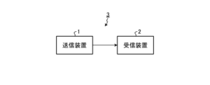
- FIG. 1 is a diagram showing the configuration of a communication system 3 according to the first embodiment.
- the communication system 3 includes a transmitting device 1 and a receiving device 2.
- the communication system 3 performs communication between the transmitting device 1 and the receiving device 2 using wireless signals.
- the communication system 3 uses direct spectrum spreading, which uses a chirp signal whose frequency changes linearly over time to spread the signal over a wider range than the original frequency band.
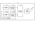
- FIG. 2 is a diagram showing the functional configuration of the transmitting device 1 shown in FIG. 1.
- the transmitter 1 includes a modulator 11 , a spectrum spreader 12 , a preamble generator 13 , a frame generator 14 , a transmit filter 15 , and a transmit antenna 16 .
- the modulation unit 11 generates a data modulation signal by modulating transmission data acquired from a higher-level device (not shown).
- the modulator 11 can use, for example, PSK (Phase Shift Keying) as a modulation method.
- Modulating section 11 outputs the generated modulated signal to spectrum spreading section 12 .
- the spectrum spreading unit 12 directly performs spectrum spreading on the modulated signal output by the modulating unit 11 using the chirp signal as a spreading code.
- An example of a chirp signal used by the spectrum spreader 12 as a spreading code is the Zadoff-Chu sequence.
- C(t) which is the t-th element of the Zadoff-Chu sequence C
- M in formula (1) is a series parameter and has a coprime relationship with Nc. Further, M indicates the number of increases from the minimum frequency fmin to the maximum frequency fmax in the sequence length Nc.
- the spectrum spreading unit 12 outputs the signal subjected to spectrum spreading to the frame generating unit 14. In the following description, the signal generated by the spectrum spreader 12 may be referred to as data.
- the preamble generation unit 13 performs spectrum spreading on a known preamble signal to generate a preamble.
- the preamble generation unit 13 performs spectrum spreading using a method different from the method in which the spectrum spreading unit 12 spreads the spectrum of transmission data.
- Preamble generation section 13 includes a modulation section 131 and a spectrum spreading section 132.
- the signal generated by the preamble generation unit 13 may be referred to as a preamble.
- the modulation unit 131 modulates the known preamble signal in the same manner as the modulation unit 11.
- the known preamble signal signals having the same value such as 0, 0, 0, 0, . . . can be used.
- the modulator 131 uses, for example, QPSK (Quadrature Phase Shift Keying) as a modulation method.
- Modulating section 131 outputs the modulated signal to spectrum spreading section 132 .
- one element of the modulated signal modulated by modulation section 131 may be referred to as a symbol.
- the spectrum spreading unit 132 directly performs spectrum spreading on the modulated signal output by the modulating unit 131 using the chirp signal as a spreading code.
- the chirp signal used by the spectrum spreader 132 is an up-chirp signal or a down-chirp signal.
- An up-chirp signal is a signal whose frequency increases with time, and in this embodiment, the up-chirp signal used by the spectrum spreader 132 is generated with the value of M in the above formula (1) set to 1.
- the signal corresponds to the Zadoff-Chu sequence.
- a down-chirp signal is a signal whose frequency decreases over time, and in this embodiment, the down-chirp signal used by the spectrum spreading section 132 is a signal whose frequency decreases by -1 in the above formula (1).
- the signal corresponds to the Zadoff-Chu sequence generated as follows.
- the spectrum spreading unit 132 spreads each of the two types of preambles with a different chirp signal.
- the preamble that is transmitted first is referred to as a first preamble
- the preamble that is transmitted after the first preamble is referred to as a second preamble.
- the chirp signal used when spreading the first preamble is called a first chirp signal
- the chirp signal used when spreading the second preamble is called a second chirp signal.
- the second chirp signal is a different chirp signal from the first chirp signal.
- the first chirp signal is an up-chirp signal
- the second chirp signal is a down-chirp signal.
- the spectrum spreading unit 132 performs spectrum spreading on the first preamble using an up-chirp signal, which is a first chirp signal, and spread spectrum on the second preamble using a down-chirp signal, which is a second chirp signal. conduct.
- the spectrum spreading unit 132 outputs the signal after spectrum spreading to the frame generating unit 14.
- the frame generation unit 14 frames the spectrum-spread data output from the spectrum spread unit 12 and the spectrum-spread preamble output from the preamble generation unit 13.
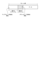
- FIG. 3 is a diagram showing an example of a signal after framing by the frame generation unit 14 shown in FIG. 2.
- the framed signal includes a first preamble, a second preamble transmitted after the first preamble, and data.
- the first preamble is subjected to up-chirp spreading, which is spectrum spreading using an up-chirp signal
- the second preamble is subjected to down-chirp spreading, which is spectrum spreading using a down-chirp signal.
- the length of the second preamble can be equal to the length of the first preamble, or can be shorter than the length of the first preamble depending on the propagation environment and requirements.
- the frame generation unit 14 sequentially outputs the framed signals to the transmission filter 15.
- the transmission filter 15 performs band limitation on the framed signal output by the frame generation unit 14.
- the transmission filter 15 outputs each of the plurality of band-limited signals to the transmission antenna 16.
- the transmitting antenna 16 transmits each of the plurality of band-limited signals output by the transmitting filter 15.
- the transmitting antenna 16 wirelessly transmits a signal toward the receiving device 2 .
- FIG. 4 is a diagram showing the functional configuration of the receiving device 2 shown in FIG. 1.
- the receiving device 2 includes a receiving antenna 21, a receiving filter 22, an initial synchronization section 23, a frame synchronization section 24, a fine synchronization section 25, a frequency offset correction section 26, a despreading section 27, and a demodulation section 28. has.
- the receiving antenna 21 receives wireless signals.
- a received signal which is a signal received by the receiving antenna 21, is a signal transmitted from the transmitting device 1.
- the receiving antenna 21 outputs the received signal to the receiving filter 22.
- the reception filter 22 performs filter processing on the reception signal output by the reception antenna 21.
- the reception filter 22 outputs the filtered signal to the initial synchronization section 23, the frame synchronization section 24, and the frequency offset correction section 26, respectively.
- the initial synchronization unit 23 performs initial synchronization based on the filtered signal output by the reception filter 22.
- the initial synchronization unit 23 roughly estimates the spreading code timing, which is the timing at which the spreading code is multiplied in the transmitting device 1, and the frequency shift of the local oscillator between the transmitting device 1 and the receiving device 2.
- a rough estimate of the amount of frequency offset generated is performed.
- the coarse estimation of the amount of frequency offset refers to estimation of the amount of frequency offset performed with coarse accuracy compared to the estimation accuracy of the amount of frequency offset by the fine synchronization unit 25 described later.
- the initial synchronization unit 23 outputs the rough estimation result of the spreading code timing and the rough estimation result of the frequency offset amount to the frame synchronization unit 24. The detailed configuration and operation of the initial synchronization unit 23 will be described later.
- the frame synchronization unit 24 performs frame synchronization to synchronize frame timing based on the rough estimation result of the spreading code timing output by the initial synchronization unit 23.
- the frame synchronization unit 24 outputs the coarse estimation result of the spreading code timing, the rough estimation result of the frequency offset amount, and the estimation result of the frame timing to the fine synchronization unit 25.
- the fine synchronization unit 25 corrects the residual spread code timing error and frequency offset amount based on the frame timing output from the frame synchronization unit 24, thereby adjusting the spread code timing and frequency offset from the initial synchronization unit 23. It also estimates with high accuracy.
- the precise synchronization unit 25 uses, for example, a circuit called AFC (Automatic Frequency Control) to perform synchronization processing with higher accuracy than the initial synchronization unit 23.
- the precision synchronization unit 25 outputs the estimation result of the frequency offset amount to the frequency offset correction unit 26 and outputs the estimation result of the spreading code timing to the despreading unit 27.
- the frequency offset correction unit 26 corrects the frequency offset of the signal output by the reception filter 22 based on the estimation result of the frequency offset amount output by the fine synchronization unit 25.
- the frequency offset correction section 26 outputs the signal after correcting the frequency offset to the despreading section 27 .
- the despreading unit 27 performs despreading on the frequency offset corrected signal output by the frequency offset correction unit 26 based on the estimation result of the spreading code timing output by the fine synchronization unit 25.
- the despreader 27 outputs the despread signal to the demodulator 28 .
- the demodulator 28 performs demodulation processing on the despread signal output from the despreader 27.
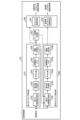
- FIG. 5 is a diagram showing a detailed functional configuration of the initial synchronization section 23 shown in FIG. 4.
- the initial synchronization section 23 includes a first timing detection section 231, a search range calculation section 237, a second timing detection section 238, and a coarse estimation section 240.
- the first timing detection section 231 detects the first timing n1 based on the first correlation value, which is the value of the cross-correlation function between the received signal and the first chirp signal.
- the first timing n1 is the timing at which the first correlation value reaches its peak and exceeds the threshold value.
- the first timing detection section 231 includes a first correlation value calculation section 232, a power value calculation section 233, an averaging section 234, a correlation power memory 235, and a threshold determination section 236.
- the first correlation value calculation section 232 uses a matched filter to combine the filtered reception signal output by the reception filter 22 with the first chirp signal used when spectrum spreading is performed by the preamble generation section 13 of the transmission device 1.
- a first correlation value is calculated, which is the value of the cross-correlation function of .
- the first correlation value calculation unit 232 outputs the calculated first correlation value to the power value calculation unit 233.
- the power value calculation unit 233 calculates the power value by squaring the first correlation value output by the first correlation value calculation unit 232.
- the power value calculation unit 233 outputs the calculated power value to the averaging unit 234.
- the averaging unit 234 averages the power value output by the power value calculation unit 233 with the power value of the previous symbol at the same sample timing.
- the averaging unit 234 stores the averaged power value in the correlation power memory 235.
- the correlation power memory 235 is configured to hold a number of power values corresponding to the spreading code length Nc x the number of oversamples Novs, and uses the averaged power values output by the averaging section 234 as the spreading code length Nc. It is stored over one symbol period which is x the number of oversamples Novs.
- the processing up to the averaging unit 234 operates on a sample time basis, but the processing after the correlation power memory 235 changes to operation on a symbol time basis.
- the threshold determination unit 236 detects the first timing n1 from the power value for one period of the spreading code held in the correlation power memory 235. Specifically, the threshold determination unit 236 detects the maximum power value among the power values for one period of the spreading code held in the correlation power memory 235, and compares the detected maximum power value with the threshold. If the maximum power value exceeds the threshold, the threshold determination unit 236 detects the sample timing corresponding to the maximum power value as the first timing n1, and sets the first timing n1 to the search range calculation unit 237 and the rough It is output to each of the estimators 240. Since the power value is the square of the first correlation value, the first correlation value reaches its peak at the sample timing when the power value reaches its peak. Further, the threshold determining section 236 outputs symbol numbers exceeding the threshold to the second timing detecting section 238.
- the search range calculation unit 237 calculates a search range, which is the range of timings in which calculations are performed in the second timing detection unit 238 and thereafter, based on the first timing n1 output by the first timing detection unit 231.
- the search range is a range in which the second timing detection section 238 calculates a second correlation value, which is a value of a cross-correlation function between the second chirp signal and the received signal.
- the search range calculation unit 237 can calculate the search range based on the maximum amount of frequency offset expected in the environment in which the search range is used.
- the search range calculation unit 237 calculates the search range when
- the second timing detection unit 238 calculates a second correlation value limited to the search range determined by the search range calculation unit 237, and detects the second timing n2 based on the second correlation value.
- the second timing n2 is the timing at which the second correlation value reaches its peak and exceeds the threshold value.
- the second timing detection section 238 includes a second correlation value calculation section 239, a power value calculation section 233a, an averaging section 234a, a correlation power memory 235a, and a threshold determination section 236a.
- the second correlation value calculation unit 239 uses a matched filter to calculate the received signal output from the reception filter 22 after filter processing and the second chirp signal used when spectrum spreading is performed by the preamble generation unit 13 of the transmission device 1.
- a second correlation value is calculated, which is the value of the cross-correlation function with.
- the second correlation value calculation unit 239 outputs the second correlation value to the power value calculation unit 233a.
- the power value calculation unit 233a calculates the power value by squaring the second correlation value output by the second correlation value calculation unit 239.
- the power value calculation unit 233a outputs the calculated power value to the averaging unit 234a.
- the averaging unit 234a averages the power value output by the power value calculation unit 233a with the power value at the same sample timing of the previous symbol.
- the averaging unit 234a stores the averaged power value in the correlation power memory 235a.
- the correlation power memory 235a is configured to be able to hold a number of power values corresponding to the spreading code length Nc x the number of oversamples Novs, and the averaged power value output by the averaging section 234a is divided into Nc x oversamples. It is stored over one symbol period, which is several Novs.
- the processing up to the averaging unit 234a operates on a sample time basis, but the processing after the correlation power memory 235a changes to operation on a symbol time basis.
- the threshold determination unit 236a detects the second timing n2 from the power value for one period of the spreading code stored in the correlation power memory 235a. Specifically, the threshold determination unit 236a detects the maximum power value among the power values for one cycle of the spreading code held in the correlation power memory 235a, and compares the detected maximum power value with a predetermined threshold. Compare. If the maximum power value exceeds the threshold, the threshold determination unit 236a detects the sample timing corresponding to the maximum power value as the second timing n2, and outputs the second timing n2 to the coarse estimation unit 240.
- the threshold values used by each of the threshold determination units 236 and 236a may be predetermined values, or may be dynamically generated as described below.
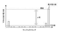
- the threshold determination unit 236 can calculate the average of the power values for one spreading code period read from the correlation power memory 235, and set the average value multiplied by a constant ⁇ as the threshold.
- FIG. 6 is an explanatory diagram of threshold setting in the threshold value determination units 236, 236a shown in FIG. 5. The horizontal axis in FIG.
- the threshold determination units 236 and 236a calculate the average of the averaged power values of each sample timing for one spreading code period, and set ⁇ times the average as the threshold.
- Each of the threshold determination units 236 and 236a can detect the first timing n1 or the second timing n2 based on the comparison result between the threshold value set in this manner and the maximum power value.
- the coarse estimation section 240 includes a timing coarse estimation section 241 and a frequency offset coarse estimation section 242.
- the rough timing estimator 241 determines the spread code in the transmitter 1 that has transmitted the received signal based on the first timing n1 output by the threshold determiner 236 and the second timing n2 output by the threshold determiner 236a.
- a rough estimation result of the spread code timing which is the multiplied timing, can be obtained.
- the rough timing estimator 241 can set the spreading code timing to a third timing n0 that is intermediate between the first timing n1 and the second timing n2.
- the rough timing estimator 241 may round off the intermediate third timing n0 to a decimal number.
- the third timing n0 is expressed by the following equation (2).
- the rough timing estimation unit 241 outputs the estimated spreading code timing to the frame synchronization unit 24 as a result of rough estimation of the spreading code timing.
- the frequency offset coarse estimator 242 calculates the difference between the transmitting device 1 and the receiving device 2 based on the first timing n1 outputted by the threshold determining unit 236 and the second timing n2 outputted by the threshold determining unit 236a. A rough estimate of the amount of frequency offset can be obtained.
- the frequency offset coarse estimator 242 can calculate the frequency offset amount using the following formula (3).
- the frequency offset rough estimation unit 242 outputs the estimated frequency offset amount to the frame synchronization unit 24 as a rough estimation result of the frequency offset amount.
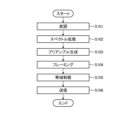
- FIG. 7 is a flowchart for explaining the operation of the transmitting device 1 shown in FIG. 2.
- the modulating unit 11 of the transmitting device 1 modulates transmission data acquired from a higher-level device (not shown) (step S101).
- the modulator 11 outputs a modulated signal, which is a modulated signal, to the spectrum spreader 12 .
- the spectrum spreading unit 12 performs spectrum spreading on the modulated signal output by the modulating unit 11 (step S102).
- the spectrum spreader 12 outputs the signal after spectrum spreading to the frame generator 14 .
- the preamble generation unit 13 performs spectrum spreading on the known preamble signal using a method different from that of the spectrum spreading unit 12, and generates a preamble (step S103).
- the preamble generation unit 13 outputs the generated preamble to the frame generation unit 14.
- the frame generator 14 frames the data output by the spectrum spreader 12 and the preamble output by the preamble generator 13 (step S104).
- the frame generation unit 14 outputs the framed signal to the transmission filter 15.
- the transmission filter 15 performs band limitation on the signal after framing (step S105).
- the transmission filter 15 outputs the band-limited signal to the transmission antenna 16.
- the transmitting antenna 16 transmits the signal output by the transmitting filter 15 (step S106).
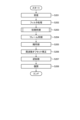
- FIG. 8 is a flowchart for explaining the operation of the receiving device 2 shown in FIG. 4.
- the receiving antenna 21 of the receiving device 2 receives the signal transmitted from the transmitting device 1 (step S201).
- the receiving antenna 21 outputs the received signal to the receiving filter 22.
- the reception filter 22 performs filter processing on the reception signal output by the reception antenna 21 (step S202).
- the reception filter 22 outputs the filtered signal to the initial synchronization section 23, the frame synchronization section 24, and the frequency offset correction section 26.
- the initial synchronization unit 23 performs initial synchronization based on the signal output by the reception filter 22 (step S203). Details of step S203 will be described later.
- the initial synchronization unit 23 outputs to the frame synchronization unit 24 a rough estimation result of the spreading code timing generated by the initial synchronization and a rough estimation result of the frequency offset amount.
- the frame synchronization unit 24 performs frame synchronization to synchronize frame timing with respect to the signal output from the reception filter 22, based on the rough estimation result of the spreading code timing output from the initial synchronization unit 23 (step S204).
- the frame synchronization unit 24 outputs the frame timing estimation result, the spreading code timing rough estimation result, and the frequency offset amount estimation result to the fine synchronization unit 25.
- the fine synchronization unit 25 corrects the error included in the rough estimation result of the spreading code timing and the rough estimation result of the frequency offset amount based on the frame timing output from the frame synchronization unit 24, and corrects the error included in the rough estimation result of the spreading code timing and the frequency offset amount. Precise synchronization is performed to estimate more accurately than the initial synchronization unit 23 (step S205).
- the precise synchronization unit 25 outputs the estimation result of the spreading code timing to the despreading unit 27 and outputs the estimation result of the frequency offset amount to the frequency offset correction unit 26.
- the frequency offset correction unit 26 corrects the frequency offset of the signal output by the reception filter 22 based on the estimation result of the frequency offset amount output by the fine synchronization unit 25 (step S206).
- the frequency offset correction section 26 outputs the corrected signal to the despreading section 27.
- the despreading unit 27 performs despreading on the frequency offset corrected signal output from the frequency offset correction unit 26 based on the estimation result of the spreading code timing output from the precision synchronization unit 25 (step S207). .
- the despreader 27 outputs the despread signal to the demodulator 28 .
- the demodulator 28 demodulates the despread signal output from the despreader 27 (step S208).
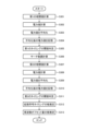
- FIG. 9 is a flowchart for explaining the detailed operation of the initial synchronization shown in FIG. 8.
- the first correlation value calculation unit 232 of the initial synchronization unit 23 calculates a first correlation value (step S301).
- the first correlation value calculation unit 232 outputs the calculated first correlation value to the power value calculation unit 233.
- the power value calculation unit 233 calculates the power value by squaring the first correlation value (step S302).
- the power value calculation unit 233 outputs the calculated power value to the averaging unit 234.
- the averaging unit 234 averages the power value output by the power value calculation unit 233 with the power value at the same sample timing of the previous symbol (step S303).
- the averaging unit 234 stores the averaged power value in the correlation power memory 235.
- the correlation power memory 235 stores the averaged power value from the averaging unit 234 (step S304).
- the threshold determination unit 236 performs threshold determination at the first timing n1 at which the first correlation value reaches a peak, based on the power value stored in the correlation power memory 235 (step S305). Specifically, the threshold determination unit 236 extracts the maximum power value from among the plurality of power values for one period of the spreading code stored in the correlation power memory 235, and sets the extracted maximum power value and the threshold value. compare. If the maximum power value exceeds the threshold, the threshold determination unit 236 outputs the sample timing corresponding to the maximum power value to the rough estimation unit 240 and the search range calculation unit 237 as the first timing n1.
- the search range calculation unit 237 calculates the search range based on the first timing n1 output by the threshold determination unit 236 (step S306).
- the search range calculation unit 237 outputs the calculated search range to the second timing detection unit 238.
- the second correlation value calculation unit 239 of the second timing detection unit 238 calculates a second correlation value by limiting the time range to the search range output by the search range calculation unit 237 (step S307). Specifically, the second correlation value calculation unit 239 calculates the second correlation value from the symbol corresponding to the maximum power value determined by the threshold value determination unit 236 to exceed the threshold value. The second correlation value calculation unit 239 outputs the calculated second correlation value to the power value calculation unit 233a.
- the power value calculation unit 233a calculates the power value by squaring the second correlation value output by the second correlation value calculation unit 239 (step S308).
- the power value calculation unit 233a outputs the calculated power value to the averaging unit 234a.
- the averaging unit 234a averages the power value output by the power value calculation unit 233a with the power value at the same sample timing of the previous symbol (step S309).
- the averaging unit 234a stores the averaged power value in the correlation power memory 235a.
- the correlation power memory 235a stores the averaged power value from the averaging unit 234a (step S310).
- the threshold determination unit 236a performs threshold determination at the second timing n2 when the second correlation value reaches its peak, based on the power value stored in the correlation power memory 235a (step S311). Specifically, the threshold determination unit 236a extracts the maximum power value from among the power values for one period of the spreading code stored in the correlation power memory 235a, and compares the extracted maximum power value with a threshold value. . If the maximum power value exceeds the threshold, the threshold determination unit 236a outputs the sample timing corresponding to the maximum power value to the rough estimation unit 240 as the second timing n2.
- the rough timing estimation unit 241 of the rough estimation unit 240 performs rough estimation of the spreading code timing based on the first timing n1 and the second timing n2 (step S312).
- the rough timing estimation section 241 outputs the result of rough estimation of the spreading code timing to the frame synchronization section 24 .
- the frequency offset coarse estimator 242 of the coarse estimator 240 roughly estimates the frequency offset amount based on the first timing n1 and the second timing n2 (step S313).
- the frequency offset rough estimator 242 outputs the rough estimation result of the frequency offset amount to the frame synchronizer 24.
- the receiving antenna 21 is realized by an antenna device.
- the reception filter 22 is realized by a filter circuit.
- the initial synchronization section 23, frame synchronization section 24, fine synchronization section 25, frequency offset correction section 26, despreading section 27, and demodulation section 28 are realized by processing circuits.
- the processing circuit may be a processor and memory that executes a program stored in memory, or may be dedicated hardware.
- the processing circuit is also called a control circuit.
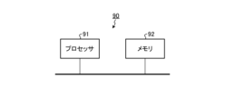
- FIG. 10 is a diagram showing an example of the configuration of the processing circuit 90 when the processing circuit included in the receiving device 2 shown in FIG. 4 is implemented by the processor 91 and the memory 92.
- a processing circuit 90 shown in FIG. 10 is a control circuit and includes a processor 91 and a memory 92.
- each function of the processing circuit 90 is realized by software, firmware, or a combination of software and firmware.
- Software or firmware is written as a program and stored in memory 92.
- each function is realized by a processor 91 reading and executing a program stored in a memory 92.
- the processing circuit 90 includes a memory 92 for storing a program by which the processing of the receiving device 2 is executed as a result.
- This program can also be said to be a program for causing the receiving device 2 to execute each function realized by the processing circuit 90.
- This program may be provided by a storage medium in which the program is stored, or may be provided by other means such as a communication medium.
- the processor 91 is, for example, a CPU (Central Processing Unit), a processing device, an arithmetic device, a microprocessor, a microcomputer, or a DSP (Digital Signal Processor).
- the memory 92 may be a nonvolatile or volatile memory such as RAM (Random Access Memory), ROM (Read Only Memory), flash memory, EPROM (Erasable Programmable ROM), or EEPROM (registered trademark) (Electrically EPROM). This includes semiconductor memory, magnetic disks, flexible disks, optical disks, compact disks, mini disks, and DVDs (Digital Versatile Discs).
- FIG. 11 is a diagram showing an example of the processing circuit 93 in the case where the processing circuit included in the receiving device 2 shown in FIG. 4 is configured with dedicated hardware.
- the processing circuit 93 shown in FIG. 11 is, for example, a single circuit, a composite circuit, a programmed processor, a parallel programmed processor, an ASIC (Application Specific Integrated Circuit), an FPGA (Field Programmable Gate Array), or a combination of these. applicable.
- a part may be realized by dedicated hardware, and a part may be realized by software or firmware. In this way, the processing circuit can implement each of the above-mentioned functions using dedicated hardware, software, firmware, or a combination thereof.
- the transmitting antenna 16 is realized by an antenna device.
- the transmission filter 15 is realized by a filter circuit.
- the modulator 11, spectrum spreader 12, preamble generator 13, and frame generator 14 are realized by processing circuits.
- the processing circuit may be a processor and memory that executes a program stored in memory, or may be dedicated hardware.
- each of the plurality of functional blocks shown in FIG. 2 and FIGS. 4 and 5 does not necessarily need to be realized by one processing circuit.
- the functions of a plurality of functional blocks may be realized by one processing circuit, or the functions of one functional block may be realized by a plurality of processing circuits.
- the preamble generation unit 13 of the transmitting device 1 spreads the spectrum of the first preamble transmitted initially using the first chirp signal, and A second preamble transmitted after the first preamble is subjected to spectrum spreading using a second chirp signal that is a different chirp signal from the first chirp signal.
- the first timing detection section 231 of the initial synchronization section 23 first calculates a first correlation value, which is the value of the cross-correlation function between the first chirp signal and the received signal, and calculates the first correlation value.
- a first timing n1 at which the correlation value reaches a peak is detected.
- the search range calculation unit 237 of the initial synchronization unit 23 calculates a range for calculating a second correlation value, which is a value of a cross-correlation function between the second chirp signal and the received signal, based on the detected first timing n1. Calculate the search range that is .
- the second timing detection unit 238 calculates the second correlation value within the search range, and detects the second timing n2 at which the second correlation value reaches its peak.
- the coarse estimation section 240 of the initial synchronization section 23 obtains a coarse estimation result of the spreading code timing based on the first timing n1 and the second timing n2.
- the calculation range in the second timing detection section 238 is limited to the search range, so by using two types of chirp signals, frequency offset resistance is improved and the amount of calculations in the initial synchronization section 23 is reduced. be able to. Therefore, it is possible to reduce the scale of the circuit for realizing the initial synchronization section 23.
- the initial synchronization unit 23 further includes a frequency offset coarse estimating unit 242 that obtains a rough estimation result of the frequency offset amount with respect to the transmitting device 1 based on the first timing n1 and the second timing n2. This makes it possible to obtain a rough estimation result of the frequency offset amount while reducing the amount of calculation by the initial synchronization unit 23.
- the configuration shown in the above embodiments is an example, and it is possible to combine it with another known technology, and a part of the configuration can be omitted or changed without departing from the gist. It is possible.
- the down chirp signal is used, the present embodiment is not limited to such an example. It is sufficient that the first chirp signal and the second chirp signal are different chirp signals.
- the different chirp signals may be chirp signals that differ in at least one of the slope of frequency change over time, the minimum frequency fmin, and the maximum frequency fmax.
- the first preamble may be an up-chirp signal and the second preamble may be a down-chirp signal, or the first preamble may be a down-chirp signal and the second preamble may be an up-chirp signal.
- both the first preamble and the second preamble may be up-chirp signals, or both the first preamble and the second preamble may be down-chirp signals.
- the search range calculation unit 237 of the initial synchronization unit 23 calculates the search range based on the absolute value of the maximum offset amount assumed in the environment in which it is used and the first timing n1.
- the method for determining the search range is not limited to this example.
- the search range calculation unit 237 may determine the search range by considering the amount of delay of delayed waves. This makes it possible to improve the accuracy of initial synchronization in a multipath environment.
Landscapes
- Engineering & Computer Science (AREA)
- Computer Networks & Wireless Communication (AREA)
- Signal Processing (AREA)
- Mobile Radio Communication Systems (AREA)
- Synchronisation In Digital Transmission Systems (AREA)
Priority Applications (2)
| Application Number | Priority Date | Filing Date | Title |
|---|---|---|---|
| JP2023572656A JP7446550B2 (ja) | 2022-03-07 | 2022-03-07 | 受信装置、通信システム、制御回路、記憶媒体および通信方法 |
| PCT/JP2022/009768 WO2023170754A1 (ja) | 2022-03-07 | 2022-03-07 | 受信装置、通信システム、制御回路、記憶媒体および通信方法 |
Applications Claiming Priority (1)
| Application Number | Priority Date | Filing Date | Title |
|---|---|---|---|
| PCT/JP2022/009768 WO2023170754A1 (ja) | 2022-03-07 | 2022-03-07 | 受信装置、通信システム、制御回路、記憶媒体および通信方法 |
Publications (1)
| Publication Number | Publication Date |
|---|---|
| WO2023170754A1 true WO2023170754A1 (ja) | 2023-09-14 |
Family
ID=87936254
Family Applications (1)
| Application Number | Title | Priority Date | Filing Date |
|---|---|---|---|
| PCT/JP2022/009768 Ceased WO2023170754A1 (ja) | 2022-03-07 | 2022-03-07 | 受信装置、通信システム、制御回路、記憶媒体および通信方法 |
Country Status (2)
| Country | Link |
|---|---|
| JP (1) | JP7446550B2 (cg-RX-API-DMAC7.html) |
| WO (1) | WO2023170754A1 (cg-RX-API-DMAC7.html) |
Cited By (1)
| Publication number | Priority date | Publication date | Assignee | Title |
|---|---|---|---|---|
| US12671613B2 (en) | 2024-11-27 | 2026-06-30 | Stmicroelectronics International N.V. | Preamble detection for wireless power ask communication |
Citations (4)
| Publication number | Priority date | Publication date | Assignee | Title |
|---|---|---|---|---|
| JP2011130142A (ja) * | 2009-12-17 | 2011-06-30 | Fujitsu Ltd | フレームタイミング検出装置及び検出方法 |
| US20130051433A1 (en) * | 2011-08-30 | 2013-02-28 | Cambridge Silicon Radio Limited | Chirp Receiver |
| JP2018524890A (ja) * | 2015-06-19 | 2018-08-30 | クゥアルコム・インコーポレイテッドQualcomm Incorporated | システム走査および取得 |
| WO2021140627A1 (ja) * | 2020-01-09 | 2021-07-15 | 三菱電機株式会社 | 受信装置、送信装置、通信システム、制御回路、記憶媒体、受信同期方法および送信方法 |
-
2022
- 2022-03-07 WO PCT/JP2022/009768 patent/WO2023170754A1/ja not_active Ceased
- 2022-03-07 JP JP2023572656A patent/JP7446550B2/ja active Active
Patent Citations (4)
| Publication number | Priority date | Publication date | Assignee | Title |
|---|---|---|---|---|
| JP2011130142A (ja) * | 2009-12-17 | 2011-06-30 | Fujitsu Ltd | フレームタイミング検出装置及び検出方法 |
| US20130051433A1 (en) * | 2011-08-30 | 2013-02-28 | Cambridge Silicon Radio Limited | Chirp Receiver |
| JP2018524890A (ja) * | 2015-06-19 | 2018-08-30 | クゥアルコム・インコーポレイテッドQualcomm Incorporated | システム走査および取得 |
| WO2021140627A1 (ja) * | 2020-01-09 | 2021-07-15 | 三菱電機株式会社 | 受信装置、送信装置、通信システム、制御回路、記憶媒体、受信同期方法および送信方法 |
Non-Patent Citations (3)
| Title |
|---|
| MEGUMI FUKUMA, MASATSUGU HIGASHINAKA , RYOSUKE NAKAMURA, AND HIROSHI ARUGA: "A Novel Code Acquisition Scheme Using Multiple Chirp Signals Robust to Initial Frequency Offset", IEICE TECHNICAL REPORT, vol. 119, no. 377 (IT2019-46), 16 January 2020 (2020-01-16), pages 63 - 68, XP009548839, ISSN: 0913-5685 * |
| MEGUMI FUKUMA, MASATSUGU HIGASHINAKA, AKINORI OHASHI, HIROSHI ARIGA: "B-5-58 Evaluation of characteristics of DS-SS initial acquisition in multipath environment using two chirp signals", IEICE 2020 COMMUNICATION SOCIETY CONFERENCE PROCEEDINGS 1; 2020.09.15-18, IEICE, JP, 1 September 2020 (2020-09-01) - 18 September 2020 (2020-09-18), JP, pages 258, XP009549411 * |
| MEGUMI FUKUMA, MASATSUGU HIGASHINAKA, RYOSUKE NAKAMURA, HIROSHI ARUGA: "A Frame Timing Detection Scheme Using Multiple Zadoff-Chu Sequences for DS-SS Systems Employing Space-time Block Codes", IEICE TECHNICAL REPORT, vol. 121, no. 7, 15 April 2021 (2021-04-15), pages 36 - 41, XP009539539, ISSN: 2432-6380 * |
Cited By (1)
| Publication number | Priority date | Publication date | Assignee | Title |
|---|---|---|---|---|
| US12671613B2 (en) | 2024-11-27 | 2026-06-30 | Stmicroelectronics International N.V. | Preamble detection for wireless power ask communication |
Also Published As
| Publication number | Publication date |
|---|---|
| JPWO2023170754A1 (cg-RX-API-DMAC7.html) | 2023-09-14 |
| JP7446550B2 (ja) | 2024-03-08 |
Similar Documents
| Publication | Publication Date | Title |
|---|---|---|
| EP0820156B1 (en) | Reception timing detection circuit of CDMA receiver and detection method | |
| JP6999869B2 (ja) | 受信装置、通信システム、制御回路、記憶媒体および受信同期方法 | |
| US6829291B1 (en) | Receiving apparatus and synchronization capturing method | |
| GB2367211A (en) | Slot timing acquisition and local oscillator frequency offset correction in a direct sequence spread spectrum receiver | |
| US9516616B2 (en) | Method and apparatus for estimating frequency errors | |
| US7085311B2 (en) | Apparatus and method for measuring SIR in CDMA communication system | |
| JP7004876B2 (ja) | 受信装置、制御回路、記憶媒体および通信システム | |
| JP7446550B2 (ja) | 受信装置、通信システム、制御回路、記憶媒体および通信方法 | |
| KR20040107889A (ko) | 시분할 동기 코드 분할 방식의 채널 판단 방법 | |
| EP2560292A1 (en) | CDMA communications device and related methods | |
| EP1454421A1 (en) | Interference suppression in a cdma radio receiver | |
| KR20040017859A (ko) | 게이트된 파일럿의 획득 | |
| JP5634354B2 (ja) | 通信システムおよび受信機 | |
| US20240275639A1 (en) | Communication apparatus, communication system, communication method, control circuit, and storage medium | |
| KR20040022971A (ko) | 이동단말에서 파일롯 신호의 의사잡음 시퀀스 위상을추적하기 위한 장치 및 방법 | |
| US12506651B2 (en) | Method and device for synchronization | |
| US9014234B2 (en) | Communication system and communication method | |
| CN121153234A (zh) | 超宽带系统中的多毫秒测距 | |
| JP7378687B2 (ja) | 受信装置、受信同期方法、制御回路、および記憶媒体 | |
| JP7270858B2 (ja) | 送信装置、受信装置、通信システム、送信方法、タイミング同期方法、制御回路および記憶媒体 | |
| JP7366329B2 (ja) | 受信装置、通信システム、制御回路および記憶媒体 | |
| US8184742B2 (en) | RF receiver having timing offset recovery function and timing offset recovery method using thereof | |
| JP2006519567A (ja) | 受信インパルス無線信号を捕捉する方法およびシステム | |
| US7881418B2 (en) | Device, method and program for detecting communication frame base point through blind processing | |
| US12483285B2 (en) | Communication apparatus |
Legal Events
| Date | Code | Title | Description |
|---|---|---|---|
| 121 | Ep: the epo has been informed by wipo that ep was designated in this application |
Ref document number: 22930740 Country of ref document: EP Kind code of ref document: A1 |
|
| WWE | Wipo information: entry into national phase |
Ref document number: 2023572656 Country of ref document: JP |
|
| NENP | Non-entry into the national phase |
Ref country code: DE |
|
| 122 | Ep: pct application non-entry in european phase |
Ref document number: 22930740 Country of ref document: EP Kind code of ref document: A1 |