WO2023167136A1 - 金属部材の接合方法、部材の接合方法および金属部材接合構造 - Google Patents
金属部材の接合方法、部材の接合方法および金属部材接合構造 Download PDFInfo
- Publication number
- WO2023167136A1 WO2023167136A1 PCT/JP2023/007049 JP2023007049W WO2023167136A1 WO 2023167136 A1 WO2023167136 A1 WO 2023167136A1 JP 2023007049 W JP2023007049 W JP 2023007049W WO 2023167136 A1 WO2023167136 A1 WO 2023167136A1
- Authority
- WO
- WIPO (PCT)
- Prior art keywords
- metal member
- joining
- metal
- hole
- shaft portion
- Prior art date
- Legal status (The legal status is an assumption and is not a legal conclusion. Google has not performed a legal analysis and makes no representation as to the accuracy of the status listed.)
- Ceased
Links
Images














Classifications
-
- B—PERFORMING OPERATIONS; TRANSPORTING
- B23—MACHINE TOOLS; METAL-WORKING NOT OTHERWISE PROVIDED FOR
- B23K—SOLDERING OR UNSOLDERING; WELDING; CLADDING OR PLATING BY SOLDERING OR WELDING; CUTTING BY APPLYING HEAT LOCALLY, e.g. FLAME CUTTING; WORKING BY LASER BEAM
- B23K26/00—Working by laser beam, e.g. welding, cutting or boring
- B23K26/20—Bonding
- B23K26/21—Bonding by welding
-
- Y—GENERAL TAGGING OF NEW TECHNOLOGICAL DEVELOPMENTS; GENERAL TAGGING OF CROSS-SECTIONAL TECHNOLOGIES SPANNING OVER SEVERAL SECTIONS OF THE IPC; TECHNICAL SUBJECTS COVERED BY FORMER USPC CROSS-REFERENCE ART COLLECTIONS [XRACs] AND DIGESTS
- Y02—TECHNOLOGIES OR APPLICATIONS FOR MITIGATION OR ADAPTATION AGAINST CLIMATE CHANGE
- Y02T—CLIMATE CHANGE MITIGATION TECHNOLOGIES RELATED TO TRANSPORTATION
- Y02T10/00—Road transport of goods or passengers
- Y02T10/60—Other road transportation technologies with climate change mitigation effect
- Y02T10/64—Electric machine technologies in electromobility
Definitions
- the present invention relates to a metal member joining method, a member joining method, and a metal member joining structure.
- JP-A-2018-83329 discloses a metal member joining method for joining a metal first joining member and a metal second joining member.
- a method of joining metal members includes the step of forming a weld boss on a first joining member.
- a method for joining metal members includes the step of forming an insertion hole into which a welding boss can be inserted in a second joining member.
- a method for joining metal members includes a step of pressing a heated thermal caulking tool against the tip of the welding boss protruding from the insertion hole after the welding boss is inserted into the insertion hole.
- the method of joining metal members disclosed in Japanese Patent Application Laid-Open No. 2018-83329 when performing the step of pressing a heated thermal caulking tool against the tip of the welding boss projecting from the insertion hole, the first joining member and the second joining member If the members are made of a material with low rigidity, the first and second joining members are clamped (fixed by sandwiching) in order to prevent the welding bosses from moving due to the pressing force of the thermal crimping tool. There is a need. In this case, the method of joining metal members disclosed in Japanese Patent Application Laid-Open No. 2018-83329 requires a dedicated clamping device for clamping the first joining member and the second joining member.
- the size and complexity of the device for joining the metal members is increased by the clamping device. It is desired to suppress the enlargement and complication of . Further, when both the first joint member and the second joint member are entirely melted and the first joint member and the second joint member are joined only by welding, the first joint member and the second joint member are welded together. Since the area of the compound (intermetallic compound) generated due to welding increases, the bonding strength between the first joining member and the second joining member decreases due to the compound. There is also a point.
- the present invention has been made to solve the above-described problems, and one object of the present invention is to provide a metal jointing device capable of suppressing an increase in size and complication of a device for joining metal members.
- An object of the present invention is to provide a member joining method, a member joining method, and a metal member joining structure.
- a method for joining metal members includes a first metal member preparing step of preparing a first metal member made of metal having through holes; a second metal member preparing step of preparing a second metal member separate from the first metal member having a shaft portion that can be inserted into the through hole; inserting the shaft portion of the second metal member into the through hole of the first metal member; and inserting either the first metal member or the second metal member without pressing the second metal member while the shaft portion of the second metal member is inserted into the through hole of the first metal member. and a joining step of melting and joining the first metal member and the second metal member.
- the second metal member is pressed while the shaft portion of the second metal member is inserted into the through hole of the first metal member. Instead, a joining step of melting one of the first metal member and the second metal member to join the first metal member and the second metal member is provided. As a result, external force is less likely to be applied to the second metal member, so even if the first metal member and the second metal member are made of a material with low rigidity, the first metal member can be held in a position-fixed state by sandwiching the second metal member. and the second metal member need not be melted.
- the increase in size and complexity of the device for joining the metal members can be suppressed because a dedicated clamping device for sandwiching and fixing the position of the second metal member is not provided.
- the area of the compound (intermetallic compound) generated due to the welding of the first metal member and the second metal member can be suppressed. As a result, it is possible to suppress a decrease in the bonding strength between the first metal member and the second metal member caused by the compound.
- the joining step comprises: joining the first metal member and the second metal member by a high-density energy beam or a high-temperature heat source without pressing the second metal member; It includes the step of fusing and joining any of the members.
- either the first metal member or the second metal member can be melted by the high-density energy beam from a position distant from the second metal member. It is possible to prevent a load from being applied to the second metal member when melting any one of the above. Further, a high-temperature heat source having a high heat source temperature can melt either the first metal member or the second metal member simply by slightly contacting either the first metal member or the second metal member. , the load applied to the second metal member can be reduced when either the first metal member or the second metal member is melted.
- the step of preparing the second metal member includes forming a rod-shaped second metal member having a shaft portion with a tip portion thinner than the other portion. Including the step of preparing.
- the shaft can be formed by cutting, pressing, or the like, so that the processing method for forming the shaft can be simplified.
- the method for joining metal members according to the first aspect preferably further comprises the step of forming, in at least one of the through hole and the shaft portion, a non-circular anti-rotation portion that stops rotation of the shaft portion with respect to the through hole.
- the rotation of the shaft in the through hole can be restricted by the anti-rotation portion, so that the first metal member and the second metal member can be positioned in the rotation direction of the shaft.
- the joining step preferably includes irradiating a high-density energy beam to melt both the first metal member and the second metal member to form the first metal member.
- the method includes partially joining the second metal member by welding and melting either the first metal member or the second metal member to join the first metal member and the second metal member.
- the portion where the first metal member and the second metal member are partially welded can restrict the rotation of the shaft portion in the through hole.
- the members can be joined so as to prevent movement in the direction of rotation of the shaft.
- the high-density energy beam is applied to either the first metal member or the second metal member without pressing the second metal member. Laser melting and joining.
- either the first metal member or the second metal member can be melted by a simple method, so the complication of the device for joining the metal members can be suppressed.
- the second metal member is a coil inserted through a slot provided in the stator, and the shaft protrudes outside the slot of the stator in the axial direction.
- the joining step is to press the stator coil while inserting the shaft portion of the coil of the stator as the second metal member into the through hole of the bus bar of the stator as the first metal member. melting and joining any of the stator coils and the stator busbars without joining.
- a method for joining members includes a first member preparing step of preparing a first resin member having a through hole; a second member preparing step of preparing a second metal member separate from the member; an inserting step of inserting the shaft portion of the second member into the through hole of the first member; a joining step of joining the first member and the second member by melting the second member without pressing the second member while being inserted into the through hole of the first member.
- the shaft portion of the second member is inserted into the through hole of the first member, and the second member is not pressed, and the second member is A joining step of melting the members to join the first member and the second member.
- external force is less likely to be applied to the second member, so even if the first member and the second member are made of a material with low rigidity, there is no need to melt the second member in a state where the second member is sandwiched and positionally fixed. .
- a metal member joining structure includes a metal first metal member having a through hole formed thereon, and a shaft portion inserted into the through hole of the first metal member, the first metal member and and a second metal member provided separately, the shaft portion has a melt-solidified portion in which the tip portion is melt-solidified, and the second metal member is connected to the first metal member via the melt-solidified portion They are engaged, and the first metal member and the second metal member are joined via a partially welded weld when viewed from the insertion direction of the shaft.
- the first metal member and the second metal member have a partially welded weld portion when viewed from the insertion direction of the shaft portion. are connected through As a result, the rotation of the shaft in the through hole can be restricted, so that the first metal member and the second metal member can be joined so as to prevent movement in the rotational direction of the shaft.
- a metal member joining structure can be obtained.
- the method for joining metal members according to the above aspect further comprises forming a tapered portion that widens in a direction orthogonal to the insertion direction toward the tip of the through hole of the first metal member, and the joining step includes the step of melting the second metal member and pouring part of the melted second joining member into the tapered portion of the through hole.
- the molten second metal member can easily flow into the through hole, so that the space between the second metal member and the through hole can be easily filled with the molten second metal member. can.
- the inserting step includes the step of inserting the rod-shaped second metal member until the end surface of the other portion of the rod-shaped second metal member on the shaft portion side comes into contact with the first metal member.
- a step of inserting the shaft portion of the metal member into the through hole of the first metal member is included.
- the first metal member is sandwiched between the shaft portion side end surface of the other portion of the rod-shaped second metal member and the shaft portion of the second metal member melted and solidified in the through hole. , the first metal member and the second metal member can be joined. As a result, the first metal member is sandwiched between the shaft portion side end surface of the other portion of the rod-shaped second metal member and the shaft portion of the second metal member that has melted and solidified in the through hole. and the second metal member are joined, the first metal member and the second metal member can be firmly joined.
- the step of preparing the first metal member includes a groove recessed in a direction orthogonal to an insertion direction in which the shaft portion of the second metal member is inserted into the through hole of the first metal member. in the through hole, and the joining step includes the step of melting the second metal member and pouring a portion of the melted second metal member into the groove of the through hole.
- the first metal member and the second metal member can be positioned both in the insertion direction and in the direction opposite to the insertion direction by part of the second metal member solidified in the groove.
- the second metal member can be processed more easily than when the structures for positioning in the insertion direction and the direction opposite to the insertion direction are separately formed in the first metal member and the second metal member.
- the inserting step includes inserting the shaft portion of the second metal member into the through hole of the first metal member to fit the shaft portion.
- the second metal member preparing step includes a step of forming an elongated portion by narrowing a portion of the shaft portion closer to the distal end than the portion to be fitted into the through hole.
- the elongated portion is thinner than the other portions and can be melted more easily, so the efficiency of the process of melting the shaft portion can be improved.
- the second metal member preparing step includes inserting the shaft portion of the second metal member into the through hole of the first metal member so that the end face of the insertion direction side is set as the insertion direction. includes a recess formed by recessing in the opposite direction, and the bonding step includes a step of bonding the second metal member by irradiating the recess with a laser as a high-density energy beam.
- the laser can be diffusely reflected inside the concave portion of the second metal member, so that the energy of the laser can be reliably absorbed by the second metal member.
- the second metal member can be melted even when a laser having a low absorptance with respect to the second metal member is used.
- FIG. 10 is a perspective view showing a motor to which the methods for joining metal members according to the first to seventh embodiments are applied;
- FIG. 2 is a perspective view of a cross section taken along line II-II of FIG. 1;
- FIG. 2 is a schematic diagram of a cross section taken along line II-II of FIG. 1;
- 4 is a flow chart showing a method for joining metal members according to the first embodiment.
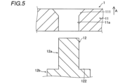
- FIG. 4 is a cross-sectional view showing a step of forming a shaft portion of a segment coil and a through hole of a busbar ring in the method of joining metal members according to the first embodiment;
- FIG. 5 is a cross-sectional view showing a step of inserting the shaft portion of the segment coil into the through-hole of the busbar ring in the method of joining metal members according to the first embodiment
- FIG. 4 is a plan view showing a state in which the shaft portion of the segment coil is inserted into the through hole of the busbar ring in the metal member joining method of the first embodiment
- FIG. 4 is a cross-sectional view showing a step of irradiating a shaft portion of a segment coil with a laser in the method for joining metal members according to the first embodiment
- FIG. 4 is a plan view showing a state in which the axial portion of the segment coil is melted and solidified in the method for joining metal members according to the first embodiment
- FIG. 8 is a cross-sectional view showing a segment coil and a busbar ring that are joined by the method for joining metal members according to the second embodiment; 6 is a flow chart showing a method for joining metal members according to the second embodiment.
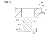
- FIG. 10 is a cross-sectional view showing a step of forming through holes of the shaft portion of the segment coil and the busbar ring in the method of joining metal members according to the second embodiment;
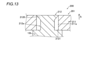
- FIG. 10 is a cross-sectional view showing a step of inserting the shaft portion of the segment coil into the through-hole of the busbar ring in the method for joining metal members according to the second embodiment;
- FIG. 8 is a cross-sectional view showing a step of irradiating a busbar ring with a laser in the method of joining metal members according to the second embodiment.
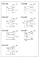
- FIG. 11 is a plan view showing a segment coil and a busbar ring joined by the metal member joining method of the third embodiment; 16A to 16G are plan views showing modified examples of segment coils and bus bar rings joined by the metal member joining method of the third embodiment. It is the flow chart which showed the joining method of the metal member of a 3rd embodiment.
- FIG. 11 is a cross-sectional view showing a segment coil and a busbar ring that are joined by the method for joining metal members according to the fourth embodiment; 19A and 19B are cross-sectional views showing modifications of the segment coil and busbar ring joined by the metal member joining method of the fourth embodiment. It is the flow chart which showed the joining method of the metal member of a 4th embodiment.
- FIG. 11 is a plan view showing a segment coil and a busbar ring joined by the metal member joining method of the fifth embodiment;
- FIG. 11 is a cross-sectional view showing a segment coil and a busbar ring joined by the metal member joining method of the fifth embodiment; 11 is a flow chart showing a method for joining metal members according to a fifth embodiment;
- FIG. 14 is a cross-sectional view showing a step of irradiating the shaft portion of the segment coil with a laser in the method for joining metal members according to the fifth embodiment;
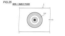
- FIG. 12 is a plan view showing a state in which the axial portion of the segment coil is melted and solidified in the method for joining metal members according to the fifth embodiment;
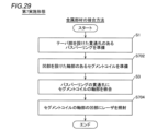
- 11 is a flow chart showing a method for joining metal members according to the sixth embodiment.
- FIG. 20 is a cross-sectional view showing a step of forming through holes of the shaft portion of the segment coil and the busbar ring in the method of joining metal members according to the sixth embodiment;
- FIG. 14 is a cross-sectional view showing a step of irradiating a laser beam onto the elongated portion of the axial portion of the segment coil in the method for joining metal members according to the sixth embodiment; 14 is a flow chart showing a method for joining metal members according to the seventh embodiment.
- FIG. 20 is a cross-sectional view showing a step of forming through holes of the shaft portion of the segment coil and the busbar ring in the method of joining metal members according to the seventh embodiment;
- FIG. 20 is a cross-sectional view showing a step of irradiating a recessed portion of the shaft portion of the segment coil with a laser in the method for joining metal members according to the seventh embodiment;
- FIG. 11 is a modified example of a cross-sectional view showing a segment coil and a busbar ring joined by the method for joining metal members according to the first to seventh embodiments;
- motor 100 includes a stator 1 and a rotor (not shown).
- the stator 1 includes a busbar ring 11 (an example of the "first metal member” and the “busbar” in the claims) and a segment coil 12 (the “second metal member” in the claims). , a “second member” and a “coil”) and a slot 13 .
- the busbar ring 11 is made of aluminum.
- the busbar ring 11 is formed with a through hole 11a for connecting the distal end portion of the segment coil 12 and the busbar ring 11 .
- the through hole 11a penetrates the busbar ring 11 in the thickness direction.
- the through hole 11 a has a tapered portion 111 .
- the tapered portion 111 extends along the through hole 11 a of the busbar ring 11 in the A direction (an example of the “insertion direction” in the claims) in which the shaft portion 12 a of the segment coil 12 is inserted into the through hole 11 a of the busbar ring 11 . It spreads in a direction orthogonal to the A direction toward the tip toward the A direction.
- the segment coil 12 is made of a different kind of metal than the busbar ring 11.
- the segment coil 12 is made of copper.
- the segment coil 12 is provided separately from the busbar ring 11 .
- the segment coil 12 is formed in a bar shape.
- the segment coils 12 are coils inserted through slots 13 provided in the stator 1 .
- the segment coil 12 has a shaft portion 12a.
- the shaft portion 12a is formed by making the distal end portion of the rod-shaped segment coil 12 thinner than the other portion 12b.
- the shaft portion 12a is a coil end of a coil protruding outside the slot 13 of the stator 1 in the C direction (an example of the "axial direction" in the claims).
- the C direction is a direction parallel to the direction along the rotation center axis Rc of the motor 100 .
- the shaft portion 12 a has an engaging portion 121 , a backup portion 122 and a fitting portion 123 .
- the engaging portion 121 is formed by melting the tip portion of the shaft portion 12a. In the A direction, the engaging portion 121 has a tapered shape that widens in a direction orthogonal to the A direction toward the tip of the segment coil 12 toward the A direction. In addition, the engaging portion 121 has a portion that protrudes in the A direction from the tip of the through hole 11a.
- the backup portion 122 is an end surface of the portion 12b other than the shaft portion 12a of the segment coil 12 on the side of the shaft portion 12a. The backup portion 122 is a contact surface that contacts the busbar ring 11 .
- the fitting portion 123 is a portion between the engaging portion 121 and the fitting portion 123 of the segment coil 12 . The fitting portion 123 is a portion that fits into the through hole 11a. The fitting portion 123 is fitted into the through hole 11a by clearance fitting.
- the slot 13 is a recessed groove formed in the inner peripheral surface 1 a of the stator 1 .
- the slot 13 extends along the C direction.
- a portion of the segment coil 12 is arranged in the slot 13 .
- the joining method of metal members is a joining method that can prevent a load from being applied to the segment coil 12 when joining the bus bar ring 11 and the segment coil 12 .
- step S1 a busbar ring 11 having a through hole 11a with a tapered portion 111 is prepared (see FIG. 5). That is, step S1 includes a step of forming the through hole 11a in the metal busbar ring 11, and a step of forming the through hole 11a in the metal busbar ring 11, and expanding in the direction perpendicular to the direction A toward the tip of the throughhole 11a of the busbar ring 11 in the direction A. and forming the tapered portion 111 .
- the through hole 11a is formed by cutting. Note that step S1 is an example of the "first metal member preparing step" in the claims.
- step S2 a segment coil 12 separate from the busbar ring 11 having a shaft portion 12a that can be inserted into the through hole 11a of the busbar ring 11 is prepared (see FIG. 5). That is, in step S2, the segment coil 12 having the shaft portion 12a with the distal end portion of the segment coil 12 thinner than the other portion 12b is prepared. Further, in step S ⁇ b>2 , the segment coil 12 separate from the busbar ring 11 is formed with a shaft portion 12 a that can be inserted into the through hole 11 a of the busbar ring 11 . In step S2, the shaft portion 12a is formed by making the distal end portion of the bar-shaped segment coil 12 thinner than the other portion 12b. The shaft portion 12a is formed by cutting. Note that step S2 is an example of the "second metal member preparing step" in the claims.
- step S3 the shaft portion 12a of the segment coil 12 is fitted into the through hole 11a of the busbar ring 11 (see FIGS. 6 and 7).
- the step S3 includes a step of inserting the shaft portion 12a of the segment coil 12 into the through hole 11a of the busbar ring 11 to fit it.
- step S3 the shaft portion 12a of the segment coil 12 penetrates through the busbar ring 11 until the end face (backup portion 122) of the other portion 12b of the rod-shaped segment coil 12 on the side of the shaft portion 12a and the busbar ring 11 contact each other. It has a step of inserting into the hole 11a.
- step S3 is an example of the "insertion step" in the scope of claims.
- step S4 the shaft portion 12a of the segment coil 12 is irradiated with a laser L (an example of a "high-density energy beam” in the claims) (see FIGS. 8 and 9).
- the laser L is a green laser.
- the shaft portion 12a is melted, and the melted shaft portion 12a flows into the space in which the tapered portion 111 of the through hole 11a is provided.
- the shaft portion 12a melted in the space provided with the tapered portion 111 is cooled by the outside air and solidified (see FIG. 9).
- step S4 is an example of the "joining step" in the scope of claims.
- step S4 in a state where the shaft portion 12a of the segment coil 12 is inserted into the through hole 11a of the busbar ring 11, the segment coil 12 is melted without pressing the segment coil 12, thereby separating the busbar ring 11 and the segment coil.
- 12 is a step of joining. Specifically, in step S4, the segment coil 12 is turned into a high-density energy beam by the laser L as a high-density energy beam without pressing the segment coil 12 by not contacting the segment coil 12 with the fusion zone having the laser L or the like. It is a step of melting and bonding with. Thus, in step S4, the segment coil 12 and the segment coil 12 of the busbar ring 11 are melted.
- step S4 the method for joining metal members ends.
- the metal members are joined together by inserting the shaft portion 12a of the segment coil 12 into the through hole 11a of the busbar ring 11, and without pressing the segment coil 12.
- a step S4 of melting the coil 12 to join the bus bar ring 11 and the segment coil 12 is provided.
- an apparatus for joining metal members can be prevented from becoming large and complicated by the amount of not providing a dedicated clamping device for clamping and fixing the position of the segment coil 12 .
- an increase in the area of the compound (intermetallic compound) generated due to the welding of the segment coil 12 and the busbar ring 11 is suppressed. can do.
- the method for joining metal members includes step S4 in which the segment coil 12 is melted and joined without pressing the segment coil 12 by the laser L (high-density energy beam). contains.
- the segment coil 12 can be melted from a position away from the segment coil 12 by the laser L, so that a load is not applied to the segment coil 12 when the segment coil 12 is melted.
- the method for joining metal members includes step S2 of preparing the segment coil 12 having the shaft portion 12a in which the distal end portion of the bar-shaped segment coil 12 is thinner than the other portions. contains.
- the shaft portion 12a can be formed by cutting, pressing, or the like, so that the processing method for forming the shaft portion 12a can be simplified.
- the method for joining metal members includes the step S4 of melting and joining the segment coil 12 with the laser L as a high-density energy beam without pressing the segment coil 12. contains.
- the segment coil 12 can be melted by a simple method, so that the complication of the device for joining metal members can be suppressed.
- the segment coils 12 are coils inserted through the slots 13 provided in the stator 1 .
- the shaft portion 12a is a coil end of a coil protruding outside the slots 13 of the stator 1 in the C direction.
- the method of joining the metal members is to insert the shaft portion 12a of the segment coil 12 of the stator 1 into the through hole 11a of the bus bar ring 11 of the stator 1, and then, without pressing the segment coil 12 of the stator 1, the stator 1 is joined.
- a step S4 of melting and joining the segment coils 12 is included.
- FIG. 10 a method for joining metal members according to a second embodiment
- a taper portion 2120 is formed on the shaft portion 212a of the segment coil 212, unlike the method for joining metal members according to the first embodiment.
- symbol is attached
- the motor 200 includes a stator 201 and a rotor (not shown).
- the stator 201 includes a busbar ring 211 (an example of the “first metal member” and “busbar” in the claims) and segment coils 212 (“second metal member”, “second member” and “coils” in the claims). ” example).
- the busbar ring 211 is formed with a through hole 211a for connecting the distal end portion of the segment coil 212 and the busbar ring 211 .
- the through hole 211 a has a tapered portion 2111 .
- the segment coil 212 has a shaft portion 212a.
- the shaft portion 212 a has an engaging portion 2121 , a backup portion 122 and a fitting portion 123 .
- the engaging portion 2121 has a tapered shape that widens in a direction orthogonal to the A direction toward the tip of the segment coil 212 in the A direction. Also, in the A direction, the position of the engaging portion 2121 is substantially the same as the position of the tip of the through hole 211a.
- the rest of the configuration of the second embodiment is the same as the configuration of the first embodiment, so the description is omitted.
- the metal member joining method is a joining method that can prevent a load from being applied to the segment coil 212 when joining the bus bar ring 211 and the segment coil 212 .
- step S201 a busbar ring 211 having through holes 211a is prepared (see FIG. 12). That is, step S ⁇ b>201 has a step of forming through holes 211 a in metal busbar ring 211 .
- the through hole 211a is formed by cutting.
- step S202 a segment coil 212 having a tapered shaft portion 212a that can be inserted into the through hole 211a of the busbar ring 211 is prepared (see FIG. 12).
- step S202 the shaft portion 212a having the tapered engaging portion 2121 is formed on the segment coil 212. As shown in FIG.
- the shaft portion 212a is formed by cutting. Note that step S201 is an example of the "first metal member preparing step” in the claims. Moreover, step S202 is an example of the "second metal member preparing step” in the claims.
- step S3 the shaft portion 212a of the segment coil 212 is fitted into the through hole 211a of the busbar ring 211 (see FIG. 13).
- step S204 the vicinity of the through hole 211a of the bus bar ring 211 is irradiated with a laser L (an example of a "high-density energy beam" in the claims) (see FIG. 14).
- the laser L is a green laser.
- step S204 the busbar ring 211 out of the segment coil 212 and the busbar ring 211 is melted.
- step S204 is an example of the "joining step" in the claims.
- the metal members are joined by pressing the segment coil 212 while the shaft portion 212a of the segment coil 212 is inserted into the through hole 211a of the busbar ring 211.
- it includes a step S204 of melting the busbar ring 211 to join the busbar ring 211 and the segment coil 212 together.
- Other effects of the second embodiment are the same as the effects of the first embodiment, so description thereof will be omitted.
- FIG. 15 a method for joining metal members according to the third embodiment will be described with reference to FIGS. 15 to 17.
- a rotation preventing portion 3111 is formed in the through hole 311 a of the busbar ring 311 .
- symbol is attached
- the motor 300 includes a stator 301 and a rotor (not shown).
- the stator 301 includes a busbar ring 311 (an example of the “first metal member” and “busbar” in the claims) and segment coils 12 (“second metal member”, “second member” and “coils” in the claims). ” example).
- the busbar ring 311 is formed with a through hole 311a for connecting the tip portion of the segment coil 12 and the busbar ring 311 .
- the through hole 311a penetrates the busbar ring 311 in the thickness direction.
- the through hole 311a has a detent portion 3111.
- the anti-rotation portion 3111 is configured at the through-hole 311a so as to stop the rotation of the shaft portion 12a with respect to the through-hole 311a.
- the anti-rotation portion 3111 has a non-circular shape in plan view. Specifically, the anti-rotation portion 3111 has a substantially rectangular shape in plan view.
- the anti-rotation portion 3111 has modifications as shown in FIGS. 16A to 16G.
- the anti-rotation portion 3111 shown in FIGS. 16A to 16C is provided in the through hole 311a.
- the anti-rotation portion 3111 shown in FIG. 16A has a substantially elliptical shape in plan view.
- the anti-rotation portion 3111 shown in FIG. 16B has a substantially groove shape in plan view.
- a plurality of substantially groove-shaped detent portions 3111 may be provided in the through hole 311a.
- the anti-rotation portion 3111 shown in FIG. 16C has a plurality (two) of substantially triangular grooves and a plurality (two) of grooves in plan view.
- the anti-rotation portion 3111 shown in FIGS. 16D to 16G is provided in the through hole 311a and the shaft portion 312a.
- the anti-rotation portion 3111 shown in FIG. 16D has a substantially rectangular through hole 311a and a substantially rectangular shaft portion 312a in plan view.
- the anti-rotation portion 3111 shown in FIG. 16E has a substantially elliptical through hole 311a and a substantially rectangular shaft portion 312a in plan view.
- the anti-rotation portion 3111 shown in FIG. 16F has a substantially groove-shaped through hole 311a and a substantially rectangular shaft portion 312a in plan view. It has a substantially groove shape.
- the anti-rotation portion 3111 shown in FIG. 16G has multiple (two) triangular grooves and multiple (two) grooves in plan view. The rest of the configuration of the third embodiment is the same as the configuration of the first embodiment, so the description is omitted.
- the joining method of metal members is a joining method that can prevent a load from being applied to the segment coil 12 when joining the bus bar ring 311 and the segment coil 12 (312).
- step S301 a busbar ring 311 having a through hole 311a provided with a detent portion 3111 is prepared (see FIG. 15). That is, in step S301, a through hole 311a having a detent portion 3111 provided in the busbar ring 311 is formed.
- step S301 is an example of the "first metal member preparing step" in the claims.
- steps S2 to S4 are the same as the contents of steps S2 to S4 in the first embodiment, description thereof will be omitted.
- the method of joining the metal members is such that the shaft portion 12a (312a) of the segment coil 12 (312) is inserted into the through hole 311a of the busbar ring 311, and the segment A step S4 of melting the segment coil 12 (312) and joining the busbar ring 311 and the segment coil 12 (312) without pressing the coil 12 (312a) is provided.
- the segment A step S4 of melting the segment coil 12 (312) and joining the busbar ring 311 and the segment coil 12 (312) without pressing the coil 12 (312a) is provided.
- the rotation of the shaft portion 12a (312a) with respect to the through hole 311a is stopped.
- a step S1 of forming a circular anti-rotation portion 3111 is provided.
- the rotation of the shaft portion 12a (312a) in the through hole 311a can be restricted by the anti-rotation portion 3111, so that the busbar ring 311 and the segment coil 12 (312) are aligned in the rotation direction of the shaft portion 12a (312a).
- Other effects of the third embodiment are the same as the effects of the first embodiment, so description thereof will be omitted.
- the motor 400 includes a stator 401 and a rotor (not shown).
- the stator 401 includes a busbar ring 411 (an example of the “first metal member” and “busbar” in the claims) and segment coils 412 (“second metal member”, “second member” and “segment An example of "coil”).
- the busbar ring 411 has a through hole 411a and a groove portion 411b.
- the groove portion 411b is formed by recessing the inner surface of the through hole 411a in a direction orthogonal to the A direction (an example of the "insertion direction" in the claims).
- the segment coil 412 is made of a different kind of metal than the busbar ring 411. Segment coil 412 is formed in a bar shape.
- the segment coil 412 has a projecting portion 412 a and a fitting portion 123 .
- the protruding portion 412a protrudes in a direction perpendicular to the A direction in a cross section perpendicular to the A direction.
- the projecting portion 412 a may be provided on the entire outer peripheral surface of the segment coil 412 or may be provided on a part of the outer peripheral surface of the segment coil 412 .
- the segment coil 412 is positioned in the A direction by engaging the groove 411b and the protrusion 412a.
- the projecting portion 412a has a modified example as shown in FIGS. 19A and 19B.
- a protruding portion 412a shown in FIG. 19A is formed on the outer peripheral surface of the segment coil 412 in a substantially spiral shape.
- a projecting portion 412a shown in FIG. 19B may be formed on the outer peripheral surface of the segment coil 412 in a substantially tapered shape.
- the rest of the configuration of the fourth embodiment is the same as the configuration of the first embodiment, so the description is omitted.
- the metal member joining method is a joining method that can prevent a load from being applied to the segment coil 412 when joining the bus bar ring 411 and the segment coil 412 .
- step S401 a busbar ring 411 having through holes 411a with grooves 411b is prepared (see FIG. 18). That is, in step S401, the bus bar ring 411 is formed with the through hole 411a having the groove portion 411b.
- Step S401 is a step of forming a groove portion 411b recessed in a direction perpendicular to the direction A in the through hole 411a. Note that step S401 is an example of the "first metal member preparing step" in the claims.
- steps S2 and S3 are the same as the contents of steps S2 and S3 of the first embodiment, description thereof will be omitted.
- step S404 the tip portion (shaft portion) of the segment coil 412 is irradiated with a laser L (an example of a "high-density energy beam” in the claims).
- step S404 is a step of melting the segment coil 412 and pouring a part of the melted segment coil 312 into the groove portion 411b in the through hole 411a. Note that step S404 is an example of the "joining step" in the scope of claims.
- the method of joining the metal members is such that the segment coil 412 is inserted into the through hole 411a of the busbar ring 411 with the distal end portion (shaft portion) of the segment coil 412 being inserted into the through hole 411a.
- a step S4 of joining the busbar ring 411 and the segment coil 412 by melting the segment coil 412 without pressing is provided.
- Other effects of the fourth embodiment are the same as the effects of the first embodiment, so description thereof will be omitted.
- FIG. Specifically, unlike the metal member joining method of the first embodiment, in the metal member joining method of the fifth embodiment, a portion of the shaft portion 512a of the segment coil 512 and a portion of the busbar ring 11 are joined. The laser L is irradiated so as to do.
- symbol is attached
- the motor 500 includes a stator 501 and a rotor (not shown).
- the stator 501 includes a busbar ring 11 (an example of the "first metal member” and “busbar” in the claims) and a segment coil 512 (the "second metal member”, “second member” and “segment (an example of "coil”) and a welded portion 513.
- the segment coil 512 has a shaft portion 512a.
- the shaft portion 512 a has a melt-solidified portion 5121 , a backup portion 122 and a fitting portion 123 .
- the melt-solidified portion 5121 is formed by melting and solidifying the tip portion of the shaft portion 512a.
- the melt-solidified portion 5121 is formed by melting and solidifying the tip portion of the shaft portion 512a.
- the segment coil 512 is engaged with the busbar ring 11 via the melted solidified portion 5121 .
- the melt-solidified portion 5121 has a tapered shape that widens in the direction perpendicular to the direction A toward the tip of the segment coil 512 in the direction A. As shown in FIG. In addition, the melt-solidified portion 5121 has a portion that protrudes in the A direction from the tip of the through hole 11a.
- the backup portion 122 is an end surface of the portion 12b other than the shaft portion 512a of the segment coil 512 on the side of the shaft portion 512a.
- the backup portion 122 is a contact surface that contacts the busbar ring 11 .
- the fitting portion 123 is a portion between the melt-solidified portion 5121 and the fitting portion 123 of the segment coil 512 .
- the fitting portion 123 is a portion that fits into the through hole 11a.
- the fitting portion 123 is fitted into the through hole 11a by clearance fitting.
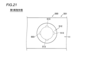
- the welded portion 513 is solidified (welded) in a state in which a portion of the busbar ring 11 and a portion of the segment coil 512 melted by a laser L (an example of a “high-density energy beam” in the claims) are mixed. formed by In other words, the welded portion 513 joins the busbar ring 11 and the segment coil 512 by partially welding instead of entirely. In this way, when viewed from direction A, the busbar ring 11 and the segment coil 512 are joined via a welded portion 513 that is partially welded to the inner peripheral surface of the through hole 11a. As a result, the busbar ring 11 and the segment coil 512 are partially joined via the welded portion 513, so that the rotation of the segment coil 512 is restricted. Thus, the welded portion 513 is a detent portion that restricts the rotation of the segment coil 512 .
- the rest of the configuration of the fifth embodiment is the same as the configuration of the first embodiment, so the description is omitted.
- the metal member joining method is a joining method that can prevent a load from being applied to the segment coil 512 when joining the bus bar ring 11 and the segment coil 512 .
- steps S1 to S3 are the same as those of steps S1 to S3 of the method for joining metal members according to the first embodiment, so description thereof will be omitted.
- the laser L is intermittently radiated across the shaft portion 512a of the segment coil 512 in plan view. That is, in step S504, by irradiating the laser L, both the busbar ring 11 and the segment coil 512 are melted to partially weld and join the busbar ring 11 and the segment coil 512, and the segment coil 512 and the segment coil 512 are welded together. This is the step of melting one of the busbar rings 11 and joining the segment coil 512 and the busbar ring 11 by welding.
- step S504 the busbar ring 11 and the segment coil 512 are joined by welding not wholly but partially. Note that step S504 is an example of the "joining step” in the scope of claims. After step S504, the method for joining metal members ends.
- the method of joining metal members is to press the segment coil 512 while the shaft portion 512a of the segment coil 512 is inserted into the through hole 11a of the busbar ring 11.
- a step S504 of melting the segment coil 512 to join the busbar ring 11 and the segment coil 512 is provided. As a result, it is possible to suppress the enlargement and complication of the device for joining the metal members.
- step S504 the segment coil 512 and the busbar ring 11 are partially melted by irradiating the laser L to melt both the segment coil 512 and the busbar ring 11.
- the segment coil 512 and the busbar ring 11 are joined by welding and melting the segment coil 512 .
- the segment coil 512 and the busbar ring 11 are partially welded (welded portion 513) to restrict the rotation of the shaft portion 512a in the through hole 11a. can be joined so as to prevent them from moving in the rotational direction of the shaft portion 12a.
- the metal member joining structure includes the metal busbar ring 11 having the through hole 11a and the shaft portion 512a inserted into the through hole 11a of the busbar ring 11. , and a segment coil 512 provided separately from the bus bar ring 11 .
- the shaft portion 512a has a melt-solidified portion 5121 having a melt-solidified tip portion.
- the segment coil 512 is engaged with the busbar ring 11 via the melted solidified portion 5121 .
- the busbar ring 11 and the segment coil 512 are joined via a partially welded weld portion 513 .
- the same reference numerals are given to the same configurations as in the first embodiment, and the description thereof is omitted.
- the method of joining the metal members includes the busbar ring 11 (an example of the "first metal member” and “busbar” in the claims) and the segment coil 612 (the "second metal member” and “second member” in the claims). and an example of a “segment coil”).
- steps S1 and S3 are the same as the contents of steps S1 and S3 of the method for joining metal members according to the first embodiment, so description thereof will be omitted.
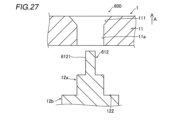
- step S602 a segment coil 612 having a shaft portion 12a with an elongated portion 6121 is prepared (see FIG. 27). That is, in step S602, the segment coil 612 is formed with the shaft portion 12a and the elongated portion 6121.
- Step S602 is a step of forming an elongated portion 6121 by thinning the tip side portion of the shaft portion 12a from the portion to be fitted into the through hole 11a. Note that step S602 is an example of the "second metal member preparing step" in the claims.
- step S604 the elongated portion 6121 of the shaft portion 12a of the segment coil 612 is irradiated with the laser L (see FIG. 28). That is, in step S604, the elongated portion 6121 of the segment coil 12 is melted by irradiating the laser L, and the melted elongated portion 6121 flows into the space provided with the tapered portion 111 of the through hole 11a. Then, the shaft portion 12a melted in the space provided with the tapered portion 111 is cooled by the outside air and solidified. After step S604, the method for joining metal members ends. Note that step S604 is an example of the "bonding step" in the claims.
- the metal members are joined by pressing the segment coil 612 while the shaft portion 12a of the segment coil 612 is inserted into the through hole 11a of the busbar ring 11.
- a step S604 of melting the segment coil 612 to join the busbar ring 11 and the segment coil 612 is provided.
- Other effects of the sixth embodiment are the same as the effects of the first embodiment, so description thereof will be omitted.
- the same reference numerals are given to the same configurations as in the first embodiment, and the description thereof is omitted.
- the method of joining the metal members includes the busbar ring 11 (an example of the "first metal member” and “busbar” in the claims) and the segment coil 712 (the “second metal member” and “second member” in the claims). and an example of a “segment coil”), it is possible to prevent a load from being applied to the segment coil 712 .
- steps S1 and S3 are the same as the contents of steps S1 and S3 of the method for joining metal members according to the first embodiment, so description thereof will be omitted.
- step S702 a segment coil 712 having a shaft portion 712a provided with a concave portion 7121 is prepared (see FIG. 30). That is, in step S702, the segment coil 712 is formed with the shaft portion 712a and the concave portion 7121 (see FIG. 30). That is, step S702 is a step of recessing the axial portion 712a of the segment coil 712 in the direction opposite to the A direction (an example of the “insertion direction” in the claims) to form the recess 7121 . Note that step S702 is an example of the "second metal member preparing step" in the claims.
- step S704 the recess 7121 of the shaft portion 712a of the segment coil 612 is irradiated with the laser L (see FIG. 31). That is, step S704 is a step of joining the segment coil 712 and the bus bar ring 11 by irradiating the recess 7121 with the laser L as a high-density energy beam. As a result, the portion around the concave portion 7121 of the segment coil 712 is melted by irradiation with the laser L, and the melted shaft portion 712a flows into the space in which the tapered portion 111 of the through hole 11a is provided. Then, the shaft portion 712a melted in the space provided with the tapered portion 111 is cooled by the outside air and solidified.
- step S702 is an example of the "joining step" in the claims.
- the metal members are joined by pressing the segment coil 712 while the shaft portion 712a of the segment coil 712 is inserted into the through hole 11a of the busbar ring 11.
- a step S704 of melting the segment coil 712 to join the bus bar ring 11 and the segment coil 712 is provided.
- Other effects of the seventh embodiment are the same as the effects of the first embodiment, so description thereof will be omitted.
- the busbar ring 11 (211, 311, 411: first member) is made of aluminum, but the present invention is not limited to this.
- the first member may be made of metal other than aluminum, resin, or the like.
- the method of joining the members includes a first member preparing step of preparing the first member made of resin and having a through hole.
- the member joining method includes a second member preparing step of preparing a second member made of metal separate from the first member having the shaft portion that can be inserted into the through hole of the first member.
- the joining method of the members includes an inserting step of inserting the shaft portion of the second member into the through hole of the first member.
- the method of joining the members includes inserting the shaft portion of the second member into the through hole of the first member and melting the second member without pressing the second member to join the first member and the second member. It has a bonding step for bonding. As a result, external force is less likely to be applied to the second member, so even if the second member is made of a material with low rigidity, it is not necessary to melt the second member in a position-fixed state in which the second member is sandwiched. As a result, it is possible to obtain a method for joining members that is capable of suppressing an increase in size and complication of a device for joining members by the amount that a dedicated clamping device for sandwiching and fixing the position of the second member is not provided. can.
- the segment coil 12 (212, 412, 512, 612, 712, 812: second metal member) is the busbar ring 11 (211, 311, 411: first metal member).
- the present invention is not limited to this.
- the second metal member may be made of the same metal (for example, copper) as the first metal member.
- the busbar ring 11 (211, 311, 411: first metal member) and the segment coil 12 (212, 412, 512, 612, 712, 812: second metal member) is joined, but the present invention is not limited to this.
- the flat wire coil as the first metal member and the flat wire coil as the second metal member may be joined.
- the shaft portion 12a (212a, 412a, 512a, 712a) of the segment coil 12 is irradiated with the laser L.
- the present invention is not limited to this.
- the shaft portion of the second metal member may be melted by bringing a high-temperature heat source such as a heater into contact with the shaft portion of the second metal member.
- a high-temperature heat source such as a heater
- the high-temperature heat source having a high heat source temperature can melt the segment coil just by slightly contacting the segment coil, so that the load applied to the segment coil when melting the segment coil can be reduced.
- the laser L high-density energy beam
- the high density energy beam may be an electron beam.
- the through holes 11a (211a, 311a, 811a) of (211, 311, 411: first metal member) are arranged coaxially in the A direction (insertion direction)
- the present invention is not limited to In the present invention, the shaft portion of the second metal member and the through hole of the busbar ring do not have to be arranged coaxially in the insertion direction (they may be eccentric).
- the method for joining metal members is such that the tip portion of the rod-shaped segment coil 12 (212, 412, 512, 612, 712, 812: second metal member) is
- step S2 S202, S602, S702
- the present invention is not limited to this.
- the method for joining metal members does not need to include the step of forming the shaft portion by making the distal end portion of the rod-shaped second metal member thinner than the other portions.
- the first metal member and the second metal member may have a joint structure having cross-sectional shapes such as the modifications shown in FIGS. 32A to 32F as examples of joining.
- a through hole 811 a shown in FIG. 32A has an arc-shaped portion 811 .
- a through hole 811 a shown in FIG. 32B has a stepped portion 811 .
- the through hole 811a shown in FIG. 32C does not have a specific shape.
- a through hole 811a shown in FIG. 32D has a stepped portion 811 having an inclined surface.
- a through hole 811a shown in FIG. 32E has a stepped portion 811 having a concave portion. It has an arcuate portion 811 .
- a through hole 811 a shown in FIG. 32F has a key groove 811 .
- the method for joining metal members is applied to the motor 100 (200, 300, 400, 500, 600, 700, 800), but the present invention is applicable to this. is not limited to In the present invention, the method for joining metal members may be applied to other than motors.
- stator 11 211, 311, 411 busbar ring (first metal member, busbar) 11a, 211a, 311a, 411a, 811a through hole 12, 212, 312, 412, 512, 612, 712 segment coil (second metal member, second member, coil) 12a, 212a, 312a, 512a, 712a Shaft portion 12b
- Other portion 13 Slot 121, 2121 Engaging portion 513 Welding portion 3111 Detent portion 5121 Melt-solidified portion L Laser
Landscapes
- Physics & Mathematics (AREA)
- Optics & Photonics (AREA)
- Engineering & Computer Science (AREA)
- Plasma & Fusion (AREA)
- Mechanical Engineering (AREA)
- Laser Beam Processing (AREA)
- Manufacture Of Motors, Generators (AREA)
Abstract
この金属部材の接合方法は、第2金属部材12の軸部12aを第1金属部材11の貫通孔11内に挿入した状態で、第2金属部材12を押圧することなく、第1金属部材11および第2金属部材12のいずれかを溶融させて第1金属部材11および第2金属部材12を接合するステップS4を備える。
Description
この発明は、金属部材の接合方法、部材接合方法および金属部材接合構造に関する。
従来、金属部材の接合方法が知られている。この金属部材の接合方法は、たとえば、特開2018-83329号公報に開示されている。
上記特開2018-83329号公報には、金属製の第1接合部材と、金属製の第2接合部材とを接合する金属部材の接合方法が開示されている。金属部材の接合方法は、第1接合部材に溶着ボスが形成されるステップを備えている。金属部材の接合方法は、溶着ボスを挿入可能な挿入孔が第2接合部材に形成されるステップを備えている。金属部材の接合方法は、溶着ボスが挿入孔に挿入された後、挿入孔から突出した溶着ボスの先端に加熱した熱カシメ用工具が押し付けられるステップを備えている。これにより、上記特開2018-83329号公報の金属部材の接合方法では、熱カシメ用工具の加熱により軟化した溶着ボスが成形されることにより、第1接合部材と、金属製の第2接合部材とが接合される。
しかしながら、上記特開2018-83329号公報の金属部材の接合方法では、挿入孔から突出した溶着ボスの先端に加熱した熱カシメ用工具が押し付けられるステップを行う際、第1接合部材および第2接合部材が剛性の低い材料である場合、熱カシメ用工具の押し付けに起因して溶着ボスが動かないようにするために、第1接合部材および第2接合部材をクランプする(挟み込んで位置固定する)必要がある。この場合、上記特開2018-83329号公報の金属部材の接合方法では、第1接合部材および第2接合部材をクランプする専用のクランプ装置が必要になる。このため、上記特開2018-83329号公報の金属部材の接合方法では、クランプ装置の分だけ、金属部材を接合するための装置が大型化および複雑化するので、金属部材を接合するための装置の大型化および複雑化を抑制することが望まれている。また、第1接合部材および第2接合部材の両方を全体的に溶融させて溶接のみで、第1接合部材と第2接合部材とを接合する場合、第1接合部材と第2接合部材とを溶接させることに起因して生成される化合物(金属間化合物)の面積が広くなってしまうので、化合物に起因して第1接合部材と第2接合部材との接合強度が低下してしまうという問題点もある。
この発明は、上記のような課題を解決するためになされたものであり、この発明の1つの目的は、金属部材を接合するための装置の大型化および複雑化を抑制することが可能な金属部材の接合方法、部材の接合方法および金属部材接合構造を提供することである。
上記目的を達成するために、この発明の第1の局面における金属部材の接合方法は、貫通孔のある金属製の第1金属部材を準備する第1金属部材準備ステップと、第1金属部材の貫通孔に挿入可能な軸部がある第1金属部材とは別個の第2金属部材を準備する第2金属部材準備ステップと、第2金属部材の軸部を第1金属部材の貫通孔内に挿入する挿入ステップと、第2金属部材の軸部を第1金属部材の貫通孔内に挿入した状態で、第2金属部材を押圧することなく、第1金属部材および第2金属部材のいずれかを溶融させて第1金属部材および第2金属部材を接合する接合ステップとを備える。
この発明の第1の局面における金属部材の接合方法では、上記のように、第2金属部材の軸部を第1金属部材の貫通孔内に挿入した状態で、第2金属部材を押圧することなく、第1金属部材および第2金属部材のいずれかを溶融させて第1金属部材および第2金属部材を接合する接合ステップを設ける。これにより、第2金属部材に外力がかかりにくいので、第1金属部材および第2金属部材が剛性の低い材料である場合でも、第2金属部材を挟み込んで位置固定をした状態で第1金属部材および第2金属部材のいずれかを溶融させる必要が無い。その結果、第2金属部材を挟み込んで位置固定する専用のクランプ装置を設けない分だけ、金属部材を接合するための装置の大型化および複雑化を抑制することができる。また、第1金属部材および第2金属部材の両方を全体的に溶融させないので、第1金属部材と第2金属部材とを溶接させることに起因して生成される化合物(金属間化合物)の面積の増大を抑制することができる。その結果、化合物に起因する第1金属部材と第2金属部材との接合強度の低下を抑制することができる。
上記第1の位置の局面による金属部材の接合方法において、好ましくは、接合ステップは、高密度エネルギービームまたは高温度熱源により、第2金属部材を押圧することなく、第1金属部材および第2金属部材のいずれかを溶融させて接合させるステップを含む。
このように構成すれば、高密度エネルギービームにより第2金属部材から離れた位置から第1金属部材および第2金属部材のいずれかを溶融させることができるので、第1金属部材および第2金属部材のいずれかを溶融させる際に第2金属部材に負荷がかからないようにすることができる。また、熱源の温度が高い高温度熱源は、第1金属部材および第2金属部材のいずれかに若干接触しただけで、第1金属部材および第2金属部材のいずれかを溶融させることができるので、第1金属部材および第2金属部材のいずれかを溶融させる際に第2金属部材にかかる負荷を低減することができる。
上記第1の局面による金属部材の接合方法において、好ましくは、第2金属部材準備ステップは、棒状の第2金属部材の先端部分を他の部分よりも細くした軸部がある第2金属部材を準備するステップを含む。
このように構成すれば、切削加工やプレス加工などにより軸部を形成することができるので、軸部を形成するための加工方法を容易にすることができる。
上記第1の局面による金属部材の接合方法において、好ましくは、貫通孔または軸部の少なくとも一方において、貫通孔に対する軸部の回転を止める非円形状の回り止め部を形成するステップをさらに備える。
このように構成すれば、回り止め部により軸部の貫通孔内における回転を規制することができるので、第1金属部材と第2金属部材とを軸部の回転方向において位置決めすることができる。
上記第1の局面による金属部材の接合方法において、好ましくは、接合ステップは、高密度エネルギービームを照射することにより、第1金属部材および第2金属部材の両方を溶融して第1金属部材と第2金属部材とを部分的に溶接により接合するとともに、第1金属部材および第2金属部材のいずれかを溶融させて第1金属部材と第2金属部材とを接合するステップを含む。
このように構成すれば、第1金属部材と第2金属部材とを部分的に溶接した箇所により、軸部の貫通孔内における回転を規制することができるので、第1金属部材と第2金属部材とを軸部の回転方向に移動するのを防止するように接合することができる。
上記高密度エネルギービームを用いる金属部材の接合方法において、好ましくは、接合ステップは、第2金属部材を押圧することなく、第1金属部材および第2金属部材のいずれかを高密度エネルギービームとしてのレーザにより溶融させて接合させるステップを含む。
このように構成すれば、第1金属部材および第2金属部材のいずれかを簡易な方法により溶融させることができるので、金属部材を接合するための装置の複雑化を抑制することができる。
上記第1の局面による金属部材の接合方法において、好ましくは、第2金属部材は、ステータに設けられたスロットに挿通されたコイルであり、軸部は、軸線方向においてステータのスロットの外側に突出したコイルのコイルエンドであり、接合ステップは、第2金属部材としてのステータのコイルの軸部を第1金属部材としてのステータのバスバーの貫通孔内に挿入した状態で、ステータのコイルを押圧することなく、ステータのコイルおよびステータのバスバーのいずれかを溶融させて接合させるステップを含む。
このように構成すれば、ステータのコイルに外力がかかりにくいので、ステータのコイルを挟み込んで位置固定した状態でステータのバスバーおよびステータのコイルのいずれかを溶融させる必要が無い。その結果、ステータのコイルを挟み込んで位置固定する専用のクランプ装置を設けない分だけ、金属部材を接合するための装置の大型化を抑制することができる。
この発明の第2の局面における部材の接合方法は、貫通孔のある樹脂製の第1部材を準備する第1部材準備ステップと、第1部材の貫通孔に挿入可能な軸部がある第1部材とは別個の金属製の第2部材を準備する第2部材準備ステップと、第2部材の軸部を第1部材の貫通孔内に挿入する挿入ステップと、第2部材の軸部を第1部材の貫通孔内に挿入した状態で、第2部材を押圧することなく、第2部材を溶融させて第1部材および第2部材を接合する接合ステップとを備える。
この発明の第2の局面における部材の接合方法では、上記のように、第2部材の軸部を第1部材の貫通孔内に挿入した状態で、第2部材を押圧することなく、第2部材を溶融させて第1部材および第2部材を接合する接合ステップを備える。これにより、第2部材に外力がかかりにくいので、第1部材および第2部材が剛性の低い材料である場合でも、第2部材を挟み込んで位置固定した状態で第2部材を溶融させる必要が無い。その結果、第2部材を挟み込んで位置固定する専用のクランプ装置を設けない分だけ、部材を接合するための装置の大型化および複雑化を抑制することが可能な部材の接合方法を得ることができる。
この発明の第3の局面における金属部材接合構造は、貫通孔が形成された金属製の第1金属部材と、第1金属部材の貫通孔に挿入される軸部を含み、第1金属部材とは別個に設けられた第2金属部材とを備え、軸部は、先端部が溶融凝固された溶融凝固部を有し、第2金属部材は、溶融凝固部を介して、第1金属部材に係合されており、軸部の挿入方向から見て、第1金属部材と、第2金属部材とは、部分的に溶接された溶接部を介して接合されている。
この発明の第3の局面における金属部材接合構造は、上記のように、軸部の挿入方向から見て、第1金属部材と、第2金属部材とは、部分的に溶接された溶接部を介して接合されている。これにより、軸部の貫通孔内における回転を規制することができるので、第1金属部材と第2金属部材とを軸部の回転方向に移動するのを防止するように接合することが可能な金属部材接合構造を得ることができる。
なお、上記第1の局面における金属部材の接合方法において、以下のような構成も考えられる。
(付記項1)
すなわち、上記一の局面による金属部材の接合方法において、第1金属部材の貫通孔の先端に挿入方向に向かうにしたがって挿入方向に直交する方向に広がるテーパ部を形成するステップをさらに備え、接合ステップは、第2金属部材を溶融して貫通孔におけるテーパ部に溶融した第2接合部材の一部を流し込むステップを含む。
すなわち、上記一の局面による金属部材の接合方法において、第1金属部材の貫通孔の先端に挿入方向に向かうにしたがって挿入方向に直交する方向に広がるテーパ部を形成するステップをさらに備え、接合ステップは、第2金属部材を溶融して貫通孔におけるテーパ部に溶融した第2接合部材の一部を流し込むステップを含む。
このように構成すれば、溶融した第2金属部材が貫通孔の奥に流れ込みやすくすることができるので、第2金属部材と貫通孔との間に溶融した第2金属部材を容易に満たすことができる。
(付記項2)
上記第2金属部材準備ステップを備える金属部材の接合方法において、挿入ステップは、棒状の第2金属部材の他の部分の軸部側の端面と、第1金属部材とが当接するまで、第2金属部材の軸部を第1金属部材の貫通孔に挿入するステップを含む。
上記第2金属部材準備ステップを備える金属部材の接合方法において、挿入ステップは、棒状の第2金属部材の他の部分の軸部側の端面と、第1金属部材とが当接するまで、第2金属部材の軸部を第1金属部材の貫通孔に挿入するステップを含む。
このように構成すれば、棒状の第2金属部材の他の部分の軸部側の端面と、貫通孔に溶融して凝固した第2金属部材の軸部とにより第1金属部材を挟み込むことにより、第1金属部材と第2金属部材とを接合することができる。その結果、棒状の第2金属部材の他の部分の軸部側の端面と、貫通孔に溶融して凝固した第2金属部材の軸部とにより第1金属部材を挟み込むことにより第1金属部材と第2金属部材とが接合されるので、第1金属部材と第2金属部材とを強固に接合することができる。
(付記項3)
上記第1の局面による金属部材の接合方法において、第1金属部材準備ステップは、第2金属部材の軸部を第1金属部材の貫通孔内に挿入する挿入方向に直交する方向に窪む溝部を貫通孔に形成するステップをさらに備え、接合ステップは、第2金属部材を溶融して貫通孔における溝部に溶融した第2金属部材の一部を流し込むステップを含む。
上記第1の局面による金属部材の接合方法において、第1金属部材準備ステップは、第2金属部材の軸部を第1金属部材の貫通孔内に挿入する挿入方向に直交する方向に窪む溝部を貫通孔に形成するステップをさらに備え、接合ステップは、第2金属部材を溶融して貫通孔における溝部に溶融した第2金属部材の一部を流し込むステップを含む。
このように構成すれば、溝部において凝固した第2金属部材の一部により、第1金属部材と第2金属部材とを挿入方向および挿入方向とは逆方向の両方において位置決めすることができるので、挿入方向および挿入方向とは逆方向の各々の位置決めする構造を第1金属部材および第2金属部材に分けて形成する場合と比較して、第2金属部材の加工を容易にすることができる。
(付記項4)
上記他の部分よりも細い軸部を形成するステップを備える金属部材の接合方法において、挿入ステップは、第2金属部材の軸部を第1金属部材の貫通孔内に挿入して嵌合させるステップを含み、第2金属部材準備ステップは、軸部において貫通孔に嵌合させる部分よりも先端側の部分を細くすることにより細長部を形成するステップを含む。
上記他の部分よりも細い軸部を形成するステップを備える金属部材の接合方法において、挿入ステップは、第2金属部材の軸部を第1金属部材の貫通孔内に挿入して嵌合させるステップを含み、第2金属部材準備ステップは、軸部において貫通孔に嵌合させる部分よりも先端側の部分を細くすることにより細長部を形成するステップを含む。
このように構成すれば、細長部は他の部分よりも細くより容易に溶融させることができるので、軸部を溶融させる工程の効率を向上させることができる。
(付記項5)
上記高密度エネルギービームを用いる金属部材の接合方法において、第2金属部材準備ステップは、第2金属部材の軸部を第1金属部材の貫通孔内に挿入する挿入方向側の端面を挿入方向とは逆方向に窪ませて形成された凹部を含み、接合ステップは、高密度エネルギービームとしてのレーザを凹部に照射することにより第2金属部材を接合させるステップを含む。
上記高密度エネルギービームを用いる金属部材の接合方法において、第2金属部材準備ステップは、第2金属部材の軸部を第1金属部材の貫通孔内に挿入する挿入方向側の端面を挿入方向とは逆方向に窪ませて形成された凹部を含み、接合ステップは、高密度エネルギービームとしてのレーザを凹部に照射することにより第2金属部材を接合させるステップを含む。
このように構成すれば、第2金属部材の凹部内部においてレーザを乱反射させることができるので、レーザが有するエネルギーを第2金属部材に確実に吸収させることができる。その結果、第2金属部材に対する吸収率が低いレーザを用いた場合でも、第2金属部材を溶融させることができる。
以下、本発明の実施形態を図面に基づいて説明する。
[第1実施形態]
図1~図9を参照して、金属部材の接合方法の構成について説明する。
図1~図9を参照して、金属部材の接合方法の構成について説明する。
図1に示すように、モータ100に設けられるステータ1の構成について説明する。具体的には、モータ100は、ステータ1と、ロータ(図示せず)とを備えている。
図1~図3に示すように、ステータ1は、バスバーリング11(請求の範囲の「第1金属部材」および「バスバー」の一例)と、セグメントコイル12(請求の範囲の「第2金属部材」、「第2部材」および「コイル」の一例)と、スロット13とを含んでいる。バスバーリング11は、アルミニウムにより形成されている。
図2および図3に示すように、バスバーリング11には、セグメントコイル12の先端部と、バスバーリング11とを接続するための貫通孔11aが形成されている。貫通孔11aは、バスバーリング11を厚み方向に貫通している。貫通孔11aは、テーパ部111を有している。テーパ部111は、セグメントコイル12の後述する軸部12aをバスバーリング11の貫通孔11a内に挿入するA方向(請求の範囲の「挿入方向」の一例)において、バスバーリング11の貫通孔11aの先端にA方向に向かうにしたがってA方向に直交する方向に広がっている。
セグメントコイル12は、バスバーリング11とは異なる種類の金属により形成されている。セグメントコイル12は、銅により形成されている。セグメントコイル12は、バスバーリング11とは別個に設けられている。セグメントコイル12は、棒状に形成されている。セグメントコイル12は、ステータ1に設けられたスロット13に挿通されたコイルである。セグメントコイル12は、軸部12aを有している。軸部12aは、棒状のセグメントコイル12の先端部分を他の部分12bよりも細くすることにより形成されている。軸部12aは、C方向(請求の範囲の「軸線方向」の一例)においてステータ1のスロット13の外側に突出したコイルのコイルエンドである。C方向は、モータ100の回転中心軸線Rcに沿った方向に平行な方向である。
軸部12aは、係合部121と、バックアップ部122と、嵌合部123とを有している。
係合部121は、軸部12aの先端部を溶融させることにより形成されている。係合部121は、A方向において、セグメントコイル12の先端にA方向に向かうにしたがってA方向に直交する方向に広がるテーパ形状を有している。また、係合部121は、A方向において、貫通孔11aの先端よりもA方向側に突出する部分を有している。バックアップ部122は、セグメントコイル12の軸部12a以外の他の部分12bの軸部12a側の端面である。バックアップ部122は、バスバーリング11と当接する当接面である。嵌合部123は、セグメントコイル12のうちの係合部121と嵌合部123との間の部分である。嵌合部123は、貫通孔11aに嵌合する部分である。嵌合部123は、貫通孔11aに対して隙間嵌めにより嵌合されている。
スロット13は、ステータ1の内周面1aに窪んで形成された溝である。スロット13は、C方向に沿って延びている。スロット13には、セグメントコイル12の一部分が配置されている。
(金属部材の接合方法)
以下に、図4~図9を参照して、第1実施形態の金属部材の接合方法について説明する。金属部材の接合方法は、バスバーリング11と、セグメントコイル12とを接合する際、セグメントコイル12に負荷がかからないようにすることが可能な接合方法である。
以下に、図4~図9を参照して、第1実施形態の金属部材の接合方法について説明する。金属部材の接合方法は、バスバーリング11と、セグメントコイル12とを接合する際、セグメントコイル12に負荷がかからないようにすることが可能な接合方法である。
ステップS1において、テーパ部111を設けた貫通孔11aのあるバスバーリング11を準備する(図5を参照)。すなわち、ステップS1は、金属製のバスバーリング11に貫通孔11aを形成するステップと、A方向において、バスバーリング11の貫通孔11aの先端にA方向に向かうにしたがってA方向に直交する方向に広がるテーパ部111を形成するステップとを有している。貫通孔11aは、切削加工により形成される。なお、ステップS1は、請求の範囲の「第1金属部材準備ステップ」の一例である。
ステップS2において、バスバーリング11の貫通孔11aに挿入可能な軸部12aがあるバスバーリング11とは別個のセグメントコイル12を準備する(図5を参照)。すなわち、ステップS2では、セグメントコイル12の先端部分を他の部分12bよりも細くした軸部12aがあるセグメントコイル12が準備される。また、ステップS2では、バスバーリング11とは別個のセグメントコイル12に、バスバーリング11の貫通孔11aに挿入可能な軸部12aが形成される。ステップS2では、棒状のセグメントコイル12の先端部分を他の部分12bよりも細くすることにより軸部12aが形成される。軸部12aは、切削加工により形成される。なお、ステップS2は、請求の範囲の「第2金属部材準備ステップ」の一例である。
ステップS3において、バスバーリング11の貫通孔11aにセグメントコイル12の軸部12aが嵌合される(図6および図7を参照)。ステップS3は、セグメントコイル12の軸部12aをバスバーリング11の貫通孔11a内に挿入して嵌合させるステップを有している。ステップS3は、棒状のセグメントコイル12の他の部分12bの軸部12a側の端面(バックアップ部122)と、バスバーリング11とが当接するまで、セグメントコイル12の軸部12aをバスバーリング11の貫通孔11aに挿入するステップを有している。なお、ステップS3は、請求の範囲の「挿入ステップ」の一例である。
ステップS4において、セグメントコイル12の軸部12aにレーザL(請求の範囲の「高密度エネルギービーム」の一例)が照射される(図8および図9を参照)。ここで、レーザLは、グリーンレーザである。これにより、軸部12aが溶融するとともに、貫通孔11aのテーパ部111が設けられた空間に溶融した軸部12aが流れ込む。そして、テーパ部111が設けられた空間に溶融した軸部12aが、外気により冷却されて凝固する(図9を参照)。なお、ステップS4は、請求の範囲の「接合ステップ」の一例である。
すなわち、ステップS4は、セグメントコイル12の軸部12aをバスバーリング11の貫通孔11a内に挿入した状態で、セグメントコイル12を押圧することなく、セグメントコイル12を溶融させてバスバーリング11およびセグメントコイル12を接合するステップである。具体的には、ステップS4は、レーザLなどを有する溶融部と、セグメントコイル12とを当接させないことにより、セグメントコイル12を押圧することなく、セグメントコイル12を高密度エネルギービームとしてのレーザLにより溶融させて接合させるステップである。このように、ステップS4では、セグメントコイル12およびバスバーリング11のうちのセグメントコイル12が溶融されている。
ステップS4の後、金属部材の接合方法は終了する。
(第1実施形態の効果)
第1実施形態では、以下のような効果を得ることができる。
第1実施形態では、以下のような効果を得ることができる。
第1実施形態では、上記のように、金属部材の接合方法は、セグメントコイル12の軸部12aをバスバーリング11の貫通孔11a内に挿入した状態で、セグメントコイル12を押圧することなく、セグメントコイル12を溶融させてバスバーリング11およびセグメントコイル12を接合するステップS4を備えている。これにより、セグメントコイル12に外力がかかりにくいので、セグメントコイル12およびバスバーリング11が剛性の低い材料である場合でも、セグメントコイル12を挟み込んで位置固定した状態でセグメントコイル12を溶融させる必要が無い。この結果、セグメントコイル12を挟み込んで位置固定する専用のクランプ装置を設けない分だけ、金属部材を接合するための装置の大型化および複雑化を抑制することができる。また、セグメントコイル12およびバスバーリング11の両方を全体的に溶融させないので、セグメントコイル12とバスバーリング11とを溶接させることに起因して生成される化合物(金属間化合物)の面積の増大を抑制することができる。この結果、化合物に起因するセグメントコイル12とバスバーリング11との接合強度の低下を抑制することができる。
また、第1実施形態では、上記のように、金属部材の接合方法は、レーザL(高密度エネルギービーム)により、セグメントコイル12を押圧することなく、セグメントコイル12を溶融させて接合させるステップS4を含んでいる。これにより、レーザLによりセグメントコイル12から離れた位置からセグメントコイル12を溶融させることができるので、セグメントコイル12を溶融させる際にセグメントコイル12に負荷がかからないようにすることができる。
また、第1実施形態では、上記のように、金属部材の接合方法は、棒状のセグメントコイル12の先端部分を他の部分よりも細くした軸部12aがあるセグメントコイル12を準備するステップS2を含んでいる。これにより、切削加工やプレス加工などにより軸部12aを形成することができるので、軸部12aを形成するための加工方法を容易にすることができる。
また、第1実施形態では、上記のように、金属部材の接合方法は、セグメントコイル12を押圧することなく、セグメントコイル12を高密度エネルギービームとしてのレーザLにより溶融させて接合させるステップS4を含んでいる。これにより、セグメントコイル12を簡易な方法により溶融させることができるので、金属部材を接合するための装置の複雑化を抑制することができる。
また、第1実施形態では、上記のように、セグメントコイル12は、ステータ1に設けられたスロット13に挿通されたコイルである。軸部12aは、C方向においてステータ1のスロット13の外側に突出したコイルのコイルエンドである。金属部材の接合方法は、ステータ1のセグメントコイル12の軸部12aをステータ1のバスバーリング11の貫通孔11a内に挿入した状態で、ステータ1のセグメントコイル12を押圧することなく、ステータ1のセグメントコイル12を溶融させて接合させるステップS4を含んでいる。これにより、ステータ1のセグメントコイル12に外力がかかりにくいので、ステータ1のセグメントコイル12を挟み込んで位置固定した状態でステータ1のセグメントコイル12を溶融させる必要が無い。この結果、ステータ1のセグメントコイル12を挟み込んで位置固定する専用のクランプ装置を設けない分だけ、金属部材を接合するための装置の大型化を抑制することができる。
[第2実施形態]
次に、図10~図14を参照して、第2実施形態の金属部材の接合方法について説明する。詳細には、第1実施形態の金属部材の接合方法とは異なり、第2実施形態の金属部材の接合方法では、セグメントコイル212の軸部212aにテーパ部2120が形成されている。なお、第2実施形態において、上記第1実施形態と同様の構成に関しては、同じ符号を付して説明を省略する。
次に、図10~図14を参照して、第2実施形態の金属部材の接合方法について説明する。詳細には、第1実施形態の金属部材の接合方法とは異なり、第2実施形態の金属部材の接合方法では、セグメントコイル212の軸部212aにテーパ部2120が形成されている。なお、第2実施形態において、上記第1実施形態と同様の構成に関しては、同じ符号を付して説明を省略する。
図10に示すように、モータ200は、ステータ201と、ロータ(図示せず)とを備えている。
ステータ201は、バスバーリング211(請求の範囲の「第1金属部材」および「バスバー」の一例)と、セグメントコイル212(請求の範囲の「第2金属部材」、「第2部材」および「コイル」の一例)とを含んでいる。
バスバーリング211には、セグメントコイル212の先端部と、バスバーリング211とを接続するための貫通孔211aが形成されている。貫通孔211aは、テーパ部2111を有している。
セグメントコイル212は、軸部212aを有している。軸部212aは、係合部2121と、バックアップ部122と、嵌合部123とを有している。
係合部2121は、A方向において、セグメントコイル212の先端にA方向に向かうにしたがってA方向に直交する方向に広がるテーパ形状を有している。また、A方向において、係合部2121の位置は、貫通孔211aの先端の位置と略同じである。なお、第2実施形態のその他の構成は、第1実施形態の構成と同様であるので説明を省略する。
(金属部材の接合方法)
以下に、図11~図14を参照して、第2実施形態の金属部材の接合方法について説明する。金属部材の接合方法は、バスバーリング211と、セグメントコイル212とを接合する際、セグメントコイル212に負荷がかからないようにすることが可能な接合方法である。
以下に、図11~図14を参照して、第2実施形態の金属部材の接合方法について説明する。金属部材の接合方法は、バスバーリング211と、セグメントコイル212とを接合する際、セグメントコイル212に負荷がかからないようにすることが可能な接合方法である。
ステップS201において、貫通孔211aのあるバスバーリング211を準備する(図12を参照)。すなわち、ステップS201は、金属製のバスバーリング211に貫通孔211aを形成するステップを有している。貫通孔211aは、切削加工により形成される。ステップS202において、バスバーリング211の貫通孔211aに挿入可能なテーパ形状の軸部212aがあるセグメントコイル212を準備する(図12を参照)。ステップS202において、セグメントコイル212にテーパ形状の係合部2121を有する軸部212aが形成される。軸部212aは、切削加工により形成される。なお、ステップS201は、請求の範囲の「第1金属部材準備ステップ」の一例である。また、ステップS202は、請求の範囲の「第2金属部材準備ステップ」の一例である。
ステップS3において、バスバーリング211の貫通孔211aにセグメントコイル212の軸部212aが嵌合される(図13を参照)。ステップS204において、バスバーリング211の貫通孔211aの近傍にレーザL(請求の範囲の「高密度エネルギービーム」の一例)が照射される(図14を参照)。ここで、レーザLは、グリーンレーザである。これにより、バスバーリング211の貫通孔211aの近傍の部分が溶融するとともに、貫通孔211aと軸部212aとの間に設けられた空間に溶融したバスバーリング211が流れ込む。そして、貫通孔211aと軸部212aとの間に設けられた空間に溶融したバスバーリング211が、外気により冷却されて凝固する(図10を参照)。このように、ステップS204では、セグメントコイル212およびバスバーリング211のうちのバスバーリング211が溶融されている。ステップS204の後、金属部材の接合方法は終了する。なお、ステップS204は、請求の範囲の「接合ステップ」の一例である。
(第2実施形態の効果)
第2実施形態では、以下のような効果を得ることができる。
第2実施形態では、以下のような効果を得ることができる。
第2実施形態では、第1実施形態と同様に、金属部材の接合方法は、セグメントコイル212の軸部212aをバスバーリング211の貫通孔211a内に挿入した状態で、セグメントコイル212を押圧することなく、バスバーリング211を溶融させてバスバーリング211およびセグメントコイル212を接合するステップS204を備えている。これにより、金属部材を接合するための装置の大型化および複雑化を抑制することができる。なお、第2実施形態のその他の効果は、第1実施形態の効果と同様であるので説明を省略する。
[第3実施形態]
次に、図15~図17を参照して、第3実施形態の金属部材の接合方法について説明する。詳細には、第1実施形態の金属部材の接合方法とは異なり、第3実施形態の金属部材の接合方法では、バスバーリング311の貫通孔311aに回り止め部3111が形成されている。なお、第3実施形態において、上記第1実施形態と同様の構成に関しては、同じ符号を付して説明を省略する。
次に、図15~図17を参照して、第3実施形態の金属部材の接合方法について説明する。詳細には、第1実施形態の金属部材の接合方法とは異なり、第3実施形態の金属部材の接合方法では、バスバーリング311の貫通孔311aに回り止め部3111が形成されている。なお、第3実施形態において、上記第1実施形態と同様の構成に関しては、同じ符号を付して説明を省略する。
図15に示すように、モータ300は、ステータ301と、ロータ(図示せず)とを備えている。
ステータ301は、バスバーリング311(請求の範囲の「第1金属部材」および「バスバー」の一例)と、セグメントコイル12(請求の範囲の「第2金属部材」、「第2部材」および「コイル」の一例)とを含んでいる。
図15に示すように、バスバーリング311には、セグメントコイル12の先端部と、バスバーリング311とを接続するための貫通孔311aが形成されている。貫通孔311aは、バスバーリング311を厚み方向に貫通している。貫通孔311aは、回り止め部3111を有している。回り止め部3111は、貫通孔311aにおいて、貫通孔311aに対する軸部12aの回転を止めるように構成されている。回り止め部3111は、平面視において、非円形状を有している。具体的には、回り止め部3111は、平面視において、略矩形形状を有している。
また、回り止め部3111は、図16A~図16Gに示すような変形例を有している。
図16A~図16Cに示す回り止め部3111は、貫通孔311aに設けられている。図16Aに示す回り止め部3111は、平面視において、略楕円形状を有している。図16Bに示す回り止め部3111は、平面視において、略溝形状を有している。なお、略溝形状の回り止め部3111は、貫通孔311aに複数設けられていてもよい。図16Cに示す回り止め部3111は、平面視において、複数(2つ)の略三角形形状の溝、および、複数(2つ)の溝を有している。
図16D~図16Gに示す回り止め部3111は、貫通孔311aおよび軸部312aに設けられている。図16Dに示す回り止め部3111は、平面視において、略矩形形状の貫通孔311a、および、略矩形形状の軸部312aを有している。図16Eに示す回り止め部3111は、平面視において、略楕円形状の貫通孔311a、および、略矩形形状の軸部312aを有している。図16Fに示す回り止め部3111は、平面視において、略溝形状の貫通孔311a、および、略矩形形状の軸部312aを有している。略溝形状を有している。図16Gに示す回り止め部3111は、平面視において、複数(2つ)の三角形形状の溝、および、複数(2つ)の溝を有している。なお、第3実施形態のその他の構成は、第1実施形態の構成と同様であるので説明を省略する。
(金属部材の接合方法)
以下に、図17を参照して、第3実施形態の金属部材の接合方法について説明する。金属部材の接合方法は、バスバーリング311と、セグメントコイル12(312)とを接合する際、セグメントコイル12に負荷がかからないようにすることが可能な接合方法である。
以下に、図17を参照して、第3実施形態の金属部材の接合方法について説明する。金属部材の接合方法は、バスバーリング311と、セグメントコイル12(312)とを接合する際、セグメントコイル12に負荷がかからないようにすることが可能な接合方法である。
ステップS301において、回り止め部3111を設けた貫通孔311aのあるバスバーリング311を準備する(図15を参照)。すなわち、ステップS301において、バスバーリング311に回り止め部3111を設けた貫通孔311aが形成される。なお、ステップS301は、請求の範囲の「第1金属部材準備ステップ」の一例である。ここで、ステップS2~ステップS4の内容は、第1実施形態のステップS2~ステップS4の内容と同じであるので、説明を省略する。
(第3実施形態の効果)
第3実施形態では、以下のような効果を得ることができる。
第3実施形態では、以下のような効果を得ることができる。
第3実施形態では、第1実施形態と同様に、金属部材の接合方法は、セグメントコイル12(312)の軸部12a(312a)をバスバーリング311の貫通孔311a内に挿入した状態で、セグメントコイル12(312a)を押圧することなく、セグメントコイル12(312)を溶融させてバスバーリング311およびセグメントコイル12(312)を接合するステップS4を備えている。これにより、金属部材を接合するための装置の大型化および複雑化を抑制することができる。
また、第3実施形態では、上記のように、金属部材の接合方法は、貫通孔311aまたは軸部12a(312a)の少なくとも一方において、貫通孔311aに対する軸部12a(312a)の回転を止める非円形状の回り止め部3111を形成するステップS1を備えている。これにより、回り止め部3111により軸部12a(312a)の貫通孔311a内における回転を規制することができるので、バスバーリング311とセグメントコイル12(312)とを軸部12a(312a)の回転方向において位置決めすることができる。なお、第3実施形態のその他の効果は、第1実施形態の効果と同様であるので説明を省略する。
[第4実施形態]
次に、図18~図20を参照して、第4実施形態の金属部材の接合方法について説明する。詳細には、第1実施形態の金属部材の接合方法とは異なり、第4実施形態の金属部材の接合方法では、セグメントコイル412にバックアップ部が形成されていない。なお、第4実施形態において、上記第1実施形態と同様の構成に関しては、同じ符号を付して説明を省略する。
次に、図18~図20を参照して、第4実施形態の金属部材の接合方法について説明する。詳細には、第1実施形態の金属部材の接合方法とは異なり、第4実施形態の金属部材の接合方法では、セグメントコイル412にバックアップ部が形成されていない。なお、第4実施形態において、上記第1実施形態と同様の構成に関しては、同じ符号を付して説明を省略する。
図18に示すように、モータ400は、ステータ401と、ロータ(図示せず)とを備えている。
ステータ401は、バスバーリング411(請求の範囲の「第1金属部材」および「バスバー」の一例)と、セグメントコイル412(請求の範囲の「第2金属部材」、「第2部材」および「セグメントコイル」の一例)とを含んでいる。
バスバーリング411は、貫通孔411aと、溝部411bとを有している。溝部411bは、貫通孔411aの内側面をA方向(請求の範囲の「挿入方向」の一例)に直交する方向に窪んで形成されている。
セグメントコイル412は、バスバーリング411とは異なる種類の金属により設けられている。セグメントコイル412は、棒状に形成されている。セグメントコイル412は、突出部412aと、嵌合部123とを有している。突出部412aは、A方向に直交する方向の断面において、A方向に直交する方向に突出している。突出部412aは、セグメントコイル412の外周面の全周に設けられていてもよいし、セグメントコイル412の外周面の一部に設けられていてもよい。セグメントコイル412は、溝部411bと、突出部412aとが係合することにより、A方向に位置決めされている。
また、突出部412aは、図19Aおよび図19Bに示すような変形例を有している。
図19Aに示す突出部412aは、セグメントコイル412の外周面に略螺旋状に形成されている。図19Bに示す突出部412aは、セグメントコイル412の外周面に略先細り状に形成されていてもよい。なお、第4実施形態のその他の構成は、第1実施形態の構成と同様であるので説明を省略する。
(金属部材の接合方法)
以下に、図20を参照して、第4実施形態の金属部材の接合方法について説明する。金属部材の接合方法は、バスバーリング411と、セグメントコイル412とを接合する際、セグメントコイル412に負荷がかからないようにすることが可能な接合方法である。
以下に、図20を参照して、第4実施形態の金属部材の接合方法について説明する。金属部材の接合方法は、バスバーリング411と、セグメントコイル412とを接合する際、セグメントコイル412に負荷がかからないようにすることが可能な接合方法である。
ステップS401において、溝部411bを設けた貫通孔411aのあるバスバーリング411を準備する(図18を参照)。すなわち、ステップS401において、バスバーリング411に溝部411bを設けた貫通孔411aが形成される。ステップS401は、A方向に直交する方向に窪む溝部411bを貫通孔411aに形成するステップである。なお、ステップS401は、請求の範囲の「第1金属部材準備ステップ」の一例である。ここで、ステップS2およびステップS3の内容は、第1実施形態のステップS2およびステップS3の内容と同じであるので、説明を省略する。
ステップS404において、セグメントコイル412の先端部分(軸部)にレーザL(請求の範囲の「高密度エネルギービーム」の一例)が照射される。ここで、ステップS404は、セグメントコイル412を溶融して貫通孔411aにおける溝部411bに溶融したセグメントコイル312の一部を流し込むステップである。なお、ステップS404は、請求の範囲の「接合ステップ」の一例である。
(第4実施形態の効果)
第4実施形態では、以下のような効果を得ることができる。
第4実施形態では、以下のような効果を得ることができる。
第4実施形態では、第1実施形態と同様に、金属部材の接合方法は、セグメントコイル412の先端部分(軸部)をバスバーリング411の貫通孔411a内に挿入した状態で、セグメントコイル412を押圧することなく、セグメントコイル412を溶融させてバスバーリング411およびセグメントコイル412を接合するステップS4を備えている。これにより、金属部材を接合するための装置の大型化および複雑化を抑制することができる。なお、第4実施形態のその他の効果は、第1実施形態の効果と同様であるので説明を省略する。
[第5実施形態]
次に、図21~図25を参照して、第5実施形態の金属部材の接合方法について説明する。詳細には、第1実施形態の金属部材の接合方法とは異なり、第5実施形態の金属部材の接合方法では、セグメントコイル512の軸部512aの一部と、バスバーリング11の一部分とを接合するように、レーザLが照射される。なお、第5実施形態において、上記第1実施形態と同様の構成に関しては、同じ符号を付して説明を省略する。
次に、図21~図25を参照して、第5実施形態の金属部材の接合方法について説明する。詳細には、第1実施形態の金属部材の接合方法とは異なり、第5実施形態の金属部材の接合方法では、セグメントコイル512の軸部512aの一部と、バスバーリング11の一部分とを接合するように、レーザLが照射される。なお、第5実施形態において、上記第1実施形態と同様の構成に関しては、同じ符号を付して説明を省略する。
図21および図22に示すように、モータ500は、ステータ501と、ロータ(図示せず)とを備えている。
ステータ501は、バスバーリング11(請求の範囲の「第1金属部材」および「バスバー」の一例)と、セグメントコイル512(請求の範囲の「第2金属部材」、「第2部材」および「セグメントコイル」の一例)と、溶接部513とを含んでいる。
セグメントコイル512は、軸部512aを有している。軸部512aは、溶融凝固部5121と、バックアップ部122と、嵌合部123とを有している。溶融凝固部5121は、軸部512aの先端部が溶融凝固されることにより形成されている。
溶融凝固部5121は、軸部512aの先端部を溶融凝固させることにより形成されている。セグメントコイル512は、溶融凝固部5121を介して、バスバーリング11に係合されている。溶融凝固部5121は、A方向において、セグメントコイル512の先端にA方向に向かうにしたがってA方向に直交する方向に広がるテーパ形状を有している。また、溶融凝固部5121は、A方向において、貫通孔11aの先端よりもA方向側に突出する部分を有している。バックアップ部122は、セグメントコイル512の軸部512a以外の他の部分12bの軸部512a側の端面である。バックアップ部122は、バスバーリング11と当接する当接面である。嵌合部123は、セグメントコイル512のうちの溶融凝固部5121と嵌合部123との間の部分である。嵌合部123は、貫通孔11aに嵌合する部分である。嵌合部123は、貫通孔11aに対して隙間嵌めにより嵌合されている。
溶接部513は、レーザL(請求の範囲の「高密度エネルギービーム」の一例)により溶融したバスバーリング11の一部およびセグメントコイル512の一部が混合された状態で凝固する(溶接する)ことによって形成されている。すなわち、溶接部513は、バスバーリング11とセグメントコイル512とを全体的にではなく部分的に溶接することにより接合している。このように、A方向から見て、バスバーリング11と、セグメントコイル512とは、貫通孔11aの内周面において部分的に溶接された溶接部513を介して接合されている。これにより、バスバーリング11と、セグメントコイル512とが部分的に溶接部513を介して接合されるので、セグメントコイル512の回転が規制される。このように、溶接部513は、セグメントコイル512の回転を規制する回り止め部である。なお、第5実施形態のその他の構成は、第1実施形態の構成と同様であるので説明を省略する。
(金属部材の接合方法)
以下に、図23~図25を参照して、金属部材の接合方法について説明する。金属部材の接合方法は、バスバーリング11と、セグメントコイル512とを接合する際、セグメントコイル512に負荷がかからないようにすることが可能な接合方法である。
以下に、図23~図25を参照して、金属部材の接合方法について説明する。金属部材の接合方法は、バスバーリング11と、セグメントコイル512とを接合する際、セグメントコイル512に負荷がかからないようにすることが可能な接合方法である。
ステップS1~ステップS3の内容は、第1実施形態の金属部材の接合方法のステップS1~ステップS3と同じ内容であるので、説明は省略する。ステップS504において、平面視において、セグメントコイル512の軸部512aを横切るように断続的にレーザLが照射される。すなわち、ステップS504は、レーザLを照射することにより、バスバーリング11およびセグメントコイル512の両方を溶融してバスバーリング11とセグメントコイル512とを部分的に溶接して接合するとともに、セグメントコイル512およびバスバーリング11のいずれかを溶融させてセグメントコイル512とバスバーリング11とを溶接により接合するステップである。このように、ステップS504では、バスバーリング11とセグメントコイル512とが、全体的にではなく部分的に溶接することにより接合されている。なお、ステップS504は、請求の範囲の「接合ステップ」の一例である。ステップS504の後、金属部材の接合方法は終了する。
(第5実施形態の効果)
第5実施形態では、以下のような効果を得ることができる。
第5実施形態では、以下のような効果を得ることができる。
第5実施形態では、第1実施形態と同様に、金属部材の接合方法は、セグメントコイル512の軸部512aをバスバーリング11の貫通孔11a内に挿入した状態で、セグメントコイル512を押圧することなく、セグメントコイル512を溶融させてバスバーリング11およびセグメントコイル512を接合するステップS504を備えている。これにより、金属部材を接合するための装置の大型化および複雑化を抑制することができる。
また、第5実施形態では、上記のように、ステップS504は、レーザLを照射することにより、セグメントコイル512およびバスバーリング11の両方を溶融してセグメントコイル512とバスバーリング11とを部分的に溶接により接合するとともに、セグメントコイル512を溶融させてセグメントコイル512とバスバーリング11とを接合するステップである。これにより、セグメントコイル512とバスバーリング11とを部分的に溶接した箇所(溶接部513)により、軸部512aの貫通孔11a内における回転を規制することができるので、セグメントコイル512とバスバーリング11とを軸部12aの回転方向に移動するのを防止するように接合することができる。
また、第5実施形態では、上記のように、金属部材接合構造は、貫通孔11aが形成された金属製のバスバーリング11と、バスバーリング11の貫通孔11aに挿入される軸部512aを含み、バスバーリング11とは別個に設けられたセグメントコイル512とを備えている。軸部512aは、先端部が溶融凝固された溶融凝固部5121を有している。セグメントコイル512は、溶融凝固部5121を介して、バスバーリング11に係合されている。A方向から見て、バスバーリング11と、セグメントコイル512とは、部分的に溶接された溶接部513を介して接合されている。これにより、軸部512aの貫通孔11a内における回転を規制することができるので、バスバーリング11とセグメントコイル512とを軸部512aの回転方向に移動するのを防止するように接合することが可能な金属部材接合構造を得ることができる。なお、第5実施形態のその他の効果は、第1実施形態の効果と同様であるので説明を省略する。
[第6実施形態]
次に、図26~図28を参照して、第6実施形態の金属部材の接合方法について説明する。詳細には、第1実施形態の金属部材の接合方法とは異なり、第6実施形態の金属部材の接合方法では、セグメントコイル612の軸部12aの細長部6121にレーザLが照射されている。なお、第6実施形態において、上記第1実施形態と同様の構成に関しては、同じ符号を付して説明を省略する。
次に、図26~図28を参照して、第6実施形態の金属部材の接合方法について説明する。詳細には、第1実施形態の金属部材の接合方法とは異なり、第6実施形態の金属部材の接合方法では、セグメントコイル612の軸部12aの細長部6121にレーザLが照射されている。なお、第6実施形態において、上記第1実施形態と同様の構成に関しては、同じ符号を付して説明を省略する。
(金属部材の接合方法)
以下に、図26~図28を参照して、第6実施形態の金属部材の接合方法について説明する。金属部材の接合方法は、バスバーリング11(請求の範囲の「第1金属部材」および「バスバー」の一例)と、セグメントコイル612(請求の範囲の「第2金属部材」、「第2部材」および「セグメントコイル」の一例)とを接合する際、セグメントコイル12に負荷がかからないようにすることが可能な接合方法である。
以下に、図26~図28を参照して、第6実施形態の金属部材の接合方法について説明する。金属部材の接合方法は、バスバーリング11(請求の範囲の「第1金属部材」および「バスバー」の一例)と、セグメントコイル612(請求の範囲の「第2金属部材」、「第2部材」および「セグメントコイル」の一例)とを接合する際、セグメントコイル12に負荷がかからないようにすることが可能な接合方法である。
ステップS1およびステップS3の内容は、第1実施形態の金属部材の接合方法のステップS1およびステップS3と同じ内容であるので、説明は省略する。ステップS602において、細長部6121を設けた軸部12aのあるセグメントコイル612が準備される(図27を参照)。すなわち、ステップS602において、セグメントコイル612に軸部12aおよび細長部6121が形成される。ステップS602は、軸部12aにおいて貫通孔11aに嵌合させる部分よりも先端側の部分を細くすることにより細長部6121を形成するステップである。なお、ステップS602は、請求の範囲の「第2金属部材準備ステップ」の一例である。
ステップS604において、セグメントコイル612の軸部12aの細長部6121にレーザLが照射される(図28を参照)。すなわち、ステップS604は、レーザLを照射することにより、セグメントコイル12の細長部6121が溶融するとともに、貫通孔11aのテーパ部111が設けられた空間に溶融した細長部6121が流れ込む。そして、テーパ部111が設けられた空間に溶融した軸部12aが、外気により冷却されて凝固する。ステップS604の後、金属部材の接合方法は終了する。なお、ステップS604は、請求の範囲の「接合ステップ」の一例である。
(第6実施形態の効果)
第6実施形態では、以下のような効果を得ることができる。
第6実施形態では、以下のような効果を得ることができる。
第6実施形態では、第1実施形態と同様に、金属部材の接合方法は、セグメントコイル612の軸部12aをバスバーリング11の貫通孔11a内に挿入した状態で、セグメントコイル612を押圧することなく、セグメントコイル612を溶融させてバスバーリング11およびセグメントコイル612を接合するステップS604を備えている。これにより、金属部材を接合するための装置の大型化および複雑化を抑制することができる。なお、第6実施形態のその他の効果は、第1実施形態の効果と同様であるので説明を省略する。
[第7実施形態]
次に、図29~図31を参照して、第7実施形態の金属部材の接合方法について説明する。詳細には、第1実施形態の金属部材の接合方法とは異なり、第7実施形態の金属部材の接合方法では、セグメントコイル712の軸部712aの凹部7121にレーザLが照射されている。なお、第7実施形態において、上記第1実施形態と同様の構成に関しては、同じ符号を付して説明を省略する。
次に、図29~図31を参照して、第7実施形態の金属部材の接合方法について説明する。詳細には、第1実施形態の金属部材の接合方法とは異なり、第7実施形態の金属部材の接合方法では、セグメントコイル712の軸部712aの凹部7121にレーザLが照射されている。なお、第7実施形態において、上記第1実施形態と同様の構成に関しては、同じ符号を付して説明を省略する。
(金属部材の接合方法)
以下に、図29~図31を参照して、第7実施形態の金属部材の接合方法について説明する。金属部材の接合方法は、バスバーリング11(請求の範囲の「第1金属部材」および「バスバー」の一例)と、セグメントコイル712(請求の範囲の「第2金属部材」、「第2部材」および「セグメントコイル」の一例)とを接合する際、セグメントコイル712に負荷がかからないようにすることが可能な接合方法である。
以下に、図29~図31を参照して、第7実施形態の金属部材の接合方法について説明する。金属部材の接合方法は、バスバーリング11(請求の範囲の「第1金属部材」および「バスバー」の一例)と、セグメントコイル712(請求の範囲の「第2金属部材」、「第2部材」および「セグメントコイル」の一例)とを接合する際、セグメントコイル712に負荷がかからないようにすることが可能な接合方法である。
ステップS1およびステップS3の内容は、第1実施形態の金属部材の接合方法のステップS1およびステップS3と同じ内容であるので、説明は省略する。ステップS702において、凹部7121を設けた軸部712aのあるセグメントコイル712を準備する(図30を参照)。すなわち、ステップS702において、セグメントコイル712に軸部712aおよび凹部7121が形成される(図30を参照)。すなわち、ステップS702は、セグメントコイル712の軸部712aをA方向(請求の範囲の「挿入方向」の一例)とは逆方向に窪ませて凹部7121を形成するステップである。なお、ステップS702は、請求の範囲の「第2金属部材準備ステップ」の一例である。
ステップS704において、セグメントコイル612の軸部712aの凹部7121にレーザLが照射される(図31を参照)。すなわち、ステップS704は、高密度エネルギービームとしてのレーザLを凹部7121に照射することによりセグメントコイル712とバスバーリング11とを接合させるステップである。これにより、レーザLを照射することにより、セグメントコイル712の凹部7121の周りの部分が溶融するとともに、貫通孔11aのテーパ部111が設けられた空間に溶融した軸部712aが流れ込む。そして、テーパ部111が設けられた空間に溶融した軸部712aが、外気により冷却されて凝固する。ステップS704の後、金属部材の接合方法は終了する。なお、ステップS702は、請求の範囲の「接合ステップ」の一例である。
(第7実施形態の効果)
第7実施形態では、以下のような効果を得ることができる。
第7実施形態では、以下のような効果を得ることができる。
第7実施形態では、第1実施形態と同様に、金属部材の接合方法は、セグメントコイル712の軸部712aをバスバーリング11の貫通孔11a内に挿入した状態で、セグメントコイル712を押圧することなく、セグメントコイル712を溶融させてバスバーリング11およびセグメントコイル712を接合するステップS704を備えている。これにより、金属部材を接合するための装置の大型化および複雑化を抑制することができる。なお、第7実施形態のその他の効果は、第1実施形態の効果と同様であるので説明を省略する。
[変形例]
今回開示された上記実施形態は、全ての点で例示であり制限的なものではないと考えられるべきである。本発明の範囲は上記実施形態の説明ではなく請求の範囲によって示され、さらに請求の範囲と均等の意味および範囲内での全ての変更(変形例)が含まれる。
今回開示された上記実施形態は、全ての点で例示であり制限的なものではないと考えられるべきである。本発明の範囲は上記実施形態の説明ではなく請求の範囲によって示され、さらに請求の範囲と均等の意味および範囲内での全ての変更(変形例)が含まれる。
たとえば、上記第1~第7実施形態では、バスバーリング11(211、311、411:第1部材)は、アルミニウムにより形成されている例を示したが、本発明はこれに限られない。本発明では、第1部材は、アルミニウム以外の金属または樹脂などにより形成されていてもよい。ここで、第1部材が樹脂製である場合、部材の接合方法は、貫通孔のある樹脂製の第1部材を準備する第1部材準備ステップを備えている。部材の接合方法は、第1部材の貫通孔に挿入可能な軸部がある第1部材とは別個の金属製の第2部材を準備する第2部材準備ステップを備えている。部材の接合方法は、第2部材の軸部を第1部材の貫通孔内に挿入する挿入ステップを備えている。部材の接合方法は、第2部材の軸部を第1部材の貫通孔内に挿入した状態で、第2部材を押圧することなく、第2部材を溶融させて第1部材および第2部材を接合する接合ステップを備えている。これにより、第2部材に外力がかかりにくいので、第2部材が剛性の低い材料である場合でも、第2部材を挟み込んで位置固定した状態で第2部材を溶融させる必要が無い。この結果、第2部材を挟み込んで位置固定する専用のクランプ装置を設けない分だけ、部材を接合するための装置の大型化および複雑化を抑制することが可能な部材の接合方法を得ることができる。
また、上記第1~第7実施形態では、セグメントコイル12(212、412、512、612、712、812:第2金属部材)は、バスバーリング11(211、311、411:第1金属部材)とは異なる種類の金属として銅により形成されている例を示したが、本発明はこれに限られない。本発明では、第2金属部材は、第1金属部材と同じ材質の金属(たとえば、銅)により形成されていてもよい。
また、第1~第7実施形態では、バスバーリング11(211、311、411:第1金属部材)と、セグメントコイル12(212、412、512、612、712、812:第2金属部材)とが接合される例を示したが、本発明はこれに限られない。本発明では、第1金属部材としての平線コイルと、第2金属部材としての平線コイルとが、接合されてもよい。
また、第1~第7実施形態では、セグメントコイル12(212、412、512、612、712、812:第2金属部材)の軸部12a(212a、412a、512a、712a)にレーザLが照射される例を示したが、本発明はこれに限られない。本発明では、第2金属部材の軸部にヒータなどの高温度熱源を接触させて第2金属部材の軸部を溶融させてもよい。これにより、熱源の温度が高い高温度熱源は、セグメントコイルに若干接触しただけで、セグメントコイルを溶融させることができるので、セグメントコイルを溶融させる際にセグメントコイルにかかる負荷を低減することができる。
また、第1~第7実施形態では、レーザL(高密度エネルギービーム)が、グリーンレーザである例を示したが、本発明はこれに限られない。本発明では、高密度エネルギービームは、電子ビームであってもよい。
また、第1~第7実施形態では、セグメントコイル12(212、412、512、612、712、812:第2金属部材)の軸部12a(212a、412a、512a、712a)と、バスバーリング11(211、311、411:第1金属部材)の貫通孔11a(211a、311a、811a)とが、A方向(挿入方向)において同軸上に配置されている例を示したが、本発明はこれに限られない。本発明では、第2金属部材の軸部と、バスバーリングの貫通孔とは、挿入方向において同軸上に配置されていなくてもよい(偏心していてもよい)。
また、上記第1~第7実施形態では、金属部材の接合方法は、棒状のセグメントコイル12(212、412、512、612、712、812:第2金属部材)の先端部分を他の部分よりも細くすることにより軸部を形成するステップS2(S202、S602、S702)を含んでいる例を示したが、本発明はこれに限られない。本発明では、金属部材の接合方法は、棒状の第2金属部材の先端部分を他の部分よりも細くすることにより軸部を形成するステップを含んでいなくてもよい。
また、上記第1~第7実施形態において、バスバーリング11(211、311、411:第1金属部材)の貫通孔11a(211a、311a、811a)と、棒状のセグメントコイル12(212、412、512、612、712、812:第2金属部材)との接合の例を示したが、本発明はこれに限られない。本発明では、第1金属部材および第2金属部材は、接合の例として図32A~図32Fに示す変形例のような断面形状を有する接合構造であってもよい。図32Aに示す貫通孔811aは、円弧形状部811を有している。図32Bに示す貫通孔811aは、段差部811を有している。図32Cに示す貫通孔811aは、特定の形状を有していない。図32Dに示す貫通孔811aは、傾斜面を有する段差部811を有している。図32Eに示す貫通孔811aは、凹部を有する段差部811を有している。円弧形状部811を有している。図32Fに示す貫通孔811aは、キー溝811を有している。
また、上記第1~第7実施形態において、金属部材の接合方法は、モータ100(200、300、400、500、600、700、800)に適用される例を示したが、本発明はこれに限られない。本発明では、金属部材の接合方法は、モータ以外に適用されてもよい。
1 ステータ
11、211、311、411 バスバーリング(第1金属部材、バスバー)
11a、211a、311a、411a、811a 貫通孔
12、212、312、412、512、612、712 セグメントコイル(第2金属部材、第2部材、コイル)
12a、212a、312a、512a、712a 軸部
12b 他の部分
13 スロット
121、2121 係合部
513 溶接部
3111 回り止め部
5121 溶融凝固部
L レーザ
11、211、311、411 バスバーリング(第1金属部材、バスバー)
11a、211a、311a、411a、811a 貫通孔
12、212、312、412、512、612、712 セグメントコイル(第2金属部材、第2部材、コイル)
12a、212a、312a、512a、712a 軸部
12b 他の部分
13 スロット
121、2121 係合部
513 溶接部
3111 回り止め部
5121 溶融凝固部
L レーザ
Claims (9)
- 貫通孔のある金属製の第1金属部材を準備する第1金属部材準備ステップと、
前記第1金属部材の前記貫通孔に挿入可能な軸部がある前記第1金属部材とは別個の第2金属部材を準備する第2金属部材準備ステップと、
前記第2金属部材の前記軸部を前記第1金属部材の前記貫通孔内に挿入する挿入ステップと、
前記第2金属部材の前記軸部を前記第1金属部材の前記貫通孔内に挿入した状態で、前記第2金属部材を押圧することなく、前記第1金属部材および前記第2金属部材のいずれかを溶融させて前記第1金属部材および前記第2金属部材を接合する接合ステップとを備える、金属部材の接合方法。 - 前記接合ステップは、高密度エネルギービームまたは高温度熱源により、前記第2金属部材を押圧することなく、前記第1金属部材および前記第2金属部材のいずれかを溶融させて接合させるステップを含む、請求項1に記載の金属部材の接合方法。
- 前記第2金属部材準備ステップは、棒状の前記第2金属部材の先端部分を他の部分よりも細くした前記軸部がある前記第2金属部材を準備するステップを含む、請求項1または2に記載の金属部材の接合方法。
- 前記貫通孔または前記軸部の少なくとも一方において、前記貫通孔に対する前記軸部の回転を止める非円形状の回り止め部を形成するステップをさらに備える、請求項1~3のいずれか1項に記載の金属部材の接合方法。
- 前記接合ステップは、高密度エネルギービームを照射することにより、前記第1金属部材および前記第2金属部材の両方を溶融して前記第1金属部材と前記第2金属部材とを部分的に溶接により接合するとともに、前記第1金属部材および前記第2金属部材のいずれかを溶融させて前記第1金属部材と前記第2金属部材とを接合するステップを含む、請求項1~3のいずれか1項に記載の金属部材の接合方法。
- 前記接合ステップは、前記第2金属部材を押圧することなく、前記第1金属部材および前記第2金属部材のいずれかを前記高密度エネルギービームとしてのレーザにより溶融させて接合させるステップを含む、請求項2に記載の金属部材の接合方法。
- 前記第2金属部材は、ステータに設けられたスロットに挿通されたコイルであり、
前記軸部は、軸線方向において前記ステータの前記スロットの外側に突出した前記コイルのコイルエンドであり、
前記接合ステップは、前記第2金属部材としての前記ステータの前記コイルの前記軸部を前記第1金属部材としての前記ステータのバスバーの前記貫通孔内に挿入した状態で、前記ステータの前記コイルを押圧することなく、前記ステータの前記コイルおよび前記ステータの前記バスバーのいずれかを溶融させて接合させるステップを含む、請求項1~6のいずれか1項に記載の金属部材の接合方法。 - 貫通孔のある樹脂製の第1部材を準備する第1部材準備ステップと、
前記第1部材の前記貫通孔に挿入可能な軸部がある前記第1部材とは別個の金属製の第2部材を準備する第2部材準備ステップと、
前記第2部材の前記軸部を前記第1部材の前記貫通孔内に挿入する挿入ステップと、
前記第2部材の前記軸部を前記第1部材の前記貫通孔内に挿入した状態で、前記第2部材を押圧することなく、前記第2部材を溶融させて前記第1部材および前記第2部材を接合する接合ステップとを備える、部材の接合方法。 - 貫通孔が形成された金属製の第1金属部材と、
前記第1金属部材の前記貫通孔に挿入される軸部を含み、前記第1金属部材とは別個に設けられた第2金属部材とを備え、
前記軸部は、先端部が溶融凝固された溶融凝固部を有し、
前記第2金属部材は、前記溶融凝固部を介して、前記第1金属部材に係合されており、
前記軸部の挿入方向から見て、前記第1金属部材と、前記第2金属部材とは、部分的に溶接された溶接部を介して接合されている、金属部材接合構造。
Applications Claiming Priority (2)
| Application Number | Priority Date | Filing Date | Title |
|---|---|---|---|
| JP2022-031790 | 2022-03-02 | ||
| JP2022031790A JP7622670B2 (ja) | 2022-03-02 | 2022-03-02 | 金属部材の接合方法および金属部材接合構 |
Publications (1)
| Publication Number | Publication Date |
|---|---|
| WO2023167136A1 true WO2023167136A1 (ja) | 2023-09-07 |
Family
ID=87883634
Family Applications (1)
| Application Number | Title | Priority Date | Filing Date |
|---|---|---|---|
| PCT/JP2023/007049 Ceased WO2023167136A1 (ja) | 2022-03-02 | 2023-02-27 | 金属部材の接合方法、部材の接合方法および金属部材接合構造 |
Country Status (2)
| Country | Link |
|---|---|
| JP (1) | JP7622670B2 (ja) |
| WO (1) | WO2023167136A1 (ja) |
Citations (5)
| Publication number | Priority date | Publication date | Assignee | Title |
|---|---|---|---|---|
| JPH0284287A (ja) * | 1988-06-10 | 1990-03-26 | Aisan Ind Co Ltd | 金属材料の溶接方法 |
| WO2014162646A1 (ja) * | 2013-04-04 | 2014-10-09 | 株式会社キーレックス | 燃料給油管の組立方法及び給油管組立装置 |
| JP2021165560A (ja) * | 2020-04-06 | 2021-10-14 | テイ・エス テック株式会社 | ブレーキ装置およびその製造方法 |
| JP2022011883A (ja) * | 2020-06-30 | 2022-01-17 | 古河電気工業株式会社 | 溶接方法、溶接装置、および金属導体の溶接構造 |
| JP2022011659A (ja) * | 2020-06-30 | 2022-01-17 | トヨタ自動車株式会社 | 溶接方法 |
-
2022
- 2022-03-02 JP JP2022031790A patent/JP7622670B2/ja active Active
-
2023
- 2023-02-27 WO PCT/JP2023/007049 patent/WO2023167136A1/ja not_active Ceased
Patent Citations (5)
| Publication number | Priority date | Publication date | Assignee | Title |
|---|---|---|---|---|
| JPH0284287A (ja) * | 1988-06-10 | 1990-03-26 | Aisan Ind Co Ltd | 金属材料の溶接方法 |
| WO2014162646A1 (ja) * | 2013-04-04 | 2014-10-09 | 株式会社キーレックス | 燃料給油管の組立方法及び給油管組立装置 |
| JP2021165560A (ja) * | 2020-04-06 | 2021-10-14 | テイ・エス テック株式会社 | ブレーキ装置およびその製造方法 |
| JP2022011883A (ja) * | 2020-06-30 | 2022-01-17 | 古河電気工業株式会社 | 溶接方法、溶接装置、および金属導体の溶接構造 |
| JP2022011659A (ja) * | 2020-06-30 | 2022-01-17 | トヨタ自動車株式会社 | 溶接方法 |
Also Published As
| Publication number | Publication date |
|---|---|
| JP7622670B2 (ja) | 2025-01-28 |
| JP2023127852A (ja) | 2023-09-14 |
Similar Documents
| Publication | Publication Date | Title |
|---|---|---|
| JP3964116B2 (ja) | 回転電機の固定子 | |
| JP5048438B2 (ja) | 回転電機及びその固定子 | |
| JP5958109B2 (ja) | 回転電機の導体接合方法 | |
| CN102684435B (zh) | 对端环及棒进行钎焊的感应电动机的鼠笼式转子及其制造方法 | |
| CN107078581B (zh) | 旋转电机的定子 | |
| CN103210552A (zh) | 具有分子键合互连的连接器和同轴线缆 | |
| JP2014187866A (ja) | かご形回転子及びその個々の部材並びにかご形回転子の製造のための方法 | |
| US20150214820A1 (en) | Hairpin joint | |
| US7030320B2 (en) | Water cutoff structure of covered wire | |
| JP2009206269A (ja) | 半導体装置とその製造方法 | |
| JP6275275B2 (ja) | 結合方法、結合体、回転電機の固定子、および、回転電機の固定子の製造方法 | |
| US6528917B2 (en) | Electric rotating machine and method of connecting feeding lead wires thereto | |
| JP7622670B2 (ja) | 金属部材の接合方法および金属部材接合構 | |
| JP2011181189A (ja) | 接続端子およびその製造方法 | |
| JPH09215280A (ja) | 電機子コイルの接合方法 | |
| JP6139742B1 (ja) | 給電部の接続方法 | |
| JP4758807B2 (ja) | 金属接合体の接合方法 | |
| JP6648100B2 (ja) | 導電端子、導電端子の製造装置、及び導電端子を備えた回転電機 | |
| CN113556011B (zh) | 一种电机转子鼠笼制作方法 | |
| KR102944117B1 (ko) | 전해 콘덴서용 리드 단자 및 그 제조 방법 | |
| JP2000153360A (ja) | 溶接用チップとその製造方法 | |
| WO2023276633A1 (ja) | コイル線モジュール、はんだ一体はんだ接合部品及びコイル線モジュールの製造方法 | |
| JP2009118660A (ja) | 電機子コイルと整流子片の接続方法 | |
| US20050184040A1 (en) | TIG welding method and welded structure made by the same | |
| US12633795B2 (en) | High-voltage bus bar |
Legal Events
| Date | Code | Title | Description |
|---|---|---|---|
| 121 | Ep: the epo has been informed by wipo that ep was designated in this application |
Ref document number: 23763394 Country of ref document: EP Kind code of ref document: A1 |
|
| NENP | Non-entry into the national phase |
Ref country code: DE |
|
| 122 | Ep: pct application non-entry in european phase |
Ref document number: 23763394 Country of ref document: EP Kind code of ref document: A1 |