WO2023167129A1 - 量子ビット制御回路 - Google Patents
量子ビット制御回路 Download PDFInfo
- Publication number
- WO2023167129A1 WO2023167129A1 PCT/JP2023/007010 JP2023007010W WO2023167129A1 WO 2023167129 A1 WO2023167129 A1 WO 2023167129A1 JP 2023007010 W JP2023007010 W JP 2023007010W WO 2023167129 A1 WO2023167129 A1 WO 2023167129A1
- Authority
- WO
- WIPO (PCT)
- Prior art keywords
- current
- excitation current
- output
- input
- control circuit
- Prior art date
- Legal status (The legal status is an assumption and is not a legal conclusion. Google has not performed a legal analysis and makes no representation as to the accuracy of the status listed.)
- Ceased
Links
Images


Classifications
-
- G—PHYSICS
- G06—COMPUTING OR CALCULATING; COUNTING
- G06N—COMPUTING ARRANGEMENTS BASED ON SPECIFIC COMPUTATIONAL MODELS
- G06N10/00—Quantum computing, i.e. information processing based on quantum-mechanical phenomena
- G06N10/40—Physical realisations or architectures of quantum processors or components for manipulating qubits, e.g. qubit coupling or qubit control
-
- H—ELECTRICITY
- H03—ELECTRONIC CIRCUITRY
- H03K—PULSE TECHNIQUE
- H03K17/00—Electronic switching or gating, i.e. not by contact-making and –breaking
- H03K17/51—Electronic switching or gating, i.e. not by contact-making and –breaking characterised by the components used
- H03K17/92—Electronic switching or gating, i.e. not by contact-making and –breaking characterised by the components used by the use, as active elements, of superconductive devices
-
- H—ELECTRICITY
- H03—ELECTRONIC CIRCUITRY
- H03K—PULSE TECHNIQUE
- H03K19/00—Logic circuits, i.e. having at least two inputs acting on one output; Inverting circuits
- H03K19/02—Logic circuits, i.e. having at least two inputs acting on one output; Inverting circuits using specified components
- H03K19/195—Logic circuits, i.e. having at least two inputs acting on one output; Inverting circuits using specified components using superconductive devices
Definitions
- the present invention relates to qubit control circuits. This application claims priority based on Japanese Patent Application No. 2022-032905 filed in Japan on March 3, 2022, the contents of which are incorporated herein.
- Quantum computers can simulate quantum systems composed of a large number of electrons, so they are expected to be applied to material design and drug discovery. Quantum bits controlled in quantum computers need to be controlled at low temperatures because they are composed of superconducting elements. Therefore, the configuration of a quantum computer includes refrigerators to keep the qubits cold and equipment that operates at room temperature. Devices operating at room temperature output control signals to qubits through cables.
- a control circuit that operates on the low-temperature side, like a qubit, is required.
- a quantum computing system is known in which the number of communication lines is smaller than the number of devices to be controlled (Patent Document 1).
- a superconducting quantum processor having a superconducting digital/analog converter that uses magnetic flux quantum parametrons as shift registers (Patent Document 2).
- the present invention has been made in view of the above points, and provides a circuit that constitutes a qubit control circuit that can control a large number of qubits with a small number of cables.
- the present invention has been made to solve the above problems, and one aspect of the present invention includes a first power supply line to which a first excitation current that is a current with a predetermined frequency is input, and a current with a predetermined waveform.
- a second power supply line to which a second excitation current is input, an input signal line to which an input signal indicating a logic state is input, a magnetic coupling portion, and a Josephson junction, wherein the Josephson junction is the an output signal generating circuit that outputs an output signal according to the frequency of the first excitation current and the waveform of the second excitation current input via a magnetic coupling unit, and the logic state indicated by the input signal;
- a qubit control circuit comprising:
- the first excitation current input to the first power supply line includes a plurality of frequencies
- the resonance circuit includes a coupling unit that couples with the first power supply line, and a second magnetic coupling unit that magnetically couples with the magnetic coupling unit of the output signal generation circuit, having a resonance frequency that is one of the plurality of frequencies included in the first excitation current, and generating the corresponding output signal by causing a current having the resonance frequency to flow through the second magnetic coupling section;
- the resonance frequency is supplied to the circuit as the frequency of the first power supply line.
- a plurality of superconducting gate circuits each including the output signal generation circuit and a third magnetic coupling section through which a current flows according to the output signal; and a magnetic flux applied to the fourth magnetic coupling portion by the output signal generated by each of the plurality of superconducting gate circuits. and an output signal line for outputting an electromagnetic wave irradiated to the quantum bit according to.
- the amplitude and pulse width of the electromagnetic wave output by the output signal line are controlled by the amplitude of the first excitation current.
- the output signal generation circuit includes a configuration of a magnetic flux quantum parametron circuit.
- FIG. 1 is a diagram showing an example configuration of a quantum bit control circuit according to a first embodiment of the present invention
- FIG. FIG. 5 is a diagram showing an example of simulation results by the quantum bit control circuit according to the first embodiment of the present invention
- It is a figure which shows an example of the spectrum of the 2nd excitation current which is a baseband signal based on the 1st Embodiment of this invention.
- It is a figure which shows an example of the spectrum of the output microwave based on the 1st Embodiment of this invention.
- FIG. 5 is a diagram showing an example of the configuration of a quantum bit control circuit according to a second embodiment of the present invention;
- FIG. 10 is a diagram showing an example of simulation results by the quantum bit control circuit according to the second embodiment of the present invention
- FIG. 8 is a diagram showing an example of the relationship between the spectrum of the first excitation current and the amplitude of the output microwave according to the second embodiment of the present invention
- It is a figure for demonstrating the principle of operation of a magnetic flux quantum parametron.
- FIG. 1 is a diagram showing an example of the configuration of a quantum bit control circuit 1 according to this embodiment.
- the quantum bit control circuit 1 is a circuit for irradiating a quantum bit to be controlled with microwaves.
- the quantum bit control circuit 1 generates microwaves using a Quantum Flux Parametron (QFP) circuit.
- QFP Quantum Flux Parametron
- the qubit control circuit 1 functions as a nonlinear mixer.
- the qubit control circuit 1 includes a first power supply line 2, a second power supply line 3, a QFP gate 4a, a QFP gate 4b, an input signal line 5a, an input signal line 5b, an electromotive force output line 8, A bandpass filter 9 and a resistor 10 are provided.
- QFP gate 4a and QFP gate 4b are each QFP.
- the configuration of one QFP (QFP gate 4a) includes wiring 41a, inductor L31a, Josephson junction J1a, wiring 42a, inductor L32a, Josephson junction J2a, load inductor L4a, input signal line 5a, and output signal line. 6a is included.
- the configuration of one QFP (QFP gate 4b) includes wiring 41b, inductor L31b, Josephson junction J1b, wiring 42b, inductor L32b, Josephson junction J2b, load inductor L4b, input signal line 5b, and output signal Line 6b is included.
- a portion configured by the wiring 41a, the inductor L31a, the Josephson junction J1a, the wiring 42a, the inductor L32a, the Josephson junction J2a, and the input signal line 5a is also referred to as the output signal generation circuit 40a.
- the portion constituted by the wiring 41b, the inductor L31b, the Josephson junction J1b, the wiring 42b, the inductor L32b, the Josephson junction J2b, and the input signal line 5b is also called the output signal generation circuit 40b.
- the first power line 2 is a power line to which the first excitation current Ilo is input.
- the first excitation current Ilo is a current containing a predetermined frequency.
- the frequency of the first excitation current Ilo is, for example, 5 GHz.
- the first excitation current Ilo is a local oscillator signal provided by a Local Oscillator (not shown).
- the local oscillator is provided separately from the quantum bit control circuit 1 .
- the first power line 2 includes an inductor L11a, an inductor L12a, an inductor L11b, and an inductor L12b.
- a second power line 3 is a power line to which a second excitation current Ibb is input.
- the second excitation current Ibb is a current with a predetermined waveform.
- the second excitation current Ibb is a baseband signal supplied as an output signal from a baseband circuit (not shown).
- the baseband circuit is provided separately from the quantum bit control circuit 1 .
- a waveform of the second excitation current Ibb is, for example, a triangular wave.
- the second power line 3 includes an inductor L21a, an inductor L22a, an inductor L21b, and an inductor L22b.
- the input signal line 5a is a control line to which the input current Iina is input.
- the input signal line 5b is a control line to which the input current Iinb is input.
- Input current Iina and input current Iinb are currents that determine the logic states of QFP gate 4a and QFP gate 4b, respectively.
- QFP gate 4a generates output current Iouta according to input current Iina.
- QFP gate 4b generates output current Ioutb according to input current Iinb.
- FIG. 8 is a diagram for explaining the operating principle of the QFP.
- QFP 100 indicates the basic gate of QFP.
- QFP 100 is driven and clocked by alternating excitation current Ix.
- the AC excitation current Ix flows through the power line 101, magnetic fluxes are generated in the inductors Lx1 and Lx2 provided in the power line 101, respectively.
- the quantum bit control circuit 1 (FIG. 1) has two power lines (first power line 2 and second power line 3), in the QFP 100 (FIG.
- the power supply line corresponding to one of the first power supply line 2 and the second power supply line 3 is omitted, and one power supply line (power supply line 101) is provided.
- the power line 101 will be described as being equivalent to the first power line 2 in FIG.
- the QFP 100 corresponds to either the QFP gate 4a or the QFP gate 4b shown in FIG.
- the QFP 100 will be described as being equivalent to the QFP gate 4a in FIG.
- inductor Lx1 corresponds to inductor L11a in FIG. 1
- inductor Lx2 corresponds to inductor L12a in FIG.
- the alternating excitation current Ix corresponds to the first excitation current Ilo in FIG.
- Inductor Lx1 and inductor L1 provided in loop 102 are magnetically coupled by coupling constant k1.
- the inductor L1 corresponds to the inductor L31a in FIG.
- Inductor Lx2 and inductor L2 provided in loop 102 are magnetically coupled by coupling constant k2.
- the inductor L2 corresponds to the inductor L32a in FIG.
- the output signal line 104 corresponds to the output signal line 6a in FIG. 1
- the output current Iout corresponds to the output current Iouta in FIG. 1
- the load inductor Lq corresponds to the load inductor L4a in FIG.
- the QFP100 power consumption can be reduced by optimizing the parameters of inductor L1, inductor L2, load inductor Lq, Josephson junction J1, and Josephson junction J2. It is known that the QFP uses a superconducting element and therefore has no direct current resistance and consumes very low power. In QFP, the power consumption per gate is about 10 pW. Also, the QFP is capable of high-speed operation with a clock frequency of about 10 GHz. Also, since QFPs have ultra-low power consumption, it is possible to operate QFPs near qubits. Note that the values of the power consumption and clock frequency of the QFP described above are examples, and these values may vary depending on the circuit parameters and the type of circuit.
- the output current is generated by the Josephson junction.
- the parameters include the inductance magnitude of the inductor and the critical current value of the Josephson junction.
- the magnitude of the inductance of each of the inductor L1, the inductor L2, and the load inductor Lq, the critical current value of each of the Josephson junctions J1 and J2, and the output current Iout by the Josephson junctions J1 and J2 are determined. adjusted to generate For the QFP gate 4a and the QFP gate 4b shown in FIG. 1, various parameters of the circuit are adjusted so that an output current is generated by the Josephson junction.
- the description of the configuration of the quantum bit control circuit 1 will be continued. Since the configuration of the QFP gate 4a and the configuration of the QFP gate 4b are the same, the configuration of the QFP gate 4a will be described below, and the description of the configuration of the QFP gate 4b will be omitted.
- the wiring 41a, the wiring 42a, the output signal line 6a, and the above-described input signal line 5a are connected to each other at the connecting portion 7a.
- the inductor L31a and the Josephson junction J1a are provided on the wiring 41a.
- the inductor L31a and the Josephson junction J1a are arranged on the wiring 41a in this order from the side closest to the connection portion 7a.
- the order in which the inductor L31a and the Josephson junction J1a are arranged on the wiring 41a is not limited to this and is arbitrary.
- the end of the wiring 41a that is not connected to the connection portion 7a is grounded.
- the inductor L32a and the Josephson junction J2a are provided on the wiring 42a.
- the inductor L32a and the Josephson junction J2a are arranged on the wiring 42a in this order from the side closest to the connection portion 7a.
- the order in which the inductor L32a and the Josephson junction J2a are arranged on the wiring 42a is not limited to this and is arbitrary.
- the end of the wiring 42a that is not connected to the connecting portion 7a is grounded.
- the Josephson junction J1a, the Josephson junction J2a, the inductor L31a, and the inductor L32a constitute a superconducting quantum interference device having a pair of Josephson junctions in a superconducting ring.
- the superconducting ring is a circuit corresponding to the loop 102 shown in FIG.
- a superconducting quantum interference device having three or more Josephson junctions in a superconducting ring may be used as the superconducting quantum interference device.
- the electromotive force output line 8 includes an inductor L5a, an inductor L5b, a bandpass filter 9, and a resistor 10. One end of the electromotive force output line 8 is connected to the ground.
- the resistor 10, the inductor L5b, the inductor L5a, and the bandpass filter 9 are arranged in this order from the ground. Note that the resistor 10 may be omitted from the configuration of the electromotive force output line 8 .
- the Josephson junctions J1a and J2a determine the logic state and generate the output current Iouta according to the input current Iina flowing through the input signal line 5a. do.
- the first excitation current Ilo flows through the first power supply line 2 and the second excitation current Ibb flows through the second power supply line 3, thereby causing the input signal line 5a to flow through magnetic coupling.
- An output current Iouta is generated according to the input current Iina.
- a magnetic flux ⁇ a is generated in the inductor L5a by the output current Iouta.
- the magnetic flux ⁇ a changes as the first excitation current Ilo and the second excitation current Ibb change, and an induced electromotive force is generated in the inductor L5a in accordance with the change in the first excitation current Ilo and the second excitation current Ibb. do.
- the first excitation current Ilo flows through the first power supply line 2 and the second excitation current Ibb flows through the second power supply line 3, so that the QFP gate 4b has an input current flowing through the input signal line 5b due to magnetic coupling.
- An output current Ioutb is generated according to Iinb.
- a magnetic flux ⁇ b is generated in the inductor L5b by the output current Ioutb.
- the change in the first excitation current Ilo and the second excitation current Ibb causes the magnetic flux ⁇ b to change, and an induced electromotive force is generated in the inductor L5b according to the change in the first excitation current Ilo and the second excitation current Ibb. do.
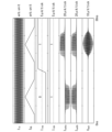
- FIG. 2 is a diagram showing an example of simulation results by the quantum bit control circuit 1 according to this embodiment.
- the value of each physical quantity is shown for 30 nanoseconds.
- the frequency of the first excitation current Ilo is 5 GHz as described above.
- the second excitation current Ibb is a triangular wave as described above.
- the values of the first excitation current Ilo and the second excitation current Ibb are expressed in arbitrary units.
- the input current Iina indicates a logic state of "0, 1" as an example. Depending on the logic state, the input current Iina changes value from low to high around 15 ns.
- the input current Iinb shows a logic state of "1, 1" as an example. Depending on the logic state, the input current Iinb is always high in value. Note that in FIG. 2, the units of the values of the input current Iina and the input current Iinb are 5 ⁇ A/tick.
- the output current Iouta is generated based on the first excitation current Ilo, the second excitation current Ibb, and the input current Iina.
- the output current Ioutb is generated based on the first excitation current Ilo, the second excitation current Ibb and the input current Iinb. Due to the magnetic flux applied by the first excitation current Ilo, which is the local oscillator signal, both the output current Iouta and the output current Ioutb oscillate at 5 GHz, the frequency of the first excitation current Ilo. Moreover, both the output current Iouta and the output current Ioutb are output based on the waveform of the second excitation current Ibb due to the magnetic flux applied by the second excitation current Ibb, which is the baseband signal.
- the waveform of the second excitation current Ibb defines the timing at which the output current Iouta and the output current Ioutb are output.
- the amplitude and duty ratio of each of the output currents Iouta and Ioutb are defined by the waveform of the second excitation current Ibb.
- the first power line 2 and the second power line 3, and the QFP gate 4a is excited and the output current Iouta is defined by the second excitation current Ibb generated. Since the output current Iouta is generated at the timing defined by the second excitation current Ibb, the amplitude and duty ratio of the output current Iouta gradually increase as the second excitation current Ibb rises, and the second excitation current Ibb It gradually decreases according to the fall of . Similarly, magnetic fluxes are applied to the QFP gate 4b from the first power line 2 and the second power line 3, respectively, to excite the QFP gate 4b and the output current Ioutb is defined by the second excitation current Ibb.
- the amplitude and duty ratio of the output current Ioutb gradually increase as the second excitation current Ibb rises, and the second excitation current Ibb It gradually decreases according to the fall of .
- the range in which the output current Iouta oscillates depends on the logical state indicated by the input current Iina. . That is, the logic value indicated by the output current Iouta is based on the logic value indicated by the input current Iina. When the input current Iina indicates a low, the output current Iouta oscillates in a range indicating a logic false value, and when the input current Iina indicates a high, the output current Iouta oscillates in a range indicating a true logic value.
- the range in which the output current Ioutb oscillates depends on the logical state indicated by the input current Iinb.
- the logic value indicated by the output current Ioutb is based on the logic value indicated by the input current Iinb.
- the input current Iinb always indicates high.
- the output current Ioutb oscillates in a range indicating the true logic value without changing with time in response to the input current Iinb always indicating high. Note that in FIG. 2, the unit of each value of the output current Iouta and the output current Ioutb is 20 ⁇ A/tick.
- the output microwave Vout is generated based on the output current Iouta and the output current Ioutb.
- the logic value indicated by the output current Iouta is based on the logic value indicated by the input current Iina
- the logic value indicated by the output current Ioutb is based on the logic value indicated by the input current Iinb.
- the output microwave Vout is output when the logical value indicated by the input current Iina matches the logical value indicated by the input current Iinb.
- the output microwave Vout is not output when the logical value indicated by the input current Iina and the logical value indicated by the input current Iinb do not match.
- whether or not the output microwave Vout is output is defined based on the logical value indicated by the output current Iouta. be done.
- the direction of oscillation is opposite to that of the output current Ioutb and the phases are aligned between the output current Iouta and the output current Ioutb.
- the amplitude of the output microwave Vout is zero.
- the direction and phase of oscillation are aligned between the output current Iouta and the output current Ioutb, and both the output current Iouta and the output current Ioutb are on the electromotive force output line.
- the waveform of the output microwave Vout becomes a waveform that oscillates at 5 GHz with the amplitude gradually increasing and then gradually decreasing.
- the unit of the value of the output microwave Vout is 10 ⁇ V/tick.
- the amplitudes of the output current Iouta, the output current Ioutb, and the output microwave Vout are compared.
- the amplitudes of the output currents Iouta and Ioutb tend to saturate.
- the amplitude of the output microwave Vout tends to continue increasing even after the amplitudes of the output currents Iouta and Ioutb start to saturate. This is because the duty ratio of the output signals (output current Iouta, output current Ioutb) generated by the QFP gates (QFP gate 4a, QFP gate 4b) changes during one cycle.
- the timing at which the output microwave Vout is output and the waveform (the envelope thereof) of the output microwave Vout are defined by the waveform of the second excitation current Ibb.
- the waveform of the output microwave Vout is a waveform obtained by mixing the waveform of the first excitation current Ilo and the waveform of the second excitation current Ibb. Therefore, the qubit control circuit 1 functions as a mixer. Further, it is possible to control whether or not the output microwave Vout is output according to the logical value indicated by the input current Iina and the logical value indicated by the input current Iinb.
- FIG. 3 is a diagram showing an example of the spectrum of the second excitation current Ibb, which is the baseband signal according to this embodiment.
- FIG. 4 is a diagram showing an example of the spectrum of the output microwave Vout according to this embodiment. 3 and 4 respectively show the amplitude values versus the frequency of the signal.
- the spectral maximum of the baseband signal shown in FIG. 3 is at 0 GHz, while the spectral maximum of the output microwave Vout shown in FIG. 4 is at 5 GHz. That is, it can be seen that the qubit control circuit 1 up-converts the second excitation current Ibb, which is the baseband signal, with the first excitation current Ilo, which is the local oscillator signal oscillating at 5 GHz.
- the qubit control circuit 1 since the second excitation current Ibb of the QFP and the output signals (output current Iouta, output current Ioutb) have a nonlinear relationship, the qubit control circuit 1 functions as a nonlinear mixer. . Further, the qubit control circuit 1 can control the waveform of the output microwave Vout based on the nonlinear relationship between the second excitation current Ibb and the output microwave Vout.
- a qubit control circuit may comprise only one QFP gate. That is, the quantum bit control circuit may be configured to include the first power line 2, the second power line 3, and the QFP gate (for example, the QFP gate 4a). Also, the qubit control circuit may comprise three or more QFP gates. That is, the quantum bit control circuit may have a configuration including the first power line 2, the second power line 3, and three or more QFP gates.
- the first power supply line 2 receives the first excitation current Ilo, which is a current with a predetermined frequency.
- a second excitation current Ibb which is a current having a predetermined waveform, is input to the second power supply line 3 .
- the output signal generation circuit 40a includes an input signal line (eg, an input signal line 5a) to which an input signal (eg, an input current Iina) indicating a logic state is input, and a magnetic coupling section (eg, an inductor L31a, an inductor L32a), and Josephson junctions (as examples, Josephson junction J1a and Josephson junction J2a).
- the Josephson junctions (for example, Josephson junction J1a and Josephson junction J2a) have the frequency of the first excitation current Ilo input via the magnetic coupling section (for example, inductor L31a and inductor L32a) and the second excitation current It outputs an output signal (eg, output current Iouta) corresponding to the waveform of Ibb and the logic state indicated by the input signal (eg, input current Iina).
- the quantum bit control circuit may be provided with one power line that serves both as the first power line 2 and the second power line 3 .
- the qubit control circuit is provided with one power line serving as both the first power line 2 and the second power line 3 .
- the one power line has the first excitation current Ilo and the second excitation current. Ibb and both excitation currents are input.
- a qubit control circuit including a first power supply line 2, a second power supply line 3, and an output signal generation circuit 40a outputs an output corresponding to the waveform of the first excitation current Ilo and the waveform of the second excitation current Ibb. Since the circuit to be obtained is configured by combining the magnetic coupling portion and the Josephson junction, it can be realized with a circuit configuration that suppresses heat generation. Since the quantum bit control circuit described above has a circuit configuration that suppresses heat generation, it can be arranged in a refrigerator.
- a qubit control circuit comprising the first power supply line 2, the second power supply line 3, and the output signal generation circuit 40a is an element constituting a qubit control circuit capable of controlling a large number of qubits with a small number of cables. It can be used as a circuit. A specific example of a qubit control circuit capable of controlling a large number of qubits with a small number of cables will be described in the second embodiment.
- the qubit control circuit 1 includes a plurality of superconducting gate circuits (QFP gates 4a and 4b in this embodiment), a fourth magnetic coupling section ( , an inductor L5a, an inductor L5b) and an output signal line (electromotive force output line 8 in this embodiment).
- a plurality of superconducting gate circuits each have an output signal generation circuit (in this embodiment, output signal generation circuit 40a and output signal generation circuit 40b) and an output signal (
- a third magnetic coupling section load inductor L4a, load inductor L4b in the present embodiment
- the fourth magnetic coupling section magnetically couples with the third magnetic coupling sections (load inductors L4a and L4b in this embodiment) of the plurality of superconducting gate circuits.
- the output signal line (in this embodiment, the electromotive force output line 8) is an output signal (in this embodiment, the output An electromagnetic wave (in this embodiment, the output microwave Vout ).
- the quantum bit control circuit 1 has a circuit configuration that suppresses heat generation, so it can be arranged inside the refrigerator.
- the qubit control circuit 1 can be used as a circuit that constitutes a qubit control circuit that can control a large number of qubits with a small number of cables.
- a specific example of a qubit control circuit capable of controlling a large number of qubits with a small number of cables will be described in the second embodiment.
- FIG. 5 is a diagram showing an example of the configuration of the quantum bit control circuit 1A according to this embodiment.
- the qubit control circuit 1A includes a first power line 2A, a second power line 3A, a resonant circuit 11A (resonant circuit 11A-1, resonant circuit 11A-2, resonant circuit 11A-3), and a QFP mixer 4A (QFP mixer 4A-1, QFP mixer 4A-2, and QFP mixer 4A-3).
- the quantum bit control circuit 1A includes a QFP mixer 4A and a resonance circuit 11A for each of multiple frequencies.
- the first power line 2A is a power line to which the first excitation current Ilo is input.
- the first excitation current Ilo is a current containing multiple frequencies. In other words, the first excitation current Ilo includes multiple frequencies.
- the plurality of frequencies included in the first excitation current Ilo are respectively frequencies corresponding to the qubits 12A-1, 12A-2, and 12A-3 to be controlled by the qubit control circuit 1A.
- the first excitation current Ilo includes, for example, three frequencies: frequency f1, frequency f2, and frequency f3.
- the first power line 2A includes an inductor L1-1, an inductor L1-2, and an inductor L1-3.
- the second power line 3A is a power line to which the second excitation current Ibb is input.
- the second excitation current Ibb is a current with a predetermined waveform.
- the second excitation current Ibb is a baseband signal supplied as an output signal from the baseband circuit.
- the waveform of the second excitation current Ibb flowing through the second power supply line 3A is, for example, a triangular wave like the waveform of the second excitation current Ibb flowing through the second power supply line 3 shown in FIG.
- the second power line 3A includes an inductor L4-1, an inductor L4-2, and an inductor L4-3.
- the resonant circuit 11A-1, resonant circuit 11A-2, and resonant circuit 11A-3 each extract a specific frequency from multiple frequencies contained in the first excitation current Ilo by resonance.
- the resonance circuits 11A-1, 11A-2, and 11A-3 have the same function except that they have different resonance frequencies. Therefore, the resonance circuit 11A-1 will be described below, and the description of the resonance circuits 11A-2 and 11A-3 will be omitted.
- the resonance circuit 11A-1 is a circuit that resonates at a predetermined frequency (resonance frequency).
- the resonance frequency is equal to one of the frequencies included in the first excitation current Ilo.
- the resonant circuit 11A-1 is, for example, an LC circuit.
- the resonance circuit 11A-1 includes an inductor L2-1 and an inductor L3-1.
- Inductor L2-1 is magnetically coupled with inductor L1-1 provided in first power supply line 2A.
- Inductor L3-1 is magnetically coupled with inductor L5-1 provided in QFP mixer 4A-1.
- QFP mixer 4A (QFP mixer 4A-1, QFP mixer 4A-2, QFP mixer 4A-3) mixes first excitation current Ilo as a local oscillator signal and second excitation current Ibb as a baseband signal. It is a QFP circuit for The QFP mixer 4A-1, the QFP mixer 4A-2, and the QFP mixer 4A-3 have similar functions except that the frequencies included in the first excitation current Ilo mixed with the second excitation current Ibb are different. Therefore, the QFP mixer 4A-1 will be explained below, and the explanation of the QFP mixers 4A-2 and 4A-3 will be omitted.
- the QFP mixer 4A-1 is a mixer having the same configuration as the quantum bit control circuit 1 shown in FIG. In FIG. 5, the magnetic coupling between the QFP mixer 4A-1 and other circuit elements is abstracted by the inductor L5-1.
- the resonance circuit 11A-1 when the first excitation current Ilo flows through the first power supply line 2A, the magnetic coupling between the inductor L2-1 and the inductor L1-1 causes a plurality of currents included in the first excitation current Ilo to flow. A current of a frequency that resonates itself among the frequencies flows. Therefore, the resonance circuit 11A-1 extracts the same frequency as its own resonance frequency from among a plurality of frequencies contained in the first excitation current Ilo flowing through the first power supply line 2A.
- the resonance circuit 11A-1 and the first power supply line 2A are coupled by magnetic coupling via the inductor L2-1 and the inductor L1-1 will be described, but the present invention is not limited to this. .
- the coupling between the resonance circuit 11A-1 and the first power supply line 2A may be capacitive coupling via a capacitor.
- the current having the resonant frequency flowing through the resonant circuit 11A-1 is referred to as component excitation current Ir1.
- the component excitation current Ir1 flows through the resonance circuit 11A-1 and the second excitation current Ibb flows through the second power supply line 3A. 1 and magnetic coupling between the inductor L5-1 and the inductor L4-1 provided in the second power supply line 3A, the input current Iin1 is a current that is input to an input signal line (not shown). outputs an output signal corresponding to
- FIG. 5 the fact that the second power supply line 3A and the QFP mixer 4A-1 are magnetically coupled is represented by an inductor L5-1 and an inductor L4-1. Magnetic coupling with the QFP mixer 4A-1 is represented by inductors L5-1 and L3-1.
- FIG. 5 the configuration corresponding to inductors L31a, L32a, L31b, and L32b shown in FIG. 1 is abstracted by inductor L5-1.
- the output signal output from the QFP mixer 4A-1 is the output microwave Vout1, which is a microwave.
- the frequency of the output microwave Vout1 is the same as the frequency f1 extracted by the resonant circuit 11A-1 from the frequency-multiplexed first excitation current Ilo. That is, the QFP mixer 4A-1 outputs, as an output signal, the microwave of frequency f1 extracted from the first excitation current Ilo by the resonance circuit 11A-1.
- the input current Iin1 is supplied from a circuit provided separately from the qubit control circuit 1A.
- the output microwave Vout1 of frequency f1 output by the QFP mixer 4A-1 is irradiated to the quantum bit 12A-1.
- the output microwave Vout2 of frequency f2 output by the QFP mixer 4A-2 is applied to the quantum bit 12A-2.
- the output microwave Vout3 of frequency f3 output by the QFP mixer 4A-3 is applied to the quantum bit 12A-3.
- ON and OFF of the output microwave Vout1, the output microwave Vout2, and the output microwave Vout3 are controlled by the logic states indicated by the input currents Iin1, Iin2, and Iin3, respectively.
- the amplitude of the output microwave of the output microwave Vout1, the output microwave Vout2, or the output microwave Vout3 is controlled by adjusting the amplitude of each frequency component included in the first excitation current Ilo. be able to. That is, in the qubit control circuit 1A, the amplitude of the output microwave can be controlled by the spectrum of the first excitation current Ilo.
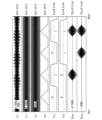
- FIG. 6 is a diagram showing an example of simulation results by the quantum bit control circuit 1A according to this embodiment.
- the simulation results shown in FIG. 6 are results for the case where the first excitation current Ilo contains two frequencies.
- the value of each physical quantity is shown for 65 nanoseconds.
- the first excitation current Ilo includes two frequencies of 4.5 GHz and 5 GHz.
- the frequency of the component excitation current Ir1 that flows through resonance in the resonance circuit 11A-1 is 4.5 GHz.
- the frequency of the component excitation current Ir2 that flows through resonance in the resonance circuit 11A-2 is 5 GHz.
- the second excitation current Ibb is a triangular wave.
- the values of the first excitation current Ilo, the component excitation current Ir1, the component excitation current Ir2, and the second excitation current Ibb are expressed in arbitrary units.
- An input current Iin1 input to the QFP mixer 4A-1 indicates a logic state of "0, 1, 0, 1" as an example.
- An input current Iin2 input to the QFP mixer 4A-2 exhibits logic states of "0, 0, 1, 1" as an example.
- the unit of each value of the input current Iin1 and the input current Iin2 is 5 ⁇ A/tick.
- the output microwave Vout1 is generated based on the frequency of 4.5 GHz included in the first excitation current Ilo, the second excitation current Ibb, and the input current Iin1.
- the output microwave Vout1 becomes the logic indicated by the input current Iin1. It oscillates at 4.5 GHz with an amplitude that depends on the state.
- the output microwave Vout1 has an amplitude of almost zero and does not oscillate during the period when the logic state indicated by the input current Iin1 is "0", and during the period when the logic state is "1", the second excitation current Ibb is non-linearly reflected and oscillates at 4.5 GHz.
- FIG. 6 shows the simulation results when the logic value of the other input signal is "1". Since the logic state of the other input signal is fixed at "1”, when the logic value of the input current Iin1 is "1", the output microwave Vout1 is output with a predetermined amplitude, and the input When the logic value of the current Iin1 is "0", the output microwave Vout1 has almost zero amplitude and is not output. The same applies to the relationship between the input current Iin2 and the output microwave Vout2.
- the output microwave Vout2 is generated based on the frequency of 5 GHz contained in the first excitation current Ilo, the second excitation current Ibb, and the input current Iin2.
- the output microwave Vout2 is brought to the logic state indicated by the input current Iin2. It oscillates at 5 GHz with a corresponding amplitude.
- the output microwave Vout2 has an amplitude of almost zero and does not oscillate during the period when the logic state indicated by the input current Iin2 is "0", and during the period when the logic state is "1", the second excitation current Ibb is non-linearly reflected and oscillates at 5 GHz.
- the unit of each value of the output microwave Vout1 and the output microwave Vout2 is 10 ⁇ V/tick.
- FIG. 7 is a diagram showing an example of the relationship between the spectrum of the first excitation current Ilo and the amplitude of the output microwave according to this embodiment.
- the amplitude of the 5 GHz frequency component is reduced in the first excitation current Ilo shown in FIG. 7 compared to the first excitation current Ilo shown in FIG.
- the power of the 5 GHz frequency component is ⁇ 55.7 dBm for the first excitation current Ilo shown in FIG. 6, whereas it is ⁇ 58.7 dBm for the first excitation current Ilo shown in FIG.
- the amplitude of the 4.5 GHz frequency component is -56.6 dBm for both the first excitation current Ilo shown in FIG. 6 and the first excitation current Ilo shown in FIG.
- the amplitude and pulse width of the output microwave Vout2 are reduced.
- the output microwave Vout1 is not changed in amplitude and pulse width.
- the electromagnetic waves output by the output signal line (not shown in this embodiment and corresponding to the electromotive force output line 8 in FIG. 1) (in this embodiment, the output microwave Vout1, the output microwave Vout2, the output microwave The amplitude and pulse width of Vout3) are controlled by the amplitude of the predetermined frequency component of the first excitation current Ilo. Note that even if only one configuration corresponding to the QFP mixer 4A is provided as in the quantum bit control circuit 1 (FIG. 1) according to the first embodiment described above, the first excitation current Ilo By changing the amplitude, the amplitude and pulse width of the output microwave Vout can be adjusted.
- the first excitation current Ilo input to the first power supply line 2A has a plurality of frequencies (frequency f1, f2 , and frequency f3), and an output signal generation circuit (not shown in this embodiment, an output signal generation circuit 40a in the configuration of the QFP gate 4a in FIG. 1, and an output signal generation circuit 40a in the configuration of the QFP gate 4b in FIG. generating circuit 40b) and a resonance circuit for each of a plurality of frequencies (frequency f1, frequency f2, and frequency f3 in this embodiment).
- the resonant circuit (resonant circuit 11A-1, resonant circuit 11A-2, and resonant circuit 11A-3 in this embodiment) includes a coupling portion (in this embodiment, inductor L2-1, inductor L2-2, inductor L2-3), an output signal generation circuit (not shown in the present embodiment, an output signal generation circuit 40a in the configuration of the QFP gate 4a in FIG. 1, and an output signal generation circuit 40a in the configuration of the QFP gate 4b in FIG.
- a coupling portion in this embodiment, inductor L2-1, inductor L2-2, inductor L2-3
- an output signal generation circuit (not shown in the present embodiment, an output signal generation circuit 40a in the configuration of the QFP gate 4a in FIG. 1, and an output signal generation circuit 40a in the configuration of the QFP gate 4b in FIG.
- the corresponding output signal is generated by flowing a current of the resonance frequency through the second magnetic coupling unit (inductor L3-1, inductor L3-2, and inductor L3-3 in this embodiment).
- a generation circuit (not shown in the present embodiment, corresponding to the output signal generation circuit 40a in the configuration of the QFP gate 4a in FIG. 1 and the output signal generation circuit 40b in the configuration of the QFP gate 4b) is supplied with the resonance frequency as the first frequency. Supplied as the frequency of 1 power line 2A.
- the number of cables required for controlling the qubits is two, the first power supply line 2A and the second power supply line 3A, regardless of the number of qubits. Because it is a book, a small number of cables can control a large number of qubits. Here, a small number of cables means a small number compared to the number of quantum bits to be controlled.
- the frequencies contained in the first excitation current Ilo may be one, two, four or more depending on the number of qubits to be controlled.
- the qubit control circuit includes at least a set of resonant circuits and output signal generating circuits, the number of which is equal to or greater than the number of frequencies included in the first excitation current Ilo. Some sets of resonant circuits and output signal generating circuits included in the qubit control circuit may not be used. Moreover, a plurality of sets of the resonance circuit and the output signal generation circuit may correspond to one frequency included in the first excitation current Ilo.
- the resonance circuit and the power supply line (first power supply line) are magnetically coupled
- the present invention is not limited to this.
- the resonant circuit and the power line may be coupled by capacitive coupling.
- the QFP provided in the qubit control circuit in each of the above-described embodiments may be an adiabatic flux quantum parametron (AQFP) or a directly coupled flux quantum parametron (DQFP).
- AQFP adiabatic flux quantum parametron
- DQFP directly coupled flux quantum parametron
- the electromagnetic waves generated by the quantum bit control circuits 1 and 1A and applied to the controlled object (qubit) are microwaves, but the present invention is not limited to this.
- the frequency of the electromagnetic wave generated by the quantum bit control circuits 1 and 1A and irradiated to the controlled object (qubit) may be other than the microwave frequency.
- the quantum bit control circuits 1 and 1A may generate electromagnetic waves with frequencies other than microwave frequencies and irradiate the control target with them.
- control target of the quantum bit control circuit is a quantum bit
- the invention is not limited to this.
- a control object other than the quantum bit may be controlled by a circuit having the same configuration as the quantum bit control circuit according to each of the embodiments described above.
- Control objects other than quantum bits are, for example, various components that make up a circuit of a quantum computer.
Landscapes
- Engineering & Computer Science (AREA)
- Physics & Mathematics (AREA)
- General Physics & Mathematics (AREA)
- Theoretical Computer Science (AREA)
- Mathematical Physics (AREA)
- General Engineering & Computer Science (AREA)
- Computing Systems (AREA)
- Condensed Matter Physics & Semiconductors (AREA)
- Mathematical Analysis (AREA)
- Mathematical Optimization (AREA)
- Pure & Applied Mathematics (AREA)
- Evolutionary Computation (AREA)
- Data Mining & Analysis (AREA)
- Computational Mathematics (AREA)
- Software Systems (AREA)
- Artificial Intelligence (AREA)
- Computer Hardware Design (AREA)
- Superconductor Devices And Manufacturing Methods Thereof (AREA)
Priority Applications (1)
| Application Number | Priority Date | Filing Date | Title |
|---|---|---|---|
| JP2024504673A JPWO2023167129A1 (https=) | 2022-03-03 | 2023-02-27 |
Applications Claiming Priority (2)
| Application Number | Priority Date | Filing Date | Title |
|---|---|---|---|
| JP2022032905 | 2022-03-03 | ||
| JP2022-032905 | 2022-03-03 |
Publications (1)
| Publication Number | Publication Date |
|---|---|
| WO2023167129A1 true WO2023167129A1 (ja) | 2023-09-07 |
Family
ID=87883614
Family Applications (1)
| Application Number | Title | Priority Date | Filing Date |
|---|---|---|---|
| PCT/JP2023/007010 Ceased WO2023167129A1 (ja) | 2022-03-03 | 2023-02-27 | 量子ビット制御回路 |
Country Status (2)
| Country | Link |
|---|---|
| JP (1) | JPWO2023167129A1 (https=) |
| WO (1) | WO2023167129A1 (https=) |
Citations (4)
| Publication number | Priority date | Publication date | Assignee | Title |
|---|---|---|---|---|
| JPS59143427A (ja) * | 1983-02-04 | 1984-08-17 | Rikagaku Kenkyusho | 超伝導磁束量子論理演算回路 |
| JPS6089126A (ja) * | 1983-10-21 | 1985-05-20 | Agency Of Ind Science & Technol | 超電導論理回路 |
| US5396242A (en) * | 1992-08-26 | 1995-03-07 | Lee; Gregory S. | Superconductivity binary odometer |
| JP2021518991A (ja) * | 2018-06-26 | 2021-08-05 | ノースロップ グラマン システムズ コーポレーション | 磁束源システム |
-
2023
- 2023-02-27 JP JP2024504673A patent/JPWO2023167129A1/ja active Pending
- 2023-02-27 WO PCT/JP2023/007010 patent/WO2023167129A1/ja not_active Ceased
Patent Citations (4)
| Publication number | Priority date | Publication date | Assignee | Title |
|---|---|---|---|---|
| JPS59143427A (ja) * | 1983-02-04 | 1984-08-17 | Rikagaku Kenkyusho | 超伝導磁束量子論理演算回路 |
| JPS6089126A (ja) * | 1983-10-21 | 1985-05-20 | Agency Of Ind Science & Technol | 超電導論理回路 |
| US5396242A (en) * | 1992-08-26 | 1995-03-07 | Lee; Gregory S. | Superconductivity binary odometer |
| JP2021518991A (ja) * | 2018-06-26 | 2021-08-05 | ノースロップ グラマン システムズ コーポレーション | 磁束源システム |
Also Published As
| Publication number | Publication date |
|---|---|
| JPWO2023167129A1 (https=) | 2023-09-07 |
Similar Documents
| Publication | Publication Date | Title |
|---|---|---|
| CA2968847C (en) | Josephson current source systems and method | |
| CA2925868C (en) | Josephson ac/dc converter systems and method | |
| JP3560997B2 (ja) | マイクロプロセッサ回路 | |
| US9467126B1 (en) | Josephson current source systems and method | |
| JP6556952B2 (ja) | ジョセフソン伝送路(jtl)システム | |
| TWI759415B (zh) | 脈衝產生器 | |
| CN101889253B (zh) | 集成电路时钟管理技术 | |
| JPH09266444A (ja) | 組合せロジックを利用した電圧制御発振器を有するフェーズロックループ | |
| EP4106192A1 (en) | Superconducting current source system | |
| JP4733085B2 (ja) | 素子状態読み出し装置、方法、および透過型ジョセフソン共振回路 | |
| KR20210101318A (ko) | 조셉슨 전류원 시스템 | |
| WO2023167129A1 (ja) | 量子ビット制御回路 | |
| CN113972902B (zh) | 时钟信号产生电路、时钟信号产生方法及电子设备 | |
| WO2023167070A1 (ja) | 量子ビット制御回路 | |
| CN102237859A (zh) | 由电流源相对大小决定频率的振荡器 | |
| CN107077163B (zh) | 时钟相位对齐 | |
| CN211127756U (zh) | Pwm信号的生成电路、芯片 | |
| Kuttappa et al. | Low frequency rotary traveling wave oscillators | |
| Kebapcıoğlu et al. | A power-efficient magnetic actuator driver design | |
| Cheng | Implementation of high resolution digital pulse width modulator based on FPGA | |
| Kuttappa et al. | Low Swing—Low Frequency Rotary Traveling Wave Oscillators | |
| JP2014158114A (ja) | クロック発生デバイス | |
| Marconi et al. | A novel HDL coding style to reduce power consumption for reconfigurable devices | |
| KR100502932B1 (ko) | 주파수 변환 장치 및 이를 이용한 플라즈마 디스플레이패널의 구동 장치 | |
| Ghodke et al. | New multiplexed all solid state pulser for high power wide aperture kinetically enhanced copper vapor laser |
Legal Events
| Date | Code | Title | Description |
|---|---|---|---|
| 121 | Ep: the epo has been informed by wipo that ep was designated in this application |
Ref document number: 23763387 Country of ref document: EP Kind code of ref document: A1 |
|
| ENP | Entry into the national phase |
Ref document number: 2024504673 Country of ref document: JP Kind code of ref document: A |
|
| NENP | Non-entry into the national phase |
Ref country code: DE |
|
| 122 | Ep: pct application non-entry in european phase |
Ref document number: 23763387 Country of ref document: EP Kind code of ref document: A1 |