WO2023166787A1 - Sensor-equipped seat - Google Patents
Sensor-equipped seat Download PDFInfo
- Publication number
- WO2023166787A1 WO2023166787A1 PCT/JP2022/040439 JP2022040439W WO2023166787A1 WO 2023166787 A1 WO2023166787 A1 WO 2023166787A1 JP 2022040439 W JP2022040439 W JP 2022040439W WO 2023166787 A1 WO2023166787 A1 WO 2023166787A1
- Authority
- WO
- WIPO (PCT)
- Prior art keywords
- sensor
- cushion
- seat
- seat cushion
- sheet
- Prior art date
Links
- 230000004308 accommodation Effects 0.000 claims abstract description 57
- 238000007906 compression Methods 0.000 claims abstract description 13
- 238000006243 chemical reaction Methods 0.000 claims abstract description 5
- 238000001514 detection method Methods 0.000 claims description 70
- 238000009423 ventilation Methods 0.000 claims description 59
- 239000000463 material Substances 0.000 claims description 44
- 239000012212 insulator Substances 0.000 claims description 30
- 230000006835 compression Effects 0.000 claims description 11
- 230000000149 penetrating effect Effects 0.000 claims description 3
- 238000000034 method Methods 0.000 claims description 2
- 238000003475 lamination Methods 0.000 abstract description 4
- 230000035945 sensitivity Effects 0.000 description 15
- 210000001217 buttock Anatomy 0.000 description 12
- 229920005989 resin Polymers 0.000 description 12
- 239000011347 resin Substances 0.000 description 12
- 239000002184 metal Substances 0.000 description 8
- 229920001971 elastomer Polymers 0.000 description 7
- 239000000806 elastomer Substances 0.000 description 7
- 230000010349 pulsation Effects 0.000 description 7
- 230000029058 respiratory gaseous exchange Effects 0.000 description 7
- 230000000694 effects Effects 0.000 description 5
- 239000011148 porous material Substances 0.000 description 5
- PPBRXRYQALVLMV-UHFFFAOYSA-N Styrene Chemical compound C=CC1=CC=CC=C1 PPBRXRYQALVLMV-UHFFFAOYSA-N 0.000 description 4
- 239000013013 elastic material Substances 0.000 description 4
- 239000004744 fabric Substances 0.000 description 4
- 229920002647 polyamide Polymers 0.000 description 4
- 239000000725 suspension Substances 0.000 description 4
- 239000004952 Polyamide Substances 0.000 description 3
- 239000000945 filler Substances 0.000 description 3
- 239000012528 membrane Substances 0.000 description 3
- 230000002093 peripheral effect Effects 0.000 description 3
- JOYRKODLDBILNP-UHFFFAOYSA-N Ethyl urethane Chemical compound CCOC(N)=O JOYRKODLDBILNP-UHFFFAOYSA-N 0.000 description 2
- NIXOWILDQLNWCW-UHFFFAOYSA-N acrylic acid group Chemical group C(C=C)(=O)O NIXOWILDQLNWCW-UHFFFAOYSA-N 0.000 description 2
- 150000001336 alkenes Chemical class 0.000 description 2
- 230000002238 attenuated effect Effects 0.000 description 2
- 150000002148 esters Chemical class 0.000 description 2
- 239000011888 foil Substances 0.000 description 2
- 239000010985 leather Substances 0.000 description 2
- JRZJOMJEPLMPRA-UHFFFAOYSA-N olefin Natural products CCCCCCCC=C JRZJOMJEPLMPRA-UHFFFAOYSA-N 0.000 description 2
- 229920000098 polyolefin Polymers 0.000 description 2
- 229920003002 synthetic resin Polymers 0.000 description 2
- 239000000057 synthetic resin Substances 0.000 description 2
- 210000000689 upper leg Anatomy 0.000 description 2
- 230000005540 biological transmission Effects 0.000 description 1
- 239000000470 constituent Substances 0.000 description 1
- 230000003247 decreasing effect Effects 0.000 description 1
- 230000002542 deteriorative effect Effects 0.000 description 1
- 238000006073 displacement reaction Methods 0.000 description 1
- 230000005489 elastic deformation Effects 0.000 description 1
- 239000006261 foam material Substances 0.000 description 1
- 238000005187 foaming Methods 0.000 description 1
- 230000004927 fusion Effects 0.000 description 1
- 238000009413 insulation Methods 0.000 description 1
- 239000011159 matrix material Substances 0.000 description 1
- -1 or the like Substances 0.000 description 1
Images


Classifications
-
- B—PERFORMING OPERATIONS; TRANSPORTING
- B60—VEHICLES IN GENERAL
- B60N—SEATS SPECIALLY ADAPTED FOR VEHICLES; VEHICLE PASSENGER ACCOMMODATION NOT OTHERWISE PROVIDED FOR
- B60N2/00—Seats specially adapted for vehicles; Arrangement or mounting of seats in vehicles
- B60N2/002—Seats provided with an occupancy detection means mounted therein or thereon
-
- A—HUMAN NECESSITIES
- A47—FURNITURE; DOMESTIC ARTICLES OR APPLIANCES; COFFEE MILLS; SPICE MILLS; SUCTION CLEANERS IN GENERAL
- A47C—CHAIRS; SOFAS; BEDS
- A47C7/00—Parts, details, or accessories of chairs or stools
- A47C7/62—Accessories for chairs
-
- A—HUMAN NECESSITIES
- A61—MEDICAL OR VETERINARY SCIENCE; HYGIENE
- A61B—DIAGNOSIS; SURGERY; IDENTIFICATION
- A61B5/00—Measuring for diagnostic purposes; Identification of persons
- A61B5/103—Detecting, measuring or recording devices for testing the shape, pattern, colour, size or movement of the body or parts thereof, for diagnostic purposes
- A61B5/11—Measuring movement of the entire body or parts thereof, e.g. head or hand tremor, mobility of a limb
- A61B5/113—Measuring movement of the entire body or parts thereof, e.g. head or hand tremor, mobility of a limb occurring during breathing
-
- B—PERFORMING OPERATIONS; TRANSPORTING
- B60—VEHICLES IN GENERAL
- B60N—SEATS SPECIALLY ADAPTED FOR VEHICLES; VEHICLE PASSENGER ACCOMMODATION NOT OTHERWISE PROVIDED FOR
- B60N2/00—Seats specially adapted for vehicles; Arrangement or mounting of seats in vehicles
- B60N2/56—Heating or ventilating devices
-
- B—PERFORMING OPERATIONS; TRANSPORTING
- B60—VEHICLES IN GENERAL
- B60N—SEATS SPECIALLY ADAPTED FOR VEHICLES; VEHICLE PASSENGER ACCOMMODATION NOT OTHERWISE PROVIDED FOR
- B60N2/00—Seats specially adapted for vehicles; Arrangement or mounting of seats in vehicles
- B60N2/70—Upholstery springs ; Upholstery
- B60N2/7094—Upholstery springs
-
- B—PERFORMING OPERATIONS; TRANSPORTING
- B60—VEHICLES IN GENERAL
- B60N—SEATS SPECIALLY ADAPTED FOR VEHICLES; VEHICLE PASSENGER ACCOMMODATION NOT OTHERWISE PROVIDED FOR
- B60N2/00—Seats specially adapted for vehicles; Arrangement or mounting of seats in vehicles
- B60N2/90—Details or parts not otherwise provided for
Definitions
- FIG. 2 and 3 show the sensor 3 alone, that is, the sensor 3 before assembly to the seat body 2.
- the concave groove 82c is formed along the periphery of the convex portion 82a. That is, the concave groove 82c constitutes a boundary portion between the inner side surface of the accommodation concave portion 80 and the convex portion 82a, and is formed along the entire periphery of the convex portion 82a.
- the thickness dimension of the second seat cushion 15 and the thickness of the sensor 3 The sum b with the dimension is set larger than the depth dimension a from the anti-pressure receiving surface 12b of the housing recess 80 to the tip of the projection 82a.
- the thickness dimension of the second seat cushion 15 and the thickness dimension of the sensor 3 are different.
- the sum is the same as the depth dimension a from the anti-pressure receiving surface 12b of the first seat cushion to the first pressing surface 82b of the projection 82a. 31 precompressed.
- a ⁇ b It is said that in other words, in the stacking direction of the first seat cushion 112 and the second seat cushion 15, the sum b of the thickness dimension of the second seat cushion 15 and the thickness dimension of the sensor 3 is It is set larger than the depth dimension a from the anti-pressure receiving surface 12b of the recess 180 to the first pressing surface 182b.
- FIG. 3 differs from that of the second embodiment in that an elastic layer 90 capable of elastic deformation is provided between the first seat cushion 112 and the sensor 3 .
- a ⁇ b It is said that in other words, with respect to the stacking direction of the first seat cushion 112 and the second seat cushion 15, the thickness dimension of the second seat cushion 15, the thickness dimension of the sensor 3, and the thickness of the elastic layer 90 The sum b of the depth dimensions is set larger than the depth dimension a from the anti-pressure receiving surface 12b of the housing recess 180 to the first pressing surface 182b.
- the detection area 404 of this embodiment is formed in a rectangular shape when viewed from above.
- the shape of the detection area 404 is not limited to a square shape, and any shape such as a polygonal shape such as a triangle or a pentagon can be appropriately selected.
- the four detection areas 404 are spaced apart from each other at the four corners of the rectangular sensor 403 .
- the configuration of the detection area 404 is not limited to the configuration described above, and any configuration can be selected as appropriate.
- FIG. 19 As shown in FIG. 19, on the upper surface of the seat upholstery member 413, two side hanging grooves 471a extending in the front-rear direction are formed in portions near both sides in the left-right direction.
- the side hanging groove 471a is formed extending from the rear end to the front end of the seat surface upholstery member 413 .
- the end of the seat upholstery member 413 is folded toward the first seat cushion 412 in the side hanging groove 471a.
- the end of the seat upholstery member 413 is inserted from above into the first hanging through-hole 461b.
Landscapes
- Engineering & Computer Science (AREA)
- Health & Medical Sciences (AREA)
- Aviation & Aerospace Engineering (AREA)
- Transportation (AREA)
- Mechanical Engineering (AREA)
- Life Sciences & Earth Sciences (AREA)
- Biophysics (AREA)
- Molecular Biology (AREA)
- Physics & Mathematics (AREA)
- Dentistry (AREA)
- Physiology (AREA)
- Pathology (AREA)
- Biomedical Technology (AREA)
- Heart & Thoracic Surgery (AREA)
- Medical Informatics (AREA)
- Oral & Maxillofacial Surgery (AREA)
- Surgery (AREA)
- Animal Behavior & Ethology (AREA)
- General Health & Medical Sciences (AREA)
- Public Health (AREA)
- Veterinary Medicine (AREA)
- Chair Legs, Seat Parts, And Backrests (AREA)
- Seats For Vehicles (AREA)
Abstract
A sensor-equipped seat (1) is provided with a seating-surface seat cushion (10) that comprises: a first seating-surface seat cushion (12) having an accommodation recess (80); and a second seating-surface seat cushion (15) which is accommodated within the accommodation recess (80). Disposed between a first pressing surface (82b) of the accommodation recess (80) in the first seating-surface seat cushion (12) and a second pressing surface (15a) of the second seating-surface seat cushion (15) is a flexible sensor (3) that detects seating condition of a seated person or biological information of the seated person. The first seating-surface seat cushion (12) and the second seating-surface seat cushion (15) are pre-compressed in the lamination direction. Pre-compression is applied to the sensor (3) by compressive reactions of the first seating-surface seat cushion (12) and the second seating-surface seat cushion (15).
Description
本開示は、センサ付きシートに関する。
The present disclosure relates to a seat with sensors.
特許文献1には、シートにセンサを配置し、着座者の着座状態(着座姿勢など)や着座者の生体情報(呼吸、脈動、心拍など)を取得する構成が記載されている。特許文献1においては、センサは、シートフレームに取り付けられた状態で、シートフレームとシートクッションとの間に挟まれて配置されている。このセンサは、例えば、電磁波を水平方向に対する所定の照射角度で上方(着座している着座者)に向けて照射し、この反射波を受信して検波することで、着座者の脈動や呼吸に伴って発生する体表面変位を検出するようになっている。
Patent Document 1 describes a configuration for arranging a sensor on a seat to obtain the seating state of a seated person (seating posture, etc.) and the biological information of the seated person (breathing, pulsation, heartbeat, etc.). In Patent Literature 1, the sensor is sandwiched between the seat frame and the seat cushion while attached to the seat frame. For example, this sensor emits an electromagnetic wave upward (to the seated person) at a predetermined irradiation angle with respect to the horizontal direction, and receives and detects this reflected wave to detect the pulsation and breathing of the seated person. The accompanying body surface displacement is detected.
例えば、センサとして、着座者がシートに着座した際にシートに加わる圧力を検知する感圧センサを用いることが考えられる。
For example, it is conceivable to use a pressure sensor that detects the pressure applied to the seat when the occupant sits on the seat.
しかしながら、感圧センサをシートフレームに配置した場合、着座者の臀部とセンサとの距離が離れてしまうので、着座者の生体信号の強度が小さくなるという課題がある。
However, when the pressure sensor is placed on the seat frame, the distance between the buttocks of the seated person and the sensor increases, so there is a problem that the strength of the biosignal of the seated person is reduced.
また、センサをフレームに配置した場合、車両からの振動ノイズが、フレームからセンサに直接伝達されてしまうという課題がある。
Also, when the sensor is placed on the frame, there is the problem that vibration noise from the vehicle is directly transmitted from the frame to the sensor.
本開示は、かかる背景に鑑みてなされたものであり、検出される生体信号の強度が向上するとともに、ノイズが低減されたセンサ付きシートを提供しようとするものである。
The present disclosure has been made in view of such a background, and aims to provide a sensor-equipped sheet in which the strength of detected biosignals is improved and noise is reduced.
本開示の一態様は、
取り付け座面を有する取り付け部材と、
前記取り付け部材の前記取り付け座面に取り付けられるシートクッションであって、着座者から圧力をうける受圧面の裏側に位置する反受圧面において前記取り付け部材側に開口する収容凹部を有する第一クッションと、前記第一クッションの前記収容凹部内に収容されて前記第一クッションに積層される第二クッションと、を有する前記シートクッションと、
前記第一クッションの前記収容凹部のうち前記収容凹部の開口する方向と反対側に位置する第一押圧面と、前記第二クッションのうち前記取り付け部材と反対側に位置する第二押圧面と、の間に配置され、前記着座者による着座状態において前記シートクッションの前記受圧面から前記第一クッションを介して伝達される圧力に応じた物理量を検出することによって前記着座者の着座状態または前記着座者の生体情報を検出するとともに、可撓性を有するセンサと、を備え、
前記シートクッションが前記取り付け部材の前記取り付け座面に取り付けられ、且つ、前記着座者が前記シートクッションに着座する前の未着座状態において、前記第一クッションと前記第二クッションは、前記第一クッションと前記第二クッションが積層された積層方向に予圧縮されており、前記センサは、前記第一クッションと前記第二クッションの圧縮反力により予圧縮が付与されている、センサ付きシートにある。 One aspect of the present disclosure is
a mounting member having a mounting seating surface;
a seat cushion attached to the mounting seat surface of the mounting member, the first cushion having a housing recess opening toward the mounting member on a pressure-receiving surface located behind a pressure-receiving surface that receives pressure from a seated person; a second cushion that is accommodated in the accommodation recess of the first cushion and stacked on the first cushion;
a first pressing surface of the housing recess of the first cushion located on the side opposite to the direction in which the housing recess opens; a second pressing surface of the second cushion located on the side opposite to the mounting member; The seated state of the seated person or the seated state by detecting a physical quantity corresponding to the pressure transmitted from the pressure receiving surface of the seat cushion through the first cushion in the seated state of the seated person A sensor that detects the biological information of a person and has flexibility,
When the seat cushion is attached to the attachment seat surface of the attachment member and the seated person is not seated on the seat cushion before the seat cushion is seated, the first cushion and the second cushion and the second cushion are precompressed in the stacking direction, and the sensor is a seat with a sensor precompressed by a compression reaction force of the first cushion and the second cushion.
センサは第一クッションに設けられた収容凹部内に収容されているので、取り付け部材に取り付けられている場合に比べて、第一クッションの受圧面に近い位置に配されている。これにより、着座者から発せられた生体信号が第一クッションによって減衰することが抑制されるので、センサが受ける生体信号の強度を向上させることができる。
Since the sensor is accommodated in the accommodation recess provided in the first cushion, it is arranged at a position closer to the pressure receiving surface of the first cushion than when it is attached to the mounting member. As a result, attenuation of the biological signal emitted from the seated person by the first cushion is suppressed, so that the strength of the biological signal received by the sensor can be improved.
また、センサと、取り付け部材との間には、第二クッションが介在しているので、車両からの振動ノイズを、第二クッションによって減衰させることができる。
Also, since the second cushion is interposed between the sensor and the mounting member, vibration noise from the vehicle can be attenuated by the second cushion.
センサは可撓性を有するので、着座者がシートクッションに着座したことによってシートクッションが変形したとき、センサもシートクッションの変形に追従して変形する。これにより、着座者からの圧力と異なるノイズの発生を抑制することができる。
Since the sensor is flexible, when the seat cushion is deformed by the seated person sitting on it, the sensor is also deformed following the deformation of the seat cushion. As a result, it is possible to suppress the generation of noise that is different from the pressure from the seated person.
また、センサには、第一クッションおよび第二クッションの圧縮反力による予圧縮が付与されているので、着座者がシートクッションに着座した際に、着座者からシートクッションに付与される力が小さいとしても、この力はセンサに伝達されることが可能となる。この結果、センサの感度を向上させることができる。
In addition, since the sensor is precompressed by the compression reaction force of the first cushion and the second cushion, the force applied to the seat cushion by the occupant when the occupant is seated on the seat cushion is small. Even if , this force can be transmitted to the sensor. As a result, the sensitivity of the sensor can be improved.
以上より、センサ付きシートにおいて、検出される生体信号の強度が向上するとともに、ノイズが低減される。
As described above, in the sensor-equipped seat, the strength of the biosignal detected is improved and noise is reduced.
なお、請求の範囲に記載した括弧内の符号は、後述する実施形態に記載の具体的手段との対応関係を示すものであり、本開示の技術的範囲を限定するものではない。
It should be noted that the symbols in parentheses described in the claims indicate the correspondence with specific means described in the embodiments described later, and do not limit the technical scope of the present disclosure.
(実施形態1)
1-1.センサ付きシート1の全体構成
センサ付きシート1の全体構成について図1を参照して説明する。センサ付きシート1は、例えば、自動車や鉄道車両などの車両用シート、医療検査用シートなどに適用される。センサ付きシート1は、着座者の着座状態または着座者の生体情報を検出するために用いられる。検出対象である着座者の着座状態は、例えば、着座姿勢、着座姿勢の変化などを含む。検出対象である着座者の生体情報は、着座者の呼吸、脈動、心拍などを含む。 (Embodiment 1)
1-1. Overall Configuration ofSeat 1 with Sensor The overall configuration of the seat 1 with sensor will be described with reference to FIG. The sensor-equipped seat 1 is applied to, for example, vehicle seats for automobiles and railroad cars, medical examination seats, and the like. The sensor-equipped seat 1 is used to detect the seating state of the seated person or the biological information of the seated person. The seating state of the seated occupant to be detected includes, for example, a sitting posture, a change in the sitting posture, and the like. The biological information of the seated person to be detected includes the seated person's respiration, pulsation, heartbeat, and the like.
1-1.センサ付きシート1の全体構成
センサ付きシート1の全体構成について図1を参照して説明する。センサ付きシート1は、例えば、自動車や鉄道車両などの車両用シート、医療検査用シートなどに適用される。センサ付きシート1は、着座者の着座状態または着座者の生体情報を検出するために用いられる。検出対象である着座者の着座状態は、例えば、着座姿勢、着座姿勢の変化などを含む。検出対象である着座者の生体情報は、着座者の呼吸、脈動、心拍などを含む。 (Embodiment 1)
1-1. Overall Configuration of
例えば、センサ付きシート1が車両用シートのうち運転座席に適用される場合には、センサ付きシート1は、運転時における運転者による着座状態や運転者の生体情報を検出するために用いられる。
For example, when the sensor-equipped seat 1 is applied to the driver's seat among vehicle seats, the sensor-equipped seat 1 is used to detect the seating state of the driver and the biological information of the driver during driving.
センサ付きシート1は、図1に示すように、フレーム部8と、クッション部9と、センサ3とを備える。本形態のセンサ付きシート1は、ヘッドレスト2cを備える。ただし、ヘッドレスト2cは省略してもよい。
The sensor-equipped seat 1 includes a frame portion 8, a cushion portion 9, and a sensor 3, as shown in FIG. The sensor-equipped seat 1 of this embodiment includes a headrest 2c. However, the headrest 2c may be omitted.
フレーム部8は、座面シートフレーム11(取り付け部材の一例)と、背面シートフレーム21と、を備える。クッション部9は、座面シートフレーム11に取り付けられる座面シートクッション10(シートクッションの一例)と、背面シートフレーム21に取り付けられる背面シートクッション22と、を備える。座面シートクッション10は、第一座面シートクッション12(第一クッションの一例)および第二座面シートクッション15(第二クッションの一例)と、を備える。
The frame portion 8 includes a seat surface seat frame 11 (an example of a mounting member) and a back seat frame 21. The cushion portion 9 includes a seat cushion 10 (an example of a seat cushion) attached to the seat frame 11 and a back seat cushion 22 attached to the back seat frame 21 . The seat cushion 10 includes a first seat cushion 12 (an example of a first cushion) and a second seat cushion 15 (an example of a second cushion).
座面シートフレーム11は、例えば、金属や硬質樹脂などの硬質材料により形成されており、車両に取り付けられる。座面シートフレーム11は、板状をなす板状部を有する。板状部は、板面が上下方向を向くように車両に取り付けられている。板状部の上面は、第一座面シートクッション12が取り付けられる取り付け座面11aとされる。座面シートフレーム11のうち板状部と異なる部分は棒状、柱状等、任意の形状に形成される。
The seating surface seat frame 11 is made of, for example, a hard material such as metal or hard resin, and is attached to the vehicle. The seat surface seat frame 11 has a plate-shaped portion. The plate-like portion is attached to the vehicle so that the plate surface faces the up-down direction. The upper surface of the plate-like portion serves as a mounting seat surface 11a to which the first seat cushion 12 is attached. A portion of the seat frame 11 that is different from the plate-like portion is formed in an arbitrary shape such as a rod shape or a column shape.
第一座面シートクッション12は、発泡樹脂などの弾性材料により形成される。第一座面シートクッション12は、座面シートフレーム11の上面に形成された取り付け座面11aに載置された状態で取り付けられる。第一座面シートクッション12の上面が、着座者の臀部により圧力を受ける面(受圧面)12aとなる。第一座面シートクッション12の下面、すなわち受圧面12aの裏側の面である反受圧面12bは、座面シートフレーム11の取り付け座面11aに対向する。
The first seat cushion 12 is made of an elastic material such as foamed resin. The first seat cushion 12 is attached while being placed on the attachment seat surface 11 a formed on the upper surface of the seat frame 11 . The upper surface of the first seat cushion 12 serves as a surface (pressure receiving surface) 12a that receives pressure from the buttocks of the seated person. The lower surface of the first seat cushion 12 , that is, the pressure-receiving surface 12 b that is the back surface of the pressure-receiving surface 12 a faces the mounting seat surface 11 a of the seat frame 11 .
第一座面シートクッション12は、反受圧面12bにおいて座面シートフレーム11側に向けて、下方に開口する収容凹部80を有する。収容凹部80の断面形状は、多角形状、円形状、長円形状等、任意の形状とすることができる。本形態の収容凹部80の断面形状は四角形状とされる。収容凹部80のうち、収容凹部80の開口する方向と反対側に位置する部分は収容凹部80の底部82とされる。
The first seat cushion 12 has a housing recess 80 that opens downward toward the seat frame 11 on the pressure-receiving surface 12b. The cross-sectional shape of the accommodation recess 80 can be any shape such as a polygonal shape, a circular shape, an oval shape, or the like. The cross-sectional shape of the housing recess 80 of this embodiment is square. A portion of the accommodation recess 80 located on the side opposite to the opening direction of the accommodation recess 80 is a bottom portion 82 of the accommodation recess 80 .
収容凹部80内には、第二座面シートクッション15が収容されている。第二座面シートクッション15は、座面シートフレーム11の取り付け座面11aに取り付けられている。第二座面シートクッション15のうち、座面シートフレーム11の取り付け座面11aと対向する面は取り付け面15bとされる。第一座面シートクッション12と、第二座面シートクッション15とが座面シートフレーム11に取り付けられた状態で、第一座面シートクッション12の反受圧面12bと、第二座面シートクッション15の取り付け面15bとは、面一になっている。また、第一座面シートクッション12と、第二座面シートクッション15とが座面シートフレーム11に取り付けられた状態で、収容凹部80の内側面と、第二座面シートクッション15の外側面との間には隙間が形成されている。第二座面シートクッション15の上面(座面シートフレームと反対側に位置する面)は、センサ3を下方から押圧する第二押圧面15aとされる。
The second seat cushion 15 is accommodated in the accommodation recess 80 . The second seat cushion 15 is attached to the mounting seat surface 11 a of the seat frame 11 . A surface of the second seat cushion 15 facing the mounting seat surface 11a of the seat frame 11 is a mounting surface 15b. With the first seat cushion 12 and the second seat cushion 15 attached to the seat frame 11, the pressure-receiving surface 12b of the first seat cushion 12 and the second seat cushion 15 is flush with the mounting surface 15b. In addition, in a state in which the first seat cushion 12 and the second seat cushion 15 are attached to the seat frame 11, the inner surface of the accommodation recess 80 and the outer surface of the second seat cushion 15 are arranged. A gap is formed between the The upper surface of the second seat cushion 15 (the surface opposite to the seat frame) serves as a second pressing surface 15a that presses the sensor 3 from below.
第一座面シートクッション12の表面には、座面表皮部材13(表皮の一例)が積層されている。座面表皮部材13は、第一座面シートクッション12の少なくとも受圧面12aを被覆する。座面表皮部材13は、布、革など、第一座面シートクッション12よりも伸縮しにくい材料により形成されている。
A seat upholstery member 13 (an example of upholstery) is laminated on the surface of the first seat cushion 12 . The seat upholstery member 13 covers at least the pressure receiving surface 12 a of the first seat cushion 12 . The seat upholstery member 13 is made of a material such as cloth or leather that is less stretchable than the first seat cushion 12 .
背面シートフレーム21は、例えば、金属や硬質樹脂などの硬質材料により形成されている。背面シートフレーム21は、板状、棒状などに形成される。例えば、シート本体2にリクライニング機能を設ける場合には、背面シートフレーム21は、座面シートフレーム11に揺動可能に支持される。もちろん、背面シートフレーム21は、座面シートフレーム11に一体的に固定されるようにしても良い。
The rear seat frame 21 is made of hard material such as metal or hard resin. The back seat frame 21 is formed in a plate shape, rod shape, or the like. For example, when the seat body 2 is provided with a reclining function, the back seat frame 21 is swingably supported by the seat surface seat frame 11 . Of course, the back seat frame 21 may be integrally fixed to the seat surface seat frame 11 .
背面シートクッション22は、発泡樹脂などの弾性材料により形成される。背面シートクッション22は、背面シートフレーム21の前方面に積層して取り付けられる。背面シートクッション22の前方面が、着座者の背部により圧力を受ける面(受圧面)となる。つまり、背面シートクッション22の後方面である反受圧面が、背面シートフレーム21に対向する。
The back seat cushion 22 is made of an elastic material such as foamed resin. The back seat cushion 22 is laminated and attached to the front surface of the back seat frame 21 . The front surface of the back seat cushion 22 serves as a surface (pressure receiving surface) that receives pressure from the back of the seated person. That is, the pressure-receiving surface, which is the rear surface of the back seat cushion 22 , faces the back seat frame 21 .
背面シートクッション22の表面には、背面表皮部材23が積層されている。背面表皮部材23は、背面シートクッション22を被覆する。背面表皮部材23は、背面シートクッション22の少なくとも受圧面を被覆する。背面表皮部材23は、布、革などの材料により形成されている。
A back skin member 23 is laminated on the surface of the back seat cushion 22 . The back skin member 23 covers the back seat cushion 22 . The back skin member 23 covers at least the pressure receiving surface of the back seat cushion 22 . The back skin member 23 is made of a material such as cloth or leather.
ヘッドレスト2cは、シート背面部2bの上端に配置される。ヘッドレスト2cは、クッション25および表皮部材26を備える。ここで、図1においては、第一座面シートクッション12と背面シートクッション22とを別体としたが、一体としても良い。また、背面シートクッション22とヘッドレスト2cとを別体としたが、一体としても良い。
The headrest 2c is arranged at the upper end of the seat back portion 2b. Headrest 2 c includes cushion 25 and skin member 26 . Here, in FIG. 1, the first seat cushion 12 and the back seat cushion 22 are separated, but they may be integrated. Moreover, although the back seat cushion 22 and the headrest 2c are separated, they may be integrated.
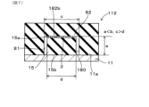
センサ3は、第一座面シートクッション12の収容凹部80内に形成された第一押圧面82bと、第二座面シートクッション15の第二押圧面15aと、の間に配置される。第一押圧面82bは、後述する凸部82aに設けられている。ここで、着座者がシート本体2に着座することにより、着座者の臀部から第一座面シートクッション12の受圧面12aに圧力が付与され、当該圧力が第一座面シートクッション12を介して第一座面シートクッション12の第一押圧面82bに伝達される。そして、第一座面シートクッション12の第一押圧面82bからセンサ3が圧力を受ける。つまり、センサ3は、着座者による着座状態において、第一座面シートクッション12の受圧面12aから第一座面シートクッション12を介して伝達される圧力に応じた物理量を検出する。そして、センサ3は、検出した物理量に基づいて、着座者の着座状態または着座者の生体情報を検出する。
The sensor 3 is arranged between the first pressing surface 82b formed in the housing recess 80 of the first seat cushion 12 and the second pressing surface 15a of the second seat cushion 15. The first pressing surface 82b is provided on a later-described convex portion 82a. Here, when the seated person sits on the seat body 2, pressure is applied from the buttocks of the seated person to the pressure receiving surface 12a of the first seat cushion 12, and the pressure is applied through the first seat cushion 12. It is transmitted to the first pressing surface 82b of the first seating surface seat cushion 12 . Then, the sensor 3 receives pressure from the first pressing surface 82 b of the first seat cushion 12 . That is, the sensor 3 detects a physical quantity corresponding to the pressure transmitted from the pressure receiving surface 12a of the first seat cushion 12 via the first seat cushion 12 when the person is seated. Then, the sensor 3 detects the seating state of the seated person or the biological information of the seated person based on the detected physical quantity.
ここで、センサ3は、シート座面部2aに配置したが、シート背面部2bに配置しても良い。この場合、センサ3は、背面シートフレーム21と背面シートクッション22との間に配置される。そして、センサ3は、着座者による着座状態において、背面シートクッション22の受圧面12aから背面シートクッション22を介して伝達される圧力に応じた物理量を検出する。そして、センサ3は、検出した物理量に基づいて、着座者の着座状態または着座者の生体情報を検出することができる。
Although the sensor 3 is arranged on the seat surface portion 2a here, it may be arranged on the seat back surface portion 2b. In this case, the sensor 3 is arranged between the rear seat frame 21 and the rear seat cushion 22 . The sensor 3 detects a physical quantity corresponding to the pressure transmitted from the pressure receiving surface 12a of the back seat cushion 22 through the back seat cushion 22 when the seated person is seated. Then, the sensor 3 can detect the seating state of the seated person or the biological information of the seated person based on the detected physical quantity.
1-2.センサ3の構成
センサ3の構成について、図2および図3を参照して説明する。図2および図3は、センサ3単体、すなわち、シート本体2に組付ける前のセンサ3を示す。 1-2. Configuration ofSensor 3 The configuration of the sensor 3 will be described with reference to FIGS. 2 and 3. FIG. 2 and 3 show the sensor 3 alone, that is, the sensor 3 before assembly to the seat body 2. FIG.
センサ3の構成について、図2および図3を参照して説明する。図2および図3は、センサ3単体、すなわち、シート本体2に組付ける前のセンサ3を示す。 1-2. Configuration of
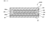
センサ3は、可撓性を有する扁平なシート状に形成されている。センサ3は、第一面36aおよび第二面36bを有する絶縁体シート36と、絶縁体シート36の第一面36aに積層される第一電極シート32と、第一電極シート32を覆う第一フィルムシート30と、絶縁体シート36の第二面36bに積層される第二電極シート37と、第二電極シート37を覆う第二フィルムシート41と、を備える。以下において、積層方向とは、特に断らない限り、センサ3を構成する、第一フィルムシート30、第一電極シート32、絶縁体シート36、第二電極シート37および第二フィルムシート41の積層方向として用いる。
The sensor 3 is formed in a flexible flat sheet shape. The sensor 3 includes an insulator sheet 36 having a first surface 36a and a second surface 36b, a first electrode sheet 32 laminated on the first surface 36a of the insulator sheet 36, and a first electrode sheet 32 covering the first electrode sheet 32. A film sheet 30 , a second electrode sheet 37 laminated on the second surface 36 b of the insulator sheet 36 , and a second film sheet 41 covering the second electrode sheet 37 are provided. In the following, the lamination direction means the lamination direction of the first film sheet 30, the first electrode sheet 32, the insulator sheet 36, the second electrode sheet 37, and the second film sheet 41, which constitute the sensor 3, unless otherwise specified. used as
絶縁体シート36は、絶縁性を有するとともに、可撓性を有しており、シート状(膜状)に形成されている。絶縁体シート36は、例えば、矩形状に形成される。絶縁体シート36を構成する材料は特に限定されないが、樹脂、またはエラストマーから構成されてもよい。樹脂としては、ポリオレフィン系、ポリアミド系が例示される。エラストマーとしては、ウレタン系、アクリル系、エステル系、ポリアミド系、オレフィン系、スチレン系が例示される。絶縁体シート36がエラストマー製である場合には、絶縁体シート36は弾性変形可能とされる。
The insulator sheet 36 has insulation and flexibility, and is formed in a sheet shape (membrane shape). The insulator sheet 36 is formed, for example, in a rectangular shape. The material forming the insulator sheet 36 is not particularly limited, but it may be made of resin or elastomer. Examples of resins include polyolefins and polyamides. Examples of elastomers include urethane, acrylic, ester, polyamide, olefin, and styrene. When the insulator sheet 36 is made of elastomer, the insulator sheet 36 is elastically deformable.
第一電極シート32は、可撓性を有しており、シート状(膜状)に形成されている。第一電極シート32は、例えば、矩形状をなす第一本体部32aと、当該矩形状の一辺から1箇所延在する第一耳部32bと、を備える。第一電極シート32は、絶縁体シート36の第一面36aと対向する面(図2の下面)に配置された第一電極層34を備える。第一電極層34は、絶縁体シート36の第一面36aと第二面36bにそれぞれ配される、一対の電極の一方を構成する。本形態においては、第一電極層34は、1枚の電極により構成されている。第一耳部32bには、第一電極層34と電気的に接続されるとともに、外部回路と電気的に接続される第一端子部35が設けられている。
The first electrode sheet 32 is flexible and formed in a sheet shape (film shape). The first electrode sheet 32 includes, for example, a rectangular first body portion 32a and a first ear portion 32b extending from one side of the rectangular shape. The first electrode sheet 32 has a first electrode layer 34 disposed on a surface (lower surface in FIG. 2) facing the first surface 36a of the insulator sheet 36 . The first electrode layer 34 constitutes one of a pair of electrodes disposed on the first surface 36a and the second surface 36b of the insulator sheet 36, respectively. In this embodiment, the first electrode layer 34 is composed of one electrode. The first ear portion 32b is provided with a first terminal portion 35 electrically connected to the first electrode layer 34 and electrically connected to an external circuit.
第一フィルムシート30は、絶縁性があって、可撓性を有しており、シート状(膜状)に形成されている。第一フィルムシート30は、公知の樹脂、またはエラストマーから構成される。第一フィルムシート30は、例えば、矩形状に形成されている。第一フィルムシート30は、第一電極シート32のうち絶縁体シート36と反対側の面を覆っている。これにより、第一電極シート32に応力が加えられたときに、第一電極シート32を保護するようになっている。第一フィルムシート30を構成する材料としては、絶縁体シート36を構成する材料と同じであってもよいし、また、異なっていてもよい。第一フィルムシート30を構成する材料が硬質材料である場合には、第一電極シート32を保護することができる。第一フィルムシート30のうち、第一電極シート32と反対側の面は、第一座面シートクッション12からの圧力をうける圧力検出面31とされる。
The first film sheet 30 is insulative, flexible, and formed in a sheet shape (membrane shape). The first film sheet 30 is made of known resin or elastomer. The first film sheet 30 is, for example, rectangular. The first film sheet 30 covers the surface of the first electrode sheet 32 opposite to the insulator sheet 36 . This protects the first electrode sheet 32 when stress is applied to the first electrode sheet 32 . The material forming the first film sheet 30 may be the same as or different from the material forming the insulator sheet 36 . When the material forming the first film sheet 30 is a hard material, the first electrode sheet 32 can be protected. The surface of the first film sheet 30 opposite to the first electrode sheet 32 serves as a pressure detection surface 31 that receives pressure from the first seat cushion 12 .
第二電極シート37は、第一電極シート32とは別体に構成されており、第一電極シート32の裏面に対向して配置される。第二電極シート37は、矩形状をなす第二本体部37aと、当該矩形状の一辺から1箇所延在する第二耳部37bと、を備える。第二電極シート37と第一電極シート32との間には絶縁体シート36が介在している。第二電極シート37は、可撓性を有しており、シート状(膜状)に形成されている。第二電極シート37は、絶縁体シート36の第二面36bと対向する面(図2の上面)に配置された第二電極層39を備える。第二電極層39は、第一電極シート32を構成する第一電極層34に対して距離を隔てて対向して配置される。つまり、第一電極層34と第二電極層39とは、積層方向の投影において、重なるように配置されている。第二電極層39は、静電センサまたは圧電センサにおける一対の電極の他方を構成する。
The second electrode sheet 37 is configured separately from the first electrode sheet 32 and arranged to face the back surface of the first electrode sheet 32 . The second electrode sheet 37 includes a rectangular second body portion 37a and a second ear portion 37b extending from one side of the rectangular shape. An insulator sheet 36 is interposed between the second electrode sheet 37 and the first electrode sheet 32 . The second electrode sheet 37 has flexibility and is formed in a sheet shape (film shape). The second electrode sheet 37 includes a second electrode layer 39 arranged on a surface (upper surface in FIG. 2) facing the second surface 36 b of the insulator sheet 36 . The second electrode layer 39 is arranged to face the first electrode layer 34 forming the first electrode sheet 32 with a distance therebetween. That is, the first electrode layer 34 and the second electrode layer 39 are arranged so as to overlap each other when projected in the stacking direction. The second electrode layer 39 constitutes the other of the pair of electrodes in the electrostatic sensor or piezoelectric sensor.
また、本形態においては、第二電極層39は、複数の電極群により構成されており、複数の電極群を構成する各電極が、第一電極シート32を構成する1枚の第一電極層34に対向するように層方向に配列される。本形態においては、図2に示すように、例えば、第二電極層39は、4行×4列に配列された16個の第二電極により構成される。ただし、第二電極層39を構成する第二電極群の数は、任意に設定できる。また、第二電極シート37は、第二電極層39の他に、プリントパターンを備える。第二耳部37bには、第二電極層39と電気的に接続されるとともに、外部回路と電気的に接続される第二端子部40が設けられている。
In this embodiment, the second electrode layer 39 is composed of a plurality of electrode groups, and each electrode constituting the plurality of electrode groups constitutes one first electrode layer constituting the first electrode sheet 32. 34 are arranged in the layer direction. In this embodiment, as shown in FIG. 2, for example, the second electrode layer 39 is composed of 16 second electrodes arranged in 4 rows×4 columns. However, the number of second electrode groups forming the second electrode layer 39 can be set arbitrarily. Also, the second electrode sheet 37 has a printed pattern in addition to the second electrode layer 39 . The second ear portion 37b is provided with a second terminal portion 40 that is electrically connected to the second electrode layer 39 and electrically connected to an external circuit.
第二フィルムシート41は、絶縁性であって、可撓性を有しており、シート状(膜状)に形成されている。第二フィルムシート41は、樹脂、またはエラストマーから構成される。第二フィルムシート41は、例えば、矩形状に形成されている。第二フィルムシート41は、第二電極シート37のうち絶縁体シート36と反対側の面を覆っている。これにより、第二電極シート37に応力が加えられたときに第二電極シート37を保護するようになっている。第二フィルムシート41を構成する材料としては、絶縁体シート36を構成する材料と同じであってもよいし、また、異なっていてもよい。第二フィルムシート41を構成する材料が硬質材料である場合には、第二電極シート37を保護することができる。
The second film sheet 41 is insulative, flexible, and formed in a sheet shape (membrane shape). The second film sheet 41 is made of resin or elastomer. The second film sheet 41 is, for example, rectangular. The second film sheet 41 covers the surface of the second electrode sheet 37 opposite to the insulator sheet 36 . This protects the second electrode sheet 37 when stress is applied to the second electrode sheet 37 . The material forming the second film sheet 41 may be the same as or different from the material forming the insulator sheet 36 . When the material forming the second film sheet 41 is a hard material, the second electrode sheet 37 can be protected.
なお、第一電極層34および第二電極層39は、それぞれ1枚の電極により構成されるようにしても良い。また、第一電極層34および第二電極層39が、それぞれ複数の電極により構成されるようにしても良い。例えば、第一電極層34を構成する複数の電極と第二電極層39を構成する複数の電極との対向位置が、1列に配列するように構成されていてもよいし、マトリックス状に配列するように構成されていてもよい。
Note that the first electrode layer 34 and the second electrode layer 39 may each be composed of one electrode. Also, the first electrode layer 34 and the second electrode layer 39 may each be composed of a plurality of electrodes. For example, the opposing positions of the plurality of electrodes forming the first electrode layer 34 and the plurality of electrodes forming the second electrode layer 39 may be arranged in a line or in a matrix. may be configured to
1-3.第一座面シートクッション12および第二座面シートクッション15の構成
第一座面シートクッション12および第二座面シートクッション15の構成について図4および図5を参照して説明する。図4は、第一座面シートクッション12に、センサ3および第二座面シートクッション15が組付けられる前の状態を示すものであり、図5は、第一座面シートクッション12に、センサ3および第二座面シートクッション15が組付けられた後の状態を示すものである。 1-3. Configuration ofFirst Seat Cushion 12 and Second Seat Cushion 15 The configuration of the first seat cushion 12 and the second seat cushion 15 will be described with reference to FIGS. 4 and 5. FIG. FIG. 4 shows a state before the sensor 3 and the second seat cushion 15 are assembled to the first seat cushion 12, and FIG. 3 and the second seat cushion 15 are assembled.
第一座面シートクッション12および第二座面シートクッション15の構成について図4および図5を参照して説明する。図4は、第一座面シートクッション12に、センサ3および第二座面シートクッション15が組付けられる前の状態を示すものであり、図5は、第一座面シートクッション12に、センサ3および第二座面シートクッション15が組付けられた後の状態を示すものである。 1-3. Configuration of
第一座面シートクッション12は、反受圧面12bに形成された収容凹部80を備える。収容凹部80は、第一座面シートクッション12の受圧面12aとは反対側、すなわち座面シートフレーム11側に開口する。収容凹部80は、センサ3を収容する。
The first seating surface seat cushion 12 has a housing recess 80 formed in the anti-pressure receiving surface 12b. The accommodation recess 80 opens on the side opposite to the pressure receiving surface 12 a of the first seat cushion 12 , that is, on the seat frame 11 side. The accommodation recess 80 accommodates the sensor 3 .
収容凹部80の開口部の形状は、センサ3の外形状よりも大きく形成されている。収容凹部80の開口部の形状は限定されないが、例えば、センサ3の外形状よりも大きな矩形状に形成される。また、収容凹部80の内周壁81も、矩形状に形成される。内周壁81は、センサ3の外周面の形状に対応するとともに、センサ3の外形状よりも大きく形成される。
The shape of the opening of the accommodation recess 80 is formed to be larger than the outer shape of the sensor 3 . Although the shape of the opening of the accommodation recess 80 is not limited, for example, it is formed in a rectangular shape that is larger than the outer shape of the sensor 3 . An inner peripheral wall 81 of the housing recess 80 is also formed in a rectangular shape. The inner peripheral wall 81 corresponds to the shape of the outer peripheral surface of the sensor 3 and is formed larger than the outer shape of the sensor 3 .
収容凹部80の底部82は、凸部82a、および、凹溝82cを有する。凸部82aは、底部82の中央付近に形成される。凸部82aは、収容凹部80の底部82から、収容凹部80の開口に向かって突出する。つまり、凸部82aは、底部82から座面シートフレーム11側に突出する。また、凸部82aの外側面と、収容凹部80の内側面との間には、隙間が形成されている。
The bottom 82 of the accommodation recess 80 has a projection 82a and a recess 82c. The convex portion 82 a is formed near the center of the bottom portion 82 . The protrusion 82 a protrudes from the bottom 82 of the accommodation recess 80 toward the opening of the accommodation recess 80 . That is, the convex portion 82a protrudes from the bottom portion 82 toward the seat frame 11 side. A gap is formed between the outer surface of the projection 82 a and the inner surface of the housing recess 80 .
本形態においては、凸部82aは、単一の弾性率を有する弾性材料により構成される。凸部82aは、第一座面シートクッション12を構成する弾性材料により形成される。つまり、凸部82aの弾性率は、第一座面シートクッション12を構成する他の部位の弾性率に等しい。
In this embodiment, the convex portion 82a is made of an elastic material having a single elastic modulus. The convex portion 82 a is made of an elastic material that constitutes the first seat cushion 12 . In other words, the elastic modulus of the convex portion 82 a is equal to the elastic modulus of the other parts that constitute the first seat cushion 12 .
凹溝82cは、凸部82aの周縁に沿って形成される。つまり、凹溝82cは、収容凹部80の内側面と凸部82aとの境界部分を構成し、凸部82aの周縁全周に亘って形成される。
The concave groove 82c is formed along the periphery of the convex portion 82a. That is, the concave groove 82c constitutes a boundary portion between the inner side surface of the accommodation concave portion 80 and the convex portion 82a, and is formed along the entire periphery of the convex portion 82a.
第二座面シートクッション15は、全体として直方体形状をなしている。第二座面シートクッション15は、座面シートフレーム11に取り付けられる取り付け面15bと、取り付け面15bと反対側に位置する第二押圧面15aと、を有する。第二押圧面15aには、センサ3が積層された状態で固定されている。センサ3は、第二押圧面15aに接着、熱融着等の公知の手法により固定されている。
The second seat cushion 15 has a cuboid shape as a whole. The second seat cushion 15 has an attachment surface 15b attached to the seat frame 11 and a second pressing surface 15a located on the opposite side of the attachment surface 15b. The sensors 3 are stacked and fixed to the second pressing surface 15a. The sensor 3 is fixed to the second pressing surface 15a by a known technique such as adhesion or heat fusion.
第一座面シートクッション12と、第二座面シートクッション15とは、センサ3において定義された積層方向に沿って積層されている。
The first seat cushion 12 and the second seat cushion 15 are stacked along the stacking direction defined by the sensor 3 .
第二座面シートクッション15は、第一座面シートクッション12と同じ材料により形成されてもよいし、また、異なる材料により形成されてもよい。また、第二座面シートクッション15の弾性率と、第一座面シートクッション12の弾性率は、同じであってもよいし、また、異なっていてもよい。後に詳述するが、第二座面シートクッション15の弾性率を、第一座面シートクッション12の弾性率と異ならせることにより、センサ3に加えられる圧力を調節することができる。
The second seat cushion 15 may be made of the same material as the first seat cushion 12, or may be made of a different material. Further, the elastic modulus of the second seat cushion 15 and the elastic modulus of the first seat cushion 12 may be the same or different. As will be described in detail later, by making the elastic modulus of the second seat cushion 15 different from the elastic modulus of the first seat cushion 12, the pressure applied to the sensor 3 can be adjusted.
第一座面シートクッション12の弾性率と、第二座面シートクッション15の弾性率とを異ならせる手段としては、例えば、第一座面シートクッション12を形成する材料と、第二座面シートクッション15を形成する材料とを異ならせてもよいし、また、第一座面シートクッション12の空隙率と、第二座面シートクッション15の空隙率とを異ならせてもよい。また、第一座面シートクッション12、および第二座面シートクッション15に添加されるフィラーにつき、フィラーの種類や、フィラーの添加量を、第一座面シートクッション12と第二座面シートクッション15とで異ならせてもよい。上記のように、任意の手段により、第一座面シートクッション12の弾性率と、第二座面シートクッション15の弾性率とを異ならせることができる。
Means for differentiating the modulus of elasticity of the first seat cushion 12 and the modulus of elasticity of the second seat cushion 15 include, for example, the material forming the first seat cushion 12 and the second seat cushion. The material forming the cushion 15 may be different, and the porosity of the first seat cushion 12 and the porosity of the second seat cushion 15 may be different. In addition, regarding the filler added to the first seat cushion 12 and the second seat cushion 15, the type of filler and the amount of filler added are 15 may be different. As described above, the modulus of elasticity of the first seat cushion 12 and the modulus of elasticity of the second seat cushion 15 can be made different by any means.
第二座面シートクッション15が収容凹部80内に収容された状態で、センサ3は、凸部82aの第一押圧面82bと、第二座面シートクッション15の第二押圧面15aとの間に挟まれた状態になっている。第二座面シートクッション15が収容凹部80内に収容された状態では、凸部82aは、収容凹部80の凸部82aは、センサ3に向かって突出するようになっている。凸部82aは、センサ3の圧力検出面31に直接的に圧力を与えるようになっている。センサ3の面積は、第一押圧面82bの面積、および第二押圧面15aの面積よりも小さく設定されている。
With the second seat cushion 15 accommodated in the accommodation recess 80, the sensor 3 is positioned between the first pressing surface 82b of the convex portion 82a and the second pressing surface 15a of the second seat cushion 15. is sandwiched between When the second seat cushion 15 is housed in the housing recess 80 , the projection 82 a of the housing recess 80 protrudes toward the sensor 3 . The convex portion 82 a directly applies pressure to the pressure detection surface 31 of the sensor 3 . The area of the sensor 3 is set smaller than the area of the first pressing surface 82b and the area of the second pressing surface 15a.
第二座面シートクッション15のうち第二押圧面15aを有する端部の形状、及び取り付け面15bを構成する端部の形状は、収容凹部80の凸部82aの形状と実質的に同じに設定されている。実質的に同じとは、同じである場合を含むとともに、同じでなくとも実質的に同一であると認定しうる場合も含む。以下、同様とする。第二座面シートクッション15が収容凹部80内に収容された状態で、第二座面シートクッション15の外側面と、収容凹部80の内側面との間には、隙間を有するようになっている。
The shape of the end of the second seat cushion 15 having the second pressing surface 15a and the shape of the end forming the mounting surface 15b are set to be substantially the same as the shape of the projection 82a of the accommodation recess 80. It is "Substantially the same" includes the case of being the same, and also includes the case of being recognized as being substantially the same even if it is not the same. The same shall apply hereinafter. When the second seat cushion 15 is accommodated in the accommodation recess 80, there is a gap between the outer surface of the second seat cushion 15 and the inner surface of the accommodation recess 80. there is
収容凹部80と第二座面シートクッション15とが組付けられる前の状態における、収容凹部80,および第二座面シートクッション15の各種寸法について図4を参照して説明する。収容凹部80の開口の幅寸法はcである。凸部82aの幅寸法、および第二座面シートクッション15の幅寸法はdである。第一座面シートクッション12と第二座面シートクッション15との積層方向について、収容凹部80の反受圧面12bから凸部82aの先端部までの深さ寸法は、aである。また、第二座面シートクッション15の厚さ寸法と、センサ3の厚さ寸法との和は、bである。
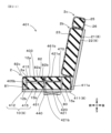
Various dimensions of the accommodation recess 80 and the second seat cushion 15 before the accommodation recess 80 and the second seat cushion 15 are assembled will be described with reference to FIG. The width dimension of the opening of the accommodation recess 80 is c. The width dimension of the protrusion 82a and the width dimension of the second seat cushion 15 are d. In the stacking direction of the first seat cushion 12 and the second seat cushion 15, the depth dimension from the pressure-receiving surface 12b of the housing recess 80 to the tip of the protrusion 82a is a. The sum of the thickness dimension of the second seat cushion 15 and the thickness dimension of the sensor 3 is b.
第一座面シートクッション12と第二座面シートクッション15とが組付けられる前の状態においては、
a < b
とされている。換言すると、第一座面シートクッション12と第二座面シートクッション15との積層方向について、第二座面シートクッション15の厚さ寸法と、センサ3の厚さ寸法との和bは、収容凹部80の反受圧面12bから凸部82aの先端部までの深さ寸法aよりも大きく設定されている。 Before thefirst seat cushion 12 and the second seat cushion 15 are assembled,
a < b
It is said that In other words, in the stacking direction of thefirst seat cushion 12 and the second seat cushion 15, the sum b of the thickness dimension of the second seat cushion 15 and the thickness dimension of the sensor 3 is It is set larger than the depth dimension a from the pressure-receiving surface 12b of the concave portion 80 to the tip of the convex portion 82a.
a < b
とされている。換言すると、第一座面シートクッション12と第二座面シートクッション15との積層方向について、第二座面シートクッション15の厚さ寸法と、センサ3の厚さ寸法との和bは、収容凹部80の反受圧面12bから凸部82aの先端部までの深さ寸法aよりも大きく設定されている。 Before the
a < b
It is said that In other words, in the stacking direction of the
また、第一座面シートクッション12と第二座面シートクッション15とが組付けられる前の状態において、
c > d
とされている。換言すると、第一座面シートクッション12と第二座面シートクッション15とが組付けられる前の状態において、第二座面シートクッション15の幅寸法dは、収容凹部80の開口の幅寸法cよりも小さく設定されている。 Further, in a state before thefirst seat cushion 12 and the second seat cushion 15 are assembled,
c > d
It is said that In other words, before thefirst seat cushion 12 and the second seat cushion 15 are assembled, the width dimension d of the second seat cushion 15 is equal to the width dimension c of the opening of the accommodation recess 80. is set smaller than
c > d
とされている。換言すると、第一座面シートクッション12と第二座面シートクッション15とが組付けられる前の状態において、第二座面シートクッション15の幅寸法dは、収容凹部80の開口の幅寸法cよりも小さく設定されている。 Further, in a state before the
c > d
It is said that In other words, before the
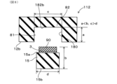
次に、第二座面シートクッション15が収容凹部80内に収容され、さらに、座面シートフレーム11に取り付けられた状態における、収容凹部80,および第二座面シートクッション15の各種寸法について図5を参照して説明する。
Next, various dimensions of the accommodation recess 80 and the second seat cushion 15 in a state where the second seat cushion 15 is accommodated in the accommodation recess 80 and attached to the seat frame 11 are shown. 5 for explanation.
第二座面シートクッション15は、凸部82aと、座面シートフレーム11との間に挟まれることにより、収縮する。この結果、第二座面シートクッション15の厚さ寸法とセンサ3の厚さ寸法の和は、第一座面シートクッション12の反受圧面12bから凸部82aの第一押圧面82bまでの深さ寸法aと同じになっている。これにより、センサ3の圧力検出面31には、凸部82aの第一押圧面82b、および第二座面シートクッション15の第二押圧面15aによって予圧縮される。この時の予圧縮量は、第一座面シートクッション12の弾発力と、第二座面シートクッション15の弾発力に基づく。
The second seat cushion 15 shrinks by being sandwiched between the convex portion 82a and the seat frame 11. As a result, the sum of the thickness dimension of the second seat cushion 15 and the thickness dimension of the sensor 3 is the depth from the anti-pressure surface 12b of the first seat cushion 12 to the first pressing surface 82b of the projection 82a. It is the same as the length dimension a. As a result, the pressure detecting surface 31 of the sensor 3 is pre-compressed by the first pressing surface 82b of the projection 82a and the second pressing surface 15a of the second seat cushion 15 . The amount of precompression at this time is based on the elastic force of the first seat cushion 12 and the elastic force of the second seat cushion 15 .
一方、座面シートフレーム11に対する予圧縮量は、例えば、第一座面シートクッション12の自重による程度である。このため、凸部82aによるセンサ3の圧力検出面31に対する予圧縮量は、第一座面シートクッション12による座面シートフレーム(圧力検出面31の周囲に相当)に対する予圧縮量よりも大きく設定されている。従って、第二座面シートクッション15が収容凹部80内に収容され、さらに、座面シートフレーム11に取り付けられた状態において、センサ3の圧力検出面31は、凸部82aから、第一座面シートクッション12の自重に比べて大きな圧力を受けている。
On the other hand, the amount of precompression for the seat frame 11 is, for example, the weight of the first seat cushion 12 itself. Therefore, the amount of precompression of the pressure detection surface 31 of the sensor 3 by the convex portion 82a is set larger than the amount of precompression of the seat frame (corresponding to the periphery of the pressure detection surface 31) by the first seat cushion 12. It is Therefore, in a state where the second seat cushion 15 is accommodated in the accommodation recess 80 and attached to the seat frame 11, the pressure detection surface 31 of the sensor 3 moves from the projection 82a to the first seat surface. The seat cushion 12 receives a large pressure compared to its own weight.
図5に示すように、第二座面シートクッション15が収容凹部80内に収容され、さらに、座面シートフレーム11に取り付けられた状態においても、
c > d
とされており、第二座面シートクッション15幅寸法dは、収容凹部80の開口の幅寸法よりも小さく設定されている。つまり、第二座面シートクッション15の外側面と、収容凹部80の内側面との間には隙間が形成されている。 As shown in FIG. 5, even when thesecond seat cushion 15 is accommodated in the accommodation recess 80 and attached to the seat frame 11,
c > d
The width dimension d of thesecond seat cushion 15 is set smaller than the width dimension of the opening of the accommodation recess 80 . That is, a gap is formed between the outer surface of the second seat cushion 15 and the inner surface of the accommodation recess 80 .
c > d
とされており、第二座面シートクッション15幅寸法dは、収容凹部80の開口の幅寸法よりも小さく設定されている。つまり、第二座面シートクッション15の外側面と、収容凹部80の内側面との間には隙間が形成されている。 As shown in FIG. 5, even when the
c > d
The width dimension d of the
1-4.センサ付きシート1の詳細構成
センサ付きシート1の詳細構成として、主として、センサ3と収容凹部80との組付状態について、図5を参照して説明する。図5には、着座者がシート本体2に着座していない状態を示す。従って、以下においては、着座者がシート本体2に着座していない状態について説明する。 1-4. Detailed Configuration ofSeat 1 with Sensor As a detailed configuration of the seat 1 with sensor, mainly the assembly state of the sensor 3 and the accommodation recess 80 will be described with reference to FIG. FIG. 5 shows a state in which the seated person is not seated on the seat body 2 . Therefore, the state in which the seated person is not seated on the seat body 2 will be described below.
センサ付きシート1の詳細構成として、主として、センサ3と収容凹部80との組付状態について、図5を参照して説明する。図5には、着座者がシート本体2に着座していない状態を示す。従って、以下においては、着座者がシート本体2に着座していない状態について説明する。 1-4. Detailed Configuration of
座面シートフレーム11に第一座面シートクッション12が固定される。従って、第一座面シートクッション12の反受圧面12bにおける収容凹部80の周囲が、座面シートフレーム11に対して僅かに予圧縮された状態で、座面シートフレーム11に接触する。
A first seat cushion 12 is fixed to the seat frame 11 . Therefore, the periphery of the accommodation recess 80 in the pressure-receiving surface 12 b of the first seat cushion 12 contacts the seat frame 11 while being slightly pre-compressed with respect to the seat frame 11 .
センサ3は、第一座面シートクッション12の第一押圧面82bと、第二座面シートクッション15の第二押圧面15aとの間に配置されている。第二座面シートクッション15は座面シートフレーム11に取り付けられる。
The sensor 3 is arranged between the first pressing surface 82b of the first seat cushion 12 and the second pressing surface 15a of the second seat cushion 15. The second seat cushion 15 is attached to the seat frame 11 .
さらに、センサ3は、第一座面シートクッション12の収容凹部80に収容される。収容凹部80の凸部82aの先端面が、センサ3の圧力検出面31と接触する。つまり、センサ3の圧力検出面31は、第一座面シートクッション12における凸部82aから圧力を受ける。なお、センサ3は、圧力検出面31が受けた圧力に応じた物理量を検出する。
Furthermore, the sensor 3 is housed in the housing recess 80 of the first seat cushion 12 . The tip surface of the protrusion 82 a of the accommodation recess 80 contacts the pressure detection surface 31 of the sensor 3 . That is, the pressure detection surface 31 of the sensor 3 receives pressure from the convex portion 82 a of the first seat cushion 12 . In addition, the sensor 3 detects a physical quantity according to the pressure received by the pressure detection surface 31 .
さらに、上記したように、第一座面シートクッション12と第二座面シートクッション15とが取り付けられる前の状態においては、第二座面シートクッション15の厚さ寸法と、センサ3の厚さ寸法との和bは、収容凹部80の反受圧面12bから凸部82aの先端部までの深さ寸法aよりも大きく設定されている。第二座面シートクッション15が収容凹部80内に収容され、さらに、座面シートフレーム11に取り付けられた状態においては、第二座面シートクッション15の厚さ寸法とセンサ3の厚さ寸法の和は、第一座面シートクッションの反受圧面12bから凸部82aの第一押圧面82bまでの深さ寸法aと同じになっていることから、凸部82aは、センサ3の圧力検出面31に対して予圧縮されている。特に、凸部82aによるセンサ3の圧力検出面31に対する予圧縮量は、第一座面シートクッション12による座面シートフレーム11(圧力検出面31の周囲に相当)に対する予圧縮量よりも十分に大きく設定されている。従って、センサ3の圧力検出面31は、凸部82aから、第一座面シートクッション12の自重に比べて大きな圧力を受けている。
Furthermore, as described above, before the first seat cushion 12 and the second seat cushion 15 are attached, the thickness dimension of the second seat cushion 15 and the thickness of the sensor 3 The sum b with the dimension is set larger than the depth dimension a from the anti-pressure receiving surface 12b of the housing recess 80 to the tip of the projection 82a. When the second seat cushion 15 is accommodated in the accommodation recess 80 and attached to the seat frame 11, the thickness dimension of the second seat cushion 15 and the thickness dimension of the sensor 3 are different. The sum is the same as the depth dimension a from the anti-pressure receiving surface 12b of the first seat cushion to the first pressing surface 82b of the projection 82a. 31 precompressed. In particular, the amount of precompression of the pressure detection surface 31 of the sensor 3 by the convex portion 82a is sufficiently larger than the amount of precompression of the first seat cushion 12 for the seat frame 11 (corresponding to the periphery of the pressure detection surface 31). set large. Therefore, the pressure detection surface 31 of the sensor 3 receives a large amount of pressure from the protrusion 82a compared to the weight of the first seat cushion 12 itself.
第一座面シートクッション12の収容凹部80内に第二座面シートクッション15を収容し、且つ第二座面シートクッション15に何も荷重を加えていない状態では、第二座面シートクッション15は、第一座面シートクッション12の反受圧面12bから突出した状態になっている。第二座面シートクッション15が第一座面シートクッション12から突出した状態の座面シートクッション10を、座面シートフレーム11の取り付け座面11aに取り付けることにより、未着座状態において、第一座面シートクッション12の反受圧面12bと、第二座面シートクッション15のうち取り付け座面11aに対向する取り付け面15bとを、面一にすることができる。これにより、第二座面シートクッション15を確実に圧縮させることができるので、第一座面シートクッション12および第二座面シートクッション15を確実に予圧縮させることができる。
In a state in which the second seat cushion 15 is accommodated in the accommodation recess 80 of the first seat cushion 12 and no load is applied to the second seat cushion 15, the second seat cushion 15 does not move. protrudes from the pressure-receiving surface 12 b of the first seat cushion 12 . By attaching the seat cushion 10 with the second seat cushion 15 protruding from the first seat cushion 12 to the mounting seat surface 11a of the seat frame 11, the first seat cushion 10 can be placed in the non-seated state. The pressure-receiving surface 12b of the front seat cushion 12 and the attachment surface 15b of the second seat cushion 15 facing the attachment seat surface 11a can be flush with each other. As a result, the second seat cushion 15 can be reliably compressed, so that the first seat cushion 12 and the second seat cushion 15 can be reliably precompressed.
1-5.センサ3の動作
センサ3の検出対象は、着座者の着座状態、例えば、着座姿勢の変化などである。着座者の着座姿勢の変化によって第一座面シートクッション12の変形状態が変わることによって、センサ3が、第一座面シートクッション12を介して伝達された圧力を受ける。具体的には、着座姿勢の変化によって、センサ3が第一座面シートクッション12の凸部82aから受ける圧力が変化する。つまり、センサ3は、変化した圧力に応じた物理量を検出し、この物理量に基づいて、着座者の着座姿勢の変化を検出する。 1-5. Operation ofSensor 3 The object to be detected by the sensor 3 is the seating state of the seated person, for example, changes in the sitting posture. The sensor 3 receives pressure transmitted through the first seat cushion 12 due to changes in the deformation state of the first seat cushion 12 due to changes in the seating posture of the occupant. Specifically, the pressure that the sensor 3 receives from the convex portion 82a of the first seat cushion 12 changes as the seating posture changes. That is, the sensor 3 detects a physical quantity corresponding to the changed pressure, and detects a change in the seating posture of the seated person based on this physical quantity.
センサ3の検出対象は、着座者の着座状態、例えば、着座姿勢の変化などである。着座者の着座姿勢の変化によって第一座面シートクッション12の変形状態が変わることによって、センサ3が、第一座面シートクッション12を介して伝達された圧力を受ける。具体的には、着座姿勢の変化によって、センサ3が第一座面シートクッション12の凸部82aから受ける圧力が変化する。つまり、センサ3は、変化した圧力に応じた物理量を検出し、この物理量に基づいて、着座者の着座姿勢の変化を検出する。 1-5. Operation of
また、センサ3の他の検出対象は、着座者の生体情報、例えば、呼吸、脈動、心拍などである。呼吸、脈動、心拍によって、着座者の皮膚表面に微小な振動が生じる。当該微小な振動によって、センサ3が、第一座面シートクッション12を介して伝達された圧力を受ける。具体的には、当該微小な振動によって、センサ3が第一座面シートクッション12の凸部82aから受ける圧力が変化する。つまり、センサ3は、変化した圧力に応じた物理量を出力し、この物理量に基づいて、着座者の生体情報を検出する。
In addition, other detection targets of the sensor 3 are the biological information of the seated person, such as respiration, pulsation, and heartbeat. Breathing, pulsation, and heartbeat cause minute vibrations on the skin surface of the seated person. The minute vibration causes the sensor 3 to receive pressure transmitted through the first seat cushion 12 . Specifically, the minute vibration changes the pressure that the sensor 3 receives from the convex portion 82 a of the first seat cushion 12 . That is, the sensor 3 outputs a physical quantity corresponding to the changed pressure, and detects the biological information of the seated person based on this physical quantity.
1-6.センサ3の配置による作用
センサ3は、座面シートフレーム11と第一座面シートクッション12の反受圧面12bとの間に配置されている。つまり、センサ3は、座面シートフレーム11に配置されている。従って、センサ3は、第一座面シートクッション12の中に配置される場合に比べて、安定した位置決めが可能となる。 1-6. Effect of Arrangement ofSensor 3 The sensor 3 is arranged between the seat frame 11 and the pressure-receiving surface 12 b of the first seat cushion 12 . That is, the sensor 3 is arranged on the seating surface seat frame 11 . Therefore, the sensor 3 can be positioned more stably than when it is arranged inside the first seat cushion 12 .
センサ3は、座面シートフレーム11と第一座面シートクッション12の反受圧面12bとの間に配置されている。つまり、センサ3は、座面シートフレーム11に配置されている。従って、センサ3は、第一座面シートクッション12の中に配置される場合に比べて、安定した位置決めが可能となる。 1-6. Effect of Arrangement of
センサ3は第一座面シートクッション12に設けられた収容凹部80内に収容されているので、座面シートフレーム11に取り付けられている場合に比べて、第一座面シートクッション12の受圧面12aに近い位置に配されている。これにより、着座者から発せられた生体信号が第一座面シートクッション12によって減衰することが抑制されるので、センサ3が受ける生体信号の強度を向上させることができる。
Since the sensor 3 is housed in the housing recess 80 provided in the first seat cushion 12 , the pressure receiving surface of the first seat cushion 12 is larger than when it is attached to the seat frame 11 . It is arranged at a position close to 12a. As a result, attenuation of the biological signal emitted from the seated person by the first seat cushion 12 is suppressed, so that the strength of the biological signal received by the sensor 3 can be improved.
また、センサ3と、座面シートフレーム11との間には、第二座面シートクッション15が介在しているので、車両からの振動ノイズを、第二座面シートクッション15によって減衰させることができる。
Further, since the second seat cushion 15 is interposed between the sensor 3 and the seat frame 11, vibration noise from the vehicle can be attenuated by the second seat cushion 15. can.
また、センサ3には、第一座面シートクッション12および第二座面シートクッション15の圧縮反力による予圧縮が付与されているので、着座者がシート本体2に着座した際に、着座者から座面シートクッション10に付与される力が小さいとしても、この力はセンサ3に伝達されることが可能となる。この結果、センサ3の感度を向上させることができる。
Further, since the sensor 3 is pre-compressed by the compression reaction force of the first seat cushion 12 and the second seat cushion 15, when the seat occupant is seated on the seat body 2, the seat occupant Therefore, even if the force applied to the seat cushion 10 is small, this force can be transmitted to the sensor 3 . As a result, the sensitivity of the sensor 3 can be improved.
1-7.センサが可撓性を有することによる作用
センサ3は可撓性を有するので、着座者が第一座面シートクッション12に着座したことによって第一座面シートクッション12が変形したとき、センサ3も第一座面シートクッション12の変形に追従して変形する。これにより、着座者からの圧力と異なるノイズの発生を抑制することができる。 1-7. Effect of the sensor having flexibility Since thesensor 3 has flexibility, when the first seat cushion 12 is deformed by the seated person sitting on the first seat cushion 12, the sensor 3 is also affected by the deformation. It deforms following the deformation of the first seat cushion 12 . As a result, it is possible to suppress the generation of noise that is different from the pressure from the seated person.
センサ3は可撓性を有するので、着座者が第一座面シートクッション12に着座したことによって第一座面シートクッション12が変形したとき、センサ3も第一座面シートクッション12の変形に追従して変形する。これにより、着座者からの圧力と異なるノイズの発生を抑制することができる。 1-7. Effect of the sensor having flexibility Since the
1-8.凸部82aの予圧縮による作用
センサ付きシート1において、センサ3による作用について説明する。上述したように、着座者がシート本体2に着座していない未着座状態において、第一座面シートクッション12は、センサ3の圧力検出面31に対する予圧縮量が、圧力検出面31の周囲(例えば、座面シートフレーム11)に対する予圧縮量よりも大きく設定されている。 1-8. Effect of Pre-Compression ofConvex Portion 82a The effect of the sensor 3 in the sensor-equipped seat 1 will be described. As described above, in the non-seated state in which the occupant is not seated on the seat body 2 , the precompression amount of the first seat cushion 12 with respect to the pressure detection surface 31 of the sensor 3 is around the pressure detection surface 31 ( For example, it is set larger than the amount of precompression for the seat frame 11).
センサ付きシート1において、センサ3による作用について説明する。上述したように、着座者がシート本体2に着座していない未着座状態において、第一座面シートクッション12は、センサ3の圧力検出面31に対する予圧縮量が、圧力検出面31の周囲(例えば、座面シートフレーム11)に対する予圧縮量よりも大きく設定されている。 1-8. Effect of Pre-Compression of
従って、未着座状態において、既に、第一座面シートクッション12における凸部82aには、他の部位に比べて大きな応力が生じている。凸部82aは、センサ3の圧力検出面31の法線方向に予圧縮されている。従って、第一座面シートクッション12においては、凸部82aにおいて最も大きな応力が生じており、凸部82aから第一座面シートクッション12の受圧面12aまでの範囲において他の部位に比べて大きな応力が生じている。そのため、センサ3には、未着座状態において、既に凸部82aから圧力を受けていることになる。
Therefore, in the non-seated state, the convex portion 82a of the first seat cushion 12 already has a greater stress than other portions. The convex portion 82 a is precompressed in the normal direction of the pressure detection surface 31 of the sensor 3 . Therefore, in the first seating surface seat cushion 12, the largest stress occurs in the convex portion 82a, and the stress in the range from the convex portion 82a to the pressure receiving surface 12a of the first seating surface seat cushion 12 is greater than that in other portions. There is stress. Therefore, the sensor 3 is already receiving pressure from the convex portion 82a in the non-seated state.
続いて、着座者がシート本体2に着座する場合を考える。着座者がシート本体2に着座することによって、着座者の臀部から第一座面シートクッション12に力が付与される。そうすると、第一座面シートクッション12が着座者の臀部および体重に応じて変形する。そして、着座状態においては、未着座状態に比べて、第一座面シートクッション12に生じる応力の大きさは変化する。ただし、着座状態においても、第一座面シートクッション12においては、凸部82aにおいて最も大きな応力が生じており、凸部82aから第一座面シートクッション12の受圧面12aまでの範囲において他の部位に比べて大きな応力が生じている。
Next, consider the case where the seated person sits on the seat body 2 . When the seated person sits on the seat body 2, force is applied to the first seat cushion 12 from the buttocks of the seated person. Then, the first seat cushion 12 is deformed according to the buttocks and weight of the seated person. In the seated state, the magnitude of the stress generated in the first seating surface seat cushion 12 changes compared to the non-seated state. However, even in the seated state, in the first seating surface seat cushion 12, the largest stress is generated in the convex portion 82a, and in the range from the convex portion 82a to the pressure receiving surface 12a of the first seating surface seat cushion 12, other stresses are applied. A large stress is generated compared to the part.
ここで、センサ3の検出対象の1つは、着座者の着座状態、例えば、着座姿勢の変化などである。また、センサ3の他の検出対象は、着座者の生体情報、例えば、呼吸、脈動、心拍などである。
Here, one of the detection targets of the sensor 3 is the seating state of the seated person, for example, changes in the sitting posture. Other detection targets of the sensor 3 are biological information of the seated person, such as respiration, pulsation, and heartbeat.
そして、センサ3の圧力検出面31が、第一座面シートクッション12の凸部82aから圧力を受けることにより、センサ3が、着座者の着座状態や生体情報を検出する。しかし、第一座面シートクッション12は、着座者から付与される力を吸収する。そのため、着座者の着座状態の変化や生体が発する振動によって、第一座面シートクッション12の受圧面12aに力が付与されたとしても、第一座面シートクッション12が全てを吸収してしまうと、センサ3が着座者の着座状態や生体情報を検出することができない。
Then, the pressure detection surface 31 of the sensor 3 receives pressure from the convex portion 82a of the first seat cushion 12, whereby the sensor 3 detects the seating state and biological information of the seated person. However, the first seat cushion 12 absorbs the force applied by the occupant. Therefore, even if force is applied to the pressure-receiving surface 12a of the first seat cushion 12 due to changes in the seated state of the seated person or vibrations generated by the living body, the first seat cushion 12 absorbs all of the force. As a result, the sensor 3 cannot detect the seating state and biological information of the seated person.
しかし、上述したように、センサ3の圧力検出面31には、未着座状態において、第一座面シートクッション12による予圧縮が付与されている。ただし、第一座面シートクッション12は、未着座状態において、センサ3の圧力検出面31の周囲(座面シートフレーム11)に対しても予圧縮を付与している。そして、第一座面シートクッション12は、未着座状態において、センサ3の圧力検出面31に対する予圧縮量が、圧力検出面31の周囲に対する予圧縮量よりも大きく設定されている。
However, as described above, the pressure detection surface 31 of the sensor 3 is precompressed by the first seating surface seat cushion 12 in the non-seated state. However, the first seat cushion 12 also applies precompression to the periphery of the pressure detection surface 31 of the sensor 3 (the seat frame 11) in the non-seated state. In the first seating surface seat cushion 12, the amount of precompression of the pressure detection surface 31 of the sensor 3 is set to be larger than the amount of precompression of the periphery of the pressure detection surface 31 in the non-seated state.
このように、センサ3の圧力検出面31に対する予圧縮量が周囲よりも大きく設定されることで、着座者がシート本体2に着座した際に、着座者から第一座面シートクッション12に付与される力が極めて小さいとしても、当該力が、センサ3の圧力検出面31に伝達される。従って、センサ3の圧力検出面31は、第一座面シートクッション12に付与される微小な圧力の変化を検出できる。
In this way, by setting the amount of precompression to the pressure detection surface 31 of the sensor 3 to be larger than the surroundings, when the occupant is seated on the seat body 2, the occupant applies pressure to the first seat cushion 12 from the occupant. Even if the applied force is very small, it is transmitted to the pressure sensing surface 31 of the sensor 3 . Therefore, the pressure detection surface 31 of the sensor 3 can detect minute changes in the pressure applied to the first seat cushion 12 .
つまり、着座者の着座状態が極めて僅かに変化した程度であったとしても、センサ3の圧力検出面31は、当該変化に伴って伝達される微小な圧力変化を検出することができる。従って、高精度に、着座者の着座状態を検出することができる。また、呼吸、脈動、心拍などの生体が発する振動に伴って、着座者から第一座面シートクッション12に付与される力の大きさは微小である。このような場合であっても、センサ3の圧力検出面31は、当該生体が発する振動に伴って伝達される微小な圧力変化を検出することができる。従って、高精度に、着座者の生体情報を検出することができる。
That is, even if the seating state of the seated person changes only slightly, the pressure detection surface 31 of the sensor 3 can detect a minute pressure change that is transmitted along with the change. Therefore, the seating state of the seated person can be detected with high accuracy. In addition, the magnitude of the force applied from the seated person to the first seat cushion 12 due to vibrations generated by the living body such as respiration, pulsation, and heartbeat is very small. Even in such a case, the pressure detection surface 31 of the sensor 3 can detect minute pressure changes that are transmitted along with the vibrations generated by the living body. Therefore, the biological information of the seated person can be detected with high accuracy.
特に、上述したように、未着座状態において、第一座面シートクッション12においては、凸部82aにおいて最も大きな応力が生じており、凸部82aから第一座面シートクッション12の受圧面12aまでの範囲において他の部位に比べて大きな応力が生じている。そのため、未着座状態において応力が生じている領域は、他の領域に比べて、力の伝達感度が高くなる。
In particular, as described above, in the first seat cushion 12 in the non-seated state, the largest stress is generated in the convex portion 82a, and the stress from the convex portion 82a to the pressure receiving surface 12a of the first seat cushion 12 is increased. Larger stress is generated in the range than other parts. Therefore, the area where stress is generated in the non-seated state has higher force transmission sensitivity than other areas.
従って、第一座面シートクッション12の受圧面12aに付与される力が微小であったとしても、微小な力が、第一座面シートクッション12の受圧面12aから凸部82aを介してセンサ3の圧力検出面31に至る範囲を、高感度に伝達される。その結果、高精度に、着座者の着座状態や生体情報を検出することができる。
Therefore, even if the force applied to the pressure-receiving surface 12a of the first seat cushion 12 is very small, the minute force is transmitted from the pressure-receiving surface 12a of the first seat cushion 12 through the projection 82a to the sensor. The range up to the pressure detection surface 31 of 3 is transmitted with high sensitivity. As a result, the seating state and biological information of the seated person can be detected with high accuracy.
また、着座者が着座する受圧面12aを有する第一座面シートクッション12については、着座者の座り心地を考慮した弾性率が設定されることが好ましい。一方、センサ3に付与される予圧縮量を考慮した場合には、座り心地が考慮された第一座面シートクッション12の弾性率が最適であるとは限らない。このような場合には、第二座面シートクッション15の弾性率を第一座面シートクッション12の弾性率と異ならせることにより、センサ3に付与される予圧縮量を適切に調節することができる。これにより、センサ3の感度を向上させることができる。
Also, for the first seat cushion 12 having the pressure-receiving surface 12a on which the seated person sits, the elastic modulus is preferably set in consideration of the seating comfort of the seated person. On the other hand, when the amount of precompression applied to the sensor 3 is taken into consideration, the elastic modulus of the first seat cushion 12, which is designed with sitting comfort in mind, is not always optimal. In such a case, by making the elastic modulus of the second seat cushion 15 different from the elastic modulus of the first seat cushion 12, the amount of precompression applied to the sensor 3 can be appropriately adjusted. can. Thereby, the sensitivity of the sensor 3 can be improved.
第一クッションは、収容凹部80の底部82に形成され、凸部82aの周縁に沿って形成され、凸部82aの外側面と、収容凹部80の内側面とを隔てる凹溝82cを備える。
The first cushion is formed in the bottom portion 82 of the housing recess 80 and includes a groove 82c that is formed along the periphery of the projection 82a and separates the outer surface of the projection 82a from the inner surface of the housing recess 80.
凸部82aの外側面と収容凹部80の内側面とが凹溝82cによって隔てられているので、着座者から第一クッションの受圧面12aに加えられた力が凸部82aからセンサ3に伝えられる際に、凸部82aの外側面と収容凹部80の内側面とが摺接することによって摩擦力が生じることを抑制できる。これにより、着座者から第一座面シートクッション12の受圧面12aに加えられた力が摩擦によって減衰することが抑制されるので、センサ3の感度を向上させることができる。
Since the outer surface of the projection 82a and the inner surface of the accommodation recess 80 are separated by the groove 82c, the force applied by the seated person to the pressure receiving surface 12a of the first cushion is transmitted from the projection 82a to the sensor 3. At this time, it is possible to suppress the generation of frictional force due to the sliding contact between the outer surface of the convex portion 82a and the inner surface of the housing recess 80. As shown in FIG. As a result, the force applied by the seated person to the pressure receiving surface 12a of the first seat cushion 12 is suppressed from attenuating due to friction, so the sensitivity of the sensor 3 can be improved.
また、第一座面シートクッション12が座面表皮部材13によって覆われていることにより、第一座面シートクッション12が外方に膨出するように変形することが抑制される。これにより、予圧縮された第一座面シートクッション12が外方に膨出することによって予圧縮量が減少してしまうことが抑制される。この結果、第一座面シートクッション12が座面表皮部材13によって覆われていない場合に比べて、センサ3の感度が低下することが抑制される。
In addition, since the first seat cushion 12 is covered with the seat upholstery member 13, deformation of the first seat cushion 12 so as to bulge outward is suppressed. As a result, the amount of pre-compression is prevented from decreasing due to the outward expansion of the pre-compressed first seat cushion 12 . As a result, compared with the case where the first seat cushion 12 is not covered with the seat upholstery member 13, the sensitivity of the sensor 3 is suppressed from deteriorating.
(実施形態2)
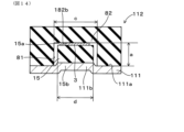
実施形態のセンサ付きシート1について、図6および図7を参照して説明する。本形態のセンサ付きシート1の第一座面シートクッション112は、凸部82aを有しない点で、実施形態1と相違する。収容凹部180の底面は、センサ3を押圧する第一押圧面182bとされる。なお、実施形態2以降において用いた符号のうち、既出の実施形態において用いた符号と同一のものは、特に示さない限り、既出の実施形態におけるものと同様の構成要素等を表す。 (Embodiment 2)
Asheet 1 with a sensor according to the embodiment will be described with reference to FIGS. 6 and 7. FIG. The first seat cushion 112 of the sensor-equipped seat 1 of this embodiment differs from that of the first embodiment in that it does not have the projection 82a. The bottom surface of the housing recess 180 serves as a first pressing surface 182 b that presses the sensor 3 . Note that, of the reference numerals used in the second and subsequent embodiments, the same reference numerals as those used in the previous embodiments represent the same constituent elements as those in the previous embodiments, unless otherwise specified.
実施形態のセンサ付きシート1について、図6および図7を参照して説明する。本形態のセンサ付きシート1の第一座面シートクッション112は、凸部82aを有しない点で、実施形態1と相違する。収容凹部180の底面は、センサ3を押圧する第一押圧面182bとされる。なお、実施形態2以降において用いた符号のうち、既出の実施形態において用いた符号と同一のものは、特に示さない限り、既出の実施形態におけるものと同様の構成要素等を表す。 (Embodiment 2)
A
図6に示すように、第一座面シートクッション112と第二座面シートクッション15との積層方向について、収容凹部180の反受圧面12bから第一押圧面182bまでの深さ寸法は、aである。また、第二座面シートクッション15の厚さ寸法と、センサ3の厚さ寸法との和は、bである。
As shown in FIG. 6, in the direction in which the first seat cushion 112 and the second seat cushion 15 are laminated, the depth dimension from the anti-pressure receiving surface 12b of the housing recess 180 to the first pressing surface 182b is a is. The sum of the thickness dimension of the second seat cushion 15 and the thickness dimension of the sensor 3 is b.
本形態においては、第一座面シートクッション112と第二座面シートクッション15とが組付けられる前の状態においては、
a < b
とされている。換言すると、第一座面シートクッション112と第二座面シートクッション15との積層方向について、第二座面シートクッション15の厚さ寸法と、センサ3の厚さ寸法との和bは、収容凹部180の反受圧面12bから第一押圧面182bまでの深さ寸法aよりも大きく設定されている。 In this embodiment, before thefirst seat cushion 112 and the second seat cushion 15 are assembled,
a < b
It is said that In other words, in the stacking direction of thefirst seat cushion 112 and the second seat cushion 15, the sum b of the thickness dimension of the second seat cushion 15 and the thickness dimension of the sensor 3 is It is set larger than the depth dimension a from the anti-pressure receiving surface 12b of the recess 180 to the first pressing surface 182b.
a < b
とされている。換言すると、第一座面シートクッション112と第二座面シートクッション15との積層方向について、第二座面シートクッション15の厚さ寸法と、センサ3の厚さ寸法との和bは、収容凹部180の反受圧面12bから第一押圧面182bまでの深さ寸法aよりも大きく設定されている。 In this embodiment, before the
a < b
It is said that In other words, in the stacking direction of the
次に、第二座面シートクッション15が収容凹部180内に収容され、さらに、座面シートフレーム11に取り付けられた状態における、収容凹部180,および第二座面シートクッション15の各種寸法について図7を参照して説明する。
Next, various dimensions of the accommodation recess 180 and the second seat cushion 15 in a state where the second seat cushion 15 is accommodated in the accommodation recess 180 and attached to the seat frame 11 are shown. 7 for explanation.
第二座面シートクッション15が収容凹部180内に収容され、さらに、座面シートフレーム11に取り付けられた状態においては、第一座面シートクッション112の反受圧面12bと、第二座面シートクッション15の取り付け面15bと、座面シートフレーム11の取り付け座面11aとは面一になっている。これにより、第二座面シートクッション15は、センサ3に対して予圧縮を付与することができるようになっている。
When the second seat cushion 15 is accommodated in the accommodation recess 180 and attached to the seat frame 11, the pressure-receiving surface 12b of the first seat cushion 112 and the second seat The mounting surface 15b of the cushion 15 and the mounting seat surface 11a of the seat frame 11 are flush with each other. Thereby, the second seat cushion 15 can apply pre-compression to the sensor 3 .
(実施形態3)
次に、本形態の実施形態3のセンサ付きシート1について、図8及び図9を参照して説明する。本形態のセンサ付きシート1は、第一座面シートクッション112と、センサ3との間に弾性変形可能な弾性層90を備える点で、実施形態2と相違する。 (Embodiment 3)
Next, the sensor-equippedseat 1 of Embodiment 3 of the present embodiment will be described with reference to FIGS. 8 and 9. FIG. The sensor-equipped seat 1 of this embodiment differs from that of the second embodiment in that an elastic layer 90 capable of elastic deformation is provided between the first seat cushion 112 and the sensor 3 .
次に、本形態の実施形態3のセンサ付きシート1について、図8及び図9を参照して説明する。本形態のセンサ付きシート1は、第一座面シートクッション112と、センサ3との間に弾性変形可能な弾性層90を備える点で、実施形態2と相違する。 (Embodiment 3)
Next, the sensor-equipped
センサ3の圧力検出面42には、弾性層90が積層されている。弾性層90は、弾性変形可能な樹脂、またはエラストマー等によって形成されており、任意の材料を選択することができる。弾性層90の弾性率は、第一座面シートクッション112の弾性率と同じでもよいし、また、異なっていてもよい。また、弾性層90の弾性率は、第二座面シートクッション15の弾性率と同じでもよいし、また、異なっていてもよい。弾性層90を構成する樹脂としては、ポリオレフィン系、ポリアミド系が例示される。エラストマーとしては、ウレタン系、アクリル系、エステル系、ポリアミド系、オレフィン系、スチレン系が例示される。
An elastic layer 90 is laminated on the pressure detection surface 42 of the sensor 3 . The elastic layer 90 is made of an elastically deformable resin, elastomer, or the like, and any material can be selected. The elastic modulus of the elastic layer 90 may be the same as or different from the elastic modulus of the first seating surface seat cushion 112 . Also, the elastic modulus of the elastic layer 90 may be the same as or different from the elastic modulus of the second seat cushion 15 . Examples of the resin forming the elastic layer 90 include polyolefin-based and polyamide-based resins. Examples of elastomers include urethane, acrylic, ester, polyamide, olefin, and styrene.
図8に示すように、第一座面シートクッション112と第二座面シートクッション15との積層方向について、収容凹部180の反受圧面12bから第一押圧面182bまでの深さ寸法は、aである。また、第二座面シートクッション15の厚さ寸法と、センサ3の厚さ寸法と、弾性層90の厚さ寸法の和は、bである。
As shown in FIG. 8, in the direction in which the first seat cushion 112 and the second seat cushion 15 are laminated, the depth dimension from the pressure-receiving surface 12b of the housing recess 180 to the first pressing surface 182b is a is. The sum of the thickness dimension of the second seat cushion 15, the thickness dimension of the sensor 3, and the thickness dimension of the elastic layer 90 is b.
本形態においては、第一座面シートクッション12と第二座面シートクッション15とが組付けられる前の状態においては、
a < b
とされている。換言すると、第一座面シートクッション112と第二座面シートクッション15との積層方向について、第二座面シートクッション15の厚さ寸法と、センサ3の厚さ寸法と、弾性層90の厚さ寸法の和bは、収容凹部180の反受圧面12bから第一押圧面182bまでの深さ寸法aよりも大きく設定されている。 In this embodiment, before thefirst seat cushion 12 and the second seat cushion 15 are assembled,
a < b
It is said that In other words, with respect to the stacking direction of thefirst seat cushion 112 and the second seat cushion 15, the thickness dimension of the second seat cushion 15, the thickness dimension of the sensor 3, and the thickness of the elastic layer 90 The sum b of the depth dimensions is set larger than the depth dimension a from the anti-pressure receiving surface 12b of the housing recess 180 to the first pressing surface 182b.
a < b
とされている。換言すると、第一座面シートクッション112と第二座面シートクッション15との積層方向について、第二座面シートクッション15の厚さ寸法と、センサ3の厚さ寸法と、弾性層90の厚さ寸法の和bは、収容凹部180の反受圧面12bから第一押圧面182bまでの深さ寸法aよりも大きく設定されている。 In this embodiment, before the
a < b
It is said that In other words, with respect to the stacking direction of the
次に、第二座面シートクッション15が収容凹部180内に収容され、さらに、座面シートフレーム11に取り付けられた状態における、収容凹部180,および第二座面シートクッション15の各種寸法について図9を参照して説明する。
Next, various dimensions of the accommodation recess 180 and the second seat cushion 15 in a state where the second seat cushion 15 is accommodated in the accommodation recess 180 and attached to the seat frame 11 are shown. 9 for explanation.
第二座面シートクッション15が収容凹部180内に収容され、さらに、座面シートフレーム11に取り付けられた状態においては、第一座面シートクッション112の反受圧面12bと、第二座面シートクッション15の取り付け面15bと、座面シートフレーム11の取り付け座面11aとは面一になっている。これにより、第二座面シートクッション15は、センサ3に対して予圧縮を付与することができるようになっている。
When the second seat cushion 15 is accommodated in the accommodation recess 180 and attached to the seat frame 11, the pressure-receiving surface 12b of the first seat cushion 112 and the second seat The mounting surface 15b of the cushion 15 and the mounting seat surface 11a of the seat frame 11 are flush with each other. Thereby, the second seat cushion 15 can apply pre-compression to the sensor 3 .
第一座面シートクッション112とセンサ3との間に弾性層90が設けられているので、弾性層90を構成する材料、弾性層90の弾性率、弾性層90の厚さ寸法等を変更することにより、第一座面シートクッション112からセンサ3に付与される予圧縮量を調節することができる。これにより、センサ3の感度を調節することができる。
Since the elastic layer 90 is provided between the first seat cushion 112 and the sensor 3, the material constituting the elastic layer 90, the elastic modulus of the elastic layer 90, the thickness dimension of the elastic layer 90, etc. are changed. Thus, the amount of precompression applied from the first seat cushion 112 to the sensor 3 can be adjusted. Thereby, the sensitivity of the sensor 3 can be adjusted.
また、本形態においては、弾性層90の面積は、センサ3の圧力検出面31の面積と同等以下とされている。これにより、第二座面シートクッション15が収容凹部180内に収容され、さらに、座面シートフレーム11に取り付けられた状態において、圧力検出面31に対する予圧縮量が、座面シートフレーム11(圧力検出面の周囲)に対する予圧縮量よりも大きく設定されている。これにより、着座者がシート1に着座した際に着座者から第一座面シートクッション112に付与される力が微小であったとしても、微小な力が、第一座面シートクッション112の受圧面12aから弾性層90を介してセンサ3の圧力検出面31に至る範囲を、高感度に伝達される。その結果、高精度に、着座者の着座状態や生体情報を検出することができる。
Also, in this embodiment, the area of the elastic layer 90 is equal to or less than the area of the pressure detection surface 31 of the sensor 3 . As a result, when the second seat cushion 15 is accommodated in the accommodation recess 180 and attached to the seat frame 11, the amount of precompression with respect to the pressure detection surface 31 is equal to that of the seat frame 11 (pressure It is set larger than the precompression amount for the perimeter of the detection surface). As a result, even if the force applied by the occupant to the first seat cushion 112 from the occupant when the occupant is seated on the seat 1 is minute, the minute force is applied to the first seat cushion 112. The range from the surface 12a to the pressure detection surface 31 of the sensor 3 via the elastic layer 90 is transmitted with high sensitivity. As a result, the seating state and biological information of the seated person can be detected with high accuracy.
(実施形態4)
次に、本形態の実施形態4のセンサ付きシート1について、図10及び図11を参照して説明する。本形態のセンサ付きシート1は、センサ3と、第二座面シートクッション15との間に弾性変形可能な弾性層90を備える点で、実施形態2と相違する。 (Embodiment 4)
Next, the sensor-equippedseat 1 of Embodiment 4 of the present embodiment will be described with reference to FIGS. 10 and 11. FIG. The sensor-equipped seat 1 of this embodiment differs from that of the second embodiment in that an elastic layer 90 that is elastically deformable is provided between the sensor 3 and the second seat cushion 15 .
次に、本形態の実施形態4のセンサ付きシート1について、図10及び図11を参照して説明する。本形態のセンサ付きシート1は、センサ3と、第二座面シートクッション15との間に弾性変形可能な弾性層90を備える点で、実施形態2と相違する。 (Embodiment 4)
Next, the sensor-equipped
第二座面シートクッション15の第二押圧面15aには、弾性層90が積層されている。本形態の弾性層90は実施形態3と同一なので、重複する説明を省略する。
An elastic layer 90 is laminated on the second pressing surface 15 a of the second seat cushion 15 . Since the elastic layer 90 of this embodiment is the same as that of the third embodiment, redundant description will be omitted.
図10に示すように、第一座面シートクッション112と第二座面シートクッション15との積層方向について、収容凹部180の反受圧面12bから第一押圧面182bまでの深さ寸法は、aである。また、第二座面シートクッション15の厚さ寸法と、弾性層90の厚さ寸法と、センサ3の厚さ寸法の和は、bである。
As shown in FIG. 10, in the direction in which the first seat cushion 112 and the second seat cushion 15 are laminated, the depth dimension from the anti-pressure surface 12b of the accommodation recess 180 to the first pressing surface 182b is a is. The sum of the thickness dimension of the second seat cushion 15, the thickness dimension of the elastic layer 90, and the thickness dimension of the sensor 3 is b.
本形態においては、第一座面シートクッション112と第二座面シートクッション15とが組付けられる前の状態においては、
a < b
とされている。換言すると、第一座面シートクッション112と第二座面シートクッション15との積層方向について、第二座面シートクッション15の厚さ寸法と、弾性層90の厚さ寸法と、センサ3の厚さ寸法の和bは、収容凹部180の反受圧面12bから第一押圧面182bまでの深さ寸法aよりも大きく設定されている。 In this embodiment, before thefirst seat cushion 112 and the second seat cushion 15 are assembled,
a < b
It is said that In other words, regarding the stacking direction of thefirst seat cushion 112 and the second seat cushion 15, the thickness dimension of the second seat cushion 15, the thickness dimension of the elastic layer 90, and the thickness of the sensor 3 The sum b of the depth dimensions is set larger than the depth dimension a from the anti-pressure receiving surface 12b of the housing recess 180 to the first pressing surface 182b.
a < b
とされている。換言すると、第一座面シートクッション112と第二座面シートクッション15との積層方向について、第二座面シートクッション15の厚さ寸法と、弾性層90の厚さ寸法と、センサ3の厚さ寸法の和bは、収容凹部180の反受圧面12bから第一押圧面182bまでの深さ寸法aよりも大きく設定されている。 In this embodiment, before the
a < b
It is said that In other words, regarding the stacking direction of the
次に、第二座面シートクッション15が収容凹部180内に収容され、さらに、座面シートフレーム11に取り付けられた状態における、収容凹部180,および第二座面シートクッション15の各種寸法について図11を参照して説明する。
Next, various dimensions of the accommodation recess 180 and the second seat cushion 15 in a state where the second seat cushion 15 is accommodated in the accommodation recess 180 and attached to the seat frame 11 are shown. 11 for explanation.
第二座面シートクッション15が収容凹部180内に収容され、さらに、座面シートフレーム11に取り付けられた状態においては、第一座面シートクッション112の反受圧面12bと、第二座面シートクッション15の取り付け面15bと、座面シートフレーム11の取り付け座面11aとは面一になっている。これにより、第二座面シートクッション15は、センサ3に対して予圧縮を付与することができるようになっている。
When the second seat cushion 15 is accommodated in the accommodation recess 180 and attached to the seat frame 11, the pressure-receiving surface 12b of the first seat cushion 112 and the second seat The mounting surface 15b of the cushion 15 and the mounting seat surface 11a of the seat frame 11 are flush with each other. Thereby, the second seat cushion 15 can apply pre-compression to the sensor 3 .
第二座面シートクッション15とセンサ3との間に弾性層90が設けられているので、弾性層90を構成する材料、弾性層90の弾性率、弾性層90の厚さ寸法等を変更することにより、第二座面シートクッション15からセンサ3に付与される予圧縮量を調節することができる。これにより、センサ3の感度を調節することができる。
Since the elastic layer 90 is provided between the second seat cushion 15 and the sensor 3, the material constituting the elastic layer 90, the elastic modulus of the elastic layer 90, the thickness dimension of the elastic layer 90, etc. are changed. Thus, the amount of precompression applied from the second seat cushion 15 to the sensor 3 can be adjusted. Thereby, the sensitivity of the sensor 3 can be adjusted.
ただし、第一座面シートクッション112と、センサ3との間に弾性層が配され、且つ、第二座面シートクッション15と、センサ3との間に、さらに弾性層90が配される構成としてもよい。
However, an elastic layer is arranged between the first seat cushion 112 and the sensor 3, and an elastic layer 90 is further arranged between the second seat cushion 15 and the sensor 3. may be
(実施形態5)
次に、実施形態5のセンサ付きシート1について図12を参照して説明する。本形態のセンサ付きシート1のセンサ103は、第一フィルムシート30と、第一電極シート32との間にセンサ弾性層91を備える点で、実施形態1と相違する。 (Embodiment 5)
Next, the sensor-equippedseat 1 of Embodiment 5 will be described with reference to FIG. 12 . The sensor 103 of the sensor-equipped sheet 1 of this embodiment differs from that of the first embodiment in that a sensor elastic layer 91 is provided between the first film sheet 30 and the first electrode sheet 32 .
次に、実施形態5のセンサ付きシート1について図12を参照して説明する。本形態のセンサ付きシート1のセンサ103は、第一フィルムシート30と、第一電極シート32との間にセンサ弾性層91を備える点で、実施形態1と相違する。 (Embodiment 5)
Next, the sensor-equipped
図12に示すように、本形態のセンサ103は、第一フィルムシート30と、第一電極シート32との間に、弾性変形可能なセンサ弾性層91を有する。センサ弾性層91は矩形状をなしており、第一フィルムシート30および第一電極シート32の面積と実質的に同じに設定されている。本形態のセンサ弾性層91を構成する材料は実施形態3の弾性層90と同一なので、重複する説明を省略する。
As shown in FIG. 12 , the sensor 103 of this embodiment has an elastically deformable sensor elastic layer 91 between the first film sheet 30 and the first electrode sheet 32 . The sensor elastic layer 91 has a rectangular shape and is set to have substantially the same area as the first film sheet 30 and the first electrode sheet 32 . Since the material forming the sensor elastic layer 91 of this embodiment is the same as that of the elastic layer 90 of Embodiment 3, redundant description will be omitted.
センサ103がセンサ弾性層91を備えることにより、第一座面シートクッション12及び第二座面シートクッション15から付与された予圧縮量を、センサ103において微調整することができる。これにより、センサ103の感度を微調整することができる。
By providing the sensor elastic layer 91 in the sensor 103 , the amount of precompression applied from the first seat cushion 12 and the second seat cushion 15 can be finely adjusted in the sensor 103 . Thereby, the sensitivity of the sensor 103 can be finely adjusted.
また、センサ弾性層91が、第一フィルムシート30と第一電極シート32との間に配されていることにより、第一座面シートクッション12から付加される予圧縮量を調節できる。
Further, since the sensor elastic layer 91 is arranged between the first film sheet 30 and the first electrode sheet 32, the amount of precompression applied from the first seat cushion 12 can be adjusted.
(実施形態6)
次に、実施形態6のセンサ付きシート1について図13を参照して説明する。本形態のセンサ付きシート1のセンサ203は、第二フィルムシート41と、第二電極シート37との間にセンサ弾性層91を備える点で、実施形態1と相違する。 (Embodiment 6)
Next, the sensor-equippedseat 1 of Embodiment 6 will be described with reference to FIG. The sensor 203 of the sensor-equipped sheet 1 of this embodiment differs from that of the first embodiment in that a sensor elastic layer 91 is provided between the second film sheet 41 and the second electrode sheet 37 .
次に、実施形態6のセンサ付きシート1について図13を参照して説明する。本形態のセンサ付きシート1のセンサ203は、第二フィルムシート41と、第二電極シート37との間にセンサ弾性層91を備える点で、実施形態1と相違する。 (Embodiment 6)
Next, the sensor-equipped
図13に示すように、本形態のセンサ203は、第二フィルムシート41と、第二電極シート37との間に、弾性変形可能なセンサ弾性層91を有する。センサ弾性層91は矩形状をなしており、第二フィルムシート41および第二電極シート37の面積と実質的に同じに設定されている。本形態のセンサ弾性層91を構成する材料は実施形態3の弾性層90と同一なので、重複する説明を省略する。
As shown in FIG. 13 , the sensor 203 of this embodiment has an elastically deformable sensor elastic layer 91 between the second film sheet 41 and the second electrode sheet 37 . The sensor elastic layer 91 has a rectangular shape and is set to have substantially the same area as the second film sheet 41 and the second electrode sheet 37 . Since the material constituting the sensor elastic layer 91 of this embodiment is the same as that of the elastic layer 90 of Embodiment 3, redundant description will be omitted.
センサ弾性層91が、第二フィルムシート41と第二電極シート37との間に配されていることにより、車両からの振動ノイズを低減させることができる。
By disposing the sensor elastic layer 91 between the second film sheet 41 and the second electrode sheet 37, vibration noise from the vehicle can be reduced.
なお、絶縁体シート36を弾性変形可能な材料で形成することにより、絶縁体シート36をセンサ弾性層としてもよい。この場合には、部品点数を増加させることなく、センサ3の感度を微調整することができる。
The insulator sheet 36 may be used as the sensor elastic layer by forming the insulator sheet 36 with an elastically deformable material. In this case, the sensitivity of the sensor 3 can be finely adjusted without increasing the number of parts.
(実施形態7)
次に、実施形態7のセンサ付きシート1について、図14を参照して説明する。本形態のセンサ付きシート1は、座面シートフレーム111が押圧凸部111bを備える点で実施形態2と相違する。 (Embodiment 7)
Next, the sensor-equippedsheet 1 of Embodiment 7 will be described with reference to FIG. 14 . The sensor-equipped seat 1 of this embodiment is different from that of the second embodiment in that the seat surface seat frame 111 includes a pressing convex portion 111b.
次に、実施形態7のセンサ付きシート1について、図14を参照して説明する。本形態のセンサ付きシート1は、座面シートフレーム111が押圧凸部111bを備える点で実施形態2と相違する。 (Embodiment 7)
Next, the sensor-equipped
図14に示すように、座面シートフレーム111の取り付け座面111aには、第二座面シートクッション15に向かって突出する押圧凸部111bが形成されている。
As shown in FIG. 14, the mounting seat surface 111a of the seat frame 111 is formed with a pressing protrusion 111b that protrudes toward the second seat cushion 15. As shown in FIG.
座面シートフレーム111の取り付け座面111aに第一座面シートクッション112および第二座面シートクッション15を取り付けると、取り付け座面111aに設けられた押圧凸部112bが、第二座面シートクッション15を押圧する。これにより、第二座面シートクッション15を確実に予圧縮させることができる。この結果、センサ3の感度を向上させることができる。
When the first seat cushion 112 and the second seat cushion 15 are attached to the mounting seat surface 111a of the seat frame 111, the pressing convex portion 112b provided on the mounting seat surface 111a pushes the second seat cushion. Press 15. As a result, the second seat cushion 15 can be reliably precompressed. As a result, the sensitivity of the sensor 3 can be improved.
(実施形態8)
次に、実施形態8のセンサ303について図15を参照して説明する。本形態のセンサ303は、第一シールド層33、および第二シールド層38を備える。 (Embodiment 8)
Next, thesensor 303 of Embodiment 8 will be described with reference to FIG. The sensor 303 of this embodiment comprises a first shield layer 33 and a second shield layer 38 .
次に、実施形態8のセンサ303について図15を参照して説明する。本形態のセンサ303は、第一シールド層33、および第二シールド層38を備える。 (Embodiment 8)
Next, the
本形態の第一電極シート32は、絶縁性のシートからなる第一本体部32aのうち、絶縁体シート36の第一面36aと対向する面(図15の下面)に配置された第一電極層34を備える。さらに、第一電極シート32のうち第一電極層34が形成された面と反対側の面には、第一シールド層33が積層されている。第一シールド層33は、導電性を有する金属箔、導電布、導電性フィルム等により形成されている。詳細には図示しないが、第一シールド層33は接地されている。
In the first electrode sheet 32 of this embodiment, the first electrode sheet 32 is arranged on the surface (lower surface in FIG. 15) facing the first surface 36a of the insulator sheet 36 in the first body portion 32a made of an insulating sheet. A layer 34 is provided. Furthermore, a first shield layer 33 is laminated on the surface of the first electrode sheet 32 opposite to the surface on which the first electrode layer 34 is formed. The first shield layer 33 is formed of a conductive metal foil, conductive cloth, conductive film, or the like. Although not shown in detail, the first shield layer 33 is grounded.
本形態の第二電極シート37は、絶縁性のシートからなる第二本体部37aのうち、絶縁体シート36の第二面36bと対向する面(図15の下面)に配置された第二電極層39を備える。さらに、第二電極シート37のうち第二電極層39が形成された面と反対側の面には、第二シールド層38が形成されている。第二シールド層38は、導電性を有する金属箔、導電布、導電性フィルム等により形成されている。詳細には図示しないが、第二シールド層38は接地されている。
In the second electrode sheet 37 of this embodiment, the second electrode sheet 37 is arranged on the surface (lower surface in FIG. 15) facing the second surface 36b of the insulator sheet 36 in the second body portion 37a made of an insulating sheet. A layer 39 is provided. Furthermore, a second shield layer 38 is formed on the surface of the second electrode sheet 37 opposite to the surface on which the second electrode layer 39 is formed. The second shield layer 38 is made of conductive metal foil, conductive cloth, conductive film, or the like. Although not shown in detail, the second shield layer 38 is grounded.
本形態のセンサ303は、第一シールド層33、および第二シールド層38によって、センサ303の上方および下方からの電磁的なノイズから保護される。
The sensor 303 of this embodiment is protected from electromagnetic noise from above and below the sensor 303 by the first shield layer 33 and the second shield layer 38 .
(実施形態9)
9-1.センサ付きシートの通風構造
次に、図16~図19を参照して、実施形態9のセンサ付きシート401について説明する。図16に、本形態のセンサ付きシート401を示す。なお、以下の説明において、上下方向、前後方向、および左右方向は、着座者がシート401に座った状態において、着座者から見た上下方向、前後方向および左右方向を意味する。 (Embodiment 9)
9-1. Ventilation Structure of Seat with Sensor Next, a seat withsensor 401 of Embodiment 9 will be described with reference to FIGS. 16 to 19. FIG. FIG. 16 shows a sensor-equipped sheet 401 of this embodiment. In the following description, the vertical direction, the front-rear direction, and the left-right direction refer to the up-down direction, the front-rear direction, and the left-right direction as seen from the seated person sitting on the seat 401 .
9-1.センサ付きシートの通風構造
次に、図16~図19を参照して、実施形態9のセンサ付きシート401について説明する。図16に、本形態のセンサ付きシート401を示す。なお、以下の説明において、上下方向、前後方向、および左右方向は、着座者がシート401に座った状態において、着座者から見た上下方向、前後方向および左右方向を意味する。 (Embodiment 9)
9-1. Ventilation Structure of Seat with Sensor Next, a seat with
図16に示すように、座面シートフレーム411は送風装置420を備える。本形態では、座面シートフレーム411のうち取り付け座面411aと反対側の面に送風装置420が取り付けられているが、送風装置420の取り付け箇所は特に限定されず、取り付け座面411aに送風装置420が取り付けられても良い。
As shown in FIG. 16, the seating surface seat frame 411 includes a blower device 420 . In this embodiment, the air blower 420 is attached to the surface of the seat frame 411 opposite to the mounting seat surface 411a. 420 may be attached.
送風装置420は、図16における下方から上方に向けて送風する構成となっている。これにより、送風装置420は、座面シートフレーム411から、第二座面シートクッション415、第一座面シートクッション412、および座面表皮部材413に空気を流通させる。送風装置420としては、例えば、モータ、およびファンを有する公知の構成を採用することができる。
The air blower 420 is configured to blow air from the bottom to the top in FIG. Thereby, the air blower 420 circulates air from the seat frame 411 to the second seat cushion 415 , the first seat cushion 412 and the seat skin member 413 . As the air blower 420, for example, a known configuration having a motor and a fan can be adopted.
座面シートフレーム411は、座面シートフレーム411の厚さ方向(図16の上下方向)に貫通するフレーム貫通孔440を有する。送風装置420により、フレーム貫通孔440内を空気が流通可能に構成されている。
The seat frame 411 has a frame through-hole 440 that penetrates in the thickness direction of the seat frame 411 (vertical direction in FIG. 16). Air blower 420 allows air to flow through frame through hole 440 .
図16に示すように、第二座面シートクッション415には、第一座面シートクッション412と第二座面シートクッション415とが積層する方向(図16の上下方向。以下、積層方向という。)について、フレーム貫通孔440に重なる位置に、第二座面シートクッション415を積層方向に貫通する第二送風通路450を備える。第二座面シートクッション415は、1つの第二送風通路450を備えてもよく、また、2つ以上の第二送風通路450を備えてもよい。図17に示すように、本形態では、第二座面シートクッション415には、9つの第二送風通路450が形成されている。第二送風通路450は、第二座面シートクッション415を積層方向に貫通している(図16参照)。
As shown in FIG. 16, in the second seat cushion 415, the direction in which the first seat cushion 412 and the second seat cushion 415 are laminated (vertical direction in FIG. 16; hereinafter referred to as the lamination direction). ), a second ventilation passage 450 that penetrates the second seat cushion 415 in the stacking direction is provided at a position overlapping the frame through hole 440 . The second seat cushion 415 may have one second ventilation passage 450 or two or more second ventilation passages 450 . As shown in FIG. 17 , in this embodiment, the second seat cushion 415 is formed with nine second ventilation passages 450 . The second ventilation passage 450 penetrates the second seat cushion 415 in the stacking direction (see FIG. 16).
図17に示すように、センサ403は、積層方向の投影において、第二送風通路450と重なる位置に、センサ403を積層方向に貫通する通風貫通孔405を有する。通風貫通孔405の内形状は、第二送風通路450の内形状と同じでも良いし、異なっていても良い。本形態の通風貫通孔405は長孔形状に形成されている。ただし、通風貫通孔405の形状は特に限定されず、円形状、長方形状等の任意の形状を選択できる。
As shown in FIG. 17, the sensor 403 has a ventilation through hole 405 penetrating the sensor 403 in the stacking direction at a position overlapping the second ventilation passage 450 in the stacking direction projection. The inner shape of the ventilation through hole 405 may be the same as or different from the inner shape of the second ventilation passage 450 . The ventilation through hole 405 of this embodiment is formed in an elongated shape. However, the shape of the ventilation through hole 405 is not particularly limited, and any shape such as a circular shape or a rectangular shape can be selected.
図16に示すように、第一座面シートクッション412には、積層方向について、第二送風通路450に重なる位置に、第一座面シートクッション412を積層方向に貫通する第一送風通路460を備える。第一送風通路460は、第一座面シートクッション412を積層方向に貫通している。上記の通風貫通孔405は、積層方向の投影において、第一送風通路460および第二送風通路450に重なる位置に形成されている。
As shown in FIG. 16 , the first seat cushion 412 has a first ventilation passage 460 passing through the first seat cushion 412 in the stacking direction at a position overlapping the second ventilation passage 450 in the stacking direction. Prepare. The first ventilation passage 460 penetrates the first seat cushion 412 in the stacking direction. The ventilation through-holes 405 are formed at positions overlapping the first ventilation passage 460 and the second ventilation passage 450 in the projection in the stacking direction.
図18に示すように、本形態では、第一座面シートクッション412には、9つの第一送風通路460が形成されている。第一送風通路460は、第一座面シートクッション412を積層方向に貫通している。図17および図18に示すように、第一送風通路460と、第二送風通路450とは、積層方向について、整合する位置に形成されている。ただし、第一送風通路460と、第二送風通路450とは、積層方向に整合する位置に形成されていなくても、概ね重なる位置に形成されていても良い。第一座面シートクッション412は、発泡材料からなるので複数の細孔を有する。この細孔内を空気が流通可能なので、第一送風通路460と、第二送風通路450とが、積層方向について整合していなくても、第一送風通路460と第二送風通路450との間を空気が流通可能な構成となっている。
As shown in FIG. 18, in this embodiment, nine first ventilation passages 460 are formed in the first seat cushion 412 . The first ventilation passage 460 penetrates the first seat cushion 412 in the stacking direction. As shown in FIGS. 17 and 18, the first ventilation passage 460 and the second ventilation passage 450 are formed at aligned positions in the stacking direction. However, the first ventilation passage 460 and the second ventilation passage 450 may not be formed at positions aligned in the stacking direction, but may be formed at positions substantially overlapping each other. The first seat cushion 412 is made of a foam material and has a plurality of pores. Since air can flow through these pores, even if the first ventilation passage 460 and the second ventilation passage 450 are not aligned in the stacking direction, the gap between the first ventilation passage 460 and the second ventilation passage 450 is configured so that air can circulate.
図19に示すように、座面表皮部材413は、積層方向について座面表皮部材413を貫通する表皮材貫通孔470を備える。本形態では、複数の表皮材貫通孔470が間隔を空けて形成される構成としても良い。表皮材貫通孔470の内径寸法は、第一送風通路460の内径寸法よりも小さく設定されている。
As shown in FIG. 19, the seat surface upholstery member 413 includes upholstery material through-holes 470 that penetrate the seat surface upholstery member 413 in the stacking direction. In this embodiment, a plurality of skin material through-holes 470 may be formed at intervals. The inner diameter dimension of the skin material through-hole 470 is set smaller than the inner diameter dimension of the first ventilation passage 460 .
表皮材貫通孔470は、積層方向について、第一座面シートクッション412の第一送風通路460と重なる位置に形成されていても良い。これにより、空気は、表皮材貫通孔470を通って、座面表皮部材413の上方に到達することができる。
The upholstery through-holes 470 may be formed at positions overlapping the first ventilation passages 460 of the first seat cushion 412 in the stacking direction. As a result, the air can reach above the seating surface upholstery member 413 through the upholstery through-holes 470 .
また、表皮材貫通孔470は、積層方向について、第一座面シートクッション412の第一送風通路460の近傍に形成されている場合には、第一送風通路460と重ならない位置に形成されていても良い。上記したように、第一座面シートクッション412は発泡樹脂などにより形成されている。これにより第一座面シートクッション412は複数の細孔を有している。このため、第一送風通路460まで空気が流通されると、空気は、複数の細孔を通って座面表皮部材413にまで到達することができる。この結果、表皮材貫通孔470が第一座面シートクッション412の第一送風通路460の近傍に形成されている場合、空気は細孔内を流通することで表皮材貫通孔470まで到達し、表皮材貫通孔470を通って座面表皮部材413の上方に到達することができる。
In addition, when the upholstery through-hole 470 is formed in the vicinity of the first ventilation passage 460 of the first seat cushion 412 in the stacking direction, it is formed at a position that does not overlap with the first ventilation passage 460. can be As described above, the first seat cushion 412 is made of foamed resin or the like. Accordingly, the first seat cushion 412 has a plurality of pores. Therefore, when the air is circulated to the first ventilation passage 460, the air can reach the seating surface upholstery member 413 through the plurality of pores. As a result, when the skin material through-hole 470 is formed in the vicinity of the first ventilation passage 460 of the first seat cushion 412, the air reaches the skin material through-hole 470 by flowing through the pores, It is possible to reach above the seat upholstery member 413 through the upholstery through-holes 470 .
図19に示すように、複数の表皮材貫通孔470が、座面表皮部材413のうち、後述する中央吊込み溝471bよりも後方の領域であって、且つ、2つの側部吊込み溝471aの間の領域に形成されている。換言すると、複数の表皮材貫通孔470は、背面シートクッション22寄りの位置であって、着座者の臀部に対応する領域に形成されている。ただし、表皮材貫通孔470は、着座者の臀部に対応する位置と異なる位置に形成されていてもよい。表皮材貫通孔470の内形状は、円形状でもよいし、長方形状等の多角形状でもよく、任意の形状を適宜に選択できる。
As shown in FIG. 19, a plurality of upholstery through-holes 470 are formed in a region of the seat surface upholstery member 413 behind a central hanging groove 471b, which will be described later, and two side hanging grooves 471a. formed in the region between In other words, the plurality of upholstery through-holes 470 are formed in a region near the rear seat cushion 22 and corresponding to the buttocks of the seated person. However, the skin material through-hole 470 may be formed at a position different from the position corresponding to the buttocks of the seated person. The inner shape of the skin material through-hole 470 may be a circular shape, or may be a polygonal shape such as a rectangular shape, and any shape can be selected as appropriate.
9-2.センサ403の構造
次に、本形態のセンサ403の構造について、図17、図19および図20を参照して説明する。図17に示すように、本形態のセンサ403は、上方から見て四角形状に形成されている。ただし、センサ403の形状は任意の形状を適宜に選択できる。センサ403は、複数(本形態では4つ)の検出領域404を備える。検出領域404は、着座者の着座状態または着座者の生体情報を検出する。ただし、検出領域404の個数は4つに限定されず、2つ~3つ、または5つ以上でも良い。 9-2. Structure ofSensor 403 Next, the structure of the sensor 403 of this embodiment will be described with reference to FIGS. 17, 19 and 20. FIG. As shown in FIG. 17, the sensor 403 of this embodiment is formed in a rectangular shape when viewed from above. However, the shape of the sensor 403 can be selected as appropriate. The sensor 403 includes a plurality of (four in this embodiment) detection areas 404 . The detection area 404 detects the seating state of the seated person or biological information of the seated person. However, the number of detection areas 404 is not limited to four, and may be two to three, or five or more.
次に、本形態のセンサ403の構造について、図17、図19および図20を参照して説明する。図17に示すように、本形態のセンサ403は、上方から見て四角形状に形成されている。ただし、センサ403の形状は任意の形状を適宜に選択できる。センサ403は、複数(本形態では4つ)の検出領域404を備える。検出領域404は、着座者の着座状態または着座者の生体情報を検出する。ただし、検出領域404の個数は4つに限定されず、2つ~3つ、または5つ以上でも良い。 9-2. Structure of
本形態の検出領域404は、上方から見て四角形状に形成されている。ただし、検出領域404の形状は、四角形状に限られず、三角形や五角形等の多角形状等、任意の形状を適宜に選択できる。4つの検出領域404は、四角形状に形成されたセンサ403の四隅に、互いに間隔を空けて配置されている。
The detection area 404 of this embodiment is formed in a rectangular shape when viewed from above. However, the shape of the detection area 404 is not limited to a square shape, and any shape such as a polygonal shape such as a triangle or a pentagon can be appropriately selected. The four detection areas 404 are spaced apart from each other at the four corners of the rectangular sensor 403 .
センサ403のうち、複数の検出領域404の間の領域には、図示しない導電パターンが形成されている。導電パターンにより、検出領域404と、センサ403の外部とが電気的に接続される。
A conductive pattern (not shown) is formed in the area between the plurality of detection areas 404 in the sensor 403 . The conductive pattern electrically connects the sensing area 404 and the outside of the sensor 403 .
図17に示すように、4つの検出領域404は、センサ403の左後部に配置されて着座者の左臀部の状態を検出する左後部検出領域404aと、センサ403の右後部に配置されて着座者の右臀部の状態を検出する右後部検出領域404bと、センサ403の左前部に配置されて着座者の左腿部の状態を検出する左前部検出領域404cと、センサ403の右前部に配置されて着座者の右腿部の状態を検出する右前部検出領域404dと、を備える。以下の説明において、4つの検出領域404に共通する構成については、4つの検出領域404を区別しないで、検出領域404として説明する場合がある。
As shown in FIG. 17, the four detection areas 404 are a left rear detection area 404a arranged at the left rear of the sensor 403 to detect the state of the left buttock of the seated person, and a left rear detection area 404a arranged at the right rear of the sensor 403 to detect the state of the seated person. A right rear detection area 404b for detecting the state of the right buttock of the person, a left front detection area 404c arranged at the front left of the sensor 403 and detecting the state of the left thigh of the seated person, and arranged at the front right of the sensor 403. and a right front detection area 404d for detecting the state of the right thigh of the seated person. In the following description, the configuration common to the four detection areas 404 may be described as the detection area 404 without distinguishing between the four detection areas 404 .
センサ403は、左後部検出領域404aと、右後部検出領域404bとの間に、後側通風貫通孔405aを備える。また、センサ403は、左前部検出領域404cと、左後部検出領域404aとの間に、左側通風貫通孔405bを備える。また、センサ403は右前部検出領域404dと、右後部検出領域404bとの間に、右側通風貫通孔405cを備える。
The sensor 403 has a rear ventilation through-hole 405a between the left rear detection area 404a and the right rear detection area 404b. The sensor 403 also has a left ventilation through hole 405b between the left front detection area 404c and the left rear detection area 404a. Further, the sensor 403 has a right ventilation through hole 405c between the right front detection area 404d and the right rear detection area 404b.
図19に示すように、後側通風貫通孔405aは、積層方向について、表皮材貫通孔470と重なる位置に配置されている。
As shown in FIG. 19, the rear ventilation through-holes 405a are arranged at positions overlapping the skin material through-holes 470 in the stacking direction.
一方、左側通風貫通孔405bと、右側通風貫通孔405cは、積層方向について、表皮材貫通孔470と重ならない位置に配置されるとともに、表皮材貫通孔470の近傍に配置されている。
On the other hand, the left ventilation through-hole 405b and the right ventilation through-hole 405c are arranged at positions not overlapping with the skin material through-hole 470 in the stacking direction, and are arranged near the skin material through-hole 470.
なお、上記した導電パターンは、後側通風貫通孔405a、左側通風貫通孔405b、および右側通風貫通孔405cが形成されている部分を回避して形成されている。
The conductive pattern described above is formed avoiding the portions where the rear ventilation through-hole 405a, the left ventilation through-hole 405b, and the right ventilation through-hole 405c are formed.
図20に、一の検出領域404の断面構造を示す。本形態では、4つの検出領域404は同一の構成を有する。検出領域404には、絶縁性の第二フィルムシート441と、第二電極シート437と、絶縁性の絶縁体シート436と、第一電極シート432と、絶縁性の第一フィルムシート430と、が積層されている。
FIG. 20 shows the cross-sectional structure of one detection area 404 . In this embodiment, the four detection areas 404 have the same configuration. In the detection area 404, there are a second insulating film sheet 441, a second electrode sheet 437, an insulating insulator sheet 436, a first electrode sheet 432, and a first insulating film sheet 430. Laminated.
第二電極シート437は絶縁性の第二本体部437aを有する。第二本体部437aのうち第二フィルムシート441側の面に、導電性の第二シールド層438が積層されている。第二本体部437aのうち絶縁体シート436側の面に、導電性を有する第二電極層439が積層されている。第二電極層439は複数の電極群により構成されている。
The second electrode sheet 437 has an insulating second body portion 437a. A conductive second shield layer 438 is laminated on the second film sheet 441 side surface of the second body portion 437a. A conductive second electrode layer 439 is laminated on the surface of the second body portion 437a on the insulator sheet 436 side. The second electrode layer 439 is composed of a plurality of electrode groups.
第一電極シート432は絶縁性の第一本体部432aを有する。第一本体部432aのうち第一フィルムシート430側の面に、導電性の第一シールド層433が積層されている。第一本体部432aのうち絶縁体シート436側の面に、導電性を有する第一電極層434が積層されている。第一電極層434は1つの電極により構成されている。
The first electrode sheet 432 has an insulating first body portion 432a. A conductive first shield layer 433 is laminated on the first film sheet 430 side surface of the first body portion 432a. A conductive first electrode layer 434 is laminated on the surface of the first body portion 432a on the insulator sheet 436 side. The first electrode layer 434 is composed of one electrode.
ただし、検出領域404の構成は上記の構成に限られず、任意の構成を適宜に選択できる。
However, the configuration of the detection area 404 is not limited to the configuration described above, and any configuration can be selected as appropriate.
9-3.座面表皮部材413の吊り込み構造
つぎに、座面表皮部材413の吊り込み構造について、図17、図18、図19および図21を参照して説明する。図19に示すように、座面表皮部材413の上面には、左右方向の両側部寄りの部分に、前後方向にのびる2つの側部吊込み溝471aが形成されている。側部吊込み溝471aは、座面表皮部材413の後端部から前端部まで延びて形成されている。側部吊込み溝471aにおいては、座面表皮部材413の端部が、第一座面シートクッション412側に折り込まれている。 9-3. Hanging Structure ofSeat Upholstery Member 413 Next, the hanging structure of the seat upholstery member 413 will be described with reference to FIGS. 17, 18, 19 and 21. FIG. As shown in FIG. 19, on the upper surface of the seat upholstery member 413, two side hanging grooves 471a extending in the front-rear direction are formed in portions near both sides in the left-right direction. The side hanging groove 471a is formed extending from the rear end to the front end of the seat surface upholstery member 413 . The end of the seat upholstery member 413 is folded toward the first seat cushion 412 in the side hanging groove 471a.
つぎに、座面表皮部材413の吊り込み構造について、図17、図18、図19および図21を参照して説明する。図19に示すように、座面表皮部材413の上面には、左右方向の両側部寄りの部分に、前後方向にのびる2つの側部吊込み溝471aが形成されている。側部吊込み溝471aは、座面表皮部材413の後端部から前端部まで延びて形成されている。側部吊込み溝471aにおいては、座面表皮部材413の端部が、第一座面シートクッション412側に折り込まれている。 9-3. Hanging Structure of
図19に示すように、座面表皮部材413の上面には、前後方向の略中央付近であって、2つの側部吊込み溝471a同士を連結する中央吊込み溝471bが形成されている。図21に示すように、中央吊込み溝471bにおいては、座面表皮部材413の端部が、第一座面シートクッション412側に折り込まれている。
As shown in FIG. 19, on the upper surface of the seat surface upholstery member 413, a central hanging groove 471b is formed near the approximate center in the front-rear direction and connects the two side hanging grooves 471a. As shown in FIG. 21, the end portion of the seat upholstery member 413 is folded toward the first seat cushion 412 in the center hanging groove 471b.
図18に示すように、第一座面シートクッション412の上面には、2つの側部吊込み溝471a、および中央吊込み溝471bに対応する位置に、座面表皮部材413の折り込まれた端部を収容するための、2つの側部収容溝462a、および中央収容溝462bが形成されている。
As shown in FIG. 18, the upper surface of the first seat cushion 412 has two side hanging grooves 471a and central hanging grooves 471b. Two side receiving grooves 462a and a central receiving groove 462b are formed for receiving the parts.
2つの側部収容溝462aには、それぞれ、前後方向に間隔を空けて、座面表皮部材413の端部を吊り込むための2つの第一吊込み貫通孔461aが、第一座面クッションを積層方向(上下方向)に貫通して形成されている。側部収容溝462aに形成された第一吊込み貫通孔461aは、前後方向に細長い長円形状に形成されている。側部収容溝462aに形成される第一吊込み貫通孔461aの個数は、1つ、または3つ以上であっても良い。
Two first hanging through-holes 461a for hanging the ends of the seat surface upholstery member 413 are formed in the two side accommodation grooves 462a at intervals in the front-rear direction, respectively, to support the first seat cushion. It is formed so as to penetrate in the stacking direction (vertical direction). The first hanging through hole 461a formed in the side accommodation groove 462a is formed in an elongated oval shape in the front-rear direction. The number of first hanging through-holes 461a formed in the side accommodation groove 462a may be one, or three or more.
また、中央収容溝462bには、左右方向に間隔を空けて、座面表皮部材413の端部を吊り込むための2つの第一吊込み貫通孔461bが、第一座面クッションを積層方向(上下方向)に貫通して形成されている。中央収容溝462bに形成された第一吊込み貫通孔461bは、左右方向に細長い長円形状に形成されている。中央収容溝462bに形成される第一吊込み貫通孔461bの個数は、1つ、または3つ以上であっても良い。
In addition, two first hanging through holes 461b for hanging the ends of the seat upholstery member 413 are formed in the central housing groove 462b at intervals in the left-right direction so that the first seat cushion is stacked in the stacking direction ( vertical direction). The first hanging through-hole 461b formed in the central housing groove 462b is formed in an oval shape elongated in the left-right direction. The number of first hanging through-holes 461b formed in the central housing groove 462b may be one, or three or more.
ただし、第一吊込み貫通孔461a,461bの形状は長孔形状に限定されず、円形状、長方形状等、任意の形状を適宜に選択できる。
However, the shape of the first hanging through- holes 461a and 461b is not limited to the long hole shape, and any shape such as a circular shape or a rectangular shape can be appropriately selected.
図21に示すように、第一吊込み貫通孔461b内には、座面表皮部材413の端部が上方から挿入されている。
As shown in FIG. 21, the end of the seat upholstery member 413 is inserted from above into the first hanging through-hole 461b.
図18に示すように、中央収容溝462bに形成された第一吊込み貫通孔461bは、積層方向の投影において、センサ403の左側通風貫通孔405bおよび右側通風貫通孔405cに重なる位置に形成されている。
As shown in FIG. 18, the first hanging through-hole 461b formed in the central housing groove 462b is formed at a position overlapping the left ventilation through-hole 405b and the right ventilation through-hole 405c of the sensor 403 in the projection in the stacking direction. ing.
図21に示すように、第二座面シートクッション415には、積層方向の投影において、第一吊込み貫通孔461bと重なる位置に、表皮を吊り込むための第二吊込み貫通孔451が、第二座面クッションを積層方向(上下方向)に貫通して形成されている。第二吊込み貫通孔451には、後述する支持材421が挿通されている。
As shown in FIG. 21, the second seat cushion 415 has a second hanging through-hole 451 for hanging the skin at a position overlapping with the first hanging through-hole 461b in the projection in the stacking direction. It is formed so as to penetrate the second seat cushion in the stacking direction (vertical direction). A support member 421 , which will be described later, is inserted through the second hanging through-hole 451 .
図17に示すように、第二吊込み貫通孔451は、左右方向に細長い長孔形状に形成されている。ただし、第二吊込み貫通孔451の形状は、長孔形状に限定されず、円形状、長方形状等、任意の形状を適宜に選択できる。
As shown in FIG. 17, the second hanging through-hole 451 is formed in an elongated shape elongated in the left-right direction. However, the shape of the second hanging through-hole 451 is not limited to an elongated hole shape, and any shape such as a circular shape, a rectangular shape, or the like can be appropriately selected.
図21に示すように、座面シートフレーム411は、積層方向の投影において、第二吊込み貫通孔451に重なる位置に、積層方向に座面シートフレーム411を貫通するフレーム貫通孔440を有する。送風装置420により、フレーム貫通孔440内を空気が流通可能に構成されている。
As shown in FIG. 21, the seating surface seat frame 411 has a frame through-hole 440 that penetrates the seating surface seat frame 411 in the stacking direction at a position that overlaps the second suspension through-hole 451 in projection in the stacking direction. Air blower 420 allows air to flow through frame through hole 440 .
図21を参照して、座面表皮部材413の吊り込み構造について説明する。第一座面シートクッション412の第一吊込み貫通孔461b内に折り込まれた座面表皮部材413の端部には、表皮側係止部材421aが固定されている。表皮側係止部材421aは、座面表皮部材413の端部と、支持材421の一方の端部とを固定している。表皮側係止部材421aの形状は特に限定されず、リング状、フック状等、任意の形状を選択できる。
A suspension structure for the seat upholstery member 413 will be described with reference to FIG. A surface-side locking member 421 a is fixed to the end of the seat surface upholstery member 413 folded into the first suspension through-hole 461 b of the first seat cushion 412 . The upholstery side locking member 421 a fixes the end of the seat upholstery member 413 and one end of the support member 421 . The shape of the outer skin side locking member 421a is not particularly limited, and any shape such as a ring shape or a hook shape can be selected.
支持材421は、積層方向に長尺な形状に形成されている。支持材421は、金属棒材、金属板材、金属ワイヤー、合成樹脂材、合成樹脂製ワイヤー等、特に限定されない。本形態では、支持材421として金属ワイヤーが用いられている。
The support material 421 is formed in a long shape in the stacking direction. The support material 421 is not particularly limited, and may be a metal bar, a metal plate, a metal wire, a synthetic resin material, a synthetic resin wire, or the like. In this embodiment, a metal wire is used as the support member 421 .
図21に示すように、支持材421は、センサ403の通風貫通孔405、および第二座面シートクッション415の第二吊込み貫通孔451に挿通されている。支持材421の他方の端部にはフレーム側係止部材421bが固定されている。フレーム側係止部材421bの形状は特に限定されず、リング状、フック状等、任意の形状を選択できる。フレーム側係止部材421bは、座面シートフレーム411のフレーム貫通孔440内に挿入されて、フレーム貫通孔440内において、座面シートフレーム411に固定されている。
As shown in FIG. 21, the support member 421 is inserted through the ventilation through-hole 405 of the sensor 403 and the second suspension through-hole 451 of the second seat cushion 415 . A frame-side locking member 421 b is fixed to the other end of the support member 421 . The shape of the frame-side locking member 421b is not particularly limited, and any shape such as a ring shape or a hook shape can be selected. The frame-side engaging member 421 b is inserted into the frame through hole 440 of the seat frame 411 and fixed to the seat frame 411 within the frame through hole 440 .
9-4.本形態の作用効果
本形態のセンサ403は、通風貫通孔405を有する。これにより、第一座面シートクッション412と第二座面シートクッション415との間にセンサ403が配置されている場合であっても、通風貫通孔405を介して、第一座面シートクッション412と第二座面シートクッション415との間に空気を流通させることができる。この結果、送風装置420によって、空気を、フレーム貫通孔440、第二送風通路450、通風貫通孔405、第一送風通路460、および表皮材貫通孔470を通って、着座者の臀部に送風することができる。これにより、着座者の臀部と、座面表皮部材413との間が、着座者の発汗により蒸れることを抑制できる。 9-4. Functions and Effects of this Embodiment Thesensor 403 of this embodiment has ventilation through holes 405 . As a result, even when the sensor 403 is arranged between the first seat cushion 412 and the second seat cushion 415 , the sensor 403 can be detected through the ventilation through-hole 405 to the first seat cushion 412 . and the second seat cushion 415 can circulate air. As a result, the blower 420 blows air to the buttocks of the seated person through the frame through hole 440, the second air passage 450, the air through hole 405, the first air passage 460, and the skin material through hole 470. be able to. As a result, it is possible to prevent the space between the buttocks of the seated person and the seat upholstery member 413 from becoming stuffy due to perspiration of the seated person.
本形態のセンサ403は、通風貫通孔405を有する。これにより、第一座面シートクッション412と第二座面シートクッション415との間にセンサ403が配置されている場合であっても、通風貫通孔405を介して、第一座面シートクッション412と第二座面シートクッション415との間に空気を流通させることができる。この結果、送風装置420によって、空気を、フレーム貫通孔440、第二送風通路450、通風貫通孔405、第一送風通路460、および表皮材貫通孔470を通って、着座者の臀部に送風することができる。これにより、着座者の臀部と、座面表皮部材413との間が、着座者の発汗により蒸れることを抑制できる。 9-4. Functions and Effects of this Embodiment The
本形態によれば、座面表皮部材413の端部に取り付けられた支持材421を、センサ403に形成された通風貫通孔405に挿通することにより、座面シートフレーム411に支持材421を固定することができる。これにより、第一座面シートクッション412と第二座面シートクッション415との間にセンサ403が配置されている場合であっても、座面表皮部材413の端部を第一座面シートクッション412内に吊り込むことができる。これにより、座面表皮部材413の位置ずれを抑制するとともに、座面表皮部材413の意匠性を向上させることができる。
According to this embodiment, the support member 421 attached to the end of the seat upholstery member 413 is inserted through the ventilation through-hole 405 formed in the sensor 403, thereby fixing the support member 421 to the seat frame 411. can do. As a result, even when the sensor 403 is arranged between the first seat cushion 412 and the second seat cushion 415, the end portion of the seat surface covering member 413 can be applied to the first seat cushion. 412 can be suspended. As a result, the positional deviation of the seat surface covering member 413 can be suppressed, and the design of the seat surface covering member 413 can be improved.
また、座面表皮部材413が支持材421を介して座面シートフレーム411に吊り込まれた状態で固定されているので、座面表皮部材413が第一座面シートクッション412および第二座面シートクッション415に向けて引っ張り込まれた状態になっている。これにより、第一座面シートクッション412および第二座面シートクッション415に挟まれたセンサ403に、予圧縮が付与される。この結果、センサ403の感度を向上させることができる。
In addition, since the seat surface covering member 413 is fixed in a suspended state to the seat surface seat frame 411 via the support member 421, the seat surface covering member 413 is attached to the first seat cushion 412 and the second seat surface. It is in a state of being pulled toward the seat cushion 415 . As a result, the sensor 403 sandwiched between the first seat cushion 412 and the second seat cushion 415 is pre-compressed. As a result, the sensitivity of sensor 403 can be improved.
また、センサ403の通風貫通孔405が、第一座面シートクッション412の第一吊込み貫通孔461bと、第二座面シートクッション415の第二吊込み貫通孔451とに、積層方向の投影において重なる位置に形成されているので、送風装置420によって、空気を、第二座面シートクッション415側から、第一座面シートクッション412側に流通させることができる。これにより、着座者の臀部と、座面表皮部材413との間が蒸れることを抑制できる。
Also, the ventilation through-hole 405 of the sensor 403 is projected in the stacking direction onto the first hanging through-hole 461b of the first seat cushion 412 and the second hanging through-hole 451 of the second seat cushion 415. , the blower device 420 allows air to flow from the second seat cushion 415 side to the first seat cushion 412 side. As a result, it is possible to suppress stuffiness between the buttocks of the seated person and the seat upholstery member 413 .
また、本形態によれば、通風貫通孔405は、空気を流通させる機能と、支持材421を挿通する機能を兼ねるので、センサ403に設ける貫通孔の個数を削減できる。これにより、センサ403に形成される導電パターンの設計の自由度を向上させることができる。
In addition, according to this embodiment, the ventilation through-holes 405 have both the function of circulating air and the function of inserting the support member 421, so the number of through-holes provided in the sensor 403 can be reduced. Thereby, the degree of freedom in designing the conductive pattern formed on the sensor 403 can be improved.
(実施形態10)
次に、図22を参照して実施形態9のセンサ付きシート501について説明する。本形態のセンサ付きシート501は、前側に配置された前側センサ503aと、後側に配置された後側センサ503bと、を有する。前側センサ503aと、後側センサ503bとは、前後方向に間隔を空けて配置されている。ただし、センサの個数は2個に限定されず、3個以上であってもよい。 (Embodiment 10)
Next, a sensor-equippedsheet 501 of Embodiment 9 will be described with reference to FIG. The sensor-equipped seat 501 of this embodiment has a front sensor 503a arranged on the front side and a rear sensor 503b arranged on the rear side. The front sensor 503a and the rear sensor 503b are spaced apart in the front-rear direction. However, the number of sensors is not limited to two, and may be three or more.
次に、図22を参照して実施形態9のセンサ付きシート501について説明する。本形態のセンサ付きシート501は、前側に配置された前側センサ503aと、後側に配置された後側センサ503bと、を有する。前側センサ503aと、後側センサ503bとは、前後方向に間隔を空けて配置されている。ただし、センサの個数は2個に限定されず、3個以上であってもよい。 (Embodiment 10)
Next, a sensor-equipped
前側センサ503aの下方には、前側第二座面シートクッション515a(第二クッションの一例)が配置されている。また、後側センサ503bの下方には、後側第二座面シートクッション515b(第二クッションの一例)が配置されている。ただし、センサの下方の位置に第二クッションが配置されていればよいので、第二クッションの個数は2個に限定されず、3個以上であってもよい。
A front second seat cushion 515a (an example of a second cushion) is arranged below the front sensor 503a. A rear second seat cushion 515b (an example of a second cushion) is arranged below the rear sensor 503b. However, the number of second cushions is not limited to two, and may be three or more, as long as the second cushions are arranged below the sensor.
前側第二座面シートクッション515aの弾性率と、後側第二座面シートクッション515bの弾性率は、同じであってもよいし、異なっていてもよい。前側第二座面シートクッション515aの弾性率と、後側第二座面シートクッション515bの弾性率とを異ならせることにより、前側センサ503aに付与する予圧縮と、後側センサ503bに付与する予圧縮とを異ならせることができる。これにより、前側センサ503aと後側センサ503bの感度を調節することができる。
The elastic modulus of the front second seating surface seat cushion 515a and the elastic modulus of the rear second seating surface seat cushion 515b may be the same or different. By making the modulus of elasticity of the front second seating surface seat cushion 515a and the modulus of elasticity of the rear second seating surface cushion 515b different, the precompression applied to the front sensor 503a and the precompression applied to the rear sensor 503b. Compression can be different. Thereby, the sensitivity of the front side sensor 503a and the rear side sensor 503b can be adjusted.
前側第二座面シートクッション515aの材質と、後側座面シートクッションの材質は、同じであってもよいし、異なっていてもよい。前側第二座面シートクッション515aの材質と、後側第二座面シートクッション515bの材質とが同じである場合には、例えば、発泡率を異ならせることにより、弾性率を異ならせることができる。
The material of the front second seat cushion 515a and the material of the rear seat cushion may be the same or different. When the material of the front side second seating surface seat cushion 515a and the material of the rear side second seating surface seat cushion 515b are the same, for example, the elastic modulus can be made different by making the foaming rate different. .
本発明は上記各実施形態に限定されるものではなく、その要旨を逸脱しない範囲において種々の実施形態に適用することが可能である。
The present invention is not limited to the above embodiments, and can be applied to various embodiments without departing from the scope of the invention.
Claims (22)
- 取り付け座面(11a)を有する取り付け部材(11)と、
前記取り付け部材の前記取り付け座面に取り付けられるシートクッション(10)であって、着座者から圧力をうける受圧面(12a)の裏側に位置する反受圧面(12b)において前記取り付け部材側に開口する収容凹部(80)を有する第一クッション(12)と、前記第一クッションの前記収容凹部内に収容されて前記第一クッションに積層される第二クッション(15)と、を有する前記シートクッションと、
前記第一クッションの前記収容凹部のうち前記収容凹部の開口する方向と反対側に位置する第一押圧面(82b)と、前記第二クッションのうち前記取り付け部材と反対側に位置する第二押圧面(15a)と、の間に配置され、前記着座者による着座状態において前記シートクッションの前記受圧面から前記第一クッションを介して伝達される圧力に応じた物理量を検出することによって前記着座者の着座状態または前記着座者の生体情報を検出するとともに、可撓性を有するセンサ(3)と、を備え、
前記シートクッションが前記取り付け部材の前記取り付け座面に取り付けられ、且つ、前記着座者が前記シートクッションに着座する前の未着座状態において、前記第一クッションと前記第二クッションは、前記第一クッションと前記第二クッションが積層された積層方向に予圧縮されており、前記センサは、前記第一クッションと前記第二クッションの圧縮反力により予圧縮が付与されている、センサ付きシート(1)。 a mounting member (11) having a mounting bearing surface (11a);
A seat cushion (10) attached to the mounting seat surface of the mounting member, wherein a pressure receiving surface (12b) opposite to the pressure receiving surface (12a) that receives pressure from a seated person is opened toward the mounting member. The seat cushion comprising a first cushion (12) having a housing recess (80) and a second cushion (15) housed in the housing recess of the first cushion and stacked on the first cushion. ,
A first pressing surface (82b) located on the opposite side of the accommodating recess of the first cushion to the opening direction of the accommodating recess, and a second pressing surface (82b) of the second cushion located on the opposite side of the mounting member. and the seated person by detecting a physical quantity according to the pressure transmitted from the pressure-receiving surface of the seat cushion through the first cushion when the seated person is seated. A flexible sensor (3) that detects the seating state of the seated person or the biological information of the seated person,
When the seat cushion is attached to the attachment seat surface of the attachment member and the seated person is not seated on the seat cushion before the seat cushion is seated, the first cushion and the second cushion and the second cushion are pre-compressed in the stacking direction, and the sensor is pre-compressed by a compression reaction force of the first cushion and the second cushion. . - 前記第二クッションの弾性率は前記第一クッションの弾性率と異なっている、請求項1に記載のセンサ付きシート。 The sensor-equipped seat according to claim 1, wherein the modulus of elasticity of the second cushion is different from the modulus of elasticity of the first cushion.
- 前記シートクッションが前記取り付け部材に取り付けられる前の状態において、前記積層方向について、前記第二クッションの厚さ寸法と前記センサの厚さ寸法との和(b)は、前記第一クッションの前記収容凹部の前記積層方向の深さ寸法(a)よりも大きく設定されている、請求項1または2に記載のセンサ付きシート。 In the state before the seat cushion is attached to the attachment member, the sum (b) of the thickness dimension of the second cushion and the thickness dimension of the sensor in the stacking direction is the accommodation The sensor-equipped sheet according to claim 1 or 2, wherein the depth dimension (a) of the recess in the stacking direction is set larger than the depth dimension (a).
- 前記未着座状態において、前記第一クッションの反受圧面と、前記第二クッションのうち前記取り付け座面に対向する面(15b)と、が面一になっている、請求項3に記載のセンサ付きシート。 4. The sensor according to claim 3, wherein in the non-seated state, the pressure-receiving surface of the first cushion and the surface (15b) of the second cushion facing the mounting seat surface are flush with each other. sheet with.
- 前記取り付け部材は、
前記取り付け座面のうち前記第二クッションに対応する位置に、前記第二クッションに向けて突出する押圧凸部(111b)を備える、請求項1~4のいずれか1項に記載のセンサ付きシート。 The mounting member is
The sensor-equipped seat according to any one of claims 1 to 4, comprising a pressing projection (111b) projecting toward the second cushion at a position corresponding to the second cushion on the mounting seat surface. . - 前記第一クッションの前記収容凹部の内側面と、前記第二クッションの外側面との間には、隙間が形成されている、請求項1~5のいずれか1項に記載のセンサ付きシート。 The sensor-equipped seat according to any one of claims 1 to 5, wherein a gap is formed between the inner side surface of the housing recess of the first cushion and the outer side surface of the second cushion.
- 前記センサは、
前記第一クッションの前記第一押圧面と前記第二クッションの前記第二押圧面との間に配された状態で、前記第二クッションと反対側に位置するとともに、前記第一クッションの前記第一押圧面から直接的にまたは間接的に圧力を受ける圧力検出面(31)を備え、
前記第一クッションは、
前記収容凹部の底部(82)から前記センサに向かって突出し、前記未着座状態において前記圧力検出面に接触して予圧縮される凸部(82a)を備え、前記凸部の先端部が前記第一押圧面とされており、前記圧力検出面に対する予圧縮量が前記圧力検出面の周囲に対する予圧縮量よりも大きく設定されている、請求項1~6のいずれか1項に記載のセンサ付きシート。 The sensor is
The first pressing surface of the first cushion and the second pressing surface of the second cushion are arranged on the opposite side of the second cushion, and the second pressing surface of the first cushion is located on the opposite side of the second cushion. A pressure detection surface (31) that receives pressure directly or indirectly from one pressing surface,
The first cushion is
A protrusion (82a) protrudes from the bottom (82) of the accommodation recess toward the sensor and is pre-compressed in contact with the pressure detection surface in the unseated state, and the tip of the protrusion (82a) is the first pressure sensor. The sensor-equipped device according to any one of claims 1 to 6, wherein the precompression amount for the pressure detection surface is set larger than the precompression amount for the circumference of the pressure detection surface. sheet. - 前記第一クッションは、さらに、
前記収容凹部の底部に形成され、前記凸部の周縁に沿って形成され、前記凸部の外側面と、前記収容凹部の内側面とを隔てる凹溝(82c)を備える、請求項7に記載のセンサ付きシート。 The first cushion further
8. The method according to claim 7, further comprising a groove (82c) formed in the bottom of the housing recess, formed along the periphery of the projection, and separating the outer surface of the projection from the inner surface of the housing recess. seat with sensors. - 前記第一クッションと前記センサとの間、または前記第二クッションと前記センサとの間に、弾性変形可能な弾性層(90)を備える、請求項1~8のいずれか1項に記載のセンサ付きシート。 Sensor according to any one of the preceding claims, comprising an elastically deformable elastic layer (90) between the first cushion and the sensor or between the second cushion and the sensor. sheet with.
- 前記シートクッションが前記取り付け部材に取り付けられる前の状態において、前記積層方向について、前記第二クッションの厚さ寸法、前記センサの厚さ寸法、および前記弾性層の厚さ寸法の和(b)は、前記第一クッションの前記収容凹部の前記積層方向の深さ寸法(a)よりも大きく設定されている、請求項9に記載のセンサ付きシート。 In the state before the seat cushion is attached to the attachment member, the sum (b) of the thickness dimension of the second cushion, the thickness dimension of the sensor, and the thickness dimension of the elastic layer in the stacking direction is 10. The sensor-equipped seat according to claim 9, wherein the depth dimension (a) of the accommodation recess of the first cushion in the stacking direction is set larger than the depth dimension (a).
- 前記弾性層は前記第一クッションと前記センサとの間に配されており、
前記センサは、前記第一クッションの前記第一押圧面と前記第二クッションの前記第二押圧面との間に配された状態で、前記第二クッションと反対側に位置するとともに、前記第一クッションの前記第一押圧面から直接的にまたは間接的に圧力を受ける圧力検出面(31)を備え、
前記弾性層は前記圧力検出面と接触しており、前記弾性層の面積は前記圧力検出面の面積と同等以下とされており、前記未着座状態において、前記圧力検出面に対する予圧縮量が前記圧力検出面の周囲に対する予圧縮量よりも大きく設定されている、請求項9または10に記載のセンサ付きシート。 the elastic layer is disposed between the first cushion and the sensor;
The sensor is arranged between the first pressing surface of the first cushion and the second pressing surface of the second cushion, and is located on the opposite side of the second cushion. a pressure sensing surface (31) that directly or indirectly receives pressure from the first pressing surface of the cushion;
The elastic layer is in contact with the pressure detection surface, and the area of the elastic layer is equal to or smaller than the area of the pressure detection surface. 11. The sensor-equipped seat according to claim 9 or 10, wherein the pre-compression amount is set larger than the amount of pre-compression with respect to the circumference of the pressure detection surface. - 前記第一クッションは、前記第一クッションよりも伸縮しにくい材料からなる表皮(13)に覆われている、請求項1~11のいずれか1項に記載のセンサ付きシート。 The sensor-equipped seat according to any one of claims 1 to 11, wherein the first cushion is covered with a skin (13) made of a material that is less stretchable than the first cushion.
- 前記センサは、
第一面(36a)と第二面(36b)を有する絶縁性の絶縁体シート(36)と、
前記絶縁体シートの前記第一面に積層されるとともに第一電極層(34)を有する第一電極シート(32)と、
前記第一電極シートを覆う絶縁性の第一フィルムシート(30)と、
前記絶縁体シートの前記第二面に積層されるとともに第二電極層(39)を有する第二電極シート(37)と、
前記第二電極シートを覆う絶縁性の第二フィルムシート(41)と、を備え、
前記センサが前記収容凹部内に配された状態で、前記第一フィルムシートは前記第一押圧面の近傍に配され、前記第二フィルムシートは前記第二押圧面の近傍に配されており、
前記センサは、弾性変形可能なセンサ弾性層(91)を備える請求項1~12のいずれか1項に記載のセンサ付きシート。 The sensor is
an insulating insulator sheet (36) having a first side (36a) and a second side (36b);
a first electrode sheet (32) laminated to the first surface of the insulator sheet and having a first electrode layer (34);
an insulating first film sheet (30) covering the first electrode sheet;
a second electrode sheet (37) laminated to the second surface of the insulator sheet and having a second electrode layer (39);
and an insulating second film sheet (41) covering the second electrode sheet,
The first film sheet is arranged in the vicinity of the first pressing surface and the second film sheet is arranged in the vicinity of the second pressing surface in a state in which the sensor is arranged in the accommodation recess,
The sensor-equipped sheet according to any one of claims 1 to 12, wherein the sensor comprises an elastically deformable sensor elastic layer (91). - 前記センサ弾性層は、前記第一電極シートと前記第一フィルムシートとの間、または、前記第二電極シートと前記第二フィルムシートとの間の少なくとも一方に配されている、請求項13に記載のセンサ付きシート。 14. The sensor elastic layer according to claim 13, wherein the sensor elastic layer is disposed between at least one of the first electrode sheet and the first film sheet or between the second electrode sheet and the second film sheet. Sheet with sensors as described.
- 前記センサ弾性層は前記絶縁体シートである、請求項13に記載のセンサ付きシート。 The sensor-equipped sheet according to claim 13, wherein the sensor elastic layer is the insulator sheet.
- 前記第一電極シートは、
絶縁性の第一本体部(32a)と、
前記第一本体部のうち前記絶縁体シートの前記第一面に対向する面に積層された前記第一電極層と、
前記第一本体部のうち第一電極層と反対側の面に積層された第一シールド層(33)と、を備え、
前記第二電極シートは、
絶縁性の第二本体部(37a)と、
前記第二本体部のうち前記絶縁体シートの前記第二面に対向する面に積層された前記第二電極層と、
前記第二本体部のうち第二電極層と反対側の面に積層された第二シールド層(38)と、を備える、請求項13に記載のセンサ付きシート。 The first electrode sheet is
an insulating first body portion (32a);
the first electrode layer laminated on a surface of the first main body portion facing the first surface of the insulator sheet;
A first shield layer (33) laminated on the surface of the first body portion opposite to the first electrode layer,
The second electrode sheet is
an insulating second body (37a);
the second electrode layer laminated on a surface of the second body portion facing the second surface of the insulator sheet;
14. The sensor-equipped sheet according to claim 13, further comprising a second shield layer (38) laminated on a surface of the second body portion opposite to the second electrode layer. - 前記センサ付きシートは、さらに、
前記第一クッションおよび前記第二クッションに対して前記積層方向に空気を流通させる送風装置(420)を備え、
前記第一クッションは、
前記第一クッションを前記積層方向に貫通する第一送風通路(460)を備え、
前記第二クッションは、
前記第二クッションを前記積層方向に貫通する第二送風通路(450)を備え、
前記第一送風通路と、前記第二送風通路とは、前記積層方向に重なる位置に形成されており、
前記センサは、
前記積層方向の投影において前記第一送風通路および前記第二送風通路と重なる位置に、前記センサを貫通する通風貫通孔(405a)を有する、請求項1~16のいずれか一項に記載のセンサ付きシート。 The sensor-equipped sheet further includes:
An air blower (420) for circulating air in the stacking direction to the first cushion and the second cushion,
The first cushion is
A first ventilation passage (460) that penetrates the first cushion in the stacking direction,
The second cushion is
A second ventilation passage (450) that penetrates the second cushion in the stacking direction,
The first air passage and the second air passage are formed at overlapping positions in the stacking direction,
The sensor is
The sensor according to any one of claims 1 to 16, which has a ventilation through-hole (405a) penetrating the sensor at a position overlapping with the first ventilation passage and the second ventilation passage when projected in the stacking direction. sheet with. - 前記センサは、
前記着座者の着座状態または前記着座者の生体情報を検出する複数の検出領域(404,404a,404b,404c,404d)を有しており、
前記複数の検出領域は互いに間隔を空けて配置されており、
前記通風貫通孔は、前記複数の検出領域のうち隣り合う検出領域の間に形成されている、請求項17に記載のセンサ付きシート。 The sensor is
It has a plurality of detection areas (404, 404a, 404b, 404c, 404d) for detecting the seating state of the seated person or the biological information of the seated person,
The plurality of detection areas are spaced apart from each other,
The sensor-equipped sheet according to claim 17, wherein the ventilation through holes are formed between adjacent detection areas among the plurality of detection areas. - 前記第一クッションは、前記第一クッションよりも伸縮しにくい材料からなる表皮(413)に覆われており、
前記第一クッションには、前記表皮を吊り込むための第一吊込み貫通孔(461b)が、前記積層方向に貫通して形成されており、
前記第二クッションには、前記積層方向の投影において、前記第一吊込み貫通孔と重なる位置に、前記表皮を吊り込むための第二吊込み貫通孔(451)が、前記積層方向に貫通して形成されており、
前記第一吊込み貫通孔および前記第二吊込み貫通孔の内部には、吊り込まれた前記表皮を支持する支持材(421)が配置されており、
前記通風貫通孔(405b、405c)は、前記積層方向の投影において、前記第一吊込み貫通孔および前記第二吊込み貫通孔に重なる位置に形成されている、請求項17または18に記載のセンサ付きシート。 The first cushion is covered with a skin (413) made of a material that is less elastic than the first cushion,
The first cushion is formed with a first hanging through-hole (461b) for hanging the outer skin penetrating in the stacking direction,
In the second cushion, a second hanging through hole (451) for hanging the outer skin penetrates in the stacking direction at a position overlapping with the first hanging through hole in the projection in the stacking direction. is formed by
Inside the first hanging through-hole and the second hanging through-hole, a support material (421) for supporting the suspended skin is arranged,
19. The ventilation through-holes (405b, 405c) according to claim 17 or 18, wherein the ventilation through-holes (405b, 405c) are formed at positions overlapping with the first hanging through-hole and the second hanging through-hole in projection in the stacking direction. Seat with sensor. - 前記支持材は前記積層方向に長尺な形状に形成されており、前記支持材の一方の端部は前記表皮に固定されており、前記支持材の他方の端部は前記取り付け部材に固定されており、
前記表皮が前記支持材によって前記取り付け部材に向かって引っ張られることにより、前記第一クッションと前記第二クッションが前記積層方向に予圧縮されている、請求項19に記載のセンサ付きシート。 The support member is formed in a long shape in the stacking direction, one end of the support member is fixed to the skin, and the other end of the support member is fixed to the mounting member. and
20. The sensor-equipped seat according to claim 19, wherein the first cushion and the second cushion are pre-compressed in the stacking direction by pulling the skin toward the attachment member by the support member. - 前記センサ付きシートは、さらに、
複数の前記センサ(503a,503b)と、
前記積層方向について前記複数の前記センサと重なる位置に配置された複数の前記第二クッション(515a,515b)と、を備える、請求項1~20のいずれか一項に記載のセンサ付きシート。 The sensor-equipped sheet further includes:
a plurality of sensors (503a, 503b);
The sensor-equipped sheet according to any one of claims 1 to 20, further comprising a plurality of said second cushions (515a, 515b) arranged at positions overlapping said plurality of said sensors in said stacking direction. - 複数の前記第二クッションの少なくとも一つの第二クッションの弾性率は、他のいずれか一つの第二クッションの弾性率と異なっている、請求項21に記載のセンサ付きシート。 The sensor-equipped seat according to claim 21, wherein the elastic modulus of at least one of the plurality of second cushions is different from the elastic modulus of any one of the other second cushions.
Priority Applications (4)
| Application Number | Priority Date | Filing Date | Title |
|---|---|---|---|
| CN202280090823.0A CN118660657A (en) | 2022-03-04 | 2022-10-28 | Seat with sensor |
| JP2024504361A JP7471549B2 (en) | 2022-03-04 | 2022-10-28 | Sensor-equipped seat |
| DE112022004869.7T DE112022004869T5 (en) | 2022-03-04 | 2022-10-28 | SEAT EQUIPPED WITH SENSORS |
| US18/638,625 US20240262256A1 (en) | 2022-03-04 | 2024-04-17 | Sensor-equipped seat |
Applications Claiming Priority (2)
| Application Number | Priority Date | Filing Date | Title |
|---|---|---|---|
| JP2022033077 | 2022-03-04 | ||
| JP2022-033077 | 2022-03-04 |
Related Child Applications (1)
| Application Number | Title | Priority Date | Filing Date |
|---|---|---|---|
| US18/638,625 Continuation US20240262256A1 (en) | 2022-03-04 | 2024-04-17 | Sensor-equipped seat |
Publications (1)
| Publication Number | Publication Date |
|---|---|
| WO2023166787A1 true WO2023166787A1 (en) | 2023-09-07 |
Family
ID=87883641
Family Applications (1)
| Application Number | Title | Priority Date | Filing Date |
|---|---|---|---|
| PCT/JP2022/040439 WO2023166787A1 (en) | 2022-03-04 | 2022-10-28 | Sensor-equipped seat |
Country Status (5)
| Country | Link |
|---|---|
| US (1) | US20240262256A1 (en) |
| JP (1) | JP7471549B2 (en) |
| CN (1) | CN118660657A (en) |
| DE (1) | DE112022004869T5 (en) |
| WO (1) | WO2023166787A1 (en) |
Citations (4)
| Publication number | Priority date | Publication date | Assignee | Title |
|---|---|---|---|---|
| JPH1134710A (en) * | 1997-07-24 | 1999-02-09 | Bridgestone Corp | Seat with seating sensor |
| JP2005199936A (en) * | 2004-01-16 | 2005-07-28 | Toyo Seiki Kk | Cushion pad |
| JP2020032870A (en) * | 2018-08-30 | 2020-03-05 | アイシン精機株式会社 | Seating sensor |
| JP2020174692A (en) * | 2019-04-15 | 2020-10-29 | トヨタ紡織株式会社 | Seat |
Family Cites Families (1)
| Publication number | Priority date | Publication date | Assignee | Title |
|---|---|---|---|---|
| JPH087813Y2 (en) | 1987-07-03 | 1996-03-04 | 松下電器産業株式会社 | Electric blower |
-
2022
- 2022-10-28 JP JP2024504361A patent/JP7471549B2/en active Active
- 2022-10-28 DE DE112022004869.7T patent/DE112022004869T5/en active Pending
- 2022-10-28 CN CN202280090823.0A patent/CN118660657A/en active Pending
- 2022-10-28 WO PCT/JP2022/040439 patent/WO2023166787A1/en active Application Filing
-
2024
- 2024-04-17 US US18/638,625 patent/US20240262256A1/en active Pending
Patent Citations (4)
| Publication number | Priority date | Publication date | Assignee | Title |
|---|---|---|---|---|
| JPH1134710A (en) * | 1997-07-24 | 1999-02-09 | Bridgestone Corp | Seat with seating sensor |
| JP2005199936A (en) * | 2004-01-16 | 2005-07-28 | Toyo Seiki Kk | Cushion pad |
| JP2020032870A (en) * | 2018-08-30 | 2020-03-05 | アイシン精機株式会社 | Seating sensor |
| JP2020174692A (en) * | 2019-04-15 | 2020-10-29 | トヨタ紡織株式会社 | Seat |
Also Published As
| Publication number | Publication date |
|---|---|
| US20240262256A1 (en) | 2024-08-08 |
| JPWO2023166787A1 (en) | 2023-09-07 |
| DE112022004869T5 (en) | 2024-08-01 |
| JP7471549B2 (en) | 2024-04-19 |
| CN118660657A (en) | 2024-09-17 |
Similar Documents
| Publication | Publication Date | Title |
|---|---|---|
| JP6446284B2 (en) | Vehicle seat | |
| JP6453093B2 (en) | Vehicle seat | |
| CN110074769B (en) | Chair | |
| US9028004B2 (en) | Vehicle seat | |
| WO2015037586A1 (en) | Seat device | |
| WO2015002076A1 (en) | Vehicle seat | |
| JP5243639B1 (en) | Seat device | |
| JP4563284B2 (en) | Car seat | |
| WO2023166787A1 (en) | Sensor-equipped seat | |
| JP5890161B2 (en) | Seat device | |
| US20030177847A1 (en) | Load detection structure in a sliding seat | |
| JP6600533B2 (en) | Vehicle seat | |
| WO1998014096A1 (en) | Human body sensor for seat | |
| JPH10329597A (en) | Seating sensor arrangement structure of seat | |
| JP2016146953A (en) | Biological information detector | |
| JP6033739B2 (en) | Vehicle seat | |
| WO2023166774A1 (en) | Sheet with sensor | |
| JP6434330B2 (en) | Vehicle seat | |
| JP2019034738A (en) | Vehicle seat | |
| JP2016144985A (en) | Vehicular seat | |
| WO2022265107A1 (en) | Vehicle seat | |
| JP2022104318A (en) | Vehicle seat | |
| JP6646235B2 (en) | Occupant detection sensor and vehicle seat | |
| JP2014230588A (en) | Biological information detection device with vehicle seat | |
| WO2023054404A1 (en) | Vehicle seat |
Legal Events
| Date | Code | Title | Description |
|---|---|---|---|
| 121 | Ep: the epo has been informed by wipo that ep was designated in this application |
Ref document number: 22929931 Country of ref document: EP Kind code of ref document: A1 |
|
| WWE | Wipo information: entry into national phase |
Ref document number: 2024504361 Country of ref document: JP |
|
| WWE | Wipo information: entry into national phase |
Ref document number: 112022004869 Country of ref document: DE |