WO2023162054A1 - 内部温度測定装置、内部温度測定方法、及びプログラム - Google Patents
内部温度測定装置、内部温度測定方法、及びプログラム Download PDFInfo
- Publication number
- WO2023162054A1 WO2023162054A1 PCT/JP2022/007428 JP2022007428W WO2023162054A1 WO 2023162054 A1 WO2023162054 A1 WO 2023162054A1 JP 2022007428 W JP2022007428 W JP 2022007428W WO 2023162054 A1 WO2023162054 A1 WO 2023162054A1
- Authority
- WO
- WIPO (PCT)
- Prior art keywords
- temperature
- measured
- heat flow
- thermoelectric element
- temperature sensor
- Prior art date
- Legal status (The legal status is an assumption and is not a legal conclusion. Google has not performed a legal analysis and makes no representation as to the accuracy of the status listed.)
- Ceased
Links
Images



Classifications
-
- A—HUMAN NECESSITIES
- A61—MEDICAL OR VETERINARY SCIENCE; HYGIENE
- A61B—DIAGNOSIS; SURGERY; IDENTIFICATION
- A61B5/00—Measuring for diagnostic purposes; Identification of persons
- A61B5/01—Measuring temperature of body parts ; Diagnostic temperature sensing, e.g. for malignant or inflamed tissue
-
- G—PHYSICS
- G01—MEASURING; TESTING
- G01K—MEASURING TEMPERATURE; MEASURING QUANTITY OF HEAT; THERMALLY-SENSITIVE ELEMENTS NOT OTHERWISE PROVIDED FOR
- G01K1/00—Details of thermometers not specially adapted for particular types of thermometer
- G01K1/02—Means for indicating or recording specially adapted for thermometers
- G01K1/026—Means for indicating or recording specially adapted for thermometers arrangements for monitoring a plurality of temperatures, e.g. by multiplexing
-
- G—PHYSICS
- G01—MEASURING; TESTING
- G01K—MEASURING TEMPERATURE; MEASURING QUANTITY OF HEAT; THERMALLY-SENSITIVE ELEMENTS NOT OTHERWISE PROVIDED FOR
- G01K1/00—Details of thermometers not specially adapted for particular types of thermometer
- G01K1/16—Special arrangements for conducting heat from the object to the sensitive element
- G01K1/165—Special arrangements for conducting heat from the object to the sensitive element for application in zero heat flux sensors
-
- G—PHYSICS
- G01—MEASURING; TESTING
- G01K—MEASURING TEMPERATURE; MEASURING QUANTITY OF HEAT; THERMALLY-SENSITIVE ELEMENTS NOT OTHERWISE PROVIDED FOR
- G01K13/00—Thermometers specially adapted for specific purposes
- G01K13/20—Clinical contact thermometers for use with humans or animals
-
- G—PHYSICS
- G01—MEASURING; TESTING
- G01K—MEASURING TEMPERATURE; MEASURING QUANTITY OF HEAT; THERMALLY-SENSITIVE ELEMENTS NOT OTHERWISE PROVIDED FOR
- G01K17/00—Measuring quantity of heat
-
- G—PHYSICS
- G01—MEASURING; TESTING
- G01K—MEASURING TEMPERATURE; MEASURING QUANTITY OF HEAT; THERMALLY-SENSITIVE ELEMENTS NOT OTHERWISE PROVIDED FOR
- G01K7/00—Measuring temperature based on the use of electric or magnetic elements directly sensitive to heat ; Power supply therefor, e.g. using thermoelectric elements
- G01K7/16—Measuring temperature based on the use of electric or magnetic elements directly sensitive to heat ; Power supply therefor, e.g. using thermoelectric elements using resistive elements
- G01K7/22—Measuring temperature based on the use of electric or magnetic elements directly sensitive to heat ; Power supply therefor, e.g. using thermoelectric elements using resistive elements the element being a non-linear resistance, e.g. thermistor
-
- G—PHYSICS
- G01—MEASURING; TESTING
- G01K—MEASURING TEMPERATURE; MEASURING QUANTITY OF HEAT; THERMALLY-SENSITIVE ELEMENTS NOT OTHERWISE PROVIDED FOR
- G01K7/00—Measuring temperature based on the use of electric or magnetic elements directly sensitive to heat ; Power supply therefor, e.g. using thermoelectric elements
- G01K7/42—Circuits effecting compensation of thermal inertia; Circuits for predicting the stationary value of a temperature
-
- A—HUMAN NECESSITIES
- A61—MEDICAL OR VETERINARY SCIENCE; HYGIENE
- A61B—DIAGNOSIS; SURGERY; IDENTIFICATION
- A61B2562/00—Details of sensors; Constructional details of sensor housings or probes; Accessories for sensors
- A61B2562/02—Details of sensors specially adapted for in-vivo measurements
- A61B2562/0271—Thermal or temperature sensors
-
- A—HUMAN NECESSITIES
- A61—MEDICAL OR VETERINARY SCIENCE; HYGIENE
- A61B—DIAGNOSIS; SURGERY; IDENTIFICATION
- A61B5/00—Measuring for diagnostic purposes; Identification of persons
- A61B5/48—Other medical applications
- A61B5/4806—Sleep evaluation
- A61B5/4815—Sleep quality
-
- A—HUMAN NECESSITIES
- A61—MEDICAL OR VETERINARY SCIENCE; HYGIENE
- A61B—DIAGNOSIS; SURGERY; IDENTIFICATION
- A61B5/00—Measuring for diagnostic purposes; Identification of persons
- A61B5/74—Details of notification to user or communication with user or patient; User input means
- A61B5/746—Alarms related to a physiological condition, e.g. details of setting alarm thresholds or avoiding false alarms
Definitions
- the present invention relates to an internal temperature measuring device, an internal temperature measuring method, and a program, particularly to an internal temperature measuring device, an internal temperature measuring method, and a program that can be manufactured at low cost.
- a core body thermometer measures core body temperature by using two heat flux sensors with temperature sensors (temperature measuring elements) attached to the upper and lower surfaces of thermal resistance (insulation material) with a relatively large area.
- temperature sensors temperature measuring elements
- thermal resistance insulation material
- the heat flux sensor had to be manufactured with a sandwich structure in which the thermal resistor was sandwiched between two temperature sensors, which caused the problem of high manufacturing costs.
- the present invention has been made to solve the above problems, and aims to provide an internal temperature measuring device, an internal temperature measuring method, and a program that can be manufactured at low cost.
- the internal temperature measuring device (100, 500, 700, 1000) comprises a thermoelectric element (112, 621) for measuring the heat flow from inside the object to be measured. , 622, 821) and a temperature sensor (111, 611, 612) for measuring the temperature of the surface of the thermoelectric element (112, 621, 622, 821) on the side of the object to be measured, the thermoelectric element ( 112, 621, 821) measured by the first heat flow, the first temperature measured by the temperature sensor (111, 611) at the first heat flow, the thermoelectric element (112, 622, 821) measured A measurement unit (1, 41, 42, 51, 51, 51, 51, 51, 51, 51, 51, 51, 51, 51, 51, 51, 51, 51, 51, 51, 51, 51, 51, 51, 51, 51, 51, 51, 51, 51, 51, 51, 51, 51, 51, 51, 51, 51, 51, 51, 51, 51, 51, 51, 51, 51, 51, 51, 51, 51, 51,
- the control section (6) acquires the first heat flow rate and the first temperature from the measuring section (1, 41, 42, 71), After supplying electric power to the thermoelectric element (112, 822) to change the temperature of the surface of the object to be measured, the second heat flow and the second A temperature may be obtained, and an internal temperature of the object to be measured may be obtained based on the first heat flow, the first temperature, the second heat flow, and the second temperature.
- the measurement unit (71) further includes a heat source thermoelectric element (822) used as a heat source, and the control unit (6) controls the The measured first heat flow rate and the first temperature measured by the temperature sensor (111) are acquired, and power is supplied to the heat source thermoelectric element (822) to measure the surface of the object to be measured. After changing the temperature, the second heat flow measured by the thermoelectric element (821) and the second temperature measured by the temperature sensor (111) may be obtained.
- the control unit (6) supplies power to the thermoelectric element (112, 822) for a predetermined period, and then the measuring unit (1, 41, 42, 71) determines whether or not the heat flow input from the measurement unit (1, 41, 42, 71) has become constant, and if it is determined that the heat flow has become constant, the heat input from the measurement unit (1, 41, 42, 71)
- the flow rate and the temperature may be obtained as the second heat flow rate and the second temperature.
- the temperature sensors (611, 612) include a first temperature sensor (611) and a second temperature sensor (612), and the measuring section (101)
- the second temperature sensor (612), the first temperature sensor (611), and the thermoelectric element (112) are arranged at substantially equal intervals, and the control unit (6) controls the When the measured temperature and the temperature measured by the first temperature sensor (611) are substantially the same, the temperature measured by the first temperature sensor (611) is applied to the thermoelectric element (112).
- thermoelectric element from the difference between the temperature measured by the second temperature sensor (612) and the temperature measured by the first temperature sensor (611) and the temperature measured by the first temperature sensor (611) The temperature of the surface of (112) on the side of the object to be measured may be obtained.
- the measuring units (51, 52) include a first measuring unit (51) and a second measuring unit (52), and the first measuring unit (51) includes a first thermoelectric element (621) and a first temperature sensor (611) that measures the temperature of the surface of the first thermoelectric element (621) on the side of the object to be measured, and the first thermoelectric element ( 621) and outputs the first heat flow measured by the first temperature sensor (611) and the first temperature measured by the first temperature sensor (611); includes a second thermoelectric element (622) having different thermal resistance values and a second temperature sensor (612) for measuring the temperature of the surface of the second thermoelectric element (622) on the side of the object to be measured; The second heat flow measured by two thermoelectric elements (622) and the second temperature measured by the second temperature sensor (612) may be output.
- the first measuring unit (51) includes a first thermoelectric element (621) and a first temperature sensor (611) that measures the temperature of the surface of the first thermoelectric element (621) on the side of the object to be measured, and the first thermoelectric
- An internal temperature measuring method comprises thermoelectric elements (112, 621, 622, 821) for measuring heat flow from the inside of an object to be measured; 821), the thermoelectric element A first heat flow measured by (112, 621, 821), a first temperature measured by the temperature sensor (111, 611) at the first heat flow, a first temperature measured by the thermoelectric element (112, 622, 821) a second heat flow different from the first heat flow and a second temperature measured by the temperature sensor (111, 612) at the second heat flow; Based on the first heat flow, the first temperature, the second heat flow, and the second temperature input from the unit (1, 41, 42, 51, 52, 71, 101), the object to be measured It is characterized by obtaining the internal temperature of
- a program comprises a thermoelectric element (112, 621, 622, 821) for measuring a heat flow from inside an object to be measured, and the thermoelectric element (112, 621, 622, 821) a temperature sensor (111, 611, 612) for measuring the temperature of the surface on the side of the object to be measured, the first heat flow measured by the thermoelectric element (112, 621, 821), sometimes a first temperature measured by the temperature sensor (111, 611), a second heat flow different from the first heat flow measured by the thermoelectric element (112, 622, 821), and An internal temperature measuring device (100, 500, 700, 1000) comprising a measuring unit (1, 41, 42, 51, 52, 71, 101) that outputs the second temperature measured by the temperature sensor (111, 612) when ), the first heat flow, the first temperature, the second heat flow, and the second temperature input from the measurement unit (1, 41, 42, 51, 52, 71, 101) Based on this, a procedure for a thermoelectric element (112, 621
- an internal temperature measuring device it is possible to provide an internal temperature measuring device, an internal temperature measuring method, and a program that can be manufactured at low cost.
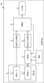
- FIG. 1 is a block diagram illustrating the overall configuration of a deep body thermometer according to an embodiment
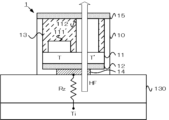
- FIG. It is a sectional view showing an example of composition of a measurement part concerning this embodiment.
- 4 is a flowchart showing details of core body temperature measurement processing according to the present embodiment.
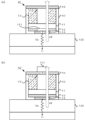
- 8A is a cross-sectional view showing a configuration example of a measurement unit according to Modification 1
- FIG. 8B is a cross-sectional view showing a configuration example of a measurement unit according to Modification 2.
- FIG. FIG. 11 is a block diagram illustrating the overall configuration of a deep body thermometer according to Modification 3
- FIG. 11 is a cross-sectional view showing a configuration example of a measurement unit according to modification 3;
- FIG. 12 is a block diagram illustrating the overall configuration of a deep body thermometer according to Modification 4;
- FIG. 11 is a cross-sectional view showing a configuration example of a measurement unit according to Modification 4;
- 14 is a flowchart showing details of core body temperature measurement processing according to Modification 4.
- FIG. FIG. 12 is a block diagram illustrating the overall configuration of a deep body thermometer according to modification 5;
- FIG. 14 is a cross-sectional view showing a configuration example of a measurement unit according to Modification 5;
- thermometer internal temperature measuring device
- the core body thermometer (internal temperature measuring device) according to the present embodiment is attached to the body surface of the central part such as the head and trunk of the subject to be measured, and from the deep part (inside) such as the brain and organs The heat flow is obtained, and the deep body temperature (internal temperature) is measured.
- the measurement of the internal temperature in the present invention includes not only the measurement of the internal temperature itself, but also the estimation of the internal temperature and the detection of changes in the internal temperature.
- FIG. 1 is a block diagram showing a configuration example of a deep body thermometer according to this embodiment.
- the core thermometer 100 includes a measurement unit 1, a power supply 2, a switching unit 3, a temperature signal processing unit 4, a heat flow signal processing unit 5, a control unit 6, an output unit 7, Equipped with
- FIG. 2 is a cross-sectional view showing a configuration example of the measurement unit according to this embodiment.
- the measurement unit 1 includes a substrate 11 and a thermal diffusion layer 12 on the side of the measuring surface that contacts the body surface of the subject and measures the core body temperature in a resin-made housing 10 . , and a heat insulating layer 13 .
- the measurement unit 1 also includes a heat collecting plate 14 on the surface of the housing 10 on the measurement surface side, and a heat conductive sheet 15 on the opposite surface.
- the substrate 11 is made of, for example, an insulating material such as polyimide, and in this embodiment, is a flexible substrate (film substrate) formed in the shape of a flat plate of 8 mm ⁇ 10 mm.
- the substrate 11 is not limited to a deformable flexible substrate, and may be a non-deformable printed substrate.
- the substrate 11 has a temperature sensor 111 and a thermoelectric element 112 on the surface opposite to the measurement surface. They are arranged close to each other so that they are equal to each other. This point is described in detail in WO2020/184511. The entire specification, claims, and drawings of International Publication No. 2020/184511 are incorporated herein by reference.
- the temperature sensor 111 is composed of, for example, a thermistor such as an NTC (Negative Temperature Coefficient) thermistor whose resistance value changes with temperature.
- the temperature sensor 111 measures the temperature T of the subject's body surface.
- a chip NTC thermistor is used as the temperature sensor 111 because it is preferable that the heat capacity is as small as possible from the viewpoint of improving the responsiveness.
- the temperature sensor 111 is electrically connected to the controller 6 via printed wiring (not shown), and outputs an electric signal (voltage value) indicating the measured temperature T via the printed wiring (not shown).
- the thermoelectric element 112 is composed of, for example, a Peltier element.
- the thermoelectric element 112 functions as a heat flow sensor that obtains the heat flow HF from deep parts such as the brain and organs of the subject.
- the thermoelectric element 112 is electrically connected to the control unit 6 via printed wiring (not shown), and outputs an electric signal (voltage value) indicating the measured heat flow rate HF via the printed wiring (not shown).
- the thermoelectric element 112 flows a direct current, heats or cools the body surface of the subject (changes the temperature of the surface of the object to be measured), and heats from the deep part. It also functions as a heat source to change the flow rate HF.
- the heat diffusion layer 12 is made of a carbon-based thermally conductive sheet such as a graphite sheet or a carbon sheet with extremely high thermal conductivity (for example, 1350 [W/mK], etc.) in order to conduct heat efficiently.
- the thermal diffusion layer 12 may be made of a metal thin film such as an aluminum sheet or copper foil.
- the thermal diffusion layer 12 is provided on the surface of the substrate 11 on the measurement surface side, diffuses the heat entering from the heat collecting plate 14, transfers the heat in the direction parallel to the measurement surface, and spreads the heat on the surface of the substrate 11 on the measurement surface side.
- the thermal diffusion layer 12 can make the temperature T measured by the temperature sensor 111 substantially equal to the temperature T′ of the lower surface (measurement surface side) of the thermoelectric element 112 .
- the temperature sensor 111 can measure the temperature of the subject-side surface (lower surface) of the thermoelectric element 112 .
- the heat insulating layer 13 is made of, for example, an air layer without convection, or a heat insulating material such as polyimide, polyethylene foam, or urethane foam. be filled.
- a heat insulating material such as polyimide, polyethylene foam, or urethane foam.
- the heat collecting plate 14 is made of a metal plate, such as pure copper, which has a higher thermal conductivity than the subject.
- the heat collecting plate 14 collects heat from the subject's body surface and transmits it to the temperature sensor 111 and the thermoelectric element 112 through the heat diffusion layer 12, so that the temperature sensor 111 and the thermoelectric element 112 are each housed in a resin housing. It makes it possible to measure the body surface temperature T and the heat flow HF of the subject through the body 10 .
- the heat-conducting sheet 15 is composed of, for example, a metal thin film such as an aluminum sheet or copper foil having good heat conductivity (for example, 3 to 4 [W/mK]).
- the measurement unit 1 is provided with the heat collecting plate 14 and the heat conductive sheet 15, thereby creating a temperature difference between the surface of the thermoelectric element 112 on the side of the measurement surface and the surface on the opposite side thereof. can promote heat transfer in the direction perpendicular to the
- the power supply 2 shown in FIG. 1 is composed of, for example, a battery such as a general-purpose primary battery or secondary battery, and supplies power (for example, less than 0.5 W) to the thermoelectric element 112 .
- the switching unit 3 is composed of, for example, a general-purpose switching circuit.
- the switching unit 3 switches the operation (mode) of the thermoelectric element 112 under the control of the control unit 6 . Specifically, when the thermoelectric element 112 is used as a heat flow sensor, the switching section 3 electrically connects the thermoelectric element 112 to the heat flow signal processing section 5 . On the other hand, the switching unit 3 electrically connects the thermoelectric element 112 to the power supply 2 when using the thermoelectric element 112 as a heat source.
- the temperature signal processing unit 4 and the heat flow signal processing unit 5 are composed of, for example, a general-purpose amplifier and a general-purpose A/D (Analog-to-digital) converter (ADC).
- the temperature signal processing unit 4 amplifies the analog electric signal input from the temperature sensor 111, converts it into a digital electric signal, and outputs it.
- the heat flow signal processing unit 5 amplifies the analog electric signal input from the thermoelectric element 112, converts it into a digital electric signal, and outputs it.
- the control unit 6 is composed of, for example, an MCU (Micro Control Unit), a ROM (Read Only Memory), a RAM (Random Access Memory), and the like.
- the MCU uses the RAM as a work memory and appropriately executes various programs and the like stored in the ROM to control various operations of the deep body thermometer 100 .
- the control unit 6 controls the subject based on the temperature T indicated by the electrical signal input from the temperature signal processing unit 4 and the heat flow HF indicated by the electrical signal input from the heat flow signal processing unit 5.
- thermoelectric element 112 since the temperature T measured by the temperature sensor 111 and the temperature T' of the lower surface (measurement surface side) of the thermoelectric element 112 are substantially equal, the temperature T indicated by the electrical signal input from the temperature signal processing unit 4 is It is treated as indicating the temperature T′ of the lower surface (measurement surface side) of the thermoelectric element 112 .
- the control unit 6 first outputs a first control signal instructing electrical connection between the thermoelectric element 112 and the heat flow signal processing unit 5 to the switching unit 3 to cause the thermoelectric element 112 to function as a heat flow sensor. .
- the control unit 6 sets the temperature T ( ⁇ T′) indicated by the electrical signal input from the temperature signal processing unit 4 and the heat flow HF indicated by the electrical signal input from the heat flow signal processing unit 5 to the subject. obtained as the temperature T1 and the heat flow HF1 of the subject in the normal state before heating or cooling the body surface of the subject.
- the relationship of the following equation (1) holds between the temperature T1 and the heat flow HF1 obtained in the normal state.
- Ti ⁇ T1)/Rz HF1 (1)
- Ti is the core body temperature
- Rz is the thermal resistance value of the subcutaneous tissue 130 of the subject, both of which are unknown.
- the control unit 6 outputs a second control signal instructing electrical connection between the thermoelectric element 112 and the power source 2 to the switching unit 3 to cause the thermoelectric element 112 to function as a heat source.
- the controller 6 supplies power to the thermoelectric element 112 to change the surface temperature of the subject.
- the control unit 6 sets the temperature T ( ⁇ T ') and the heat flow HF indicated by the electrical signal input from the heat flow signal processing unit 5 are acquired.
- control unit 6 determines whether or not the acquired heat flow rate HF is constant, and if not, acquires the temperature T and the heat flow rate HF again after a predetermined period of time has elapsed.
- the control section 6 determines that the temperature T ( ⁇ T') indicated by the electrical signal input from the temperature signal processing section 4 and the heat flow signal processing section 5 and the heat flow HF indicated by the electrical signal input from are obtained as the subject's temperature T2 and heat flow HF2 in the thermal equilibrium state.
- control unit 6 substitutes the temperature T1 and the heat flow HF1 obtained in the normal state and the temperature T2 and the heat flow HF2 obtained in the thermal equilibrium state into the equation (3) to obtain the subject's core body temperature Ti. demand.
- the control unit 6 displays the determined core body temperature Ti on the screen of the output unit 7 and notifies the subject of the core body temperature Ti.
- control unit 6 may determine whether or not the subject is likely to suffer from heat stroke, based on the transition of the core body temperature. Then, if the core body temperature exceeds a predetermined threshold value (risk value) or if the change in the core body temperature exceeds a predetermined range, the control unit 6 determines that there is a risk of heat stroke. It may be determined and displayed on the screen of the output unit 7, a warning sound may be emitted from a speaker, or an LED may be lit or blinked to warn the subject of the possibility of heat stroke. .
- the output unit 7 is composed of, for example, a general-purpose liquid crystal display.
- the output unit 7 displays the core body temperature Ti obtained by the control unit 6 on the screen.
- the output unit 7 may be composed of a general-purpose non-volatile memory such as a flash memory, for example, and store the core body temperature Ti obtained by the control unit 6 .
- the output unit 7 may be composed of, for example, a general-purpose wireless communication device or the like, and may transmit the core body temperature Ti obtained by the control unit 6 to an external server computer via a network such as the Internet.
- the output unit 7 may be a combination of a general-purpose liquid crystal display, a general-purpose nonvolatile memory, a general-purpose wireless communication device, and the like.
- FIG. 3 is a flowchart showing the details of the core body temperature measurement process according to this embodiment.
- the control unit 6 of the core thermometer 100 first outputs a first control signal to the switching unit 3 to instruct electrical connection between the thermoelectric element 112 and the heat flow signal processing unit 5.
- the thermoelectric element 112 functions as a heat flow sensor (step S301).
- control unit 6 sets the temperature T ( ⁇ T′) indicated by the electrical signal input from the temperature signal processing unit 4 and the heat flow HF indicated by the electrical signal input from the heat flow signal processing unit 5 to the subject. obtained as the temperature T1 and the heat flow HF1 of the subject in the normal state before heating or cooling the body surface of the subject (step S302).
- control unit 6 outputs a second control signal instructing electrical connection between the thermoelectric element 112 and the power source 2 to the switching unit 3 to cause the thermoelectric element 112 to function as a heat source (step S303).
- control unit 6 determines whether a predetermined period of time has passed since the thermoelectric element 112 was made to function as a heat source (step S304), and if it has not passed (step S304; No), loops and waits.
- step S304 when the predetermined period has passed (step S304; Yes), the control unit 6 outputs the first control signal to the switching unit 3 to cause the thermoelectric element 112 to function as a heat flow sensor again (step S305).
- control unit 6 obtains the temperature T ( ⁇ T′) indicated by the electrical signal input from the temperature signal processing unit 4 and the heat flow rate HF indicated by the electrical signal input from the heat flow signal processing unit 5. (step S306).
- control unit 6 determines whether or not the heat flow rate HF acquired in step S306 is constant (step S307), and if not (step S307; No), returns to step S303. After a predetermined period of time has passed, the temperature T and the heat flow rate HF are obtained again.
- step S306 when the heat flow rate HF acquired in step S306 becomes constant (step S307; Yes), the control unit 6 controls the temperature T ( ⁇ T′) indicated by the electrical signal input from the temperature signal processing unit 4, The heat flow HF indicated by the electrical signal input from the heat flow signal processing unit 5 is obtained as the subject's temperature T2 and heat flow HF2 in the thermal equilibrium state (step S308).
- control unit 6 substitutes the temperature T1 and the heat flow HF1 obtained in the normal state and the temperature T2 and the heat flow HF2 obtained in the thermal equilibrium state into the equation (3) to obtain the subject's core body temperature Ti is obtained (measured) (step S309).
- control unit 6 displays the core body temperature Ti obtained in step S309 on the screen of the output unit 7, notifies the subject of the core body temperature Ti (step S310), and then ends the core body temperature measurement process.
- the deep body thermometer (internal temperature measuring device) 100 includes the measurement unit 1 and the control unit 6.
- the measurement unit 1 includes a thermoelectric element 112 that measures the heat flow HF from inside the subject, who is the object to be measured, and a temperature sensor 111 that measures the temperature T of the subject-side surface of the thermoelectric element 112 .
- the measurement unit 1 measures the heat flow HF1 measured by the thermoelectric element 112, the temperature T1 measured by the temperature sensor 111 when the heat flow is HF1, the heat flow HF2 different from the heat flow HF1 measured by the thermoelectric element 112, and the heat flow HF2.
- the temperature T2 measured by the temperature sensor 111 is output when . Based on the heat flow HF1, the temperature T1, the heat flow HF2, and the temperature T2 input from the measurement unit 1, the control unit 6 obtains the core body temperature Ti of the subject.
- the control unit 6 acquires the heat flow HF1 and the temperature T1 from the measurement unit 1.
- the control unit 6 supplies power to the thermoelectric element 112 to change the surface temperature of the subject, and then acquires the heat flow HF2 and the temperature T2 from the measurement unit 1 .
- the control unit 6 determines whether or not the heat flow rate HF input from the measuring unit 1 has become constant.
- the control section 6 acquires the heat flow rate HF and the temperature T input from the measuring section 1 as the heat flow rate HF2 and the temperature T2.
- the control unit 6 obtains the core body temperature Ti of the subject based on the heat flow HF1, the temperature T1, the heat flow HF2, and the temperature T2.
- the core body thermometer 100 can realize substantially the same function as a sandwich-structured heat flux sensor by the temperature sensor 111 and the thermoelectric element 112 without including a sandwich-structured heat flux sensor, which is expensive to manufacture. Therefore, it can be manufactured at a lower cost than before.
- the temperature sensor 111 and the heat flow sensor 112 are arranged close to each other on the surface of the substrate 11 opposite to the measurement surface, but the present invention is not limited to this. do not have. [Modification 1]
- FIG. 4(a) is a cross-sectional view showing a configuration example of a measurement unit according to Modification 1.
- FIG. 4(a) is a cross-sectional view showing a configuration example of a measurement unit according to Modification 1.
- the temperature sensor 111 is installed on the lower surface of the thermoelectric element 112 (the surface on the measurement surface side), surface) may be measured.
- FIG. 4(b) is a cross-sectional view showing a configuration example of a measurement unit according to modification 2.
- FIG. 4(b) is a cross-sectional view showing a configuration example of a measurement unit according to modification 2.
- the temperature sensor 111 is installed on the upper surface (surface opposite to the measurement surface) of the thermally conductive sheet 15 above the thermoelectric element 112, as in the measurement unit 42 according to Modification 2 shown in FIG. may
- the measurement unit 1 has been described as including one temperature sensor 111 and one heat flow sensor 112, but the present invention is not limited to this.
- Modification 3 in which the measurement unit includes two temperature sensors and two thermoelectric elements having different thermal resistance values, will be described.
- FIG. 5 is a block diagram illustrating the overall configuration of a deep body thermometer according to Modification 3. As shown in FIG.
- the core body thermometer 500 includes first and second measuring units 51 and 52, first and second temperature signal processing units 53 and 54, and first and second heat flow signal processing units 55 and 56. , a control unit 6 , and an output unit 7 .
- FIG. 6 is a cross-sectional view showing a configuration example of a measurement unit according to Modification 3. As shown in FIG.
- the substrate 11 of the first measurement unit 51 has a first temperature sensor 611 and a first thermoelectric element 621 on the surface opposite to the measurement surface. They are arranged so close to each other that the temperature T1 and the temperature T1' of the lower surface (measurement surface side) of the first thermoelectric element 621 are substantially equal.
- the first temperature sensor 611 is electrically connected to the controller 6 via printed wiring (not shown) and outputs an electrical signal (voltage value) indicating the measured temperature T1 via the printed wiring (not shown).
- the first thermoelectric element 621 is electrically connected to the controller 6 via printed wiring (not shown), and outputs an electric signal (voltage value) indicating the measured heat flow rate HF1 via the printed wiring (not shown).
- the substrate 11 of the second measurement unit 52 has a second temperature sensor 612 and a second thermoelectric element 622 on the surface opposite to the measurement surface, a temperature T2 measured by the second temperature sensor 612 and a second thermoelectric element 622 . They are arranged so close to each other that the temperature T2' of the lower surface (measurement surface side) of the element 622 is substantially equal.
- the second temperature sensor 612 is electrically connected to the controller 6 via printed wiring (not shown) and outputs an electrical signal (voltage value) indicating the measured temperature T2 via the printed wiring (not shown).
- the second thermoelectric element 622 has a thermal resistance value different from that of the first thermoelectric element 621, so the second thermoelectric element 622 is different from the heat flow rate HF1 measured by the first thermoelectric element 621. Different heat flows HF2 are measured.
- the second thermoelectric element 622 is electrically connected to the controller 6 via printed wiring (not shown), and outputs an electric signal (voltage value) indicating the measured heat flow rate HF2 via the printed wiring (not shown).
- the thermal diffusion layer 12 is provided on the surface of the substrate 11 on the measurement surface side, diffuses the heat entering from the heat collecting plate 14, transfers the heat in the direction parallel to the measurement surface, and spreads the heat on the surface of the substrate 11 on the measurement surface side. uniform temperature distribution in the Thereby, the thermal diffusion layer 12 can make the temperature T1 measured by the first temperature sensor 611 substantially equal to the temperature T1' of the lower surface (measurement surface side) of the first thermoelectric element 621 . As a result, the first temperature sensor 611 can measure the temperature of the subject-side surface (lower surface) of the first thermoelectric element 621 .
- the thermal diffusion layer 12 can make the temperature T2 measured by the second temperature sensor 612 substantially equal to the temperature T2' of the lower surface (measurement surface side) of the second thermoelectric element 622 .
- the second temperature sensor 612 can measure the temperature of the subject-side surface (lower surface) of the second thermoelectric element 622 .
- the first temperature signal processing unit 53 shown in FIG. 5 amplifies the analog electric signal input from the first temperature sensor 611, converts it into a digital electric signal, and outputs it.
- the second temperature signal processing unit 54 amplifies the analog electric signal input from the second temperature sensor 612, converts it into a digital electric signal, and outputs it.
- the first heat flow signal processing unit 55 amplifies the analog electric signal input from the first thermoelectric element 621, converts it into a digital electric signal, and outputs it.
- the second heat flow signal processing unit 56 amplifies the analog electric signal input from the second thermoelectric element 622, converts it into a digital electric signal, and outputs it.
- control unit 6 measures the temperature T1 ( ⁇ T1′) and the heat flow HF1 measured by the first measuring unit 51, and the temperature T2 ( ⁇ T2′) and the heat flow HF2 measured by the second measuring unit 52.
- the measuring section includes the first measuring section 51 and the second measuring section 52 .
- the first measurement unit 51 includes a first thermoelectric element 621 and a first temperature sensor 611 that measures the temperature of the subject-side surface of the first thermoelectric element 621 .
- the first measuring unit 51 then outputs the heat flow HF1 measured by the first thermoelectric element 621 and the first temperature T1 measured by the first temperature sensor 611 .
- the second measurement unit 52 includes a second thermoelectric element 622 having a thermal resistance value different from that of the first thermoelectric element 621, and a second temperature sensor 612 that measures the temperature of the subject-side surface of the second thermoelectric element 622. I'm in.
- the measurement unit 52 then outputs the heat flow HF2 measured by the second thermoelectric element 622 and the temperature T2 measured by the second temperature sensor 612 .
- the core body thermometer 500 employs a sandwich structure with the first and second temperature sensors 611 and 612 and the first and second thermoelectric elements 621 and 622 without having a sandwich structure heat flux sensor which is expensive to manufacture. Since it can achieve substantially the same function as the heat flux sensor of , it can be manufactured at a lower cost than the conventional one.
- the first and second temperature sensors 611 and 621 are connected to the lower surfaces of the first and second thermoelectric elements 612 and 622 (on the measurement surface side), respectively. surface).
- the first and second temperature sensors 611 and 621 detect the upper surface of the thermal conductive sheet 15 (measurement surface and opposite side).
- thermoelectric element for measurement that measures the heat flow rate of the subject
- thermoelectric element for heat source that is used as a heat source
- FIG. 7 is a block diagram illustrating the overall configuration of a deep body thermometer according to Modification 4. As shown in FIG.
- the core thermometer 700 includes a measuring section 71 , a power supply 2 , a temperature signal processing section 4 , a heat flow signal processing section 5 , a control section 6 and an output section 7 .
- FIG. 8 is a cross-sectional view showing a configuration example of a measurement unit according to modification 4.
- the substrate 11 of the measurement unit 71 has a temperature sensor 111 and a thermoelectric element 821 for measurement on the surface opposite to the surface to be measured. They are arranged so close to each other that the temperature T′ of the lower surface (measurement surface side) of 821 is approximately the same.
- a substrate 81 is provided on the upper surface of the heat conductive sheet 15 (the surface opposite to the measurement surface).
- the substrate 81 has a heat source thermoelectric element 822 arranged at a position corresponding to the measuring thermoelectric element 821 on the surface opposite to the measurement surface. That is, the measurement unit 71 according to Modification 4 includes two thermoelectric elements having different roles: a measuring thermoelectric element 821 that measures the heat flow of the subject and a heat source thermoelectric element 822 that is used as a heat source.
- the measuring thermoelectric element 821 functions as a heat flow sensor, and obtains the heat flow HF from deep parts such as the subject's brain and organs.
- the measuring thermoelectric element 821 is electrically connected to the control unit 6 via printed wiring (not shown), and outputs an electric signal (voltage value) indicating the measured heat flow rate HF via the printed wiring (not shown).
- the heat source thermoelectric element 822 functions as a heat source, and when power is supplied from the power supply 2, a direct current flows to heat or cool the body surface of the subject (change the temperature of the surface of the object to be measured). change the heat flow HF from the depths.
- the thermal diffusion layer 12 is provided on the surface of the substrate 11 on the measurement surface side, diffuses the heat entering from the heat collecting plate 14, transfers the heat in the direction parallel to the measurement surface, and spreads the heat on the surface of the substrate 11 on the measurement surface side. uniform temperature distribution in the Thereby, the thermal diffusion layer 12 can make the temperature T measured by the temperature sensor 111 substantially equal to the temperature T′ of the lower surface (measurement surface side) of the thermoelectric element 821 for thermal measurement. As a result, the temperature sensor 111 can measure the temperature of the subject-side surface (lower surface) of the measurement thermoelectric element 821 .
- the heat insulating layer 13 is filled in the housing 80 so as to cover the heat source thermoelectric elements 822 .
- a heat conductive sheet 85 is provided on the surface of the housing 10 opposite to the measurement surface.
- the control unit 6 shown in FIG. 7 first turns off the power source 2 to stop the heat source thermoelectric element 822 .
- the control unit 6 sets the temperature T ( ⁇ T′) indicated by the electrical signal input from the temperature signal processing unit 4 and the heat flow HF indicated by the electrical signal input from the heat flow signal processing unit 5 to the subject. obtained as the temperature T1 and the heat flow HF1 of the subject in the normal state before heating or cooling the body surface of the subject.
- control unit 6 turns on the power supply 2 to activate the heat source thermoelectric element 822, and the temperature T indicated by the electrical signal input from the temperature signal processing unit 4 and the temperature T indicated by the electric signal input from the heat flow signal processing unit 5 are input.
- a heat flow rate HF indicated by the electrical signal is acquired. Further, the control unit 6 determines whether or not the acquired heat flow rate HF is constant, and if it is constant, the temperature T ( ⁇ T' ) and the heat flow HF indicated by the electrical signal input from the heat flow signal processing unit 5 are obtained as the subject's temperature T2 and heat flow HF2 in the thermal equilibrium state.
- control unit 6 substitutes the temperature T1 and the heat flow HF1 obtained in the normal state and the temperature T2 and the heat flow HF2 obtained in the thermal equilibrium state into the equation (3) to obtain the subject's core body temperature Ti. Just ask.
- FIG. 9 is a flowchart showing the details of the core body temperature measurement process according to Modification 4.
- the controller 6 of the core body thermometer 700 first turns off the power supply 2 to stop the heat source thermoelectric element 822 (step S901).
- control unit 6 sets the temperature T ( ⁇ T′) indicated by the electrical signal input from the temperature signal processing unit 4 and the heat flow HF indicated by the electrical signal input from the heat flow signal processing unit 5 to the subject. obtained as the temperature T1 and the heat flow HF1 of the subject in the normal state before heating or cooling the body surface of the subject (step S902).
- control unit 6 turns on the power supply 2 to activate the heat source thermoelectric element 822 (step S903), and the temperature T ( ⁇ T′) indicated by the electrical signal input from the temperature signal processing unit 4,
- the heat flow HF indicated by the electrical signal input from the heat flow signal processing unit 5 is obtained (step S904).
- step S905 determines whether or not the heat flow rate HF acquired in step S904 is constant (step S905). If not (step S905; No), the process returns to step S904. Then, the temperature T ( ⁇ T') and the heat flow rate HF are acquired again to determine whether or not the heat flow rate HF is constant.
- step S904 when the heat flow rate HF acquired in step S904 becomes constant (step S905; Yes), the control unit 6 controls the temperature T ( ⁇ T′) indicated by the electrical signal input from the temperature signal processing unit 4, The heat flow HF indicated by the electrical signal input from the heat flow signal processing unit 5 is acquired as the subject's temperature T2 and heat flow HF2 in the thermal equilibrium state (step S906).
- control unit 6 substitutes the temperature T1 and the heat flow HF1 obtained in the normal state and the temperature T2 and the heat flow HF2 obtained in the thermal equilibrium state into the equation (3) to obtain the subject's core body temperature Ti is obtained (measured) (step S907).
- control unit 6 displays the core body temperature Ti obtained in step S907 on the screen of the output unit 7, notifies the subject of the core body temperature Ti (step S908), and then ends the core body temperature measurement process.
- the measurement unit 71 further includes the heat source thermoelectric element 822 that is used as a heat source.
- the control unit 6 acquires the heat flow HF1 measured by the measuring thermoelectric element 821 and the temperature T1 measured by the temperature sensor 111 . Then, the control unit 6 supplies power to the heat source thermoelectric element 822 to change the surface temperature of the subject, and then controls the heat flow HF2 measured by the thermoelectric element 821 and the temperature measured by the temperature sensor 111. Get T2.
- the core body thermometer 1 can achieve substantially the same function as a sandwich-structured heat flux sensor by the temperature sensor 111 and the thermoelectric element 112 without including a sandwich-structured heat flux sensor, which is expensive to manufacture. Therefore, it can be manufactured at a lower cost than before.
- the temperature sensor 111 may be installed on the lower surface (the surface on the measurement surface side) of the thermoelectric element 821 for measurement, like the measurement unit 41 according to the first modification. Moreover, like the measurement unit 42 according to the second modification, the temperature sensor 111 may be installed on the upper surface (the surface opposite to the measurement surface) of the thermally conductive sheet 85 above the thermoelectric elements 821 for measurement.
- FIG. 10 is a block diagram illustrating the overall configuration of a deep body thermometer according to Modification 5. As shown in FIG. 10
- the core body thermometer 1000 includes a measurement unit 101, a power source 2, a switching unit 3, first and second temperature signal processing units 53 and 54, a heat flow signal processing unit 5, a control unit 6 , and an output unit 7 .
- FIG. 11 is a cross-sectional view showing a configuration example of a measurement unit according to Modification 5. As shown in FIG. 11
- the substrate 11 of the measurement unit 101 has a second temperature sensor 612, a first temperature sensor 611, and a thermoelectric element 112 arranged at approximately equal intervals on the surface opposite to the measurement surface.
- the temperature T′′ measured by the temperature sensor 612, the temperature T measured by the first temperature sensor 611, and the temperature T′ of the lower surface (measurement surface side) of the thermoelectric element 112 are arranged close enough to each other.
- the first temperature sensor 611 is electrically connected to the control unit 6 via printed wiring (not shown), and outputs an electrical signal (voltage value) indicating the measured temperature T via the printed wiring (not shown).
- the second temperature sensor 612 is electrically connected to the controller 6 via printed wiring (not shown), and outputs an electrical signal (voltage value) indicating the measured temperature T′′ via the printed wiring (not shown).
- the thermal diffusion layer 12 diffuses the heat entering from the heat collecting plate 14 and transfers the heat in a direction parallel to the measurement surface, thereby making the temperature distribution in the surface of the substrate 11 on the measurement surface side uniform.
- the thermal diffusion layer 12 has a temperature T′′ measured by the second temperature sensor 612, a temperature T measured by the first temperature sensor 611, a temperature T′ of the lower surface (measurement surface side) of the thermoelectric element 112,
- the first and second temperature sensors 611 and 612 can measure the temperature of the subject-side surface (lower surface) of the thermoelectric element 112 .
- the first temperature signal processing unit 53 shown in FIG. 10 amplifies the analog electric signal input from the first temperature sensor 611, converts it into a digital electric signal, and outputs it.
- the second temperature signal processing unit 54 amplifies the analog electric signal input from the second temperature sensor 612, converts it into a digital electric signal, and outputs it.
- the control unit 6 determines whether or not the temperature T indicated by the electrical signal input from the first temperature signal processing unit 53 is substantially equal to the temperature T′′ indicated by the electrical signal input from the second temperature signal processing unit 54. When the temperature T is approximately equal to the temperature T′′, the control unit 6 determines that the temperature T (or T′′) of the lower surface (measurement surface side) of the thermoelectric element 112 is also approximately equal to the temperatures T and T′′. ) is obtained as indicating the temperature T′ of the lower surface (measurement surface side) of the thermoelectric element 112 .
- the first temperature sensor 611 measures The difference (TT′′) between the temperature T measured by the second temperature sensor 115 and the temperature T′′ measured by the second temperature sensor 115, the temperature T′ of the lower surface (measurement surface side) of the thermoelectric element 112 and the temperature measured by the first temperature sensor 111
- TT′′ T'-T (4)
- thermoelectric element 112 when the temperature T is not substantially equal to the temperature T'', the temperature T' of the lower surface (measurement surface side) of the thermoelectric element 112 is expressed by the following equation (5).
- T' 2T-T" (5)
- the controller 6 substitutes the temperatures T and T'' into the equation (5) to obtain the temperature T' of the lower surface (measurement surface side) of the thermoelectric element 112. Just do it.
- the temperature sensors include the first temperature sensor 611 and the second temperature sensor 612 .
- the measurement unit 101 arranges the second temperature sensor 612, the first temperature sensor 611, and the thermoelectric element 112 at substantially equal intervals.
- the control unit 6 converts the temperature measured by the first temperature sensor 611 into a thermoelectric element. Obtained as the temperature of the surface of 112 on the side of the subject.
- the control unit 6 controls the temperature measured by the second temperature sensor 612 and the temperature measured by the first temperature sensor 611, and the temperature measured by the first temperature sensor 611, the temperature of the subject-side surface of the thermoelectric element 112 is obtained.
- the core body thermometer 1000 is substantially identical to a sandwich-structured heat flux sensor by using the first and second temperature sensors 611 and 612 and the thermoelectric element 112 without including a sandwich-structured heat flux sensor, which is expensive to manufacture. function can be realized, it can be manufactured at a lower cost than before.
- the deep body thermometer 1000 arranges the second temperature sensor 612, the first temperature sensor 611, and the thermoelectric element 112 at substantially equal intervals, so that the temperature of the lower surface (measurement surface side) of the thermoelectric element 112, and thus the deep body temperature Ti can be determined more accurately.
- the configuration including two temperature sensors and thermoelectric elements arranged at equal intervals can be applied not only to the core thermometer 100 according to this embodiment, but also to the modification 3. and 4 are also applicable to core body thermometers 500 and 700 .
- the subject to be measured is a subject, that is, a human being, but the present invention is not limited to this, and the subject to be measured may be an animal.
- the measurement unit 1 is described as contacting the subject's body surface to measure the core body temperature.
- the present invention is not limited to this, and the core body temperature may be measured without (non-contact) contact with the body surface of the subject.
- the core thermometers 100, 500, 700, and 1000 are described as giving a predetermined warning that there is a risk of heat stroke when the core body temperature of the subject meets a predetermined condition. did.
- the present invention is not limited to this, and even if it warns that there is a risk of mental and physical abnormalities other than heat stroke when the core body temperature of the subject meets a predetermined condition
- any physical and mental abnormalities related to core body temperature may be used, such as hypothermia, quality of sleep, basal body temperature, immunity, stress, and the like.
- the core thermometers 100, 500, 700, and 1000 that measure the core body temperature Ti have been exemplified and explained as the internal temperature measuring device according to the present invention.
- the internal temperature measuring device according to the present invention is not limited to this, and may analyze an electric circuit by sending a pulse signal or an AC signal.
- the measurement of human body composition or the like may be performed using impedance (a resistance value when an AC signal is applied).
- physical property analysis such as measurement of moisture content may be performed by generating a heat pulse.
- the internal temperature measuring device is attached to the body surface of the central part such as the head and trunk of the subject to be measured, and measures the internal body temperature of the deep part such as the brain and organs.
- the core body thermometers 100, 500, 700, and 1000 for measuring the core body temperature Ti have been illustrated and described.
- the internal temperature measuring device according to the present invention is not limited to this, and may be attached to a part other than the trunk to measure (including estimation) body temperature other than the core body temperature Ti.
- the body thermometer according to the present invention may be attached to the extremities such as the arms and ankles of the subject, which are distant from the trunk, and measure (including estimation) the body temperature of the extremities. good.
- the control unit 6 may estimate the core body temperature Ti from the body temperature of the extremities of the subject. Specifically, a plurality of internal body temperatures of extremities and core body temperatures of the examinee may be measured in advance to determine the correlation between the two, and the control unit 6 may store this. Then, the control unit 6 may estimate the core body temperature Ti from the measured body temperature of the extremities of the subject, using the correlation obtained in advance. For example, when a correlation is obtained in which the core body temperature Ti is approximately 5°C higher than the body temperature of the extremity, if the body temperature of the extremity measured is 32°C, a constant of 5°C is added. Then, 37° C. can be estimated as the core body temperature Ti. Then, when a predetermined condition is satisfied, such as when the estimated core body temperature exceeds a predetermined threshold value, the control unit 6 may warn the subject that there is a risk of heat stroke.
- a predetermined condition such as when the estimated core body temperature exceeds a predetermined threshold value
- the program executed by the CPU of the control unit 6 is preliminarily stored in the ROM or the like, but the present invention is not limited to this.
- the program By applying the program to an existing general-purpose computer, the deep body thermometers 100, 500, 700, and 1000 according to the above embodiments may be made to function.
- the method of providing such a program is arbitrary. For example, it may be distributed by storing it in a computer-readable recording medium (flexible disk, CD (Compact Disc)-ROM, DVD (Digital Versatile Disc)-ROM, etc.). Alternatively, the program may be stored in storage on a network such as the Internet and provided by downloading it.
- a computer-readable recording medium flexible disk, CD (Compact Disc)-ROM, DVD (Digital Versatile Disc)-ROM, etc.
- the program may be stored in storage on a network such as the Internet and provided by downloading it.
- the above processing is to be shared between the OS (Operating System) and the application program, or by cooperation between the OS and the application program, only the application program may be stored in the recording medium or storage. It is also possible to superimpose a program on a carrier wave and distribute it via a network. For example, the program may be posted on a bulletin board (BBS: Bulletin Board System) on the network and distributed via the network. Then, the above processing may be performed by starting this program and executing it in the same manner as other application programs under the control of the OS.
- BSS Bulletin Board System
- Reference Signs List 1 41, 42, 71, 101 measurement unit 2 power supply 3 switching unit 4 temperature signal processing unit 5 heat flow signal processing unit 6 control unit 7 output unit 10 housing 11, 81 substrate 12 heat diffusion layer 13 heat insulation layer 14 heat collection plate 15, 85 heat conducting sheet 51 first measuring section 52 second measuring section 53 first temperature signal processing section 54 second temperature signal processing section 55 first heat flow signal processing section 56 second heat flow signal processing section 100, 500, 700, 1000 deep body thermometer (internal temperature measuring device) 111 temperature sensor 112 thermoelectric element 130 subcutaneous tissue 611 first temperature sensor 612 second temperature sensor 621 first thermoelectric element 622 second thermoelectric element 821 thermoelectric element for measurement 822 thermoelectric element for heat source
Landscapes
- Physics & Mathematics (AREA)
- General Physics & Mathematics (AREA)
- Engineering & Computer Science (AREA)
- Health & Medical Sciences (AREA)
- Life Sciences & Earth Sciences (AREA)
- Chemical & Material Sciences (AREA)
- Combustion & Propulsion (AREA)
- Nonlinear Science (AREA)
- Biomedical Technology (AREA)
- Pathology (AREA)
- Biophysics (AREA)
- Heart & Thoracic Surgery (AREA)
- Medical Informatics (AREA)
- Molecular Biology (AREA)
- Surgery (AREA)
- Animal Behavior & Ethology (AREA)
- General Health & Medical Sciences (AREA)
- Public Health (AREA)
- Veterinary Medicine (AREA)
- Measuring And Recording Apparatus For Diagnosis (AREA)
- Measuring Temperature Or Quantity Of Heat (AREA)
Priority Applications (5)
| Application Number | Priority Date | Filing Date | Title |
|---|---|---|---|
| EP22928585.3A EP4483789A4 (en) | 2022-02-22 | 2022-02-22 | INTERNAL TEMPERATURE MEASUREMENT DEVICE, INTERNAL TEMPERATURE MEASUREMENT METHOD AND PROGRAM |
| JP2022530851A JP7122056B1 (ja) | 2022-02-22 | 2022-02-22 | 内部温度測定装置、内部温度測定方法、及びプログラム |
| US18/840,284 US20250164323A1 (en) | 2022-02-22 | 2022-02-22 | Internal temperature measurement device, internal temperature measurement method, and program |
| PCT/JP2022/007428 WO2023162054A1 (ja) | 2022-02-22 | 2022-02-22 | 内部温度測定装置、内部温度測定方法、及びプログラム |
| JP2022123012A JP2023122518A (ja) | 2022-02-22 | 2022-08-01 | 内部温度測定装置、内部温度測定方法、及びプログラム |
Applications Claiming Priority (1)
| Application Number | Priority Date | Filing Date | Title |
|---|---|---|---|
| PCT/JP2022/007428 WO2023162054A1 (ja) | 2022-02-22 | 2022-02-22 | 内部温度測定装置、内部温度測定方法、及びプログラム |
Publications (1)
| Publication Number | Publication Date |
|---|---|
| WO2023162054A1 true WO2023162054A1 (ja) | 2023-08-31 |
Family
ID=82929853
Family Applications (1)
| Application Number | Title | Priority Date | Filing Date |
|---|---|---|---|
| PCT/JP2022/007428 Ceased WO2023162054A1 (ja) | 2022-02-22 | 2022-02-22 | 内部温度測定装置、内部温度測定方法、及びプログラム |
Country Status (4)
| Country | Link |
|---|---|
| US (1) | US20250164323A1 (https=) |
| EP (1) | EP4483789A4 (https=) |
| JP (2) | JP7122056B1 (https=) |
| WO (1) | WO2023162054A1 (https=) |
Cited By (1)
| Publication number | Priority date | Publication date | Assignee | Title |
|---|---|---|---|---|
| WO2025252768A1 (en) * | 2024-06-03 | 2025-12-11 | Melexis Technologies Nv | Wearable electronic device and method of measuring a core temperature |
Citations (5)
| Publication number | Priority date | Publication date | Assignee | Title |
|---|---|---|---|---|
| JP2007212407A (ja) | 2006-02-13 | 2007-08-23 | Kanazawa Univ | 非加熱型深部体温計およびそれを用いた深部体温測定装置 |
| JP2018044804A (ja) * | 2016-09-13 | 2018-03-22 | 株式会社フジクラ | デバイス |
| JP2019516960A (ja) * | 2016-05-18 | 2019-06-20 | コーニンクレッカ フィリップス エヌ ヴェKoninklijke Philips N.V. | 単一熱流束センサ装置 |
| WO2020184511A1 (ja) | 2019-03-14 | 2020-09-17 | Biodata Bank株式会社 | 温度センサユニット及び体内温度計 |
| JP2020176934A (ja) * | 2019-04-19 | 2020-10-29 | 日本電信電話株式会社 | 温度測定装置および温度測定方法 |
Family Cites Families (1)
| Publication number | Priority date | Publication date | Assignee | Title |
|---|---|---|---|---|
| CN102326060B (zh) * | 2009-01-19 | 2015-02-25 | 皇家飞利浦电子股份有限公司 | 零热通量传感器及使用方法 |
-
2022
- 2022-02-22 JP JP2022530851A patent/JP7122056B1/ja active Active
- 2022-02-22 WO PCT/JP2022/007428 patent/WO2023162054A1/ja not_active Ceased
- 2022-02-22 US US18/840,284 patent/US20250164323A1/en active Pending
- 2022-02-22 EP EP22928585.3A patent/EP4483789A4/en active Pending
- 2022-08-01 JP JP2022123012A patent/JP2023122518A/ja active Pending
Patent Citations (5)
| Publication number | Priority date | Publication date | Assignee | Title |
|---|---|---|---|---|
| JP2007212407A (ja) | 2006-02-13 | 2007-08-23 | Kanazawa Univ | 非加熱型深部体温計およびそれを用いた深部体温測定装置 |
| JP2019516960A (ja) * | 2016-05-18 | 2019-06-20 | コーニンクレッカ フィリップス エヌ ヴェKoninklijke Philips N.V. | 単一熱流束センサ装置 |
| JP2018044804A (ja) * | 2016-09-13 | 2018-03-22 | 株式会社フジクラ | デバイス |
| WO2020184511A1 (ja) | 2019-03-14 | 2020-09-17 | Biodata Bank株式会社 | 温度センサユニット及び体内温度計 |
| JP2020176934A (ja) * | 2019-04-19 | 2020-10-29 | 日本電信電話株式会社 | 温度測定装置および温度測定方法 |
Non-Patent Citations (1)
| Title |
|---|
| See also references of EP4483789A4 |
Cited By (1)
| Publication number | Priority date | Publication date | Assignee | Title |
|---|---|---|---|---|
| WO2025252768A1 (en) * | 2024-06-03 | 2025-12-11 | Melexis Technologies Nv | Wearable electronic device and method of measuring a core temperature |
Also Published As
| Publication number | Publication date |
|---|---|
| JPWO2023162054A1 (https=) | 2023-08-31 |
| EP4483789A1 (en) | 2025-01-01 |
| US20250164323A1 (en) | 2025-05-22 |
| JP2023122518A (ja) | 2023-09-01 |
| JP7122056B1 (ja) | 2022-08-19 |
| EP4483789A4 (en) | 2025-12-31 |
Similar Documents
| Publication | Publication Date | Title |
|---|---|---|
| KR102630649B1 (ko) | 비-침습적 열 조사를 위한 장치, 시스템들 및 방법들 | |
| US7059767B2 (en) | Electronic clinical thermometer | |
| US6886978B2 (en) | Electronic clinical thermometer | |
| WO2018180800A1 (ja) | 温度拡散係数計測装置、それを用いた深部体温計、深部体温計測装置、および深部体温計測方法 | |
| CN101031233B (zh) | 医用身体深部温度计 | |
| US20100121217A1 (en) | Device for measuring core temperature | |
| US20170095158A1 (en) | Temperature Sensor Structure | |
| JP4310962B2 (ja) | 電子体温計 | |
| US12196622B2 (en) | Temperature measurement device and temperature measurement method | |
| JP4805773B2 (ja) | 電子温度計 | |
| JP2002048786A (ja) | テストエレメント分析システム | |
| JP2019097819A (ja) | 生体データ測定装置 | |
| US8322921B2 (en) | Detection device and process for detecting a temperature of an object | |
| US9797780B2 (en) | Contact type internal thermometer | |
| EP3304016A1 (en) | Fixing element with a built-in temperature sensor | |
| JP5821449B2 (ja) | 温度測定システム及び温度算出方法 | |
| JP2009080000A (ja) | 体温計 | |
| JP7122056B1 (ja) | 内部温度測定装置、内部温度測定方法、及びプログラム | |
| JP6755034B1 (ja) | 温度センサユニット及び体内温度計 | |
| JP5971394B2 (ja) | 温度測定システム及び温度算出方法 | |
| JP2023530683A5 (https=) | ||
| JP7351416B2 (ja) | 設置状態判定方法、および設置状態判定システム | |
| TWM310332U (en) | Standard temperature calibration device for ear thermometer | |
| 장동욱 et al. | Development of Hardware for the Architecture of A Remote Vital Sign Monitor |
Legal Events
| Date | Code | Title | Description |
|---|---|---|---|
| WWE | Wipo information: entry into national phase |
Ref document number: 2022530851 Country of ref document: JP |
|
| 121 | Ep: the epo has been informed by wipo that ep was designated in this application |
Ref document number: 22928585 Country of ref document: EP Kind code of ref document: A1 |
|
| WWE | Wipo information: entry into national phase |
Ref document number: 18840284 Country of ref document: US |
|
| WWE | Wipo information: entry into national phase |
Ref document number: 2022928585 Country of ref document: EP |
|
| NENP | Non-entry into the national phase |
Ref country code: DE |
|
| ENP | Entry into the national phase |
Ref document number: 2022928585 Country of ref document: EP Effective date: 20240923 |
|
| WWP | Wipo information: published in national office |
Ref document number: 18840284 Country of ref document: US |