WO2023157947A1 - Stratifié optique, lentille optique, dispositif d'affichage de réalité virtuelle, film anisotrope optique, corps façonné, polariseur circulaire réfléchissant, polariseur circulaire réfléchissant non plan, corps optique stratifié et lentille composite - Google Patents
Stratifié optique, lentille optique, dispositif d'affichage de réalité virtuelle, film anisotrope optique, corps façonné, polariseur circulaire réfléchissant, polariseur circulaire réfléchissant non plan, corps optique stratifié et lentille composite Download PDFInfo
- Publication number
- WO2023157947A1 WO2023157947A1 PCT/JP2023/005734 JP2023005734W WO2023157947A1 WO 2023157947 A1 WO2023157947 A1 WO 2023157947A1 JP 2023005734 W JP2023005734 W JP 2023005734W WO 2023157947 A1 WO2023157947 A1 WO 2023157947A1
- Authority
- WO
- WIPO (PCT)
- Prior art keywords
- layer
- liquid crystal
- optically anisotropic
- light
- optical
- Prior art date
Links
Images


Classifications
-
- G—PHYSICS
- G02—OPTICS
- G02B—OPTICAL ELEMENTS, SYSTEMS OR APPARATUS
- G02B13/00—Optical objectives specially designed for the purposes specified below
-
- G—PHYSICS
- G02—OPTICS
- G02B—OPTICAL ELEMENTS, SYSTEMS OR APPARATUS
- G02B27/00—Optical systems or apparatus not provided for by any of the groups G02B1/00 - G02B26/00, G02B30/00
- G02B27/02—Viewing or reading apparatus
-
- G—PHYSICS
- G02—OPTICS
- G02B—OPTICAL ELEMENTS, SYSTEMS OR APPARATUS
- G02B3/00—Simple or compound lenses
-
- G—PHYSICS
- G02—OPTICS
- G02B—OPTICAL ELEMENTS, SYSTEMS OR APPARATUS
- G02B5/00—Optical elements other than lenses
- G02B5/30—Polarising elements
-
- G—PHYSICS
- G02—OPTICS
- G02F—OPTICAL DEVICES OR ARRANGEMENTS FOR THE CONTROL OF LIGHT BY MODIFICATION OF THE OPTICAL PROPERTIES OF THE MEDIA OF THE ELEMENTS INVOLVED THEREIN; NON-LINEAR OPTICS; FREQUENCY-CHANGING OF LIGHT; OPTICAL LOGIC ELEMENTS; OPTICAL ANALOGUE/DIGITAL CONVERTERS
- G02F1/00—Devices or arrangements for the control of the intensity, colour, phase, polarisation or direction of light arriving from an independent light source, e.g. switching, gating or modulating; Non-linear optics
- G02F1/01—Devices or arrangements for the control of the intensity, colour, phase, polarisation or direction of light arriving from an independent light source, e.g. switching, gating or modulating; Non-linear optics for the control of the intensity, phase, polarisation or colour
- G02F1/13—Devices or arrangements for the control of the intensity, colour, phase, polarisation or direction of light arriving from an independent light source, e.g. switching, gating or modulating; Non-linear optics for the control of the intensity, phase, polarisation or colour based on liquid crystals, e.g. single liquid crystal display cells
- G02F1/133—Constructional arrangements; Operation of liquid crystal cells; Circuit arrangements
- G02F1/1333—Constructional arrangements; Manufacturing methods
- G02F1/1335—Structural association of cells with optical devices, e.g. polarisers or reflectors
- G02F1/13363—Birefringent elements, e.g. for optical compensation
-
- G—PHYSICS
- G09—EDUCATION; CRYPTOGRAPHY; DISPLAY; ADVERTISING; SEALS
- G09F—DISPLAYING; ADVERTISING; SIGNS; LABELS OR NAME-PLATES; SEALS
- G09F9/00—Indicating arrangements for variable information in which the information is built-up on a support by selection or combination of individual elements
Definitions
- the present invention provides an optical laminate, an optical lens including this optical laminate, a virtual reality display device including this optical lens, an optically anisotropic film, a molded article, a reflective circular polarizer, a non-planar reflective circular polarizer, and laminated optics. Relating to bodies and complex lenses.
- a virtual reality display device is a display device that allows a user to wear a dedicated headset on his or her head and view images displayed through a lens, thereby providing a sense of realism as if one were in a virtual world.
- a virtual reality display device generally has an image display device and a Fresnel lens, but the distance from the image display device to the Fresnel lens is long, which makes the headset thicker and less comfortable to wear. Therefore, as described in Patent Document 1, an image display device, a reflective polarizer, a half mirror, a retardation layer, etc. are provided, and light emitted from the image display device is transmitted between the reflective polarizer and the half mirror.
- a lens configuration called a pancake lens has been proposed, in which the thickness of the entire headset is reduced by reciprocating with .
- a reflective polarizer is a polarizer that has the function of reflecting one polarized light of incident light and transmitting the other polarized light.
- the reflected light and the transmitted light by the reflective polarizer have polarization states orthogonal to each other.
- the mutually orthogonal polarization states are polarization states located at the antipodal points of each other on the Poincare sphere. correspond to
- a reflective linear polarizer in which transmitted light and reflected light are linearly polarized for example, a film obtained by stretching a dielectric multilayer film and a wire grid polarizer are known.
- a reflective circular polarizer in which transmitted light and reflected light are circularly polarized for example, a film having a light reflecting layer in which a cholesteric liquid crystal phase is fixed is known.
- Patent Document 1 discloses a composite lens having a pancake lens configuration, which uses a reflective linear polarizer as the reflective polarizer and includes an image display panel, a reflective linear polarizer, and a half mirror in this order. ing.
- the reflective polarizer must act as a concave mirror with respect to light rays incident from the half mirror side.
- a configuration has been proposed in which the reflective linear polarizer is formed into a curved shape.
- Patent Document 2 discloses a composite lens having a pancake lens configuration that uses a reflective linear polarizer as a reflective polarizer and includes an image display panel, a half mirror, and a reflective linear polarizer in this order. It is Japanese Patent Application Laid-Open No. 2002-200000 proposes a configuration in which both a half mirror and a reflective polarizer are curved in order to improve curvature of field. At this time, the reflective polarizer must act as a convex mirror.
- an optically anisotropic layer such as a retardation layer is formed on the spherical or aspherical curved surface of an optical lens.
- Lamination of an optical laminate having an optical layer, a half mirror and the like is disclosed.
- the optically anisotropic layer is stretched during molding into the curved surface, the optically anisotropic layer develops a retardation, or the retardation of the optically anisotropic layer changes.
- the optical layered body is stretched at a different draw ratio depending on the location, and there is also a problem that the amount of retardation, the amount of change, etc. differs depending on the location.
- the optically anisotropic layer is a retardation layer such as a ⁇ /4 retardation layer
- the retardation of the optically anisotropic layer may become unintended due to undesirable development of retardation.
- the optical axis of the retardation layer may change to an unintended orientation.
- the optically anisotropic layer is a layer such as a cholesteric liquid crystal layer that normally does not have a retardation
- the stretching of the optically anisotropic layer may cause an unnecessary retardation.
- the cholesteric liquid crystal layer develops a retardation, there may be a problem such that the reflected polarized light becomes elliptical polarized light instead of the intended circular polarized light.
- such unfavorable occurrence of phase difference and change in phase difference disturb the polarization of light emitted from the image display device in the pancake lens, thereby disturbing the light. It was found that part of the light did not reciprocate between the reflective polarizer and the half mirror, resulting in leaked light, leading to double images and a decrease in contrast.
- the first embodiment of the present invention has been made in view of the above problems.
- An optical layered body capable of canceling changes in phase difference and the like to reduce leakage light when applied to, for example, a pancake lens type virtual reality display device, an optical lens having the optical layered body, and It is to provide a virtual reality display device using this optical lens.
- Patent Document 1 in order to obtain a wide field of view, low chromatic aberration, low distortion, excellent MTF (modulation transfer function), etc., an optically anisotropic film is pasted on the spherical or aspherical curved surface of an optical lens.
- a method for matching is disclosed. According to studies by the present inventors, in order to laminate an optically anisotropic film containing an optically anisotropic layer on a curved surface, it is necessary to form the optically anisotropic film into a three-dimensional shape. By stretching the optically anisotropic layer, the orientation of the optical axis of the optically anisotropic layer changes.
- the pancake lens disturbs the polarization of the light beam emitted from the image display device, thereby causing part of the light beam to reciprocate between the reflective polarizer and the half mirror. It has been found that if the polarizer does not absorb a portion of the light that should originally be absorbed by the polarizer, light leakage occurs, leading to double images and a decrease in contrast. Further, when an optically anisotropic film is formed on a curved surface, the optically anisotropic layer is stretched at a different draw ratio depending on the location, and the orientation of the optical axis varies depending on the location. It has been found that the optical axis is changed in an unfavorable direction in at least a part of the region, causing light leakage in the pancake lens, leading to double images, deterioration of contrast, and the like.
- An object of the present invention is to provide an optically anisotropic film capable of reducing leakage light when applied to a display device, and a molded article using the optically anisotropic film.
- the optically anisotropic layer is stretched to reduce the thickness of the optically anisotropic layer.
- the orientation of the optical axes such as the reflection axis and the transmission axis changes, and as a result, part of the light rays emitted from the image display device becomes leakage light, and the main image and the ghost image that should be displayed are doubled. found to appear.
- a reflective circular polarizer (hereinafter also referred to as a "reflective circular polarizer”) is applied to a compound lens of a virtual reality display device, the reflective circular polarizer does not have a reflection axis and a transmission axis. It is thought that even if the material is molded or molded, the distortion of the polarization axis is small, and the degree of polarization is unlikely to decrease. However, as a result of investigation by the present inventors, it was found that when the reflective circular polarizer is formed into a curved shape, the color of the main image changes depending on the position within the field of view of the virtual reality display device.
- the reflection band shift occurs due to the difference in the stretching ratio for each orientation depending on the position in the plane of the reflective circular polarizer. It was found that leakage light was generated without being reflected or transmitted.
- the third embodiment of the present invention has been made in view of the above problems.
- An object of the present invention is to provide a reflective circular polarizer capable of suppressing color change of a main image within a field of view and reducing leakage light.
- the problem to be solved by the third embodiment of the present invention is to provide a non-planar reflective circular polarizer, a laminated optical body, a compound lens, and a virtual reality display device.
- a first optically anisotropic layer containing a negative birefringence resin containing a negative birefringence resin
- a third optically anisotropic layer formed by immobilizing a uniformly aligned liquid crystalline compound, and a specific layer selected from the group consisting of a cholesteric liquid crystal layer formed by immobilizing a helically aligned liquid crystalline compound
- An optical laminate having An optical laminate in which the first optically anisotropic layer and the specific layer have curved portions.
- An optical lens comprising a lens substrate having a curved portion, and the optical layered body according to [1] or [2] bonded to the curved portion of the lens substrate.
- a virtual reality display device including an image display device that emits polarized light and the optical lens according to [3].
- Non-linearly oriented including a first optically anisotropic layer having an optic axis, wherein the first optically anisotropic layer has at least the orientation of the optic axis continuously changing in-plane
- An optically anisotropic film having regions.
- the optically anisotropic film of [5] wherein the azimuths of the optical axes in the non-linearly oriented regions are distributed point-symmetrically about at least one point.
- the optically anisotropic film according to [11] is a molded article having a three-dimensional shape including a curved surface, wherein the optical axis of the first optically anisotropic layer and the second optically anisotropic layer are A molded body wherein the polar optic axis makes an angle of 45° in the non-linearly oriented regions described above.
- a reflective circular polarizer having a light reflecting layer formed by fixing a cholesteric liquid crystal phase A reflective circular polarizer, wherein the helical pitch of the cholesteric liquid crystal phase has an in-plane distribution.
- the light reflecting layer has a light reflecting layer obtained by fixing a cholesteric liquid crystal phase containing a rod-like liquid crystal compound and a light reflecting layer obtained by fixing a cholesteric liquid crystal phase containing a discotic liquid crystal compound; Reflective circular polarizer as described.
- the above-described light reflecting layer is formed by alternately arranging a light reflecting layer obtained by fixing a cholesteric liquid crystal phase containing a rod-like liquid crystal compound and a light reflecting layer obtained by fixing a cholesteric liquid crystal phase containing a discotic liquid crystal compound.
- a laminated optical body comprising the reflective circular polarizer according to any one of [13] to [15], a retardation layer, and an absorbing linear polarizer laminated in this order.
- a compound lens comprising the non-planar reflective circular polarizer according to [16] or [17] and a lens.
- a composite lens comprising a non-planar laminated optical body obtained by molding the laminated optical body according to [18], and a lens.
- a virtual reality display device comprising the compound lens according to [19].
- a virtual reality display device comprising the compound lens according to [20].
- the first embodiment of the present invention when applied to, for example, a pancake lens type virtual reality display device by canceling the appearance of the phase difference and the change in the phase difference caused by molding into a curved surface Furthermore, it is possible to provide an optical layered body capable of reducing leakage light, an optical lens having this optical layered body, and a virtual reality display device using this optical lens.
- the optically anisotropic film is molded into a three-dimensional shape including curved surfaces, and can reduce leakage light when applied to a pancake lens type virtual reality display device. , and a molded article using the optically anisotropic film can be provided.
- the reflected circularly polarized light when molded into a non-planar shape and applied to a virtual reality display device, the reflected circularly polarized light can suppress the color change of the main image in the field of view and reduce the leakage light. can provide children. Further, according to the third embodiment of the present invention, it is possible to provide a non-planar reflective circular polarizer, a laminated optical body, a compound lens, and a virtual reality display device.
- FIG. 1 is an example of a virtual reality display device according to the first embodiment of the present invention.
- FIG. 2 is another example of the virtual reality display device according to the first embodiment of the invention.
- FIG. 3 is another example of the virtual reality display device according to the first embodiment of the invention.
- It is an example of the first optically anisotropic layer of the second embodiment of the present invention.
- It is an example of the second optically anisotropic layer of the second embodiment of the present invention.
- It is an example of an optically anisotropic film and a molded article of the second embodiment of the present invention.
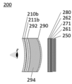
- It is an example of a virtual reality display device using the molded body of the second embodiment of the present invention.
- the term "perpendicular” does not mean that the angle formed by two axes or the like is strictly 90°, but 90° ⁇ 10°, preferably 90° ⁇ 5°. .
- parallel does not mean that the angle formed by two axes or the like is strictly 0°, but 0° ⁇ 10°, preferably 0° ⁇ 5°.
- 45° does not mean that the angle formed by two axes or the like is strictly 45°, but 45° ⁇ 10°, preferably 45° ⁇ 5°.
- “mutually orthogonal polarization states” refer to polarization states located at antipodes to each other on the Poincare sphere.
- Right-handed circularly polarized light) and left-handed circularly polarized light (left-handed circularly polarized light) correspond to this, as described above.
- the "absorption axis” means the polarization direction in which the absorbance is maximized in the plane when linearly polarized light is incident.
- the “reflection axis” means the polarization direction in which the reflectance is maximized in the plane when linearly polarized light is incident.
- the “transmission axis” means a direction perpendicular to the absorption axis or the reflection axis in the plane.
- the “slow axis” means the direction in which the refractive index is maximized in the plane.
- the retardation means in-plane retardation and is described as Re( ⁇ ) unless otherwise specified.
- Re( ⁇ ) represents the in-plane retardation at the wavelength ⁇
- the wavelength ⁇ is 550 nm unless otherwise specified.
- the retardation in the thickness direction at the wavelength ⁇ is described as Rth( ⁇ ) in this specification.
- values measured at wavelength ⁇ using AxoScan OPMF-1 can be used.
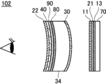
- FIG. 1 conceptually shows an example of a virtual reality display device according to the first embodiment.
- Virtual reality display device 100 shown in FIG. It has a half mirror 30, a lens substrate 34, a first optically anisotropic layer 80 and a third optically anisotropic layer 90, and a reflective polarizer 40, a substrate 36 and an absorbing linear polarizer 22. .
- the first optically anisotropic layer 80 is a layer made of negative birefringence resin.
- the third optically anisotropic layer 90 is a ⁇ /4 retardation layer.
- the reflective polarizer 40 is a reflective linear polarizer.
- the lens substrate 34 is a biconvex lens, and the half mirror 30 is molded into a curved surface (curved surface) on one surface and bonded thereto, and the other surface is provided with the first optically anisotropic layer 80 and the third optically anisotropic layer 80 .
- An optically anisotropic layer 90 is molded into a curved surface (curved surface shape) and bonded.
- the lamination at this time may be performed by a known method such as a method using OCA (Optical Clear Adhesive) or the like. With respect to this point, the same applies to the lamination described below.
- the reflective polarizer 40 and the linear absorptive polarizer 22 are bonded to one surface and the other surface of the flat substrate 36, respectively.
- the substrate 36 is for supporting the reflective polarizer 40 and the absorptive linear polarizer 22, and is preferably made of a material that is transparent to visible light and has a small phase difference, such as glass and an acrylic plate. is made of a material with no phase difference.
- the third optically anisotropic layer 90 ( ⁇ /4 retardation layer) is a specific layer in the first embodiment, and the optical laminate is the first optically anisotropic layer.
- optical layer 80 negative birefringent resin layer
- a third optically anisotropic layer 90 As described above, the optical laminate having the first optically anisotropic layer 80 and the third optically anisotropic layer 90 is formed into a curved surface and bonded to the lens substrate 34, which is a biconvex lens.
- the half mirror 30, the lens substrate 34, the first optically anisotropic layer 80 and the third optically anisotropic layer 90 constitute the optical lens according to the first embodiment.
- the image display panel 70 is, for example, a known image display panel (display panel) such as an organic electroluminescence display panel.
- the image display panel 70 emits an unpolarized image (image light).
- the non-polarized image emitted by the image display panel 70 passes through the ⁇ / 4 retardation layer 13, passes through the absorption linear polarizer 21, becomes linearly polarized light, and is circularly polarized by the ⁇ / 4 retardation layer 11. converted and transmitted through the antireflection layer 50 .
- the linear absorbing polarizer 21 is an absorbing linear polarizer that transmits linearly polarized light perpendicular to the plane of the drawing.
- the ⁇ /4 retardation layer 11 is provided, for example, with the direction of the slow axis aligned so as to convert linearly polarized light perpendicular to the plane of the paper into left-handed circularly polarized light.
- the antireflection layer 50 is a known antireflection layer (AR coat) such as a magnesium fluoride layer and a silicon oxide layer. Moreover, you may bond a well-known antireflection film.
- the left-handed circularly polarized light that has passed through the antireflection layer 50 then enters the half mirror 30 and half of it is transmitted.
- the left-handed circularly polarized light that has passed through the half mirror 30 passes through the lens substrate 34 and the first optically anisotropic layer 80 (negative birefringence resin layer), and passes through the third It is converted into linearly polarized light by the optically anisotropic layer 90 .
- the third optically anisotropic layer 90 which is a ⁇ /4 retardation layer, changes the direction of the slow axis so as to convert left-handed circularly polarized light into linearly polarized light perpendicular to the plane of the paper. be set together.
- the left-handed circularly polarized light reflected by the half mirror 30 is converted into right-handed circularly polarized light by reflection, passes through the antireflection layer 50 , and enters the ⁇ /4 retardation layer 11 .
- the ⁇ /4 retardation layer 11 converts linearly polarized light perpendicular to the plane of the drawing into left-handed circularly polarized light. Therefore, the right-handed circularly polarized light incident on the ⁇ /4 retardation layer 11 is converted into linearly polarized light in the up-down direction on the plane of the drawing, and is incident on the absorptive linear polarizer 21 .
- the absorptive linear polarizer 21 is an absorptive linear polarizer that transmits linearly polarized light perpendicular to the plane of the paper. Therefore, the linearly polarized light in the vertical direction of the paper is absorbed by the absorbing linear polarizer 21 .
- the linearly polarized light perpendicular to the plane of the paper converted from the left-handed circularly polarized light by the third optically anisotropic layer 90 then enters the reflective polarizer 40 .
- the reflective polarizer 40 is a reflective linear polarizer, and as an example, reflects linearly polarized light perpendicular to the plane of the paper and transmits linearly polarized light vertical to the plane of the paper. Therefore, the linearly polarized light perpendicular to the plane of the paper that has entered the reflective polarizer 40 is reflected by the reflective polarizer 40 and enters the third optically anisotropic layer 90 again.
- the third optically anisotropic layer 90 is a ⁇ /4 retardation layer that converts left-handed circularly polarized light into linearly polarized light perpendicular to the plane of the paper. Therefore, the linearly polarized light perpendicular to the plane of the drawing incident on the third optically anisotropic layer 90 is converted into left-handed circularly polarized light by the third optically anisotropic layer 90 .
- the left-handed circularly polarized light converted by the third optically anisotropic layer 90 passes through the lens substrate 34 and enters the half mirror 30 , and half of the light is reflected by the half mirror 30 . This reflection converts left-handed circularly polarized light into right-handed circularly polarized light.
- the right-handed circularly polarized light reflected by the half mirror 30 passes through the lens substrate 34 and the first optically anisotropic layer 80 and enters the third optically anisotropic layer 90 .
- the third optically anisotropic layer 90 is a ⁇ /4 retardation layer that converts left-handed circularly polarized light into linearly polarized light perpendicular to the plane of the paper. Therefore, the right-handed circularly polarized light is converted by the third optically anisotropic layer 90 into linearly polarized light in the up-down direction of the plane of the paper and enters the reflective polarizer 40 .
- the remaining half of the left-handed circularly polarized light that has passed through the half mirror 30 passes through the antireflection layer 50 and enters the ⁇ /4 retardation layer 11 .
- the ⁇ /4 retardation layer 11 converts linearly polarized light perpendicular to the plane of the drawing into left-handed circularly polarized light. Therefore, left-handed circularly polarized light incident on the ⁇ /4 retardation layer 11 is converted into linearly polarized light perpendicular to the plane of the paper. This linearly polarized light perpendicular to the plane of the paper is then incident on the absorbing linear polarizer 21 .
- the absorptive linear polarizer 21 is an absorptive linear polarizer that transmits linearly polarized light perpendicular to the paper surface. Therefore, the linearly polarized light perpendicular to the plane of the paper passes through the absorbing linear polarizer 21 and enters the ⁇ /4 retardation layer 13 .
- the ⁇ /4 retardation layer 13 is provided so as to match the direction of the slow axis so as to convert linearly polarized light perpendicular to the plane of the paper into left-handed circularly polarized light. Therefore, the vertically linearly polarized light incident on the ⁇ /4 retardation layer 13 is converted into left-handed circularly polarized light by the ⁇ /4 retardation layer 13 .
- the left-handed circularly polarized light converted by the ⁇ /4 retardation layer 13 is reflected by the surface of the image display panel 70 and converted into right-handed circularly polarized light, and enters the ⁇ /4 retardation layer 13 again.
- linearly polarized light perpendicular to the paper surface is converted into left-handed circularly polarized light. Therefore, the right-handed circularly polarized light incident on the ⁇ /4 retardation layer 13 is converted into linearly polarized light in the up-down direction on the plane of the drawing, and is incident on the absorptive linear polarizer 21 .
- the absorptive linear polarizer 21 is an absorptive linear polarizer that transmits linearly polarized light perpendicular to the paper surface. Therefore, linearly polarized light in the vertical direction of the paper is absorbed by the absorbing linear polarizer 21 . This also applies to the virtual reality display device 104 shown in FIG. 3, which will be described later.
- the linearly polarized light in the up-down direction of the paper plane reflected by the half mirror 30 and converted by the third optically anisotropic layer 90 then enters the reflective polarizer 40 .
- the reflective polarizer 40 is a reflective linear polarizer that reflects linearly polarized light perpendicular to the plane of the paper and transmits linearly polarized light vertical to the plane of the paper. Therefore, the linearly polarized light incident on the reflective polarizer 40 in the up-down direction of the paper surface is transmitted through the reflective polarizer 40 .
- the linearly polarized light in the vertical direction of the paper that has passed through the reflective polarizer 40 is then transmitted through the absorptive linear polarizer 22 that transmits the linearly polarized light in the vertical direction of the paper, and is displayed on the virtual reality display device 100 as a virtual reality image. Observed by the user.
- the absorptive linear polarizer 22 blocks light that has unnecessarily passed through the reflective polarizer 40 and prevents leakage light (ghost) from being observed by the user of the virtual reality display device 100. It is for That is, when the linearly polarized light in the direction perpendicular to the plane of paper first enters the reflective polarizer 40, it is not reflected by the reflective polarizer 40 and is transmitted through the reflective polarizer 40 unnecessarily. Linear polarization also exists. However, since this linearly polarized light perpendicular to the paper is absorbed by the absorbing linear polarizer 22 that transmits linearly polarized light vertically on the paper, it is possible to prevent leakage light from being observed by the user.
- FIG. 2 conceptually shows another example of the virtual reality display device of the first embodiment.
- Virtual reality display device 102 shown in FIG. It has a substrate 34 , a first optically anisotropic layer 80 , a third optically anisotropic layer 90 , a reflective polarizer 40 and an absorptive linear polarizer 22 .
- the first optically anisotropic layer 80 is a layer made of a negative birefringence resin.
- the third optically anisotropic layer 90 is a ⁇ /4 retardation layer.
- the reflective polarizer 40 is a reflective linear polarizer.
- the antireflection layer 50 is not provided on the surface of the ⁇ /4 retardation layer 11 . However, also in this example, the antireflection layer 50 may be provided on the surface of the ⁇ /4 retardation layer 11 . This also applies to the virtual reality display device 104 shown in FIG. 3, which will be described later.
- the lens substrate 34 is a plate-like member having one convex surface and the other concave surface.
- An anisotropic layer 80, a third optically anisotropic layer 90, a reflective polarizer 40 and an absorptive linear polarizer 22 are laminated, molded into a curved surface, and bonded.
- the lens substrate 34 is made of a material that is transparent to visible light and has a small phase difference, preferably a material that has no phase difference, such as glass or an acrylic plate, similar to the substrate 36 described above. .
- the lens substrate 34 has a convex surface and a concave surface.
- the reflective polarizer 40 and the absorptive linear polarizer 22 are also laminated, shaped into a curved surface, and bonded together. Therefore, the operation of the virtual reality display device 102 shown in FIG. 2 is similar to that of the virtual reality display device 100 shown in FIG.
- the third optically anisotropic layer 90 ( ⁇ /4 retardation layer) is a specific layer in the first embodiment, and the optical laminate is the first optically anisotropic layer. It has an anisotropic layer 80 (a layer made of a negatively birefringent resin) and a third optically anisotropic layer 90 . Further, the half mirror 30, the lens substrate 34, the first optically anisotropic layer 80, the third optically anisotropic layer 90, the reflective polarizer 40, and the absorptive linear polarizer 22 are the same as those of the first embodiment. Construct an optical lens.
- FIG. 3 conceptually shows another example of the virtual reality apparatus of the first embodiment.
- Virtual reality display device 104 shown in FIG. Substrate 34, first optically anisotropic layer 80, reflective polarizer 40A (fourth optically anisotropic layer), third optically anisotropic layer 90 and absorptive linear polarizer 22 .
- the first optically anisotropic layer 80 is a layer made of a negative birefringence resin.
- the third optically anisotropic layer 90 is a ⁇ /4 retardation layer.
- the reflective polarizer 40A is a reflective circular polarizer having a cholesteric liquid crystal layer.
- the lens substrate 34 is the same as the above, and the half mirror 30 is molded into a curved surface on the convex side and bonded, and the concave side is the first optically anisotropic layer 80 and the reflective polarizer.
- the third optically anisotropic layer 90 and the linear absorption polarizer 22 are laminated, shaped into a curved surface, and bonded.
- the reflective polarizer 40A (reflective circular polarizer) and the third optically anisotropic layer 90 ( ⁇ /4 retardation layer) are specific layers in the first embodiment, and the optical laminate is It has a first optically anisotropic layer 80 (negative birefringent resin layer), a reflective polarizer 40A and a third optically anisotropic layer 90 .
- the half mirror 30, the lens substrate 34, the first optically anisotropic layer 80, the reflective polarizer 40A, the third optically anisotropic layer 90, and the absorption linear polarizer 22 are the same as those of the first embodiment. Construct an optical lens.
- the left-handed circularly polarized light converted by the ⁇ /4 retardation layer 11 then enters the half mirror 30 and half of it is transmitted.
- the left-handed circularly polarized light transmitted through the half mirror 30 is transmitted through the lens substrate 34 and the first optically anisotropic layer 80 (negative birefringent resin layer), and is converted into a reflective circular polarizer having a cholesteric liquid crystal layer.
- the reflective polarizer 40A is a reflective circular polarizer that reflects left-handed circularly polarized light and transmits other light. Therefore, left-handed circularly polarized light incident on the reflective polarizer 40A is reflected by the reflective polarizer 40A, passes through the first optically anisotropic layer 80 and the lens substrate 34, and enters the half mirror 30.
- the reflective polarizer 40A is a reflective circular polarizer (cholesteric liquid crystal layer) that reflects left-handed circularly polarized light and transmits other light. Therefore, the right-handed circularly polarized light incident on the reflective polarizer 40A passes through the antireflection layer 40A and enters the third optically anisotropic layer 90.
- FIG. 1 A reflective circular polarizer (cholesteric liquid crystal layer) that reflects left-handed circularly polarized light and transmits other light. Therefore, the right-handed circularly polarized light incident on the reflective polarizer 40A passes through the antireflection layer 40A and enters the third optically anisotropic layer 90.
- the third optically anisotropic layer 90 is a ⁇ /4 retardation layer arranged with the direction of the slow axis aligned so as to convert right-handed circularly polarized light into linearly polarized light in the vertical direction of the paper.
- the absorbing linear polarizer 22 is a linear polarizer arranged with transmission axes aligned so as to transmit linearly polarized light in the vertical direction of the paper surface. Therefore, the right-handed circularly polarized light incident on the third optically anisotropic layer 90 is converted by the third optically anisotropic layer 90 into linearly polarized light in the up-down direction of the plane of the drawing, and then transmitted through the absorbing linear polarizer 22. Then, it is observed by the user of the virtual reality display device 100 as a virtual reality image.
- the absorptive linear polarizer 22 blocks the light that has unnecessarily passed through the reflective polarizer 40A and prevents leakage light (ghost) from being observed by the user of the virtual reality display device 100. be. That is, when the left-handed circularly polarized light first enters the reflective polarizer 40A, some left-handed circularly polarized light is not reflected by the reflective polarizer 40A and is unnecessarily transmitted through the reflective polarizer 40A.
- this left-handed circularly polarized light is converted into linearly polarized light perpendicular to the paper surface by the third optically anisotropic layer 90, which is a ⁇ /4 retardation layer that converts right-handed circularly polarized light into linearly polarized light in the vertical direction of the paper surface. be done. Therefore, this linearly polarized light is absorbed by the absorptive linear polarizer 22, which is a linear polarizer arranged with its transmission axis aligned so that the linearly polarized light in the vertical direction of the paper is transmitted, so that it is used as leakage light. You can prevent people from observing you.
- the first optically anisotropic layer 80 containing a negative birefringent resin and the third optically anisotropic The optical layered body having the optical layer 90 is molded into a curved surface and bonded to the convex surface of the lens substrate 34, which is a convex lens.
- a first optically anisotropic layer 80 containing a negative birefringent resin and a third optically anisotropic layer 90 that is a ⁇ /4 retardation layer. is formed into a curved surface and bonded to the concave surface of the lens substrate 34 .
- the optically anisotropic layer is stretched to develop a retardation in the optically anisotropic layer. Phase difference changes.
- the optical layered body is stretched at a different draw ratio depending on the location, and the amount of retardation, the amount of change, etc., differs depending on the location.
- the optically anisotropic layer is a retardation layer such as a ⁇ /4 retardation layer
- the retardation of the retardation layer may become unintended due to unfavorable development of retardation due to stretching. be. That is, in the virtual reality display device 100 shown in FIG. 1 and the virtual reality display device 102 shown in FIG.
- the retardation of the third optically anisotropic layer 90 may become unintended. If the retardation of the third optically anisotropic layer 90 becomes unintended, the incident left-handed circularly polarized light cannot be converted into proper linearly polarized light, resulting in light including, for example, elliptically polarized light. put away.
- a portion of such light is not reflected by the reflective polarizer 40, which is a reflective linear polarizer, and is transmitted through the reflective polarizer 40 and the absorptive linear polarizer 22, resulting in leakage light (ghost). As a result, it is observed by the user of the virtual reality display device.
- cholesteric liquid crystal layers usually have no retardation.
- the cholesteric liquid crystal layer may exhibit retardation when stretched. That is, in the virtual reality display device 104 shown in FIG. 3, by forming the optical layered body including the reflective polarizer 40A having the cholesteric liquid crystal layer into a curved surface, the reflected circularly polarized light is elliptically polarized or the like. This results in light containing unintended circular polarization. These lights do not properly reciprocate between the reflective polarizer 40 ⁇ /b>A and the half mirror 30 , and part of the light becomes leakage light and is observed by the user of the virtual reality display device 104 .
- the optical laminate of the first embodiment has a first optically anisotropic layer 80 containing a negative birefringence resin.
- a negatively birefringent resin is a resin whose refractive index increases in the direction perpendicular to the stretching direction when stretched.
- the optical laminate of the first embodiment including at least one of the third optically anisotropic layer 90 such as a ⁇ /4 retardation layer and the cholesteric liquid crystal layer is laminated with the lens substrate 34. Therefore, the film is formed into a curved surface and stretched in the bent direction, which changes the phase difference or develops a phase difference that does not exist originally, which causes light leakage.
- the optical layered body of the first embodiment includes a first has an optically anisotropic layer 80 of That is, in the optical layered body of the first embodiment, the first optically anisotropic layer 80 containing a negative birefringent resin is similarly molded into a curved surface together with the ⁇ /4 retardation layer, the cholesteric liquid crystal layer, and the like.
- the refractive index (retardation) of the first optically anisotropic layer 80 ie, the negative birefringent resin
- the change in retardation in the third optically anisotropic layer 90 ( ⁇ /4 retardation layer) caused by stretching is caused by the refractive index in the direction perpendicular to the stretching direction, and by stretching
- the resulting retardation manifestation in the cholesteric liquid crystal layer can be offset. Therefore, according to the optical layered body of the first embodiment, when it is applied to, for example, a pancake lens type virtual reality display device, leakage light can be reduced and a high-quality virtual reality image can be displayed.
- the first optically anisotropic layer, the third optically anisotropic layer, the cholesteric liquid crystal layer (fourth optically anisotropic layer), and the reflective linear polarizer in the optical laminate of the first embodiment are described below. will be described in detail.
- the optical layered body of the first embodiment includes a first optically anisotropic layer containing a negative birefringent resin, and a second layer formed by fixing a uniformly oriented liquid crystalline compound such as a ⁇ /4 retardation layer. 3 optically anisotropic layers, and a specific layer selected from a cholesteric liquid crystal layer (fourth optically anisotropic layer) formed by fixing a helically aligned liquid crystalline compound.
- the optical layered body of the first embodiment may have a second optically anisotropic layer made of a positive birefringent resin.
- the optical laminate of the first embodiment includes the first optically anisotropic layer in addition to the third optically anisotropic layer and the fourth optically anisotropic layer.
- the retardation (refractive index) developed in the first optically anisotropic layer and the change in retardation or development of retardation in the other layers cancel each other out, and the optical laminate as a whole It is possible to suppress the development of the phase difference, the change in the phase difference, and the like.
- the first optically anisotropic layer is made of a negative birefringence resin.
- a negatively birefringent resin is a resin that exhibits negative birefringence when formed into a film. Such resins are also said to have negative intrinsic birefringence.
- the negative birefringence resin is not particularly limited as long as it satisfies the above conditions, but when the film is produced by using the melt extrusion method, it is preferable to use a material with good melt extrusion moldability.
- cyclic olefin-based resins cellulose acylate-based resins, maleimide-based co-resins, polystyrene-based resins, acrylic resins, styrene-based resins such as polystyrenes, polyacrylonitrile-based resins, and polyvinyl acetal-based resins can be used. can be done.
- Cyclic olefin-based resins and cellulose acylate-based resins are positive birefringent resins, that is, when light is incident on a layer formed with molecules uniaxially oriented, the refractive index of the light in the direction of orientation is Excluding resins having a refractive index greater than that of light in the direction perpendicular to the alignment direction.
- the negative birefringent resin used in the first embodiment may contain one resin, or may contain two or more different resins.
- a resin having negative birefringence may be used alone, or two or more may be used in combination when two or more are blended to exhibit negative birefringence. good.
- the negative birefringent resin is a polymer blend consisting of a resin that is solely negative birefringent resin and a resin that is solely positive birefringent resin, the resin that is solely negative birefringent resin.
- the mixing ratio of the resin to the resin which is a positive birefringent resin alone differs depending on the magnitude of the absolute values of the intrinsic birefringence values of both, the birefringence manifestation at the molding temperature, and the like.
- the polymer blend may contain other components in addition to the resin that is a negative birefringent resin alone and the resin that is a positive birefringent resin alone.
- the component is not particularly limited as long as it does not impair the effects of the first embodiment, and can be appropriately selected according to the purpose. Suitable examples include a compatibilizer.
- the compatibilizer can be suitably used when phase separation occurs during blending. It is possible to improve the mixed state with the resin, which is the birefringent resin.
- the negative birefringent resin used in the first embodiment is a polystyrene resin.
- the polystyrene resin refers to resins obtained by polymerizing styrene and styrene derivatives as main components, and copolymer resins of styrene and other resins.
- the polystyrene-based resin that can be used in the first embodiment is not particularly limited as long as it does not impair the effects of the first embodiment, and known polystyrene-based resins and the like can be used.
- copolymer resins of styrene and other resins which can improve birefringence, film strength and heat resistance.
- Copolymer resins include, for example, styrene-acrylonitrile resins, styrene-acrylic resins, styrene-maleic anhydride resins, and multi-component (binary, ternary, etc.) copolymers thereof.
- styrene-acrylonitrile resins styrene-acrylic resins
- styrene-maleic anhydride resins and multi-component (binary, ternary, etc.) copolymers thereof.
- styrene-acrylic resins and styrene-maleic anhydride resins are preferable from the viewpoint of heat resistance and film strength.
- hydrogenation of the styrene-based resin can be preferably used.
- the styrene-maleic anhydride resin include "Daylark D332” manufactured by Nova Chemical Co., Ltd., and the like.
- As the styrene-acrylic resin "Delpet 980N” manufactured by Asahi Kasei Chemical Co., Ltd., which will be described later, can be used.
- the polystyrene-based resin may be an amorphous polystyrene-based resin or a crystalline polystyrene-based resin.
- a crystalline polystyrene-based resin from the viewpoint of mechanical strength, it is preferable to contain a crystalline polystyrene-based resin, while from the viewpoint of facilitating curved surface molding, it is preferable to contain a non-crystalline polystyrene-based resin.
- Crystalline polystyrene resins include polystyrene resins having a syndiotactic structure and polystyrene resins having an isotactic structure. Examples of amorphous polystyrene resins include polystyrene resins having an atactic structure.
- the polystyrene resin may have a syndiotactic structure, an isotactic structure, or an atactic structure, but preferably has a syndiotactic structure.
- a polystyrene-based resin having a syndiotactic structure is particularly excellent in high mechanical strength and low thermal shrinkage.
- the polystyrene resin having a syndiotactic structure used in the first embodiment is a steric resin in which side chains such as phenyl groups and derivatives thereof are alternately positioned in opposite directions with respect to the main chain formed from carbon-carbon bonds.
- the stereoregularity measured by this 13C-NMR method is the abundance ratio of a plurality of consecutive constitutional units, for example, dyads when there are two, triads when there are three, pendad when there are five. can.
- the racemic diad is usually 75 to 100%, preferably 85 to 100%, or the racemic pentahead is 30 to 100%, It preferably has a stereoregularity of 50 to 100%.
- poly(alkylstyrene) includes poly(methylstyrene), poly(ethylstyrene), poly(propylstyrene), poly(butylstyrene), poly(phenylstyrene), poly(vinylnaphthalene), poly(vinylstyrene). ), and poly(acenaphthine).
- Poly(halogenated styrene) includes poly(chlorostyrene), poly(bromostyrene), and poly(fluorostyrene).
- Poly(alkoxystyrene) includes poly(methoxystyrene) and poly(ethoxystyrene). Among these, more preferred are poly(styrene) and poly(methylstyrene), and more preferred is poly(styrene).
- polystyrene resins having a syndiotactic structure may be copolymers other than homopolymers as described above.
- the comonomer component of the copolymer in addition to the monomers constituting the styrene polymer described above, olefin monomers such as ethylene, propylene, butene, hexene and octene, diene monomers such as butadiene and isoprene, and cyclic olefin monomers, Cyclic diene monomers, polar vinyl monomers such as methyl methacrylate, maleic anhydride and acrylonitrile, and the like can be mentioned.
- styrene is the main component, and alkyl styrene, hydrogenated styrene, and halogenated styrene are preferably copolymerized.
- alkyl styrene, hydrogenated styrene, and halogenated styrene are preferably copolymerized.
- p-methylstyrene, m-methylstyrene, p-tert-butylstyrene, p-chlorostyrene, m-chlorostyrene, p-fluorostyrene, or hydrogenated styrene are preferred, and p-methylstyrene is particularly preferred. Styrene.
- the amount of these added is preferably 0 to 30% by mass, more preferably 1 to 20% by mass, and still more preferably 3 to 10% by mass based on the total polymer. Copolymerization of these retards the crystallization rate and suppresses the formation of spherulites. As a result, a polystyrene resin having a syndiotactic structure with high transparency and high folding endurance can be achieved.
- syndiotactic-polystyrene polymer and other polymers may be blended and used.
- preferred polymer blend components are a styrene polymer having a syndiotactic structure and a styrene polymer having an atactic structure as described above.
- polystyrene having a syndiotactic structure is the main component, and p-methylstyrene, m-methylstyrene, p-tert-butylstyrene, p-chlorostyrene, m-chlorostyrene, p-fluoro
- p-methylstyrene, m-methylstyrene, p-tert-butylstyrene, p-chlorostyrene, m-chlorostyrene, p-fluoro A blend of at least one of a homopolymer with a syndiotactic or atactic structure composed of styrene, hydrogenated styrene, etc., and a copolymer with a syndiotactic or atactic structure composed of at least one of these monomers and styrene. preferably.
- Particularly preferred is a blend of p-methylstyrene having a syndiotactic structure and a copolymer of p-methylstyrene having a syndiotactic structure and styrene with polystyrene having a syndiotactic structure.
- the amount of these blended polymers added is preferably 0 to 30% by mass, more preferably 1 to 20% by mass, and still more preferably 3 to 10% by mass of the total amount of the polymers.
- the negative birefringent resin used for the first optically anisotropic layer should have a peak temperature of tan ⁇ (loss tangent (loss factor)) of 170° C. or less from the viewpoint of facilitating molding into a curved shape. is preferred. From the viewpoint of enabling molding at low temperatures, the peak temperature of tan ⁇ is preferably 150° C. or lower, more preferably 130° C. or lower.
- a method for measuring tan ⁇ will be described.
- a dynamic viscoelasticity measuring device (DVA-200, manufactured by IT Keisoku Co., Ltd.)
- a film sample that has been preliminarily conditioned at a temperature of 25 ° C. and a humidity of 60% Rh for 2 hours or more under the following conditions
- Apparatus DVA-200 manufactured by IT Instrument Control Co., Ltd.
- Sample 5 mm, length 50 mm (gap 20 mm) Measurement conditions: Tensile mode Measurement temperature: -150°C to 220°C Temperature rising condition: 5°C/min Frequency: 1Hz Generally, in optical applications, a stretched resin substrate is often used, and the tan ⁇ peak temperature often becomes high due to the stretching treatment.
- a triacetyl cellulose (TAC) substrate for example, TG40 manufactured by Fuji Film Co., Ltd.
- TAC triacetyl cellulose
- Such a first optically anisotropic layer may be used as a support when forming a reflective polarizer, a third optically anisotropic layer, and the like.
- the optical laminate of the first embodiment may have a second optically anisotropic layer.
- the second optically anisotropic layer is made of a positive birefringent resin.
- a positive birefringence resin is a resin that exhibits positive birefringence when formed into a film. Such resins are also said to have positive intrinsic birefringence.
- the second optically anisotropic layer for example, acts as a support when forming the reflective polarizer and the third optically anisotropic layer, etc. After these layers are formed, they are peeled off. good too.
- the positive birefringence resin is not particularly limited, but for example, cellulose acylate, polycarbonate, polysulfone, polyethersulfone, cyclic polyolefin, polyolefin, polyamide, polystyrene, polyester, etc., can be selected from materials having positive birefringence. can be used. Among them, cellulose acylate film, polycarbonate and cyclic polyolefin are preferred.
- the third optically anisotropic layer is a layer in which a uniformly oriented liquid crystalline compound is fixed.
- the third optically anisotropic layer is the specific layer in the first embodiment.
- a layer in which a rod-like liquid crystal compound is uniformly aligned horizontally to the in-plane direction, a layer in which a discotic liquid crystal compound is uniformly aligned perpendicular to the in-plane direction, and the like can be used.
- a retardation layer having reverse dispersion can be produced by uniformly aligning and fixing a rod-shaped liquid crystal compound having reverse dispersion. can.
- the third optically anisotropic layer is exemplified by a ⁇ /4 retardation layer ( ⁇ /4 plate, ⁇ /4 wavelength plate).
- the ⁇ /4 retardation layer used in the first embodiment may be a single-layer type composed of one optically anisotropic layer, or two or more optically anisotropic layers each having a plurality of different slow axes.
- a laminated wave plate configured by laminating layers may also be used.
- Specific examples of the laminated ⁇ / 4 retardation layer include International Publication No. 2013/137464, International Publication No. 2016/158300, Japanese Patent Application Publication No. 2014-209219, Japanese Patent Application Publication No. 2014-209220, International Publication No. Examples include those described in 2014/157079, JP 2019-215416, WO 2016/158300, and WO 2019/160044.
- the fourth optically anisotropic layer is a cholesteric liquid crystal layer formed by fixing a spirally aligned liquid crystalline compound.
- the cholesteric liquid crystal layer is a specific layer in the first embodiment, and is the reflective polarizer 40A (reflective circular polarizer) in the virtual reality display device 104 shown in FIG. 3, as described above.
- a cholesteric liquid crystal layer has a helical structure in which a liquid crystal compound is spirally revolved and stacked.
- As a cycle (helical cycle) a liquid crystal compound that spirals spirally has a structure in which multiple cycles are stacked.
- the cholesteric liquid crystal layer reflects right-handed circularly polarized light or left-handed circularly polarized light in a specific wavelength range and transmits other light, depending on the length of the helical period and the direction of helical rotation (sense) of the liquid crystal compound. do. Therefore, when the virtual reality display device displays a color image, the reflective circular polarizer may include, for example, a cholesteric liquid crystal layer having a central wavelength of selective reflection for red light, a central wavelength for selective reflection of green light, It may have a plurality of cholesteric liquid crystal layers, such as a cholesteric liquid crystal layer having a wavelength and a cholesteric liquid crystal layer having a central wavelength of selective reflection for blue light. In the first embodiment, various known cholesteric liquid crystal layers can be used.
- a reflective linear polarizer may be used instead of the fourth optically anisotropic layer, that is, the cholesteric liquid crystal layer.
- various known reflective linear polarizers can be used.
- the reflective linear polarizer include a film obtained by stretching a layer containing two types of polymers, and a wire grid polarizer, as described in JP-A-2011-053705. From the viewpoint of brightness, a film obtained by stretching a layer containing a polymer is preferable.
- a reflective polarizer (trade name: APF) manufactured by 3M Corporation, a wire grid polarizer (trade name: WGF) manufactured by Asahi Kasei Corporation, and the like can be suitably used.
- a virtual reality display device of the first embodiment includes an image display device that emits at least polarized light, and an optical lens of the first embodiment in which the optical layered body of the first embodiment is bonded to a lens base material.
- the virtual reality display device of the first embodiment may have a ⁇ /4 retardation layer, an absorbing linear polarizer, a half mirror, etc. as described above. It may have additional optical members such as lenses.
- ⁇ /4 retardation layers are available for use in virtual reality display devices.
- the ⁇ /4 retardation layer include a ⁇ /4 retardation layer as a third optically anisotropic layer formed by fixing a uniformly aligned liquid crystal compound, a triacetyl cellulose retardation layer, A polymer carbonate retardation layer, a cycloolefin retardation layer, and the like are exemplified.
- Various types of known linear absorptive polarizers are available, and may be coating polarizers or stretched polarizers. Examples of absorptive linear polarizers include iodine-based polarizers, dye-based polarizers using dichroic dyes, and polyene-based polarizers. Also, an absorbing linear polarizer produced by adsorbing iodine or a dichroic dye to polyvinyl alcohol and stretching the film can be suitably used.
- a known image display device can be used as the image display device.
- display devices such as an organic electroluminescence display device, an LED (Light Emitting Diode) display device, and a micro LED display device, in which self-luminous fine light emitters are arranged on a transparent substrate, are exemplified.
- These self-luminous display devices usually have a (circular) polarizing plate attached to the display surface to prevent reflection on the display surface. Therefore, the emitted light is polarized.
- a liquid crystal display device is exemplified as another image display device. Since the liquid crystal display device also has a polarizing plate on its surface, the emitted light is polarized.
- the image display device is composed of the image display panel 70, the ⁇ /4 retardation layer 13, the absorbing linear polarizer 21 and the ⁇ /4 retardation layer 11. be.
- the image display device may also have an antireflection layer 50, as described above.
- the optically anisotropic film of the second embodiment includes a first optically anisotropic layer having an optic axis, and the first optically anisotropic layer has at least the optic axis orientation continuous in-plane. It has a non-linearly oriented region changing to Moreover, it is preferable that the optically anisotropic film further includes a second optically anisotropic layer that has an optical axis and that the orientation of the optical axis is uniform in the plane.
- a plurality of optically anisotropic layers are generally used in a pancake lens.
- the optically anisotropic film includes both the first optically anisotropic layer and the second optically anisotropic layer and is molded into a three-dimensional shape
- the orientation of the optical axis of the first optically anisotropic layer and the direction of the optical axis of the first optically anisotropic layer It is preferable that the directions of the optical axes of the two optically anisotropic layers change simultaneously.
- the first optically anisotropic layer of the second embodiment has at least the non-linearly oriented region in which the orientation of the optic axis continuously changes within the plane.
- the azimuth of the optical axis changes continuously within the plane means that when short line segments representing the azimuth of the optical axis are drawn at each position within the plane, an envelope connecting these line segments is not a straight line.
- the azimuths of the optical axes are preferably distributed point-symmetrically about at least one point.
- the optical thickness of the first optically anisotropic layer changes continuously in the plane in the non-linearly oriented region.
- the optically anisotropic film is molded into a three-dimensional shape, it is preferable to change the optical thickness in accordance with the different stretch ratios depending on the location so that the optical thickness after molding is uniform in the plane.
- the optical thickness can be changed by adjusting the refractive index, birefringence, optical density, or the like, in addition to adjusting the physical film thickness.
- the optical thickness is the product of the actual film thickness and the birefringence ⁇ n.
- it is obtained by multiplying the actual film thickness by the absorption coefficient.
- the first optically anisotropic layer of the second embodiment may be a retardation layer.
- the retardation layer is preferably a ⁇ /4 plate.
- the 1/4 plate may have a phase difference of approximately 1/4 wavelength in any wavelength in the visible range.
- a retardation plate having a retardation of approximately 138 nm at a wavelength of 550 nm can be preferably used.
- the quarter plate has reverse dispersion with respect to wavelength. .
- having reverse dispersion with respect to wavelength means that the value of the phase difference at the wavelength increases as the wavelength increases.
- the first optically anisotropic layer When the first optically anisotropic layer is a retardation layer, its slow axis is the optical axis in the second embodiment. That is, when the first optically anisotropic layer is a retardation layer, the first optically anisotropic layer has at least a non-linear orientation in which the orientation of the slow axis changes continuously within the plane. have an area.
- the "non-linearly oriented region in which the orientation of the optic axis (slow axis) changes continuously within the plane” The operation of measuring the thickness measurement range and finding the direction of the slow axis in that range is performed multiple times along one direction in the plane, and the direction of the slow axis observed in each measurement range is continuous.
- a region in which the direction of the optical axis (slow axis) changes continuously is referred to as a “non-linearly oriented region in which the orientation of the optic axis (slow axis) changes continuously within the plane”. That is, when the direction of the slow axis of two continuous measurement ranges along one in-plane direction is different, the area including these two measurement ranges is the "non-linearly oriented area”.
- the continuous measurement ranges are not limited to being in contact with each other, they may be spaced apart, and may overlap if the ranges are deviated.
- the size of one measurement range is preferably ⁇ 0.1 to 2 mm, more preferably ⁇ 0.1 to 1 mm.
- interval between continuous measurement ranges is preferably 1 to 10 mm, more preferably 1 to 2 mm.
- the direction of the optical axis changes continuously within the plane
- the direction of the optical axis in each measurement range rotates clockwise or counterclockwise along one direction within the plane. It means that the direction of rotation is changing in either direction.
- the optical axis rotates in one in-plane direction such that the angle formed by the optical axes in continuous measurement ranges becomes smaller.
- the "non-linearly oriented region" will be further described with reference to the diagram of the first optically anisotropic layer 210a shown in FIG. 4, which will be described later.
- the orientation of the optical axis of the first optically anisotropic layer 210a shown in FIG. corresponding to the in-plane position of the measurement range.
- the first optically anisotropic layer 210a shown in FIG. 4 is, for example, laminated along the curved surface of a rotationally symmetrical convex lens or concave lens. Therefore, as will be described later, the first optically anisotropic layer 210a shown in FIG. 4 is formed in a substantially spherical crown shape. Therefore, the region where the first optically anisotropic layer 210a is formed has a substantially circular shape.
- the slow axes of the three measurement ranges on the upper side of the figure rotate clockwise (rightward) from top to bottom. It can be said that the Also, the slow axis in the third measurement range from the top to the slow axis in the sixth measurement range are parallel and not rotated. Furthermore, it can be said that the slow axis of the sixth measurement range from the top to the slow axis of the ninth measurement range rotate counterclockwise (counterclockwise) from top to bottom. .
- the region connecting the first measurement range to the third measurement range from the top in the vertical direction passing through the center is the second measurement range. It corresponds to the "non-linearly oriented area" in the form, and the area connecting the sixth to ninth measuring range from the top corresponds to the "non-linearly oriented area" in the second embodiment.
- Each of the upper non-linearly oriented region and the lower non-linearly oriented region changes along one direction in one direction of rotation.
- the first optically anisotropic layer has such "non-linearly oriented regions".
- the azimuths of the optical axis (slow axis) in each measurement range are distributed point-symmetrically with respect to the center.
- the first optically anisotropic layer changes the orientation (angle) of the optic axis in each measurement range along one in-plane direction, that is, the optic axes of continuous measurement ranges
- the total value of the changed angles is preferably 0 to 10°, more preferably 0 to 5°, and even more preferably 0 to 3°.
- the change in the angle of the optical axis in the continuous measurement range is integrated with the clockwise rotation being positive and the counterclockwise rotation being negative.
- the distribution of the orientation of the optic axis in the first optically anisotropic layer depends on the shape of the first optically anisotropic layer (the radius of curvature of the curved surface, etc.), the shape of other layers to be laminated ( For example, it may be appropriately set according to the second optically anisotropic layer described later) and the like.
- the shape of the molding region in the first optically anisotropic layer may also be appropriately set to a circular shape, an elliptical shape, an irregular shape, or the like according to the shape in which the first optically anisotropic layer is to be molded.
- the first optically anisotropic layer 210a when the first optically anisotropic layer 210a is formed in a substantially spherical crown shape, the closer the region is to the edge, the greater the stretch ratio in the diametrical direction and the circumferential direction. , the stretching rate in the vertical direction and the horizontal direction in the figure differ depending on the position. Therefore, the closer the region is to the peripheral portion, the greater the change in the direction of the optical axis upon molding. Therefore, when the first optically anisotropic layer 210a is formed in a substantially spherical crown shape, the first optically anisotropic layer 210a has a marginal portion to compensate for this change in the direction of the optical axis. It is sufficient to have a non-linearly oriented region in a region close to .
- the first optically anisotropic layer of the second embodiment may be a polarizer layer.
- the polarizer layer preferably contains at least a matrix compound and a dichroic substance, and the degree of orientation of the dichroic substance is 0.95 or more.
- the degree of orientation of the dichroic substance is more preferably 0.97 or more, and the higher the degree of orientation, the more effectively stray light, ghosts, etc. can be suppressed.
- the first optically anisotropic layer When the first optically anisotropic layer is a polarizer layer, its absorption axis is the optical axis in the second embodiment. That is, when the first optically anisotropic layer is a polarizer layer, the first optically anisotropic layer has at least a non-linearly oriented region in which the orientation of the absorption axis changes continuously within the plane.
- the first optically anisotropic layer is a polarizer layer, it has the same configuration as the retardation layer described above, except that the slow axis is read as the absorption axis.
- the orientation of the absorption axis in each measurement range can be obtained with AxoScan.
- the first optically anisotropic layer of the second embodiment is a layer formed by fixing a liquid crystalline compound. Since liquid crystalline compounds can be easily oriented in any direction by photo-alignment or the like, it is also easy to continuously change the orientation of the optic axis within the plane, making it suitable for producing non-linearly oriented regions. ing. Further, after the liquid crystalline compound is oriented, the alignment direction of the liquid crystalline compound can be fixed by fixing by photopolymerization or the like.
- the first optically anisotropic layer is a retardation layer, for example, referring to JP-A-2020-084070, a rod-shaped liquid crystal compound having reverse dispersion is uniformly oriented and fixed.
- the polarizer layer can be produced by orienting and fixing a mixture containing a liquid crystalline compound and a dichroic substance. . That is, the liquid crystalline compound corresponds to the matrix compound described above.
- the second optically anisotropic layer is characterized by uniformly oriented optical axes.
- the second optically anisotropic layer is not particularly limited. It may be a layer produced by stretching. Alternatively, it may be a layer in which a uniformly oriented liquid crystalline compound is fixed.
- the second optically anisotropic layer may be a retardation layer or a polarizer layer, and can be appropriately selected depending on the required function, purpose of use, and the like.
- the optically anisotropic film of the second embodiment is a laminate prepared by directly coating one of the first optically anisotropic layer and the second optically anisotropic layer on the other.
- it may be a laminate produced by separately producing the first optically anisotropic layer and the second optically anisotropic layer and then laminating them together.
- the optically anisotropic film of the second embodiment may additionally contain a substrate and the like.
- the base material is not particularly limited, it is preferable that the peak temperature of tan ⁇ (loss tangent (loss factor)) is 170° C. or less from the viewpoint of facilitating molding into a three-dimensional shape. From the viewpoint of enabling molding at low temperatures, the peak temperature of tan ⁇ is preferably 150° C. or lower, more preferably 130° C. or lower.
- Base materials having a tan ⁇ peak temperature of 170° C. or less include, for example, polyacrylates, polymethacrylates, cyclic polyolefins, and polyolefins.
- a method for measuring tan ⁇ will be described.
- a dynamic viscoelasticity measuring device (DVA-200, manufactured by IT Keisoku Co., Ltd.)
- a film sample that has been preliminarily conditioned at a temperature of 25 ° C. and a humidity of 60% Rh for 2 hours or more under the following conditions
- Apparatus DVA-200 manufactured by IT Instrument Control Co., Ltd.
- Sample 5 mm, length 50 mm (gap 20 mm) Measurement conditions: Tensile mode Measurement temperature: -150°C to 220°C Temperature rising condition: 5°C/min Frequency: 1Hz Generally, in optical applications, a stretched resin substrate is often used, and the tan ⁇ peak temperature often becomes high due to the stretching treatment.
- a triacetyl cellulose (TAC) substrate for example, TG40 manufactured by Fuji Film Co., Ltd.
- TAC triacetyl cellulose
- the molded article of the second embodiment is an optically anisotropic film including a first optically anisotropic layer and a second optically anisotropic layer molded into a three-dimensional shape including a curved surface,
- the optic axis of the first optically anisotropic layer and the optic axis of the second optically anisotropic layer form an angle of 45° in the non-linearly oriented regions of the first optically anisotropic layer.
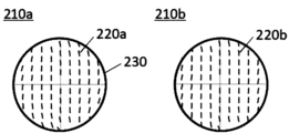
- FIG. 4 shows an example of a change in distribution of optic axis orientations in the non-linearly oriented regions of the first optically anisotropic layer.
- Reference numeral 210a is the first optically anisotropic layer before the optically anisotropic film is formed into a three-dimensional shape.
- the azimuths 220a of the optical axes are distributed point-symmetrically with the center of the non-linearly oriented region 230 as the center.
- the first optically anisotropic layer 210b is partially stretched at different stretch ratios, thereby changing the orientation of the optical axis, as indicated by reference numeral 220b. distribution.
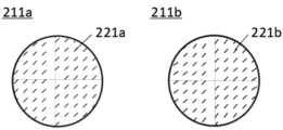
- FIG. 5 shows changes in the distribution of the orientations of the optical axes of the second optically anisotropic layer.
- Reference numeral 211a denotes a second optically anisotropic layer before the optically anisotropic film is formed into a three-dimensional shape.
- the azimuth 221a of the optical axis is uniformly oriented.
- the second optically anisotropic layer 211b after the optically anisotropic film has been formed into a three-dimensional shape is partially stretched at different stretch ratios, thereby changing the orientation of the optical axis, and the reference numeral 221b It becomes a non-uniform distribution like FIG. 6 shows changes in the distribution of the optical axes in the optically anisotropic film containing the first optically anisotropic layer and the second optically anisotropic layer.
- Reference numeral 240a denotes an optically anisotropic film before the optically anisotropic film is formed into a three-dimensional shape.
- the angles between the optical axes of the respective optically anisotropic layers differ depending on the location.
- the orientation of each optic axis has changed due to molding, and as a result, the angle between each optic axis in the non-linearly oriented region 230 is It is 45° regardless of location.
- thermoforming or vacuum forming can be used as a method for forming the optically anisotropic film into a three-dimensional shape. Specifically, insert molding as described in JP-A-2004-322501, WO2010/1867, and vacuum molding and injection molding as described in JP-A-2012-116094. , air pressure molding, vacuum coating molding, in-mold transfer, mold press, and the like. It is also preferable to heat during molding, preferably from 80°C to 170°C, more preferably from 100°C to 150°C, and even more preferably from 110°C to 140°C.
- the optically anisotropic film of the second embodiment molded into a three-dimensional shape can be suitably used as part of a so-called pancake lens in a virtual reality display device.
- FIG. 7 is a diagram conceptually showing an example of a virtual reality display device having the optically anisotropic film of the second embodiment molded into a three-dimensional shape.
- a virtual reality display device 200 shown in FIG. It has a mirror 290, a lens substrate 294, a reflective circular polarizer 292, a second optically anisotropic layer 211b, and a first optically anisotropic layer 210b.
- the ⁇ /4 retardation layer 261, the absorbing linear polarizer 271, the ⁇ /4 retardation layer 262, and the antireflection layer 280 are arranged in this order on the display surface side of the image display panel 250. Laminated.
- the lens base material 294 is arranged at a predetermined distance from the image display panel 250 (antireflection layer 280), and has a convex surface on the image display panel 250 side and a concave surface on the opposite side.
- the half mirror 290 is laminated on the convex surface side of the lens substrate 294 and curved along the curved shape of the convex surface of the lens substrate 294 .
- a reflective circular polarizer 292, a second optically anisotropic layer 211b, and a first optically anisotropic layer 210b are laminated in this order on the concave surface side of the lens substrate 294. They are curved along the curved shape of the concave surface.
- the first optically anisotropic layer 210b is a polarizer layer
- the second optically anisotropic layer 211b is a retardation layer ( ⁇ /4 retardation layer).
- the reflective circular polarizer 292 is a circular polarizer that reflects left-handed circularly polarized light and transmits right-handed circularly polarized light. reflected.
- the right-handed circularly polarized light reflected by the half mirror 290 passes through the lens base material 294 and enters the reflective circular polarizer 292. Since the reflective circular polarizer 292 is a circular polarizing plate that transmits right-handed circularly polarized light, The incident right-handed circularly polarized light passes through the reflective circular polarizer 292 and enters the second optically anisotropic layer 211b. Right-handed circularly polarized light incident on the second optically anisotropic layer 211b, which is a retardation layer, is converted into linearly polarized light and is incident on the first optically anisotropic layer 210b.
- the first optically anisotropic layer 210b which is a polarizer layer, is arranged so as to transmit this linearly polarized light
- this linearly polarized light is transmitted through the first optically anisotropic layer 210b and reaches the user U emitted toward
- the half mirror 290 is formed in a concave shape. It is illuminated and emitted to the viewing side. Thereby, the light appears to be emitted from a position farther than the image display panel 250 . Therefore, to the user U who sees this light, the image display panel 250 looks as if the light is being emitted from the back side (the side opposite to the user U side). As a result, the video (image) displayed by the image display panel 250 is viewed by the user U as a virtual image behind the image display panel 250 .
- the transmitted left-handed circularly polarized light passes through the antireflection layer 280, enters the ⁇ /4 retardation layer 262, and is converted into linearly polarized light.
- This linearly polarized light is transmitted through the absorbing linear polarizer 271, enters the ⁇ /4 retardation layer 261, and is converted into circularly polarized light.
- This circularly polarized light is reflected by the surface of the image display panel 250 or the like, and enters the ⁇ /4 retardation layer 261 again.
- part of the light beam emitted from the image display panel does not reciprocate between the reflective polarizer and the half mirror due to polarization disturbance, undesirable reflection, etc., and leakage light This may lead to the occurrence of double images, a decrease in contrast, and the like.
- the optically anisotropic film obtained by laminating the can be set to an appropriate angle (45°). Therefore, leaked light can be sufficiently shielded, and the occurrence of double images and deterioration of contrast can be prevented.
- a reflective circular polarizer according to the third embodiment is a reflective circular polarizer having a light reflecting layer formed by fixing a cholesteric liquid crystal phase, wherein the helical pitch of the cholesteric liquid crystal phase has an in-plane distribution. do.
- a conventional reflective circular polarizer with a light reflecting layer made of a fixed cholesteric liquid crystal phase is molded into a non-planar shape and applied to a virtual reality display device, it is speculated that the color of the main image will change due to the following mechanism. be done.
- the reflective circular polarizer is molded in a non-planar shape, the stretch ratio of the layer in which the cholesteric liquid crystal phase is fixed is not uniform in the plane.
- the helical pitch of the cholesteric liquid crystal phase in the light reflecting layer has an in-plane distribution. Even if there is a wavelength shift due to the difference in , the change in the in-plane reflection wavelength range is made more uniform in the reflective circular polarizer after molding, and the main image of the main image depending on the position in the field of view when applied to a virtual reality display device. Color change can be suppressed.
- a layer in which a cholesteric liquid crystal phase is fixed or "a light reflecting layer in which a cholesteric liquid crystal phase is fixed” is also referred to as a “cholesteric liquid crystal layer” for convenience.
- the reflective circular polarizer according to the third embodiment is an optical member that separates incident light into right-handed circularly polarized light and left-handed circularly polarized light, specularly reflects one circularly polarized light, and transmits the other circularly polarized light.
- a reflective circular polarizer according to the third embodiment has a light reflecting layer having a cholesteric liquid crystal layer.
- a light reflecting layer having a cholesteric liquid crystal layer functions alone as a reflective circular polarizer, and the film has no reflection axis and transmission axis.
- the reflective circular polarizer when stretched or molded into a three-dimensional shape, etc., there is little concern that the polarization axis will be distorted, and the degree of polarization will not easily decrease due to the polarization axis distortion. However, it is preferable because the transmitted light has a high degree of polarization.
- a reflective circular polarizer having a light reflecting layer formed by fixing a cholesteric liquid crystal phase for example, an optical film described in JP-A-2020-060627 can be used.
- FIG. 11 conceptually shows an example of a reflective circular polarizer according to the third embodiment.
- a first light reflecting layer 331, a second light reflecting layer 332, a third light reflecting layer 333, and a fourth light reflecting layer 334 are arranged in this order.
- Each light reflecting layer is a layer formed by fixing a cholesteric liquid crystal phase having an in-plane distribution of helical pitches.
- the reflective circular polarizer according to the third embodiment is not limited to the mode shown in FIG.
- the reflective circular polarizer according to the third embodiment may have at least one light reflecting layer formed by fixing a cholesteric liquid crystal phase having an in-plane distribution of helical pitches. That is, the number of cholesteric liquid crystal layers having an in-plane distribution of helical pitch may be one or plural.
- the reflective circular polarizer according to the third embodiment it is assumed in advance that it is formed in a non-planar shape and stretched at a non-uniform stretch ratio in the plane, and the reflection wavelength range is shifted.
- In-plane distribution of helical pitch is set. That is, the size of the helical pitch of the cholesteric liquid crystal phase is selected so that the reflection wavelength range is in an appropriate range according to the wavelength shift due to stretching at each place in the plane, and the reflection is performed according to the position in the plane. Regions with different wavelength ranges are provided.
- the in-plane distribution is set so that the helical pitch of the cholesteric liquid crystal phase increases toward the center.
- the in-plane distribution of the helical pitch of the cholesteric liquid crystal phase in the light-reflecting layer can be determined based on well-known techniques based on the composition of the light-reflecting layer (the type and content of the liquid crystal compound and the chiral agent described later), the layer structure of the reflective circular polarizer, and the , the size and shape after molding, the target reflection wavelength range, etc., and can be appropriately selected and set.
- the reflective circular polarizer according to the third embodiment includes a light reflecting layer (hereinafter also referred to as “light reflecting layer R”) obtained by fixing a cholesteric liquid crystal phase containing a rod-shaped liquid crystal compound, and a cholesteric liquid crystal containing a discotic liquid crystal compound. It is preferable to have a light reflecting layer (hereinafter also referred to as "light reflecting layer D") formed by fixing a liquid crystal phase.
- the cholesteric liquid crystal phase containing the rod-like liquid crystal compound has a positive Rth
- the cholesteric liquid crystal phase containing the discotic liquid crystal compound has a negative Rth. This is because it is possible to suppress the generation of ghosts even for incident light from an oblique direction.
- the light reflecting layer R and the light reflecting layer D may have one or more layers, or two or more layers.
- the reflective circular polarizer may have another layer other than the light reflecting layer R such as a light reflecting layer D between the two or more light reflecting layers R. , does not have to be.
- another layer other than the light reflecting layer D such as a light reflecting layer R is provided between the two or more light reflecting layers D. may or may not have.
- a light reflecting layer R formed by fixing a cholesteric liquid crystal phase containing a rod-like liquid crystal compound and a light reflecting layer D formed by fixing a cholesteric liquid crystal phase containing a discotic liquid crystal compound are alternately arranged. It is preferable to have a laminated structure of
- the state of canceling Rth can be represented by a formula as follows.
- SRth i be the sum of Rth of each layer up to layer L i . Specifically, the following formula is obtained.
- the absolute values of all SRth i are preferably 0.3 ⁇ m or less, more preferably 0.2 ⁇ m or less, and even more preferably 0.1 ⁇ m or less.
- Rth i of each layer in the above formula is determined by the formula for calculating Rth described above.
- the reflective circular polarizer according to the third embodiment preferably has a blue light reflecting layer, a green light reflecting layer, a yellow light reflecting layer, and a red light reflecting layer in this order.
- the center wavelength of reflected light from the blue light reflecting layer is preferably within the range of 430 to 480 nm.
- the central wavelength of reflected light from the green light reflecting layer is preferably within the range of 520-570 nm.
- the center wavelength of the light reflected by the yellow light reflecting layer is preferably within the range of 570 to 620 nm.
- the center wavelength of the reflected light of the red light reflecting layer is preferably in the range of 620-670 nm.
- the reflective circular polarizer according to the third embodiment includes at least a blue light reflecting layer having a reflectance of 40% or more at a wavelength of 460 nm, a green light reflecting layer having a reflectance of 40% or more at a wavelength of 550 nm, and a light having a wavelength of 600 nm. It is preferable to have a yellow light reflecting layer having a reflectance of 40% or more and a red light reflecting layer having a reflectance of 40% or more at a wavelength of 650 nm in this order. With such a configuration, high reflection characteristics can be exhibited over a wide wavelength range in the visible region.
- the above reflectance is the reflectance when unpolarized light is incident on the reflective circular polarizer at each wavelength.
- the blue light reflective layer, green light reflective layer, yellow light reflective layer, and red light reflective layer formed by fixing the cholesteric liquid crystal phase have a pitch gradient in which the helical pitch of the cholesteric liquid crystal phase is continuously changed in the thickness direction. It may have layers. For example, referring to Japanese Unexamined Patent Application Publication No. 2020-060627, etc., a green light reflecting layer and a yellow light reflecting layer can be produced continuously.
- the blue light reflective layer is circularly polarized is preferably placed on the side opposite to the retardation layer that converts the light into linearly polarized light.
- the blue light reflecting layer passes through the blue light reflecting layer, the green light reflecting layer, the yellow light reflecting layer and the red light reflecting layer in this order.
- the present inventors believe that the reason why ghost generation can be suppressed by arranging the blue light reflecting layer on the light source side is that the influence of Rth can be suppressed. The presumed mechanism is described below.
- the film thickness required to obtain a sufficient reflectance increases toward the longer wavelength side. Therefore, if there is a light reflecting layer that reflects long-wavelength light on the light source side, the film thickness of the layer increases, and as a result, Rth received by the light passing through the layer increases. For this reason, it is considered that the reflection band of the light reflecting layer disposed on the light source side is preferably on the short wavelength side.
- the blue light reflecting layer, the green light reflecting layer, the yellow light reflecting layer, and the red light reflecting layer of the reflective circular polarizer are each a light reflecting layer R formed by fixing a cholesteric liquid crystal phase containing a rod-like liquid crystal compound, and a light reflecting layer D formed by fixing a cholesteric liquid crystal phase containing a discotic liquid crystal compound.
- the reflective circular polarizer includes a blue light reflecting layer composed of a cholesteric liquid crystal phase containing a discotic liquid crystal compound, a green light reflecting layer composed of a cholesteric liquid crystal phase containing a rodlike liquid crystal compound, and a discotic liquid crystal. It is preferable to have a yellow light reflecting layer composed of a cholesteric liquid crystal phase containing a compound and a red light reflecting layer composed of a cholesteric liquid crystal phase containing a rod-like liquid crystal compound in this order.
- the reflective circular polarizer when it includes a blue light reflecting layer, a green light reflecting layer, a yellow light reflecting layer and a red light reflecting layer, it may have two or more blue light reflecting layers. green light reflecting layer, two or more yellow light reflecting layers, and two or more red light reflecting layers.
- the number of layers of the blue light reflecting layer, the green light reflecting layer, the yellow light reflecting layer, or the red light reflecting layer included in the reflective circular polarizer is two or more, each color has at least one light reflecting layer R and at least It is preferable to have the light reflection layer D of one layer.
- the reflective circular polarizer preferably has an infrared light reflective layer having a reflectance of 40% or more at a wavelength of 800 nm, assuming that the reflective wavelength region is shifted to a shorter wavelength due to stretching or molding. Moreover, it is also preferable to preliminarily set a reflection wavelength region wider than the required wavelength region, assuming that the stretch ratio is different at each place in the plane.
- the thickness of the reflective circular polarizer is not particularly limited, it is preferably 30 ⁇ m or less, more preferably 15 ⁇ m or less, from the viewpoint of thinning.
- the lower limit is not particularly limited, it is preferably 1 ⁇ m or more, for example.
- a cholesteric liquid crystal phase is formed by dissolving a liquid crystal compound, a chiral agent, a polymerization initiator, and optionally a surfactant in a solvent, on a support, or by forming a liquid crystal composition on the support. It is formed by applying and drying to obtain a coating film, aligning the liquid crystal compound in the coating film, and irradiating the coating film with actinic rays to cure the liquid crystal composition. can. Thereby, a cholesteric liquid crystal phase having a cholesteric liquid crystal structure in which cholesteric regularity is fixed can be formed.
- Method for producing reflective circular polarizer (Formation of cholesteric liquid crystal phase having in-plane distribution of helical pitch)
- a method of imparting an in-plane distribution to the helical pitch of the cholesteric liquid crystal phase for example, there is a method of using a chiral agent whose HTP is changed by photoisomerization.
- a cholesteric liquid crystal phase formed by applying (in some cases, heat-treating) a liquid crystal composition containing a chiral agent whose HTP is changed by photoisomerization and orienting it light corresponding to photoisomerization is applied.
- irradiating it is possible to change the HTP of the chiral agent, thereby changing the helical pitch of the cholesteric liquid crystal phase and changing the reflection wavelength.
- patterned light irradiation is performed using an exposure mask or the like on the oriented cholesteric liquid crystal phase, and photoisomerization is performed, resulting in a pattern in which the reflection wavelength is changed only in the light-irradiated region. is obtained.
- the entire coating film is exposed to light for curing the liquid crystal composition, and the liquid crystal composition is polymerized to finally obtain a cholesteric liquid crystal layer (pattern) having an in-plane distribution of the helical pitch.
- cholesteric liquid crystal layer can be obtained.
- the patterned cholesteric liquid crystal layer no longer undergoes photoisomerization and has stable properties.
- the Measures for separating the two and performing light irradiation for each include, for example, distinction based on oxygen concentration, distinction based on exposure wavelength, and the like.
- photoisomerization is less affected by the oxygen concentration, but curing (depending on the initiator used) is less likely to occur as the oxygen concentration increases. Therefore, photoisomerization is performed under high oxygen concentration conditions, for example, in the air, and curing is performed under low oxygen concentration conditions, for example, in a nitrogen atmosphere at an oxygen concentration of 300 ppm by volume or less, thereby separating photoisomerization and curing. easier to implement.
- photoisomerization by the chiral agent tends to proceed at the absorption wavelength of the chiral agent, and curing tends to proceed at the absorption wavelength of the photopolymerization initiator. Therefore, if the chiral agent and the photopolymerization initiator are selected so that the chiral agent and the photopolymerization initiator have different absorption wavelengths, it becomes possible to separate photoisomerization and curing depending on the exposure wavelength.
- photoisomerization and curing may be performed under heating conditions as necessary.
- the temperature for heating is preferably 25 to 140°C, more preferably 30 to 100°C.
- the aligned cholesteric liquid crystal phase is first irradiated with light for curing in a pattern using an exposure mask or the like. After that, by irradiating the entire surface with light for photoisomerization, since the pitch change due to photoisomerization can no longer occur in the previously cured region, photoisomerization can occur only in the region that has not been previously cured. A pitch change occurs, causing a change in the reflected wavelength. In this case also, after obtaining the pattern, the entire cholesteric liquid crystal layer is exposed to light for curing the liquid crystal composition, and the liquid crystal composition is polymerized to obtain the final patterned cholesteric liquid crystal layer.
- the reflective circular polarizer according to the third embodiment has a plurality of light reflecting layers
- the plurality of light reflecting layers are in direct contact with each other without an adhesive layer interposed therebetween.
- a coating liquid containing a liquid crystal compound is directly applied onto the already-formed light-reflecting layer (adjacent layer) to form the light-reflecting layer without an adhesive layer. can.
- the alignment direction (slow axis direction) of the liquid crystal compound so as to change continuously at the interface.
- a coating liquid containing the rod-shaped liquid crystal compound is directly applied, and a light beam containing the discotic liquid-crystal compound is applied. It is also possible to align so that the slow axis direction changes continuously at the interface by the alignment control force of the discotic liquid crystal compound of the reflective layer.
- each light-reflecting layer can be adhered by any adhesion method, for example, by using an adhesive or an adhesive. can. Any commercially available adhesive can be used as the adhesive. From the viewpoint of thinning and the viewpoint of reducing the surface roughness Ra of the laminated optical body, the thickness of the pressure-sensitive adhesive layer is preferably 25 ⁇ m or less, more preferably 15 ⁇ m or less, and 6 ⁇ m or less. More preferred. In addition, it is preferable that the adhesive is less likely to outgas.
- the adhesive when drawing or molding is performed, a vacuum process or a heating process may be performed, and it is preferable that outgassing does not occur even under these conditions.
- a commercially available adhesive or the like can be arbitrarily used, and for example, an epoxy resin-based adhesive or an acrylic resin-based adhesive can be used.
- the thickness of the adhesive layer is preferably 25 ⁇ m or less, more preferably 5 ⁇ m or less, and 1 ⁇ m or less from the viewpoint of thinning and reducing the surface roughness Ra of the reflective circular polarizer. is more preferred.
- the adhesive preferably has a viscosity of 300 cP or less, more preferably 100 cP or less, from the viewpoints of thinning the adhesive layer and coating the adherend with a uniform thickness.
- the pressure-sensitive adhesive or the adhesive is used so that the surface irregularities of the layer to be adhered can be embedded from the viewpoint of reducing the surface roughness Ra of the reflective circular polarizer.
- the appropriate viscoelasticity or thickness can also be selected. From the viewpoint of embedding surface irregularities, it is preferable that the pressure-sensitive adhesive or adhesive have a viscosity of 50 cP or more.
- the thickness is preferably greater than the height of the surface unevenness.
- Methods for adjusting the viscosity of the adhesive include, for example, a method using an adhesive containing a solvent.
- the viscosity of the adhesive can be adjusted by adjusting the solvent ratio. Further, by drying the solvent after applying the adhesive to the adherend, the thickness of the adhesive can be further reduced.
- the pressure-sensitive adhesive or adhesive used to bond each layer should have a small difference in refractive index between adjacent layers. is preferred. Since the liquid crystal layer has birefringence, the refractive indices in the fast axis direction and the slow axis direction are different. When the average refractive index is n ave , the absolute value of the difference between the n ave and the refractive index of the adjacent adhesive layer or adhesive layer is preferably 0.075 or less, more preferably 0.05 or less, and 0.025 or less. is more preferred.
- the refractive index of the pressure-sensitive adhesive or adhesive can be adjusted by, for example, mixing fine particles of titanium oxide, fine particles of zirconia, or the like.
- the reflective circular polarizer, the retardation layer, and the linear polarizer have in-plane refractive index anisotropy, but the refractive index difference between adjacent layers is 0.10 in all in-plane directions. The following are preferable. Therefore, the pressure-sensitive adhesive or adhesive may have in-plane refractive index anisotropy.
- the refractive index adjusting layer is preferably a cholesteric liquid crystal layer.
- the average refractive index of the refractive index adjusting layer is smaller than the average refractive index of the reflective circular polarizer.
- the center wavelength of the reflected light from the refractive index adjustment layer may be smaller than 430 nm or larger than 670 nm, and is more preferably smaller than 430 nm.
- the adhesive layer between each layer has a thickness of 100 nm or less.
- the thickness of the adhesive layer is 100 nm or less, light in the visible range is less sensitive to difference in refractive index, and unnecessary reflection can be suppressed.
- the thickness of the adhesive layer is more preferably 50 nm or less, still more preferably 30 nm or less.
- a method for forming an adhesive layer having a thickness of 100 nm or less for example, there is a method of vapor-depositing a ceramic adhesive such as silicon oxide (SiOx layer) on the bonding surface.
- the bonding surface of the bonding member can be subjected to surface modification treatment such as plasma treatment, corona treatment, saponification treatment, etc., or can be provided with a primer layer before bonding.
- the type and thickness of the adhesive layer can be adjusted for each bonding surface.
- an adhesive layer having a thickness of 100 nm or less can be provided by the procedures shown in (1) to (3) below.
- (1) A layer to be laminated is attached to a temporary support made of a glass substrate.
- a SiOx layer having a thickness of 100 nm or less is formed by vapor deposition or the like on both the surface of the layer to be laminated and the surface of the layer to be laminated.
- Vapor deposition can be performed using SiOx powder as a vapor deposition source, for example, using a vapor deposition apparatus (model ULEYES) manufactured by ULVAC, Inc., or the like. Moreover, it is preferable to subject the surface of the formed SiOx layer to a plasma treatment. (3) After bonding the formed SiOx layers together, the temporary support is peeled off. It is preferable to perform lamination at a temperature of 120° C., for example.
- Each layer may be applied, adhered, or laminated by a roll-to-roll method or a sheet-by-sheet method.
- the roll-to-roll method is preferable from the viewpoint of improving productivity and reducing misalignment of each layer.
- the single-wafer method is preferable because it is suitable for small-lot production of a wide variety of products, and because it allows selection of a special bonding method such that the thickness of the bonding layer is 100 nm or less.
- methods for applying an adhesive to an adherend include roll coating, gravure printing, spin coating, wire bar coating, extrusion coating, direct gravure coating, reverse gravure coating, and die coating. well-known methods such as a method, a spray method, and an inkjet method.
- the reflective circular polarizer according to the third embodiment may have a layer other than the cholesteric liquid crystal layer in which the helical pitch has an in-plane distribution.
- Layers other than the cholesteric liquid crystal layer having an in-plane distribution of helical pitch include, for example, a support, an alignment layer, and a light reflecting layer other than a layer composed of a cholesteric liquid crystal phase having an in-plane distribution of helical pitch.
- the support and alignment layers may be temporary supports that are peeled off and removed when making the laminated optical body. When a temporary support is used, it is preferable to remove the temporary support by peeling after transferring the reflective circular polarizer to another laminate.
- the type of support is not particularly limited, but is preferably transparent.
- examples include cellulose acylate, polycarbonate, polysulfone, polyethersulfone, polyacrylate and polymethacrylate, cyclic polyolefin, polyolefin, polyamide, polystyrene, and polyester. can be used. Among them, a cellulose acylate film, a cyclic polyolefin film, a polyacrylate film or a polymethacrylate film is preferable.
- the support is a temporary support
- a support with high tear strength is preferable from the viewpoint of preventing breakage during peeling.
- polycarbonate and polyester films are preferred.
- the support preferably has a small retardation from the viewpoint of suppressing adverse effects on the degree of polarization of transmitted light.
- the magnitude of Re is preferably 10 nm or less
- the absolute value of the magnitude of Rth is preferably 50 nm or less.
- the position of the temporary support is important for quality inspection of the reflective circular polarizer and other laminates in the manufacturing process of the laminated optical body. A small phase difference is preferred.
- the reflective circular polarizer according to the third embodiment is preferably transparent to near-infrared light.
- a non-planar reflective circular polarizer according to the third embodiment is a non-planar reflective circular polarizer formed by molding a reflective circular polarizer having a light reflecting layer formed by fixing a cholesteric liquid crystal phase, wherein the cholesteric liquid crystal phase
- the in-plane distribution of the helical pitch of is 1% or less.
- a non-planar reflective circular polarizer for example, a non-planar reflective circular polarizer formed by molding a reflective circular polarizer having a light reflecting layer having an in-plane distribution of the helical pitch of the cholesteric liquid crystal phase is formed into a non-planar shape.
- a polarizer is mentioned.
- the non-planar reflective circular polarizer according to the third embodiment in combination with a lens, for example, to a virtual reality display device, it is possible to suppress the color change of the main image within the field of view.
- the characteristics of each member such as the light reflecting layer included in the non-planar reflective circular polarizer are as already described in the reflective circular polarizer according to the third embodiment.
- the laminated optical body according to the third embodiment is a laminate obtained by laminating at least a reflective circular polarizer, a retardation layer for converting circularly polarized light into linearly polarized light, and an absorbing linear polarizer in this order.
- a virtual reality display device using the laminated optical body according to the third embodiment is taken up as a suitable example of use of the reflective circular polarizer, the laminated optical body containing the same, and the compound lens containing the same according to the third embodiment. , the effect of the laminated optical body according to the third embodiment will be described in detail.
- FIG. 8 is a schematic diagram showing an example of the configuration of a virtual reality display device using the laminated optical body according to the third embodiment.
- the light ray 301 emitted from the image display panel 350 is transmitted through the circular polarizer 340 to be circularly polarized, and is transmitted through the half mirror 330 .
- it is transmitted through the lens 320, enters the laminated optical body 310 according to the third embodiment from the reflective circular polarizer side, is reflected, is transmitted through the lens 320 again, is reflected again by the half mirror 330, and is reflected again. , passes through the lens 320 and enters the laminated optical body 310 .
- the circularly polarized state of the light ray 301 does not change when reflected by the laminate, and changes to circularly polarized light orthogonal to the circularly polarized light when it is incident on the laminated optical body 310 when reflected by the half mirror. . Therefore, the light ray 301 passes through the laminated optical body 310 and is visually recognized by the user. Furthermore, when the light ray 301 is reflected by the half mirror 330, the half mirror has the shape of a concave mirror, so that the image is magnified and the user can visually recognize the magnified virtual image.
- the mechanism described above is called a reciprocating optical system, a folding optical system, or the like.
- FIG. 9 is a schematic diagram showing an example of the configuration of a conventional virtual reality display device using a laminated optical body having a reflective circular polarizer.
- the virtual reality display device 302 shown in FIG. 9 when the light ray 303 enters the laminated optical body 310 for the first time, it is a schematic diagram showing a case where the light is transmitted without being reflected, resulting in leakage light. As can be seen from the figure, the user then sees an unmagnified image. This image is called a ghost or the like, and is required to be reduced. Since the laminated optical body 310 according to the third embodiment has a high degree of polarization, it is possible to reduce leakage of transmitted light (that is, ghost) when light rays enter the laminated optical body 310 for the first time.
- the laminated optical body 310 according to the third embodiment has a high degree of polarization even for transmitted light, the transmittance is increased when the light rays enter the laminated optical body 310 for the second time, The brightness of the main image can be improved, and furthermore, the color change within the field of view of the main image can be suppressed.
- the laminated optical body 310 may be molded on a curved surface such as a lens to become a non-planar laminated optical body.
- a laminated optical body in which a reflective linear polarizer and a retardation layer having a phase difference of 1/4 wavelength are laminated has optical properties such as a transmission axis, a reflection axis, and a slow axis. Since it has an axis, the optical axis is distorted when it is stretched or molded into a curved shape, which reduces the degree of polarization of transmitted light.
- the reflective circular polarizer does not have an optical axis, the degree of polarization is less likely to decrease due to stretching or molding. Therefore, even when the laminated optical body 310 is molded into a curved shape, the degree of polarization is less likely to decrease.
- FIG. 10 shows the layer structure of one form of the laminated optical body 310 according to the third embodiment.
- an antireflection layer 311, a positive C plate 312, a reflective circular polarizer 313, a positive C plate 314, a retardation layer 315, and an absorption linear polarizer 316 are arranged in this order. be done. Since the laminated optical body 310 has a reflective circular polarizer 313, a retardation layer 315 that converts circularly polarized light into linearly polarized light, and an absorption linear polarizer 316 in this order, the leaked light from the reflective circular polarizer 313 is positioned.
- FIG. 11 An example of the layer structure of the reflective circular polarizer 313 according to the third embodiment is shown in FIG.
- the first light reflecting layer 331, the second light reflecting layer 332, the third light reflecting layer 333, and the fourth light reflecting layer 334 are arranged in this order. .
- the surface roughness Ra of the surface of the laminated optical body according to the third embodiment is small. This is because when the surface roughness Ra is small, the sharpness of an image can be improved, for example, when the laminated optical body is used in a virtual reality display device or the like.
- the inventors of the present invention presume that when light is reflected in the laminated optical body, if there are unevenness, the angle of the reflected light is distorted, leading to image distortion and blurring.
- the surface roughness Ra of the surface of the laminated optical body is preferably 100 nm or less, more preferably 50 nm or less, still more preferably 30 nm or less, and particularly preferably 10 nm or less.
- the laminated optical body according to the third embodiment is produced by laminating a large number of layers. According to the study of the present inventors, it was found that when another layer is laminated on a layer having unevenness, the unevenness may be amplified. Therefore, in the laminated optical body according to the third embodiment, it is preferable that all layers have a small surface roughness Ra.
- the surface roughness of each layer of the laminated optical body according to the third embodiment is preferably 100 nm or less, more preferably 50 nm or less, even more preferably 30 nm or less, and particularly preferably 10 nm or less. Moreover, from the viewpoint of enhancing the image sharpness of the reflected image, it is particularly preferable that the surface roughness Ra of the reflective circular polarizer is small.
- the surface roughness Ra can be measured using, for example, a non-contact surface/layer cross-sectional shape measuring system VertScan (manufactured by Ryoka System Co., Ltd.).
- Vertscan is a surface profile measurement method that uses the phase of the reflected light from the sample, so when measuring a reflective circular polarizer consisting of a light reflecting layer with a fixed cholesteric liquid crystal phase, reflected light from the inside of the film is superimposed.
- a metal layer may be formed on the surface of the sample in order to increase the reflectance of the surface and further suppress reflection from the inside.
- a sputtering method is used as a main method for forming a metal layer on the surface of a sample.
- As a sputtering material Au, Al, Pt, etc. are used.
- the laminated optical body according to the third embodiment preferably has a small number of point defects per unit area. Since the laminated optical body according to the third embodiment is produced by laminating a large number of layers, it is preferable that the number of point defects in each layer is also small in order to reduce the number of point defects in the entire laminated optical body. Specifically, the number of point defects in each layer is preferably 20 or less, more preferably 10 or less, and even more preferably 1 or less per square meter. As a whole laminated optical body, the number of point defects per square meter is preferably 100 or less, more preferably 50 or less, and even more preferably 5 or less.
- a small number of point defects is preferable because it leads to a decrease in the degree of polarization of transmitted light and a decrease in image sharpness.
- the point defect includes a foreign substance, a scratch, a stain, a variation in film thickness, an alignment defect of a liquid crystal compound, and the like.
- the laminated optical body according to the third embodiment is preferably transparent to near-infrared light.
- the configuration of the laminated optical body according to the third embodiment is not limited to the configuration of the laminated optical body 310 shown in FIG. There is no particular limitation as long as the layer and the absorbing linear polarizer are provided in this order. Members other than the reflective circular polarizer included in the laminated optical body according to the third embodiment will be described below.
- the retardation layer used in the laminated optical body according to the third embodiment has a function of converting the emitted light into approximately linearly polarized light when circularly polarized light is incident thereon.
- a retardation layer in which Re is approximately 1/4 wavelength at any wavelength in the visible range It is preferably 125 to 145 nm, even more preferably 135 to 140 nm.
- a retardation layer having an Re of about 3/4 wavelength or about 5/4 wavelength is also preferable because it can convert linearly polarized light into circularly polarized light.
- the retardation layer used in the laminated optical body according to the third embodiment has reverse dispersion with respect to wavelength. Having reverse dispersion is preferable because circularly polarized light can be converted into linearly polarized light over a wide wavelength range in the visible region.
- having reverse dispersion with respect to wavelength means that the value of the phase difference at the wavelength increases as the wavelength increases.
- the retardation layer having reverse dispersion can be produced by, for example, referring to JP-A-2017-049574 and the like, and uniaxially stretching a polymer film such as a modified polycarbonate resin film having reverse dispersion. Further, the retardation layer having reverse dispersion may have substantially reverse dispersion, for example, as disclosed in Japanese Patent No.
- Re is about 1/4 wavelength.
- a retardation layer and a retardation layer in which Re is about 1/2 wavelength can also be produced by stacking them so that their slow axes form an angle of about 60°.
- the 1/4 wavelength retardation layer and the 1/2 wavelength retardation layer each have normal dispersion (the retardation value at the wavelength increases as the wavelength increases), the visible region
- circularly polarized light can be converted into linearly polarized light over a wide wavelength range and can be regarded as having substantially reverse dispersion.
- the laminated optical body according to the third embodiment preferably has a reflective circular polarizer, a quarter-wave retardation layer, a half-wave retardation layer, and a linear polarizer in this order. .
- the retardation layer used in the laminated optical body according to the third embodiment preferably has a layer formed by fixing a uniformly aligned liquid crystal compound.
- a layer in which a rod-like liquid crystal compound is uniformly aligned horizontally to the in-plane direction, or a layer in which a discotic liquid crystal compound is uniformly aligned perpendicular to the in-plane direction can be used.
- a retardation layer having reverse dispersion can be produced by uniformly aligning and fixing a rod-shaped liquid crystal compound having reverse dispersion. can.
- the retardation layer used in the laminated optical body according to the third embodiment preferably has a layer formed by immobilizing a liquid crystal compound twisted with the thickness direction as the helical axis.
- the thickness of the retardation layer is not particularly limited, it is preferably 0.1 to 8 ⁇ m, more preferably 0.3 to 5 ⁇ m, from the viewpoint of thinning.
- the retardation layer may include a support, an alignment layer, a retardation layer, etc., but the support and the alignment layer are peeled off when producing a laminated optical body, and a temporary support that is removed. good too.
- a temporary support After transferring the retardation layer to another laminate, by removing the temporary support by peeling, it is possible to thin the laminated optical body, further, the temporary support has This is preferable because the retardation can eliminate adverse effects on the degree of polarization of transmitted light.
- the type of support is not particularly limited, it is preferably transparent, and examples thereof include films of cellulose acylate, polycarbonate, polysulfone, polyethersulfone, polyacrylate and polymethacrylate, cyclic polyolefin, polyolefin, polyamide, polystyrene, polyester, and the like. can be used. Among them, a cellulose acylate film, a cyclic polyolefin film, a polyacrylate film, or a polymethacrylate film is preferable. Also, commercially available cellulose acetate films (for example, “TD80U” and “Z-TAC” manufactured by Fuji Film Co., Ltd.) can be used.
- the support is a temporary support
- a support with high tear strength is preferable from the viewpoint of preventing breakage during peeling.
- polycarbonate and polyester films are preferred.
- the support preferably has a small retardation from the viewpoint of suppressing adverse effects on the degree of polarization of transmitted light.
- the magnitude of Re is preferably 10 nm or less
- the absolute value of the magnitude of Rth is preferably 50 nm or less.
- the retardation of the temporary support may be used in quality inspection of the retardation layer and other laminates in the manufacturing process of the laminated optical body. is preferably small.
- the retardation layer used in the laminated optical body according to the third embodiment is preferably transparent to near-infrared light.
- the absorption linear polarizer (hereinafter also simply referred to as "linear polarizer") used in the laminated optical body according to the third embodiment absorbs linearly polarized light in the absorption axis direction of the incident light, and absorbs linearly polarized light in the direction of the transmission axis of the incident light. Transmits linearly polarized light.
- a general polarizer can be used as the linear polarizer. For example, a polarizer obtained by dyeing polyvinyl alcohol or other polymer resin with a dichroic substance and stretching it to align it, or a liquid crystal can be used. A polarizer in which a dichroic substance is oriented using the orientation of a compound may also be used.
- a polarizer obtained by dyeing polyvinyl alcohol with iodine and stretching is preferred.
- the thickness of the linear polarizer is preferably 10 ⁇ m or less, more preferably 7 ⁇ m or less, and even more preferably 5 ⁇ m or less.
- the linear polarizer is thin, it is possible to prevent the film from cracking or breaking when the laminated optical body is stretched or molded.
- the single plate transmittance of the linear polarizer is preferably 40% or more, more preferably 42% or more.
- the degree of polarization is preferably 90% or more, more preferably 95% or more, and even more preferably 99% or more.
- the single plate transmittance and the degree of polarization of the linear polarizer are measured using an automatic polarizing film measuring device: VAP-7070 (manufactured by JASCO Corporation).
- VAP-7070 automatic polarizing film measuring device
- the direction of the transmission axis of the linear polarizer preferably coincides with the direction of the polarization axis of the light converted into linearly polarized light by the retardation layer.
- the angle formed by the transmission axis of the linear polarizer and the slow axis of the retardation layer is preferably about 45°.
- the linear polarizer used in the laminated optical body according to the third embodiment is also preferably a light absorption anisotropic layer containing a liquid crystal compound and a dichroic substance.
- a linear polarizer containing a liquid crystal compound and a dichroic substance is preferable because it can be made thin and is less likely to crack or break even when stretched or molded.
- the thickness of the light absorption anisotropic layer is not particularly limited, it is preferably 0.1 to 8 ⁇ m, more preferably 0.3 to 5 ⁇ m, from the viewpoint of thinning.
- a linear polarizer containing a liquid crystal compound and a dichroic substance can be produced, for example, with reference to JP-A-2020-023153. From the viewpoint of improving the degree of polarization of the linear polarizer, the degree of orientation of the dichroic substance in the light absorption anisotropic layer is preferably 0.95 or more, more preferably 0.97 or more.
- the linear polarizer may include a support, an alignment layer, a light absorption anisotropic layer, and the like.
- the support and alignment layers may be temporary supports that are peeled off and removed in making the laminated optical body.
- the laminated optical body can be made thinner, and furthermore, the temporary support This is preferable because the phase difference of the body can eliminate the adverse effect on the degree of polarization of transmitted light.
- the support is a temporary support
- a support with high tear strength is preferable from the viewpoint of preventing breakage during peeling.
- polycarbonate and polyester films are preferred.
- the support preferably has a small retardation from the viewpoint of suppressing adverse effects on the degree of polarization of transmitted light.
- the magnitude of Re is preferably 10 nm or less
- the absolute value of the magnitude of Rth is preferably 50 nm or less.
- the temporary support is used for quality inspection of the light absorption anisotropic layer and other laminates in the manufacturing process of the laminated optical body. is preferably small.
- the linear polarizer used in the laminated optical body according to the third embodiment is preferably transparent to near-infrared light.
- the light absorption anisotropic layer contains a liquid crystal compound and a dichroic substance, and by uniformly orienting the liquid crystal compound, the dichroic substance can also be oriented in one direction.
- the liquid crystal compound and the dichroic substance preferably have a radically polymerizable group in order to suppress a decrease in the degree of polarization during stretching or molding.
- the molar content of the radically polymerizable group is preferably 0.6 mmol/g or more, preferably 1.0 mmol/g or more, relative to the solid weight of the composition liquid used to form the light absorption anisotropic layer. It is more preferable, and more preferably 1.5 mmol/g or more.
- the liquid crystal compound contained in the composition for forming a light absorption anisotropic layer is preferably a liquid crystal compound that does not exhibit dichroism in the visible region.
- the liquid crystal compound both a low-molecular-weight liquid crystal compound and a high-molecular-weight liquid crystal compound can be used.
- the term "low-molecular-weight liquid crystal compound” refers to a liquid crystal compound having no repeating unit in its chemical structure.
- polymeric liquid crystal compound refers to a liquid crystal compound having a repeating unit in its chemical structure. Examples of low-molecular-weight liquid crystal compounds include liquid crystal compounds described in JP-A-2013-228706 [0027] to [0034].
- Polymer liquid crystal compounds include, for example, thermotropic liquid crystal polymers described in JP-A-2011-237513. Moreover, the polymer liquid crystal compound preferably has a crosslinkable group (for example, an acryloyl group and a methacryloyl group) at its terminal.
- a liquid crystal compound may be used individually by 1 type, and may use 2 or more types together. It is also preferable to use a high-molecular-weight liquid crystal compound and a low-molecular-weight liquid crystal compound together.
- the content of the liquid crystal compound is preferably 25 to 2000 parts by mass, more preferably 33 to 1000 parts by mass, and further 50 to 500 parts by mass with respect to 100 parts by mass of the content of the dichroic substance in the present composition. preferable.
- the degree of orientation of the polarizer is further improved.
- the liquid crystal compound is preferably a polymer liquid crystal compound because the resulting light absorption anisotropic layer has a higher degree of orientation. 1)” is also abbreviated.) is more preferable.
- P1 represents the main chain of the repeating unit
- L1 represents a single bond or a divalent linking group
- SP1 represents a spacer group
- M1 represents a mesogenic group
- T1 represents a terminal group.
- main chain of the repeating unit represented by P1 include groups represented by the following formulas (P1-A) to (P1-D).
- a group represented by the following formula (P1-A) is preferable from the viewpoint of diversity and ease of handling.
- R 1 represents a hydrogen atom or a methyl group.
- R 2 represents an alkyl group.
- the group represented by the formula (P1-A) is a poly(meth)acrylic acid ester obtained by polymerization of a (meth)acrylic acid ester, because the resulting light absorption anisotropic layer has a higher degree of orientation. It is preferably one unit of the partial structure.
- the group represented by the formula (P1-B) is preferably an ethylene glycol unit in polyethylene glycol obtained by polymerizing ethylene glycol, since the resulting light absorption anisotropic layer has a higher degree of orientation.
- the group represented by the formula (P1-C) is preferably a propylene glycol unit obtained by polymerizing propylene glycol, since the resulting light absorption anisotropic layer has a higher degree of orientation.
- the group represented by the formula (P1-D) is preferably a siloxane unit of polysiloxane obtained by condensation polymerization of silanol, since the resulting anisotropic light absorption layer has a higher degree of orientation.
- L1 is a single bond or a divalent linking group.
- the divalent linking group represented by L1 includes -C(O)O-, -OC(O)-, -O-, -S-, -C(O)NR 3 -, and -NR 3 C(O). -, -SO 2 -, and -NR 3 R 4 -.
- R 3 and R 4 each independently represent a hydrogen atom or an optionally substituted alkyl group having 1 to 6 carbon atoms.
- P1 is a group represented by formula (P1-A)
- L1 is represented by -C(O)O- because the degree of orientation of the resulting light absorption anisotropic layer is higher. groups are preferred.
- P1 is a group represented by formulas (P1-B) to (P1-D)
- L1 is preferably a single bond because the degree of orientation of the resulting light absorption anisotropic layer is higher.
- the spacer group represented by SP1 is at least one selected from the group consisting of an oxyethylene structure, an oxypropylene structure, a polysiloxane structure and an alkylene fluoride structure, for reasons such as the ease of exhibiting liquid crystallinity and the availability of raw materials. It preferably contains a seed structure.
- the oxyethylene structure represented by SP1 is preferably a group represented by *-(CH 2 -CH 2 O) n1 -*. In the formula, n1 represents an integer of 1 to 20, * represents the bonding position with L1 or M1 in the above formula (1).
- n1 is preferably an integer of 2 to 10, more preferably an integer of 2 to 4, and most preferably 3, because the resulting light absorption anisotropic layer has a higher degree of orientation. preferable.
- the group represented by *-(CH(CH 3 )-CH 2 O) n2 -* is preferable.
- n2 represents an integer of 1 to 3
- * represents the bonding position with L1 or M1.
- the polysiloxane structure represented by SP1 is preferably a group represented by *-(Si(CH 3 ) 2 -O) n3 -* because the resulting light absorption anisotropic layer has a higher degree of orientation.
- n3 represents an integer of 6 to 10
- * represents the bonding position with L1 or M1.
- the alkylene fluoride structure represented by SP1 is preferably a group represented by *-(CF 2 -CF 2 ) n4 -*, since the resulting anisotropic light absorption layer has a higher degree of orientation.
- n4 represents an integer of 6 to 10 * represents the bonding position with L1 or M1.
- the mesogenic group represented by M1 is a group showing the main skeleton of liquid crystal molecules that contributes to liquid crystal formation.
- Liquid crystal molecules exhibit liquid crystallinity, which is an intermediate state (mesophase) between a crystalline state and an isotropic liquid state.
- the mesogenic group is preferably, for example, a group having at least one cyclic structure selected from the group consisting of aromatic hydrocarbon groups, heterocyclic groups, and alicyclic groups.
- the mesogenic group preferably has an aromatic hydrocarbon group, more preferably 2 to 4 aromatic hydrocarbon groups, because the degree of orientation of the resulting light absorption anisotropic layer is higher, More preferably it has 3 aromatic hydrocarbon groups.
- A1 is a divalent group selected from the group consisting of aromatic hydrocarbon groups, heterocyclic groups and alicyclic groups. These groups may be substituted with an alkyl group, a fluorinated alkyl group, an alkoxy group or a substituent.
- the divalent group represented by A1 is preferably a 4- to 6-membered ring. Also, the divalent group represented by A1 may be monocyclic or condensed. * represents the binding position with SP1 or T1.
- the divalent aromatic hydrocarbon group represented by A1 includes a phenylene group, a naphthylene group, a fluorene-diyl group, an anthracene-diyl group and a tetracene-diyl group.
- a phenylene group or a naphthylene group is preferred, and a phenylene group is more preferred, from the viewpoint of properties and the like.
- the divalent heterocyclic group represented by A1 may be either aromatic or non-aromatic, but from the viewpoint of further improving the degree of orientation, it is preferably a divalent aromatic heterocyclic group.
- Atoms other than carbon constituting the divalent aromatic heterocyclic group include a nitrogen atom, a sulfur atom and an oxygen atom.
- the aromatic heterocyclic group has a plurality of non-carbon ring-constituting atoms, these may be the same or different.
- divalent aromatic heterocyclic groups include, for example, pyridylene group (pyridine-diyl group), pyridazine-diyl group, imidazole-diyl group, thienylene (thiophene-diyl group), quinolylene group (quinoline-diyl group ), isoquinolylene group (isoquinoline-diyl group), oxazole-diyl group, thiazole-diyl group, oxadiazole-diyl group, benzothiazole-diyl group, benzothiadiazole-diyl group, phthalimide-diyl group, thienothiazole-diyl group , thiazolothiazole-diyl group, thienothiophene-diyl group, and thienooxazole-diyl group.
- pyridylene group pyridine-diy
- divalent alicyclic group represented by A1 examples include a cyclopentylene group and a cyclohexylene group.
- a1 represents an integer of 1-10. When a1 is 2 or more, multiple A1s may be the same or different.
- A2 and A3 are each independently a divalent group selected from the group consisting of aromatic hydrocarbon groups, heterocyclic groups and alicyclic groups. Specific examples and preferred embodiments of A2 and A3 are the same as A1 in formula (M1-A), and thus description thereof is omitted.
- a2 represents an integer of 1 to 10, and when a2 is 2 or more, multiple A2 may be the same or different, and multiple A3 may be the same or different.
- a plurality of LA1 may be the same or different.
- a2 is preferably an integer of 2 or more, and more preferably 2, because the resulting anisotropic light absorption layer has a higher degree of orientation.
- LA1 is a divalent linking group.
- each of the plurality of LA1 is independently a single bond or a divalent linking group, and at least one of the plurality of LA1 is a divalent linking group.
- a2 is 2, it is preferable that one of the two LA1 is a divalent linking group and the other is a single bond because the degree of orientation of the resulting light absorption anisotropic layer is higher. .
- M1 include the following structures.
- Ac represents an acetyl group.
- Terminal groups represented by T1 include a hydrogen atom, a halogen atom, a cyano group, a nitro group, a hydroxy group, an alkyl group having 1 to 10 carbon atoms, an alkoxy group having 1 to 10 carbon atoms, an alkylthio group having 1 to 10 carbon atoms, alkoxycarbonyloxy group having 1 to 10 carbon atoms, alkoxycarbonyl group having 1 to 10 carbon atoms (ROC(O)-: R is an alkyl group), acyloxy group having 1 to 10 carbon atoms, acylamino group having 1 to 10 carbon atoms , an alkoxycarbonylamino group having 1 to 10 carbon atoms, a sulfonylamino group having 1 to 10 carbon atoms, a sulfamoyl group having 1 to 10 carbon atoms, a carbamoyl group having 1 to 10 carbon atoms, a sulfinyl group having 1 to 10 carbon
- (meth)acryloyloxy group-containing group for example, -LA (L represents a single bond or a linking group. Specific examples of the linking group are the same as L1 and SP1 described above.
- A is (meth) represents an acryloyloxy group).
- T1 is preferably an alkoxy group having 1 to 10 carbon atoms, more preferably an alkoxy group having 1 to 5 carbon atoms, and even more preferably a methoxy group, since the resulting light absorption anisotropic layer has a higher degree of orientation.
- These terminal groups may be further substituted with these groups or polymerizable groups described in JP-A-2010-244038.
- the number of atoms in the main chain of T1 is preferably 1 to 20, more preferably 1 to 15, even more preferably 1 to 10, and 1 to 7, since the resulting light absorption anisotropic layer has a higher degree of orientation. is particularly preferred.
- the degree of orientation of the polarizer is further improved.
- the "main chain" in T1 means the longest molecular chain that binds to M1, and hydrogen atoms are not counted in the number of atoms in the main chain of T1.
- T1 is an n-butyl group
- the number of atoms in the main chain is 4
- T1 is a sec-butyl group
- the number of atoms in the main chain is 3.
- the content of the repeating unit (1) is 20 to 100% by mass with respect to 100% by mass of the total repeating units possessed by the polymer liquid crystal compound, because the resulting light absorption anisotropic layer has a higher degree of orientation. preferable.
- the content of each repeating unit contained in the polymer liquid crystal compound is calculated based on the charged amount (mass) of each monomer used to obtain each repeating unit. .
- the repeating unit (1) may be contained singly or in combination of two or more in the polymer liquid crystal compound. Among them, it is preferable that two kinds of repeating units (1) are contained in the polymer liquid crystal compound because the degree of orientation of the obtained light absorption anisotropic layer is further enhanced.
- the degree of orientation of the resulting light absorption anisotropic layer is higher.
- the terminal group represented by T1 in the other (repeating unit B) is preferably a group other than an alkoxy group.
- the terminal group represented by T1 in the repeating unit B is an alkoxycarbonyl group, a cyano group, or a (meth)acryloyloxy group-containing group for the reason that the resulting light absorption anisotropic layer has a higher degree of orientation. is preferred, and an alkoxycarbonyl group or a cyano group is more preferred.
- the ratio (A/B) between the content of the repeating unit A in the liquid crystal polymer compound and the content of the repeating unit B in the liquid crystal polymer compound (A/B) determines the degree of orientation of the resulting light absorption anisotropic layer. For the reason that it becomes high, it is preferably 50/50 to 95/5, more preferably 60/40 to 93/7, and even more preferably 70/30 to 90/10.
- the polymer liquid crystal compound may further contain a repeating unit represented by the following formula (3-2) (herein also referred to as “repeating unit (3-2)”).
- This provides advantages such as improving the solubility of the polymer liquid crystal compound in the solvent and facilitating the adjustment of the liquid crystal phase transition temperature.
- the repeating unit (3-2) differs from the repeating unit (1) in that it does not have at least a mesogenic group.
- the polymer liquid crystal compound contains the repeating unit (3-2)
- the polymer liquid crystal compound is a copolymer of the repeating unit (1) and the repeating unit (3-2) (and the repeating unit A , B), block polymers, alternating polymers, random polymers, and graft polymers.
- P3 represents the main chain of the repeating unit
- L3 represents a single bond or a divalent linking group
- SP3 represents a spacer group
- T3 represents a terminal group.
- P3, L3, SP3 and T3 in formula (3-2) are the same as P1, L1, SP1 and T1 in formula (1) above.
- T3 in formula (3-2) preferably has a polymerizable group from the viewpoint of improving the strength of the anisotropic light absorption layer.
- the repeating unit (3-2) When the repeating unit (3-2) is contained, the content thereof is preferably 0.5 to 40% by mass, more preferably 1 to 30% by mass, based on 100% by mass of all repeating units possessed by the polymer liquid crystal compound. .
- the repeating unit (3-2) may be contained singly or in combination of two or more in the polymer liquid crystal compound. When two or more repeating units (3-2) are included, the total amount is preferably within the above range.
- the weight average molecular weight (Mw) of the polymer liquid crystal compound is preferably from 1,000 to 500,000, more preferably from 2,000 to 300,000, because the resulting light absorption anisotropic layer has a higher degree of orientation. If the Mw of the polymer liquid crystal compound is within the above range, the polymer liquid crystal compound can be easily handled. In particular, from the viewpoint of suppressing cracks during coating, the weight average molecular weight (Mw) of the polymer liquid crystal compound is preferably 10,000 or more, more preferably 10,000 to 300,000.
- the weight average molecular weight (Mw) of the polymer liquid crystal compound is preferably less than 10,000, more preferably 2,000 or more and less than 10,000.
- the weight average molecular weight and number average molecular weight in this specification are values measured by a gel permeation chromatography (GPC) method.
- the content of the liquid crystal compound is preferably 50 to 99% by mass, more preferably 70 to 96% by mass, of the solid content in the composition for forming a light absorption anisotropic layer. Amount is more preferred.
- the term "solid content in the composition for forming an anisotropic light absorption layer" refers to the components excluding the solvent, and specific examples of the solid content include the liquid crystal compound and the dichroic substance described later, polymerization initiation agents, interface improvers, and the like.
- the composition for forming a light absorption anisotropic layer contains a dichroic substance.
- the dichroic substance is not particularly limited, and includes visible light absorbing substances (dichroic dyes), ultraviolet absorbing substances, infrared absorbing substances, nonlinear optical substances, carbon nanotubes, and the like. Chromatic dyes) can be used.
- two or more dichroic substances may be used in combination.
- at least one having a maximum absorption wavelength in the wavelength range of 370 to 550 nm It is preferable to use together one kind of dichroic substance and at least one kind of dichroic substance having a maximum absorption wavelength in the wavelength range of 500 to 700 nm.
- the dichroic substance may have a crosslinkable group.
- a crosslinkable group include a (meth)acryloyl group, an epoxy group, an oxetanyl group, a styryl group, etc. Among them, a (meth)acryloyl group is preferable.
- the content of the dichroic substance in the composition for forming a light absorption anisotropic layer is 1 to 400 parts by mass with respect to 100 parts by mass of the liquid crystal compound, because the degree of orientation of the dichroic substance is higher. is preferably 2 to 100 parts by mass, and even more preferably 5 to 30 parts by mass.
- neither the liquid crystal compound nor the dichroic substance described above have absorption of near-infrared light.
- the effects of the light absorption anisotropic layer on various sensors that use near-infrared light as a light source, such as eye tracking, facial expression recognition, and iris recognition, incorporated in optical systems such as virtual reality display devices and electronic viewfinders, can be minimized. can be minimized.
- ⁇ Surfactant> As the surfactant contained in the composition for forming an anisotropic light absorption layer, a conventionally known surfactant can be used. abbreviated) and a repeating unit containing a ring structure (hereinafter also abbreviated as “repeating unit M”).
- Hansen solubility parameter a value calculated by inputting the structural formula of the compound into HSPiP (Ver.5.1.08) was adopted.
- the variance term ⁇ D is a term due to van der Waals forces.
- ⁇ D and volume are calculated from the structural formula in which the bonding portion of each repeating unit is replaced with a hydrogen atom, and the value obtained by averaging the volume ratio is adopted. High-temperature aging at 80° C. to 140° C. is necessary to orient the liquid crystal compound, and during the high-temperature aging, the viscosity of the composition may decrease and cissing failure may occur.
- the ⁇ D of the surfactant is preferably 15.5 or more and 17.5 or less, more preferably 15.8 or more and 17.0 or less.
- the repeating unit F contained in the copolymer is preferably a repeating unit represented by the following formula (a).
- R a1 represents a hydrogen atom or an alkyl group having 1 to 20 carbon atoms
- R a2 represents an alkyl group having 1 to 20 carbon atoms in which at least one carbon atom is a fluorine atom as a substituent.
- it represents an alkenyl group having 2 to 20 carbon atoms.
- R a2 is an alkyl having 1 to 10 carbon atoms in which at least one carbon atom is a fluorine atom as a substituent, because it further suppresses orientation defects in the resulting light absorption anisotropic layer. or an alkenylene group having 2 to 10 carbon atoms, more preferably an alkyl group having 1 to 10 carbon atoms, and particularly preferably more than half of the carbon atoms contained in R a2 have fluorine atoms as substituents. .
- the repeating unit F of the copolymer is more preferably a repeating unit represented by the following formula (b).
- R a1 represents a hydrogen atom or an alkyl group having 1 to 20 carbon atoms
- ma and na each independently represents an integer of 0 or more
- X represents a hydrogen atom or a fluorine atom.
- ma is preferably an integer of 1 or more and 10 or less
- na is preferably 4 or more and 12 or less.
- fluoroalkyl group-containing monomer examples include, for example, 2,2,2-trifluoroethyl (meth ) acrylate, 2,2,3,3,3-pentafluoropropyl (meth) acrylate, 2-(perfluorobutyl) ethyl (meth) acrylate, 2-(perfluorohexyl) ethyl (meth) acrylate, 2-( Perfluorooctyl)ethyl (meth)acrylate, 2-(perfluorodecyl)ethyl (meth)acrylate, 2-(perfluoro-3-methylbutyl)ethyl (meth)acrylate, 2-(perfluoro-5-methylhexyl) Ethyl (meth)acrylate, 2-(perfluoro-7-methyloctyl)ethyl (meth)acrylate
- the ratio of copolymerizing the fluoroalkyl group-containing monomer is 0.01 to 100 mol with respect to 1 mol of the monomer having a mesogenic group, which will be described later, from the viewpoint of reactivity and surface modification effect. is preferred, 0.1 to 50 mol is more preferred, and 1 to 30 mol is even more preferred.
- the repeating unit M contained in the copolymer may be a unit containing a ring structure.
- a ring structure represents, for example, at least one ring structure selected from the group consisting of an aromatic hydrocarbon group, a heterocyclic group, and an alicyclic group. From the viewpoint of suppressing orientation defects, it is preferable to have two or more ring structures.
- the repeating unit F of the copolymer is more preferably a repeating unit represented by the following formula (b).
- R a1 represents a hydrogen atom or an alkyl group having 1 to 20 carbon atoms
- L4 and L5 represent a single bond or an alkylene group having 1 to 8 carbon atoms
- G1 and G2 are divalent represents a cyclic group
- T1 represents a terminal group.
- n represents an integer of 0 to 4;
- L represents an alkylene group
- the hydrogen atoms contained in one or more —CH 2 — constituting the alkylene group are halogen atoms, cyano groups, nitro groups, hydroxyl groups, and linear chains having 1 to 10 carbon atoms. may be substituted with at least one group selected from the group consisting of a linear alkyl group and a branched alkyl group having 1 to 10 carbon atoms.
- L4 is preferably an alkyleneoxy group having 4 to 6 carbon atoms and having an oxygen terminal
- L5 is most preferably an ester group.
- the divalent cyclic groups represented by G1 and G2 each independently represent a divalent alicyclic hydrocarbon group or an aromatic hydrocarbon group having 5 to 8 carbon atoms, and constitute the alicyclic hydrocarbon group.
- One or more of -CH 2 - may be substituted with -O-, -S- or -NH-.
- multiple alicyclic hydrocarbon groups or aromatic hydrocarbon groups may be single-bonded. Among them, a benzene ring is preferred.
- Terminal groups represented by T4 include a hydrogen atom, a halogen atom, a cyano group, a nitro group, a hydroxy group, an alkyl group having 1 to 10 carbon atoms, an alkoxy group having 1 to 10 carbon atoms, an alkylthio group having 1 to 10 carbon atoms, alkoxycarbonyloxy group having 1 to 10 carbon atoms, alkoxycarbonyl group having 1 to 10 carbon atoms (ROC(O)-: R is an alkyl group), acyloxy group having 1 to 10 carbon atoms, acylamino group having 1 to 10 carbon atoms , an alkoxycarbonylamino group having 1 to 10 carbon atoms, a sulfonylamino group having 1 to 10 carbon atoms, a sulfamoyl group having 1 to 10 carbon atoms, a carbamoyl group having 1 to 10 carbon atoms, a sulfinyl group having 1 to 10 carbon
- the molar ratio of the repeating unit F to the whole is preferably 50 mol% or more from the viewpoint of the degree of orientation, and preferably 70 mol% or less from the viewpoint of repelling.
- the content of the surfactant described above is 0.05 to 15 parts by mass with respect to 100 parts by mass of the liquid crystal compound, because the degree of orientation of the resulting light absorption anisotropic layer is higher. parts, more preferably 0.08 to 10 parts by mass, even more preferably 0.1 to 5 parts by mass.
- the composition for forming a light absorption anisotropic layer preferably contains a polymerization initiator.
- the polymerization initiator is not particularly limited, it is preferably a compound having photosensitivity, that is, a photopolymerization initiator.
- Various compounds can be used as the photopolymerization initiator without any particular limitation. Examples of photoinitiators include ⁇ -carbonyl compounds (US Pat. Nos. 2,367,661 and 2,367,670), acyloin ethers (US Pat. No. 2,448,828), ⁇ -hydrocarbon-substituted aromatic acyloins, compounds (US Pat. No. 2,722,512), polynuclear quinone compounds (US Pat.
- photopolymerization initiator commercially available products can also be used, and BASF Irgacure-184, Irgacure-907, Irgacure-369, Irgacure-651, Irgacure-819, Irgacure-OXE-01 and Irgacure- OXE-02 and the like.
- the content of the polymerization initiator is the same as the dichroic substance and the polymer liquid crystal compound in the composition for forming a light absorption anisotropic layer. 0.01 to 30 parts by mass is preferable, and 0.1 to 15 parts by mass is more preferable with respect to the total 100 parts by mass. When the content of the polymerization initiator is 0.01 parts by mass or more, the durability of the light absorption anisotropic film is improved. be better.
- a polymerization initiator may be used individually by 1 type, or may use 2 or more types together. When two or more polymerization initiators are included, the total amount is preferably within the above range.
- the colored composition for forming the light absorption anisotropic layer preferably contains a solvent from the viewpoint of workability and the like.
- solvents include ketones (eg, acetone, 2-butanone, methyl isobutyl ketone, cyclopentantanone, cyclohexanone, etc.), ethers (eg, dioxane, tetrahydrofuran, 2-methyltetrahydrofuran, cyclopentylmethyl ether, tetrahydropyran, dioxolane, etc.), aliphatic hydrocarbons (e.g., hexane, etc.), alicyclic hydrocarbons (e.g., cyclohexane, etc.), aromatic hydrocarbons (e.g., benzene, toluene, xylene, trimethylbenzene, etc.), halogenated Carbons (e.g., dichloromethane, trichloromethane, dichlor
- solvents may be used singly or in combination of two or more.
- ketones especially cyclopentanone, cyclohexanone
- ethers especially tetrahydrofuran, cyclopentyl methyl ether, tetrahydropyran, dioxolane
- amides especially , dimethylformamide, dimethylacetamide, N-methylpyrrolidone, N-ethylpyrrolidone
- the content of the solvent is preferably 80 to 99% by mass with respect to the total weight of the composition for forming an anisotropic light absorption layer. , more preferably 83 to 97% by mass, particularly preferably 85 to 95% by mass.
- a solvent may be used individually by 1 type, or may use 2 or more types together. When two or more solvents are included, the total amount is preferably within the above range.
- the method for forming the anisotropic light absorption layer is not particularly limited, and the step of forming a coating film by applying the above-described composition for forming an anisotropic light absorption layer on the above-described photo-alignment layer (hereinafter referred to as "coating film and a step of orienting the liquid crystal component or dichroic substance contained in the coating film (hereinafter also referred to as an "orientation step") in this order.
- the liquid crystal component is a component containing not only the liquid crystal compound described above but also a dichroic substance having liquid crystallinity when the dichroic substance described above has liquid crystallinity.
- the coating film forming step is a step of applying a composition for forming a light absorption anisotropic layer on the photo-alignment layer to form a coating film.
- a composition for forming a light absorption anisotropic layer containing the above-mentioned solvent, or by using a liquid such as a melt by heating the composition for forming a light absorption anisotropic layer, It becomes easy to apply the composition for forming a light absorption anisotropic layer on the photo-alignment layer.
- Specific examples of the coating method of the composition for forming a light-absorbing anisotropic layer include roll coating, gravure printing, spin coating, wire bar coating, extrusion coating, direct gravure coating, and reverse coating. Known methods such as a gravure coating method, a die coating method, a spray method, and an inkjet method can be used.
- the alignment process is a process of aligning liquid crystal components contained in the coating film. Thereby, a light absorption anisotropic layer is obtained.
- the orientation step may include drying. Components such as the solvent can be removed from the coating film by the drying treatment.
- the drying treatment may be performed by a method of leaving the coating film at room temperature for a predetermined time (for example, natural drying), or by a method of heating and/or blowing air.
- the liquid crystal component contained in the composition for forming a light-absorbing anisotropic layer may be oriented by the coating film forming step or the drying treatment described above.
- the coating film is dried to remove the solvent from the coating film, thereby obtaining the anisotropic light absorption.
- a coating film (that is, a light absorption anisotropic film) is obtained.
- the orientation step preferably includes heat treatment.
- the liquid crystal component contained in the coating film can be oriented, so that the coating film after heat treatment can be suitably used as a light absorption anisotropic film.
- the heat treatment is preferably from 10 to 250° C., more preferably from 25 to 190° C., from the standpoint of suitability for production.
- the heating time is preferably 1 to 300 seconds, more preferably 1 to 60 seconds.
- the orientation step may have a cooling treatment performed after the heat treatment.
- the cooling process is a process of cooling the coated film after heating to about room temperature (20 to 25° C.). Thereby, the orientation of the liquid crystal component contained in the coating film can be fixed.
- a cooling means is not particularly limited, and a known method can be used. Through the above steps, a light absorption anisotropic film can be obtained. In this embodiment, drying treatment, heat treatment, and the like are mentioned as methods for orienting the liquid crystal component contained in the coating film.
- the method for forming the anisotropic light absorption layer may include a step of curing the anisotropic light absorption layer (hereinafter also referred to as a “curing step”) after the alignment step.
- the curing step is carried out by heating and/or light irradiation (exposure), for example, when the light absorption anisotropic layer has a crosslinkable group (polymerizable group).
- the curing step is preferably carried out by light irradiation.
- Various light sources such as infrared light, visible light, and ultraviolet light can be used as the light source for curing, but ultraviolet light is preferred.
- ultraviolet rays may be irradiated while being heated during curing, or ultraviolet rays may be irradiated through a filter that transmits only specific wavelengths.
- the heating temperature during exposure is preferably 25 to 140° C., depending on the transition temperature of the liquid crystal component contained in the liquid crystal film to the liquid crystal phase.
- the exposure may be performed in a nitrogen atmosphere. In the case where the liquid crystal film is cured by radical polymerization, it is preferable to perform the exposure in a nitrogen atmosphere because the inhibition of polymerization by oxygen is reduced.
- the laminated optical body according to the third embodiment may have other functional layers in addition to the reflective circular polarizer, retardation layer, and linear polarizer.
- the functional layer is preferably transparent to near-infrared light.
- the laminated optical body according to the third embodiment further has a positive C plate.
- the positive C plate is a retardation layer in which Re is substantially zero and Rth has a negative value.
- a positive C plate can be obtained, for example, by vertically aligning a rod-like liquid crystal compound.
- the positive C plate functions as an optical compensation layer for increasing the degree of polarization of transmitted light with respect to obliquely incident light.
- the positive C-plate can be installed at any place of the laminated optical body, and a plurality of positive C-plates may be installed.
- the positive C plate may be placed adjacent to the reflective circular polarizer or inside the reflective circular polarizer.
- the light reflecting layer has a positive Rth.
- the polarization states of the reflected light and the transmitted light change due to the action of Rth, and the degree of polarization of the transmitted light may decrease.
- the positive C plate is preferably installed on the opposite side of the blue light reflective layer to the green light reflective layer, but may be installed in other places.
- Re of the positive C plate is preferably approximately 10 nm or less, and Rth is preferably ⁇ 600 to ⁇ 100 nm, more preferably ⁇ 400 to ⁇ 200 nm.
- the positive C plate may be placed adjacent to the retardation layer or inside the retardation layer.
- the retardation layer has a positive Rth.
- the polarization state of the transmitted light may change due to the action of Rth, and the degree of polarization of the transmitted light may decrease.
- It is preferable to have a positive C plate inside or near the retardation layer because it is possible to suppress changes in the polarization state of obliquely incident light and to suppress a decrease in the degree of polarization of transmitted light.
- the positive C plate is preferably placed on the side of the retardation layer opposite to the linear polarizer, but may be placed elsewhere.
- Re of the positive C plate is preferably about 10 nm or less, and Rth is preferably -90 to -40 nm.
- the laminated optical body according to the third embodiment also preferably has an antireflection layer on the surface.
- the laminated optical body according to the third embodiment has a function of reflecting a specific circularly polarized light and transmitting circularly polarized light orthogonal thereto, but the reflection on the surface of the laminated optical body generally reflects unintended polarized light. , thereby reducing the degree of polarization of the transmitted light. Therefore, the laminated optical body preferably has an antireflection layer on its surface.
- the antireflection layer may be provided only on one surface of the laminated optical body, or may be provided on both surfaces.
- the type of the antireflection layer is not particularly limited, moth-eye films and AR films are preferable from the viewpoint of lowering the reflectance. Further, when the laminated optical body is stretched or molded, a moth-eye film is preferable because high antireflection performance can be maintained even if the film thickness varies due to stretching. Furthermore, when the antireflection layer contains a support and is stretched or molded, the support preferably has a Tg peak temperature of 170° C. or less from the viewpoint of facilitating the stretching or molding. It is preferably 130° C. or lower, and more preferably 130° C. or lower. As the support, for example, a PMMA film or the like is preferable.
- the laminated optical body according to the third embodiment further has a second retardation layer.
- the laminated optical body may include, for example, a reflective circular polarizer, a retardation layer, a linear polarizer, and a second retardation layer in this order.
- the second retardation layer preferably converts linearly polarized light into circularly polarized light, and is preferably a retardation layer having Re of 1/4 wavelength, for example. The reason is explained below.
- the light incident on the laminated optical body from the reflective circular polarizer side and transmitted through the reflective circular polarizer, the retardation layer, and the linear polarizer is linearly polarized, and part of it is on the linear polarizer side.
- the second retardation layer that converts linearly polarized light into circularly polarized light
- the light reaching the outermost surface on the side of the linear polarizer becomes circularly polarized light
- the light is orthogonally polarized.
- the second retardation layer when the light is transmitted through the second retardation layer again and reaches the linear polarizer, it becomes linearly polarized light with the absorption axis direction of the linear polarizer and is absorbed by the linear polarizer. Therefore, unnecessary reflection can be prevented.
- the second retardation layer preferably has substantially reverse dispersion.
- the laminated optical body according to the third embodiment may further have a support.
- the support can be placed at any location.
- the support is used as the transfer destination.
- the type of support is not particularly limited, it is preferably transparent, and examples thereof include films of cellulose acylate, polycarbonate, polysulfone, polyethersulfone, polyacrylate and polymethacrylate, cyclic polyolefin, polyolefin, polyamide, polystyrene, polyester, and the like. can be used.
- the support preferably has a small retardation from the viewpoint of suppressing adverse effects on the degree of polarization of transmitted light and from the viewpoint of facilitating optical inspection of the laminated optical body.
- the magnitude of Re is preferably 10 nm or less
- the absolute value of the magnitude of Rth is preferably 50 nm or less.
- a polymethyl methacrylate (PMMA) film is preferable from the viewpoint of reducing ghosts by having negative birefringence.
- the support When the laminated optical body according to the third embodiment is to be stretched or molded, the support preferably has a tan ⁇ peak temperature of 170°C or less. From the viewpoint of enabling molding at low temperatures, the peak temperature of tan ⁇ is preferably 150° C. or lower, more preferably 130° C. or lower.
- a method for measuring tan ⁇ will be described.
- a dynamic viscoelasticity measuring device (DVA-200 manufactured by IT Keisoku & Control Co., Ltd.)
- Equipment DVA-200 manufactured by IT Instrumentation & Control Co., Ltd.
- Sample 5 mm, length 50 mm (gap 20 mm) Measurement conditions: Tensile mode Measurement temperature: -150°C to 220°C Temperature rising condition: 5°C/min Frequency: 1Hz Generally, in optical applications, a stretched resin substrate is often used, and the tan ⁇ peak temperature often becomes high due to the stretching treatment.
- a TAC (triacetyl cellulose) substrate TG40, manufactured by Fujifilm Corporation
- Various resin substrates can be used for the support having a peak temperature of tan ⁇ of 170°C or less without particular limitation.
- Polyolefins such as polyethylene, polypropylene, and norbornene-based polymers; cyclic olefin-based resins; polyvinyl alcohol; polyethylene terephthalate; acrylic resins such as polymethacrylates and polyacrylates; polyether ketones; polyphenylene sulfides and polyphenylene oxides.
- cyclic olefin resins, polyethylene terephthalate, and acrylic resins are preferable, and cyclic olefin resins and polymethacrylates are particularly preferable, because they are readily available on the market and have excellent transparency. is.
- resin substrates include Technoloy S001G, Technoloy S014G, Technoloy S000, Technoloy C001, Technoloy C000 (Sumika Acrylic Sales Co., Ltd.), Lumirror U type, Lumirror FX10, Lumirror SF20 (Toray Industries, Inc.), HK-53A ( Higashiyama Film Co., Ltd.), Teflex FT3 (Teijin DuPont Films Co., Ltd.), Escina” and SCA40 (Sekisui Chemical Co., Ltd.), Zeonor Film (Optes Co., Ltd.), Arton Film (JSR Co., Ltd.), etc. be done.
- the thickness of the support is not particularly limited, it is preferably 5 to 300 ⁇ m, more preferably 5 to 100 ⁇ m, even more preferably 5 to 30 ⁇ m.
- a laminated optical body according to the third embodiment is a laminated body composed of a large number of layers.
- Each layer can be adhered by any adhesion method, for example, a pressure sensitive adhesive or an adhesive can be used. Any commercially available adhesive can be used as the adhesive.
- the thickness of the pressure-sensitive adhesive layer is preferably 25 ⁇ m or less, more preferably 15 ⁇ m or less, and 6 ⁇ m or less. is more preferred. In addition, it is preferable that the adhesive is less likely to outgas.
- the adhesive when drawing or molding is performed, a vacuum process or a heating process may be performed, and it is preferable that outgassing does not occur even under these conditions.
- a commercially available adhesive or the like can be arbitrarily used, and for example, an epoxy resin-based adhesive or an acrylic resin-based adhesive can be used.
- the thickness of the adhesive layer is preferably 25 ⁇ m or less, more preferably 5 ⁇ m or less, and 1 ⁇ m or less from the viewpoint of thinning and reducing the surface roughness Ra of the laminated optical body. is more preferred.
- the adhesive preferably has a viscosity of 300 cP or less, more preferably 100 cP or less, more preferably 10 cP, from the viewpoint of thinning the adhesive layer and applying the adhesive to the adherend with a uniform thickness. More preferred are: Further, when the adherend has surface irregularities, the pressure-sensitive adhesive or the adhesive is used to embed the surface irregularities of the layer to be adhered from the viewpoint of reducing the surface roughness Ra of the laminated optical body. Appropriate viscoelasticity or thickness can also be selected. From the viewpoint of embedding surface irregularities, it is preferable that the pressure-sensitive adhesive or adhesive have a viscosity of 50 cP or more. Moreover, the thickness is preferably greater than the height of the surface unevenness.
- Methods for adjusting the viscosity of the adhesive include, for example, a method using an adhesive containing a solvent.
- the viscosity of the adhesive can be adjusted by adjusting the solvent ratio. Further, by drying the solvent after applying the adhesive to the adherend, the thickness of the adhesive can be further reduced.
- the pressure-sensitive adhesive or adhesive used for bonding each layer should have a refractive index difference between adjacent layers. Small is preferred. Specifically, the difference in refractive index between adjacent layers is preferably 0.1 or less, more preferably 0.05 or less, and even more preferably 0.01 or less.
- the refractive index of the pressure-sensitive adhesive or adhesive can be adjusted by mixing fine particles of titanium oxide, fine particles of zirconia, or the like, for example.
- the reflective circular polarizer, the retardation layer, and the linear polarizer have in-plane refractive index anisotropy, but the refractive index difference between adjacent layers is 0.05 in all in-plane directions.
- the pressure-sensitive adhesive or adhesive may have in-plane refractive index anisotropy.
- the adhesive layer between each layer has a thickness of 100 nm or less.
- the thickness of the adhesive layer is more preferably 50 nm or less.
- a method for forming an adhesive layer having a thickness of 100 nm or less for example, there is a method of vapor-depositing a ceramic adhesive such as silicon oxide (SiOx layer) on the bonding surface.
- the bonding surface of the bonding member can be subjected to surface modification treatment such as plasma treatment, corona treatment, saponification treatment, etc., or can be provided with a primer layer before bonding.
- an adhesive layer having a thickness of 100 nm or less can be provided by the procedures shown in (1) to (3) below.
- (1) A layer to be laminated is attached to a temporary support made of a glass substrate.
- (2) A SiOx layer having a thickness of 100 nm or less is formed by vapor deposition or the like on both the surface of the layer to be laminated and the surface of the layer to be laminated.
- Vapor deposition can be performed using SiOx powder as a vapor deposition source, for example, using a vapor deposition apparatus (model ULEYES) manufactured by ULVAC, Inc., or the like.
- the surface of the formed SiOx layer is subjected to a plasma treatment.
- the temporary support is peeled off. It is preferable to perform lamination at a temperature of 120° C., for example.
- Each layer may be applied, adhered, or laminated by a roll-to-roll method or a sheet-by-sheet method.
- the roll-to-roll method is preferable from the viewpoint of improving productivity and reducing misalignment of each layer.
- the single-wafer method is preferable because it is suitable for small-lot production of a wide variety of products, and because it allows the selection of a special bonding method such that the thickness of the bonding layer is 100 nm or less.
- methods for applying an adhesive to an adherend include roll coating, gravure printing, spin coating, wire bar coating, extrusion coating, direct gravure coating, reverse gravure coating, and die coating. well-known methods such as a method, a spray method, and an inkjet method.
- each layer of the laminated optical body It is also preferable not to have an adhesive layer between each layer of the laminated optical body according to the third embodiment.
- the layer can be formed by applying the layer-forming composition directly onto the adjacent layer that has already been formed, without using an adhesive layer.
- the alignment direction of the liquid crystal compound is changed continuously at the interface in order to reduce the refractive index difference in all directions in the plane.
- a retardation layer containing a liquid crystal compound is directly applied to a linear polarizer containing a liquid crystal compound and a dichroic substance, and the liquid crystal compound of the retardation layer is controlled by the alignment control force of the liquid crystal compound of the linear polarizer. It is also possible to orient the liquid crystal compound so that is continuous at the interface.
- the laminated optical body according to the third embodiment is composed of a large number of layers, the order of laminating them is not particularly limited and can be arbitrarily selected.
- the lamination order so that the thickness of the film to be transferred is 10 ⁇ m or more. can be prevented.
- the surface irregularities may be further amplified. It is preferable to stack the layers in order from the smallest layer.
- the order of lamination can also be selected from the viewpoint of quality evaluation in the production process of the laminated optical body. For example, after stacking layers other than a reflective circular polarizer and performing quality evaluation by a transmission optical system, a reflective circular polarizer can be stacked and quality evaluation can be performed by a reflective optical system. Moreover, the order of lamination can be selected from the viewpoint of improving the production yield of the laminated optical body and reducing the cost.
- One form of compound lens according to the third embodiment comprises a lens and a non-planar reflective circular polarizer according to the third embodiment.
- Another form of the compound lens according to the third embodiment has a lens and a non-planar laminated optical body formed by molding the laminated optical body according to the third embodiment.
- a half mirror may be formed on one side of the lens opposite to the non-planar reflective circular polarizer or the non-planar laminated optical body.
- a convex lens or a concave lens can be used as the lens.
- a biconvex lens, a planoconvex lens, and a convex meniscus lens can be used as the convex lens.
- a biconcave lens, a plano-concave lens, or a concave meniscus lens can be used as the concave lens.
- a convex meniscus lens or a concave meniscus lens is preferable as a lens used in a virtual reality display device in order to widen the viewing angle, and a concave meniscus lens is more preferable in terms of suppressing chromatic aberration.
- Materials transparent to visible light such as glass, crystal, and plastic, can be used as materials for the lens. Since the birefringence of the lens causes iridescent unevenness and leaked light, it is preferable that the birefringence of the lens is small, and a lens made of a material with zero birefringence is more preferable.
- One form of the virtual reality display device according to the third embodiment includes an image display device that emits at least polarized light, and a compound lens including the non-planar reflective circular polarizer according to the third embodiment.
- Another form of the virtual reality display device according to the third embodiment includes an image display device that emits at least polarized light, and a compound lens including the laminated optical body according to the third embodiment.
- it may have additional optical members such as a half mirror and a dioptric adjustment lens.
- a known image display device can be used as the image display device used in the third embodiment.
- display devices such as an organic electroluminescence display device, an LED (Light Emitting Diode) display device, and a micro LED display device, in which self-luminous fine light emitters are arranged on a transparent substrate, are exemplified.
- These self-luminous display devices usually have a (circular) polarizing plate attached to the display surface to prevent reflection on the display surface. Therefore, the emitted light is polarized.
- a liquid crystal display device is exemplified as another image display device. Since the liquid crystal display device also has a polarizing plate on its surface, the emitted light is polarized.
- organic electroluminescent display devices are also referred to as OLEDs.
- OLED is an abbreviation of "Organic Light Emitting Diode”.
- the first to third embodiments can be used in combination.
- the optical laminate according to the first embodiment and the optically anisotropic film according to the second embodiment may be used in combination.
- the optical laminate according to the first embodiment and the reflective circular polarizer or non-planar reflective circular polarizer according to the third embodiment may be used in combination.
- the above is an example of combinations of the first to third embodiments, and the present invention is not limited to the above combinations.
- a reverse dispersion retardation layer 1 was produced by referring to the method described in paragraphs 0151 to 0163 of JP-A-2020-084070.
- the retardation layer 1 thus produced was used as the third optically anisotropic layer used in Examples A1 and 2 and Comparative Example A1.
- compositions shown below were stirred and dissolved in a container kept at 70°C to prepare cholesteric liquid crystal layer coating solutions R-1 and R-2, respectively.
- R represents a coating liquid using rod-like liquid crystal.
- Coating liquid R-2 for cholesteric liquid crystal layer A coating liquid R-1 for cholesteric liquid crystal layer was prepared in the same manner as the coating liquid R-1 for cholesteric liquid crystal layer except that the amount of chiral agent A added was changed as shown in the table below.
- the numerical values are % by weight.
- R is a group bonded with an oxygen atom.
- the average molar extinction coefficient of the rod-shaped liquid crystal at a wavelength of 300 to 400 nm was 140/mol ⁇ cm.
- Chiral agent A is a chiral agent whose helical twisting power (HTP) is reduced by light.
- Coating solution D-1 for cholesteric liquid crystal layer The following compositions were stirred and dissolved in a container kept at 50° C. to prepare coating solutions D-1 and D-2 for cholesteric liquid crystal layer.
- D represents a coating liquid using discotic liquid crystal.
- Coating solution D-2 for cholesteric liquid crystal layer A coating solution for cholesteric liquid crystal layer D-1 was prepared in the same manner as for coating solution D-1 for cholesteric liquid crystal layer, except that the amount of chiral agent A added was changed as shown in Table 2 below.
- cholesteric liquid crystal layer 1 A PET (polyethylene terephthalate) film (manufactured by Toyobo Co., Ltd., A4100) having a thickness of 50 ⁇ m was prepared as a temporary support. This PET film has an easily adhesive layer on one side.
- the surface of the PET film not having the easily adhesive layer was subjected to a rubbing treatment, coated with the cholesteric liquid crystal layer coating liquid R-1 prepared above with a wire bar coater, and then dried at 110° C. for 120 seconds. After that, in a low-oxygen atmosphere (100 ppm or less), at 100° C., light from a metal halide lamp with an illuminance of 80 mW/cm 2 and an irradiation amount of 500 mJ/cm 2 is applied to cure the red light from the cholesteric liquid crystal layer. A reflective cholesteric liquid crystal layer was formed. Light irradiation was performed from the cholesteric liquid crystal layer side in all cases. At this time, the coating thickness was adjusted so that the film thickness of the red light reflecting cholesteric liquid crystal layer after curing was 4.5 ⁇ m.
- the surface of the red light-reflecting cholesteric liquid crystal layer was subjected to corona treatment at a discharge amount of 150 W ⁇ min/m 2 , and then the cholesteric liquid crystal layer coating solution D-1 was applied to the corona-treated surface using a wire bar coater. did. Subsequently, the coating film was dried at 70° C. for 2 minutes to evaporate the solvent, and then heat-aged at 115° C. for 3 minutes to obtain a uniform alignment state. Thereafter, this coating film is held at 45° C.
- the coating liquid R-2 for cholesteric liquid crystal layer was applied onto the yellow light reflecting cholesteric liquid crystal layer with a wire bar coater and then dried at 110° C. for 120 seconds.
- a low-oxygen atmosphere 100 ppm or less
- irradiating light from a metal halide lamp with an illuminance of 80 mW and an irradiation amount of 500 mJ/cm 2 green light is applied to the yellow light-reflecting cholesteric liquid crystal layer.
- a reflective cholesteric liquid crystal layer was formed. Light irradiation was performed from the cholesteric liquid crystal layer side in all cases. At this time, the coating thickness was adjusted so that the film thickness of the green light reflecting cholesteric liquid crystal layer after curing was 2.7 ⁇ m.
- the surface of the green light-reflecting cholesteric liquid crystal layer was subjected to corona treatment at a discharge amount of 150 W ⁇ min/m 2 , and then the coating solution D-2 for the cholesteric liquid crystal layer was applied on the corona-treated surface using a wire bar coater. did. Subsequently, the coating film was dried at 70° C. for 2 minutes to evaporate the solvent, and then heat-aged at 115° C. for 3 minutes to obtain a uniform alignment state. After that, this coating film is held at 45° C.
- Example A1 A virtual reality display device "VIVE FLOW” manufactured by HTC was disassembled, and an optical lens was taken out.
- VIVE FLOW is a virtual reality display device that employs a pancake lens, and as an image display device, a liquid crystal display device that emits circularly polarized light through a polarizing plate bonded to the surface was used.
- the optical lenses taken out were two, a biconvex lens with a half-mirror coating on one side and a plano-convex lens with an optical laminate adhered to the plane surface.
- the above-described polystyrene film formed into a curved surface by vacuum forming was adhered to the surface of the biconvex lens opposite to the half-mirror-coated surface.
- an adhesive for attaching the film to the biconvex lens an adhesive NCF-D695 (thickness: 5 ⁇ m) manufactured by Lintec Co., Ltd. was used.
- the vacuum forming method was used, the film was adhered to the curved surface using the same pressure-sensitive adhesive NCF-D695 manufactured by Lintec. Further, the above retardation layer 1 formed into a curved surface using a vacuum forming method was adhered on the polystyrene film.
- an optical laminate having a polystyrene film (first optically anisotropic layer) and a retardation layer 1 (third optically anisotropic layer) is laminated on one curved surface of the biconvex lens. An optical lens 1 was obtained.
- the optical laminate was peeled off from the flat surface of the taken-out plano-convex lens, and instead, an absorptive polarizer, a reflective linear polarizer “APF” manufactured by 3M, and an antireflection film “AR100” manufactured by Dexerials were used. were laminated in this order.
- the obtained optical lens 1 and plano-convex lens were again assembled to the lens barrel of "VIVE FLOW", and the virtual reality display device of Example 1 was produced.
- Example A2 A virtual reality display device of Example A2 was produced in the same manner as in Example 1, except that the polystyrene film used as the first optically anisotropic layer was changed to the acrylic film described above.
- Example A3 A virtual reality display device "VIVE FLOW" manufactured by HTC was disassembled, and an optical lens was taken out. Of the optical lenses taken out, the plano-convex lens to which the optical laminate was bonded was removed, and instead, a plano-convex lens 1 having a radius of curvature of 65 mm on the convex side, a diameter of 50 mm, and a focal length of 125 mm was prepared. On the convex surface side of the plano-convex lens 1, the absorptive polarizer, the retardation layer 1 described above, and the cholesteric liquid crystal layer 1 described above, which were formed into a curved surface using a vacuum forming method, were adhered in this order. .
- the support for the retardation layer 1 and the support for the cholesteric liquid crystal layer 1 were separated and removed after molding.
- the polystyrene film described above was formed on the cholesteric liquid crystal layer 1 using a vacuum forming method.
- an optical lens 2 was obtained in which the optical laminate was laminated on the convex side of the plano-convex lens.
- the obtained optical lens 2 and the biconvex lens taken out from the "VIVE FLOW" were assembled again to the lens barrel of the "VIVE FLOW" to fabricate the virtual reality display device of Example 3.
- Comparative Example A1 A virtual reality display device of Comparative Example A12 was produced in the same manner as in Example A1, except that the polystyrene film was not used.
- the virtual reality display device of the first embodiment is a comparative example. Leakage of light was effectively reduced, and occurrence of double images and deterioration of contrast were suppressed.
- the retardation developed in the cholesteric liquid crystal layer by stretching onto the curved surface or the retardation change of the retardation layer is the first optically anisotropic layer made of a negative birefringent resin, that is, a polystyrene film or an acrylic film. It is considered that this is canceled by the retardation (refractive index) developed in the film.
- the virtual reality display device of the first embodiment of the present invention has been described in detail above, the first embodiment of the present invention is not limited to the above example, and departs from the gist of the first embodiment of the present invention. It goes without saying that various improvements and changes may be made within the scope of not doing so.
- a coating liquid PA1 for forming an alignment layer which will be described later, is continuously applied to a resin substrate "Technoloy C001" (polycarbonate/PMMA (polymethyl methacrylate) laminated substrate, 75 ⁇ m thick) manufactured by Sumitomo Acrylic Co., Ltd. with a wire bar. did.
- the support on which the coating film was formed was dried with hot air at 140° C. for 120 seconds to obtain a support 1 with a photo-alignment film.
- the thickness of the photo-alignment film was 0.3 ⁇ m.
- composition for forming light absorption anisotropic layer The following composition P1 for forming an anisotropic light absorption layer was prepared.
- Composition of Composition P1 for Forming Light-Absorbing Anisotropic Layer ⁇ ⁇ 0.05 parts by mass of the following dichroic substance DP-1 ⁇ 0.07 parts by mass of the following dichroic substance DP-2 ⁇ 0.12 parts by mass of the following dichroic substance DP-3 ⁇ The following polymer liquid crystalline compound P -1 0.44 parts by mass 0.27 parts by mass of the following low-molecular liquid crystalline compound M-1 Polymerization initiator IRGACUREOXE-02 (manufactured by BASF) 0.040 parts by mass 0.005 of the following surfactant F-1 Parts by mass Cyclopentanone 48.0 parts by mass Tetrahydrofuran 48.0 parts by mass Benzyl alcohol 3.00 parts by mass ⁇ ⁇
- the composition P1 for forming a light absorption anisotropic layer was applied onto the photo-alignment film subjected to the alignment treatment using a bar coater to prepare a coating layer P1.
- the coating layer P1 was heated at 140° C. for 30 seconds, and cooled to room temperature (23° C.). Furthermore, it was heated at 90° C. for 60 seconds and cooled again to room temperature.
- an LED (light emitting diode) lamp (center wavelength 365 nm) is used to irradiate for 2 seconds under irradiation conditions of an illuminance of 200 mW/cm 2 to cure the coating layer P1 by photopolymerization, thereby forming a light absorption anisotropic layer.
- the film thickness of the obtained light absorption anisotropic layer was 1.6 ⁇ m. This was used as a first optically anisotropic layer.
- a reverse dispersion retardation layer 1 was produced by referring to the method described in paragraphs 0151 to 0163 of JP-A-2020-084070.
- the azimuth of the optical axis of the retardation layer 1 was uniform.
- the retardation layer 1 thus produced was used as a second optically anisotropic layer.
- the numerical values are % by mass.
- R is a group bonded with an oxygen atom.
- the average molar extinction coefficient of the rod-shaped liquid crystal at a wavelength of 300 to 400 nm was 140/mol ⁇ cm.
- Chiral agent A is a chiral agent whose helical twisting power (HTP) is reduced by light.
- Coating solution for reflective layer D-1 The following compositions were stirred and dissolved in a container kept at 50° C. to prepare reflective layer coating solutions D-1 and D-2, respectively.
- D represents a coating liquid using discotic liquid crystal.
- a PET (polyethylene terephthalate) film (manufactured by Toyobo Co., Ltd., A4100) having a thickness of 50 ⁇ m was prepared as a temporary support. This PET film has an easily adhesive layer on one side.
- the surface of the PET film having no easy adhesion layer was subjected to rubbing treatment, coated with the reflective layer coating liquid R-1 prepared above with a wire bar coater, and dried at 110° C. for 120 seconds. After that, in a low-oxygen atmosphere (100 ppm or less), at 100° C., by irradiating light from a metal halide lamp with an illuminance of 80 mW/cm 2 and an irradiation amount of 500 mJ/cm 2 , the red light composed of the cholesteric liquid crystal layer is cured. A reflective layer was formed. Light irradiation was performed from the cholesteric liquid crystal layer side in all cases. At this time, the coating thickness was adjusted so that the film thickness of the red light reflecting layer after curing was 4.5 ⁇ m.
- the surface of the red light reflective layer was subjected to corona treatment at a discharge amount of 150 W ⁇ min/m 2 , and then the reflective layer coating solution D-1 was applied to the corona-treated surface using a wire bar coater. Subsequently, the coating film was dried at 70° C. for 2 minutes to evaporate the solvent, and then heat-aged at 115° C. for 3 minutes to obtain a uniform alignment state. Thereafter, this coating film is held at 45° C. and cured by irradiating ultraviolet rays (300 mJ/cm 2 ) using a metal halide lamp in a nitrogen atmosphere to form a yellow light reflecting layer on the red light reflecting layer. did. Light irradiation was performed from the cholesteric liquid crystal layer side in all cases. At this time, the coating thickness was adjusted so that the film thickness of the yellow light reflecting layer after curing was 3.3 ⁇ m.
- the reflective layer coating liquid R-2 was applied onto the yellow light reflective layer with a wire bar coater and then dried at 110° C. for 120 seconds. After that, in a low oxygen atmosphere (100 ppm or less), at 100° C., by irradiating with light from a metal halide lamp with an illuminance of 80 mW and an irradiation amount of 500 mJ/cm 2 , the green light reflecting layer is formed on the yellow light reflecting layer. formed. Light irradiation was performed from the cholesteric liquid crystal layer side in all cases. At this time, the coating thickness was adjusted so that the film thickness of the green light reflecting layer after curing was 2.7 ⁇ m.
- the surface of the green light reflective layer was subjected to corona treatment at a discharge amount of 150 W ⁇ min/m 2 , and then the reflective layer coating liquid D-2 was applied to the corona-treated surface using a wire bar coater. Subsequently, the coating film was dried at 70° C. for 2 minutes to evaporate the solvent, and then heat-aged at 115° C. for 3 minutes to obtain a uniform alignment state. After that, this coating film is held at 45° C. and cured by irradiating ultraviolet rays (300 mJ/cm 2 ) using a metal halide lamp in a nitrogen atmosphere to form a blue light reflecting layer on the green light reflecting layer. did.
- the optically anisotropic film was vacuum-formed along the concave surface of a plano-concave lens (made of optical glass) having a diameter of 50 mm and a curvature radius of 65 mm.
- the second optically anisotropic layer side was molded so as to be in contact with the plano-concave lens. In this manner, a molded body 1 laminated on a plano-concave lens was produced.
- Example B1 The molded article 1 produced as described above was used as the molded article of Example B1.
- Comparative Example B1 A molded body 2 of Comparative Example B1 was produced in the same manner as in Example B1, except that the arrangement of the optical axes of the first optically anisotropic layer was changed to a uniform distribution.
- the optical axis 1 of the first optically anisotropic layer was measured at a total of 5 locations, ie, the central portion and 4 end portions located 20 mm from the center, before and after the molding of the molded articles 1 and 2. and the azimuth of the optical axis 2 of the second optically anisotropic layer were measured using AxoScan OPMF-1 (manufactured by Optoscience) to determine the angle difference therebetween. Next, the average value and variation (difference between the maximum angle and the minimum angle) of the above angles at five locations were obtained.
- a plano-convex lens (made of optical glass) having a diameter of 50 mm and a radius of curvature of 65 mm is superimposed so that the convex side is in contact with the concave surface of the molded body, and the effect of refraction due to the concave surface of the molded body is canceled. made it possible to measure.
- the two lenses were tilted in a state in which the compact and the plano-convex lens were superimposed, and the portion to be measured was adjusted to be horizontal. Results are shown in Table 6.
- the above-described reflective circular polarizer 1 is placed along the concave surface of a plano-concave lens (made of optical glass) having a diameter of 50 mm and a curvature radius of 65 mm, and the blue light reflecting layer side is flat. It was vacuum-molded so as to be in contact with the concave lens. After that, the PET base material of the reflective circular polarizer 1 was peeled off from the lens to obtain a lens with a reflective circular polarizer. Next, the molded article 1 of Example 1 was molded over the reflective circular polarizer 1 in the same manner as described above. Thus, an optical lens 1 in which the reflective circular polarizer 1 and the molded body 1 are laminated was produced.
- a virtual reality display device "VIVE FLOW” manufactured by HTC was disassembled, and an optical lens was taken out.
- VIVE FLOW is a virtual reality display device that employs a pancake lens, and as an image display device, a liquid crystal display device that emits circularly polarized light through a polarizing plate attached to the surface was used.
- the optical lenses taken out were two, a biconvex lens with a half-mirror coating on one side and a plano-convex lens with an optical laminate adhered to the plane surface.
- the plano-convex lens was removed, and the prepared optical lens 1 was placed so that the plane side was on the side of the biconvex lens.
- the optical lens 1 was installed while adjusting the distance from the biconvex lens so that the virtual reality display image was appropriately displayed.
- a virtual reality display device 1 using the molded body 1 of Example B1 was produced.
- a virtual reality display device 2 using the molded body 2 of Comparative Example B1 was produced in the same manner, except that the molded body 1 was changed to the molded body 2.
- the orientation distribution of the optical axes of the first optically anisotropic layer changes after being molded into a three-dimensional shape.
- the optical axis of the first optically anisotropic layer As a result of the change in the orientation distribution of the optical axis of the first optically anisotropic layer due to molding, the optical axis of the first optically anisotropic layer The optical axis of the optically anisotropic layer of No. 2 was 45° over the entire region, and the variation was small.
- the virtual reality display device using the molded body of the second embodiment of the present invention effectively reduces leaked light and suppresses the occurrence of double images and deterioration of contrast as compared with the comparative example. Ta.
- optically anisotropic film and molded article of the second embodiment of the present invention have been described in detail above. Of course, various improvements and changes may be made without departing from the gist of the form.
- Example C>> [Preparation of Coating Liquids R-1 to R-4 for Light Reflecting Layer] The following compositions were stirred and dissolved in a container kept at 70° C. to prepare coating solutions R-1 to R-4 for light reflection layer.
- R represents a coating liquid using a rod-like liquid crystal compound.
- the numerical values are % by mass.
- R is a group bonded with an oxygen atom.
- the average molar extinction coefficient of the above rod-like liquid crystal compound at a wavelength of 300 to 400 nm was 140/mol ⁇ cm.
- Chiral agent A is a chiral agent whose helical twisting power (HTP) is reduced by light irradiation.
- a PET (polyethylene terephthalate) film (manufactured by Toyobo Co., Ltd., A4100) having a thickness of 50 ⁇ m was prepared as a temporary support. This PET film has an easily adhesive layer on one side.
- the surface of the PET film not having the easy-adhesion layer was subjected to a rubbing treatment, and coated with the above-prepared coating liquid R-1 for the light-reflecting layer by means of a wire bar coater. Subsequently, the coating film was dried at 110° C. for 120 seconds to evaporate the solvent, and then heat-aged at 100° C. for 1 minute to obtain a uniform alignment state. After that, the coating film was irradiated with light from a high-pressure mercury lamp at a dose of 5 mJ/cm 2 through an exposure mask at 40° C. in the atmosphere to carry out photoisomerization.
- FIG. 12 shows an image diagram of the exposure mask used at this time. As shown in FIG.
- the exposure mask 370 used for photoisomerization has a rotationally symmetrical transmittance distribution in which the transmittance is high in the central portion 371 and decreases toward the end portions 372 . there were.
- the coating film is cured by irradiating light from a metal halide lamp at 100° C. with an illuminance of 80 mW/cm 2 and an irradiation amount of 500 mJ/cm 2 , thereby forming a cholesteric liquid crystal phase.
- a red light reflective layer was formed by immobilizing. In all cases, light irradiation was performed from the coating film side (cholesteric liquid crystal layer side).
- the thickness of the coating film was adjusted so that the thickness of the red light reflecting layer after curing was 4.5 ⁇ m.
- the central wavelength of the reflection spectrum is 701 nm and the central wavelength of the reflection spectrum of the edge is 683 nm, and the helical pitch of the cholesteric liquid crystal phase has an in-plane distribution.
- a cholesteric liquid crystal layer was fabricated.
- the surface of the red light reflective layer was subjected to corona treatment at a discharge amount of 150 W ⁇ min/m 2 , and the light reflective layer coating solution D-2 was applied to the corona-treated surface using a wire bar coater. coated with Subsequently, the coating film was dried at 70° C. for 2 minutes to evaporate the solvent, and then heat-aged at 115° C. for 3 minutes to obtain a uniform alignment state. After that, the coating film was irradiated with light from a high-pressure mercury lamp at an irradiation dose of 5 mJ/cm 2 through an exposure mask at 40° C. in the atmosphere to carry out photoisomerization.
- the exposure mask used at this time was the same as the exposure mask used for the first red-light reflecting layer.
- heat aging is again performed at 115° C. for 3 minutes to obtain a uniform orientation state, and then in a low oxygen atmosphere (100 ppm or less) at 100° C., illuminance 80 mW/cm 2 , irradiation dose 500 mJ/cm 2 .
- a low oxygen atmosphere 100 ppm or less
- the coating liquid R-3 for light reflection layer was applied onto the yellow light reflection layer with a wire bar coater. Subsequently, the coating film was dried at 110° C. for 120 seconds to evaporate the solvent, and then heat-aged at 100° C. for 1 minute to obtain a uniform alignment state. After that, the coating film was irradiated with light from a high-pressure mercury lamp at a dose of 5 mJ/cm 2 through an exposure mask at 40° C. in the atmosphere to carry out photoisomerization. The exposure mask used at this time was the same as the exposure mask used for the first red-light reflecting layer.
- the yellow light reflecting layer was obtained.
- a green light reflecting layer was formed thereon by immobilizing a cholesteric liquid crystal phase. In all cases, light irradiation was performed from the coating film side (cholesteric liquid crystal layer side). At this time, the thickness of the coating film was adjusted so that the film thickness of the green light reflecting layer after curing was 2.7 ⁇ m.
- the surface of the green light reflecting layer was subjected to corona treatment at a discharge amount of 150 W ⁇ min/m 2 , and the light reflecting layer coating solution D-4 was applied onto the corona-treated surface using a wire bar coater. coated with Subsequently, the coating film was dried at 70° C. for 2 minutes to evaporate the solvent, and then heat-aged at 115° C. for 3 minutes to obtain a uniform alignment state. After that, the coating film was irradiated with light from a high-pressure mercury lamp at a dose of 5 mJ/cm 2 through an exposure mask at 40° C. in the atmosphere to carry out photoisomerization. The exposure mask used at this time is the same as the exposure mask used for the first red light reflecting layer.
- a temporary support a red light reflecting layer (first light reflecting layer) formed by fixing a cholesteric liquid crystal phase containing a rod-shaped liquid crystal compound, and a yellow light reflecting layer formed by fixing a cholesteric liquid crystal phase containing a discotic liquid crystal compound.
- Each of the light reflecting layers of the reflective circular polarizer 1 has a patterned cholesteric liquid crystal in which the center wavelength of the reflection spectrum at the center and the center wavelength of the reflection spectrum at the ends are different, and the helical pitch of the cholesteric liquid crystal phase has an in-plane distribution.
- Table 9 shows the coating solution for the light reflecting layer and the film thickness used to prepare Reflective Circular Polarizer 1.
- Reflective circular polarizer 2 was manufactured by the same manufacturing method as reflective circular polarizer 1, except that the number of light reflecting layers was increased to eight, and the coating solution for the light reflecting layer and the film thickness were changed as shown in Table 10 below. did.
- each light reflecting layer was formed without performing isomerization exposure using an exposure mask on the coating film of each light reflecting layer coating liquid.
- a reflective circular polarizer 3 was produced according to the production process of the reflective circular polarizer 1 .
- each light reflecting layer was formed without performing isomerization exposure using an exposure mask on the coating film of each light reflecting layer coating liquid.
- a reflective circular polarizer 4 was produced according to the production process of the reflective circular polarizer 2 .
- a reverse dispersion retardation layer 1 was produced by referring to the method described in paragraphs 0151 to 0163 of JP-A-2020-084070.
- a positive C plate 2 was produced in the same manner as the positive C plate 1, except that the film thickness was adjusted.
- Matting agent solution ⁇ Silica particles with an average particle size of 20 nm (AEROSIL R972, manufactured by Nippon Aerosil Co., Ltd.) 2 parts by mass ⁇ Methylene chloride (first solvent) 76 parts by mass ⁇ Methanol (second solvent) 11 parts by mass Rate dope 1 part by mass ⁇
- AEROSIL R972 manufactured by Nippon Aerosil Co., Ltd.
- a coating solution S-PA-1 for forming a photo-alignment layer which will be described later, was continuously applied onto the cellulose acylate film 1 with a wire bar.
- the support on which the coating film was formed was dried with hot air at 140° C. for 120 seconds, and then the coating film was irradiated with polarized ultraviolet rays (10 mJ/cm 2 , using an ultra-high pressure mercury lamp) to achieve photo-alignment.
- a layer PA1 was formed.
- the film thickness of the photo-alignment layer PA1 was 0.3 ⁇ m.
- the following coating solution SP-1 for forming a light absorption anisotropic layer was continuously applied with a wire bar.
- the formed coating layer P1 was heated at 140° C. for 30 seconds, and the coating layer P1 was cooled to room temperature (23° C.).
- the coating layer P1 was then heated at 90° C. for 60 seconds and cooled again to room temperature.
- an anisotropic light absorption layer P1 was formed on the alignment layer PA1 by irradiating for 2 seconds under irradiation conditions of an illuminance of 200 mW/cm 2 using an LED lamp (center wavelength 365 nm).
- the film thickness was 1.6 ⁇ m.
- composition of Coating Liquid SP-1 for Forming Light Absorption Anisotropic Layer ⁇ ⁇ 0.25 parts by mass of the following dichroic substance D-1 ⁇ 0.36 parts by mass of the following dichroic substance D-2 ⁇ 0.59 parts by mass of the following dichroic substance D-3 ⁇
- the following polymer liquid crystal compound M- P-1 2.21 parts by mass Low molecular liquid crystal compound M-1 below 1.36 parts by mass Polymerization initiator IRGACURE OXE-02 (manufactured by BASF) 0.200 parts by mass Surfactant F-1 below 0.2 parts by mass 026 parts by mass Cyclopentanone 46.00 parts by mass Tetrahydrofuran 46.00 parts by mass Benzyl alcohol 3.00 parts by mass ⁇ ⁇
- the resulting reflective circular polarizer 1 was transferred to the support-side surface of the positive C plate 1 thus obtained. At this time, the layer of the reflective circular polarizer 1 opposite to the temporary support (fourth light reflecting layer) was transferred to the positive C plate 1 side. The temporary support of the reflective circular polarizer 1 was removed by peeling after the transfer. The transfer of the reflective circular polarizer 1 was performed by the following procedure. (1) A UV adhesive Chemiseal U2084B (manufactured by Chemitec Co., Ltd., refractive index n1.60 after curing) was applied to the surface of the positive C plate 1 on the support side with a wire bar coater so that the thickness of the coating film was 2 ⁇ m. .
- the surface of the reflective circular polarizer 1 on the side opposite to the temporary support was laminated with a laminator so that it was in contact with the UV adhesive.
- the UV adhesive is cured by irradiating ultraviolet rays from a high-pressure mercury lamp from the temporary support side of the reflective circular polarizer 1. did.
- the illuminance was 25 mW/cm 2 and the dose was 1000 mJ/cm 2 .
- the temporary support of the reflective circular polarizer 1 was peeled off.
- Example C1 a positive C plate 2 was attached to the first light reflecting layer side of the reflective circular polarizer 1 .
- the retardation layer 1 was attached to the positive C plate 2 .
- the light absorption anisotropic layer P1 was transferred to the retardation layer 1 by the transfer procedure similar to that described above.
- the retardation layer 1 and the light absorption anisotropic layer P1 are laminated so that the slow axis of the retardation layer 1 and the absorption axis of the light absorption anisotropic layer P1 form an angle of 45°.
- the polarization axis of light emitted from the retardation layer 1 and the transmission axis of the light absorption anisotropic layer P1 were made parallel.
- the support of the positive C plate 1 was peeled off.
- a positive C plate 1, a reflective circular polarizer, a positive C plate 2, a retardation layer 1 and Laminated optical bodies 2 to 4 each having a light absorption anisotropic layer P1 (absorptive linear polarizer) in this order were produced.
- a commercially available cellulose acetate film (abbreviated as TAC) is added to the surface of the reflective circular polarizer 2.
- TAC cellulose acetate film
- Fuji A laminated optical body 5 was produced by the same production process as that for the laminated optical body 1, except that the laminated optical body 1 was laminated.
- the produced laminated optical body 5 includes a TAC film, a positive C plate 1, a reflective circular polarizer 2, a positive C plate 2, a retardation layer 1 and a light absorption anisotropic layer P1 (absorptive linear polarizer) in this order. have.
- a laminated optical body 6 was produced by the same production process as that of the laminated optical body 1 except for bonding.
- the produced laminated optical body 6 includes a PMMA film, a positive C plate 1, a reflective circular polarizer 2, a positive C plate 2, a retardation layer 1 and a light absorption anisotropic layer P1 (absorptive linear polarizer) in this order. have.
- the laminated optical body 1 was laminated on the concave surface side of the lens. Molding along the concave surface of the lens of the laminated optical body 1 and lamination on the lens are performed after attaching Lintec's adhesive sheet "NCF-D692 (5)" to the surface of the laminated optical body 1 on the positive C plate 1 side. , by applying the vacuum forming method described in JP-A-2012-116094 with the separator film of the adhesive sheet peeled off.
- the molding temperature was 100°C.
- a composite lens 1 having a laminated optical body 1, a convex meniscus lens, and a half mirror in this order was produced.
- Reflection spectra of the central part and the edge part of the compound lens 1 were measured using a spectrophotometer (manufactured by JASCO Corporation, V-550) equipped with a large integrating sphere device (manufactured by JASCO Corporation, ILV-471).
- a spectrophotometer manufactured by JASCO Corporation, V-550
- a large integrating sphere device manufactured by JASCO Corporation, ILV-471
- Compound lenses 2 to 6 were produced by replacing the laminated optical body 1 with laminated optical bodies 2 to 6, respectively, in the same production process as the composite lens 1.
- Table 11 shows the measurement results of the reflection spectrum shift between the center and the edge of the field of view for each of the composite lenses 1 to 6 manufactured, and the color of the main image between the center and the edge of the field of view. shows the measurement result of the difference (color difference).
- the difference color difference
- the band shifts of the central and edge reflection spectra were 2.8%, respectively.
- the color difference of the compound lenses 3 and 4 was a large value compared with the compound lenses 1, 2, 5 and 6.
- Example C1 A virtual reality display device "Huawei VR Glass” manufactured by Huawei, which is a virtual reality display device that employs a reciprocating optical system, was disassembled, and the composite lens closest to the viewing side was taken out. The composite lens 1 to which the laminated optical body 1 was adhered was incorporated into the main body in place of the taken-out composite lens, and the virtual reality display device of Example 1 was produced. In the virtual reality display device thus produced, a black and white checkered pattern was displayed on the image display panel, and the ghost visibility of the virtual reality display device was visually evaluated according to the following four grades of evaluation criteria.
- a ghost is slightly visible, but it does not bother me.
- B A weak ghost is visible.
- C A slightly strong ghost is visible.
- D A strong ghost is visible.
- Example C2 to C4 and Comparative Examples C1 and C2 were produced in the same procedure as in Example C1, and ghost visibility was evaluated.
- Table 12 shows the types of reflective circular polarizers used in each example and each comparative example.
- Table 7 shows the evaluation results of ghost visibility in each example and each comparative example together with the above evaluation results of the composite lens.
- Example D>> [Preparation of polystyrene film]
- Commercially available atactic polystyrene resin HF77 manufactured by Polystyrene Japan
- 0.3% by mass of a hindered phenol-based stabilizer "Irganox 1010” manufactured by Ciba Specialty Chemicals
- ultraviolet absorbers 2 and 2' -(p-phenylene)di-3,1-benzoxazin-4-one manufactured by Fujifilm Fine Chemicals Co., Ltd., product name UVSORB 101
- Matting agent solution ⁇ Silica particles with an average particle size of 20 nm (AEROSIL R972, manufactured by Nippon Aerosil Co., Ltd.) 2 parts by mass ⁇ Methylene chloride (first solvent) 76 parts by mass ⁇ Methanol (second solvent) 11 parts by mass Rate dope 1 part by mass ⁇
- AEROSIL R972 manufactured by Nippon Aerosil Co., Ltd.
- the support on which the coating film was formed was dried with hot air at 140° C. for 120 seconds, and then the coating film was irradiated with polarized ultraviolet rays (10 mJ/cm 2 , using an ultra-high pressure mercury lamp) to form a photo-alignment layer.
- PA1 was formed.
- the film thickness was 0.3 ⁇ m.
- the following coating solution SP-1 for forming a light absorption anisotropic layer was continuously coated on the alignment layer PA1 obtained by using a wire bar.
- the coating layer P1 was heated at 140° C. for 30 seconds and cooled to room temperature (23° C.). Then, it was heated at 90° C. for 60 seconds and cooled again to room temperature.
- an anisotropic light absorption layer P1 was formed on the alignment layer PA1 by irradiating for 2 seconds under irradiation conditions of an illuminance of 200 mW/cm 2 using an LED lamp (center wavelength 365 nm).
- the film thickness was 1.6 ⁇ m.
- the absorption polarizer 1 was produced.
- composition of Coating Liquid SP-1 for Forming Light Absorption Anisotropic Layer ⁇ ⁇ 0.25 parts by mass of the following dichroic substance D-1 ⁇ 0.36 parts by mass of the following dichroic substance D-2 ⁇ 0.59 parts by mass of the following dichroic substance D-3 ⁇
- the following polymer liquid crystalline compound M -P-1 2.21 parts by mass 1.36 parts by mass of the following low-molecular liquid crystalline compound M-1
- Polymerization initiator IRGACURE OXE-02 manufactured by BASF 0.200 parts by mass Surfactant F-1 below 0.026 parts by mass Cyclopentanone 46.00 parts by mass Tetrahydrofuran 46.00 parts by mass Benzyl alcohol 3.00 parts by mass ⁇ ⁇
- compositions shown below were stirred and dissolved in a container kept at 70°C to prepare reflective layer coating solutions R-1 and R-3, respectively.
- R represents a coating liquid using rod-like liquid crystal.
- the numerical values are % by weight.
- R is a group bonded with an oxygen atom.
- the average molar extinction coefficient of the rod-shaped liquid crystal at a wavelength of 300 to 400 nm was 140/mol ⁇ cm.
- Chiral agent A is a chiral agent whose helical twisting power (HTP) is reduced by light.
- Reflective layer coating solution D-2, D-4 The following compositions were stirred and dissolved in a container kept at 50° C. to prepare reflective layer coating solutions D-2 and D-4.
- D represents a coating liquid using discotic liquid crystal.
- a PET (polyethylene terephthalate) film (manufactured by Toyobo Co., Ltd., A4100) having a thickness of 50 ⁇ m was prepared as a temporary support. This PET film has an easily adhesive layer on one side.
- FIG. 12 shows an image diagram of the exposure mask used at this time. As shown in FIG.
- a rotationally symmetric exposure mask was used in which the central portion 371 has a high transmittance and the transmittance decreases toward the end portion 372 .
- a low-oxygen atmosphere 100 ppm or less
- the red light composed of the cholesteric liquid crystal layer is cured.
- a reflective layer was formed. Light irradiation was performed from the cholesteric liquid crystal layer side in all cases. At this time, the coating thickness was adjusted so that the film thickness of the red light reflecting layer after curing was 4.5 ⁇ m.
- the surface of the red light reflective layer was subjected to corona treatment at a discharge amount of 150 W ⁇ min/m 2 , and then the reflective layer coating solution D-2 was applied to the corona-treated surface using a wire bar coater. Subsequently, the coating film was dried at 70° C. for 2 minutes to evaporate the solvent, and then heat-aged at 115° C. for 3 minutes to obtain a uniform alignment state. After that, at 40° C. in the air, light from a high-pressure mercury lamp was irradiated through an exposure mask at an irradiation dose of 5 mJ/cm 2 to carry out photoisomerization. The exposure mask used at this time was the same as the exposure mask used for the first red light reflecting layer.
- heat aging is again performed at 115° C. for 3 minutes to obtain a uniform orientation state, and then in a low oxygen atmosphere (100 ppm or less) at 100° C., illuminance 80 mW/cm 2 , irradiation dose 500 mJ/cm 2 .
- a yellow light reflective layer was formed on the red light reflective layer by irradiating and curing with light from a metal halide lamp. Light irradiation was performed from the cholesteric liquid crystal layer side in all cases. At this time, the coating thickness was adjusted so that the film thickness of the yellow light reflecting layer after curing was 3.3 ⁇ m.
- the reflective layer coating liquid R-3 was applied onto the yellow light reflective layer using a wire bar coater, dried at 110° C. for 120 seconds, and after the solvent was evaporated, heat aging was performed at 100° C. for 1 minute. to obtain a uniform alignment state. After that, at 40° C. in the atmosphere, light from a high-pressure mercury lamp was irradiated through an exposure mask at an irradiation dose of 5 mJ/cm 2 to carry out photoisomerization. The exposure mask used at this time was the same as the exposure mask used for the first red light reflecting layer.
- the surface of the red light reflective layer was subjected to corona treatment at a discharge amount of 150 W ⁇ min/m 2 , and then the reflective layer coating solution D-4 was applied to the corona-treated surface using a wire bar coater. Subsequently, the coating film was dried at 70° C. for 2 minutes to evaporate the solvent, and then heat-aged at 115° C. for 3 minutes to obtain a uniform alignment state. After that, at 40° C. in the atmosphere, light from a high-pressure mercury lamp was irradiated through an exposure mask at an irradiation dose of 5 mJ/cm 2 to carry out photoisomerization. The exposure mask used at this time was the same as the exposure mask used for the first red light reflecting layer.
- a reverse dispersion retardation layer 1 was produced by referring to the method described in paragraphs 0151 to 0163 of JP-A-2020-084070.
- the azimuth of the optical axis of the retardation layer 1 was uniform.
- the absorptive polarizer 1 is attached to the surface of the APF described above using Lintec's adhesive sheet "NCF-D692 (5)", and then used when the absorptive polarizer 1 is produced.
- the support was peeled off.
- the absorption axis of the absorptive polarizer 1 and the reflection axis of the APF were stuck in parallel.
- the optical laminated body 1 was produced.
- a glass meniscus lens 1 having a diameter of 50 mm and a central thickness of 19 mm was prepared as a lens substrate.
- the meniscus lens 1 was a lens having a concave surface with a radius of curvature of 65 mm and a convex surface with a radius of curvature of 42 mm.
- the convex side of the meniscus lens 1 was vapor-deposited with aluminum so as to have a reflectance of 40% to form a half mirror.
- the optical laminate 1 was formed on the concave side of the meniscus lens 1 using a vacuum forming method.
- an adhesive sheet "NCF-D692 (15)" manufactured by Lintec Co., Ltd. was used as an adhesive for attaching to the lens.
- the optical lens 1 was produced.
- optical lens 2 An optical lens 2 was produced in the same manner as the optical lens 1 except that the optical layered body 1 was changed to the optical layered body 2 .
- Example D1 A virtual reality display device "VIVE FLOW” manufactured by HTC was disassembled, and an optical lens was taken out.
- VIVE FLOW is a virtual reality display device that employs a pancake lens, and as an image display device, a liquid crystal display device that emits circularly polarized light through a polarizing plate attached to the surface was used. Instead of the optical lens taken out, the above-mentioned optical lens 1 was installed so that the convex side was on the side of the image display device. The optical lens 1 was adjusted and fixed at a position where an image can be properly viewed when the image display device is turned on. Thus, the virtual reality display device of Example D1 was produced.
- Example D2 A virtual reality display device of Example D2 was produced in the same manner as in Example D1, except that the optical lens 1 was changed to the optical lens 2 .
Landscapes
- Physics & Mathematics (AREA)
- General Physics & Mathematics (AREA)
- Optics & Photonics (AREA)
- Nonlinear Science (AREA)
- Chemical & Material Sciences (AREA)
- Crystallography & Structural Chemistry (AREA)
- Engineering & Computer Science (AREA)
- Theoretical Computer Science (AREA)
- Mathematical Physics (AREA)
- Polarising Elements (AREA)
- Laminated Bodies (AREA)
Abstract
L'invention concerne un stratifié optique qui décale l'expression d'une différence de phase se produisant en raison de la mise en forme en une surface incurvée, un changement de la différence de phase, et similaire, et lorsqu'il est utilisé dans un dispositif d'affichage de réalité virtuelle de lentille en galette, par exemple, peut réduire une fuite de lumière. L'invention concerne également une lentille optique ayant ledit stratifié optique, et un dispositif d'affichage de réalité virtuelle utilisant la lentille optique. Le stratifié optique comprend : une première couche anisotrope optique comprenant une résine biréfringente négative ; et une couche spécifique choisie dans le groupe constitué par une troisième couche anisotrope optique obtenue par immobilisation d'un composé de cristaux liquides ayant une orientation uniforme, et une couche de cristaux liquides cholestériques obtenue par immobilisation d'un composé de cristaux liquides ayant une orientation hélicoïdale. La première couche anisotrope optique et la couche spécifique ont chacune une section de surface incurvée.
Applications Claiming Priority (8)
| Application Number | Priority Date | Filing Date | Title |
|---|---|---|---|
| JP2022-023912 | 2022-02-18 | ||
| JP2022023912 | 2022-02-18 | ||
| JP2022042758 | 2022-03-17 | ||
| JP2022-042758 | 2022-03-17 | ||
| JP2022042869 | 2022-03-17 | ||
| JP2022-042869 | 2022-03-17 | ||
| JP2022-066967 | 2022-04-14 | ||
| JP2022066967 | 2022-04-14 |
Publications (1)
| Publication Number | Publication Date |
|---|---|
| WO2023157947A1 true WO2023157947A1 (fr) | 2023-08-24 |
Family
ID=87578676
Family Applications (1)
| Application Number | Title | Priority Date | Filing Date |
|---|---|---|---|
| PCT/JP2023/005734 WO2023157947A1 (fr) | 2022-02-18 | 2023-02-17 | Stratifié optique, lentille optique, dispositif d'affichage de réalité virtuelle, film anisotrope optique, corps façonné, polariseur circulaire réfléchissant, polariseur circulaire réfléchissant non plan, corps optique stratifié et lentille composite |
Country Status (2)
| Country | Link |
|---|---|
| TW (1) | TW202346953A (fr) |
| WO (1) | WO2023157947A1 (fr) |
Citations (4)
| Publication number | Priority date | Publication date | Assignee | Title |
|---|---|---|---|---|
| JP2008151834A (ja) * | 2006-12-14 | 2008-07-03 | Konica Minolta Holdings Inc | 光学素子及びピックアップ装置 |
| JP2020537194A (ja) * | 2017-10-09 | 2020-12-17 | スリーエム イノベイティブ プロパティズ カンパニー | 光学構成要素及び光学システム |
| WO2021102148A1 (fr) * | 2019-11-22 | 2021-05-27 | Valve Corporation | Visiocasque (hmd) comprenant une optique à retardateur variant dans l'espace |
| WO2021246286A1 (fr) * | 2020-06-01 | 2021-12-09 | 富士フイルム株式会社 | Élément optique, dispositif d'affichage d'image, dispositif d'affichage à réalité virtuelle, viseur électronique et procédé de fabrication de polariseur |
-
2023
- 2023-02-17 WO PCT/JP2023/005734 patent/WO2023157947A1/fr unknown
- 2023-02-18 TW TW112105928A patent/TW202346953A/zh unknown
Patent Citations (4)
| Publication number | Priority date | Publication date | Assignee | Title |
|---|---|---|---|---|
| JP2008151834A (ja) * | 2006-12-14 | 2008-07-03 | Konica Minolta Holdings Inc | 光学素子及びピックアップ装置 |
| JP2020537194A (ja) * | 2017-10-09 | 2020-12-17 | スリーエム イノベイティブ プロパティズ カンパニー | 光学構成要素及び光学システム |
| WO2021102148A1 (fr) * | 2019-11-22 | 2021-05-27 | Valve Corporation | Visiocasque (hmd) comprenant une optique à retardateur variant dans l'espace |
| WO2021246286A1 (fr) * | 2020-06-01 | 2021-12-09 | 富士フイルム株式会社 | Élément optique, dispositif d'affichage d'image, dispositif d'affichage à réalité virtuelle, viseur électronique et procédé de fabrication de polariseur |
Also Published As
| Publication number | Publication date |
|---|---|
| TW202346953A (zh) | 2023-12-01 |
Similar Documents
| Publication | Publication Date | Title |
|---|---|---|
| JP6885500B2 (ja) | 円偏光板、広帯域λ/4板、及び、有機エレクトロルミネッセンス表示装置 | |
| CN110709740B (zh) | 带相位差层的偏振片及图像显示装置 | |
| TWI522658B (zh) | A laminated polarizing plate, a method for manufacturing the same, and a liquid crystal display device | |
| JP4237544B2 (ja) | 光学素子、集光バックライトシステムおよび液晶表示装置 | |
| WO2004090590A1 (fr) | Element optique, element de polarisation, et dispositif d'eclairage et unite d'affichage a cristaux liquides | |
| WO2022075475A1 (fr) | Film optique stratifié et dispositif d'affichage d'image | |
| US11987742B2 (en) | Polymerizable liquid crystal composition, cured product, optical film, polarizing plate, and image display device | |
| TWI737807B (zh) | 光學積層體及圖像顯示裝置 | |
| JP7469469B2 (ja) | 光学要素、画像表示装置、仮想現実表示装置、電子ファインダー、偏光子の製造方法 | |
| WO2021111861A1 (fr) | Corps stratifié, dispositif optique et dispositif d'affichage | |
| JP3620839B2 (ja) | 液晶表示装置、およびそれに用いる位相差薄膜、積層偏光板 | |
| TWI657268B (zh) | 附抗反射層及防光眩層之偏光板及其製造方法 | |
| JP4251483B2 (ja) | 光学素子、集光バックライトシステムおよび液晶表示装置 | |
| US20240111198A1 (en) | Optical laminate, laminated optical film, optical article, and virtual reality display device | |
| WO2023157947A1 (fr) | Stratifié optique, lentille optique, dispositif d'affichage de réalité virtuelle, film anisotrope optique, corps façonné, polariseur circulaire réfléchissant, polariseur circulaire réfléchissant non plan, corps optique stratifié et lentille composite | |
| JP2006133385A (ja) | 平行光化システム、集光バックライトシステム及び液晶表示装置 | |
| US20230062801A1 (en) | Composition, polarizer layer, laminate, and image displaying device | |
| JP2005308988A (ja) | 円偏光型反射偏光板、光学素子、集光バックライトシステムおよび液晶表示装置 | |
| WO2020241704A1 (fr) | Procédé de fabrication de dispositif d'affichage d'image et stratifié de transfert de polariseur | |
| JP7223166B2 (ja) | 光吸収異方性膜の製造方法 | |
| WO2023238927A1 (fr) | Corps stratifié optique, film optique stratifié, article optique et dispositif d'affichage à réalité virtuelle | |
| WO2023199950A1 (fr) | Procédé de mise en forme, film optique, couche de cristaux liquides cholestériques, stratifié optique et procédé de production de couche fonctionnelle optique de surface incurvée | |
| WO2023199988A1 (fr) | Film optiquement fonctionnel, stratifié optique, corps moulé, procédé de production de composant optique, composant optique, dispositif d'affichage de réalité virtuelle, film optique et procédé de moulage | |
| US20230107496A1 (en) | Phase difference plate, circularly polarizing plate, and image display apparatus | |
| KR20230038790A (ko) | 원편광판, 유기 일렉트로 루미네선스 표시 장치, 표시 장치 |
Legal Events
| Date | Code | Title | Description |
|---|---|---|---|
| 121 | Ep: the epo has been informed by wipo that ep was designated in this application |
Ref document number: 23756471 Country of ref document: EP Kind code of ref document: A1 |