WO2023157947A1 - Optical laminate, optical lens, virtual reality display device, optical anisotropic film, shaped body, reflective circular polarizer, non-planar reflective circular polarizer, laminated optical body, and composite lens - Google Patents
Optical laminate, optical lens, virtual reality display device, optical anisotropic film, shaped body, reflective circular polarizer, non-planar reflective circular polarizer, laminated optical body, and composite lens Download PDFInfo
- Publication number
- WO2023157947A1 WO2023157947A1 PCT/JP2023/005734 JP2023005734W WO2023157947A1 WO 2023157947 A1 WO2023157947 A1 WO 2023157947A1 JP 2023005734 W JP2023005734 W JP 2023005734W WO 2023157947 A1 WO2023157947 A1 WO 2023157947A1
- Authority
- WO
- WIPO (PCT)
- Prior art keywords
- layer
- liquid crystal
- optically anisotropic
- light
- optical
- Prior art date
Links
Images


Classifications
-
- G—PHYSICS
- G02—OPTICS
- G02B—OPTICAL ELEMENTS, SYSTEMS OR APPARATUS
- G02B13/00—Optical objectives specially designed for the purposes specified below
-
- G—PHYSICS
- G02—OPTICS
- G02B—OPTICAL ELEMENTS, SYSTEMS OR APPARATUS
- G02B27/00—Optical systems or apparatus not provided for by any of the groups G02B1/00 - G02B26/00, G02B30/00
- G02B27/02—Viewing or reading apparatus
-
- G—PHYSICS
- G02—OPTICS
- G02B—OPTICAL ELEMENTS, SYSTEMS OR APPARATUS
- G02B3/00—Simple or compound lenses
-
- G—PHYSICS
- G02—OPTICS
- G02B—OPTICAL ELEMENTS, SYSTEMS OR APPARATUS
- G02B5/00—Optical elements other than lenses
- G02B5/30—Polarising elements
-
- G—PHYSICS
- G02—OPTICS
- G02F—OPTICAL DEVICES OR ARRANGEMENTS FOR THE CONTROL OF LIGHT BY MODIFICATION OF THE OPTICAL PROPERTIES OF THE MEDIA OF THE ELEMENTS INVOLVED THEREIN; NON-LINEAR OPTICS; FREQUENCY-CHANGING OF LIGHT; OPTICAL LOGIC ELEMENTS; OPTICAL ANALOGUE/DIGITAL CONVERTERS
- G02F1/00—Devices or arrangements for the control of the intensity, colour, phase, polarisation or direction of light arriving from an independent light source, e.g. switching, gating or modulating; Non-linear optics
- G02F1/01—Devices or arrangements for the control of the intensity, colour, phase, polarisation or direction of light arriving from an independent light source, e.g. switching, gating or modulating; Non-linear optics for the control of the intensity, phase, polarisation or colour
- G02F1/13—Devices or arrangements for the control of the intensity, colour, phase, polarisation or direction of light arriving from an independent light source, e.g. switching, gating or modulating; Non-linear optics for the control of the intensity, phase, polarisation or colour based on liquid crystals, e.g. single liquid crystal display cells
- G02F1/133—Constructional arrangements; Operation of liquid crystal cells; Circuit arrangements
- G02F1/1333—Constructional arrangements; Manufacturing methods
- G02F1/1335—Structural association of cells with optical devices, e.g. polarisers or reflectors
- G02F1/13363—Birefringent elements, e.g. for optical compensation
-
- G—PHYSICS
- G09—EDUCATION; CRYPTOGRAPHY; DISPLAY; ADVERTISING; SEALS
- G09F—DISPLAYING; ADVERTISING; SIGNS; LABELS OR NAME-PLATES; SEALS
- G09F9/00—Indicating arrangements for variable information in which the information is built-up on a support by selection or combination of individual elements
Definitions
- the present invention provides an optical laminate, an optical lens including this optical laminate, a virtual reality display device including this optical lens, an optically anisotropic film, a molded article, a reflective circular polarizer, a non-planar reflective circular polarizer, and laminated optics. Relating to bodies and complex lenses.
- a virtual reality display device is a display device that allows a user to wear a dedicated headset on his or her head and view images displayed through a lens, thereby providing a sense of realism as if one were in a virtual world.
- a virtual reality display device generally has an image display device and a Fresnel lens, but the distance from the image display device to the Fresnel lens is long, which makes the headset thicker and less comfortable to wear. Therefore, as described in Patent Document 1, an image display device, a reflective polarizer, a half mirror, a retardation layer, etc. are provided, and light emitted from the image display device is transmitted between the reflective polarizer and the half mirror.
- a lens configuration called a pancake lens has been proposed, in which the thickness of the entire headset is reduced by reciprocating with .
- a reflective polarizer is a polarizer that has the function of reflecting one polarized light of incident light and transmitting the other polarized light.
- the reflected light and the transmitted light by the reflective polarizer have polarization states orthogonal to each other.
- the mutually orthogonal polarization states are polarization states located at the antipodal points of each other on the Poincare sphere. correspond to
- a reflective linear polarizer in which transmitted light and reflected light are linearly polarized for example, a film obtained by stretching a dielectric multilayer film and a wire grid polarizer are known.
- a reflective circular polarizer in which transmitted light and reflected light are circularly polarized for example, a film having a light reflecting layer in which a cholesteric liquid crystal phase is fixed is known.
- Patent Document 1 discloses a composite lens having a pancake lens configuration, which uses a reflective linear polarizer as the reflective polarizer and includes an image display panel, a reflective linear polarizer, and a half mirror in this order. ing.
- the reflective polarizer must act as a concave mirror with respect to light rays incident from the half mirror side.
- a configuration has been proposed in which the reflective linear polarizer is formed into a curved shape.
- Patent Document 2 discloses a composite lens having a pancake lens configuration that uses a reflective linear polarizer as a reflective polarizer and includes an image display panel, a half mirror, and a reflective linear polarizer in this order. It is Japanese Patent Application Laid-Open No. 2002-200000 proposes a configuration in which both a half mirror and a reflective polarizer are curved in order to improve curvature of field. At this time, the reflective polarizer must act as a convex mirror.
- an optically anisotropic layer such as a retardation layer is formed on the spherical or aspherical curved surface of an optical lens.
- Lamination of an optical laminate having an optical layer, a half mirror and the like is disclosed.
- the optically anisotropic layer is stretched during molding into the curved surface, the optically anisotropic layer develops a retardation, or the retardation of the optically anisotropic layer changes.
- the optical layered body is stretched at a different draw ratio depending on the location, and there is also a problem that the amount of retardation, the amount of change, etc. differs depending on the location.
- the optically anisotropic layer is a retardation layer such as a ⁇ /4 retardation layer
- the retardation of the optically anisotropic layer may become unintended due to undesirable development of retardation.
- the optical axis of the retardation layer may change to an unintended orientation.
- the optically anisotropic layer is a layer such as a cholesteric liquid crystal layer that normally does not have a retardation
- the stretching of the optically anisotropic layer may cause an unnecessary retardation.
- the cholesteric liquid crystal layer develops a retardation, there may be a problem such that the reflected polarized light becomes elliptical polarized light instead of the intended circular polarized light.
- such unfavorable occurrence of phase difference and change in phase difference disturb the polarization of light emitted from the image display device in the pancake lens, thereby disturbing the light. It was found that part of the light did not reciprocate between the reflective polarizer and the half mirror, resulting in leaked light, leading to double images and a decrease in contrast.
- the first embodiment of the present invention has been made in view of the above problems.
- An optical layered body capable of canceling changes in phase difference and the like to reduce leakage light when applied to, for example, a pancake lens type virtual reality display device, an optical lens having the optical layered body, and It is to provide a virtual reality display device using this optical lens.
- Patent Document 1 in order to obtain a wide field of view, low chromatic aberration, low distortion, excellent MTF (modulation transfer function), etc., an optically anisotropic film is pasted on the spherical or aspherical curved surface of an optical lens.
- a method for matching is disclosed. According to studies by the present inventors, in order to laminate an optically anisotropic film containing an optically anisotropic layer on a curved surface, it is necessary to form the optically anisotropic film into a three-dimensional shape. By stretching the optically anisotropic layer, the orientation of the optical axis of the optically anisotropic layer changes.
- the pancake lens disturbs the polarization of the light beam emitted from the image display device, thereby causing part of the light beam to reciprocate between the reflective polarizer and the half mirror. It has been found that if the polarizer does not absorb a portion of the light that should originally be absorbed by the polarizer, light leakage occurs, leading to double images and a decrease in contrast. Further, when an optically anisotropic film is formed on a curved surface, the optically anisotropic layer is stretched at a different draw ratio depending on the location, and the orientation of the optical axis varies depending on the location. It has been found that the optical axis is changed in an unfavorable direction in at least a part of the region, causing light leakage in the pancake lens, leading to double images, deterioration of contrast, and the like.
- An object of the present invention is to provide an optically anisotropic film capable of reducing leakage light when applied to a display device, and a molded article using the optically anisotropic film.
- the optically anisotropic layer is stretched to reduce the thickness of the optically anisotropic layer.
- the orientation of the optical axes such as the reflection axis and the transmission axis changes, and as a result, part of the light rays emitted from the image display device becomes leakage light, and the main image and the ghost image that should be displayed are doubled. found to appear.
- a reflective circular polarizer (hereinafter also referred to as a "reflective circular polarizer”) is applied to a compound lens of a virtual reality display device, the reflective circular polarizer does not have a reflection axis and a transmission axis. It is thought that even if the material is molded or molded, the distortion of the polarization axis is small, and the degree of polarization is unlikely to decrease. However, as a result of investigation by the present inventors, it was found that when the reflective circular polarizer is formed into a curved shape, the color of the main image changes depending on the position within the field of view of the virtual reality display device.
- the reflection band shift occurs due to the difference in the stretching ratio for each orientation depending on the position in the plane of the reflective circular polarizer. It was found that leakage light was generated without being reflected or transmitted.
- the third embodiment of the present invention has been made in view of the above problems.
- An object of the present invention is to provide a reflective circular polarizer capable of suppressing color change of a main image within a field of view and reducing leakage light.
- the problem to be solved by the third embodiment of the present invention is to provide a non-planar reflective circular polarizer, a laminated optical body, a compound lens, and a virtual reality display device.
- a first optically anisotropic layer containing a negative birefringence resin containing a negative birefringence resin
- a third optically anisotropic layer formed by immobilizing a uniformly aligned liquid crystalline compound, and a specific layer selected from the group consisting of a cholesteric liquid crystal layer formed by immobilizing a helically aligned liquid crystalline compound
- An optical laminate having An optical laminate in which the first optically anisotropic layer and the specific layer have curved portions.
- An optical lens comprising a lens substrate having a curved portion, and the optical layered body according to [1] or [2] bonded to the curved portion of the lens substrate.
- a virtual reality display device including an image display device that emits polarized light and the optical lens according to [3].
- Non-linearly oriented including a first optically anisotropic layer having an optic axis, wherein the first optically anisotropic layer has at least the orientation of the optic axis continuously changing in-plane
- An optically anisotropic film having regions.
- the optically anisotropic film of [5] wherein the azimuths of the optical axes in the non-linearly oriented regions are distributed point-symmetrically about at least one point.
- the optically anisotropic film according to [11] is a molded article having a three-dimensional shape including a curved surface, wherein the optical axis of the first optically anisotropic layer and the second optically anisotropic layer are A molded body wherein the polar optic axis makes an angle of 45° in the non-linearly oriented regions described above.
- a reflective circular polarizer having a light reflecting layer formed by fixing a cholesteric liquid crystal phase A reflective circular polarizer, wherein the helical pitch of the cholesteric liquid crystal phase has an in-plane distribution.
- the light reflecting layer has a light reflecting layer obtained by fixing a cholesteric liquid crystal phase containing a rod-like liquid crystal compound and a light reflecting layer obtained by fixing a cholesteric liquid crystal phase containing a discotic liquid crystal compound; Reflective circular polarizer as described.
- the above-described light reflecting layer is formed by alternately arranging a light reflecting layer obtained by fixing a cholesteric liquid crystal phase containing a rod-like liquid crystal compound and a light reflecting layer obtained by fixing a cholesteric liquid crystal phase containing a discotic liquid crystal compound.
- a laminated optical body comprising the reflective circular polarizer according to any one of [13] to [15], a retardation layer, and an absorbing linear polarizer laminated in this order.
- a compound lens comprising the non-planar reflective circular polarizer according to [16] or [17] and a lens.
- a composite lens comprising a non-planar laminated optical body obtained by molding the laminated optical body according to [18], and a lens.
- a virtual reality display device comprising the compound lens according to [19].
- a virtual reality display device comprising the compound lens according to [20].
- the first embodiment of the present invention when applied to, for example, a pancake lens type virtual reality display device by canceling the appearance of the phase difference and the change in the phase difference caused by molding into a curved surface Furthermore, it is possible to provide an optical layered body capable of reducing leakage light, an optical lens having this optical layered body, and a virtual reality display device using this optical lens.
- the optically anisotropic film is molded into a three-dimensional shape including curved surfaces, and can reduce leakage light when applied to a pancake lens type virtual reality display device. , and a molded article using the optically anisotropic film can be provided.
- the reflected circularly polarized light when molded into a non-planar shape and applied to a virtual reality display device, the reflected circularly polarized light can suppress the color change of the main image in the field of view and reduce the leakage light. can provide children. Further, according to the third embodiment of the present invention, it is possible to provide a non-planar reflective circular polarizer, a laminated optical body, a compound lens, and a virtual reality display device.
- FIG. 1 is an example of a virtual reality display device according to the first embodiment of the present invention.
- FIG. 2 is another example of the virtual reality display device according to the first embodiment of the invention.
- FIG. 3 is another example of the virtual reality display device according to the first embodiment of the invention.
- It is an example of the first optically anisotropic layer of the second embodiment of the present invention.
- It is an example of the second optically anisotropic layer of the second embodiment of the present invention.
- It is an example of an optically anisotropic film and a molded article of the second embodiment of the present invention.
- It is an example of a virtual reality display device using the molded body of the second embodiment of the present invention.
- the term "perpendicular” does not mean that the angle formed by two axes or the like is strictly 90°, but 90° ⁇ 10°, preferably 90° ⁇ 5°. .
- parallel does not mean that the angle formed by two axes or the like is strictly 0°, but 0° ⁇ 10°, preferably 0° ⁇ 5°.
- 45° does not mean that the angle formed by two axes or the like is strictly 45°, but 45° ⁇ 10°, preferably 45° ⁇ 5°.
- “mutually orthogonal polarization states” refer to polarization states located at antipodes to each other on the Poincare sphere.
- Right-handed circularly polarized light) and left-handed circularly polarized light (left-handed circularly polarized light) correspond to this, as described above.
- the "absorption axis” means the polarization direction in which the absorbance is maximized in the plane when linearly polarized light is incident.
- the “reflection axis” means the polarization direction in which the reflectance is maximized in the plane when linearly polarized light is incident.
- the “transmission axis” means a direction perpendicular to the absorption axis or the reflection axis in the plane.
- the “slow axis” means the direction in which the refractive index is maximized in the plane.
- the retardation means in-plane retardation and is described as Re( ⁇ ) unless otherwise specified.
- Re( ⁇ ) represents the in-plane retardation at the wavelength ⁇
- the wavelength ⁇ is 550 nm unless otherwise specified.
- the retardation in the thickness direction at the wavelength ⁇ is described as Rth( ⁇ ) in this specification.
- values measured at wavelength ⁇ using AxoScan OPMF-1 can be used.
- FIG. 1 conceptually shows an example of a virtual reality display device according to the first embodiment.
- Virtual reality display device 100 shown in FIG. It has a half mirror 30, a lens substrate 34, a first optically anisotropic layer 80 and a third optically anisotropic layer 90, and a reflective polarizer 40, a substrate 36 and an absorbing linear polarizer 22. .
- the first optically anisotropic layer 80 is a layer made of negative birefringence resin.
- the third optically anisotropic layer 90 is a ⁇ /4 retardation layer.
- the reflective polarizer 40 is a reflective linear polarizer.
- the lens substrate 34 is a biconvex lens, and the half mirror 30 is molded into a curved surface (curved surface) on one surface and bonded thereto, and the other surface is provided with the first optically anisotropic layer 80 and the third optically anisotropic layer 80 .
- An optically anisotropic layer 90 is molded into a curved surface (curved surface shape) and bonded.
- the lamination at this time may be performed by a known method such as a method using OCA (Optical Clear Adhesive) or the like. With respect to this point, the same applies to the lamination described below.
- the reflective polarizer 40 and the linear absorptive polarizer 22 are bonded to one surface and the other surface of the flat substrate 36, respectively.
- the substrate 36 is for supporting the reflective polarizer 40 and the absorptive linear polarizer 22, and is preferably made of a material that is transparent to visible light and has a small phase difference, such as glass and an acrylic plate. is made of a material with no phase difference.
- the third optically anisotropic layer 90 ( ⁇ /4 retardation layer) is a specific layer in the first embodiment, and the optical laminate is the first optically anisotropic layer.
- optical layer 80 negative birefringent resin layer
- a third optically anisotropic layer 90 As described above, the optical laminate having the first optically anisotropic layer 80 and the third optically anisotropic layer 90 is formed into a curved surface and bonded to the lens substrate 34, which is a biconvex lens.
- the half mirror 30, the lens substrate 34, the first optically anisotropic layer 80 and the third optically anisotropic layer 90 constitute the optical lens according to the first embodiment.
- the image display panel 70 is, for example, a known image display panel (display panel) such as an organic electroluminescence display panel.
- the image display panel 70 emits an unpolarized image (image light).
- the non-polarized image emitted by the image display panel 70 passes through the ⁇ / 4 retardation layer 13, passes through the absorption linear polarizer 21, becomes linearly polarized light, and is circularly polarized by the ⁇ / 4 retardation layer 11. converted and transmitted through the antireflection layer 50 .
- the linear absorbing polarizer 21 is an absorbing linear polarizer that transmits linearly polarized light perpendicular to the plane of the drawing.
- the ⁇ /4 retardation layer 11 is provided, for example, with the direction of the slow axis aligned so as to convert linearly polarized light perpendicular to the plane of the paper into left-handed circularly polarized light.
- the antireflection layer 50 is a known antireflection layer (AR coat) such as a magnesium fluoride layer and a silicon oxide layer. Moreover, you may bond a well-known antireflection film.
- the left-handed circularly polarized light that has passed through the antireflection layer 50 then enters the half mirror 30 and half of it is transmitted.
- the left-handed circularly polarized light that has passed through the half mirror 30 passes through the lens substrate 34 and the first optically anisotropic layer 80 (negative birefringence resin layer), and passes through the third It is converted into linearly polarized light by the optically anisotropic layer 90 .
- the third optically anisotropic layer 90 which is a ⁇ /4 retardation layer, changes the direction of the slow axis so as to convert left-handed circularly polarized light into linearly polarized light perpendicular to the plane of the paper. be set together.
- the left-handed circularly polarized light reflected by the half mirror 30 is converted into right-handed circularly polarized light by reflection, passes through the antireflection layer 50 , and enters the ⁇ /4 retardation layer 11 .
- the ⁇ /4 retardation layer 11 converts linearly polarized light perpendicular to the plane of the drawing into left-handed circularly polarized light. Therefore, the right-handed circularly polarized light incident on the ⁇ /4 retardation layer 11 is converted into linearly polarized light in the up-down direction on the plane of the drawing, and is incident on the absorptive linear polarizer 21 .
- the absorptive linear polarizer 21 is an absorptive linear polarizer that transmits linearly polarized light perpendicular to the plane of the paper. Therefore, the linearly polarized light in the vertical direction of the paper is absorbed by the absorbing linear polarizer 21 .
- the linearly polarized light perpendicular to the plane of the paper converted from the left-handed circularly polarized light by the third optically anisotropic layer 90 then enters the reflective polarizer 40 .
- the reflective polarizer 40 is a reflective linear polarizer, and as an example, reflects linearly polarized light perpendicular to the plane of the paper and transmits linearly polarized light vertical to the plane of the paper. Therefore, the linearly polarized light perpendicular to the plane of the paper that has entered the reflective polarizer 40 is reflected by the reflective polarizer 40 and enters the third optically anisotropic layer 90 again.
- the third optically anisotropic layer 90 is a ⁇ /4 retardation layer that converts left-handed circularly polarized light into linearly polarized light perpendicular to the plane of the paper. Therefore, the linearly polarized light perpendicular to the plane of the drawing incident on the third optically anisotropic layer 90 is converted into left-handed circularly polarized light by the third optically anisotropic layer 90 .
- the left-handed circularly polarized light converted by the third optically anisotropic layer 90 passes through the lens substrate 34 and enters the half mirror 30 , and half of the light is reflected by the half mirror 30 . This reflection converts left-handed circularly polarized light into right-handed circularly polarized light.
- the right-handed circularly polarized light reflected by the half mirror 30 passes through the lens substrate 34 and the first optically anisotropic layer 80 and enters the third optically anisotropic layer 90 .
- the third optically anisotropic layer 90 is a ⁇ /4 retardation layer that converts left-handed circularly polarized light into linearly polarized light perpendicular to the plane of the paper. Therefore, the right-handed circularly polarized light is converted by the third optically anisotropic layer 90 into linearly polarized light in the up-down direction of the plane of the paper and enters the reflective polarizer 40 .
- the remaining half of the left-handed circularly polarized light that has passed through the half mirror 30 passes through the antireflection layer 50 and enters the ⁇ /4 retardation layer 11 .
- the ⁇ /4 retardation layer 11 converts linearly polarized light perpendicular to the plane of the drawing into left-handed circularly polarized light. Therefore, left-handed circularly polarized light incident on the ⁇ /4 retardation layer 11 is converted into linearly polarized light perpendicular to the plane of the paper. This linearly polarized light perpendicular to the plane of the paper is then incident on the absorbing linear polarizer 21 .
- the absorptive linear polarizer 21 is an absorptive linear polarizer that transmits linearly polarized light perpendicular to the paper surface. Therefore, the linearly polarized light perpendicular to the plane of the paper passes through the absorbing linear polarizer 21 and enters the ⁇ /4 retardation layer 13 .
- the ⁇ /4 retardation layer 13 is provided so as to match the direction of the slow axis so as to convert linearly polarized light perpendicular to the plane of the paper into left-handed circularly polarized light. Therefore, the vertically linearly polarized light incident on the ⁇ /4 retardation layer 13 is converted into left-handed circularly polarized light by the ⁇ /4 retardation layer 13 .
- the left-handed circularly polarized light converted by the ⁇ /4 retardation layer 13 is reflected by the surface of the image display panel 70 and converted into right-handed circularly polarized light, and enters the ⁇ /4 retardation layer 13 again.
- linearly polarized light perpendicular to the paper surface is converted into left-handed circularly polarized light. Therefore, the right-handed circularly polarized light incident on the ⁇ /4 retardation layer 13 is converted into linearly polarized light in the up-down direction on the plane of the drawing, and is incident on the absorptive linear polarizer 21 .
- the absorptive linear polarizer 21 is an absorptive linear polarizer that transmits linearly polarized light perpendicular to the paper surface. Therefore, linearly polarized light in the vertical direction of the paper is absorbed by the absorbing linear polarizer 21 . This also applies to the virtual reality display device 104 shown in FIG. 3, which will be described later.
- the linearly polarized light in the up-down direction of the paper plane reflected by the half mirror 30 and converted by the third optically anisotropic layer 90 then enters the reflective polarizer 40 .
- the reflective polarizer 40 is a reflective linear polarizer that reflects linearly polarized light perpendicular to the plane of the paper and transmits linearly polarized light vertical to the plane of the paper. Therefore, the linearly polarized light incident on the reflective polarizer 40 in the up-down direction of the paper surface is transmitted through the reflective polarizer 40 .
- the linearly polarized light in the vertical direction of the paper that has passed through the reflective polarizer 40 is then transmitted through the absorptive linear polarizer 22 that transmits the linearly polarized light in the vertical direction of the paper, and is displayed on the virtual reality display device 100 as a virtual reality image. Observed by the user.
- the absorptive linear polarizer 22 blocks light that has unnecessarily passed through the reflective polarizer 40 and prevents leakage light (ghost) from being observed by the user of the virtual reality display device 100. It is for That is, when the linearly polarized light in the direction perpendicular to the plane of paper first enters the reflective polarizer 40, it is not reflected by the reflective polarizer 40 and is transmitted through the reflective polarizer 40 unnecessarily. Linear polarization also exists. However, since this linearly polarized light perpendicular to the paper is absorbed by the absorbing linear polarizer 22 that transmits linearly polarized light vertically on the paper, it is possible to prevent leakage light from being observed by the user.
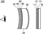
- FIG. 2 conceptually shows another example of the virtual reality display device of the first embodiment.
- Virtual reality display device 102 shown in FIG. It has a substrate 34 , a first optically anisotropic layer 80 , a third optically anisotropic layer 90 , a reflective polarizer 40 and an absorptive linear polarizer 22 .
- the first optically anisotropic layer 80 is a layer made of a negative birefringence resin.
- the third optically anisotropic layer 90 is a ⁇ /4 retardation layer.
- the reflective polarizer 40 is a reflective linear polarizer.
- the antireflection layer 50 is not provided on the surface of the ⁇ /4 retardation layer 11 . However, also in this example, the antireflection layer 50 may be provided on the surface of the ⁇ /4 retardation layer 11 . This also applies to the virtual reality display device 104 shown in FIG. 3, which will be described later.
- the lens substrate 34 is a plate-like member having one convex surface and the other concave surface.
- An anisotropic layer 80, a third optically anisotropic layer 90, a reflective polarizer 40 and an absorptive linear polarizer 22 are laminated, molded into a curved surface, and bonded.
- the lens substrate 34 is made of a material that is transparent to visible light and has a small phase difference, preferably a material that has no phase difference, such as glass or an acrylic plate, similar to the substrate 36 described above. .
- the lens substrate 34 has a convex surface and a concave surface.
- the reflective polarizer 40 and the absorptive linear polarizer 22 are also laminated, shaped into a curved surface, and bonded together. Therefore, the operation of the virtual reality display device 102 shown in FIG. 2 is similar to that of the virtual reality display device 100 shown in FIG.
- the third optically anisotropic layer 90 ( ⁇ /4 retardation layer) is a specific layer in the first embodiment, and the optical laminate is the first optically anisotropic layer. It has an anisotropic layer 80 (a layer made of a negatively birefringent resin) and a third optically anisotropic layer 90 . Further, the half mirror 30, the lens substrate 34, the first optically anisotropic layer 80, the third optically anisotropic layer 90, the reflective polarizer 40, and the absorptive linear polarizer 22 are the same as those of the first embodiment. Construct an optical lens.
- FIG. 3 conceptually shows another example of the virtual reality apparatus of the first embodiment.
- Virtual reality display device 104 shown in FIG. Substrate 34, first optically anisotropic layer 80, reflective polarizer 40A (fourth optically anisotropic layer), third optically anisotropic layer 90 and absorptive linear polarizer 22 .
- the first optically anisotropic layer 80 is a layer made of a negative birefringence resin.
- the third optically anisotropic layer 90 is a ⁇ /4 retardation layer.
- the reflective polarizer 40A is a reflective circular polarizer having a cholesteric liquid crystal layer.
- the lens substrate 34 is the same as the above, and the half mirror 30 is molded into a curved surface on the convex side and bonded, and the concave side is the first optically anisotropic layer 80 and the reflective polarizer.
- the third optically anisotropic layer 90 and the linear absorption polarizer 22 are laminated, shaped into a curved surface, and bonded.
- the reflective polarizer 40A (reflective circular polarizer) and the third optically anisotropic layer 90 ( ⁇ /4 retardation layer) are specific layers in the first embodiment, and the optical laminate is It has a first optically anisotropic layer 80 (negative birefringent resin layer), a reflective polarizer 40A and a third optically anisotropic layer 90 .
- the half mirror 30, the lens substrate 34, the first optically anisotropic layer 80, the reflective polarizer 40A, the third optically anisotropic layer 90, and the absorption linear polarizer 22 are the same as those of the first embodiment. Construct an optical lens.
- the left-handed circularly polarized light converted by the ⁇ /4 retardation layer 11 then enters the half mirror 30 and half of it is transmitted.
- the left-handed circularly polarized light transmitted through the half mirror 30 is transmitted through the lens substrate 34 and the first optically anisotropic layer 80 (negative birefringent resin layer), and is converted into a reflective circular polarizer having a cholesteric liquid crystal layer.
- the reflective polarizer 40A is a reflective circular polarizer that reflects left-handed circularly polarized light and transmits other light. Therefore, left-handed circularly polarized light incident on the reflective polarizer 40A is reflected by the reflective polarizer 40A, passes through the first optically anisotropic layer 80 and the lens substrate 34, and enters the half mirror 30.
- the reflective polarizer 40A is a reflective circular polarizer (cholesteric liquid crystal layer) that reflects left-handed circularly polarized light and transmits other light. Therefore, the right-handed circularly polarized light incident on the reflective polarizer 40A passes through the antireflection layer 40A and enters the third optically anisotropic layer 90.
- FIG. 1 A reflective circular polarizer (cholesteric liquid crystal layer) that reflects left-handed circularly polarized light and transmits other light. Therefore, the right-handed circularly polarized light incident on the reflective polarizer 40A passes through the antireflection layer 40A and enters the third optically anisotropic layer 90.
- the third optically anisotropic layer 90 is a ⁇ /4 retardation layer arranged with the direction of the slow axis aligned so as to convert right-handed circularly polarized light into linearly polarized light in the vertical direction of the paper.
- the absorbing linear polarizer 22 is a linear polarizer arranged with transmission axes aligned so as to transmit linearly polarized light in the vertical direction of the paper surface. Therefore, the right-handed circularly polarized light incident on the third optically anisotropic layer 90 is converted by the third optically anisotropic layer 90 into linearly polarized light in the up-down direction of the plane of the drawing, and then transmitted through the absorbing linear polarizer 22. Then, it is observed by the user of the virtual reality display device 100 as a virtual reality image.
- the absorptive linear polarizer 22 blocks the light that has unnecessarily passed through the reflective polarizer 40A and prevents leakage light (ghost) from being observed by the user of the virtual reality display device 100. be. That is, when the left-handed circularly polarized light first enters the reflective polarizer 40A, some left-handed circularly polarized light is not reflected by the reflective polarizer 40A and is unnecessarily transmitted through the reflective polarizer 40A.
- this left-handed circularly polarized light is converted into linearly polarized light perpendicular to the paper surface by the third optically anisotropic layer 90, which is a ⁇ /4 retardation layer that converts right-handed circularly polarized light into linearly polarized light in the vertical direction of the paper surface. be done. Therefore, this linearly polarized light is absorbed by the absorptive linear polarizer 22, which is a linear polarizer arranged with its transmission axis aligned so that the linearly polarized light in the vertical direction of the paper is transmitted, so that it is used as leakage light. You can prevent people from observing you.
- the first optically anisotropic layer 80 containing a negative birefringent resin and the third optically anisotropic The optical layered body having the optical layer 90 is molded into a curved surface and bonded to the convex surface of the lens substrate 34, which is a convex lens.
- a first optically anisotropic layer 80 containing a negative birefringent resin and a third optically anisotropic layer 90 that is a ⁇ /4 retardation layer. is formed into a curved surface and bonded to the concave surface of the lens substrate 34 .
- the optically anisotropic layer is stretched to develop a retardation in the optically anisotropic layer. Phase difference changes.
- the optical layered body is stretched at a different draw ratio depending on the location, and the amount of retardation, the amount of change, etc., differs depending on the location.
- the optically anisotropic layer is a retardation layer such as a ⁇ /4 retardation layer
- the retardation of the retardation layer may become unintended due to unfavorable development of retardation due to stretching. be. That is, in the virtual reality display device 100 shown in FIG. 1 and the virtual reality display device 102 shown in FIG.
- the retardation of the third optically anisotropic layer 90 may become unintended. If the retardation of the third optically anisotropic layer 90 becomes unintended, the incident left-handed circularly polarized light cannot be converted into proper linearly polarized light, resulting in light including, for example, elliptically polarized light. put away.
- a portion of such light is not reflected by the reflective polarizer 40, which is a reflective linear polarizer, and is transmitted through the reflective polarizer 40 and the absorptive linear polarizer 22, resulting in leakage light (ghost). As a result, it is observed by the user of the virtual reality display device.
- cholesteric liquid crystal layers usually have no retardation.
- the cholesteric liquid crystal layer may exhibit retardation when stretched. That is, in the virtual reality display device 104 shown in FIG. 3, by forming the optical layered body including the reflective polarizer 40A having the cholesteric liquid crystal layer into a curved surface, the reflected circularly polarized light is elliptically polarized or the like. This results in light containing unintended circular polarization. These lights do not properly reciprocate between the reflective polarizer 40 ⁇ /b>A and the half mirror 30 , and part of the light becomes leakage light and is observed by the user of the virtual reality display device 104 .
- the optical laminate of the first embodiment has a first optically anisotropic layer 80 containing a negative birefringence resin.
- a negatively birefringent resin is a resin whose refractive index increases in the direction perpendicular to the stretching direction when stretched.
- the optical laminate of the first embodiment including at least one of the third optically anisotropic layer 90 such as a ⁇ /4 retardation layer and the cholesteric liquid crystal layer is laminated with the lens substrate 34. Therefore, the film is formed into a curved surface and stretched in the bent direction, which changes the phase difference or develops a phase difference that does not exist originally, which causes light leakage.
- the optical layered body of the first embodiment includes a first has an optically anisotropic layer 80 of That is, in the optical layered body of the first embodiment, the first optically anisotropic layer 80 containing a negative birefringent resin is similarly molded into a curved surface together with the ⁇ /4 retardation layer, the cholesteric liquid crystal layer, and the like.
- the refractive index (retardation) of the first optically anisotropic layer 80 ie, the negative birefringent resin
- the change in retardation in the third optically anisotropic layer 90 ( ⁇ /4 retardation layer) caused by stretching is caused by the refractive index in the direction perpendicular to the stretching direction, and by stretching
- the resulting retardation manifestation in the cholesteric liquid crystal layer can be offset. Therefore, according to the optical layered body of the first embodiment, when it is applied to, for example, a pancake lens type virtual reality display device, leakage light can be reduced and a high-quality virtual reality image can be displayed.
- the first optically anisotropic layer, the third optically anisotropic layer, the cholesteric liquid crystal layer (fourth optically anisotropic layer), and the reflective linear polarizer in the optical laminate of the first embodiment are described below. will be described in detail.
- the optical layered body of the first embodiment includes a first optically anisotropic layer containing a negative birefringent resin, and a second layer formed by fixing a uniformly oriented liquid crystalline compound such as a ⁇ /4 retardation layer. 3 optically anisotropic layers, and a specific layer selected from a cholesteric liquid crystal layer (fourth optically anisotropic layer) formed by fixing a helically aligned liquid crystalline compound.
- the optical layered body of the first embodiment may have a second optically anisotropic layer made of a positive birefringent resin.
- the optical laminate of the first embodiment includes the first optically anisotropic layer in addition to the third optically anisotropic layer and the fourth optically anisotropic layer.
- the retardation (refractive index) developed in the first optically anisotropic layer and the change in retardation or development of retardation in the other layers cancel each other out, and the optical laminate as a whole It is possible to suppress the development of the phase difference, the change in the phase difference, and the like.
- the first optically anisotropic layer is made of a negative birefringence resin.
- a negatively birefringent resin is a resin that exhibits negative birefringence when formed into a film. Such resins are also said to have negative intrinsic birefringence.
- the negative birefringence resin is not particularly limited as long as it satisfies the above conditions, but when the film is produced by using the melt extrusion method, it is preferable to use a material with good melt extrusion moldability.
- cyclic olefin-based resins cellulose acylate-based resins, maleimide-based co-resins, polystyrene-based resins, acrylic resins, styrene-based resins such as polystyrenes, polyacrylonitrile-based resins, and polyvinyl acetal-based resins can be used. can be done.
- Cyclic olefin-based resins and cellulose acylate-based resins are positive birefringent resins, that is, when light is incident on a layer formed with molecules uniaxially oriented, the refractive index of the light in the direction of orientation is Excluding resins having a refractive index greater than that of light in the direction perpendicular to the alignment direction.
- the negative birefringent resin used in the first embodiment may contain one resin, or may contain two or more different resins.
- a resin having negative birefringence may be used alone, or two or more may be used in combination when two or more are blended to exhibit negative birefringence. good.
- the negative birefringent resin is a polymer blend consisting of a resin that is solely negative birefringent resin and a resin that is solely positive birefringent resin, the resin that is solely negative birefringent resin.
- the mixing ratio of the resin to the resin which is a positive birefringent resin alone differs depending on the magnitude of the absolute values of the intrinsic birefringence values of both, the birefringence manifestation at the molding temperature, and the like.
- the polymer blend may contain other components in addition to the resin that is a negative birefringent resin alone and the resin that is a positive birefringent resin alone.
- the component is not particularly limited as long as it does not impair the effects of the first embodiment, and can be appropriately selected according to the purpose. Suitable examples include a compatibilizer.
- the compatibilizer can be suitably used when phase separation occurs during blending. It is possible to improve the mixed state with the resin, which is the birefringent resin.
- the negative birefringent resin used in the first embodiment is a polystyrene resin.
- the polystyrene resin refers to resins obtained by polymerizing styrene and styrene derivatives as main components, and copolymer resins of styrene and other resins.
- the polystyrene-based resin that can be used in the first embodiment is not particularly limited as long as it does not impair the effects of the first embodiment, and known polystyrene-based resins and the like can be used.
- copolymer resins of styrene and other resins which can improve birefringence, film strength and heat resistance.
- Copolymer resins include, for example, styrene-acrylonitrile resins, styrene-acrylic resins, styrene-maleic anhydride resins, and multi-component (binary, ternary, etc.) copolymers thereof.
- styrene-acrylonitrile resins styrene-acrylic resins
- styrene-maleic anhydride resins and multi-component (binary, ternary, etc.) copolymers thereof.
- styrene-acrylic resins and styrene-maleic anhydride resins are preferable from the viewpoint of heat resistance and film strength.
- hydrogenation of the styrene-based resin can be preferably used.
- the styrene-maleic anhydride resin include "Daylark D332” manufactured by Nova Chemical Co., Ltd., and the like.
- As the styrene-acrylic resin "Delpet 980N” manufactured by Asahi Kasei Chemical Co., Ltd., which will be described later, can be used.
- the polystyrene-based resin may be an amorphous polystyrene-based resin or a crystalline polystyrene-based resin.
- a crystalline polystyrene-based resin from the viewpoint of mechanical strength, it is preferable to contain a crystalline polystyrene-based resin, while from the viewpoint of facilitating curved surface molding, it is preferable to contain a non-crystalline polystyrene-based resin.
- Crystalline polystyrene resins include polystyrene resins having a syndiotactic structure and polystyrene resins having an isotactic structure. Examples of amorphous polystyrene resins include polystyrene resins having an atactic structure.
- the polystyrene resin may have a syndiotactic structure, an isotactic structure, or an atactic structure, but preferably has a syndiotactic structure.
- a polystyrene-based resin having a syndiotactic structure is particularly excellent in high mechanical strength and low thermal shrinkage.
- the polystyrene resin having a syndiotactic structure used in the first embodiment is a steric resin in which side chains such as phenyl groups and derivatives thereof are alternately positioned in opposite directions with respect to the main chain formed from carbon-carbon bonds.
- the stereoregularity measured by this 13C-NMR method is the abundance ratio of a plurality of consecutive constitutional units, for example, dyads when there are two, triads when there are three, pendad when there are five. can.
- the racemic diad is usually 75 to 100%, preferably 85 to 100%, or the racemic pentahead is 30 to 100%, It preferably has a stereoregularity of 50 to 100%.
- poly(alkylstyrene) includes poly(methylstyrene), poly(ethylstyrene), poly(propylstyrene), poly(butylstyrene), poly(phenylstyrene), poly(vinylnaphthalene), poly(vinylstyrene). ), and poly(acenaphthine).
- Poly(halogenated styrene) includes poly(chlorostyrene), poly(bromostyrene), and poly(fluorostyrene).
- Poly(alkoxystyrene) includes poly(methoxystyrene) and poly(ethoxystyrene). Among these, more preferred are poly(styrene) and poly(methylstyrene), and more preferred is poly(styrene).
- polystyrene resins having a syndiotactic structure may be copolymers other than homopolymers as described above.
- the comonomer component of the copolymer in addition to the monomers constituting the styrene polymer described above, olefin monomers such as ethylene, propylene, butene, hexene and octene, diene monomers such as butadiene and isoprene, and cyclic olefin monomers, Cyclic diene monomers, polar vinyl monomers such as methyl methacrylate, maleic anhydride and acrylonitrile, and the like can be mentioned.
- styrene is the main component, and alkyl styrene, hydrogenated styrene, and halogenated styrene are preferably copolymerized.
- alkyl styrene, hydrogenated styrene, and halogenated styrene are preferably copolymerized.
- p-methylstyrene, m-methylstyrene, p-tert-butylstyrene, p-chlorostyrene, m-chlorostyrene, p-fluorostyrene, or hydrogenated styrene are preferred, and p-methylstyrene is particularly preferred. Styrene.
- the amount of these added is preferably 0 to 30% by mass, more preferably 1 to 20% by mass, and still more preferably 3 to 10% by mass based on the total polymer. Copolymerization of these retards the crystallization rate and suppresses the formation of spherulites. As a result, a polystyrene resin having a syndiotactic structure with high transparency and high folding endurance can be achieved.
- syndiotactic-polystyrene polymer and other polymers may be blended and used.
- preferred polymer blend components are a styrene polymer having a syndiotactic structure and a styrene polymer having an atactic structure as described above.
- polystyrene having a syndiotactic structure is the main component, and p-methylstyrene, m-methylstyrene, p-tert-butylstyrene, p-chlorostyrene, m-chlorostyrene, p-fluoro
- p-methylstyrene, m-methylstyrene, p-tert-butylstyrene, p-chlorostyrene, m-chlorostyrene, p-fluoro A blend of at least one of a homopolymer with a syndiotactic or atactic structure composed of styrene, hydrogenated styrene, etc., and a copolymer with a syndiotactic or atactic structure composed of at least one of these monomers and styrene. preferably.
- Particularly preferred is a blend of p-methylstyrene having a syndiotactic structure and a copolymer of p-methylstyrene having a syndiotactic structure and styrene with polystyrene having a syndiotactic structure.
- the amount of these blended polymers added is preferably 0 to 30% by mass, more preferably 1 to 20% by mass, and still more preferably 3 to 10% by mass of the total amount of the polymers.
- the negative birefringent resin used for the first optically anisotropic layer should have a peak temperature of tan ⁇ (loss tangent (loss factor)) of 170° C. or less from the viewpoint of facilitating molding into a curved shape. is preferred. From the viewpoint of enabling molding at low temperatures, the peak temperature of tan ⁇ is preferably 150° C. or lower, more preferably 130° C. or lower.
- a method for measuring tan ⁇ will be described.
- a dynamic viscoelasticity measuring device (DVA-200, manufactured by IT Keisoku Co., Ltd.)
- a film sample that has been preliminarily conditioned at a temperature of 25 ° C. and a humidity of 60% Rh for 2 hours or more under the following conditions
- Apparatus DVA-200 manufactured by IT Instrument Control Co., Ltd.
- Sample 5 mm, length 50 mm (gap 20 mm) Measurement conditions: Tensile mode Measurement temperature: -150°C to 220°C Temperature rising condition: 5°C/min Frequency: 1Hz Generally, in optical applications, a stretched resin substrate is often used, and the tan ⁇ peak temperature often becomes high due to the stretching treatment.
- a triacetyl cellulose (TAC) substrate for example, TG40 manufactured by Fuji Film Co., Ltd.
- TAC triacetyl cellulose
- Such a first optically anisotropic layer may be used as a support when forming a reflective polarizer, a third optically anisotropic layer, and the like.
- the optical laminate of the first embodiment may have a second optically anisotropic layer.
- the second optically anisotropic layer is made of a positive birefringent resin.
- a positive birefringence resin is a resin that exhibits positive birefringence when formed into a film. Such resins are also said to have positive intrinsic birefringence.
- the second optically anisotropic layer for example, acts as a support when forming the reflective polarizer and the third optically anisotropic layer, etc. After these layers are formed, they are peeled off. good too.
- the positive birefringence resin is not particularly limited, but for example, cellulose acylate, polycarbonate, polysulfone, polyethersulfone, cyclic polyolefin, polyolefin, polyamide, polystyrene, polyester, etc., can be selected from materials having positive birefringence. can be used. Among them, cellulose acylate film, polycarbonate and cyclic polyolefin are preferred.
- the third optically anisotropic layer is a layer in which a uniformly oriented liquid crystalline compound is fixed.
- the third optically anisotropic layer is the specific layer in the first embodiment.
- a layer in which a rod-like liquid crystal compound is uniformly aligned horizontally to the in-plane direction, a layer in which a discotic liquid crystal compound is uniformly aligned perpendicular to the in-plane direction, and the like can be used.
- a retardation layer having reverse dispersion can be produced by uniformly aligning and fixing a rod-shaped liquid crystal compound having reverse dispersion. can.
- the third optically anisotropic layer is exemplified by a ⁇ /4 retardation layer ( ⁇ /4 plate, ⁇ /4 wavelength plate).
- the ⁇ /4 retardation layer used in the first embodiment may be a single-layer type composed of one optically anisotropic layer, or two or more optically anisotropic layers each having a plurality of different slow axes.
- a laminated wave plate configured by laminating layers may also be used.
- Specific examples of the laminated ⁇ / 4 retardation layer include International Publication No. 2013/137464, International Publication No. 2016/158300, Japanese Patent Application Publication No. 2014-209219, Japanese Patent Application Publication No. 2014-209220, International Publication No. Examples include those described in 2014/157079, JP 2019-215416, WO 2016/158300, and WO 2019/160044.
- the fourth optically anisotropic layer is a cholesteric liquid crystal layer formed by fixing a spirally aligned liquid crystalline compound.
- the cholesteric liquid crystal layer is a specific layer in the first embodiment, and is the reflective polarizer 40A (reflective circular polarizer) in the virtual reality display device 104 shown in FIG. 3, as described above.
- a cholesteric liquid crystal layer has a helical structure in which a liquid crystal compound is spirally revolved and stacked.
- As a cycle (helical cycle) a liquid crystal compound that spirals spirally has a structure in which multiple cycles are stacked.
- the cholesteric liquid crystal layer reflects right-handed circularly polarized light or left-handed circularly polarized light in a specific wavelength range and transmits other light, depending on the length of the helical period and the direction of helical rotation (sense) of the liquid crystal compound. do. Therefore, when the virtual reality display device displays a color image, the reflective circular polarizer may include, for example, a cholesteric liquid crystal layer having a central wavelength of selective reflection for red light, a central wavelength for selective reflection of green light, It may have a plurality of cholesteric liquid crystal layers, such as a cholesteric liquid crystal layer having a wavelength and a cholesteric liquid crystal layer having a central wavelength of selective reflection for blue light. In the first embodiment, various known cholesteric liquid crystal layers can be used.
- a reflective linear polarizer may be used instead of the fourth optically anisotropic layer, that is, the cholesteric liquid crystal layer.
- various known reflective linear polarizers can be used.
- the reflective linear polarizer include a film obtained by stretching a layer containing two types of polymers, and a wire grid polarizer, as described in JP-A-2011-053705. From the viewpoint of brightness, a film obtained by stretching a layer containing a polymer is preferable.
- a reflective polarizer (trade name: APF) manufactured by 3M Corporation, a wire grid polarizer (trade name: WGF) manufactured by Asahi Kasei Corporation, and the like can be suitably used.
- a virtual reality display device of the first embodiment includes an image display device that emits at least polarized light, and an optical lens of the first embodiment in which the optical layered body of the first embodiment is bonded to a lens base material.
- the virtual reality display device of the first embodiment may have a ⁇ /4 retardation layer, an absorbing linear polarizer, a half mirror, etc. as described above. It may have additional optical members such as lenses.
- ⁇ /4 retardation layers are available for use in virtual reality display devices.
- the ⁇ /4 retardation layer include a ⁇ /4 retardation layer as a third optically anisotropic layer formed by fixing a uniformly aligned liquid crystal compound, a triacetyl cellulose retardation layer, A polymer carbonate retardation layer, a cycloolefin retardation layer, and the like are exemplified.
- Various types of known linear absorptive polarizers are available, and may be coating polarizers or stretched polarizers. Examples of absorptive linear polarizers include iodine-based polarizers, dye-based polarizers using dichroic dyes, and polyene-based polarizers. Also, an absorbing linear polarizer produced by adsorbing iodine or a dichroic dye to polyvinyl alcohol and stretching the film can be suitably used.
- a known image display device can be used as the image display device.
- display devices such as an organic electroluminescence display device, an LED (Light Emitting Diode) display device, and a micro LED display device, in which self-luminous fine light emitters are arranged on a transparent substrate, are exemplified.
- These self-luminous display devices usually have a (circular) polarizing plate attached to the display surface to prevent reflection on the display surface. Therefore, the emitted light is polarized.
- a liquid crystal display device is exemplified as another image display device. Since the liquid crystal display device also has a polarizing plate on its surface, the emitted light is polarized.
- the image display device is composed of the image display panel 70, the ⁇ /4 retardation layer 13, the absorbing linear polarizer 21 and the ⁇ /4 retardation layer 11. be.
- the image display device may also have an antireflection layer 50, as described above.
- the optically anisotropic film of the second embodiment includes a first optically anisotropic layer having an optic axis, and the first optically anisotropic layer has at least the optic axis orientation continuous in-plane. It has a non-linearly oriented region changing to Moreover, it is preferable that the optically anisotropic film further includes a second optically anisotropic layer that has an optical axis and that the orientation of the optical axis is uniform in the plane.
- a plurality of optically anisotropic layers are generally used in a pancake lens.
- the optically anisotropic film includes both the first optically anisotropic layer and the second optically anisotropic layer and is molded into a three-dimensional shape
- the orientation of the optical axis of the first optically anisotropic layer and the direction of the optical axis of the first optically anisotropic layer It is preferable that the directions of the optical axes of the two optically anisotropic layers change simultaneously.
- the first optically anisotropic layer of the second embodiment has at least the non-linearly oriented region in which the orientation of the optic axis continuously changes within the plane.
- the azimuth of the optical axis changes continuously within the plane means that when short line segments representing the azimuth of the optical axis are drawn at each position within the plane, an envelope connecting these line segments is not a straight line.
- the azimuths of the optical axes are preferably distributed point-symmetrically about at least one point.
- the optical thickness of the first optically anisotropic layer changes continuously in the plane in the non-linearly oriented region.
- the optically anisotropic film is molded into a three-dimensional shape, it is preferable to change the optical thickness in accordance with the different stretch ratios depending on the location so that the optical thickness after molding is uniform in the plane.
- the optical thickness can be changed by adjusting the refractive index, birefringence, optical density, or the like, in addition to adjusting the physical film thickness.
- the optical thickness is the product of the actual film thickness and the birefringence ⁇ n.
- it is obtained by multiplying the actual film thickness by the absorption coefficient.
- the first optically anisotropic layer of the second embodiment may be a retardation layer.
- the retardation layer is preferably a ⁇ /4 plate.
- the 1/4 plate may have a phase difference of approximately 1/4 wavelength in any wavelength in the visible range.
- a retardation plate having a retardation of approximately 138 nm at a wavelength of 550 nm can be preferably used.
- the quarter plate has reverse dispersion with respect to wavelength. .
- having reverse dispersion with respect to wavelength means that the value of the phase difference at the wavelength increases as the wavelength increases.
- the first optically anisotropic layer When the first optically anisotropic layer is a retardation layer, its slow axis is the optical axis in the second embodiment. That is, when the first optically anisotropic layer is a retardation layer, the first optically anisotropic layer has at least a non-linear orientation in which the orientation of the slow axis changes continuously within the plane. have an area.
- the "non-linearly oriented region in which the orientation of the optic axis (slow axis) changes continuously within the plane” The operation of measuring the thickness measurement range and finding the direction of the slow axis in that range is performed multiple times along one direction in the plane, and the direction of the slow axis observed in each measurement range is continuous.
- a region in which the direction of the optical axis (slow axis) changes continuously is referred to as a “non-linearly oriented region in which the orientation of the optic axis (slow axis) changes continuously within the plane”. That is, when the direction of the slow axis of two continuous measurement ranges along one in-plane direction is different, the area including these two measurement ranges is the "non-linearly oriented area”.
- the continuous measurement ranges are not limited to being in contact with each other, they may be spaced apart, and may overlap if the ranges are deviated.
- the size of one measurement range is preferably ⁇ 0.1 to 2 mm, more preferably ⁇ 0.1 to 1 mm.
- interval between continuous measurement ranges is preferably 1 to 10 mm, more preferably 1 to 2 mm.
- the direction of the optical axis changes continuously within the plane
- the direction of the optical axis in each measurement range rotates clockwise or counterclockwise along one direction within the plane. It means that the direction of rotation is changing in either direction.
- the optical axis rotates in one in-plane direction such that the angle formed by the optical axes in continuous measurement ranges becomes smaller.
- the "non-linearly oriented region" will be further described with reference to the diagram of the first optically anisotropic layer 210a shown in FIG. 4, which will be described later.
- the orientation of the optical axis of the first optically anisotropic layer 210a shown in FIG. corresponding to the in-plane position of the measurement range.
- the first optically anisotropic layer 210a shown in FIG. 4 is, for example, laminated along the curved surface of a rotationally symmetrical convex lens or concave lens. Therefore, as will be described later, the first optically anisotropic layer 210a shown in FIG. 4 is formed in a substantially spherical crown shape. Therefore, the region where the first optically anisotropic layer 210a is formed has a substantially circular shape.
- the slow axes of the three measurement ranges on the upper side of the figure rotate clockwise (rightward) from top to bottom. It can be said that the Also, the slow axis in the third measurement range from the top to the slow axis in the sixth measurement range are parallel and not rotated. Furthermore, it can be said that the slow axis of the sixth measurement range from the top to the slow axis of the ninth measurement range rotate counterclockwise (counterclockwise) from top to bottom. .
- the region connecting the first measurement range to the third measurement range from the top in the vertical direction passing through the center is the second measurement range. It corresponds to the "non-linearly oriented area" in the form, and the area connecting the sixth to ninth measuring range from the top corresponds to the "non-linearly oriented area" in the second embodiment.
- Each of the upper non-linearly oriented region and the lower non-linearly oriented region changes along one direction in one direction of rotation.
- the first optically anisotropic layer has such "non-linearly oriented regions".
- the azimuths of the optical axis (slow axis) in each measurement range are distributed point-symmetrically with respect to the center.
- the first optically anisotropic layer changes the orientation (angle) of the optic axis in each measurement range along one in-plane direction, that is, the optic axes of continuous measurement ranges
- the total value of the changed angles is preferably 0 to 10°, more preferably 0 to 5°, and even more preferably 0 to 3°.
- the change in the angle of the optical axis in the continuous measurement range is integrated with the clockwise rotation being positive and the counterclockwise rotation being negative.
- the distribution of the orientation of the optic axis in the first optically anisotropic layer depends on the shape of the first optically anisotropic layer (the radius of curvature of the curved surface, etc.), the shape of other layers to be laminated ( For example, it may be appropriately set according to the second optically anisotropic layer described later) and the like.
- the shape of the molding region in the first optically anisotropic layer may also be appropriately set to a circular shape, an elliptical shape, an irregular shape, or the like according to the shape in which the first optically anisotropic layer is to be molded.
- the first optically anisotropic layer 210a when the first optically anisotropic layer 210a is formed in a substantially spherical crown shape, the closer the region is to the edge, the greater the stretch ratio in the diametrical direction and the circumferential direction. , the stretching rate in the vertical direction and the horizontal direction in the figure differ depending on the position. Therefore, the closer the region is to the peripheral portion, the greater the change in the direction of the optical axis upon molding. Therefore, when the first optically anisotropic layer 210a is formed in a substantially spherical crown shape, the first optically anisotropic layer 210a has a marginal portion to compensate for this change in the direction of the optical axis. It is sufficient to have a non-linearly oriented region in a region close to .
- the first optically anisotropic layer of the second embodiment may be a polarizer layer.
- the polarizer layer preferably contains at least a matrix compound and a dichroic substance, and the degree of orientation of the dichroic substance is 0.95 or more.
- the degree of orientation of the dichroic substance is more preferably 0.97 or more, and the higher the degree of orientation, the more effectively stray light, ghosts, etc. can be suppressed.
- the first optically anisotropic layer When the first optically anisotropic layer is a polarizer layer, its absorption axis is the optical axis in the second embodiment. That is, when the first optically anisotropic layer is a polarizer layer, the first optically anisotropic layer has at least a non-linearly oriented region in which the orientation of the absorption axis changes continuously within the plane.
- the first optically anisotropic layer is a polarizer layer, it has the same configuration as the retardation layer described above, except that the slow axis is read as the absorption axis.
- the orientation of the absorption axis in each measurement range can be obtained with AxoScan.
- the first optically anisotropic layer of the second embodiment is a layer formed by fixing a liquid crystalline compound. Since liquid crystalline compounds can be easily oriented in any direction by photo-alignment or the like, it is also easy to continuously change the orientation of the optic axis within the plane, making it suitable for producing non-linearly oriented regions. ing. Further, after the liquid crystalline compound is oriented, the alignment direction of the liquid crystalline compound can be fixed by fixing by photopolymerization or the like.
- the first optically anisotropic layer is a retardation layer, for example, referring to JP-A-2020-084070, a rod-shaped liquid crystal compound having reverse dispersion is uniformly oriented and fixed.
- the polarizer layer can be produced by orienting and fixing a mixture containing a liquid crystalline compound and a dichroic substance. . That is, the liquid crystalline compound corresponds to the matrix compound described above.
- the second optically anisotropic layer is characterized by uniformly oriented optical axes.
- the second optically anisotropic layer is not particularly limited. It may be a layer produced by stretching. Alternatively, it may be a layer in which a uniformly oriented liquid crystalline compound is fixed.
- the second optically anisotropic layer may be a retardation layer or a polarizer layer, and can be appropriately selected depending on the required function, purpose of use, and the like.
- the optically anisotropic film of the second embodiment is a laminate prepared by directly coating one of the first optically anisotropic layer and the second optically anisotropic layer on the other.
- it may be a laminate produced by separately producing the first optically anisotropic layer and the second optically anisotropic layer and then laminating them together.
- the optically anisotropic film of the second embodiment may additionally contain a substrate and the like.
- the base material is not particularly limited, it is preferable that the peak temperature of tan ⁇ (loss tangent (loss factor)) is 170° C. or less from the viewpoint of facilitating molding into a three-dimensional shape. From the viewpoint of enabling molding at low temperatures, the peak temperature of tan ⁇ is preferably 150° C. or lower, more preferably 130° C. or lower.
- Base materials having a tan ⁇ peak temperature of 170° C. or less include, for example, polyacrylates, polymethacrylates, cyclic polyolefins, and polyolefins.
- a method for measuring tan ⁇ will be described.
- a dynamic viscoelasticity measuring device (DVA-200, manufactured by IT Keisoku Co., Ltd.)
- a film sample that has been preliminarily conditioned at a temperature of 25 ° C. and a humidity of 60% Rh for 2 hours or more under the following conditions
- Apparatus DVA-200 manufactured by IT Instrument Control Co., Ltd.
- Sample 5 mm, length 50 mm (gap 20 mm) Measurement conditions: Tensile mode Measurement temperature: -150°C to 220°C Temperature rising condition: 5°C/min Frequency: 1Hz Generally, in optical applications, a stretched resin substrate is often used, and the tan ⁇ peak temperature often becomes high due to the stretching treatment.
- a triacetyl cellulose (TAC) substrate for example, TG40 manufactured by Fuji Film Co., Ltd.
- TAC triacetyl cellulose
- the molded article of the second embodiment is an optically anisotropic film including a first optically anisotropic layer and a second optically anisotropic layer molded into a three-dimensional shape including a curved surface,
- the optic axis of the first optically anisotropic layer and the optic axis of the second optically anisotropic layer form an angle of 45° in the non-linearly oriented regions of the first optically anisotropic layer.
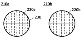
- FIG. 4 shows an example of a change in distribution of optic axis orientations in the non-linearly oriented regions of the first optically anisotropic layer.
- Reference numeral 210a is the first optically anisotropic layer before the optically anisotropic film is formed into a three-dimensional shape.
- the azimuths 220a of the optical axes are distributed point-symmetrically with the center of the non-linearly oriented region 230 as the center.
- the first optically anisotropic layer 210b is partially stretched at different stretch ratios, thereby changing the orientation of the optical axis, as indicated by reference numeral 220b. distribution.
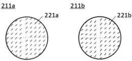
- FIG. 5 shows changes in the distribution of the orientations of the optical axes of the second optically anisotropic layer.
- Reference numeral 211a denotes a second optically anisotropic layer before the optically anisotropic film is formed into a three-dimensional shape.
- the azimuth 221a of the optical axis is uniformly oriented.
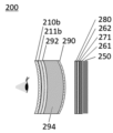
- the second optically anisotropic layer 211b after the optically anisotropic film has been formed into a three-dimensional shape is partially stretched at different stretch ratios, thereby changing the orientation of the optical axis, and the reference numeral 221b It becomes a non-uniform distribution like FIG. 6 shows changes in the distribution of the optical axes in the optically anisotropic film containing the first optically anisotropic layer and the second optically anisotropic layer.
- Reference numeral 240a denotes an optically anisotropic film before the optically anisotropic film is formed into a three-dimensional shape.
- the angles between the optical axes of the respective optically anisotropic layers differ depending on the location.
- the orientation of each optic axis has changed due to molding, and as a result, the angle between each optic axis in the non-linearly oriented region 230 is It is 45° regardless of location.
- thermoforming or vacuum forming can be used as a method for forming the optically anisotropic film into a three-dimensional shape. Specifically, insert molding as described in JP-A-2004-322501, WO2010/1867, and vacuum molding and injection molding as described in JP-A-2012-116094. , air pressure molding, vacuum coating molding, in-mold transfer, mold press, and the like. It is also preferable to heat during molding, preferably from 80°C to 170°C, more preferably from 100°C to 150°C, and even more preferably from 110°C to 140°C.
- the optically anisotropic film of the second embodiment molded into a three-dimensional shape can be suitably used as part of a so-called pancake lens in a virtual reality display device.
- FIG. 7 is a diagram conceptually showing an example of a virtual reality display device having the optically anisotropic film of the second embodiment molded into a three-dimensional shape.
- a virtual reality display device 200 shown in FIG. It has a mirror 290, a lens substrate 294, a reflective circular polarizer 292, a second optically anisotropic layer 211b, and a first optically anisotropic layer 210b.
- the ⁇ /4 retardation layer 261, the absorbing linear polarizer 271, the ⁇ /4 retardation layer 262, and the antireflection layer 280 are arranged in this order on the display surface side of the image display panel 250. Laminated.
- the lens base material 294 is arranged at a predetermined distance from the image display panel 250 (antireflection layer 280), and has a convex surface on the image display panel 250 side and a concave surface on the opposite side.
- the half mirror 290 is laminated on the convex surface side of the lens substrate 294 and curved along the curved shape of the convex surface of the lens substrate 294 .
- a reflective circular polarizer 292, a second optically anisotropic layer 211b, and a first optically anisotropic layer 210b are laminated in this order on the concave surface side of the lens substrate 294. They are curved along the curved shape of the concave surface.
- the first optically anisotropic layer 210b is a polarizer layer
- the second optically anisotropic layer 211b is a retardation layer ( ⁇ /4 retardation layer).
- the reflective circular polarizer 292 is a circular polarizer that reflects left-handed circularly polarized light and transmits right-handed circularly polarized light. reflected.
- the right-handed circularly polarized light reflected by the half mirror 290 passes through the lens base material 294 and enters the reflective circular polarizer 292. Since the reflective circular polarizer 292 is a circular polarizing plate that transmits right-handed circularly polarized light, The incident right-handed circularly polarized light passes through the reflective circular polarizer 292 and enters the second optically anisotropic layer 211b. Right-handed circularly polarized light incident on the second optically anisotropic layer 211b, which is a retardation layer, is converted into linearly polarized light and is incident on the first optically anisotropic layer 210b.
- the first optically anisotropic layer 210b which is a polarizer layer, is arranged so as to transmit this linearly polarized light
- this linearly polarized light is transmitted through the first optically anisotropic layer 210b and reaches the user U emitted toward
- the half mirror 290 is formed in a concave shape. It is illuminated and emitted to the viewing side. Thereby, the light appears to be emitted from a position farther than the image display panel 250 . Therefore, to the user U who sees this light, the image display panel 250 looks as if the light is being emitted from the back side (the side opposite to the user U side). As a result, the video (image) displayed by the image display panel 250 is viewed by the user U as a virtual image behind the image display panel 250 .
- the transmitted left-handed circularly polarized light passes through the antireflection layer 280, enters the ⁇ /4 retardation layer 262, and is converted into linearly polarized light.
- This linearly polarized light is transmitted through the absorbing linear polarizer 271, enters the ⁇ /4 retardation layer 261, and is converted into circularly polarized light.
- This circularly polarized light is reflected by the surface of the image display panel 250 or the like, and enters the ⁇ /4 retardation layer 261 again.
- part of the light beam emitted from the image display panel does not reciprocate between the reflective polarizer and the half mirror due to polarization disturbance, undesirable reflection, etc., and leakage light This may lead to the occurrence of double images, a decrease in contrast, and the like.
- the optically anisotropic film obtained by laminating the can be set to an appropriate angle (45°). Therefore, leaked light can be sufficiently shielded, and the occurrence of double images and deterioration of contrast can be prevented.
- a reflective circular polarizer according to the third embodiment is a reflective circular polarizer having a light reflecting layer formed by fixing a cholesteric liquid crystal phase, wherein the helical pitch of the cholesteric liquid crystal phase has an in-plane distribution. do.
- a conventional reflective circular polarizer with a light reflecting layer made of a fixed cholesteric liquid crystal phase is molded into a non-planar shape and applied to a virtual reality display device, it is speculated that the color of the main image will change due to the following mechanism. be done.
- the reflective circular polarizer is molded in a non-planar shape, the stretch ratio of the layer in which the cholesteric liquid crystal phase is fixed is not uniform in the plane.
- the helical pitch of the cholesteric liquid crystal phase in the light reflecting layer has an in-plane distribution. Even if there is a wavelength shift due to the difference in , the change in the in-plane reflection wavelength range is made more uniform in the reflective circular polarizer after molding, and the main image of the main image depending on the position in the field of view when applied to a virtual reality display device. Color change can be suppressed.
- a layer in which a cholesteric liquid crystal phase is fixed or "a light reflecting layer in which a cholesteric liquid crystal phase is fixed” is also referred to as a “cholesteric liquid crystal layer” for convenience.
- the reflective circular polarizer according to the third embodiment is an optical member that separates incident light into right-handed circularly polarized light and left-handed circularly polarized light, specularly reflects one circularly polarized light, and transmits the other circularly polarized light.
- a reflective circular polarizer according to the third embodiment has a light reflecting layer having a cholesteric liquid crystal layer.
- a light reflecting layer having a cholesteric liquid crystal layer functions alone as a reflective circular polarizer, and the film has no reflection axis and transmission axis.
- the reflective circular polarizer when stretched or molded into a three-dimensional shape, etc., there is little concern that the polarization axis will be distorted, and the degree of polarization will not easily decrease due to the polarization axis distortion. However, it is preferable because the transmitted light has a high degree of polarization.
- a reflective circular polarizer having a light reflecting layer formed by fixing a cholesteric liquid crystal phase for example, an optical film described in JP-A-2020-060627 can be used.
- FIG. 11 conceptually shows an example of a reflective circular polarizer according to the third embodiment.
- a first light reflecting layer 331, a second light reflecting layer 332, a third light reflecting layer 333, and a fourth light reflecting layer 334 are arranged in this order.
- Each light reflecting layer is a layer formed by fixing a cholesteric liquid crystal phase having an in-plane distribution of helical pitches.
- the reflective circular polarizer according to the third embodiment is not limited to the mode shown in FIG.
- the reflective circular polarizer according to the third embodiment may have at least one light reflecting layer formed by fixing a cholesteric liquid crystal phase having an in-plane distribution of helical pitches. That is, the number of cholesteric liquid crystal layers having an in-plane distribution of helical pitch may be one or plural.
- the reflective circular polarizer according to the third embodiment it is assumed in advance that it is formed in a non-planar shape and stretched at a non-uniform stretch ratio in the plane, and the reflection wavelength range is shifted.
- In-plane distribution of helical pitch is set. That is, the size of the helical pitch of the cholesteric liquid crystal phase is selected so that the reflection wavelength range is in an appropriate range according to the wavelength shift due to stretching at each place in the plane, and the reflection is performed according to the position in the plane. Regions with different wavelength ranges are provided.
- the in-plane distribution is set so that the helical pitch of the cholesteric liquid crystal phase increases toward the center.
- the in-plane distribution of the helical pitch of the cholesteric liquid crystal phase in the light-reflecting layer can be determined based on well-known techniques based on the composition of the light-reflecting layer (the type and content of the liquid crystal compound and the chiral agent described later), the layer structure of the reflective circular polarizer, and the , the size and shape after molding, the target reflection wavelength range, etc., and can be appropriately selected and set.
- the reflective circular polarizer according to the third embodiment includes a light reflecting layer (hereinafter also referred to as “light reflecting layer R”) obtained by fixing a cholesteric liquid crystal phase containing a rod-shaped liquid crystal compound, and a cholesteric liquid crystal containing a discotic liquid crystal compound. It is preferable to have a light reflecting layer (hereinafter also referred to as "light reflecting layer D") formed by fixing a liquid crystal phase.
- the cholesteric liquid crystal phase containing the rod-like liquid crystal compound has a positive Rth
- the cholesteric liquid crystal phase containing the discotic liquid crystal compound has a negative Rth. This is because it is possible to suppress the generation of ghosts even for incident light from an oblique direction.
- the light reflecting layer R and the light reflecting layer D may have one or more layers, or two or more layers.
- the reflective circular polarizer may have another layer other than the light reflecting layer R such as a light reflecting layer D between the two or more light reflecting layers R. , does not have to be.
- another layer other than the light reflecting layer D such as a light reflecting layer R is provided between the two or more light reflecting layers D. may or may not have.
- a light reflecting layer R formed by fixing a cholesteric liquid crystal phase containing a rod-like liquid crystal compound and a light reflecting layer D formed by fixing a cholesteric liquid crystal phase containing a discotic liquid crystal compound are alternately arranged. It is preferable to have a laminated structure of
- the state of canceling Rth can be represented by a formula as follows.
- SRth i be the sum of Rth of each layer up to layer L i . Specifically, the following formula is obtained.
- the absolute values of all SRth i are preferably 0.3 ⁇ m or less, more preferably 0.2 ⁇ m or less, and even more preferably 0.1 ⁇ m or less.
- Rth i of each layer in the above formula is determined by the formula for calculating Rth described above.
- the reflective circular polarizer according to the third embodiment preferably has a blue light reflecting layer, a green light reflecting layer, a yellow light reflecting layer, and a red light reflecting layer in this order.
- the center wavelength of reflected light from the blue light reflecting layer is preferably within the range of 430 to 480 nm.
- the central wavelength of reflected light from the green light reflecting layer is preferably within the range of 520-570 nm.
- the center wavelength of the light reflected by the yellow light reflecting layer is preferably within the range of 570 to 620 nm.
- the center wavelength of the reflected light of the red light reflecting layer is preferably in the range of 620-670 nm.
- the reflective circular polarizer according to the third embodiment includes at least a blue light reflecting layer having a reflectance of 40% or more at a wavelength of 460 nm, a green light reflecting layer having a reflectance of 40% or more at a wavelength of 550 nm, and a light having a wavelength of 600 nm. It is preferable to have a yellow light reflecting layer having a reflectance of 40% or more and a red light reflecting layer having a reflectance of 40% or more at a wavelength of 650 nm in this order. With such a configuration, high reflection characteristics can be exhibited over a wide wavelength range in the visible region.
- the above reflectance is the reflectance when unpolarized light is incident on the reflective circular polarizer at each wavelength.
- the blue light reflective layer, green light reflective layer, yellow light reflective layer, and red light reflective layer formed by fixing the cholesteric liquid crystal phase have a pitch gradient in which the helical pitch of the cholesteric liquid crystal phase is continuously changed in the thickness direction. It may have layers. For example, referring to Japanese Unexamined Patent Application Publication No. 2020-060627, etc., a green light reflecting layer and a yellow light reflecting layer can be produced continuously.
- the blue light reflective layer is circularly polarized is preferably placed on the side opposite to the retardation layer that converts the light into linearly polarized light.
- the blue light reflecting layer passes through the blue light reflecting layer, the green light reflecting layer, the yellow light reflecting layer and the red light reflecting layer in this order.
- the present inventors believe that the reason why ghost generation can be suppressed by arranging the blue light reflecting layer on the light source side is that the influence of Rth can be suppressed. The presumed mechanism is described below.
- the film thickness required to obtain a sufficient reflectance increases toward the longer wavelength side. Therefore, if there is a light reflecting layer that reflects long-wavelength light on the light source side, the film thickness of the layer increases, and as a result, Rth received by the light passing through the layer increases. For this reason, it is considered that the reflection band of the light reflecting layer disposed on the light source side is preferably on the short wavelength side.
- the blue light reflecting layer, the green light reflecting layer, the yellow light reflecting layer, and the red light reflecting layer of the reflective circular polarizer are each a light reflecting layer R formed by fixing a cholesteric liquid crystal phase containing a rod-like liquid crystal compound, and a light reflecting layer D formed by fixing a cholesteric liquid crystal phase containing a discotic liquid crystal compound.
- the reflective circular polarizer includes a blue light reflecting layer composed of a cholesteric liquid crystal phase containing a discotic liquid crystal compound, a green light reflecting layer composed of a cholesteric liquid crystal phase containing a rodlike liquid crystal compound, and a discotic liquid crystal. It is preferable to have a yellow light reflecting layer composed of a cholesteric liquid crystal phase containing a compound and a red light reflecting layer composed of a cholesteric liquid crystal phase containing a rod-like liquid crystal compound in this order.
- the reflective circular polarizer when it includes a blue light reflecting layer, a green light reflecting layer, a yellow light reflecting layer and a red light reflecting layer, it may have two or more blue light reflecting layers. green light reflecting layer, two or more yellow light reflecting layers, and two or more red light reflecting layers.
- the number of layers of the blue light reflecting layer, the green light reflecting layer, the yellow light reflecting layer, or the red light reflecting layer included in the reflective circular polarizer is two or more, each color has at least one light reflecting layer R and at least It is preferable to have the light reflection layer D of one layer.
- the reflective circular polarizer preferably has an infrared light reflective layer having a reflectance of 40% or more at a wavelength of 800 nm, assuming that the reflective wavelength region is shifted to a shorter wavelength due to stretching or molding. Moreover, it is also preferable to preliminarily set a reflection wavelength region wider than the required wavelength region, assuming that the stretch ratio is different at each place in the plane.
- the thickness of the reflective circular polarizer is not particularly limited, it is preferably 30 ⁇ m or less, more preferably 15 ⁇ m or less, from the viewpoint of thinning.
- the lower limit is not particularly limited, it is preferably 1 ⁇ m or more, for example.
- a cholesteric liquid crystal phase is formed by dissolving a liquid crystal compound, a chiral agent, a polymerization initiator, and optionally a surfactant in a solvent, on a support, or by forming a liquid crystal composition on the support. It is formed by applying and drying to obtain a coating film, aligning the liquid crystal compound in the coating film, and irradiating the coating film with actinic rays to cure the liquid crystal composition. can. Thereby, a cholesteric liquid crystal phase having a cholesteric liquid crystal structure in which cholesteric regularity is fixed can be formed.
- Method for producing reflective circular polarizer (Formation of cholesteric liquid crystal phase having in-plane distribution of helical pitch)
- a method of imparting an in-plane distribution to the helical pitch of the cholesteric liquid crystal phase for example, there is a method of using a chiral agent whose HTP is changed by photoisomerization.
- a cholesteric liquid crystal phase formed by applying (in some cases, heat-treating) a liquid crystal composition containing a chiral agent whose HTP is changed by photoisomerization and orienting it light corresponding to photoisomerization is applied.
- irradiating it is possible to change the HTP of the chiral agent, thereby changing the helical pitch of the cholesteric liquid crystal phase and changing the reflection wavelength.
- patterned light irradiation is performed using an exposure mask or the like on the oriented cholesteric liquid crystal phase, and photoisomerization is performed, resulting in a pattern in which the reflection wavelength is changed only in the light-irradiated region. is obtained.
- the entire coating film is exposed to light for curing the liquid crystal composition, and the liquid crystal composition is polymerized to finally obtain a cholesteric liquid crystal layer (pattern) having an in-plane distribution of the helical pitch.
- cholesteric liquid crystal layer can be obtained.
- the patterned cholesteric liquid crystal layer no longer undergoes photoisomerization and has stable properties.
- the Measures for separating the two and performing light irradiation for each include, for example, distinction based on oxygen concentration, distinction based on exposure wavelength, and the like.
- photoisomerization is less affected by the oxygen concentration, but curing (depending on the initiator used) is less likely to occur as the oxygen concentration increases. Therefore, photoisomerization is performed under high oxygen concentration conditions, for example, in the air, and curing is performed under low oxygen concentration conditions, for example, in a nitrogen atmosphere at an oxygen concentration of 300 ppm by volume or less, thereby separating photoisomerization and curing. easier to implement.
- photoisomerization by the chiral agent tends to proceed at the absorption wavelength of the chiral agent, and curing tends to proceed at the absorption wavelength of the photopolymerization initiator. Therefore, if the chiral agent and the photopolymerization initiator are selected so that the chiral agent and the photopolymerization initiator have different absorption wavelengths, it becomes possible to separate photoisomerization and curing depending on the exposure wavelength.
- photoisomerization and curing may be performed under heating conditions as necessary.
- the temperature for heating is preferably 25 to 140°C, more preferably 30 to 100°C.
- the aligned cholesteric liquid crystal phase is first irradiated with light for curing in a pattern using an exposure mask or the like. After that, by irradiating the entire surface with light for photoisomerization, since the pitch change due to photoisomerization can no longer occur in the previously cured region, photoisomerization can occur only in the region that has not been previously cured. A pitch change occurs, causing a change in the reflected wavelength. In this case also, after obtaining the pattern, the entire cholesteric liquid crystal layer is exposed to light for curing the liquid crystal composition, and the liquid crystal composition is polymerized to obtain the final patterned cholesteric liquid crystal layer.
- the reflective circular polarizer according to the third embodiment has a plurality of light reflecting layers
- the plurality of light reflecting layers are in direct contact with each other without an adhesive layer interposed therebetween.
- a coating liquid containing a liquid crystal compound is directly applied onto the already-formed light-reflecting layer (adjacent layer) to form the light-reflecting layer without an adhesive layer. can.
- the alignment direction (slow axis direction) of the liquid crystal compound so as to change continuously at the interface.
- a coating liquid containing the rod-shaped liquid crystal compound is directly applied, and a light beam containing the discotic liquid-crystal compound is applied. It is also possible to align so that the slow axis direction changes continuously at the interface by the alignment control force of the discotic liquid crystal compound of the reflective layer.
- each light-reflecting layer can be adhered by any adhesion method, for example, by using an adhesive or an adhesive. can. Any commercially available adhesive can be used as the adhesive. From the viewpoint of thinning and the viewpoint of reducing the surface roughness Ra of the laminated optical body, the thickness of the pressure-sensitive adhesive layer is preferably 25 ⁇ m or less, more preferably 15 ⁇ m or less, and 6 ⁇ m or less. More preferred. In addition, it is preferable that the adhesive is less likely to outgas.
- the adhesive when drawing or molding is performed, a vacuum process or a heating process may be performed, and it is preferable that outgassing does not occur even under these conditions.
- a commercially available adhesive or the like can be arbitrarily used, and for example, an epoxy resin-based adhesive or an acrylic resin-based adhesive can be used.
- the thickness of the adhesive layer is preferably 25 ⁇ m or less, more preferably 5 ⁇ m or less, and 1 ⁇ m or less from the viewpoint of thinning and reducing the surface roughness Ra of the reflective circular polarizer. is more preferred.
- the adhesive preferably has a viscosity of 300 cP or less, more preferably 100 cP or less, from the viewpoints of thinning the adhesive layer and coating the adherend with a uniform thickness.
- the pressure-sensitive adhesive or the adhesive is used so that the surface irregularities of the layer to be adhered can be embedded from the viewpoint of reducing the surface roughness Ra of the reflective circular polarizer.
- the appropriate viscoelasticity or thickness can also be selected. From the viewpoint of embedding surface irregularities, it is preferable that the pressure-sensitive adhesive or adhesive have a viscosity of 50 cP or more.
- the thickness is preferably greater than the height of the surface unevenness.
- Methods for adjusting the viscosity of the adhesive include, for example, a method using an adhesive containing a solvent.
- the viscosity of the adhesive can be adjusted by adjusting the solvent ratio. Further, by drying the solvent after applying the adhesive to the adherend, the thickness of the adhesive can be further reduced.
- the pressure-sensitive adhesive or adhesive used to bond each layer should have a small difference in refractive index between adjacent layers. is preferred. Since the liquid crystal layer has birefringence, the refractive indices in the fast axis direction and the slow axis direction are different. When the average refractive index is n ave , the absolute value of the difference between the n ave and the refractive index of the adjacent adhesive layer or adhesive layer is preferably 0.075 or less, more preferably 0.05 or less, and 0.025 or less. is more preferred.
- the refractive index of the pressure-sensitive adhesive or adhesive can be adjusted by, for example, mixing fine particles of titanium oxide, fine particles of zirconia, or the like.
- the reflective circular polarizer, the retardation layer, and the linear polarizer have in-plane refractive index anisotropy, but the refractive index difference between adjacent layers is 0.10 in all in-plane directions. The following are preferable. Therefore, the pressure-sensitive adhesive or adhesive may have in-plane refractive index anisotropy.
- the refractive index adjusting layer is preferably a cholesteric liquid crystal layer.
- the average refractive index of the refractive index adjusting layer is smaller than the average refractive index of the reflective circular polarizer.
- the center wavelength of the reflected light from the refractive index adjustment layer may be smaller than 430 nm or larger than 670 nm, and is more preferably smaller than 430 nm.
- the adhesive layer between each layer has a thickness of 100 nm or less.
- the thickness of the adhesive layer is 100 nm or less, light in the visible range is less sensitive to difference in refractive index, and unnecessary reflection can be suppressed.
- the thickness of the adhesive layer is more preferably 50 nm or less, still more preferably 30 nm or less.
- a method for forming an adhesive layer having a thickness of 100 nm or less for example, there is a method of vapor-depositing a ceramic adhesive such as silicon oxide (SiOx layer) on the bonding surface.
- the bonding surface of the bonding member can be subjected to surface modification treatment such as plasma treatment, corona treatment, saponification treatment, etc., or can be provided with a primer layer before bonding.
- the type and thickness of the adhesive layer can be adjusted for each bonding surface.
- an adhesive layer having a thickness of 100 nm or less can be provided by the procedures shown in (1) to (3) below.
- (1) A layer to be laminated is attached to a temporary support made of a glass substrate.
- a SiOx layer having a thickness of 100 nm or less is formed by vapor deposition or the like on both the surface of the layer to be laminated and the surface of the layer to be laminated.
- Vapor deposition can be performed using SiOx powder as a vapor deposition source, for example, using a vapor deposition apparatus (model ULEYES) manufactured by ULVAC, Inc., or the like. Moreover, it is preferable to subject the surface of the formed SiOx layer to a plasma treatment. (3) After bonding the formed SiOx layers together, the temporary support is peeled off. It is preferable to perform lamination at a temperature of 120° C., for example.
- Each layer may be applied, adhered, or laminated by a roll-to-roll method or a sheet-by-sheet method.
- the roll-to-roll method is preferable from the viewpoint of improving productivity and reducing misalignment of each layer.
- the single-wafer method is preferable because it is suitable for small-lot production of a wide variety of products, and because it allows selection of a special bonding method such that the thickness of the bonding layer is 100 nm or less.
- methods for applying an adhesive to an adherend include roll coating, gravure printing, spin coating, wire bar coating, extrusion coating, direct gravure coating, reverse gravure coating, and die coating. well-known methods such as a method, a spray method, and an inkjet method.
- the reflective circular polarizer according to the third embodiment may have a layer other than the cholesteric liquid crystal layer in which the helical pitch has an in-plane distribution.
- Layers other than the cholesteric liquid crystal layer having an in-plane distribution of helical pitch include, for example, a support, an alignment layer, and a light reflecting layer other than a layer composed of a cholesteric liquid crystal phase having an in-plane distribution of helical pitch.
- the support and alignment layers may be temporary supports that are peeled off and removed when making the laminated optical body. When a temporary support is used, it is preferable to remove the temporary support by peeling after transferring the reflective circular polarizer to another laminate.
- the type of support is not particularly limited, but is preferably transparent.
- examples include cellulose acylate, polycarbonate, polysulfone, polyethersulfone, polyacrylate and polymethacrylate, cyclic polyolefin, polyolefin, polyamide, polystyrene, and polyester. can be used. Among them, a cellulose acylate film, a cyclic polyolefin film, a polyacrylate film or a polymethacrylate film is preferable.
- the support is a temporary support
- a support with high tear strength is preferable from the viewpoint of preventing breakage during peeling.
- polycarbonate and polyester films are preferred.
- the support preferably has a small retardation from the viewpoint of suppressing adverse effects on the degree of polarization of transmitted light.
- the magnitude of Re is preferably 10 nm or less
- the absolute value of the magnitude of Rth is preferably 50 nm or less.
- the position of the temporary support is important for quality inspection of the reflective circular polarizer and other laminates in the manufacturing process of the laminated optical body. A small phase difference is preferred.
- the reflective circular polarizer according to the third embodiment is preferably transparent to near-infrared light.
- a non-planar reflective circular polarizer according to the third embodiment is a non-planar reflective circular polarizer formed by molding a reflective circular polarizer having a light reflecting layer formed by fixing a cholesteric liquid crystal phase, wherein the cholesteric liquid crystal phase
- the in-plane distribution of the helical pitch of is 1% or less.
- a non-planar reflective circular polarizer for example, a non-planar reflective circular polarizer formed by molding a reflective circular polarizer having a light reflecting layer having an in-plane distribution of the helical pitch of the cholesteric liquid crystal phase is formed into a non-planar shape.
- a polarizer is mentioned.
- the non-planar reflective circular polarizer according to the third embodiment in combination with a lens, for example, to a virtual reality display device, it is possible to suppress the color change of the main image within the field of view.
- the characteristics of each member such as the light reflecting layer included in the non-planar reflective circular polarizer are as already described in the reflective circular polarizer according to the third embodiment.
- the laminated optical body according to the third embodiment is a laminate obtained by laminating at least a reflective circular polarizer, a retardation layer for converting circularly polarized light into linearly polarized light, and an absorbing linear polarizer in this order.
- a virtual reality display device using the laminated optical body according to the third embodiment is taken up as a suitable example of use of the reflective circular polarizer, the laminated optical body containing the same, and the compound lens containing the same according to the third embodiment. , the effect of the laminated optical body according to the third embodiment will be described in detail.
- FIG. 8 is a schematic diagram showing an example of the configuration of a virtual reality display device using the laminated optical body according to the third embodiment.
- the light ray 301 emitted from the image display panel 350 is transmitted through the circular polarizer 340 to be circularly polarized, and is transmitted through the half mirror 330 .
- it is transmitted through the lens 320, enters the laminated optical body 310 according to the third embodiment from the reflective circular polarizer side, is reflected, is transmitted through the lens 320 again, is reflected again by the half mirror 330, and is reflected again. , passes through the lens 320 and enters the laminated optical body 310 .
- the circularly polarized state of the light ray 301 does not change when reflected by the laminate, and changes to circularly polarized light orthogonal to the circularly polarized light when it is incident on the laminated optical body 310 when reflected by the half mirror. . Therefore, the light ray 301 passes through the laminated optical body 310 and is visually recognized by the user. Furthermore, when the light ray 301 is reflected by the half mirror 330, the half mirror has the shape of a concave mirror, so that the image is magnified and the user can visually recognize the magnified virtual image.
- the mechanism described above is called a reciprocating optical system, a folding optical system, or the like.
- FIG. 9 is a schematic diagram showing an example of the configuration of a conventional virtual reality display device using a laminated optical body having a reflective circular polarizer.
- the virtual reality display device 302 shown in FIG. 9 when the light ray 303 enters the laminated optical body 310 for the first time, it is a schematic diagram showing a case where the light is transmitted without being reflected, resulting in leakage light. As can be seen from the figure, the user then sees an unmagnified image. This image is called a ghost or the like, and is required to be reduced. Since the laminated optical body 310 according to the third embodiment has a high degree of polarization, it is possible to reduce leakage of transmitted light (that is, ghost) when light rays enter the laminated optical body 310 for the first time.
- the laminated optical body 310 according to the third embodiment has a high degree of polarization even for transmitted light, the transmittance is increased when the light rays enter the laminated optical body 310 for the second time, The brightness of the main image can be improved, and furthermore, the color change within the field of view of the main image can be suppressed.
- the laminated optical body 310 may be molded on a curved surface such as a lens to become a non-planar laminated optical body.
- a laminated optical body in which a reflective linear polarizer and a retardation layer having a phase difference of 1/4 wavelength are laminated has optical properties such as a transmission axis, a reflection axis, and a slow axis. Since it has an axis, the optical axis is distorted when it is stretched or molded into a curved shape, which reduces the degree of polarization of transmitted light.
- the reflective circular polarizer does not have an optical axis, the degree of polarization is less likely to decrease due to stretching or molding. Therefore, even when the laminated optical body 310 is molded into a curved shape, the degree of polarization is less likely to decrease.
- FIG. 10 shows the layer structure of one form of the laminated optical body 310 according to the third embodiment.
- an antireflection layer 311, a positive C plate 312, a reflective circular polarizer 313, a positive C plate 314, a retardation layer 315, and an absorption linear polarizer 316 are arranged in this order. be done. Since the laminated optical body 310 has a reflective circular polarizer 313, a retardation layer 315 that converts circularly polarized light into linearly polarized light, and an absorption linear polarizer 316 in this order, the leaked light from the reflective circular polarizer 313 is positioned.
- FIG. 11 An example of the layer structure of the reflective circular polarizer 313 according to the third embodiment is shown in FIG.
- the first light reflecting layer 331, the second light reflecting layer 332, the third light reflecting layer 333, and the fourth light reflecting layer 334 are arranged in this order. .
- the surface roughness Ra of the surface of the laminated optical body according to the third embodiment is small. This is because when the surface roughness Ra is small, the sharpness of an image can be improved, for example, when the laminated optical body is used in a virtual reality display device or the like.
- the inventors of the present invention presume that when light is reflected in the laminated optical body, if there are unevenness, the angle of the reflected light is distorted, leading to image distortion and blurring.
- the surface roughness Ra of the surface of the laminated optical body is preferably 100 nm or less, more preferably 50 nm or less, still more preferably 30 nm or less, and particularly preferably 10 nm or less.
- the laminated optical body according to the third embodiment is produced by laminating a large number of layers. According to the study of the present inventors, it was found that when another layer is laminated on a layer having unevenness, the unevenness may be amplified. Therefore, in the laminated optical body according to the third embodiment, it is preferable that all layers have a small surface roughness Ra.
- the surface roughness of each layer of the laminated optical body according to the third embodiment is preferably 100 nm or less, more preferably 50 nm or less, even more preferably 30 nm or less, and particularly preferably 10 nm or less. Moreover, from the viewpoint of enhancing the image sharpness of the reflected image, it is particularly preferable that the surface roughness Ra of the reflective circular polarizer is small.
- the surface roughness Ra can be measured using, for example, a non-contact surface/layer cross-sectional shape measuring system VertScan (manufactured by Ryoka System Co., Ltd.).
- Vertscan is a surface profile measurement method that uses the phase of the reflected light from the sample, so when measuring a reflective circular polarizer consisting of a light reflecting layer with a fixed cholesteric liquid crystal phase, reflected light from the inside of the film is superimposed.
- a metal layer may be formed on the surface of the sample in order to increase the reflectance of the surface and further suppress reflection from the inside.
- a sputtering method is used as a main method for forming a metal layer on the surface of a sample.
- As a sputtering material Au, Al, Pt, etc. are used.
- the laminated optical body according to the third embodiment preferably has a small number of point defects per unit area. Since the laminated optical body according to the third embodiment is produced by laminating a large number of layers, it is preferable that the number of point defects in each layer is also small in order to reduce the number of point defects in the entire laminated optical body. Specifically, the number of point defects in each layer is preferably 20 or less, more preferably 10 or less, and even more preferably 1 or less per square meter. As a whole laminated optical body, the number of point defects per square meter is preferably 100 or less, more preferably 50 or less, and even more preferably 5 or less.
- a small number of point defects is preferable because it leads to a decrease in the degree of polarization of transmitted light and a decrease in image sharpness.
- the point defect includes a foreign substance, a scratch, a stain, a variation in film thickness, an alignment defect of a liquid crystal compound, and the like.
- the laminated optical body according to the third embodiment is preferably transparent to near-infrared light.
- the configuration of the laminated optical body according to the third embodiment is not limited to the configuration of the laminated optical body 310 shown in FIG. There is no particular limitation as long as the layer and the absorbing linear polarizer are provided in this order. Members other than the reflective circular polarizer included in the laminated optical body according to the third embodiment will be described below.
- the retardation layer used in the laminated optical body according to the third embodiment has a function of converting the emitted light into approximately linearly polarized light when circularly polarized light is incident thereon.
- a retardation layer in which Re is approximately 1/4 wavelength at any wavelength in the visible range It is preferably 125 to 145 nm, even more preferably 135 to 140 nm.
- a retardation layer having an Re of about 3/4 wavelength or about 5/4 wavelength is also preferable because it can convert linearly polarized light into circularly polarized light.
- the retardation layer used in the laminated optical body according to the third embodiment has reverse dispersion with respect to wavelength. Having reverse dispersion is preferable because circularly polarized light can be converted into linearly polarized light over a wide wavelength range in the visible region.
- having reverse dispersion with respect to wavelength means that the value of the phase difference at the wavelength increases as the wavelength increases.
- the retardation layer having reverse dispersion can be produced by, for example, referring to JP-A-2017-049574 and the like, and uniaxially stretching a polymer film such as a modified polycarbonate resin film having reverse dispersion. Further, the retardation layer having reverse dispersion may have substantially reverse dispersion, for example, as disclosed in Japanese Patent No.
- Re is about 1/4 wavelength.
- a retardation layer and a retardation layer in which Re is about 1/2 wavelength can also be produced by stacking them so that their slow axes form an angle of about 60°.
- the 1/4 wavelength retardation layer and the 1/2 wavelength retardation layer each have normal dispersion (the retardation value at the wavelength increases as the wavelength increases), the visible region
- circularly polarized light can be converted into linearly polarized light over a wide wavelength range and can be regarded as having substantially reverse dispersion.
- the laminated optical body according to the third embodiment preferably has a reflective circular polarizer, a quarter-wave retardation layer, a half-wave retardation layer, and a linear polarizer in this order. .
- the retardation layer used in the laminated optical body according to the third embodiment preferably has a layer formed by fixing a uniformly aligned liquid crystal compound.
- a layer in which a rod-like liquid crystal compound is uniformly aligned horizontally to the in-plane direction, or a layer in which a discotic liquid crystal compound is uniformly aligned perpendicular to the in-plane direction can be used.
- a retardation layer having reverse dispersion can be produced by uniformly aligning and fixing a rod-shaped liquid crystal compound having reverse dispersion. can.
- the retardation layer used in the laminated optical body according to the third embodiment preferably has a layer formed by immobilizing a liquid crystal compound twisted with the thickness direction as the helical axis.
- the thickness of the retardation layer is not particularly limited, it is preferably 0.1 to 8 ⁇ m, more preferably 0.3 to 5 ⁇ m, from the viewpoint of thinning.
- the retardation layer may include a support, an alignment layer, a retardation layer, etc., but the support and the alignment layer are peeled off when producing a laminated optical body, and a temporary support that is removed. good too.
- a temporary support After transferring the retardation layer to another laminate, by removing the temporary support by peeling, it is possible to thin the laminated optical body, further, the temporary support has This is preferable because the retardation can eliminate adverse effects on the degree of polarization of transmitted light.
- the type of support is not particularly limited, it is preferably transparent, and examples thereof include films of cellulose acylate, polycarbonate, polysulfone, polyethersulfone, polyacrylate and polymethacrylate, cyclic polyolefin, polyolefin, polyamide, polystyrene, polyester, and the like. can be used. Among them, a cellulose acylate film, a cyclic polyolefin film, a polyacrylate film, or a polymethacrylate film is preferable. Also, commercially available cellulose acetate films (for example, “TD80U” and “Z-TAC” manufactured by Fuji Film Co., Ltd.) can be used.
- the support is a temporary support
- a support with high tear strength is preferable from the viewpoint of preventing breakage during peeling.
- polycarbonate and polyester films are preferred.
- the support preferably has a small retardation from the viewpoint of suppressing adverse effects on the degree of polarization of transmitted light.
- the magnitude of Re is preferably 10 nm or less
- the absolute value of the magnitude of Rth is preferably 50 nm or less.
- the retardation of the temporary support may be used in quality inspection of the retardation layer and other laminates in the manufacturing process of the laminated optical body. is preferably small.
- the retardation layer used in the laminated optical body according to the third embodiment is preferably transparent to near-infrared light.
- the absorption linear polarizer (hereinafter also simply referred to as "linear polarizer") used in the laminated optical body according to the third embodiment absorbs linearly polarized light in the absorption axis direction of the incident light, and absorbs linearly polarized light in the direction of the transmission axis of the incident light. Transmits linearly polarized light.
- a general polarizer can be used as the linear polarizer. For example, a polarizer obtained by dyeing polyvinyl alcohol or other polymer resin with a dichroic substance and stretching it to align it, or a liquid crystal can be used. A polarizer in which a dichroic substance is oriented using the orientation of a compound may also be used.
- a polarizer obtained by dyeing polyvinyl alcohol with iodine and stretching is preferred.
- the thickness of the linear polarizer is preferably 10 ⁇ m or less, more preferably 7 ⁇ m or less, and even more preferably 5 ⁇ m or less.
- the linear polarizer is thin, it is possible to prevent the film from cracking or breaking when the laminated optical body is stretched or molded.
- the single plate transmittance of the linear polarizer is preferably 40% or more, more preferably 42% or more.
- the degree of polarization is preferably 90% or more, more preferably 95% or more, and even more preferably 99% or more.
- the single plate transmittance and the degree of polarization of the linear polarizer are measured using an automatic polarizing film measuring device: VAP-7070 (manufactured by JASCO Corporation).
- VAP-7070 automatic polarizing film measuring device
- the direction of the transmission axis of the linear polarizer preferably coincides with the direction of the polarization axis of the light converted into linearly polarized light by the retardation layer.
- the angle formed by the transmission axis of the linear polarizer and the slow axis of the retardation layer is preferably about 45°.
- the linear polarizer used in the laminated optical body according to the third embodiment is also preferably a light absorption anisotropic layer containing a liquid crystal compound and a dichroic substance.
- a linear polarizer containing a liquid crystal compound and a dichroic substance is preferable because it can be made thin and is less likely to crack or break even when stretched or molded.
- the thickness of the light absorption anisotropic layer is not particularly limited, it is preferably 0.1 to 8 ⁇ m, more preferably 0.3 to 5 ⁇ m, from the viewpoint of thinning.
- a linear polarizer containing a liquid crystal compound and a dichroic substance can be produced, for example, with reference to JP-A-2020-023153. From the viewpoint of improving the degree of polarization of the linear polarizer, the degree of orientation of the dichroic substance in the light absorption anisotropic layer is preferably 0.95 or more, more preferably 0.97 or more.
- the linear polarizer may include a support, an alignment layer, a light absorption anisotropic layer, and the like.
- the support and alignment layers may be temporary supports that are peeled off and removed in making the laminated optical body.
- the laminated optical body can be made thinner, and furthermore, the temporary support This is preferable because the phase difference of the body can eliminate the adverse effect on the degree of polarization of transmitted light.
- the support is a temporary support
- a support with high tear strength is preferable from the viewpoint of preventing breakage during peeling.
- polycarbonate and polyester films are preferred.
- the support preferably has a small retardation from the viewpoint of suppressing adverse effects on the degree of polarization of transmitted light.
- the magnitude of Re is preferably 10 nm or less
- the absolute value of the magnitude of Rth is preferably 50 nm or less.
- the temporary support is used for quality inspection of the light absorption anisotropic layer and other laminates in the manufacturing process of the laminated optical body. is preferably small.
- the linear polarizer used in the laminated optical body according to the third embodiment is preferably transparent to near-infrared light.
- the light absorption anisotropic layer contains a liquid crystal compound and a dichroic substance, and by uniformly orienting the liquid crystal compound, the dichroic substance can also be oriented in one direction.
- the liquid crystal compound and the dichroic substance preferably have a radically polymerizable group in order to suppress a decrease in the degree of polarization during stretching or molding.
- the molar content of the radically polymerizable group is preferably 0.6 mmol/g or more, preferably 1.0 mmol/g or more, relative to the solid weight of the composition liquid used to form the light absorption anisotropic layer. It is more preferable, and more preferably 1.5 mmol/g or more.
- the liquid crystal compound contained in the composition for forming a light absorption anisotropic layer is preferably a liquid crystal compound that does not exhibit dichroism in the visible region.
- the liquid crystal compound both a low-molecular-weight liquid crystal compound and a high-molecular-weight liquid crystal compound can be used.
- the term "low-molecular-weight liquid crystal compound” refers to a liquid crystal compound having no repeating unit in its chemical structure.
- polymeric liquid crystal compound refers to a liquid crystal compound having a repeating unit in its chemical structure. Examples of low-molecular-weight liquid crystal compounds include liquid crystal compounds described in JP-A-2013-228706 [0027] to [0034].
- Polymer liquid crystal compounds include, for example, thermotropic liquid crystal polymers described in JP-A-2011-237513. Moreover, the polymer liquid crystal compound preferably has a crosslinkable group (for example, an acryloyl group and a methacryloyl group) at its terminal.
- a liquid crystal compound may be used individually by 1 type, and may use 2 or more types together. It is also preferable to use a high-molecular-weight liquid crystal compound and a low-molecular-weight liquid crystal compound together.
- the content of the liquid crystal compound is preferably 25 to 2000 parts by mass, more preferably 33 to 1000 parts by mass, and further 50 to 500 parts by mass with respect to 100 parts by mass of the content of the dichroic substance in the present composition. preferable.
- the degree of orientation of the polarizer is further improved.
- the liquid crystal compound is preferably a polymer liquid crystal compound because the resulting light absorption anisotropic layer has a higher degree of orientation. 1)” is also abbreviated.) is more preferable.
- P1 represents the main chain of the repeating unit
- L1 represents a single bond or a divalent linking group
- SP1 represents a spacer group
- M1 represents a mesogenic group
- T1 represents a terminal group.
- main chain of the repeating unit represented by P1 include groups represented by the following formulas (P1-A) to (P1-D).
- a group represented by the following formula (P1-A) is preferable from the viewpoint of diversity and ease of handling.
- R 1 represents a hydrogen atom or a methyl group.
- R 2 represents an alkyl group.
- the group represented by the formula (P1-A) is a poly(meth)acrylic acid ester obtained by polymerization of a (meth)acrylic acid ester, because the resulting light absorption anisotropic layer has a higher degree of orientation. It is preferably one unit of the partial structure.
- the group represented by the formula (P1-B) is preferably an ethylene glycol unit in polyethylene glycol obtained by polymerizing ethylene glycol, since the resulting light absorption anisotropic layer has a higher degree of orientation.
- the group represented by the formula (P1-C) is preferably a propylene glycol unit obtained by polymerizing propylene glycol, since the resulting light absorption anisotropic layer has a higher degree of orientation.
- the group represented by the formula (P1-D) is preferably a siloxane unit of polysiloxane obtained by condensation polymerization of silanol, since the resulting anisotropic light absorption layer has a higher degree of orientation.
- L1 is a single bond or a divalent linking group.
- the divalent linking group represented by L1 includes -C(O)O-, -OC(O)-, -O-, -S-, -C(O)NR 3 -, and -NR 3 C(O). -, -SO 2 -, and -NR 3 R 4 -.
- R 3 and R 4 each independently represent a hydrogen atom or an optionally substituted alkyl group having 1 to 6 carbon atoms.
- P1 is a group represented by formula (P1-A)
- L1 is represented by -C(O)O- because the degree of orientation of the resulting light absorption anisotropic layer is higher. groups are preferred.
- P1 is a group represented by formulas (P1-B) to (P1-D)
- L1 is preferably a single bond because the degree of orientation of the resulting light absorption anisotropic layer is higher.
- the spacer group represented by SP1 is at least one selected from the group consisting of an oxyethylene structure, an oxypropylene structure, a polysiloxane structure and an alkylene fluoride structure, for reasons such as the ease of exhibiting liquid crystallinity and the availability of raw materials. It preferably contains a seed structure.
- the oxyethylene structure represented by SP1 is preferably a group represented by *-(CH 2 -CH 2 O) n1 -*. In the formula, n1 represents an integer of 1 to 20, * represents the bonding position with L1 or M1 in the above formula (1).
- n1 is preferably an integer of 2 to 10, more preferably an integer of 2 to 4, and most preferably 3, because the resulting light absorption anisotropic layer has a higher degree of orientation. preferable.
- the group represented by *-(CH(CH 3 )-CH 2 O) n2 -* is preferable.
- n2 represents an integer of 1 to 3
- * represents the bonding position with L1 or M1.
- the polysiloxane structure represented by SP1 is preferably a group represented by *-(Si(CH 3 ) 2 -O) n3 -* because the resulting light absorption anisotropic layer has a higher degree of orientation.
- n3 represents an integer of 6 to 10
- * represents the bonding position with L1 or M1.
- the alkylene fluoride structure represented by SP1 is preferably a group represented by *-(CF 2 -CF 2 ) n4 -*, since the resulting anisotropic light absorption layer has a higher degree of orientation.
- n4 represents an integer of 6 to 10 * represents the bonding position with L1 or M1.
- the mesogenic group represented by M1 is a group showing the main skeleton of liquid crystal molecules that contributes to liquid crystal formation.
- Liquid crystal molecules exhibit liquid crystallinity, which is an intermediate state (mesophase) between a crystalline state and an isotropic liquid state.
- the mesogenic group is preferably, for example, a group having at least one cyclic structure selected from the group consisting of aromatic hydrocarbon groups, heterocyclic groups, and alicyclic groups.
- the mesogenic group preferably has an aromatic hydrocarbon group, more preferably 2 to 4 aromatic hydrocarbon groups, because the degree of orientation of the resulting light absorption anisotropic layer is higher, More preferably it has 3 aromatic hydrocarbon groups.
- A1 is a divalent group selected from the group consisting of aromatic hydrocarbon groups, heterocyclic groups and alicyclic groups. These groups may be substituted with an alkyl group, a fluorinated alkyl group, an alkoxy group or a substituent.
- the divalent group represented by A1 is preferably a 4- to 6-membered ring. Also, the divalent group represented by A1 may be monocyclic or condensed. * represents the binding position with SP1 or T1.
- the divalent aromatic hydrocarbon group represented by A1 includes a phenylene group, a naphthylene group, a fluorene-diyl group, an anthracene-diyl group and a tetracene-diyl group.
- a phenylene group or a naphthylene group is preferred, and a phenylene group is more preferred, from the viewpoint of properties and the like.
- the divalent heterocyclic group represented by A1 may be either aromatic or non-aromatic, but from the viewpoint of further improving the degree of orientation, it is preferably a divalent aromatic heterocyclic group.
- Atoms other than carbon constituting the divalent aromatic heterocyclic group include a nitrogen atom, a sulfur atom and an oxygen atom.
- the aromatic heterocyclic group has a plurality of non-carbon ring-constituting atoms, these may be the same or different.
- divalent aromatic heterocyclic groups include, for example, pyridylene group (pyridine-diyl group), pyridazine-diyl group, imidazole-diyl group, thienylene (thiophene-diyl group), quinolylene group (quinoline-diyl group ), isoquinolylene group (isoquinoline-diyl group), oxazole-diyl group, thiazole-diyl group, oxadiazole-diyl group, benzothiazole-diyl group, benzothiadiazole-diyl group, phthalimide-diyl group, thienothiazole-diyl group , thiazolothiazole-diyl group, thienothiophene-diyl group, and thienooxazole-diyl group.
- pyridylene group pyridine-diy
- divalent alicyclic group represented by A1 examples include a cyclopentylene group and a cyclohexylene group.
- a1 represents an integer of 1-10. When a1 is 2 or more, multiple A1s may be the same or different.
- A2 and A3 are each independently a divalent group selected from the group consisting of aromatic hydrocarbon groups, heterocyclic groups and alicyclic groups. Specific examples and preferred embodiments of A2 and A3 are the same as A1 in formula (M1-A), and thus description thereof is omitted.
- a2 represents an integer of 1 to 10, and when a2 is 2 or more, multiple A2 may be the same or different, and multiple A3 may be the same or different.
- a plurality of LA1 may be the same or different.
- a2 is preferably an integer of 2 or more, and more preferably 2, because the resulting anisotropic light absorption layer has a higher degree of orientation.
- LA1 is a divalent linking group.
- each of the plurality of LA1 is independently a single bond or a divalent linking group, and at least one of the plurality of LA1 is a divalent linking group.
- a2 is 2, it is preferable that one of the two LA1 is a divalent linking group and the other is a single bond because the degree of orientation of the resulting light absorption anisotropic layer is higher. .
- M1 include the following structures.
- Ac represents an acetyl group.
- Terminal groups represented by T1 include a hydrogen atom, a halogen atom, a cyano group, a nitro group, a hydroxy group, an alkyl group having 1 to 10 carbon atoms, an alkoxy group having 1 to 10 carbon atoms, an alkylthio group having 1 to 10 carbon atoms, alkoxycarbonyloxy group having 1 to 10 carbon atoms, alkoxycarbonyl group having 1 to 10 carbon atoms (ROC(O)-: R is an alkyl group), acyloxy group having 1 to 10 carbon atoms, acylamino group having 1 to 10 carbon atoms , an alkoxycarbonylamino group having 1 to 10 carbon atoms, a sulfonylamino group having 1 to 10 carbon atoms, a sulfamoyl group having 1 to 10 carbon atoms, a carbamoyl group having 1 to 10 carbon atoms, a sulfinyl group having 1 to 10 carbon
- (meth)acryloyloxy group-containing group for example, -LA (L represents a single bond or a linking group. Specific examples of the linking group are the same as L1 and SP1 described above.
- A is (meth) represents an acryloyloxy group).
- T1 is preferably an alkoxy group having 1 to 10 carbon atoms, more preferably an alkoxy group having 1 to 5 carbon atoms, and even more preferably a methoxy group, since the resulting light absorption anisotropic layer has a higher degree of orientation.
- These terminal groups may be further substituted with these groups or polymerizable groups described in JP-A-2010-244038.
- the number of atoms in the main chain of T1 is preferably 1 to 20, more preferably 1 to 15, even more preferably 1 to 10, and 1 to 7, since the resulting light absorption anisotropic layer has a higher degree of orientation. is particularly preferred.
- the degree of orientation of the polarizer is further improved.
- the "main chain" in T1 means the longest molecular chain that binds to M1, and hydrogen atoms are not counted in the number of atoms in the main chain of T1.
- T1 is an n-butyl group
- the number of atoms in the main chain is 4
- T1 is a sec-butyl group
- the number of atoms in the main chain is 3.
- the content of the repeating unit (1) is 20 to 100% by mass with respect to 100% by mass of the total repeating units possessed by the polymer liquid crystal compound, because the resulting light absorption anisotropic layer has a higher degree of orientation. preferable.
- the content of each repeating unit contained in the polymer liquid crystal compound is calculated based on the charged amount (mass) of each monomer used to obtain each repeating unit. .
- the repeating unit (1) may be contained singly or in combination of two or more in the polymer liquid crystal compound. Among them, it is preferable that two kinds of repeating units (1) are contained in the polymer liquid crystal compound because the degree of orientation of the obtained light absorption anisotropic layer is further enhanced.
- the degree of orientation of the resulting light absorption anisotropic layer is higher.
- the terminal group represented by T1 in the other (repeating unit B) is preferably a group other than an alkoxy group.
- the terminal group represented by T1 in the repeating unit B is an alkoxycarbonyl group, a cyano group, or a (meth)acryloyloxy group-containing group for the reason that the resulting light absorption anisotropic layer has a higher degree of orientation. is preferred, and an alkoxycarbonyl group or a cyano group is more preferred.
- the ratio (A/B) between the content of the repeating unit A in the liquid crystal polymer compound and the content of the repeating unit B in the liquid crystal polymer compound (A/B) determines the degree of orientation of the resulting light absorption anisotropic layer. For the reason that it becomes high, it is preferably 50/50 to 95/5, more preferably 60/40 to 93/7, and even more preferably 70/30 to 90/10.
- the polymer liquid crystal compound may further contain a repeating unit represented by the following formula (3-2) (herein also referred to as “repeating unit (3-2)”).
- This provides advantages such as improving the solubility of the polymer liquid crystal compound in the solvent and facilitating the adjustment of the liquid crystal phase transition temperature.
- the repeating unit (3-2) differs from the repeating unit (1) in that it does not have at least a mesogenic group.
- the polymer liquid crystal compound contains the repeating unit (3-2)
- the polymer liquid crystal compound is a copolymer of the repeating unit (1) and the repeating unit (3-2) (and the repeating unit A , B), block polymers, alternating polymers, random polymers, and graft polymers.
- P3 represents the main chain of the repeating unit
- L3 represents a single bond or a divalent linking group
- SP3 represents a spacer group
- T3 represents a terminal group.
- P3, L3, SP3 and T3 in formula (3-2) are the same as P1, L1, SP1 and T1 in formula (1) above.
- T3 in formula (3-2) preferably has a polymerizable group from the viewpoint of improving the strength of the anisotropic light absorption layer.
- the repeating unit (3-2) When the repeating unit (3-2) is contained, the content thereof is preferably 0.5 to 40% by mass, more preferably 1 to 30% by mass, based on 100% by mass of all repeating units possessed by the polymer liquid crystal compound. .
- the repeating unit (3-2) may be contained singly or in combination of two or more in the polymer liquid crystal compound. When two or more repeating units (3-2) are included, the total amount is preferably within the above range.
- the weight average molecular weight (Mw) of the polymer liquid crystal compound is preferably from 1,000 to 500,000, more preferably from 2,000 to 300,000, because the resulting light absorption anisotropic layer has a higher degree of orientation. If the Mw of the polymer liquid crystal compound is within the above range, the polymer liquid crystal compound can be easily handled. In particular, from the viewpoint of suppressing cracks during coating, the weight average molecular weight (Mw) of the polymer liquid crystal compound is preferably 10,000 or more, more preferably 10,000 to 300,000.
- the weight average molecular weight (Mw) of the polymer liquid crystal compound is preferably less than 10,000, more preferably 2,000 or more and less than 10,000.
- the weight average molecular weight and number average molecular weight in this specification are values measured by a gel permeation chromatography (GPC) method.
- the content of the liquid crystal compound is preferably 50 to 99% by mass, more preferably 70 to 96% by mass, of the solid content in the composition for forming a light absorption anisotropic layer. Amount is more preferred.
- the term "solid content in the composition for forming an anisotropic light absorption layer" refers to the components excluding the solvent, and specific examples of the solid content include the liquid crystal compound and the dichroic substance described later, polymerization initiation agents, interface improvers, and the like.
- the composition for forming a light absorption anisotropic layer contains a dichroic substance.
- the dichroic substance is not particularly limited, and includes visible light absorbing substances (dichroic dyes), ultraviolet absorbing substances, infrared absorbing substances, nonlinear optical substances, carbon nanotubes, and the like. Chromatic dyes) can be used.
- two or more dichroic substances may be used in combination.
- at least one having a maximum absorption wavelength in the wavelength range of 370 to 550 nm It is preferable to use together one kind of dichroic substance and at least one kind of dichroic substance having a maximum absorption wavelength in the wavelength range of 500 to 700 nm.
- the dichroic substance may have a crosslinkable group.
- a crosslinkable group include a (meth)acryloyl group, an epoxy group, an oxetanyl group, a styryl group, etc. Among them, a (meth)acryloyl group is preferable.
- the content of the dichroic substance in the composition for forming a light absorption anisotropic layer is 1 to 400 parts by mass with respect to 100 parts by mass of the liquid crystal compound, because the degree of orientation of the dichroic substance is higher. is preferably 2 to 100 parts by mass, and even more preferably 5 to 30 parts by mass.
- neither the liquid crystal compound nor the dichroic substance described above have absorption of near-infrared light.
- the effects of the light absorption anisotropic layer on various sensors that use near-infrared light as a light source, such as eye tracking, facial expression recognition, and iris recognition, incorporated in optical systems such as virtual reality display devices and electronic viewfinders, can be minimized. can be minimized.
- ⁇ Surfactant> As the surfactant contained in the composition for forming an anisotropic light absorption layer, a conventionally known surfactant can be used. abbreviated) and a repeating unit containing a ring structure (hereinafter also abbreviated as “repeating unit M”).
- Hansen solubility parameter a value calculated by inputting the structural formula of the compound into HSPiP (Ver.5.1.08) was adopted.
- the variance term ⁇ D is a term due to van der Waals forces.
- ⁇ D and volume are calculated from the structural formula in which the bonding portion of each repeating unit is replaced with a hydrogen atom, and the value obtained by averaging the volume ratio is adopted. High-temperature aging at 80° C. to 140° C. is necessary to orient the liquid crystal compound, and during the high-temperature aging, the viscosity of the composition may decrease and cissing failure may occur.
- the ⁇ D of the surfactant is preferably 15.5 or more and 17.5 or less, more preferably 15.8 or more and 17.0 or less.
- the repeating unit F contained in the copolymer is preferably a repeating unit represented by the following formula (a).
- R a1 represents a hydrogen atom or an alkyl group having 1 to 20 carbon atoms
- R a2 represents an alkyl group having 1 to 20 carbon atoms in which at least one carbon atom is a fluorine atom as a substituent.
- it represents an alkenyl group having 2 to 20 carbon atoms.
- R a2 is an alkyl having 1 to 10 carbon atoms in which at least one carbon atom is a fluorine atom as a substituent, because it further suppresses orientation defects in the resulting light absorption anisotropic layer. or an alkenylene group having 2 to 10 carbon atoms, more preferably an alkyl group having 1 to 10 carbon atoms, and particularly preferably more than half of the carbon atoms contained in R a2 have fluorine atoms as substituents. .
- the repeating unit F of the copolymer is more preferably a repeating unit represented by the following formula (b).
- R a1 represents a hydrogen atom or an alkyl group having 1 to 20 carbon atoms
- ma and na each independently represents an integer of 0 or more
- X represents a hydrogen atom or a fluorine atom.
- ma is preferably an integer of 1 or more and 10 or less
- na is preferably 4 or more and 12 or less.
- fluoroalkyl group-containing monomer examples include, for example, 2,2,2-trifluoroethyl (meth ) acrylate, 2,2,3,3,3-pentafluoropropyl (meth) acrylate, 2-(perfluorobutyl) ethyl (meth) acrylate, 2-(perfluorohexyl) ethyl (meth) acrylate, 2-( Perfluorooctyl)ethyl (meth)acrylate, 2-(perfluorodecyl)ethyl (meth)acrylate, 2-(perfluoro-3-methylbutyl)ethyl (meth)acrylate, 2-(perfluoro-5-methylhexyl) Ethyl (meth)acrylate, 2-(perfluoro-7-methyloctyl)ethyl (meth)acrylate
- the ratio of copolymerizing the fluoroalkyl group-containing monomer is 0.01 to 100 mol with respect to 1 mol of the monomer having a mesogenic group, which will be described later, from the viewpoint of reactivity and surface modification effect. is preferred, 0.1 to 50 mol is more preferred, and 1 to 30 mol is even more preferred.
- the repeating unit M contained in the copolymer may be a unit containing a ring structure.
- a ring structure represents, for example, at least one ring structure selected from the group consisting of an aromatic hydrocarbon group, a heterocyclic group, and an alicyclic group. From the viewpoint of suppressing orientation defects, it is preferable to have two or more ring structures.
- the repeating unit F of the copolymer is more preferably a repeating unit represented by the following formula (b).
- R a1 represents a hydrogen atom or an alkyl group having 1 to 20 carbon atoms
- L4 and L5 represent a single bond or an alkylene group having 1 to 8 carbon atoms
- G1 and G2 are divalent represents a cyclic group
- T1 represents a terminal group.
- n represents an integer of 0 to 4;
- L represents an alkylene group
- the hydrogen atoms contained in one or more —CH 2 — constituting the alkylene group are halogen atoms, cyano groups, nitro groups, hydroxyl groups, and linear chains having 1 to 10 carbon atoms. may be substituted with at least one group selected from the group consisting of a linear alkyl group and a branched alkyl group having 1 to 10 carbon atoms.
- L4 is preferably an alkyleneoxy group having 4 to 6 carbon atoms and having an oxygen terminal
- L5 is most preferably an ester group.
- the divalent cyclic groups represented by G1 and G2 each independently represent a divalent alicyclic hydrocarbon group or an aromatic hydrocarbon group having 5 to 8 carbon atoms, and constitute the alicyclic hydrocarbon group.
- One or more of -CH 2 - may be substituted with -O-, -S- or -NH-.
- multiple alicyclic hydrocarbon groups or aromatic hydrocarbon groups may be single-bonded. Among them, a benzene ring is preferred.
- Terminal groups represented by T4 include a hydrogen atom, a halogen atom, a cyano group, a nitro group, a hydroxy group, an alkyl group having 1 to 10 carbon atoms, an alkoxy group having 1 to 10 carbon atoms, an alkylthio group having 1 to 10 carbon atoms, alkoxycarbonyloxy group having 1 to 10 carbon atoms, alkoxycarbonyl group having 1 to 10 carbon atoms (ROC(O)-: R is an alkyl group), acyloxy group having 1 to 10 carbon atoms, acylamino group having 1 to 10 carbon atoms , an alkoxycarbonylamino group having 1 to 10 carbon atoms, a sulfonylamino group having 1 to 10 carbon atoms, a sulfamoyl group having 1 to 10 carbon atoms, a carbamoyl group having 1 to 10 carbon atoms, a sulfinyl group having 1 to 10 carbon
- the molar ratio of the repeating unit F to the whole is preferably 50 mol% or more from the viewpoint of the degree of orientation, and preferably 70 mol% or less from the viewpoint of repelling.
- the content of the surfactant described above is 0.05 to 15 parts by mass with respect to 100 parts by mass of the liquid crystal compound, because the degree of orientation of the resulting light absorption anisotropic layer is higher. parts, more preferably 0.08 to 10 parts by mass, even more preferably 0.1 to 5 parts by mass.
- the composition for forming a light absorption anisotropic layer preferably contains a polymerization initiator.
- the polymerization initiator is not particularly limited, it is preferably a compound having photosensitivity, that is, a photopolymerization initiator.
- Various compounds can be used as the photopolymerization initiator without any particular limitation. Examples of photoinitiators include ⁇ -carbonyl compounds (US Pat. Nos. 2,367,661 and 2,367,670), acyloin ethers (US Pat. No. 2,448,828), ⁇ -hydrocarbon-substituted aromatic acyloins, compounds (US Pat. No. 2,722,512), polynuclear quinone compounds (US Pat.
- photopolymerization initiator commercially available products can also be used, and BASF Irgacure-184, Irgacure-907, Irgacure-369, Irgacure-651, Irgacure-819, Irgacure-OXE-01 and Irgacure- OXE-02 and the like.
- the content of the polymerization initiator is the same as the dichroic substance and the polymer liquid crystal compound in the composition for forming a light absorption anisotropic layer. 0.01 to 30 parts by mass is preferable, and 0.1 to 15 parts by mass is more preferable with respect to the total 100 parts by mass. When the content of the polymerization initiator is 0.01 parts by mass or more, the durability of the light absorption anisotropic film is improved. be better.
- a polymerization initiator may be used individually by 1 type, or may use 2 or more types together. When two or more polymerization initiators are included, the total amount is preferably within the above range.
- the colored composition for forming the light absorption anisotropic layer preferably contains a solvent from the viewpoint of workability and the like.
- solvents include ketones (eg, acetone, 2-butanone, methyl isobutyl ketone, cyclopentantanone, cyclohexanone, etc.), ethers (eg, dioxane, tetrahydrofuran, 2-methyltetrahydrofuran, cyclopentylmethyl ether, tetrahydropyran, dioxolane, etc.), aliphatic hydrocarbons (e.g., hexane, etc.), alicyclic hydrocarbons (e.g., cyclohexane, etc.), aromatic hydrocarbons (e.g., benzene, toluene, xylene, trimethylbenzene, etc.), halogenated Carbons (e.g., dichloromethane, trichloromethane, dichlor
- solvents may be used singly or in combination of two or more.
- ketones especially cyclopentanone, cyclohexanone
- ethers especially tetrahydrofuran, cyclopentyl methyl ether, tetrahydropyran, dioxolane
- amides especially , dimethylformamide, dimethylacetamide, N-methylpyrrolidone, N-ethylpyrrolidone
- the content of the solvent is preferably 80 to 99% by mass with respect to the total weight of the composition for forming an anisotropic light absorption layer. , more preferably 83 to 97% by mass, particularly preferably 85 to 95% by mass.
- a solvent may be used individually by 1 type, or may use 2 or more types together. When two or more solvents are included, the total amount is preferably within the above range.
- the method for forming the anisotropic light absorption layer is not particularly limited, and the step of forming a coating film by applying the above-described composition for forming an anisotropic light absorption layer on the above-described photo-alignment layer (hereinafter referred to as "coating film and a step of orienting the liquid crystal component or dichroic substance contained in the coating film (hereinafter also referred to as an "orientation step") in this order.
- the liquid crystal component is a component containing not only the liquid crystal compound described above but also a dichroic substance having liquid crystallinity when the dichroic substance described above has liquid crystallinity.
- the coating film forming step is a step of applying a composition for forming a light absorption anisotropic layer on the photo-alignment layer to form a coating film.
- a composition for forming a light absorption anisotropic layer containing the above-mentioned solvent, or by using a liquid such as a melt by heating the composition for forming a light absorption anisotropic layer, It becomes easy to apply the composition for forming a light absorption anisotropic layer on the photo-alignment layer.
- Specific examples of the coating method of the composition for forming a light-absorbing anisotropic layer include roll coating, gravure printing, spin coating, wire bar coating, extrusion coating, direct gravure coating, and reverse coating. Known methods such as a gravure coating method, a die coating method, a spray method, and an inkjet method can be used.
- the alignment process is a process of aligning liquid crystal components contained in the coating film. Thereby, a light absorption anisotropic layer is obtained.
- the orientation step may include drying. Components such as the solvent can be removed from the coating film by the drying treatment.
- the drying treatment may be performed by a method of leaving the coating film at room temperature for a predetermined time (for example, natural drying), or by a method of heating and/or blowing air.
- the liquid crystal component contained in the composition for forming a light-absorbing anisotropic layer may be oriented by the coating film forming step or the drying treatment described above.
- the coating film is dried to remove the solvent from the coating film, thereby obtaining the anisotropic light absorption.
- a coating film (that is, a light absorption anisotropic film) is obtained.
- the orientation step preferably includes heat treatment.
- the liquid crystal component contained in the coating film can be oriented, so that the coating film after heat treatment can be suitably used as a light absorption anisotropic film.
- the heat treatment is preferably from 10 to 250° C., more preferably from 25 to 190° C., from the standpoint of suitability for production.
- the heating time is preferably 1 to 300 seconds, more preferably 1 to 60 seconds.
- the orientation step may have a cooling treatment performed after the heat treatment.
- the cooling process is a process of cooling the coated film after heating to about room temperature (20 to 25° C.). Thereby, the orientation of the liquid crystal component contained in the coating film can be fixed.
- a cooling means is not particularly limited, and a known method can be used. Through the above steps, a light absorption anisotropic film can be obtained. In this embodiment, drying treatment, heat treatment, and the like are mentioned as methods for orienting the liquid crystal component contained in the coating film.
- the method for forming the anisotropic light absorption layer may include a step of curing the anisotropic light absorption layer (hereinafter also referred to as a “curing step”) after the alignment step.
- the curing step is carried out by heating and/or light irradiation (exposure), for example, when the light absorption anisotropic layer has a crosslinkable group (polymerizable group).
- the curing step is preferably carried out by light irradiation.
- Various light sources such as infrared light, visible light, and ultraviolet light can be used as the light source for curing, but ultraviolet light is preferred.
- ultraviolet rays may be irradiated while being heated during curing, or ultraviolet rays may be irradiated through a filter that transmits only specific wavelengths.
- the heating temperature during exposure is preferably 25 to 140° C., depending on the transition temperature of the liquid crystal component contained in the liquid crystal film to the liquid crystal phase.
- the exposure may be performed in a nitrogen atmosphere. In the case where the liquid crystal film is cured by radical polymerization, it is preferable to perform the exposure in a nitrogen atmosphere because the inhibition of polymerization by oxygen is reduced.
- the laminated optical body according to the third embodiment may have other functional layers in addition to the reflective circular polarizer, retardation layer, and linear polarizer.
- the functional layer is preferably transparent to near-infrared light.
- the laminated optical body according to the third embodiment further has a positive C plate.
- the positive C plate is a retardation layer in which Re is substantially zero and Rth has a negative value.
- a positive C plate can be obtained, for example, by vertically aligning a rod-like liquid crystal compound.
- the positive C plate functions as an optical compensation layer for increasing the degree of polarization of transmitted light with respect to obliquely incident light.
- the positive C-plate can be installed at any place of the laminated optical body, and a plurality of positive C-plates may be installed.
- the positive C plate may be placed adjacent to the reflective circular polarizer or inside the reflective circular polarizer.
- the light reflecting layer has a positive Rth.
- the polarization states of the reflected light and the transmitted light change due to the action of Rth, and the degree of polarization of the transmitted light may decrease.
- the positive C plate is preferably installed on the opposite side of the blue light reflective layer to the green light reflective layer, but may be installed in other places.
- Re of the positive C plate is preferably approximately 10 nm or less, and Rth is preferably ⁇ 600 to ⁇ 100 nm, more preferably ⁇ 400 to ⁇ 200 nm.
- the positive C plate may be placed adjacent to the retardation layer or inside the retardation layer.
- the retardation layer has a positive Rth.
- the polarization state of the transmitted light may change due to the action of Rth, and the degree of polarization of the transmitted light may decrease.
- It is preferable to have a positive C plate inside or near the retardation layer because it is possible to suppress changes in the polarization state of obliquely incident light and to suppress a decrease in the degree of polarization of transmitted light.
- the positive C plate is preferably placed on the side of the retardation layer opposite to the linear polarizer, but may be placed elsewhere.
- Re of the positive C plate is preferably about 10 nm or less, and Rth is preferably -90 to -40 nm.
- the laminated optical body according to the third embodiment also preferably has an antireflection layer on the surface.
- the laminated optical body according to the third embodiment has a function of reflecting a specific circularly polarized light and transmitting circularly polarized light orthogonal thereto, but the reflection on the surface of the laminated optical body generally reflects unintended polarized light. , thereby reducing the degree of polarization of the transmitted light. Therefore, the laminated optical body preferably has an antireflection layer on its surface.
- the antireflection layer may be provided only on one surface of the laminated optical body, or may be provided on both surfaces.
- the type of the antireflection layer is not particularly limited, moth-eye films and AR films are preferable from the viewpoint of lowering the reflectance. Further, when the laminated optical body is stretched or molded, a moth-eye film is preferable because high antireflection performance can be maintained even if the film thickness varies due to stretching. Furthermore, when the antireflection layer contains a support and is stretched or molded, the support preferably has a Tg peak temperature of 170° C. or less from the viewpoint of facilitating the stretching or molding. It is preferably 130° C. or lower, and more preferably 130° C. or lower. As the support, for example, a PMMA film or the like is preferable.
- the laminated optical body according to the third embodiment further has a second retardation layer.
- the laminated optical body may include, for example, a reflective circular polarizer, a retardation layer, a linear polarizer, and a second retardation layer in this order.
- the second retardation layer preferably converts linearly polarized light into circularly polarized light, and is preferably a retardation layer having Re of 1/4 wavelength, for example. The reason is explained below.
- the light incident on the laminated optical body from the reflective circular polarizer side and transmitted through the reflective circular polarizer, the retardation layer, and the linear polarizer is linearly polarized, and part of it is on the linear polarizer side.
- the second retardation layer that converts linearly polarized light into circularly polarized light
- the light reaching the outermost surface on the side of the linear polarizer becomes circularly polarized light
- the light is orthogonally polarized.
- the second retardation layer when the light is transmitted through the second retardation layer again and reaches the linear polarizer, it becomes linearly polarized light with the absorption axis direction of the linear polarizer and is absorbed by the linear polarizer. Therefore, unnecessary reflection can be prevented.
- the second retardation layer preferably has substantially reverse dispersion.
- the laminated optical body according to the third embodiment may further have a support.
- the support can be placed at any location.
- the support is used as the transfer destination.
- the type of support is not particularly limited, it is preferably transparent, and examples thereof include films of cellulose acylate, polycarbonate, polysulfone, polyethersulfone, polyacrylate and polymethacrylate, cyclic polyolefin, polyolefin, polyamide, polystyrene, polyester, and the like. can be used.
- the support preferably has a small retardation from the viewpoint of suppressing adverse effects on the degree of polarization of transmitted light and from the viewpoint of facilitating optical inspection of the laminated optical body.
- the magnitude of Re is preferably 10 nm or less
- the absolute value of the magnitude of Rth is preferably 50 nm or less.
- a polymethyl methacrylate (PMMA) film is preferable from the viewpoint of reducing ghosts by having negative birefringence.
- the support When the laminated optical body according to the third embodiment is to be stretched or molded, the support preferably has a tan ⁇ peak temperature of 170°C or less. From the viewpoint of enabling molding at low temperatures, the peak temperature of tan ⁇ is preferably 150° C. or lower, more preferably 130° C. or lower.
- a method for measuring tan ⁇ will be described.
- a dynamic viscoelasticity measuring device (DVA-200 manufactured by IT Keisoku & Control Co., Ltd.)
- Equipment DVA-200 manufactured by IT Instrumentation & Control Co., Ltd.
- Sample 5 mm, length 50 mm (gap 20 mm) Measurement conditions: Tensile mode Measurement temperature: -150°C to 220°C Temperature rising condition: 5°C/min Frequency: 1Hz Generally, in optical applications, a stretched resin substrate is often used, and the tan ⁇ peak temperature often becomes high due to the stretching treatment.
- a TAC (triacetyl cellulose) substrate TG40, manufactured by Fujifilm Corporation
- Various resin substrates can be used for the support having a peak temperature of tan ⁇ of 170°C or less without particular limitation.
- Polyolefins such as polyethylene, polypropylene, and norbornene-based polymers; cyclic olefin-based resins; polyvinyl alcohol; polyethylene terephthalate; acrylic resins such as polymethacrylates and polyacrylates; polyether ketones; polyphenylene sulfides and polyphenylene oxides.
- cyclic olefin resins, polyethylene terephthalate, and acrylic resins are preferable, and cyclic olefin resins and polymethacrylates are particularly preferable, because they are readily available on the market and have excellent transparency. is.
- resin substrates include Technoloy S001G, Technoloy S014G, Technoloy S000, Technoloy C001, Technoloy C000 (Sumika Acrylic Sales Co., Ltd.), Lumirror U type, Lumirror FX10, Lumirror SF20 (Toray Industries, Inc.), HK-53A ( Higashiyama Film Co., Ltd.), Teflex FT3 (Teijin DuPont Films Co., Ltd.), Escina” and SCA40 (Sekisui Chemical Co., Ltd.), Zeonor Film (Optes Co., Ltd.), Arton Film (JSR Co., Ltd.), etc. be done.
- the thickness of the support is not particularly limited, it is preferably 5 to 300 ⁇ m, more preferably 5 to 100 ⁇ m, even more preferably 5 to 30 ⁇ m.
- a laminated optical body according to the third embodiment is a laminated body composed of a large number of layers.
- Each layer can be adhered by any adhesion method, for example, a pressure sensitive adhesive or an adhesive can be used. Any commercially available adhesive can be used as the adhesive.
- the thickness of the pressure-sensitive adhesive layer is preferably 25 ⁇ m or less, more preferably 15 ⁇ m or less, and 6 ⁇ m or less. is more preferred. In addition, it is preferable that the adhesive is less likely to outgas.
- the adhesive when drawing or molding is performed, a vacuum process or a heating process may be performed, and it is preferable that outgassing does not occur even under these conditions.
- a commercially available adhesive or the like can be arbitrarily used, and for example, an epoxy resin-based adhesive or an acrylic resin-based adhesive can be used.
- the thickness of the adhesive layer is preferably 25 ⁇ m or less, more preferably 5 ⁇ m or less, and 1 ⁇ m or less from the viewpoint of thinning and reducing the surface roughness Ra of the laminated optical body. is more preferred.
- the adhesive preferably has a viscosity of 300 cP or less, more preferably 100 cP or less, more preferably 10 cP, from the viewpoint of thinning the adhesive layer and applying the adhesive to the adherend with a uniform thickness. More preferred are: Further, when the adherend has surface irregularities, the pressure-sensitive adhesive or the adhesive is used to embed the surface irregularities of the layer to be adhered from the viewpoint of reducing the surface roughness Ra of the laminated optical body. Appropriate viscoelasticity or thickness can also be selected. From the viewpoint of embedding surface irregularities, it is preferable that the pressure-sensitive adhesive or adhesive have a viscosity of 50 cP or more. Moreover, the thickness is preferably greater than the height of the surface unevenness.
- Methods for adjusting the viscosity of the adhesive include, for example, a method using an adhesive containing a solvent.
- the viscosity of the adhesive can be adjusted by adjusting the solvent ratio. Further, by drying the solvent after applying the adhesive to the adherend, the thickness of the adhesive can be further reduced.
- the pressure-sensitive adhesive or adhesive used for bonding each layer should have a refractive index difference between adjacent layers. Small is preferred. Specifically, the difference in refractive index between adjacent layers is preferably 0.1 or less, more preferably 0.05 or less, and even more preferably 0.01 or less.
- the refractive index of the pressure-sensitive adhesive or adhesive can be adjusted by mixing fine particles of titanium oxide, fine particles of zirconia, or the like, for example.
- the reflective circular polarizer, the retardation layer, and the linear polarizer have in-plane refractive index anisotropy, but the refractive index difference between adjacent layers is 0.05 in all in-plane directions.
- the pressure-sensitive adhesive or adhesive may have in-plane refractive index anisotropy.
- the adhesive layer between each layer has a thickness of 100 nm or less.
- the thickness of the adhesive layer is more preferably 50 nm or less.
- a method for forming an adhesive layer having a thickness of 100 nm or less for example, there is a method of vapor-depositing a ceramic adhesive such as silicon oxide (SiOx layer) on the bonding surface.
- the bonding surface of the bonding member can be subjected to surface modification treatment such as plasma treatment, corona treatment, saponification treatment, etc., or can be provided with a primer layer before bonding.
- an adhesive layer having a thickness of 100 nm or less can be provided by the procedures shown in (1) to (3) below.
- (1) A layer to be laminated is attached to a temporary support made of a glass substrate.
- (2) A SiOx layer having a thickness of 100 nm or less is formed by vapor deposition or the like on both the surface of the layer to be laminated and the surface of the layer to be laminated.
- Vapor deposition can be performed using SiOx powder as a vapor deposition source, for example, using a vapor deposition apparatus (model ULEYES) manufactured by ULVAC, Inc., or the like.
- the surface of the formed SiOx layer is subjected to a plasma treatment.
- the temporary support is peeled off. It is preferable to perform lamination at a temperature of 120° C., for example.
- Each layer may be applied, adhered, or laminated by a roll-to-roll method or a sheet-by-sheet method.
- the roll-to-roll method is preferable from the viewpoint of improving productivity and reducing misalignment of each layer.
- the single-wafer method is preferable because it is suitable for small-lot production of a wide variety of products, and because it allows the selection of a special bonding method such that the thickness of the bonding layer is 100 nm or less.
- methods for applying an adhesive to an adherend include roll coating, gravure printing, spin coating, wire bar coating, extrusion coating, direct gravure coating, reverse gravure coating, and die coating. well-known methods such as a method, a spray method, and an inkjet method.
- each layer of the laminated optical body It is also preferable not to have an adhesive layer between each layer of the laminated optical body according to the third embodiment.
- the layer can be formed by applying the layer-forming composition directly onto the adjacent layer that has already been formed, without using an adhesive layer.
- the alignment direction of the liquid crystal compound is changed continuously at the interface in order to reduce the refractive index difference in all directions in the plane.
- a retardation layer containing a liquid crystal compound is directly applied to a linear polarizer containing a liquid crystal compound and a dichroic substance, and the liquid crystal compound of the retardation layer is controlled by the alignment control force of the liquid crystal compound of the linear polarizer. It is also possible to orient the liquid crystal compound so that is continuous at the interface.
- the laminated optical body according to the third embodiment is composed of a large number of layers, the order of laminating them is not particularly limited and can be arbitrarily selected.
- the lamination order so that the thickness of the film to be transferred is 10 ⁇ m or more. can be prevented.
- the surface irregularities may be further amplified. It is preferable to stack the layers in order from the smallest layer.
- the order of lamination can also be selected from the viewpoint of quality evaluation in the production process of the laminated optical body. For example, after stacking layers other than a reflective circular polarizer and performing quality evaluation by a transmission optical system, a reflective circular polarizer can be stacked and quality evaluation can be performed by a reflective optical system. Moreover, the order of lamination can be selected from the viewpoint of improving the production yield of the laminated optical body and reducing the cost.
- One form of compound lens according to the third embodiment comprises a lens and a non-planar reflective circular polarizer according to the third embodiment.
- Another form of the compound lens according to the third embodiment has a lens and a non-planar laminated optical body formed by molding the laminated optical body according to the third embodiment.
- a half mirror may be formed on one side of the lens opposite to the non-planar reflective circular polarizer or the non-planar laminated optical body.
- a convex lens or a concave lens can be used as the lens.
- a biconvex lens, a planoconvex lens, and a convex meniscus lens can be used as the convex lens.
- a biconcave lens, a plano-concave lens, or a concave meniscus lens can be used as the concave lens.
- a convex meniscus lens or a concave meniscus lens is preferable as a lens used in a virtual reality display device in order to widen the viewing angle, and a concave meniscus lens is more preferable in terms of suppressing chromatic aberration.
- Materials transparent to visible light such as glass, crystal, and plastic, can be used as materials for the lens. Since the birefringence of the lens causes iridescent unevenness and leaked light, it is preferable that the birefringence of the lens is small, and a lens made of a material with zero birefringence is more preferable.
- One form of the virtual reality display device according to the third embodiment includes an image display device that emits at least polarized light, and a compound lens including the non-planar reflective circular polarizer according to the third embodiment.
- Another form of the virtual reality display device according to the third embodiment includes an image display device that emits at least polarized light, and a compound lens including the laminated optical body according to the third embodiment.
- it may have additional optical members such as a half mirror and a dioptric adjustment lens.
- a known image display device can be used as the image display device used in the third embodiment.
- display devices such as an organic electroluminescence display device, an LED (Light Emitting Diode) display device, and a micro LED display device, in which self-luminous fine light emitters are arranged on a transparent substrate, are exemplified.
- These self-luminous display devices usually have a (circular) polarizing plate attached to the display surface to prevent reflection on the display surface. Therefore, the emitted light is polarized.
- a liquid crystal display device is exemplified as another image display device. Since the liquid crystal display device also has a polarizing plate on its surface, the emitted light is polarized.
- organic electroluminescent display devices are also referred to as OLEDs.
- OLED is an abbreviation of "Organic Light Emitting Diode”.
- the first to third embodiments can be used in combination.
- the optical laminate according to the first embodiment and the optically anisotropic film according to the second embodiment may be used in combination.
- the optical laminate according to the first embodiment and the reflective circular polarizer or non-planar reflective circular polarizer according to the third embodiment may be used in combination.
- the above is an example of combinations of the first to third embodiments, and the present invention is not limited to the above combinations.
- a reverse dispersion retardation layer 1 was produced by referring to the method described in paragraphs 0151 to 0163 of JP-A-2020-084070.
- the retardation layer 1 thus produced was used as the third optically anisotropic layer used in Examples A1 and 2 and Comparative Example A1.
- compositions shown below were stirred and dissolved in a container kept at 70°C to prepare cholesteric liquid crystal layer coating solutions R-1 and R-2, respectively.
- R represents a coating liquid using rod-like liquid crystal.
- Coating liquid R-2 for cholesteric liquid crystal layer A coating liquid R-1 for cholesteric liquid crystal layer was prepared in the same manner as the coating liquid R-1 for cholesteric liquid crystal layer except that the amount of chiral agent A added was changed as shown in the table below.
- the numerical values are % by weight.
- R is a group bonded with an oxygen atom.
- the average molar extinction coefficient of the rod-shaped liquid crystal at a wavelength of 300 to 400 nm was 140/mol ⁇ cm.
- Chiral agent A is a chiral agent whose helical twisting power (HTP) is reduced by light.
- Coating solution D-1 for cholesteric liquid crystal layer The following compositions were stirred and dissolved in a container kept at 50° C. to prepare coating solutions D-1 and D-2 for cholesteric liquid crystal layer.
- D represents a coating liquid using discotic liquid crystal.
- Coating solution D-2 for cholesteric liquid crystal layer A coating solution for cholesteric liquid crystal layer D-1 was prepared in the same manner as for coating solution D-1 for cholesteric liquid crystal layer, except that the amount of chiral agent A added was changed as shown in Table 2 below.
- cholesteric liquid crystal layer 1 A PET (polyethylene terephthalate) film (manufactured by Toyobo Co., Ltd., A4100) having a thickness of 50 ⁇ m was prepared as a temporary support. This PET film has an easily adhesive layer on one side.
- the surface of the PET film not having the easily adhesive layer was subjected to a rubbing treatment, coated with the cholesteric liquid crystal layer coating liquid R-1 prepared above with a wire bar coater, and then dried at 110° C. for 120 seconds. After that, in a low-oxygen atmosphere (100 ppm or less), at 100° C., light from a metal halide lamp with an illuminance of 80 mW/cm 2 and an irradiation amount of 500 mJ/cm 2 is applied to cure the red light from the cholesteric liquid crystal layer. A reflective cholesteric liquid crystal layer was formed. Light irradiation was performed from the cholesteric liquid crystal layer side in all cases. At this time, the coating thickness was adjusted so that the film thickness of the red light reflecting cholesteric liquid crystal layer after curing was 4.5 ⁇ m.
- the surface of the red light-reflecting cholesteric liquid crystal layer was subjected to corona treatment at a discharge amount of 150 W ⁇ min/m 2 , and then the cholesteric liquid crystal layer coating solution D-1 was applied to the corona-treated surface using a wire bar coater. did. Subsequently, the coating film was dried at 70° C. for 2 minutes to evaporate the solvent, and then heat-aged at 115° C. for 3 minutes to obtain a uniform alignment state. Thereafter, this coating film is held at 45° C.
- the coating liquid R-2 for cholesteric liquid crystal layer was applied onto the yellow light reflecting cholesteric liquid crystal layer with a wire bar coater and then dried at 110° C. for 120 seconds.
- a low-oxygen atmosphere 100 ppm or less
- irradiating light from a metal halide lamp with an illuminance of 80 mW and an irradiation amount of 500 mJ/cm 2 green light is applied to the yellow light-reflecting cholesteric liquid crystal layer.
- a reflective cholesteric liquid crystal layer was formed. Light irradiation was performed from the cholesteric liquid crystal layer side in all cases. At this time, the coating thickness was adjusted so that the film thickness of the green light reflecting cholesteric liquid crystal layer after curing was 2.7 ⁇ m.
- the surface of the green light-reflecting cholesteric liquid crystal layer was subjected to corona treatment at a discharge amount of 150 W ⁇ min/m 2 , and then the coating solution D-2 for the cholesteric liquid crystal layer was applied on the corona-treated surface using a wire bar coater. did. Subsequently, the coating film was dried at 70° C. for 2 minutes to evaporate the solvent, and then heat-aged at 115° C. for 3 minutes to obtain a uniform alignment state. After that, this coating film is held at 45° C.
- Example A1 A virtual reality display device "VIVE FLOW” manufactured by HTC was disassembled, and an optical lens was taken out.
- VIVE FLOW is a virtual reality display device that employs a pancake lens, and as an image display device, a liquid crystal display device that emits circularly polarized light through a polarizing plate bonded to the surface was used.
- the optical lenses taken out were two, a biconvex lens with a half-mirror coating on one side and a plano-convex lens with an optical laminate adhered to the plane surface.
- the above-described polystyrene film formed into a curved surface by vacuum forming was adhered to the surface of the biconvex lens opposite to the half-mirror-coated surface.
- an adhesive for attaching the film to the biconvex lens an adhesive NCF-D695 (thickness: 5 ⁇ m) manufactured by Lintec Co., Ltd. was used.
- the vacuum forming method was used, the film was adhered to the curved surface using the same pressure-sensitive adhesive NCF-D695 manufactured by Lintec. Further, the above retardation layer 1 formed into a curved surface using a vacuum forming method was adhered on the polystyrene film.
- an optical laminate having a polystyrene film (first optically anisotropic layer) and a retardation layer 1 (third optically anisotropic layer) is laminated on one curved surface of the biconvex lens. An optical lens 1 was obtained.
- the optical laminate was peeled off from the flat surface of the taken-out plano-convex lens, and instead, an absorptive polarizer, a reflective linear polarizer “APF” manufactured by 3M, and an antireflection film “AR100” manufactured by Dexerials were used. were laminated in this order.
- the obtained optical lens 1 and plano-convex lens were again assembled to the lens barrel of "VIVE FLOW", and the virtual reality display device of Example 1 was produced.
- Example A2 A virtual reality display device of Example A2 was produced in the same manner as in Example 1, except that the polystyrene film used as the first optically anisotropic layer was changed to the acrylic film described above.
- Example A3 A virtual reality display device "VIVE FLOW" manufactured by HTC was disassembled, and an optical lens was taken out. Of the optical lenses taken out, the plano-convex lens to which the optical laminate was bonded was removed, and instead, a plano-convex lens 1 having a radius of curvature of 65 mm on the convex side, a diameter of 50 mm, and a focal length of 125 mm was prepared. On the convex surface side of the plano-convex lens 1, the absorptive polarizer, the retardation layer 1 described above, and the cholesteric liquid crystal layer 1 described above, which were formed into a curved surface using a vacuum forming method, were adhered in this order. .
- the support for the retardation layer 1 and the support for the cholesteric liquid crystal layer 1 were separated and removed after molding.
- the polystyrene film described above was formed on the cholesteric liquid crystal layer 1 using a vacuum forming method.
- an optical lens 2 was obtained in which the optical laminate was laminated on the convex side of the plano-convex lens.
- the obtained optical lens 2 and the biconvex lens taken out from the "VIVE FLOW" were assembled again to the lens barrel of the "VIVE FLOW" to fabricate the virtual reality display device of Example 3.
- Comparative Example A1 A virtual reality display device of Comparative Example A12 was produced in the same manner as in Example A1, except that the polystyrene film was not used.
- the virtual reality display device of the first embodiment is a comparative example. Leakage of light was effectively reduced, and occurrence of double images and deterioration of contrast were suppressed.
- the retardation developed in the cholesteric liquid crystal layer by stretching onto the curved surface or the retardation change of the retardation layer is the first optically anisotropic layer made of a negative birefringent resin, that is, a polystyrene film or an acrylic film. It is considered that this is canceled by the retardation (refractive index) developed in the film.
- the virtual reality display device of the first embodiment of the present invention has been described in detail above, the first embodiment of the present invention is not limited to the above example, and departs from the gist of the first embodiment of the present invention. It goes without saying that various improvements and changes may be made within the scope of not doing so.
- a coating liquid PA1 for forming an alignment layer which will be described later, is continuously applied to a resin substrate "Technoloy C001" (polycarbonate/PMMA (polymethyl methacrylate) laminated substrate, 75 ⁇ m thick) manufactured by Sumitomo Acrylic Co., Ltd. with a wire bar. did.
- the support on which the coating film was formed was dried with hot air at 140° C. for 120 seconds to obtain a support 1 with a photo-alignment film.
- the thickness of the photo-alignment film was 0.3 ⁇ m.
- composition for forming light absorption anisotropic layer The following composition P1 for forming an anisotropic light absorption layer was prepared.
- Composition of Composition P1 for Forming Light-Absorbing Anisotropic Layer ⁇ ⁇ 0.05 parts by mass of the following dichroic substance DP-1 ⁇ 0.07 parts by mass of the following dichroic substance DP-2 ⁇ 0.12 parts by mass of the following dichroic substance DP-3 ⁇ The following polymer liquid crystalline compound P -1 0.44 parts by mass 0.27 parts by mass of the following low-molecular liquid crystalline compound M-1 Polymerization initiator IRGACUREOXE-02 (manufactured by BASF) 0.040 parts by mass 0.005 of the following surfactant F-1 Parts by mass Cyclopentanone 48.0 parts by mass Tetrahydrofuran 48.0 parts by mass Benzyl alcohol 3.00 parts by mass ⁇ ⁇
- the composition P1 for forming a light absorption anisotropic layer was applied onto the photo-alignment film subjected to the alignment treatment using a bar coater to prepare a coating layer P1.
- the coating layer P1 was heated at 140° C. for 30 seconds, and cooled to room temperature (23° C.). Furthermore, it was heated at 90° C. for 60 seconds and cooled again to room temperature.
- an LED (light emitting diode) lamp (center wavelength 365 nm) is used to irradiate for 2 seconds under irradiation conditions of an illuminance of 200 mW/cm 2 to cure the coating layer P1 by photopolymerization, thereby forming a light absorption anisotropic layer.
- the film thickness of the obtained light absorption anisotropic layer was 1.6 ⁇ m. This was used as a first optically anisotropic layer.
- a reverse dispersion retardation layer 1 was produced by referring to the method described in paragraphs 0151 to 0163 of JP-A-2020-084070.
- the azimuth of the optical axis of the retardation layer 1 was uniform.
- the retardation layer 1 thus produced was used as a second optically anisotropic layer.
- the numerical values are % by mass.
- R is a group bonded with an oxygen atom.
- the average molar extinction coefficient of the rod-shaped liquid crystal at a wavelength of 300 to 400 nm was 140/mol ⁇ cm.
- Chiral agent A is a chiral agent whose helical twisting power (HTP) is reduced by light.
- Coating solution for reflective layer D-1 The following compositions were stirred and dissolved in a container kept at 50° C. to prepare reflective layer coating solutions D-1 and D-2, respectively.
- D represents a coating liquid using discotic liquid crystal.
- a PET (polyethylene terephthalate) film (manufactured by Toyobo Co., Ltd., A4100) having a thickness of 50 ⁇ m was prepared as a temporary support. This PET film has an easily adhesive layer on one side.
- the surface of the PET film having no easy adhesion layer was subjected to rubbing treatment, coated with the reflective layer coating liquid R-1 prepared above with a wire bar coater, and dried at 110° C. for 120 seconds. After that, in a low-oxygen atmosphere (100 ppm or less), at 100° C., by irradiating light from a metal halide lamp with an illuminance of 80 mW/cm 2 and an irradiation amount of 500 mJ/cm 2 , the red light composed of the cholesteric liquid crystal layer is cured. A reflective layer was formed. Light irradiation was performed from the cholesteric liquid crystal layer side in all cases. At this time, the coating thickness was adjusted so that the film thickness of the red light reflecting layer after curing was 4.5 ⁇ m.
- the surface of the red light reflective layer was subjected to corona treatment at a discharge amount of 150 W ⁇ min/m 2 , and then the reflective layer coating solution D-1 was applied to the corona-treated surface using a wire bar coater. Subsequently, the coating film was dried at 70° C. for 2 minutes to evaporate the solvent, and then heat-aged at 115° C. for 3 minutes to obtain a uniform alignment state. Thereafter, this coating film is held at 45° C. and cured by irradiating ultraviolet rays (300 mJ/cm 2 ) using a metal halide lamp in a nitrogen atmosphere to form a yellow light reflecting layer on the red light reflecting layer. did. Light irradiation was performed from the cholesteric liquid crystal layer side in all cases. At this time, the coating thickness was adjusted so that the film thickness of the yellow light reflecting layer after curing was 3.3 ⁇ m.
- the reflective layer coating liquid R-2 was applied onto the yellow light reflective layer with a wire bar coater and then dried at 110° C. for 120 seconds. After that, in a low oxygen atmosphere (100 ppm or less), at 100° C., by irradiating with light from a metal halide lamp with an illuminance of 80 mW and an irradiation amount of 500 mJ/cm 2 , the green light reflecting layer is formed on the yellow light reflecting layer. formed. Light irradiation was performed from the cholesteric liquid crystal layer side in all cases. At this time, the coating thickness was adjusted so that the film thickness of the green light reflecting layer after curing was 2.7 ⁇ m.
- the surface of the green light reflective layer was subjected to corona treatment at a discharge amount of 150 W ⁇ min/m 2 , and then the reflective layer coating liquid D-2 was applied to the corona-treated surface using a wire bar coater. Subsequently, the coating film was dried at 70° C. for 2 minutes to evaporate the solvent, and then heat-aged at 115° C. for 3 minutes to obtain a uniform alignment state. After that, this coating film is held at 45° C. and cured by irradiating ultraviolet rays (300 mJ/cm 2 ) using a metal halide lamp in a nitrogen atmosphere to form a blue light reflecting layer on the green light reflecting layer. did.
- the optically anisotropic film was vacuum-formed along the concave surface of a plano-concave lens (made of optical glass) having a diameter of 50 mm and a curvature radius of 65 mm.
- the second optically anisotropic layer side was molded so as to be in contact with the plano-concave lens. In this manner, a molded body 1 laminated on a plano-concave lens was produced.
- Example B1 The molded article 1 produced as described above was used as the molded article of Example B1.
- Comparative Example B1 A molded body 2 of Comparative Example B1 was produced in the same manner as in Example B1, except that the arrangement of the optical axes of the first optically anisotropic layer was changed to a uniform distribution.
- the optical axis 1 of the first optically anisotropic layer was measured at a total of 5 locations, ie, the central portion and 4 end portions located 20 mm from the center, before and after the molding of the molded articles 1 and 2. and the azimuth of the optical axis 2 of the second optically anisotropic layer were measured using AxoScan OPMF-1 (manufactured by Optoscience) to determine the angle difference therebetween. Next, the average value and variation (difference between the maximum angle and the minimum angle) of the above angles at five locations were obtained.
- a plano-convex lens (made of optical glass) having a diameter of 50 mm and a radius of curvature of 65 mm is superimposed so that the convex side is in contact with the concave surface of the molded body, and the effect of refraction due to the concave surface of the molded body is canceled. made it possible to measure.
- the two lenses were tilted in a state in which the compact and the plano-convex lens were superimposed, and the portion to be measured was adjusted to be horizontal. Results are shown in Table 6.
- the above-described reflective circular polarizer 1 is placed along the concave surface of a plano-concave lens (made of optical glass) having a diameter of 50 mm and a curvature radius of 65 mm, and the blue light reflecting layer side is flat. It was vacuum-molded so as to be in contact with the concave lens. After that, the PET base material of the reflective circular polarizer 1 was peeled off from the lens to obtain a lens with a reflective circular polarizer. Next, the molded article 1 of Example 1 was molded over the reflective circular polarizer 1 in the same manner as described above. Thus, an optical lens 1 in which the reflective circular polarizer 1 and the molded body 1 are laminated was produced.
- a virtual reality display device "VIVE FLOW” manufactured by HTC was disassembled, and an optical lens was taken out.
- VIVE FLOW is a virtual reality display device that employs a pancake lens, and as an image display device, a liquid crystal display device that emits circularly polarized light through a polarizing plate attached to the surface was used.
- the optical lenses taken out were two, a biconvex lens with a half-mirror coating on one side and a plano-convex lens with an optical laminate adhered to the plane surface.
- the plano-convex lens was removed, and the prepared optical lens 1 was placed so that the plane side was on the side of the biconvex lens.
- the optical lens 1 was installed while adjusting the distance from the biconvex lens so that the virtual reality display image was appropriately displayed.
- a virtual reality display device 1 using the molded body 1 of Example B1 was produced.
- a virtual reality display device 2 using the molded body 2 of Comparative Example B1 was produced in the same manner, except that the molded body 1 was changed to the molded body 2.
- the orientation distribution of the optical axes of the first optically anisotropic layer changes after being molded into a three-dimensional shape.
- the optical axis of the first optically anisotropic layer As a result of the change in the orientation distribution of the optical axis of the first optically anisotropic layer due to molding, the optical axis of the first optically anisotropic layer The optical axis of the optically anisotropic layer of No. 2 was 45° over the entire region, and the variation was small.
- the virtual reality display device using the molded body of the second embodiment of the present invention effectively reduces leaked light and suppresses the occurrence of double images and deterioration of contrast as compared with the comparative example. Ta.
- optically anisotropic film and molded article of the second embodiment of the present invention have been described in detail above. Of course, various improvements and changes may be made without departing from the gist of the form.
- Example C>> [Preparation of Coating Liquids R-1 to R-4 for Light Reflecting Layer] The following compositions were stirred and dissolved in a container kept at 70° C. to prepare coating solutions R-1 to R-4 for light reflection layer.
- R represents a coating liquid using a rod-like liquid crystal compound.
- the numerical values are % by mass.
- R is a group bonded with an oxygen atom.
- the average molar extinction coefficient of the above rod-like liquid crystal compound at a wavelength of 300 to 400 nm was 140/mol ⁇ cm.
- Chiral agent A is a chiral agent whose helical twisting power (HTP) is reduced by light irradiation.
- a PET (polyethylene terephthalate) film (manufactured by Toyobo Co., Ltd., A4100) having a thickness of 50 ⁇ m was prepared as a temporary support. This PET film has an easily adhesive layer on one side.
- the surface of the PET film not having the easy-adhesion layer was subjected to a rubbing treatment, and coated with the above-prepared coating liquid R-1 for the light-reflecting layer by means of a wire bar coater. Subsequently, the coating film was dried at 110° C. for 120 seconds to evaporate the solvent, and then heat-aged at 100° C. for 1 minute to obtain a uniform alignment state. After that, the coating film was irradiated with light from a high-pressure mercury lamp at a dose of 5 mJ/cm 2 through an exposure mask at 40° C. in the atmosphere to carry out photoisomerization.
- FIG. 12 shows an image diagram of the exposure mask used at this time. As shown in FIG.
- the exposure mask 370 used for photoisomerization has a rotationally symmetrical transmittance distribution in which the transmittance is high in the central portion 371 and decreases toward the end portions 372 . there were.
- the coating film is cured by irradiating light from a metal halide lamp at 100° C. with an illuminance of 80 mW/cm 2 and an irradiation amount of 500 mJ/cm 2 , thereby forming a cholesteric liquid crystal phase.
- a red light reflective layer was formed by immobilizing. In all cases, light irradiation was performed from the coating film side (cholesteric liquid crystal layer side).
- the thickness of the coating film was adjusted so that the thickness of the red light reflecting layer after curing was 4.5 ⁇ m.
- the central wavelength of the reflection spectrum is 701 nm and the central wavelength of the reflection spectrum of the edge is 683 nm, and the helical pitch of the cholesteric liquid crystal phase has an in-plane distribution.
- a cholesteric liquid crystal layer was fabricated.
- the surface of the red light reflective layer was subjected to corona treatment at a discharge amount of 150 W ⁇ min/m 2 , and the light reflective layer coating solution D-2 was applied to the corona-treated surface using a wire bar coater. coated with Subsequently, the coating film was dried at 70° C. for 2 minutes to evaporate the solvent, and then heat-aged at 115° C. for 3 minutes to obtain a uniform alignment state. After that, the coating film was irradiated with light from a high-pressure mercury lamp at an irradiation dose of 5 mJ/cm 2 through an exposure mask at 40° C. in the atmosphere to carry out photoisomerization.
- the exposure mask used at this time was the same as the exposure mask used for the first red-light reflecting layer.
- heat aging is again performed at 115° C. for 3 minutes to obtain a uniform orientation state, and then in a low oxygen atmosphere (100 ppm or less) at 100° C., illuminance 80 mW/cm 2 , irradiation dose 500 mJ/cm 2 .
- a low oxygen atmosphere 100 ppm or less
- the coating liquid R-3 for light reflection layer was applied onto the yellow light reflection layer with a wire bar coater. Subsequently, the coating film was dried at 110° C. for 120 seconds to evaporate the solvent, and then heat-aged at 100° C. for 1 minute to obtain a uniform alignment state. After that, the coating film was irradiated with light from a high-pressure mercury lamp at a dose of 5 mJ/cm 2 through an exposure mask at 40° C. in the atmosphere to carry out photoisomerization. The exposure mask used at this time was the same as the exposure mask used for the first red-light reflecting layer.
- the yellow light reflecting layer was obtained.
- a green light reflecting layer was formed thereon by immobilizing a cholesteric liquid crystal phase. In all cases, light irradiation was performed from the coating film side (cholesteric liquid crystal layer side). At this time, the thickness of the coating film was adjusted so that the film thickness of the green light reflecting layer after curing was 2.7 ⁇ m.
- the surface of the green light reflecting layer was subjected to corona treatment at a discharge amount of 150 W ⁇ min/m 2 , and the light reflecting layer coating solution D-4 was applied onto the corona-treated surface using a wire bar coater. coated with Subsequently, the coating film was dried at 70° C. for 2 minutes to evaporate the solvent, and then heat-aged at 115° C. for 3 minutes to obtain a uniform alignment state. After that, the coating film was irradiated with light from a high-pressure mercury lamp at a dose of 5 mJ/cm 2 through an exposure mask at 40° C. in the atmosphere to carry out photoisomerization. The exposure mask used at this time is the same as the exposure mask used for the first red light reflecting layer.
- a temporary support a red light reflecting layer (first light reflecting layer) formed by fixing a cholesteric liquid crystal phase containing a rod-shaped liquid crystal compound, and a yellow light reflecting layer formed by fixing a cholesteric liquid crystal phase containing a discotic liquid crystal compound.
- Each of the light reflecting layers of the reflective circular polarizer 1 has a patterned cholesteric liquid crystal in which the center wavelength of the reflection spectrum at the center and the center wavelength of the reflection spectrum at the ends are different, and the helical pitch of the cholesteric liquid crystal phase has an in-plane distribution.
- Table 9 shows the coating solution for the light reflecting layer and the film thickness used to prepare Reflective Circular Polarizer 1.
- Reflective circular polarizer 2 was manufactured by the same manufacturing method as reflective circular polarizer 1, except that the number of light reflecting layers was increased to eight, and the coating solution for the light reflecting layer and the film thickness were changed as shown in Table 10 below. did.
- each light reflecting layer was formed without performing isomerization exposure using an exposure mask on the coating film of each light reflecting layer coating liquid.
- a reflective circular polarizer 3 was produced according to the production process of the reflective circular polarizer 1 .
- each light reflecting layer was formed without performing isomerization exposure using an exposure mask on the coating film of each light reflecting layer coating liquid.
- a reflective circular polarizer 4 was produced according to the production process of the reflective circular polarizer 2 .
- a reverse dispersion retardation layer 1 was produced by referring to the method described in paragraphs 0151 to 0163 of JP-A-2020-084070.
- a positive C plate 2 was produced in the same manner as the positive C plate 1, except that the film thickness was adjusted.
- Matting agent solution ⁇ Silica particles with an average particle size of 20 nm (AEROSIL R972, manufactured by Nippon Aerosil Co., Ltd.) 2 parts by mass ⁇ Methylene chloride (first solvent) 76 parts by mass ⁇ Methanol (second solvent) 11 parts by mass Rate dope 1 part by mass ⁇
- AEROSIL R972 manufactured by Nippon Aerosil Co., Ltd.
- a coating solution S-PA-1 for forming a photo-alignment layer which will be described later, was continuously applied onto the cellulose acylate film 1 with a wire bar.
- the support on which the coating film was formed was dried with hot air at 140° C. for 120 seconds, and then the coating film was irradiated with polarized ultraviolet rays (10 mJ/cm 2 , using an ultra-high pressure mercury lamp) to achieve photo-alignment.
- a layer PA1 was formed.
- the film thickness of the photo-alignment layer PA1 was 0.3 ⁇ m.
- the following coating solution SP-1 for forming a light absorption anisotropic layer was continuously applied with a wire bar.
- the formed coating layer P1 was heated at 140° C. for 30 seconds, and the coating layer P1 was cooled to room temperature (23° C.).
- the coating layer P1 was then heated at 90° C. for 60 seconds and cooled again to room temperature.
- an anisotropic light absorption layer P1 was formed on the alignment layer PA1 by irradiating for 2 seconds under irradiation conditions of an illuminance of 200 mW/cm 2 using an LED lamp (center wavelength 365 nm).
- the film thickness was 1.6 ⁇ m.
- composition of Coating Liquid SP-1 for Forming Light Absorption Anisotropic Layer ⁇ ⁇ 0.25 parts by mass of the following dichroic substance D-1 ⁇ 0.36 parts by mass of the following dichroic substance D-2 ⁇ 0.59 parts by mass of the following dichroic substance D-3 ⁇
- the following polymer liquid crystal compound M- P-1 2.21 parts by mass Low molecular liquid crystal compound M-1 below 1.36 parts by mass Polymerization initiator IRGACURE OXE-02 (manufactured by BASF) 0.200 parts by mass Surfactant F-1 below 0.2 parts by mass 026 parts by mass Cyclopentanone 46.00 parts by mass Tetrahydrofuran 46.00 parts by mass Benzyl alcohol 3.00 parts by mass ⁇ ⁇
- the resulting reflective circular polarizer 1 was transferred to the support-side surface of the positive C plate 1 thus obtained. At this time, the layer of the reflective circular polarizer 1 opposite to the temporary support (fourth light reflecting layer) was transferred to the positive C plate 1 side. The temporary support of the reflective circular polarizer 1 was removed by peeling after the transfer. The transfer of the reflective circular polarizer 1 was performed by the following procedure. (1) A UV adhesive Chemiseal U2084B (manufactured by Chemitec Co., Ltd., refractive index n1.60 after curing) was applied to the surface of the positive C plate 1 on the support side with a wire bar coater so that the thickness of the coating film was 2 ⁇ m. .
- the surface of the reflective circular polarizer 1 on the side opposite to the temporary support was laminated with a laminator so that it was in contact with the UV adhesive.
- the UV adhesive is cured by irradiating ultraviolet rays from a high-pressure mercury lamp from the temporary support side of the reflective circular polarizer 1. did.
- the illuminance was 25 mW/cm 2 and the dose was 1000 mJ/cm 2 .
- the temporary support of the reflective circular polarizer 1 was peeled off.
- Example C1 a positive C plate 2 was attached to the first light reflecting layer side of the reflective circular polarizer 1 .
- the retardation layer 1 was attached to the positive C plate 2 .
- the light absorption anisotropic layer P1 was transferred to the retardation layer 1 by the transfer procedure similar to that described above.
- the retardation layer 1 and the light absorption anisotropic layer P1 are laminated so that the slow axis of the retardation layer 1 and the absorption axis of the light absorption anisotropic layer P1 form an angle of 45°.
- the polarization axis of light emitted from the retardation layer 1 and the transmission axis of the light absorption anisotropic layer P1 were made parallel.
- the support of the positive C plate 1 was peeled off.
- a positive C plate 1, a reflective circular polarizer, a positive C plate 2, a retardation layer 1 and Laminated optical bodies 2 to 4 each having a light absorption anisotropic layer P1 (absorptive linear polarizer) in this order were produced.
- a commercially available cellulose acetate film (abbreviated as TAC) is added to the surface of the reflective circular polarizer 2.
- TAC cellulose acetate film
- Fuji A laminated optical body 5 was produced by the same production process as that for the laminated optical body 1, except that the laminated optical body 1 was laminated.
- the produced laminated optical body 5 includes a TAC film, a positive C plate 1, a reflective circular polarizer 2, a positive C plate 2, a retardation layer 1 and a light absorption anisotropic layer P1 (absorptive linear polarizer) in this order. have.
- a laminated optical body 6 was produced by the same production process as that of the laminated optical body 1 except for bonding.
- the produced laminated optical body 6 includes a PMMA film, a positive C plate 1, a reflective circular polarizer 2, a positive C plate 2, a retardation layer 1 and a light absorption anisotropic layer P1 (absorptive linear polarizer) in this order. have.
- the laminated optical body 1 was laminated on the concave surface side of the lens. Molding along the concave surface of the lens of the laminated optical body 1 and lamination on the lens are performed after attaching Lintec's adhesive sheet "NCF-D692 (5)" to the surface of the laminated optical body 1 on the positive C plate 1 side. , by applying the vacuum forming method described in JP-A-2012-116094 with the separator film of the adhesive sheet peeled off.
- the molding temperature was 100°C.
- a composite lens 1 having a laminated optical body 1, a convex meniscus lens, and a half mirror in this order was produced.
- Reflection spectra of the central part and the edge part of the compound lens 1 were measured using a spectrophotometer (manufactured by JASCO Corporation, V-550) equipped with a large integrating sphere device (manufactured by JASCO Corporation, ILV-471).
- a spectrophotometer manufactured by JASCO Corporation, V-550
- a large integrating sphere device manufactured by JASCO Corporation, ILV-471
- Compound lenses 2 to 6 were produced by replacing the laminated optical body 1 with laminated optical bodies 2 to 6, respectively, in the same production process as the composite lens 1.
- Table 11 shows the measurement results of the reflection spectrum shift between the center and the edge of the field of view for each of the composite lenses 1 to 6 manufactured, and the color of the main image between the center and the edge of the field of view. shows the measurement result of the difference (color difference).
- the difference color difference
- the band shifts of the central and edge reflection spectra were 2.8%, respectively.
- the color difference of the compound lenses 3 and 4 was a large value compared with the compound lenses 1, 2, 5 and 6.
- Example C1 A virtual reality display device "Huawei VR Glass” manufactured by Huawei, which is a virtual reality display device that employs a reciprocating optical system, was disassembled, and the composite lens closest to the viewing side was taken out. The composite lens 1 to which the laminated optical body 1 was adhered was incorporated into the main body in place of the taken-out composite lens, and the virtual reality display device of Example 1 was produced. In the virtual reality display device thus produced, a black and white checkered pattern was displayed on the image display panel, and the ghost visibility of the virtual reality display device was visually evaluated according to the following four grades of evaluation criteria.
- a ghost is slightly visible, but it does not bother me.
- B A weak ghost is visible.
- C A slightly strong ghost is visible.
- D A strong ghost is visible.
- Example C2 to C4 and Comparative Examples C1 and C2 were produced in the same procedure as in Example C1, and ghost visibility was evaluated.
- Table 12 shows the types of reflective circular polarizers used in each example and each comparative example.
- Table 7 shows the evaluation results of ghost visibility in each example and each comparative example together with the above evaluation results of the composite lens.
- Example D>> [Preparation of polystyrene film]
- Commercially available atactic polystyrene resin HF77 manufactured by Polystyrene Japan
- 0.3% by mass of a hindered phenol-based stabilizer "Irganox 1010” manufactured by Ciba Specialty Chemicals
- ultraviolet absorbers 2 and 2' -(p-phenylene)di-3,1-benzoxazin-4-one manufactured by Fujifilm Fine Chemicals Co., Ltd., product name UVSORB 101
- Matting agent solution ⁇ Silica particles with an average particle size of 20 nm (AEROSIL R972, manufactured by Nippon Aerosil Co., Ltd.) 2 parts by mass ⁇ Methylene chloride (first solvent) 76 parts by mass ⁇ Methanol (second solvent) 11 parts by mass Rate dope 1 part by mass ⁇
- AEROSIL R972 manufactured by Nippon Aerosil Co., Ltd.
- the support on which the coating film was formed was dried with hot air at 140° C. for 120 seconds, and then the coating film was irradiated with polarized ultraviolet rays (10 mJ/cm 2 , using an ultra-high pressure mercury lamp) to form a photo-alignment layer.
- PA1 was formed.
- the film thickness was 0.3 ⁇ m.
- the following coating solution SP-1 for forming a light absorption anisotropic layer was continuously coated on the alignment layer PA1 obtained by using a wire bar.
- the coating layer P1 was heated at 140° C. for 30 seconds and cooled to room temperature (23° C.). Then, it was heated at 90° C. for 60 seconds and cooled again to room temperature.
- an anisotropic light absorption layer P1 was formed on the alignment layer PA1 by irradiating for 2 seconds under irradiation conditions of an illuminance of 200 mW/cm 2 using an LED lamp (center wavelength 365 nm).
- the film thickness was 1.6 ⁇ m.
- the absorption polarizer 1 was produced.
- composition of Coating Liquid SP-1 for Forming Light Absorption Anisotropic Layer ⁇ ⁇ 0.25 parts by mass of the following dichroic substance D-1 ⁇ 0.36 parts by mass of the following dichroic substance D-2 ⁇ 0.59 parts by mass of the following dichroic substance D-3 ⁇
- the following polymer liquid crystalline compound M -P-1 2.21 parts by mass 1.36 parts by mass of the following low-molecular liquid crystalline compound M-1
- Polymerization initiator IRGACURE OXE-02 manufactured by BASF 0.200 parts by mass Surfactant F-1 below 0.026 parts by mass Cyclopentanone 46.00 parts by mass Tetrahydrofuran 46.00 parts by mass Benzyl alcohol 3.00 parts by mass ⁇ ⁇
- compositions shown below were stirred and dissolved in a container kept at 70°C to prepare reflective layer coating solutions R-1 and R-3, respectively.
- R represents a coating liquid using rod-like liquid crystal.
- the numerical values are % by weight.
- R is a group bonded with an oxygen atom.
- the average molar extinction coefficient of the rod-shaped liquid crystal at a wavelength of 300 to 400 nm was 140/mol ⁇ cm.
- Chiral agent A is a chiral agent whose helical twisting power (HTP) is reduced by light.
- Reflective layer coating solution D-2, D-4 The following compositions were stirred and dissolved in a container kept at 50° C. to prepare reflective layer coating solutions D-2 and D-4.
- D represents a coating liquid using discotic liquid crystal.
- a PET (polyethylene terephthalate) film (manufactured by Toyobo Co., Ltd., A4100) having a thickness of 50 ⁇ m was prepared as a temporary support. This PET film has an easily adhesive layer on one side.
- FIG. 12 shows an image diagram of the exposure mask used at this time. As shown in FIG.
- a rotationally symmetric exposure mask was used in which the central portion 371 has a high transmittance and the transmittance decreases toward the end portion 372 .
- a low-oxygen atmosphere 100 ppm or less
- the red light composed of the cholesteric liquid crystal layer is cured.
- a reflective layer was formed. Light irradiation was performed from the cholesteric liquid crystal layer side in all cases. At this time, the coating thickness was adjusted so that the film thickness of the red light reflecting layer after curing was 4.5 ⁇ m.
- the surface of the red light reflective layer was subjected to corona treatment at a discharge amount of 150 W ⁇ min/m 2 , and then the reflective layer coating solution D-2 was applied to the corona-treated surface using a wire bar coater. Subsequently, the coating film was dried at 70° C. for 2 minutes to evaporate the solvent, and then heat-aged at 115° C. for 3 minutes to obtain a uniform alignment state. After that, at 40° C. in the air, light from a high-pressure mercury lamp was irradiated through an exposure mask at an irradiation dose of 5 mJ/cm 2 to carry out photoisomerization. The exposure mask used at this time was the same as the exposure mask used for the first red light reflecting layer.
- heat aging is again performed at 115° C. for 3 minutes to obtain a uniform orientation state, and then in a low oxygen atmosphere (100 ppm or less) at 100° C., illuminance 80 mW/cm 2 , irradiation dose 500 mJ/cm 2 .
- a yellow light reflective layer was formed on the red light reflective layer by irradiating and curing with light from a metal halide lamp. Light irradiation was performed from the cholesteric liquid crystal layer side in all cases. At this time, the coating thickness was adjusted so that the film thickness of the yellow light reflecting layer after curing was 3.3 ⁇ m.
- the reflective layer coating liquid R-3 was applied onto the yellow light reflective layer using a wire bar coater, dried at 110° C. for 120 seconds, and after the solvent was evaporated, heat aging was performed at 100° C. for 1 minute. to obtain a uniform alignment state. After that, at 40° C. in the atmosphere, light from a high-pressure mercury lamp was irradiated through an exposure mask at an irradiation dose of 5 mJ/cm 2 to carry out photoisomerization. The exposure mask used at this time was the same as the exposure mask used for the first red light reflecting layer.
- the surface of the red light reflective layer was subjected to corona treatment at a discharge amount of 150 W ⁇ min/m 2 , and then the reflective layer coating solution D-4 was applied to the corona-treated surface using a wire bar coater. Subsequently, the coating film was dried at 70° C. for 2 minutes to evaporate the solvent, and then heat-aged at 115° C. for 3 minutes to obtain a uniform alignment state. After that, at 40° C. in the atmosphere, light from a high-pressure mercury lamp was irradiated through an exposure mask at an irradiation dose of 5 mJ/cm 2 to carry out photoisomerization. The exposure mask used at this time was the same as the exposure mask used for the first red light reflecting layer.
- a reverse dispersion retardation layer 1 was produced by referring to the method described in paragraphs 0151 to 0163 of JP-A-2020-084070.
- the azimuth of the optical axis of the retardation layer 1 was uniform.
- the absorptive polarizer 1 is attached to the surface of the APF described above using Lintec's adhesive sheet "NCF-D692 (5)", and then used when the absorptive polarizer 1 is produced.
- the support was peeled off.
- the absorption axis of the absorptive polarizer 1 and the reflection axis of the APF were stuck in parallel.
- the optical laminated body 1 was produced.
- a glass meniscus lens 1 having a diameter of 50 mm and a central thickness of 19 mm was prepared as a lens substrate.
- the meniscus lens 1 was a lens having a concave surface with a radius of curvature of 65 mm and a convex surface with a radius of curvature of 42 mm.
- the convex side of the meniscus lens 1 was vapor-deposited with aluminum so as to have a reflectance of 40% to form a half mirror.
- the optical laminate 1 was formed on the concave side of the meniscus lens 1 using a vacuum forming method.
- an adhesive sheet "NCF-D692 (15)" manufactured by Lintec Co., Ltd. was used as an adhesive for attaching to the lens.
- the optical lens 1 was produced.
- optical lens 2 An optical lens 2 was produced in the same manner as the optical lens 1 except that the optical layered body 1 was changed to the optical layered body 2 .
- Example D1 A virtual reality display device "VIVE FLOW” manufactured by HTC was disassembled, and an optical lens was taken out.
- VIVE FLOW is a virtual reality display device that employs a pancake lens, and as an image display device, a liquid crystal display device that emits circularly polarized light through a polarizing plate attached to the surface was used. Instead of the optical lens taken out, the above-mentioned optical lens 1 was installed so that the convex side was on the side of the image display device. The optical lens 1 was adjusted and fixed at a position where an image can be properly viewed when the image display device is turned on. Thus, the virtual reality display device of Example D1 was produced.
- Example D2 A virtual reality display device of Example D2 was produced in the same manner as in Example D1, except that the optical lens 1 was changed to the optical lens 2 .
Abstract
Provided is an optical laminate that offsets the expression of a phase difference occurring due to shaping into a curved surface, a change in the phase difference, and the like, and when used in a pancake lens virtual reality display device, for example, can reduce light leakage. Also provided are an optical lens having said optical laminate, and a virtual reality display device using the optical lens. The optical laminate has: a first optical anisotropic layer including a negative birefringent resin; and a specific layer selected from the group consisting of a third optical anisotropic layer obtained by immobilizing a liquid crystal compound having a uniform orientation, and a cholesteric liquid crystal layer obtained by immobilizing a liquid crystal compound having a helical orientation. The first optical anisotropic layer and the specific layer each have a curved surface section.
Description
本発明は、光学積層体、この光学積層体を含む光学レンズ、この光学レンズを含む仮想現実表示装置、光学異方性フィルム、成形体、反射円偏光子、非平面反射円偏光子、積層光学体、および、複合レンズに関する。
The present invention provides an optical laminate, an optical lens including this optical laminate, a virtual reality display device including this optical lens, an optically anisotropic film, a molded article, a reflective circular polarizer, a non-planar reflective circular polarizer, and laminated optics. Relating to bodies and complex lenses.
仮想現実表示装置は、専用のヘッドセットを頭部に装着し、レンズを通して表示される映像を視認することによって、仮想世界に入り込んだような臨場感を得ることができる表示装置である。
仮想現実表示装置は、一般に画像表示装置とフレネルレンズを有するが、画像表示装置からフレネルレンズまでの距離が大きく、そのためヘッドセットが厚くなり、装着性が悪いことが課題であった。
そこで、特許文献1に記載されるように、画像表示装置、反射型偏光子、ハーフミラーおよび位相差層等を有し、画像表示装置から出射された光線を反射型偏光子とハーフミラーの間で往復させることによってヘッドセット全体の厚みを薄くする、パンケーキレンズと呼ばれるレンズ構成が提案されている。 A virtual reality display device is a display device that allows a user to wear a dedicated headset on his or her head and view images displayed through a lens, thereby providing a sense of realism as if one were in a virtual world.
A virtual reality display device generally has an image display device and a Fresnel lens, but the distance from the image display device to the Fresnel lens is long, which makes the headset thicker and less comfortable to wear.
Therefore, as described in Patent Document 1, an image display device, a reflective polarizer, a half mirror, a retardation layer, etc. are provided, and light emitted from the image display device is transmitted between the reflective polarizer and the half mirror. A lens configuration called a pancake lens has been proposed, in which the thickness of the entire headset is reduced by reciprocating with .
ここで反射型偏光子は、入射光のうち一方の偏光を反射し、もう一方の偏光を透過する機能を有する偏光子である。反射型偏光子による反射光および透過光は、互いに直交する偏光状態となる。ここで、互いに直交する偏光状態とは、ポアンカレ球上において互いに対蹠点に位置する偏光状態のことであり、例えば、互いに直交する直線偏光や、右回り円偏光と左回り円偏光が、これに該当する。
Here, a reflective polarizer is a polarizer that has the function of reflecting one polarized light of incident light and transmitting the other polarized light. The reflected light and the transmitted light by the reflective polarizer have polarization states orthogonal to each other. Here, the mutually orthogonal polarization states are polarization states located at the antipodal points of each other on the Poincare sphere. correspond to
透過光および反射光が直線偏光となる反射直線偏光子は、例えば、誘電体多層膜を延伸したフィルムや、ワイヤグリッド偏光子が知られている。また、透過光、および反射光が円偏光となる反射円偏光子としては、例えば、コレステリック液晶相を固定化した光反射層を有するフィルムが知られている。
As a reflective linear polarizer in which transmitted light and reflected light are linearly polarized, for example, a film obtained by stretching a dielectric multilayer film and a wire grid polarizer are known. Also, as a reflective circular polarizer in which transmitted light and reflected light are circularly polarized, for example, a film having a light reflecting layer in which a cholesteric liquid crystal phase is fixed is known.
特許文献1には、反射型偏光子として、反射型直線偏光子を用い、画像表示パネルと、反射型直線偏光子と、ハーフミラーとをこの順で含むパンケーキレンズ構成の複合レンズが開示されている。画像表示パネルと、反射型偏光子と、ハーフミラーとをこの順で含む場合、反射型偏光子は、ハーフミラーの側から入射する光線に対して凹面鏡の作用を有する必要がある。反射型直線偏光子に凹面鏡の作用をもたせるために、反射型直線偏光子を曲面形状に成形する構成が提案されている。
また特許文献2には、反射型偏光子として、反射型直線偏光子を用い、画像表示パネルと、ハーフミラーと、反射型直線偏光子とをこの順で含むパンケーキレンズ構成の複合レンズが開示されている。特許文献2では、像面湾曲を改善するためにハーフミラーと反射型偏光子をともに曲面化する構成が提案されている。このとき、反射型偏光子は凸面鏡の作用を有する必要がある。 Patent Document 1 discloses a composite lens having a pancake lens configuration, which uses a reflective linear polarizer as the reflective polarizer and includes an image display panel, a reflective linear polarizer, and a half mirror in this order. ing. When an image display panel, a reflective polarizer, and a half mirror are included in this order, the reflective polarizer must act as a concave mirror with respect to light rays incident from the half mirror side. In order to provide the reflective linear polarizer with the function of a concave mirror, a configuration has been proposed in which the reflective linear polarizer is formed into a curved shape.
Further, Patent Document 2 discloses a composite lens having a pancake lens configuration that uses a reflective linear polarizer as a reflective polarizer and includes an image display panel, a half mirror, and a reflective linear polarizer in this order. It is Japanese Patent Application Laid-Open No. 2002-200000 proposes a configuration in which both a half mirror and a reflective polarizer are curved in order to improve curvature of field. At this time, the reflective polarizer must act as a convex mirror.
特許文献1には、広い視野、低い色収差、低い歪み、および、優れたMTF(変調伝達関数)を得るために、光学レンズの球面または非球面の曲面上に、位相差層などの光学異方性層およびハーフミラー等を有する光学積層体を貼合することが開示されている。
しかしながら、光学異方性層を含む光学積層体を曲面上に貼合するためには、光学積層体を曲面に成形する必要がある。この曲面への成形の際に、光学異方性層が延伸されることにより、光学異方性層に位相差が発現したり、光学異方性層が有している位相差が変化したりする課題があった。また、曲面への成形では、光学積層体は場所により異なる延伸倍率で延伸されることになり、場所によって位相差の発現量および変化量等が異なってしまうことも課題であった。
光学異方性層がλ/4位相差層等の位相差層である場合は、好ましくない位相差の発現によって、光学異方性層の位相差が意図しないものになってしまう場合がある。さらに、位相差層が有する光学軸が、意図しない方位に変化してしまう場合もある。
また、光学異方性層がコレステリック液晶層等、通常は位相差を有さない層であっても、光学異方性層が延伸されることにより、不要な位相差を発現する場合がある。コレステリック液晶層が位相差を発現した場合には、反射される偏光が意図した円偏光ではなく、楕円偏光になる等の支障をきたす場合がある。
本発明者らの検討によれば、このような好ましくない位相差の発現および位相差の変化は、パンケーキレンズにおいて、画像表示装置から出射した光線の偏光を乱すことになり、それにより光線の一部が反射型偏光子とハーフミラーの間で往復せず、漏れ光となり、二重像およびコントラストの低下等に繋がることがわかった。 In Patent Document 1, in order to obtain a wide field of view, low chromatic aberration, low distortion, and an excellent MTF (modulation transfer function), an optically anisotropic layer such as a retardation layer is formed on the spherical or aspherical curved surface of an optical lens. Lamination of an optical laminate having an optical layer, a half mirror and the like is disclosed.
However, in order to bond an optical layered body including an optically anisotropic layer onto a curved surface, it is necessary to mold the optical layered body into a curved surface. When the optically anisotropic layer is stretched during molding into the curved surface, the optically anisotropic layer develops a retardation, or the retardation of the optically anisotropic layer changes. I had a problem to do. Further, in the case of molding into a curved surface, the optical layered body is stretched at a different draw ratio depending on the location, and there is also a problem that the amount of retardation, the amount of change, etc. differs depending on the location.
When the optically anisotropic layer is a retardation layer such as a λ/4 retardation layer, the retardation of the optically anisotropic layer may become unintended due to undesirable development of retardation. Furthermore, the optical axis of the retardation layer may change to an unintended orientation.
Moreover, even if the optically anisotropic layer is a layer such as a cholesteric liquid crystal layer that normally does not have a retardation, the stretching of the optically anisotropic layer may cause an unnecessary retardation. When the cholesteric liquid crystal layer develops a retardation, there may be a problem such that the reflected polarized light becomes elliptical polarized light instead of the intended circular polarized light.
According to the studies of the present inventors, such unfavorable occurrence of phase difference and change in phase difference disturb the polarization of light emitted from the image display device in the pancake lens, thereby disturbing the light. It was found that part of the light did not reciprocate between the reflective polarizer and the half mirror, resulting in leaked light, leading to double images and a decrease in contrast.
本発明の第1実施形態は上記課題に鑑みてなされたものであり、本発明の第1実施形態が解決しようとする課題は、曲面への成形に起因して生じた位相差の発現および位相差の変化等を相殺して、例えば、パンケーキレンズ型の仮想現実表示装置に適用した場合に、漏れ光を低減することが可能な光学積層体、この光学積層体を有する光学レンズ、および、この光学レンズを用いる仮想現実表示装置を提供することである。
The first embodiment of the present invention has been made in view of the above problems. An optical layered body capable of canceling changes in phase difference and the like to reduce leakage light when applied to, for example, a pancake lens type virtual reality display device, an optical lens having the optical layered body, and It is to provide a virtual reality display device using this optical lens.
また、特許文献1には、広い視野、低い色収差、低い歪み、および優れたMTF(変調伝達関数)等を得るために、光学レンズの球面または非球面の曲面上に光学異方性フィルムを貼合する方法が開示されている。
本発明者らの検討によれば、光学異方性層を含む光学異方性フィルムを曲面上に貼合するためには、光学異方性フィルムを立体形状に成形する必要があり、このとき、光学異方性層が延伸されることにより、光学異方性層の光学軸の方位が変化する。その結果として光学軸が好ましくない方位に変化した場合、パンケーキレンズにおいて画像表示装置から出射した光線の偏光を乱し、それにより光線の一部が反射型偏光子とハーフミラーの間で往復しなかったり、本来は偏光子に吸収されるべき光線の一部が、偏光子に吸収されなかったりすることで、漏れ光となり、二重像およびコントラストの低下等に繋がることがわかった。
また、光学異方性フィルムを曲面上に成形する場合は、光学異方性層が場所により異なる延伸倍率で延伸されることになり、場所によって光学軸の方位が異なってしまうため、面内の少なくとも一部の領域で光学軸が好ましくない方位に変化し、パンケーキレンズにおいて漏れ光を発生させ、二重像およびコントラストの低下等に繋がることがわかった。 Further, in Patent Document 1, in order to obtain a wide field of view, low chromatic aberration, low distortion, excellent MTF (modulation transfer function), etc., an optically anisotropic film is pasted on the spherical or aspherical curved surface of an optical lens. A method for matching is disclosed.
According to studies by the present inventors, in order to laminate an optically anisotropic film containing an optically anisotropic layer on a curved surface, it is necessary to form the optically anisotropic film into a three-dimensional shape. By stretching the optically anisotropic layer, the orientation of the optical axis of the optically anisotropic layer changes. As a result, when the optical axis is changed in an unfavorable direction, the pancake lens disturbs the polarization of the light beam emitted from the image display device, thereby causing part of the light beam to reciprocate between the reflective polarizer and the half mirror. It has been found that if the polarizer does not absorb a portion of the light that should originally be absorbed by the polarizer, light leakage occurs, leading to double images and a decrease in contrast.
Further, when an optically anisotropic film is formed on a curved surface, the optically anisotropic layer is stretched at a different draw ratio depending on the location, and the orientation of the optical axis varies depending on the location. It has been found that the optical axis is changed in an unfavorable direction in at least a part of the region, causing light leakage in the pancake lens, leading to double images, deterioration of contrast, and the like.
本発明の第2実施形態は上記課題に鑑みてなされたものであり、本発明の第2実施形態が解決しようとする課題は、曲面を含む立体形状に成形され、パンケーキレンズ型の仮想現実表示装置に適用された場合に、漏れ光を低減することが可能な光学異方性フィルム、および、光学異方性フィルムを用いた成形体を提供することである。
The second embodiment of the present invention has been made in view of the above problems. An object of the present invention is to provide an optically anisotropic film capable of reducing leakage light when applied to a display device, and a molded article using the optically anisotropic film.
また、仮想現実表示装置の複合レンズに適用する反射型偏光子として、反射型直線偏光子を非平面形状に成形した場合、光学異方性層が延伸されることにより、光学異方性層の位置によっては反射軸および透過軸等の光学軸の方位が変化し、結果として画像表示装置から出射した光線の一部が漏れ光となり、本来表示されるべき主像とゴースト像とが二重に表示されることがわかった。
一方、反射型円偏光子(以下、「反射円偏光子」ともいう。)を仮想現実表示装置の複合レンズに適用した場合、反射円偏光子は反射軸および透過軸を有さないため、延伸や成形を行っても偏光軸の歪みの発生は小さく、偏光度の低下が生じにくいと考えられている。ところが、本発明者らが検討したところ、反射円偏光子を曲面形状に成形した場合、仮想現実表示装置の視野内の位置によっては主像の色味が変化してしまうことがわかった。
また、反射円偏光子を曲面形状に成形した場合、反射円偏光子の面内の位置によっては方位ごとの延伸率が異なることにより反射帯域のずれが生じる結果、入射光の一部が適切に反射または透過されず、漏れ光が発生してしまうことがわかった。 Further, when a reflective linear polarizer is formed in a non-planar shape as a reflective polarizer applied to a compound lens of a virtual reality display device, the optically anisotropic layer is stretched to reduce the thickness of the optically anisotropic layer. Depending on the position, the orientation of the optical axes such as the reflection axis and the transmission axis changes, and as a result, part of the light rays emitted from the image display device becomes leakage light, and the main image and the ghost image that should be displayed are doubled. found to appear.
On the other hand, when a reflective circular polarizer (hereinafter also referred to as a "reflective circular polarizer") is applied to a compound lens of a virtual reality display device, the reflective circular polarizer does not have a reflection axis and a transmission axis. It is thought that even if the material is molded or molded, the distortion of the polarization axis is small, and the degree of polarization is unlikely to decrease. However, as a result of investigation by the present inventors, it was found that when the reflective circular polarizer is formed into a curved shape, the color of the main image changes depending on the position within the field of view of the virtual reality display device.
In addition, when the reflective circular polarizer is formed into a curved shape, the reflection band shift occurs due to the difference in the stretching ratio for each orientation depending on the position in the plane of the reflective circular polarizer. It was found that leakage light was generated without being reflected or transmitted.
本発明の第3実施形態は上記課題に鑑みてなされたものであり、本発明の第3実施形態が解決しようとする課題は、非平面形状に成形して仮想現実表示装置に適用した際、視野内における主像の色味変化を抑制でき、かつ、漏れ光を低減できる反射円偏光子を提供することにある。
また、本発明の第3実施形態が解決しようとする課題は、非平面反射円偏光子、積層光学体、複合レンズ、および、仮想現実表示装置を提供することにある。 The third embodiment of the present invention has been made in view of the above problems. An object of the present invention is to provide a reflective circular polarizer capable of suppressing color change of a main image within a field of view and reducing leakage light.
Moreover, the problem to be solved by the third embodiment of the present invention is to provide a non-planar reflective circular polarizer, a laminated optical body, a compound lens, and a virtual reality display device.
本発明者らは、上述の課題に関し鋭意検討を重ね、以下の構成により上記課題を達成することができることを見出した。
The inventors of the present invention have diligently studied the above problems and found that the following configuration can achieve the above problems.
[1] 負の複屈折性樹脂を含む第1の光学異方性層と、
一様に配向した液晶性化合物を固定化してなる第3の光学異方性層、および、螺旋配向した液晶性化合物を固定化してなるコレステリック液晶層からなる群から選択される特定層、とを有する光学積層体であって、
第1の光学異方性層および特定層が、曲面部分を有する、光学積層体。
[2] 負の複屈折性樹脂のtanδのピーク温度が170℃以下である、[1]に記載の光学積層体。
[3] 曲面部を有するレンズ基材と、レンズ基材の曲面部に貼合された[1]または[2]に記載の光学積層体と、を含む、光学レンズ。
[4] 偏光を出射する画像表示装置と、[3]に記載の光学レンズと、を含む、仮想現実表示装置。 [1] a first optically anisotropic layer containing a negative birefringence resin;
a third optically anisotropic layer formed by immobilizing a uniformly aligned liquid crystalline compound, and a specific layer selected from the group consisting of a cholesteric liquid crystal layer formed by immobilizing a helically aligned liquid crystalline compound; An optical laminate having
An optical laminate in which the first optically anisotropic layer and the specific layer have curved portions.
[2] The optical laminate according to [1], wherein the tan δ peak temperature of the negative birefringent resin is 170° C. or less.
[3] An optical lens comprising a lens substrate having a curved portion, and the optical layered body according to [1] or [2] bonded to the curved portion of the lens substrate.
[4] A virtual reality display device including an image display device that emits polarized light and the optical lens according to [3].
[5]
光学軸を有する第1の光学異方性層を含み、かつ、上述の第1の光学異方性層が、少なくとも上述の光学軸の方位が面内で連続的に変化している非直線配向領域を有する、光学異方性フィルム。
[6]
上述の非直線配向領域における上述の光学軸の方位が、少なくともひとつの点を中心として点対称に分布している、[5]に記載の光学異方性フィルム。
[7]
上述の非直線配向領域における上述の第1の光学異方性層の光学厚みが、面内で連続的に変化している、[5]または[6]に記載の光学異方性フィルム。
[8]
上述の第1の光学異方性層が、位相差層である、[5]~[7]のいずれかに記載の光学異方性フィルム。
[9]
上述の第1の光学異方性層が、偏光子層である、[5]~[8]のいずれかに記載の光学異方性フィルム。
[10]
上述の第1の光学異方性層が、少なくとも液晶性化合物を固定化してなる、[8]または[8]に記載の光学異方性フィルム。
[11]
さらに、光学軸を有する第2の光学異方性層を含み、かつ、上述の第2の光学異方性層の上述の光学軸の方位が面内で一様である、[5]~[10]のいずれかに記載の光学異方性フィルム。
[12]
[11]に記載の光学異方性フィルムが曲面を含む立体形状に成形された成形体であって、上述の第1の光学異方性層の光学軸と、上述の第2の光学異方性の光学軸が、上述の非直線配向領域において45°の角度をなす、成形体。 [5]
Non-linearly oriented, including a first optically anisotropic layer having an optic axis, wherein the first optically anisotropic layer has at least the orientation of the optic axis continuously changing in-plane An optically anisotropic film having regions.
[6]
The optically anisotropic film of [5], wherein the azimuths of the optical axes in the non-linearly oriented regions are distributed point-symmetrically about at least one point.
[7]
The optically anisotropic film of [5] or [6], wherein the optical thickness of the above-mentioned first optically anisotropic layer in the above-mentioned non-linearly oriented regions changes continuously in-plane.
[8]
The optically anisotropic film according to any one of [5] to [7], wherein the first optically anisotropic layer is a retardation layer.
[9]
The optically anisotropic film according to any one of [5] to [8], wherein the first optically anisotropic layer is a polarizer layer.
[10]
The optically anisotropic film of [8] or [8], wherein the first optically anisotropic layer is formed by immobilizing at least a liquid crystalline compound.
[11]
[5]-[ 10], the optically anisotropic film.
[12]
The optically anisotropic film according to [11] is a molded article having a three-dimensional shape including a curved surface, wherein the optical axis of the first optically anisotropic layer and the second optically anisotropic layer are A molded body wherein the polar optic axis makes an angle of 45° in the non-linearly oriented regions described above.
[13]
コレステリック液晶相を固定化してなる光反射層を有する反射円偏光子であって、
前記コレステリック液晶相の螺旋ピッチが面内分布を有する、反射円偏光子。
[14]
上述の光反射層が、棒状液晶化合物を含むコレステリック液晶相を固定化してなる光反射層と、円盤状液晶化合物を含むコレステリック液晶相を固定化してなる光反射層とを有する、[13]に記載の反射円偏光子。
[15]
上述の光反射層が、棒状液晶化合物を含むコレステリック液晶相を固定化してなる光反射層と、円盤状液晶化合物を含むコレステリック液晶相を固定化してなる光反射層とが交互に配置されてなる積層構造を有する、[13]に記載の反射円偏光子。
[16]
コレステリック液晶相を固定化してなる光反射層を有する反射円偏光子を成形してなる非平面反射円偏光子であって、
上述のコレステリック液晶相の螺旋ピッチの面内分布が1%以下である、非平面反射円偏光子。
[17]
上述の反射円偏光子が請求項1に記載の反射円偏光子である、[16]に記載の非平面反射円偏光子。
[18]
[13]~[15]のいずれかに記載の反射円偏光子、位相差層、および、吸収型直線偏光子がこの順に積層してなる、積層光学体。
[19]
[16]又は[17]に記載の非平面反射円偏光子と、レンズとを含む複合レンズ。
[20]
[18]に記載の積層光学体を成形してなる非平面積層光学体と、レンズとを含む複合レンズ。
[21]
[19]に記載の複合レンズを含む仮想現実表示装置。
[22]
[20]に記載の複合レンズを含む仮想現実表示装置。 [13]
A reflective circular polarizer having a light reflecting layer formed by fixing a cholesteric liquid crystal phase,
A reflective circular polarizer, wherein the helical pitch of the cholesteric liquid crystal phase has an in-plane distribution.
[14]
[13], wherein the light reflecting layer has a light reflecting layer obtained by fixing a cholesteric liquid crystal phase containing a rod-like liquid crystal compound and a light reflecting layer obtained by fixing a cholesteric liquid crystal phase containing a discotic liquid crystal compound; Reflective circular polarizer as described.
[15]
The above-described light reflecting layer is formed by alternately arranging a light reflecting layer obtained by fixing a cholesteric liquid crystal phase containing a rod-like liquid crystal compound and a light reflecting layer obtained by fixing a cholesteric liquid crystal phase containing a discotic liquid crystal compound. The reflective circular polarizer according to [13], which has a laminated structure.
[16]
A non-planar reflective circular polarizer formed by molding a reflective circular polarizer having a light reflecting layer formed by fixing a cholesteric liquid crystal phase,
A non-planar reflective circular polarizer, wherein the in-plane distribution of the helical pitch of the cholesteric liquid crystal phase is 1% or less.
[17]
A non-planar reflective circular polarizer according to [16], wherein said reflective circular polarizer is the reflective circular polarizer according to claim 1.
[18]
A laminated optical body comprising the reflective circular polarizer according to any one of [13] to [15], a retardation layer, and an absorbing linear polarizer laminated in this order.
[19]
A compound lens comprising the non-planar reflective circular polarizer according to [16] or [17] and a lens.
[20]
A composite lens comprising a non-planar laminated optical body obtained by molding the laminated optical body according to [18], and a lens.
[21]
A virtual reality display device comprising the compound lens according to [19].
[22]
A virtual reality display device comprising the compound lens according to [20].
本発明の第1実施形態によれば、曲面への成形に起因して生じた位相差の発現および位相差の変化等を相殺して、例えばパンケーキレンズ型の仮想現実表示装置に適用した場合に、漏れ光を低減することができる光学積層体、この光学積層体を有する光学レンズ、および、この光学レンズを用いる仮想現実表示装置を提供することができる。
According to the first embodiment of the present invention, when applied to, for example, a pancake lens type virtual reality display device by canceling the appearance of the phase difference and the change in the phase difference caused by molding into a curved surface Furthermore, it is possible to provide an optical layered body capable of reducing leakage light, an optical lens having this optical layered body, and a virtual reality display device using this optical lens.
本発明の第2実施形態によれば、曲面を含む立体形状に成形され、パンケーキレンズ型の仮想現実表示装置に適用された場合に、漏れ光を低減することが可能な光学異方性フィルム、および、光学異方性フィルムを用いた成形体を提供することができる。
According to the second embodiment of the present invention, the optically anisotropic film is molded into a three-dimensional shape including curved surfaces, and can reduce leakage light when applied to a pancake lens type virtual reality display device. , and a molded article using the optically anisotropic film can be provided.
本発明の第3実施形態によれば、非平面形状に成形して仮想現実表示装置に適用した際、視野内における主像の色味変化を抑制でき、かつ、漏れ光を低減できる反射円偏光子を提供できる。
また、本発明の第3実施形態によれば、非平面反射円偏光子、積層光学体、複合レンズ、および、仮想現実表示装置を提供できる。 According to the third embodiment of the present invention, when molded into a non-planar shape and applied to a virtual reality display device, the reflected circularly polarized light can suppress the color change of the main image in the field of view and reduce the leakage light. can provide children.
Further, according to the third embodiment of the present invention, it is possible to provide a non-planar reflective circular polarizer, a laminated optical body, a compound lens, and a virtual reality display device.
以下、本発明を詳細に説明する。
以下に記載する構成要件の説明は、代表的な実施形態および具体例に基づいてなされることがあるが、本発明はそのような実施形態に限定されるものではない。
なお、本明細書において「~」を用いて表される数値範囲は「~」前後に記載される数値を下限値および上限値として含む範囲を意味する。 The present invention will be described in detail below.
Although the description of the constituent elements described below may be made based on representative embodiments and specific examples, the present invention is not limited to such embodiments.
In the present specification, a numerical range represented by "-" means a range including the numerical values described before and after "-" as lower and upper limits.
本明細書において、「直交」とは、2つの軸等が成す角度が厳密に90°であること表すのではなく、90°±10°、好ましくは、90°±5°を表すものとする。また、「平行」とは、2つの軸等が成す角度が厳密に0°であることを表すのではなく、0°±10°、好ましくは、0°±5°を表すものとする。さらに、「45°」とは、2つの軸等が成す角度が厳密に45°であることを表すのではなく、45°±10°、好ましくは、45°±5°を表すものとする。
但し、偏光に関する表現において、『互いに直交する偏光状態』とは、ポアンカレ球上において互いに対蹠点に位置する偏光状態の事であり、例えば、互いに直交する直線偏光、および、右回り円偏光(右円偏光)と左回り円偏光(左円偏光)などが、これに該当するのは、前述のとおりである。 In this specification, the term "perpendicular" does not mean that the angle formed by two axes or the like is strictly 90°, but 90° ± 10°, preferably 90° ± 5°. . Moreover, "parallel" does not mean that the angle formed by two axes or the like is strictly 0°, but 0°±10°, preferably 0°±5°. Furthermore, "45°" does not mean that the angle formed by two axes or the like is strictly 45°, but 45°±10°, preferably 45°±5°.
However, in terms of polarization, "mutually orthogonal polarization states" refer to polarization states located at antipodes to each other on the Poincare sphere. Right-handed circularly polarized light) and left-handed circularly polarized light (left-handed circularly polarized light) correspond to this, as described above.
本明細書において「吸収軸」とは、直線偏光を入射したとき、面内において吸光度が最大となる偏光方向を意味する。また、「反射軸」とは、直線偏光を入射したとき、面内において反射率が最大となる偏光方向を意味する。また、「透過軸」とは、面内において吸収軸または反射軸と直交する方向を意味する。さらに、「遅相軸」とは、面内において屈折率が最大となる方向を意味する。
In this specification, the "absorption axis" means the polarization direction in which the absorbance is maximized in the plane when linearly polarized light is incident. Further, the “reflection axis” means the polarization direction in which the reflectance is maximized in the plane when linearly polarized light is incident. Further, the “transmission axis” means a direction perpendicular to the absorption axis or the reflection axis in the plane. Furthermore, the “slow axis” means the direction in which the refractive index is maximized in the plane.
本明細書において、位相差とは、特にことわらない場合、面内レターデーションを意味し、Re(λ)と記載する。ここで、Re(λ)は波長λにおける面内のレターデーションを表し、特に記載がないとき、波長λは550nmとする。
また、波長λにおける厚さ方向のレターデーションは、本明細書においてRth(λ)と記載する。
Re(λ)およびRth(λ)は、AxoScan OPMF-1(オプトサイエンス社製)を用い、波長λで測定した値を用いることができる。AxoScanにて平均屈折率((nx+ny+nz)/3)と膜厚(d(μm))を入力することにより、
遅相軸方向(°)
Re(λ)=R0(λ)
Rth(λ)=((nx+ny)/2-nz)×dが算出される。 In the present specification, the retardation means in-plane retardation and is described as Re(λ) unless otherwise specified. Here, Re(λ) represents the in-plane retardation at the wavelength λ, and the wavelength λ is 550 nm unless otherwise specified.
Further, the retardation in the thickness direction at the wavelength λ is described as Rth(λ) in this specification.
For Re(λ) and Rth(λ), values measured at wavelength λ using AxoScan OPMF-1 (manufactured by Optoscience) can be used. By entering the average refractive index ((nx+ny+nz)/3) and film thickness (d (μm)) in AxoScan,
Slow axis direction (°)
Re(λ)=R0(λ)
Rth(λ)=((nx+ny)/2−nz)×d is calculated.
以下、第1実施形態について詳述する。
The first embodiment will be described in detail below.
図1に、第1実施形態に係る仮想現実表示装置の一例を概念的に示す。
図1に示す仮想現実表示装置100は、図中右側から、画像表示パネル70、λ/4位相差層13、吸収型直線偏光子21、λ/4位相差層11および反射防止層50と、ハーフミラー30、レンズ基材34、第1の光学異方性層80および第3の光学異方性層90と、反射型偏光子40、基材36および吸収型直線偏光子22と、を有する。 FIG. 1 conceptually shows an example of a virtual reality display device according to the first embodiment.
Virtualreality display device 100 shown in FIG. It has a half mirror 30, a lens substrate 34, a first optically anisotropic layer 80 and a third optically anisotropic layer 90, and a reflective polarizer 40, a substrate 36 and an absorbing linear polarizer 22. .
図1に示す仮想現実表示装置100は、図中右側から、画像表示パネル70、λ/4位相差層13、吸収型直線偏光子21、λ/4位相差層11および反射防止層50と、ハーフミラー30、レンズ基材34、第1の光学異方性層80および第3の光学異方性層90と、反射型偏光子40、基材36および吸収型直線偏光子22と、を有する。 FIG. 1 conceptually shows an example of a virtual reality display device according to the first embodiment.
Virtual
図1に示す仮想現実表示装置100において、第1の光学異方性層80は、負の複屈折性樹脂からなる層である。また、第3の光学異方性層90は、λ/4位相差層である。さらに、反射型偏光子40は、反射型直線偏光子である。
レンズ基材34は、両凸レンズであり、一面にはハーフミラー30が曲面(曲面状)に成形されて貼合され、他方の面には、第1の光学異方性層80および第3の光学異方性層90が曲面(曲面状)に成形されて貼合されている。なお、この際における貼合は、OCA(Optical Clear Adhesive 光学透明貼着剤)等を用いる方法等、公知の方法で行えばよい。この点に関しては、以下に示す貼合も同様である。 In the virtualreality display device 100 shown in FIG. 1, the first optically anisotropic layer 80 is a layer made of negative birefringence resin. Also, the third optically anisotropic layer 90 is a λ/4 retardation layer. Furthermore, the reflective polarizer 40 is a reflective linear polarizer.
Thelens substrate 34 is a biconvex lens, and the half mirror 30 is molded into a curved surface (curved surface) on one surface and bonded thereto, and the other surface is provided with the first optically anisotropic layer 80 and the third optically anisotropic layer 80 . An optically anisotropic layer 90 is molded into a curved surface (curved surface shape) and bonded. In addition, the lamination at this time may be performed by a known method such as a method using OCA (Optical Clear Adhesive) or the like. With respect to this point, the same applies to the lamination described below.
レンズ基材34は、両凸レンズであり、一面にはハーフミラー30が曲面(曲面状)に成形されて貼合され、他方の面には、第1の光学異方性層80および第3の光学異方性層90が曲面(曲面状)に成形されて貼合されている。なお、この際における貼合は、OCA(Optical Clear Adhesive 光学透明貼着剤)等を用いる方法等、公知の方法で行えばよい。この点に関しては、以下に示す貼合も同様である。 In the virtual
The
また、図1に示す仮想現実表示装置100において、平板状の基材36の一面に反射型偏光子40が、他方の面に吸収型直線偏光子22が、それぞれ貼合されている。
基材36は、反射型偏光子40および吸収型直線偏光子22を支持するためのものであり、ガラスおよびアクリル板等の、可視光に対して透明で、かつ、位相差が小さい材料、好ましくは位相差が無い材料で形成される。 In the virtualreality display device 100 shown in FIG. 1, the reflective polarizer 40 and the linear absorptive polarizer 22 are bonded to one surface and the other surface of the flat substrate 36, respectively.
Thesubstrate 36 is for supporting the reflective polarizer 40 and the absorptive linear polarizer 22, and is preferably made of a material that is transparent to visible light and has a small phase difference, such as glass and an acrylic plate. is made of a material with no phase difference.
基材36は、反射型偏光子40および吸収型直線偏光子22を支持するためのものであり、ガラスおよびアクリル板等の、可視光に対して透明で、かつ、位相差が小さい材料、好ましくは位相差が無い材料で形成される。 In the virtual
The
図1に示す仮想現実表示装置100において、第3の光学異方性層90(λ/4位相差層)は第1実施形態における特定層であり、光学積層体は、第1の光学異方性層80(負の複屈折性樹脂層)および第3の光学異方性層90を有する。上述のように、第1の光学異方性層80と第3の光学異方性層90とを有する光学積層体は、曲面に成形され両凸レンズであるレンズ基材34に貼合されている。
また、ハーフミラー30、レンズ基材34、第1の光学異方性層80および第3の光学異方性層90が、第1実施形態に係る光学レンズを構成する。 In the virtualreality display device 100 shown in FIG. 1, the third optically anisotropic layer 90 (λ/4 retardation layer) is a specific layer in the first embodiment, and the optical laminate is the first optically anisotropic layer. optical layer 80 (negative birefringent resin layer) and a third optically anisotropic layer 90 . As described above, the optical laminate having the first optically anisotropic layer 80 and the third optically anisotropic layer 90 is formed into a curved surface and bonded to the lens substrate 34, which is a biconvex lens. .
Also, thehalf mirror 30, the lens substrate 34, the first optically anisotropic layer 80 and the third optically anisotropic layer 90 constitute the optical lens according to the first embodiment.
また、ハーフミラー30、レンズ基材34、第1の光学異方性層80および第3の光学異方性層90が、第1実施形態に係る光学レンズを構成する。 In the virtual
Also, the
画像表示パネル70は、例えば、有機エレクトロルミネッセンス表示パネル等の公知の画像表示パネル(ディスプレイパネル)である。
図示例において、画像表示パネル70は無偏光の画像(画像光)を出射する。画像表示パネル70が出射した無偏光の画像は、λ/4位相差層13を通過して、吸収型直線偏光子21を透過して直線偏光となり、λ/4位相差層11によって円偏光に変換され、反射防止層50を透過する。
本例においては、一例として、吸収型直線偏光子21は、紙面に垂直方向の直線偏光を透過する吸収型直線偏光子である。また、λ/4位相差層11は、一例として、紙面に垂直方向の直線偏光を左円偏光に変換するように、遅相軸の方向を合わせて設けられる。
なお、反射防止層50は、フッ化マグネシウム層および酸化ケイ素層等の公知の反射防止層(ARコート)である。また、公知の反射防止フィルムを貼合してもよい。 Theimage display panel 70 is, for example, a known image display panel (display panel) such as an organic electroluminescence display panel.
In the illustrated example, theimage display panel 70 emits an unpolarized image (image light). The non-polarized image emitted by the image display panel 70 passes through the λ / 4 retardation layer 13, passes through the absorption linear polarizer 21, becomes linearly polarized light, and is circularly polarized by the λ / 4 retardation layer 11. converted and transmitted through the antireflection layer 50 .
In this example, as an example, the linear absorbingpolarizer 21 is an absorbing linear polarizer that transmits linearly polarized light perpendicular to the plane of the drawing. Further, the λ/4 retardation layer 11 is provided, for example, with the direction of the slow axis aligned so as to convert linearly polarized light perpendicular to the plane of the paper into left-handed circularly polarized light.
Theantireflection layer 50 is a known antireflection layer (AR coat) such as a magnesium fluoride layer and a silicon oxide layer. Moreover, you may bond a well-known antireflection film.
図示例において、画像表示パネル70は無偏光の画像(画像光)を出射する。画像表示パネル70が出射した無偏光の画像は、λ/4位相差層13を通過して、吸収型直線偏光子21を透過して直線偏光となり、λ/4位相差層11によって円偏光に変換され、反射防止層50を透過する。
本例においては、一例として、吸収型直線偏光子21は、紙面に垂直方向の直線偏光を透過する吸収型直線偏光子である。また、λ/4位相差層11は、一例として、紙面に垂直方向の直線偏光を左円偏光に変換するように、遅相軸の方向を合わせて設けられる。
なお、反射防止層50は、フッ化マグネシウム層および酸化ケイ素層等の公知の反射防止層(ARコート)である。また、公知の反射防止フィルムを貼合してもよい。 The
In the illustrated example, the
In this example, as an example, the linear absorbing
The
反射防止層50を透過した左円偏光は、次いで、ハーフミラー30に入射して、半分が透過する。ハーフミラー30を透過した左円偏光は、レンズ基材34および第1の光学異方性層80(負の複屈折性樹脂層)を透過して、λ/4位相差層である第3の光学異方性層90によって直線偏光に変換される。
本例においては、一例として、λ/4位相差層である第3の光学異方性層90は、左円偏光を紙面に垂直方向の直線偏光に変換するように、遅相軸の方向を合わせて設けられる。 The left-handed circularly polarized light that has passed through theantireflection layer 50 then enters the half mirror 30 and half of it is transmitted. The left-handed circularly polarized light that has passed through the half mirror 30 passes through the lens substrate 34 and the first optically anisotropic layer 80 (negative birefringence resin layer), and passes through the third It is converted into linearly polarized light by the optically anisotropic layer 90 .
In this example, as an example, the third opticallyanisotropic layer 90, which is a λ/4 retardation layer, changes the direction of the slow axis so as to convert left-handed circularly polarized light into linearly polarized light perpendicular to the plane of the paper. be set together.
本例においては、一例として、λ/4位相差層である第3の光学異方性層90は、左円偏光を紙面に垂直方向の直線偏光に変換するように、遅相軸の方向を合わせて設けられる。 The left-handed circularly polarized light that has passed through the
In this example, as an example, the third optically
なお、ハーフミラー30によって反射された左円偏光は、反射によって右円偏光に変換されて、反射防止層50を透過してλ/4位相差層11に入射する。
上述のように、λ/4位相差層11は、紙面に垂直方向の直線偏光を左円偏光に変換するものである。従って、λ/4位相差層11に入射した右円偏光は、紙面の上下方向の直線偏光に変換されて、吸収型直線偏光子21に入射する。
上述のように、吸収型直線偏光子21は、紙面に垂直方向の直線偏光を透過する吸収型直線偏光子である。従って、この紙面の上下方向の直線偏光は、吸収型直線偏光子21によって吸収される。
この点に関しては、後述する図3に示す仮想現実表示装置104も同様である。 The left-handed circularly polarized light reflected by thehalf mirror 30 is converted into right-handed circularly polarized light by reflection, passes through the antireflection layer 50 , and enters the λ/4 retardation layer 11 .
As described above, the λ/4retardation layer 11 converts linearly polarized light perpendicular to the plane of the drawing into left-handed circularly polarized light. Therefore, the right-handed circularly polarized light incident on the λ/4 retardation layer 11 is converted into linearly polarized light in the up-down direction on the plane of the drawing, and is incident on the absorptive linear polarizer 21 .
As described above, the absorptivelinear polarizer 21 is an absorptive linear polarizer that transmits linearly polarized light perpendicular to the plane of the paper. Therefore, the linearly polarized light in the vertical direction of the paper is absorbed by the absorbing linear polarizer 21 .
This also applies to the virtualreality display device 104 shown in FIG. 3, which will be described later.
上述のように、λ/4位相差層11は、紙面に垂直方向の直線偏光を左円偏光に変換するものである。従って、λ/4位相差層11に入射した右円偏光は、紙面の上下方向の直線偏光に変換されて、吸収型直線偏光子21に入射する。
上述のように、吸収型直線偏光子21は、紙面に垂直方向の直線偏光を透過する吸収型直線偏光子である。従って、この紙面の上下方向の直線偏光は、吸収型直線偏光子21によって吸収される。
この点に関しては、後述する図3に示す仮想現実表示装置104も同様である。 The left-handed circularly polarized light reflected by the
As described above, the λ/4
As described above, the absorptive
This also applies to the virtual
第3の光学異方性層90によって左円偏光から変換された紙面に垂直方向の直線偏光は、次いで、反射型偏光子40に入射する。
上述のように、反射型偏光子40は、反射型直線偏光子であり、一例として、紙面に垂直方向の直線偏光を反射して、紙面の上下方向の直線偏光を透過するものである。従って、反射型偏光子40に入射した紙面に垂直方向の直線偏光は、反射型偏光子40によって反射されて、再度、第3の光学異方性層90に入射する。
上述のように、第3の光学異方性層90は、左円偏光を紙面に垂直方向の直線偏光に変換するλ/4位相差層である。従って、第3の光学異方性層90に入射した紙面に垂直方向の直線偏光は、第3の光学異方性層90によって左円偏光に変換される。 The linearly polarized light perpendicular to the plane of the paper converted from the left-handed circularly polarized light by the third opticallyanisotropic layer 90 then enters the reflective polarizer 40 .
As described above, thereflective polarizer 40 is a reflective linear polarizer, and as an example, reflects linearly polarized light perpendicular to the plane of the paper and transmits linearly polarized light vertical to the plane of the paper. Therefore, the linearly polarized light perpendicular to the plane of the paper that has entered the reflective polarizer 40 is reflected by the reflective polarizer 40 and enters the third optically anisotropic layer 90 again.
As described above, the third opticallyanisotropic layer 90 is a λ/4 retardation layer that converts left-handed circularly polarized light into linearly polarized light perpendicular to the plane of the paper. Therefore, the linearly polarized light perpendicular to the plane of the drawing incident on the third optically anisotropic layer 90 is converted into left-handed circularly polarized light by the third optically anisotropic layer 90 .
上述のように、反射型偏光子40は、反射型直線偏光子であり、一例として、紙面に垂直方向の直線偏光を反射して、紙面の上下方向の直線偏光を透過するものである。従って、反射型偏光子40に入射した紙面に垂直方向の直線偏光は、反射型偏光子40によって反射されて、再度、第3の光学異方性層90に入射する。
上述のように、第3の光学異方性層90は、左円偏光を紙面に垂直方向の直線偏光に変換するλ/4位相差層である。従って、第3の光学異方性層90に入射した紙面に垂直方向の直線偏光は、第3の光学異方性層90によって左円偏光に変換される。 The linearly polarized light perpendicular to the plane of the paper converted from the left-handed circularly polarized light by the third optically
As described above, the
As described above, the third optically
第3の光学異方性層90によって変換された左円偏光は、レンズ基材34を透過してハーフミラー30に入射して、半分がハーフミラー30によって反射される。この反射によって、左円偏光は右円偏光に変換される。
ハーフミラー30によって反射された右円偏光は、レンズ基材34および第1の光学異方性層80を透過して、第3の光学異方性層90に入射する。上述のように、第3の光学異方性層90は、左円偏光を紙面に垂直方向の直線偏光に変換するλ/4位相差層である。従って、右円偏光は、第3の光学異方性層90によって紙面の上下方向の直線偏光に変換されて、反射型偏光子40に入射する。 The left-handed circularly polarized light converted by the third opticallyanisotropic layer 90 passes through the lens substrate 34 and enters the half mirror 30 , and half of the light is reflected by the half mirror 30 . This reflection converts left-handed circularly polarized light into right-handed circularly polarized light.
The right-handed circularly polarized light reflected by thehalf mirror 30 passes through the lens substrate 34 and the first optically anisotropic layer 80 and enters the third optically anisotropic layer 90 . As described above, the third optically anisotropic layer 90 is a λ/4 retardation layer that converts left-handed circularly polarized light into linearly polarized light perpendicular to the plane of the paper. Therefore, the right-handed circularly polarized light is converted by the third optically anisotropic layer 90 into linearly polarized light in the up-down direction of the plane of the paper and enters the reflective polarizer 40 .
ハーフミラー30によって反射された右円偏光は、レンズ基材34および第1の光学異方性層80を透過して、第3の光学異方性層90に入射する。上述のように、第3の光学異方性層90は、左円偏光を紙面に垂直方向の直線偏光に変換するλ/4位相差層である。従って、右円偏光は、第3の光学異方性層90によって紙面の上下方向の直線偏光に変換されて、反射型偏光子40に入射する。 The left-handed circularly polarized light converted by the third optically
The right-handed circularly polarized light reflected by the
なお、この際にハーフミラー30を透過した残りの半分の左円偏光は、反射防止層50を透過して、λ/4位相差層11に入射する。上述のように、λ/4位相差層11は、紙面に垂直方向の直線偏光を左円偏光に変換するものである。従って、λ/4位相差層11に入射した左円偏光は、紙面に垂直方向の直線偏光に変換される。
この紙面に垂直方向の直線偏光は、次いで、吸収型直線偏光子21に入射する。上述のように、吸収型直線偏光子21は、紙面に垂直方向の直線偏光を透過する吸収型直線偏光子である。従って、この紙面に垂直方向の直線偏光は、吸収型直線偏光子21を透過して、λ/4位相差層13に入射する。
ここで、λ/4位相差層13は、一例として、紙面に垂直方向の直線偏光を左円偏光に変換するように、遅相軸の方向を合わせて設けられる。従って、λ/4位相差層13に入射した垂直方向の直線偏光は、λ/4位相差層13によって、左円偏光に変換される。
λ/4位相差層13によって変換された左円偏光は、画像表示パネル70の表面で反射されて右円偏光に変換され、再度、λ/4位相差層13に入射する。
上述のように、紙面に垂直方向の直線偏光を左円偏光に変換するものである。従って、λ/4位相差層13に入射した右円偏光は、紙面の上下方向の直線偏光に変換されて、吸収型直線偏光子21に入射する。
上述のように、吸収型直線偏光子21は、紙面に垂直方向の直線偏光を透過する吸収型直線偏光子である。従って、この紙面の上下方向の直線偏光は、吸収型直線偏光子21によって吸収される。
この点に関しては、後述する図3に示す仮想現実表示装置104も同様である。 At this time, the remaining half of the left-handed circularly polarized light that has passed through thehalf mirror 30 passes through the antireflection layer 50 and enters the λ/4 retardation layer 11 . As described above, the λ/4 retardation layer 11 converts linearly polarized light perpendicular to the plane of the drawing into left-handed circularly polarized light. Therefore, left-handed circularly polarized light incident on the λ/4 retardation layer 11 is converted into linearly polarized light perpendicular to the plane of the paper.
This linearly polarized light perpendicular to the plane of the paper is then incident on the absorbinglinear polarizer 21 . As described above, the absorptive linear polarizer 21 is an absorptive linear polarizer that transmits linearly polarized light perpendicular to the paper surface. Therefore, the linearly polarized light perpendicular to the plane of the paper passes through the absorbing linear polarizer 21 and enters the λ/4 retardation layer 13 .
Here, as an example, the λ/4retardation layer 13 is provided so as to match the direction of the slow axis so as to convert linearly polarized light perpendicular to the plane of the paper into left-handed circularly polarized light. Therefore, the vertically linearly polarized light incident on the λ/4 retardation layer 13 is converted into left-handed circularly polarized light by the λ/4 retardation layer 13 .
The left-handed circularly polarized light converted by the λ/4retardation layer 13 is reflected by the surface of the image display panel 70 and converted into right-handed circularly polarized light, and enters the λ/4 retardation layer 13 again.
As described above, linearly polarized light perpendicular to the paper surface is converted into left-handed circularly polarized light. Therefore, the right-handed circularly polarized light incident on the λ/4retardation layer 13 is converted into linearly polarized light in the up-down direction on the plane of the drawing, and is incident on the absorptive linear polarizer 21 .
As described above, the absorptivelinear polarizer 21 is an absorptive linear polarizer that transmits linearly polarized light perpendicular to the paper surface. Therefore, linearly polarized light in the vertical direction of the paper is absorbed by the absorbing linear polarizer 21 .
This also applies to the virtualreality display device 104 shown in FIG. 3, which will be described later.
この紙面に垂直方向の直線偏光は、次いで、吸収型直線偏光子21に入射する。上述のように、吸収型直線偏光子21は、紙面に垂直方向の直線偏光を透過する吸収型直線偏光子である。従って、この紙面に垂直方向の直線偏光は、吸収型直線偏光子21を透過して、λ/4位相差層13に入射する。
ここで、λ/4位相差層13は、一例として、紙面に垂直方向の直線偏光を左円偏光に変換するように、遅相軸の方向を合わせて設けられる。従って、λ/4位相差層13に入射した垂直方向の直線偏光は、λ/4位相差層13によって、左円偏光に変換される。
λ/4位相差層13によって変換された左円偏光は、画像表示パネル70の表面で反射されて右円偏光に変換され、再度、λ/4位相差層13に入射する。
上述のように、紙面に垂直方向の直線偏光を左円偏光に変換するものである。従って、λ/4位相差層13に入射した右円偏光は、紙面の上下方向の直線偏光に変換されて、吸収型直線偏光子21に入射する。
上述のように、吸収型直線偏光子21は、紙面に垂直方向の直線偏光を透過する吸収型直線偏光子である。従って、この紙面の上下方向の直線偏光は、吸収型直線偏光子21によって吸収される。
この点に関しては、後述する図3に示す仮想現実表示装置104も同様である。 At this time, the remaining half of the left-handed circularly polarized light that has passed through the
This linearly polarized light perpendicular to the plane of the paper is then incident on the absorbing
Here, as an example, the λ/4
The left-handed circularly polarized light converted by the λ/4
As described above, linearly polarized light perpendicular to the paper surface is converted into left-handed circularly polarized light. Therefore, the right-handed circularly polarized light incident on the λ/4
As described above, the absorptive
This also applies to the virtual
一方、ハーフミラー30で反射され、第3の光学異方性層90によって変換された紙面の上下方向の直線偏光は、次いで、反射型偏光子40に入射する。
上述のように、反射型偏光子40は、反射型直線偏光子であり、紙面に垂直方向の直線偏光を反射して、紙面の上下方向の直線偏光を透過するものである。従って、反射型偏光子40に入射した紙面の上下方向の直線偏光は、反射型偏光子40を透過する。
反射型偏光子40を透過した紙面の上下方向の直線偏光は、次いで、紙面の上下方向の直線偏光を透過する吸収型直線偏光子22を透過して、仮想現実画像として仮想現実表示装置100の使用者に観察される。 On the other hand, the linearly polarized light in the up-down direction of the paper plane reflected by thehalf mirror 30 and converted by the third optically anisotropic layer 90 then enters the reflective polarizer 40 .
As described above, thereflective polarizer 40 is a reflective linear polarizer that reflects linearly polarized light perpendicular to the plane of the paper and transmits linearly polarized light vertical to the plane of the paper. Therefore, the linearly polarized light incident on the reflective polarizer 40 in the up-down direction of the paper surface is transmitted through the reflective polarizer 40 .
The linearly polarized light in the vertical direction of the paper that has passed through thereflective polarizer 40 is then transmitted through the absorptive linear polarizer 22 that transmits the linearly polarized light in the vertical direction of the paper, and is displayed on the virtual reality display device 100 as a virtual reality image. Observed by the user.
上述のように、反射型偏光子40は、反射型直線偏光子であり、紙面に垂直方向の直線偏光を反射して、紙面の上下方向の直線偏光を透過するものである。従って、反射型偏光子40に入射した紙面の上下方向の直線偏光は、反射型偏光子40を透過する。
反射型偏光子40を透過した紙面の上下方向の直線偏光は、次いで、紙面の上下方向の直線偏光を透過する吸収型直線偏光子22を透過して、仮想現実画像として仮想現実表示装置100の使用者に観察される。 On the other hand, the linearly polarized light in the up-down direction of the paper plane reflected by the
As described above, the
The linearly polarized light in the vertical direction of the paper that has passed through the
なお、吸収型直線偏光子22は、不要に反射型偏光子40を透過した光を遮光して、漏れ光(ゴースト)となって仮想現実表示装置100の使用者に観察されることを防止するためのものである。
すなわち、紙面に垂直方向の直線偏光が最初に反射型偏光子40に入射した際に、反射型偏光子40によって反射されず、不要に反射型偏光子40を透過してしまう紙面に垂直方向の直線偏光も存在する。
しかしながら、この紙面に垂直方向の直線偏光は、紙面の上下方向の直線偏光を透過する吸収型直線偏光子22によって吸収されるので、漏れ光となって使用者に観察されることを防止できる。 Note that the absorptivelinear polarizer 22 blocks light that has unnecessarily passed through the reflective polarizer 40 and prevents leakage light (ghost) from being observed by the user of the virtual reality display device 100. It is for
That is, when the linearly polarized light in the direction perpendicular to the plane of paper first enters thereflective polarizer 40, it is not reflected by the reflective polarizer 40 and is transmitted through the reflective polarizer 40 unnecessarily. Linear polarization also exists.
However, since this linearly polarized light perpendicular to the paper is absorbed by the absorbinglinear polarizer 22 that transmits linearly polarized light vertically on the paper, it is possible to prevent leakage light from being observed by the user.
すなわち、紙面に垂直方向の直線偏光が最初に反射型偏光子40に入射した際に、反射型偏光子40によって反射されず、不要に反射型偏光子40を透過してしまう紙面に垂直方向の直線偏光も存在する。
しかしながら、この紙面に垂直方向の直線偏光は、紙面の上下方向の直線偏光を透過する吸収型直線偏光子22によって吸収されるので、漏れ光となって使用者に観察されることを防止できる。 Note that the absorptive
That is, when the linearly polarized light in the direction perpendicular to the plane of paper first enters the
However, since this linearly polarized light perpendicular to the paper is absorbed by the absorbing
図2に、第1実施形態の仮想現実表示装置の別の例を概念的に示す。
なお、図2に示す仮想現実表示装置102、および、後述する図3に示す仮想現実表示104は、上述した図1に示す仮想現実表示装置100と同じ部材を多用する。従って、以下の説明では、同じ部材には同じ符号を付し、以下の説明は、異なる点を主に行う。 FIG. 2 conceptually shows another example of the virtual reality display device of the first embodiment.
The virtualreality display device 102 shown in FIG. 2 and the virtual reality display 104 shown in FIG. 3, which will be described later, often use the same members as the virtual reality display device 100 shown in FIG. Therefore, in the following description, the same members are denoted by the same reference numerals, and the following description mainly focuses on different points.
なお、図2に示す仮想現実表示装置102、および、後述する図3に示す仮想現実表示104は、上述した図1に示す仮想現実表示装置100と同じ部材を多用する。従って、以下の説明では、同じ部材には同じ符号を付し、以下の説明は、異なる点を主に行う。 FIG. 2 conceptually shows another example of the virtual reality display device of the first embodiment.
The virtual
図2に示す仮想現実表示装置102は、図中右側から、画像表示パネル70、λ/4位相差層13、吸収型直線偏光子21およびλ/4位相差層11と、ハーフミラー30、レンズ基材34、第1の光学異方性層80、第3の光学異方性層90、反射型偏光子40および吸収型直線偏光子22と、を有する。
図2に示す仮想現実表示装置102においても、第1の光学異方性層80は、負の複屈折性樹脂からなる層である。また、第3の光学異方性層90は、λ/4位相差層である。さらに、反射型偏光子40は、反射型直線偏光子である。
本例においては、λ/4位相差層11の表面に反射防止層50を有さない。しかしながら、本例においても、λ/4位相差層11の表面に反射防止層50を有してもよい。この点に関しては、後述する図3に示す仮想現実表示装置104も同様である。 Virtualreality display device 102 shown in FIG. It has a substrate 34 , a first optically anisotropic layer 80 , a third optically anisotropic layer 90 , a reflective polarizer 40 and an absorptive linear polarizer 22 .
Also in the virtualreality display device 102 shown in FIG. 2, the first optically anisotropic layer 80 is a layer made of a negative birefringence resin. Also, the third optically anisotropic layer 90 is a λ/4 retardation layer. Furthermore, the reflective polarizer 40 is a reflective linear polarizer.
In this example, theantireflection layer 50 is not provided on the surface of the λ/4 retardation layer 11 . However, also in this example, the antireflection layer 50 may be provided on the surface of the λ/4 retardation layer 11 . This also applies to the virtual reality display device 104 shown in FIG. 3, which will be described later.
図2に示す仮想現実表示装置102においても、第1の光学異方性層80は、負の複屈折性樹脂からなる層である。また、第3の光学異方性層90は、λ/4位相差層である。さらに、反射型偏光子40は、反射型直線偏光子である。
本例においては、λ/4位相差層11の表面に反射防止層50を有さない。しかしながら、本例においても、λ/4位相差層11の表面に反射防止層50を有してもよい。この点に関しては、後述する図3に示す仮想現実表示装置104も同様である。 Virtual
Also in the virtual
In this example, the
ここで、レンズ基材34は、一面が凸で他方の面が凹である板状の部材で、凸面側にハーフミラー30が曲面に成形されて貼合され、凹面側に第1の光学異方性層80、第3の光学異方性層90、反射型偏光子40および吸収型直線偏光子22が積層されて曲面に成形されて貼合されている。
なお、レンズ基材34は、上述した基材36と同様、ガラスおよびアクリル板等の、可視光に対して透明で、かつ、位相差が小さい材料、好ましくは位相差が無い材料で形成される。 Here, thelens substrate 34 is a plate-like member having one convex surface and the other concave surface. An anisotropic layer 80, a third optically anisotropic layer 90, a reflective polarizer 40 and an absorptive linear polarizer 22 are laminated, molded into a curved surface, and bonded.
Thelens substrate 34 is made of a material that is transparent to visible light and has a small phase difference, preferably a material that has no phase difference, such as glass or an acrylic plate, similar to the substrate 36 described above. .
なお、レンズ基材34は、上述した基材36と同様、ガラスおよびアクリル板等の、可視光に対して透明で、かつ、位相差が小さい材料、好ましくは位相差が無い材料で形成される。 Here, the
The
すなわち、図2に示す仮想現実表示装置102は、レンズ基材34が凸面および凹面を有するものであり、凹面側に、第1の光学異方性層80および第3の光学異方性層90に加え、反射型偏光子40および吸収型直線偏光子22も積層され、曲面に成形されて貼合されている以外は、上述した図1に示す仮想現実表示装置100と同様である。
従って、図2に示す仮想現実表示装置102の作用は、図1に示す仮想現実表示装置100と同様である。 That is, in the virtualreality display device 102 shown in FIG. 2, the lens substrate 34 has a convex surface and a concave surface. In addition, the reflective polarizer 40 and the absorptive linear polarizer 22 are also laminated, shaped into a curved surface, and bonded together.
Therefore, the operation of the virtualreality display device 102 shown in FIG. 2 is similar to that of the virtual reality display device 100 shown in FIG.
従って、図2に示す仮想現実表示装置102の作用は、図1に示す仮想現実表示装置100と同様である。 That is, in the virtual
Therefore, the operation of the virtual
図2に示す仮想現実表示装置102においては、第3の光学異方性層90(λ/4位相差層)は第1実施形態における特定層であり、光学積層体は、第1の光学異方性層80(負の複屈折性樹脂からなる層)および第3の光学異方性層90を有する。
また、ハーフミラー30、レンズ基材34、第1の光学異方性層80、第3の光学異方性層90、反射型偏光子40および吸収型直線偏光子22が、第1実施形態の光学レンズを構成する。 In the virtualreality display device 102 shown in FIG. 2, the third optically anisotropic layer 90 (λ/4 retardation layer) is a specific layer in the first embodiment, and the optical laminate is the first optically anisotropic layer. It has an anisotropic layer 80 (a layer made of a negatively birefringent resin) and a third optically anisotropic layer 90 .
Further, thehalf mirror 30, the lens substrate 34, the first optically anisotropic layer 80, the third optically anisotropic layer 90, the reflective polarizer 40, and the absorptive linear polarizer 22 are the same as those of the first embodiment. Construct an optical lens.
また、ハーフミラー30、レンズ基材34、第1の光学異方性層80、第3の光学異方性層90、反射型偏光子40および吸収型直線偏光子22が、第1実施形態の光学レンズを構成する。 In the virtual
Further, the
図3に、第1実施形態の仮想現実装置の別の例を概念的に示す。
図3に示す仮想現実表示装置104は、図中右側から、画像表示パネル70、λ/4位相差層13、吸収型直線偏光子21およびλ/4位相差層11と、ハーフミラー30、レンズ基材34、第1の光学異方性層80、反射型偏光子40A(第4の光学異方性層)、第3の光学異方性層90および吸収型直線偏光子22と、を有する。
図3に示す仮想現実表示装置104においても、第1の光学異方性層80は、負の複屈折性樹脂からなる層である。また、第3の光学異方性層90は、λ/4位相差層である。これに対して、本例においては、反射型偏光子40Aは、コレステリック液晶層を有する反射型円偏光子である。 FIG. 3 conceptually shows another example of the virtual reality apparatus of the first embodiment.
Virtualreality display device 104 shown in FIG. Substrate 34, first optically anisotropic layer 80, reflective polarizer 40A (fourth optically anisotropic layer), third optically anisotropic layer 90 and absorptive linear polarizer 22 .
Also in the virtualreality display device 104 shown in FIG. 3, the first optically anisotropic layer 80 is a layer made of a negative birefringence resin. Also, the third optically anisotropic layer 90 is a λ/4 retardation layer. In contrast, in this example, the reflective polarizer 40A is a reflective circular polarizer having a cholesteric liquid crystal layer.
図3に示す仮想現実表示装置104は、図中右側から、画像表示パネル70、λ/4位相差層13、吸収型直線偏光子21およびλ/4位相差層11と、ハーフミラー30、レンズ基材34、第1の光学異方性層80、反射型偏光子40A(第4の光学異方性層)、第3の光学異方性層90および吸収型直線偏光子22と、を有する。
図3に示す仮想現実表示装置104においても、第1の光学異方性層80は、負の複屈折性樹脂からなる層である。また、第3の光学異方性層90は、λ/4位相差層である。これに対して、本例においては、反射型偏光子40Aは、コレステリック液晶層を有する反射型円偏光子である。 FIG. 3 conceptually shows another example of the virtual reality apparatus of the first embodiment.
Virtual
Also in the virtual
ここで、レンズ基材34は、先と同様のものであり、凸面側にハーフミラー30が曲面に成形されて貼合され、凹面側に第1の光学異方性層80、反射型偏光子40A、第3の光学異方性層90および吸収型直線偏光子22が積層されて曲面に成形されて貼合されている。
本例では、反射型偏光子40A(反射型円偏光子)および第3の光学異方性層90(λ/4位相差層)は第1実施形態における特定層であり、光学積層体は、第1の光学異方性層80(負の複屈折性樹脂層)、反射型偏光子40Aおよび第3の光学異方性層90を有する。
また、ハーフミラー30、レンズ基材34、第1の光学異方性層80、反射型偏光子40A、第3の光学異方性層90および吸収型直線偏光子22が、第1実施形態の光学レンズを構成する。 Here, thelens substrate 34 is the same as the above, and the half mirror 30 is molded into a curved surface on the convex side and bonded, and the concave side is the first optically anisotropic layer 80 and the reflective polarizer. 40A, the third optically anisotropic layer 90 and the linear absorption polarizer 22 are laminated, shaped into a curved surface, and bonded.
In this example, thereflective polarizer 40A (reflective circular polarizer) and the third optically anisotropic layer 90 (λ/4 retardation layer) are specific layers in the first embodiment, and the optical laminate is It has a first optically anisotropic layer 80 (negative birefringent resin layer), a reflective polarizer 40A and a third optically anisotropic layer 90 .
Further, thehalf mirror 30, the lens substrate 34, the first optically anisotropic layer 80, the reflective polarizer 40A, the third optically anisotropic layer 90, and the absorption linear polarizer 22 are the same as those of the first embodiment. Construct an optical lens.
本例では、反射型偏光子40A(反射型円偏光子)および第3の光学異方性層90(λ/4位相差層)は第1実施形態における特定層であり、光学積層体は、第1の光学異方性層80(負の複屈折性樹脂層)、反射型偏光子40Aおよび第3の光学異方性層90を有する。
また、ハーフミラー30、レンズ基材34、第1の光学異方性層80、反射型偏光子40A、第3の光学異方性層90および吸収型直線偏光子22が、第1実施形態の光学レンズを構成する。 Here, the
In this example, the
Further, the
図3に示す仮想現実表示装置104においても、上述した図1に示す仮想現実表示装置100と同様、画像表示パネル70が出射した画像は、λ/4位相差層11によって左円偏光に変換されて出射される。
In the virtual reality display device 104 shown in FIG. 3, similarly to the virtual reality display device 100 shown in FIG. emitted by
λ/4位相差層11によって変換された左円偏光は、次いで、ハーフミラー30に入射して、半分が透過する。ハーフミラー30を透過した左円偏光は、レンズ基材34および第1の光学異方性層80(負の複屈折性樹脂層)を透過して、コレステリック液晶層を有する反射型円偏光子である反射型偏光子40Aに入射する。
本例においては、一例として、反射型偏光子40Aは左円偏光を反射し、それ以外を透過する反射型円偏光子である。
従って、反射型偏光子40Aに入射した左円偏光は、反射型偏光子40Aによって反射され、第1の光学異方性層80およびレンズ基材34を透過して、ハーフミラー30に入射する。 The left-handed circularly polarized light converted by the λ/4retardation layer 11 then enters the half mirror 30 and half of it is transmitted. The left-handed circularly polarized light transmitted through the half mirror 30 is transmitted through the lens substrate 34 and the first optically anisotropic layer 80 (negative birefringent resin layer), and is converted into a reflective circular polarizer having a cholesteric liquid crystal layer. Incident on a certain reflective polarizer 40A.
In this example, as an example, thereflective polarizer 40A is a reflective circular polarizer that reflects left-handed circularly polarized light and transmits other light.
Therefore, left-handed circularly polarized light incident on thereflective polarizer 40A is reflected by the reflective polarizer 40A, passes through the first optically anisotropic layer 80 and the lens substrate 34, and enters the half mirror 30. FIG.
本例においては、一例として、反射型偏光子40Aは左円偏光を反射し、それ以外を透過する反射型円偏光子である。
従って、反射型偏光子40Aに入射した左円偏光は、反射型偏光子40Aによって反射され、第1の光学異方性層80およびレンズ基材34を透過して、ハーフミラー30に入射する。 The left-handed circularly polarized light converted by the λ/4
In this example, as an example, the
Therefore, left-handed circularly polarized light incident on the
ハーフミラー30に入射した左円偏光は、半分がハーフミラー30によって反射される。この反射によって、左円偏光は右円偏光に変換される。
ハーフミラー30によって反射された右円偏光は、レンズ基材34および第1の光学異方性層80を透過して、反射偏光子40Aに入射する。上述のように、反射偏光子40Aは、左円偏光を反射して、それ以外を透過する反射型円偏光子(コレステリック液晶層)である。
従って、反射偏光子40Aに入射した右円偏光は、反射防止層40Aを透過して、第3の光学異方性層90に入射する。 Half of the left-handed circularly polarized light incident on thehalf mirror 30 is reflected by the half mirror 30 . This reflection converts left-handed circularly polarized light into right-handed circularly polarized light.
The right-handed circularly polarized light reflected by thehalf mirror 30 passes through the lens substrate 34 and the first optically anisotropic layer 80 and enters the reflective polarizer 40A. As described above, the reflective polarizer 40A is a reflective circular polarizer (cholesteric liquid crystal layer) that reflects left-handed circularly polarized light and transmits other light.
Therefore, the right-handed circularly polarized light incident on thereflective polarizer 40A passes through the antireflection layer 40A and enters the third optically anisotropic layer 90. FIG.
ハーフミラー30によって反射された右円偏光は、レンズ基材34および第1の光学異方性層80を透過して、反射偏光子40Aに入射する。上述のように、反射偏光子40Aは、左円偏光を反射して、それ以外を透過する反射型円偏光子(コレステリック液晶層)である。
従って、反射偏光子40Aに入射した右円偏光は、反射防止層40Aを透過して、第3の光学異方性層90に入射する。 Half of the left-handed circularly polarized light incident on the
The right-handed circularly polarized light reflected by the
Therefore, the right-handed circularly polarized light incident on the
第3の光学異方性層90は、右円偏光を紙面の上下方向の直線偏光に変換するように遅相軸の方向を合わせて配置されるλ/4位相差層である。また、吸収型直線偏光子22は、紙面の上下方向の直線偏光を透過するように透過軸を合わせて配置された直線偏光子である。
従って、第3の光学異方性層90に入射した右円偏光は、第3の光学異方性層90によって紙面の上下方向の直線偏光に変換され、次いで、吸収型直線偏光子22を透過して、仮想現実画像として仮想現実表示装置100の使用者に観察される。 The third opticallyanisotropic layer 90 is a λ/4 retardation layer arranged with the direction of the slow axis aligned so as to convert right-handed circularly polarized light into linearly polarized light in the vertical direction of the paper. The absorbing linear polarizer 22 is a linear polarizer arranged with transmission axes aligned so as to transmit linearly polarized light in the vertical direction of the paper surface.
Therefore, the right-handed circularly polarized light incident on the third opticallyanisotropic layer 90 is converted by the third optically anisotropic layer 90 into linearly polarized light in the up-down direction of the plane of the drawing, and then transmitted through the absorbing linear polarizer 22. Then, it is observed by the user of the virtual reality display device 100 as a virtual reality image.
従って、第3の光学異方性層90に入射した右円偏光は、第3の光学異方性層90によって紙面の上下方向の直線偏光に変換され、次いで、吸収型直線偏光子22を透過して、仮想現実画像として仮想現実表示装置100の使用者に観察される。 The third optically
Therefore, the right-handed circularly polarized light incident on the third optically
吸収型直線偏光子22は、不要に反射型偏光子40Aを透過した光を遮光して、漏れ光(ゴースト)となって仮想現実表示装置100の使用者に観察されることを防止するものである。
すなわち、最初に左円偏光が反射型偏光子40Aに入射した際に、反射型偏光子40Aによって反射されず、不要に反射型偏光子40Aを透過してしまう左円偏光も存在する。
しかしながら、この左円偏光は、右円偏光を紙面の上下方向の直線偏光に変換するλ/4位相差層である第3の光学異方性層90によって、紙面に垂直方向の直線偏光に変換される。従って、この直線偏光は、紙面の上下方向の直線偏光を透過するように透過軸を合わせて配置された直線偏光子である吸収型直線偏光子22に吸収されるので、漏れ光となって使用者に観察されることを防止できる。 The absorptivelinear polarizer 22 blocks the light that has unnecessarily passed through the reflective polarizer 40A and prevents leakage light (ghost) from being observed by the user of the virtual reality display device 100. be.
That is, when the left-handed circularly polarized light first enters thereflective polarizer 40A, some left-handed circularly polarized light is not reflected by the reflective polarizer 40A and is unnecessarily transmitted through the reflective polarizer 40A.
However, this left-handed circularly polarized light is converted into linearly polarized light perpendicular to the paper surface by the third opticallyanisotropic layer 90, which is a λ/4 retardation layer that converts right-handed circularly polarized light into linearly polarized light in the vertical direction of the paper surface. be done. Therefore, this linearly polarized light is absorbed by the absorptive linear polarizer 22, which is a linear polarizer arranged with its transmission axis aligned so that the linearly polarized light in the vertical direction of the paper is transmitted, so that it is used as leakage light. You can prevent people from observing you.
すなわち、最初に左円偏光が反射型偏光子40Aに入射した際に、反射型偏光子40Aによって反射されず、不要に反射型偏光子40Aを透過してしまう左円偏光も存在する。
しかしながら、この左円偏光は、右円偏光を紙面の上下方向の直線偏光に変換するλ/4位相差層である第3の光学異方性層90によって、紙面に垂直方向の直線偏光に変換される。従って、この直線偏光は、紙面の上下方向の直線偏光を透過するように透過軸を合わせて配置された直線偏光子である吸収型直線偏光子22に吸収されるので、漏れ光となって使用者に観察されることを防止できる。 The absorptive
That is, when the left-handed circularly polarized light first enters the
However, this left-handed circularly polarized light is converted into linearly polarized light perpendicular to the paper surface by the third optically
上述のように、図1に示す仮想現実表示装置100においては、負の複屈折性樹脂を含む第1の光学異方性層80と、λ/4位相差層である第3の光学異方性層90とを有する光学積層体が、曲面に成形されて、凸レンズであるレンズ基材34の凸面に貼合される。
また、図2に示す仮想現実表示装置102においては、負の複屈折性樹脂を含む第1の光学異方性層80と、λ/4位相差層である第3の光学異方性層90とを有する光学積層体が、曲面に成形されて、レンズ基材34の凹面に貼合される。
さらに、図3に示す仮想現実表示装置104においては、負の複屈折性樹脂を含む第1の光学異方性層80と、コレステリック液晶層(第4の光学異方性層)を有する反射型円偏光子である反射型偏光子40Aとを有する光学積層体が、曲面に成形されて、レンズ基材34の凹面に貼合される。 As described above, in the virtualreality display device 100 shown in FIG. 1, the first optically anisotropic layer 80 containing a negative birefringent resin and the third optically anisotropic The optical layered body having the optical layer 90 is molded into a curved surface and bonded to the convex surface of the lens substrate 34, which is a convex lens.
In the virtualreality display device 102 shown in FIG. 2, a first optically anisotropic layer 80 containing a negative birefringent resin and a third optically anisotropic layer 90 that is a λ/4 retardation layer. is formed into a curved surface and bonded to the concave surface of the lens substrate 34 .
Furthermore, in the virtualreality display device 104 shown in FIG. 3, the first optically anisotropic layer 80 containing a negative birefringent resin and the reflective liquid crystal layer (fourth optically anisotropic layer) having a cholesteric liquid crystal layer An optical laminate having a reflective polarizer 40A, which is a circular polarizer, is molded into a curved surface and bonded to the concave surface of the lens substrate 34. FIG.
また、図2に示す仮想現実表示装置102においては、負の複屈折性樹脂を含む第1の光学異方性層80と、λ/4位相差層である第3の光学異方性層90とを有する光学積層体が、曲面に成形されて、レンズ基材34の凹面に貼合される。
さらに、図3に示す仮想現実表示装置104においては、負の複屈折性樹脂を含む第1の光学異方性層80と、コレステリック液晶層(第4の光学異方性層)を有する反射型円偏光子である反射型偏光子40Aとを有する光学積層体が、曲面に成形されて、レンズ基材34の凹面に貼合される。 As described above, in the virtual
In the virtual
Furthermore, in the virtual
上述のように、光学積層体を曲面に成形すると、光学異方性層が延伸されることにより、光学異方性層に位相差が発現し、また、光学異方性層が有している位相差が変化する。また、曲面への成形では、光学積層体は場所により異なる延伸倍率で延伸されることになり、場所によって位相差の発現量および変化量等が異なってしまう。
As described above, when the optical layered body is formed into a curved surface, the optically anisotropic layer is stretched to develop a retardation in the optically anisotropic layer. Phase difference changes. In addition, in the case of molding into a curved surface, the optical layered body is stretched at a different draw ratio depending on the location, and the amount of retardation, the amount of change, etc., differs depending on the location.
例えば、光学異方性層がλ/4位相差層等の位相差層である場合は、延伸による好ましくない位相差の発現によって、位相差層の位相差が意図しないものになってしまう場合がある。
すなわち、図1に示す仮想現実表示装置100および図2に示す仮想現実表示装置102においては、λ/4位相差層である第3の光学異方性層90を有する光学積層体を曲面に成形することにより、第3の光学異方性層90の位相差が意図しないものになってしまう場合がある。第3の光学異方性層90の位相差が意図しないものになってしまうと、入射した左円偏光を適正な直線偏光に変換することができず、例えば楕円偏光等を含む光になってしまう。このような光は、一部が反射型直線偏光子である反射型偏光子40によって反射されず、反射型偏光子40および吸収型直線偏光子22と透過してしまい、漏れ光(ゴースト)となって仮想現実表示装置の使用者に観察されてしまう。 For example, when the optically anisotropic layer is a retardation layer such as a λ/4 retardation layer, the retardation of the retardation layer may become unintended due to unfavorable development of retardation due to stretching. be.
That is, in the virtualreality display device 100 shown in FIG. 1 and the virtual reality display device 102 shown in FIG. As a result, the retardation of the third optically anisotropic layer 90 may become unintended. If the retardation of the third optically anisotropic layer 90 becomes unintended, the incident left-handed circularly polarized light cannot be converted into proper linearly polarized light, resulting in light including, for example, elliptically polarized light. put away. A portion of such light is not reflected by the reflective polarizer 40, which is a reflective linear polarizer, and is transmitted through the reflective polarizer 40 and the absorptive linear polarizer 22, resulting in leakage light (ghost). As a result, it is observed by the user of the virtual reality display device.
すなわち、図1に示す仮想現実表示装置100および図2に示す仮想現実表示装置102においては、λ/4位相差層である第3の光学異方性層90を有する光学積層体を曲面に成形することにより、第3の光学異方性層90の位相差が意図しないものになってしまう場合がある。第3の光学異方性層90の位相差が意図しないものになってしまうと、入射した左円偏光を適正な直線偏光に変換することができず、例えば楕円偏光等を含む光になってしまう。このような光は、一部が反射型直線偏光子である反射型偏光子40によって反射されず、反射型偏光子40および吸収型直線偏光子22と透過してしまい、漏れ光(ゴースト)となって仮想現実表示装置の使用者に観察されてしまう。 For example, when the optically anisotropic layer is a retardation layer such as a λ/4 retardation layer, the retardation of the retardation layer may become unintended due to unfavorable development of retardation due to stretching. be.
That is, in the virtual
他方、コレステリック液晶層は、通常は位相差を有さない。
しかしながら、コレステリック液晶層は、延伸されることにより、位相差を発現する場合がある。
すなわち、図3に示す仮想現実表示装置104においては、コレステリック液晶層を有する反射型偏光子40Aを含む光学積層体を曲面に成形することにより、反射する円偏光が楕円偏光等などの、本来、意図しない円偏光を含む光になってしまう。これらの光は、反射型偏光子40Aとハーフミラー30との間で、適正に往復せずに、一部の光が漏れ光となって仮想現実表示装置104の使用者に観察されてしまう。 On the other hand, cholesteric liquid crystal layers usually have no retardation.
However, the cholesteric liquid crystal layer may exhibit retardation when stretched.
That is, in the virtualreality display device 104 shown in FIG. 3, by forming the optical layered body including the reflective polarizer 40A having the cholesteric liquid crystal layer into a curved surface, the reflected circularly polarized light is elliptically polarized or the like. This results in light containing unintended circular polarization. These lights do not properly reciprocate between the reflective polarizer 40</b>A and the half mirror 30 , and part of the light becomes leakage light and is observed by the user of the virtual reality display device 104 .
しかしながら、コレステリック液晶層は、延伸されることにより、位相差を発現する場合がある。
すなわち、図3に示す仮想現実表示装置104においては、コレステリック液晶層を有する反射型偏光子40Aを含む光学積層体を曲面に成形することにより、反射する円偏光が楕円偏光等などの、本来、意図しない円偏光を含む光になってしまう。これらの光は、反射型偏光子40Aとハーフミラー30との間で、適正に往復せずに、一部の光が漏れ光となって仮想現実表示装置104の使用者に観察されてしまう。 On the other hand, cholesteric liquid crystal layers usually have no retardation.
However, the cholesteric liquid crystal layer may exhibit retardation when stretched.
That is, in the virtual
これに対して、第1実施形態の光学積層体は、負の複屈折性樹脂を含む第1の光学異方性層80を有する。周知のように、負の複屈折性樹脂は、延伸されることにより、延伸方向と直交する方向に屈折率が強くなる樹脂である。
On the other hand, the optical laminate of the first embodiment has a first optically anisotropic layer 80 containing a negative birefringence resin. As is well known, a negatively birefringent resin is a resin whose refractive index increases in the direction perpendicular to the stretching direction when stretched.
上述のように、λ/4位相差層等である第3の光学異方性層90およびコレステリック液晶層の少なく一方を含む第1実施形態の光学積層体は、レンズ基材34と貼合するために曲面に成形され、曲げられた方向に延伸されて、位相差が変化し、あるいは、本来、有さない位相差を発現してしまい、これが漏れ光の原因となる。
ここで、第1実施形態の光学積層体は、第3の光学異方性層90(λ/4位相差層)および/またはコレステリック液晶層等に加え、負の複屈折性樹脂を含む第1の光学異方性層80を有する。すなわち、第1実施形態の光学積層体においては、λ/4位相差層およびコレステリック液晶層等と共に、負の複屈折性樹脂を含む第1の光学異方性層80も同様に曲面に成形され、同方向に延伸される。
その結果、第1実施形態の光学積層体においては、延伸方向と直交する方向に第1の光学異方性層80すなわち負の複屈折性樹脂の屈折率(位相差)が強くなる。第1実施形態においては、この延伸方向と直交する方向への屈折率によって、延伸によって生じる第3の光学異方性層90(λ/4位相差層)における位相差の変化、および、延伸によって生じるコレステリック液晶層における位相差の発現を相殺することができる。
そのため、第1実施形態の光学積層体によれば、例えばパンケーキレンズ型の仮想現実表示装置に適用した場合に、漏れ光を低減して、高画質な仮想現実画像を表示できる。 As described above, the optical laminate of the first embodiment including at least one of the third opticallyanisotropic layer 90 such as a λ/4 retardation layer and the cholesteric liquid crystal layer is laminated with the lens substrate 34. Therefore, the film is formed into a curved surface and stretched in the bent direction, which changes the phase difference or develops a phase difference that does not exist originally, which causes light leakage.
Here, the optical layered body of the first embodiment includes a first has an opticallyanisotropic layer 80 of That is, in the optical layered body of the first embodiment, the first optically anisotropic layer 80 containing a negative birefringent resin is similarly molded into a curved surface together with the λ/4 retardation layer, the cholesteric liquid crystal layer, and the like. , are stretched in the same direction.
As a result, in the optical laminate of the first embodiment, the refractive index (retardation) of the first opticallyanisotropic layer 80, ie, the negative birefringent resin, increases in the direction perpendicular to the stretching direction. In the first embodiment, the change in retardation in the third optically anisotropic layer 90 (λ/4 retardation layer) caused by stretching is caused by the refractive index in the direction perpendicular to the stretching direction, and by stretching The resulting retardation manifestation in the cholesteric liquid crystal layer can be offset.
Therefore, according to the optical layered body of the first embodiment, when it is applied to, for example, a pancake lens type virtual reality display device, leakage light can be reduced and a high-quality virtual reality image can be displayed.
ここで、第1実施形態の光学積層体は、第3の光学異方性層90(λ/4位相差層)および/またはコレステリック液晶層等に加え、負の複屈折性樹脂を含む第1の光学異方性層80を有する。すなわち、第1実施形態の光学積層体においては、λ/4位相差層およびコレステリック液晶層等と共に、負の複屈折性樹脂を含む第1の光学異方性層80も同様に曲面に成形され、同方向に延伸される。
その結果、第1実施形態の光学積層体においては、延伸方向と直交する方向に第1の光学異方性層80すなわち負の複屈折性樹脂の屈折率(位相差)が強くなる。第1実施形態においては、この延伸方向と直交する方向への屈折率によって、延伸によって生じる第3の光学異方性層90(λ/4位相差層)における位相差の変化、および、延伸によって生じるコレステリック液晶層における位相差の発現を相殺することができる。
そのため、第1実施形態の光学積層体によれば、例えばパンケーキレンズ型の仮想現実表示装置に適用した場合に、漏れ光を低減して、高画質な仮想現実画像を表示できる。 As described above, the optical laminate of the first embodiment including at least one of the third optically
Here, the optical layered body of the first embodiment includes a first has an optically
As a result, in the optical laminate of the first embodiment, the refractive index (retardation) of the first optically
Therefore, according to the optical layered body of the first embodiment, when it is applied to, for example, a pancake lens type virtual reality display device, leakage light can be reduced and a high-quality virtual reality image can be displayed.
以下、第1実施形態の光学積層体における第1の光学異方性層、第3の光学異方性層およびコレステリック液晶層(第4の光学異方性層)、ならびに、反射型直線偏光子について、詳細に説明する。
The first optically anisotropic layer, the third optically anisotropic layer, the cholesteric liquid crystal layer (fourth optically anisotropic layer), and the reflective linear polarizer in the optical laminate of the first embodiment are described below. will be described in detail.
<光学積層体>
第1実施形態の光学積層体は、負の複屈折性樹脂を含む第1の光学異方性層と、λ/4位相差層などの一様に配向した液晶性化合物を固定化してなる第3の光学異方性層、および、螺旋配向した液晶性化合物を固定化してなるコレステリック液晶層(第4の光学異方性層)から選ばれる特定層と、を有する。
なお、第1実施形態の光学積層体は、これ以外にも、光学積層体は正の複屈折性樹脂からなる第2の光学異方性層を有してもよい。
上述のように、第1実施形態の光学積層体は、第3の光学異方性層および第4の光学異方性層に加え、第1の光学異方性層を含むことにより、光学積層体が延伸されたとき、第1の光学異方性層に発現する位相差(屈折率)と、その他の層における位相差の変化あるいは位相差の発現とが互いに打ち消しあい、光学積層体全体としての位相差の発現および位相差の変化等を抑制することができる。 <Optical laminate>
The optical layered body of the first embodiment includes a first optically anisotropic layer containing a negative birefringent resin, and a second layer formed by fixing a uniformly oriented liquid crystalline compound such as a λ/4 retardation layer. 3 optically anisotropic layers, and a specific layer selected from a cholesteric liquid crystal layer (fourth optically anisotropic layer) formed by fixing a helically aligned liquid crystalline compound.
In addition to this, the optical layered body of the first embodiment may have a second optically anisotropic layer made of a positive birefringent resin.
As described above, the optical laminate of the first embodiment includes the first optically anisotropic layer in addition to the third optically anisotropic layer and the fourth optically anisotropic layer. When the body is stretched, the retardation (refractive index) developed in the first optically anisotropic layer and the change in retardation or development of retardation in the other layers cancel each other out, and the optical laminate as a whole It is possible to suppress the development of the phase difference, the change in the phase difference, and the like.
<第1の光学異方性層>
第1の光学異方性層は負の複屈折性樹脂からなる。負の複屈折性樹脂は、フィルム化されたときにフィルムが負の複屈折性を示す樹脂である。このような樹脂は、負の固有複屈折を有するとも言う。
負の複屈折性樹脂は、上記の条件を満たす限り特に限定されないが、溶融押出し法を利用してフィルムを作製する場合は、溶融押出し成形性が良好な材料を利用することが好ましい。その観点では、環状オレフィン系樹脂、セルロースアシレート系樹脂、マレイミド系共樹脂、ポリスチレン系樹脂、アクリル系樹脂、ポリスチレン類等のスチレン系樹脂、ポリアクリロニトリル系樹脂、および、ポリビニルアセタール系樹脂を用いることができる。なお、環状オレフィン系樹脂およびセルロースアシレート系樹脂は、正の複屈折性樹脂、すなわち分子が一軸性の配向をとって形成された層に光が入射したとき、配向方向の光の屈折率が配向方向に直交する方向の光の屈折率より大きくなる樹脂を除く。
第1実施形態では、中でも、アクリル系樹脂、またはポリスチレン系樹脂を用いることが好ましい。 <First optically anisotropic layer>
The first optically anisotropic layer is made of a negative birefringence resin. A negatively birefringent resin is a resin that exhibits negative birefringence when formed into a film. Such resins are also said to have negative intrinsic birefringence.
The negative birefringence resin is not particularly limited as long as it satisfies the above conditions, but when the film is produced by using the melt extrusion method, it is preferable to use a material with good melt extrusion moldability. From that point of view, cyclic olefin-based resins, cellulose acylate-based resins, maleimide-based co-resins, polystyrene-based resins, acrylic resins, styrene-based resins such as polystyrenes, polyacrylonitrile-based resins, and polyvinyl acetal-based resins can be used. can be done. Cyclic olefin-based resins and cellulose acylate-based resins are positive birefringent resins, that is, when light is incident on a layer formed with molecules uniaxially oriented, the refractive index of the light in the direction of orientation is Excluding resins having a refractive index greater than that of light in the direction perpendicular to the alignment direction.
In the first embodiment, it is preferable to use an acrylic resin or a polystyrene resin among others.
第1実施形態で用いられる負の複屈折性樹脂は1種の樹脂を含有していてもよいし、互いに異なる2種以上の樹脂を含有していてもよい。また、1種単独で負の複屈折性を有する樹脂を単独で使用してもよいし、2種以上をブレンドした場合に負の複屈折性を示す場合は、2種以上を併用してもよい。
負の複屈折性樹脂が、単独で負の複屈折性樹脂である樹脂と、単独で正の複屈折性樹脂である樹脂からなるポリマーブレンドの場合、単独で負の複屈折性樹脂である樹脂の、単独で正の複屈折性樹脂である樹脂に対する配合割合としては、両者の固有複屈折値の絶対値の大きさ、および、成形温度における複屈折性の発現性等により異なる。また、ポリマーブレンドは、単独で負の複屈折性樹脂である樹脂と、単独で正の複屈折性樹脂である樹脂以外に、その他の成分を含有していてもよい。該成分は、第1実施形態の効果を害しない限り特に制限はなく、目的に応じて適宜選択することができ、例えば相溶化剤などが好適に挙げられる。相溶化剤は、ブレンド時に相分離が生じてしまう場合等に好適に使用することができ、該相溶化剤を使用することによって、単独で負の複屈折性樹脂である樹脂と、単独で正の複屈折性樹脂である樹脂との混合状態を良好にすることができる。 The negative birefringent resin used in the first embodiment may contain one resin, or may contain two or more different resins. In addition, a resin having negative birefringence may be used alone, or two or more may be used in combination when two or more are blended to exhibit negative birefringence. good.
When the negative birefringent resin is a polymer blend consisting of a resin that is solely negative birefringent resin and a resin that is solely positive birefringent resin, the resin that is solely negative birefringent resin The mixing ratio of the resin to the resin which is a positive birefringent resin alone differs depending on the magnitude of the absolute values of the intrinsic birefringence values of both, the birefringence manifestation at the molding temperature, and the like. In addition, the polymer blend may contain other components in addition to the resin that is a negative birefringent resin alone and the resin that is a positive birefringent resin alone. The component is not particularly limited as long as it does not impair the effects of the first embodiment, and can be appropriately selected according to the purpose. Suitable examples include a compatibilizer. The compatibilizer can be suitably used when phase separation occurs during blending. It is possible to improve the mixed state with the resin, which is the birefringent resin.
第1実施形態で用いられる負の複屈折性樹脂は、ポリスチレン系樹脂であることがより好ましい。
第1実施形態において、ポリスチレン系樹脂とは、主成分としてスチレン及びスチレンの誘導体を重合して得られる樹脂、ならびに、スチレンとその他の樹脂の共重合体樹脂を指す。第1実施形態に使用可能なポリスチレン系樹脂としては、第1実施形態の効果を損なわない限り特に限定されず、公知のポリスチレン系樹脂等を用いることができる。特に複屈折、フィルム強度、耐熱性を改良できる、スチレンとその他の樹脂の共重合体樹脂を用いることが好ましい。
共重合体樹脂としては、例えば、スチレン-アクリロニトリル系樹脂、スチレン-アクリル系樹脂、スチレン-無水マレイン酸系樹脂、あるいはこれらの多元(二元、三元等)共重合ポリマーなどが挙げられる。これらの中でも、スチレン-アクリル系樹脂およびスチレン-無水マレイン酸系樹脂が、耐熱性・フィルム強度の観点から好ましい。
スチレン-無水マレイン酸系樹脂は、スチレンと無水マレイン酸との質量組成比が、スチレン:無水マレイン酸=95:5~50:50であることが好ましく、スチレン:無水マレイン酸=90:10~70:30であることがより好ましい。また、固有複屈折を調整するため、スチレン系樹脂の水素添加を行うことも好ましく利用できる。スチレン-無水マレイン酸系樹脂としては、例えば、ノバケミカル社製の「Daylark D332」などが挙げられる。また、スチレン-アクリル系樹脂としては、後述する、旭化成ケミカル社製の「デルペット980N」などを用いることができる。 More preferably, the negative birefringent resin used in the first embodiment is a polystyrene resin.
In the first embodiment, the polystyrene resin refers to resins obtained by polymerizing styrene and styrene derivatives as main components, and copolymer resins of styrene and other resins. The polystyrene-based resin that can be used in the first embodiment is not particularly limited as long as it does not impair the effects of the first embodiment, and known polystyrene-based resins and the like can be used. In particular, it is preferable to use copolymer resins of styrene and other resins, which can improve birefringence, film strength and heat resistance.
Copolymer resins include, for example, styrene-acrylonitrile resins, styrene-acrylic resins, styrene-maleic anhydride resins, and multi-component (binary, ternary, etc.) copolymers thereof. Among these, styrene-acrylic resins and styrene-maleic anhydride resins are preferable from the viewpoint of heat resistance and film strength.
In the styrene-maleic anhydride resin, the mass composition ratio of styrene and maleic anhydride is preferably styrene: maleic anhydride = 95: 5 to 50: 50, and styrene: maleic anhydride = 90: 10 to More preferably 70:30. Moreover, in order to adjust the intrinsic birefringence, hydrogenation of the styrene-based resin can be preferably used. Examples of the styrene-maleic anhydride resin include "Daylark D332" manufactured by Nova Chemical Co., Ltd., and the like. As the styrene-acrylic resin, "Delpet 980N" manufactured by Asahi Kasei Chemical Co., Ltd., which will be described later, can be used.
ポリスチレン系樹脂は、非結晶性のポリスチレン系樹脂であっても、結晶性のポリスチレン系樹脂であってもよい。ここで、力学的強度の観点からは、結晶性のポリスチレン系樹脂を含むことが好ましく、一方、曲面成形を容易にする観点からは、非結晶性のポリスチレン系樹脂を含むことが好ましい。
結晶性のポリスチレン系樹脂としては、シンジオタクチック構造を有するポリスチレン系樹脂、および、アイソタクチック構造を有するポリスチレン系樹脂を挙げることができる。非結晶性のポリスチレン系樹脂としては、アタクチック構造を有するポリスチレン系樹脂、を挙げることができる。 The polystyrene-based resin may be an amorphous polystyrene-based resin or a crystalline polystyrene-based resin. Here, from the viewpoint of mechanical strength, it is preferable to contain a crystalline polystyrene-based resin, while from the viewpoint of facilitating curved surface molding, it is preferable to contain a non-crystalline polystyrene-based resin.
Crystalline polystyrene resins include polystyrene resins having a syndiotactic structure and polystyrene resins having an isotactic structure. Examples of amorphous polystyrene resins include polystyrene resins having an atactic structure.
ポリスチレン系樹脂はシンジオタクチック構造を有していても、アイソタクチック構造を有していても、アタクチック構造を有していてもよいが、シンジオタクチック構造を有することが好ましい。シンジオタクチック構造を有するポリスチレン系樹脂は、力学的強度が高く、熱収縮率も小さく特に優れている。
第1実施形態で用いるシンジオタクチック構造を有するポリスチレン系樹脂とは、炭素-炭素結合から形成される主鎖に対して側鎖であるフェニル基およびその誘導体等が交互に反対方向に位置する立体構造を有するものであり、その立体規則性(タクティシティー)は同位炭素による核磁気共鳴法(13C-NMR法)により定量されることが一般的でかつ精度に優れる。この13C-NMR法により測定される立体規則性は、連続する複数個の構成単位の存在割合、例えば2個の場合はダイアッド、3個の場合はトライアッド、5個の場合はペンダッドによって示すことができる。
第1実施形態に好ましく用いることができるシンジオタクチック構造を有するポリスチレン系樹脂としては、通常はラセミダイアッドで75~100%、好ましくは85~100%、若しくはラセミペンタヘッドで30~100%、好ましくは50~100%の立体規則性を有するものである。
具体的には立体規則性のポリスチレン、ポリ(アルキルスチレン)、ポリ(ハロゲン化スチレン)、ポリ(ハロゲン化アルキルスチレン)、ポリ(アルコキシスチレン)、および、ポリ(ビニル安息香酸エステル)が挙げられる。ここでポリ(アルキルスチレン)としては、ポリ(メチルスチレン)、ポリ(エチルスチレン)、ポリ(プロピルスチレン)、ポリ(ブチルスチレン)、ポリ(フェニルスチレン)、ポリ(ビニルナフタレン)、ポリ(ビニルスチレン)、および、ポリ(アセナフチン)などがある。また、ポリ(ハロゲン化スチレン)としては、ポリ(クロロスチレン)、ポリ(ブロモスチレン)、および、ポリ(フルオロスチレン)などがある。また、ポリ(アルコキシスチレン)としては、ポリ(メトキシスチレン)、および、ポリ(エトキシスチレン)などがある。これらのなかで、より好ましいものは、ポリ(スチレン)、および、ポリ(メチルスチレン)であり、さらに好ましくは、ポリ(スチレン)である。 The polystyrene resin may have a syndiotactic structure, an isotactic structure, or an atactic structure, but preferably has a syndiotactic structure. A polystyrene-based resin having a syndiotactic structure is particularly excellent in high mechanical strength and low thermal shrinkage.
The polystyrene resin having a syndiotactic structure used in the first embodiment is a steric resin in which side chains such as phenyl groups and derivatives thereof are alternately positioned in opposite directions with respect to the main chain formed from carbon-carbon bonds. It has a structure, and its stereoregularity (tacticity) is generally quantified by a nuclear magnetic resonance method (13C-NMR method) using carbon isotopes, which is excellent in accuracy. The stereoregularity measured by this 13C-NMR method is the abundance ratio of a plurality of consecutive constitutional units, for example, dyads when there are two, triads when there are three, pendad when there are five. can.
As the polystyrene resin having a syndiotactic structure that can be preferably used in the first embodiment, the racemic diad is usually 75 to 100%, preferably 85 to 100%, or the racemic pentahead is 30 to 100%, It preferably has a stereoregularity of 50 to 100%.
Specific examples include stereoregular polystyrene, poly(alkylstyrene), poly(halogenated styrene), poly(halogenated alkylstyrene), poly(alkoxystyrene), and poly(vinyl benzoate). Here, poly(alkylstyrene) includes poly(methylstyrene), poly(ethylstyrene), poly(propylstyrene), poly(butylstyrene), poly(phenylstyrene), poly(vinylnaphthalene), poly(vinylstyrene). ), and poly(acenaphthine). Poly(halogenated styrene) includes poly(chlorostyrene), poly(bromostyrene), and poly(fluorostyrene). Poly(alkoxystyrene) includes poly(methoxystyrene) and poly(ethoxystyrene). Among these, more preferred are poly(styrene) and poly(methylstyrene), and more preferred is poly(styrene).
これらのシンジオタクチック構造を有するポリスチレン系樹脂は、上述のようなホモポリマー以外の共重合体であってもよい。
共重合体のコモノマー成分としては、上述のスチレン系重合体を構成するモノマーのほか、エチレン、プロピレン、ブテン、ヘキセンおよびオクテン等のオレフィンモノマー、ブタジエンおよびイソブレン等のジエンモノマー、ならびに、環状オレフィンモノマー、環状ジエンモノマー、メタクリル酸メチル、無水マレイン酸およびアクリロニトリル等の極性ビニルモノマー等を挙げることができる。これらの内、スチレンを主成分として、これに、アルキルスチレン、水素化スチレン、ハロゲン化スチレンを共重合したものが好ましい。これらの中でも、p-メチルスチレン、m-メチルスチレン、p-ターシャリーブチルスチレン、p-クロロスチレン、m-クロロスチレン、p-フルオロスチレン、または、水素化スチレンが好ましく、特に好ましくはp-メチルスチレンである。
これらの添加量は、好ましくは、ポリマー全体の0~30質量%、より好ましくは1~20質量%、さらに好ましくは3~10質量%である。これらの共重合により、結晶化速度を遅くし球晶の生成を抑制する。この結果透明性が高く、耐折強度の高いシンジオタクチック構造を有するポリスチレン系樹脂を達成することができる。 These polystyrene resins having a syndiotactic structure may be copolymers other than homopolymers as described above.
As the comonomer component of the copolymer, in addition to the monomers constituting the styrene polymer described above, olefin monomers such as ethylene, propylene, butene, hexene and octene, diene monomers such as butadiene and isoprene, and cyclic olefin monomers, Cyclic diene monomers, polar vinyl monomers such as methyl methacrylate, maleic anhydride and acrylonitrile, and the like can be mentioned. Among these, styrene is the main component, and alkyl styrene, hydrogenated styrene, and halogenated styrene are preferably copolymerized. Among these, p-methylstyrene, m-methylstyrene, p-tert-butylstyrene, p-chlorostyrene, m-chlorostyrene, p-fluorostyrene, or hydrogenated styrene are preferred, and p-methylstyrene is particularly preferred. Styrene.
The amount of these added is preferably 0 to 30% by mass, more preferably 1 to 20% by mass, and still more preferably 3 to 10% by mass based on the total polymer. Copolymerization of these retards the crystallization rate and suppresses the formation of spherulites. As a result, a polystyrene resin having a syndiotactic structure with high transparency and high folding endurance can be achieved.
また、シンジオタクチック-ポリスチレン系重合体と他のポリマーをブレンドして使用してもよい。
好ましいポリマーブレンド成分としては、上述のようなシンジオタクチック構造を有するスチレン系重合体、および、アタクチック構造を有するスチレン系重合体が相溶性の観点から好ましい。これらの中でも特に、シンジオタクチック構造を有するポリスチレンを主成分とし、これに、p-メチルスチレン、m-メチルスチレン、p-ターシャリーブチルスチレン、p-クロロスチレン、m-クロロスチレン、p-フルオロスチレンおよび水素化スチレンなどを構成成分としてなるシンジオタクチック構造あるいはアタクチック構造のホモポリマー、ならびに、これらのモノマーの少なくとも一種とスチレンからなるシンジオタクチック構造あるいはアタクチック構造を有するコポリマーの、少なくとも一方をブレンドすることが好ましい。特に、シンジオタクチック構造を有するp-メチルスチレンおよびシンジオタクチック構造を有するp-メチルスチレン等とスチレンの共重合体を、シンジオタクチック構造を有するポリスチレンとブレンドしたものが好ましい。これらのブレンドするポリマーの添加量は好ましくは、ポリマーの合計量の0~30質量%、より好ましくは1~20質量%、さらに好ましくは3~10質量%である。 Further, a syndiotactic-polystyrene polymer and other polymers may be blended and used.
From the viewpoint of compatibility, preferred polymer blend components are a styrene polymer having a syndiotactic structure and a styrene polymer having an atactic structure as described above. Among these, polystyrene having a syndiotactic structure is the main component, and p-methylstyrene, m-methylstyrene, p-tert-butylstyrene, p-chlorostyrene, m-chlorostyrene, p-fluoro A blend of at least one of a homopolymer with a syndiotactic or atactic structure composed of styrene, hydrogenated styrene, etc., and a copolymer with a syndiotactic or atactic structure composed of at least one of these monomers and styrene. preferably. Particularly preferred is a blend of p-methylstyrene having a syndiotactic structure and a copolymer of p-methylstyrene having a syndiotactic structure and styrene with polystyrene having a syndiotactic structure. The amount of these blended polymers added is preferably 0 to 30% by mass, more preferably 1 to 20% by mass, and still more preferably 3 to 10% by mass of the total amount of the polymers.
シンジオタクチックポリスチレンの市販品としては、ザレックS105(出光興産社製)が挙げられる。
アタクチックポリスチレンの市販品としては、HF77(ポリスチレンジャパン社製)が挙げられる。 A commercial product of syndiotactic polystyrene is Zarek S105 (manufactured by Idemitsu Kosan Co., Ltd.).
Commercially available products of atactic polystyrene include HF77 (manufactured by Polystyrene Japan).
アタクチックポリスチレンの市販品としては、HF77(ポリスチレンジャパン社製)が挙げられる。 A commercial product of syndiotactic polystyrene is Zarek S105 (manufactured by Idemitsu Kosan Co., Ltd.).
Commercially available products of atactic polystyrene include HF77 (manufactured by Polystyrene Japan).
第1の光学異方性層に用いる負の複屈折性樹脂は、曲面形状への成形を容易にする観点からは、tanδ(損失正接(損失係数))のピーク温度が170℃以下であることが好ましい。低温で成形が可能となる観点では、tanδのピーク温度は150℃以下であることが好ましく、130℃以下であることがさらに好ましい。
The negative birefringent resin used for the first optically anisotropic layer should have a peak temperature of tan δ (loss tangent (loss factor)) of 170° C. or less from the viewpoint of facilitating molding into a curved shape. is preferred. From the viewpoint of enabling molding at low temperatures, the peak temperature of tan δ is preferably 150° C. or lower, more preferably 130° C. or lower.
ここで、tanδの測定方法について記載する。
動的粘弾性測定装置(アイティー計測制御(株)製、DVA-200)を用いて、あらかじめ温度25℃湿度60%Rh雰囲気下で2時間以上調湿したフィルム試料について、下記条件において、E”(損失弾性率)とE’(貯蔵弾性率)を測定し、tanδ(=E”/E’)を求める値とする。
装置:アイティー計測制御(株)製 DVA-200
試料:5mm、長さ50mm(ギャップ20mm)
測定条件:引張りモード
測定温度:-150℃~220℃
昇温条件:5℃/min
周波数:1Hz
なお、一般的に光学用途においては、延伸処理がなされた樹脂基材を使用することが多く、延伸処理によって、tanδのピーク温度は高温になることが多い。例えば、トリアセチルセルロース(TAC)基材(例えば、富士フイルム(株)製、TG40)は、tanδのピーク温度は180℃以上となる。 Here, a method for measuring tan δ will be described.
Using a dynamic viscoelasticity measuring device (DVA-200, manufactured by IT Keisoku Co., Ltd.), a film sample that has been preliminarily conditioned at a temperature of 25 ° C. and a humidity of 60% Rh for 2 hours or more under the following conditions, E "(loss modulus) and E' (storage modulus) are measured, and tan δ (=E"/E') is determined.
Apparatus: DVA-200 manufactured by IT Instrument Control Co., Ltd.
Sample: 5 mm,length 50 mm (gap 20 mm)
Measurement conditions: Tensile mode Measurement temperature: -150°C to 220°C
Temperature rising condition: 5℃/min
Frequency: 1Hz
Generally, in optical applications, a stretched resin substrate is often used, and the tan δ peak temperature often becomes high due to the stretching treatment. For example, a triacetyl cellulose (TAC) substrate (for example, TG40 manufactured by Fuji Film Co., Ltd.) has a tan δ peak temperature of 180° C. or higher.
動的粘弾性測定装置(アイティー計測制御(株)製、DVA-200)を用いて、あらかじめ温度25℃湿度60%Rh雰囲気下で2時間以上調湿したフィルム試料について、下記条件において、E”(損失弾性率)とE’(貯蔵弾性率)を測定し、tanδ(=E”/E’)を求める値とする。
装置:アイティー計測制御(株)製 DVA-200
試料:5mm、長さ50mm(ギャップ20mm)
測定条件:引張りモード
測定温度:-150℃~220℃
昇温条件:5℃/min
周波数:1Hz
なお、一般的に光学用途においては、延伸処理がなされた樹脂基材を使用することが多く、延伸処理によって、tanδのピーク温度は高温になることが多い。例えば、トリアセチルセルロース(TAC)基材(例えば、富士フイルム(株)製、TG40)は、tanδのピーク温度は180℃以上となる。 Here, a method for measuring tan δ will be described.
Using a dynamic viscoelasticity measuring device (DVA-200, manufactured by IT Keisoku Co., Ltd.), a film sample that has been preliminarily conditioned at a temperature of 25 ° C. and a humidity of 60% Rh for 2 hours or more under the following conditions, E "(loss modulus) and E' (storage modulus) are measured, and tan δ (=E"/E') is determined.
Apparatus: DVA-200 manufactured by IT Instrument Control Co., Ltd.
Sample: 5 mm,
Measurement conditions: Tensile mode Measurement temperature: -150°C to 220°C
Temperature rising condition: 5℃/min
Frequency: 1Hz
Generally, in optical applications, a stretched resin substrate is often used, and the tan δ peak temperature often becomes high due to the stretching treatment. For example, a triacetyl cellulose (TAC) substrate (for example, TG40 manufactured by Fuji Film Co., Ltd.) has a tan δ peak temperature of 180° C. or higher.
このような第1の光学異方性層は、反射型偏光子および第3の光学異方性層等等を形成する際の支持体として用いてもよい。
Such a first optically anisotropic layer may be used as a support when forming a reflective polarizer, a third optically anisotropic layer, and the like.
<第2の光学異方性層>
第1実施形態の光学積層体は、第2の光学異方性層を有してもよい。第2の光学異方性層は正の複屈折性樹脂からなるものである。正の複屈折性樹脂は、フィルム化されたときにフィルムが正の複屈折性を示す樹脂である。このような樹脂は、正の固有複屈折を有するとも言う。
第2の光学異方性層は、例えば、反射型偏光子および第3の光学異方性層等を形成する際の支持体として作用するもので、これらの層を形成した後に、剥離してもよい。
正の複屈折性樹脂は特に限定されないが、例えば、セルロースアシレート、ポリカーボネート、ポリスルホン、ポリエーテルスルホン、環状ポリオレフィン、ポリオレフィン、ポリアミド、ポリスチレン、および、ポリエステル等のうち、正の複屈折を有する素材を用いることができる。なかでも、セルロースアシレートフィルム、ポリカーボネート、および、環状ポリオレフィンが好ましい。 <Second optically anisotropic layer>
The optical laminate of the first embodiment may have a second optically anisotropic layer. The second optically anisotropic layer is made of a positive birefringent resin. A positive birefringence resin is a resin that exhibits positive birefringence when formed into a film. Such resins are also said to have positive intrinsic birefringence.
The second optically anisotropic layer, for example, acts as a support when forming the reflective polarizer and the third optically anisotropic layer, etc. After these layers are formed, they are peeled off. good too.
The positive birefringence resin is not particularly limited, but for example, cellulose acylate, polycarbonate, polysulfone, polyethersulfone, cyclic polyolefin, polyolefin, polyamide, polystyrene, polyester, etc., can be selected from materials having positive birefringence. can be used. Among them, cellulose acylate film, polycarbonate and cyclic polyolefin are preferred.
<第3の光学異方性層>
第3の光学異方性層は、一様に配向した液晶性化合物を固定化した層である。第3の光学異方性層は、第1実施形態における特定層である。
例えば、棒状液晶化合物を面内方向に対し水平に一様配向させた層、および、円盤状液晶化合物を面内方向に対し垂直に一様配向させた層等を用いることができる。さらに、例えば、特開2020-084070号公報等を参照して、逆分散性を有する棒状液晶化合物を一様配向させ、固定化することによって、逆分散性を有する位相差層を作製することもできる。
上述のように、第3の光学異方性層としては、λ/4位相差層(λ/4板、λ/4波長板)が例示される。第1実施形態に用いるλ/4位相差層は、1層の光学異方性層で構成された単層型でもよいし、それぞれ複数の異なる遅相軸を持つ2層以上の光学異方性層の積層によって構成された積層型の波長板でもよい。積層型のλ/4位相差層の具体例としては、国際公開第2013/137464号、国際公開第2016/158300号、特開2014-209219号公報、特開2014-209220号公報、国際公開第2014/157079号、特開2019-215416号公報、国際公開第2016/158300号、および、国際公開第2019/160044号等に記載されるものが例示される。 <Third optically anisotropic layer>
The third optically anisotropic layer is a layer in which a uniformly oriented liquid crystalline compound is fixed. The third optically anisotropic layer is the specific layer in the first embodiment.
For example, a layer in which a rod-like liquid crystal compound is uniformly aligned horizontally to the in-plane direction, a layer in which a discotic liquid crystal compound is uniformly aligned perpendicular to the in-plane direction, and the like can be used. Furthermore, for example, with reference to JP-A-2020-084070, etc., a retardation layer having reverse dispersion can be produced by uniformly aligning and fixing a rod-shaped liquid crystal compound having reverse dispersion. can.
As described above, the third optically anisotropic layer is exemplified by a λ/4 retardation layer (λ/4 plate, λ/4 wavelength plate). The λ/4 retardation layer used in the first embodiment may be a single-layer type composed of one optically anisotropic layer, or two or more optically anisotropic layers each having a plurality of different slow axes. A laminated wave plate configured by laminating layers may also be used. Specific examples of the laminated λ / 4 retardation layer include International Publication No. 2013/137464, International Publication No. 2016/158300, Japanese Patent Application Publication No. 2014-209219, Japanese Patent Application Publication No. 2014-209220, International Publication No. Examples include those described in 2014/157079, JP 2019-215416, WO 2016/158300, and WO 2019/160044.
<第4の光学異方性層>
第4の光学異方性層は、螺旋配向した液晶性化合物を固定化してなるコレステリック液晶層である。コレステリック液晶層は、第1実施形態における特定層であって、上述のように、図3に示す仮想現実表示装置104における、反射型偏光子40A(反射型円偏光子)である。
周知のように、コレステリック液晶層は、液晶化合物が螺旋状に旋回して積み重ねられた螺旋構造を有し、液晶化合物が螺旋状に1回転(360°回転)して積み重ねられた構成を螺旋1周期(螺旋周期)として、螺旋状に旋回する液晶化合物が、複数周期、積層された構造を有する。
コレステリック液晶層は、螺旋周期の長さ、および、液晶化合物による螺旋の旋回方向(センス)に応じて、特定の波長域の右円偏光または左円偏光を反射して、それ以外の光を透過する。
従って、仮想現実表示装置がカラー画像を表示する場合には、反射型円偏光子は、例えば、赤色光に選択的な反射の中心波長を有するコレステリック液晶層、緑色光に選択的な反射の中心波長を有するコレステリック液晶層、および、青色光に選択的な反射の中心波長を有するコレステリック液晶層など、複数層のコレステリック液晶層を有するものであってもよい。
第1実施形態において、コレステリック液晶層は、公知の物が、各種、利用可能である。 <Fourth Optically Anisotropic Layer>
The fourth optically anisotropic layer is a cholesteric liquid crystal layer formed by fixing a spirally aligned liquid crystalline compound. The cholesteric liquid crystal layer is a specific layer in the first embodiment, and is thereflective polarizer 40A (reflective circular polarizer) in the virtual reality display device 104 shown in FIG. 3, as described above.
As is well known, a cholesteric liquid crystal layer has a helical structure in which a liquid crystal compound is spirally revolved and stacked. As a cycle (helical cycle), a liquid crystal compound that spirals spirally has a structure in which multiple cycles are stacked.
The cholesteric liquid crystal layer reflects right-handed circularly polarized light or left-handed circularly polarized light in a specific wavelength range and transmits other light, depending on the length of the helical period and the direction of helical rotation (sense) of the liquid crystal compound. do.
Therefore, when the virtual reality display device displays a color image, the reflective circular polarizer may include, for example, a cholesteric liquid crystal layer having a central wavelength of selective reflection for red light, a central wavelength for selective reflection of green light, It may have a plurality of cholesteric liquid crystal layers, such as a cholesteric liquid crystal layer having a wavelength and a cholesteric liquid crystal layer having a central wavelength of selective reflection for blue light.
In the first embodiment, various known cholesteric liquid crystal layers can be used.
第4の光学異方性層は、螺旋配向した液晶性化合物を固定化してなるコレステリック液晶層である。コレステリック液晶層は、第1実施形態における特定層であって、上述のように、図3に示す仮想現実表示装置104における、反射型偏光子40A(反射型円偏光子)である。
周知のように、コレステリック液晶層は、液晶化合物が螺旋状に旋回して積み重ねられた螺旋構造を有し、液晶化合物が螺旋状に1回転(360°回転)して積み重ねられた構成を螺旋1周期(螺旋周期)として、螺旋状に旋回する液晶化合物が、複数周期、積層された構造を有する。
コレステリック液晶層は、螺旋周期の長さ、および、液晶化合物による螺旋の旋回方向(センス)に応じて、特定の波長域の右円偏光または左円偏光を反射して、それ以外の光を透過する。
従って、仮想現実表示装置がカラー画像を表示する場合には、反射型円偏光子は、例えば、赤色光に選択的な反射の中心波長を有するコレステリック液晶層、緑色光に選択的な反射の中心波長を有するコレステリック液晶層、および、青色光に選択的な反射の中心波長を有するコレステリック液晶層など、複数層のコレステリック液晶層を有するものであってもよい。
第1実施形態において、コレステリック液晶層は、公知の物が、各種、利用可能である。 <Fourth Optically Anisotropic Layer>
The fourth optically anisotropic layer is a cholesteric liquid crystal layer formed by fixing a spirally aligned liquid crystalline compound. The cholesteric liquid crystal layer is a specific layer in the first embodiment, and is the
As is well known, a cholesteric liquid crystal layer has a helical structure in which a liquid crystal compound is spirally revolved and stacked. As a cycle (helical cycle), a liquid crystal compound that spirals spirally has a structure in which multiple cycles are stacked.
The cholesteric liquid crystal layer reflects right-handed circularly polarized light or left-handed circularly polarized light in a specific wavelength range and transmits other light, depending on the length of the helical period and the direction of helical rotation (sense) of the liquid crystal compound. do.
Therefore, when the virtual reality display device displays a color image, the reflective circular polarizer may include, for example, a cholesteric liquid crystal layer having a central wavelength of selective reflection for red light, a central wavelength for selective reflection of green light, It may have a plurality of cholesteric liquid crystal layers, such as a cholesteric liquid crystal layer having a wavelength and a cholesteric liquid crystal layer having a central wavelength of selective reflection for blue light.
In the first embodiment, various known cholesteric liquid crystal layers can be used.
第1実施形態の光学積層体(光学レンズ)においては、第4の光学異方性層すなわちコレステリック液晶層に変えて、反射型直線偏光子を用いてもよい。
第1実施形態において、反射型直線偏光子は、公知の物が、各種、利用可能である。
反射型直線偏光子としては、特開2011-053705号公報に記載されているような、2種のポリマーを含む層を延伸したフィルム、および、ワイヤグリッド偏光子等が例示される。輝度の観点から、ポリマーを含む層を延伸したフィルムが好ましい。市販品としては、3M社製の反射型偏光子(商品名APF)、および、旭化成株式会社製のワイヤグリッド偏光子(商品名WGF)等を、好適に用いることができる。 In the optical layered body (optical lens) of the first embodiment, a reflective linear polarizer may be used instead of the fourth optically anisotropic layer, that is, the cholesteric liquid crystal layer.
In the first embodiment, various known reflective linear polarizers can be used.
Examples of the reflective linear polarizer include a film obtained by stretching a layer containing two types of polymers, and a wire grid polarizer, as described in JP-A-2011-053705. From the viewpoint of brightness, a film obtained by stretching a layer containing a polymer is preferable. As commercially available products, a reflective polarizer (trade name: APF) manufactured by 3M Corporation, a wire grid polarizer (trade name: WGF) manufactured by Asahi Kasei Corporation, and the like can be suitably used.
<仮想現実表示装置>
第1実施形態の仮想現実表示装置は、少なくとも偏光を出射する画像表示装置と、レンズ基材に第1実施形態の光学積層体を貼合した、第1実施形態の光学レンズとを含む。また、第1実施形態の仮想現実表示装置は、これらの他に上述のように、λ/4位相差層、吸収型直線偏光子およびハーフミラー等を有してもよく、さらに、視度調整レンズ等、付加的な光学部材を有していても良い。 <Virtual reality display device>
A virtual reality display device of the first embodiment includes an image display device that emits at least polarized light, and an optical lens of the first embodiment in which the optical layered body of the first embodiment is bonded to a lens base material. In addition to these, the virtual reality display device of the first embodiment may have a λ/4 retardation layer, an absorbing linear polarizer, a half mirror, etc. as described above. It may have additional optical members such as lenses.
仮想現実表示装置に用いるλ/4位相差層は、公知のものが、各種、利用可能である。λ/4位相差層としては、一例として、一様に配向した液晶化合物を固定してなる第3の光学異方性層としてのλ/4位相差層に加え、トリアセチルセルロース位相差層、ポリマーカーボネート位相差層、および、シクロオレフィン位相差層等が例示される。
吸収型直線偏光子も、公知のものが、各種、利用可能であり、塗布型偏光子でも延伸型偏光子でもよい。吸収型直線偏光子としては、ヨウ素系偏光子、二色性染料を利用した染料系偏光子、および、ポリエン系偏光子などが例示される。また、ポリビニルアルコールにヨウ素または二色性染料を吸着させ、延伸して作製される吸収型直線偏光子も、好適に利用可能である。 Various known λ/4 retardation layers are available for use in virtual reality display devices. Examples of the λ/4 retardation layer include a λ/4 retardation layer as a third optically anisotropic layer formed by fixing a uniformly aligned liquid crystal compound, a triacetyl cellulose retardation layer, A polymer carbonate retardation layer, a cycloolefin retardation layer, and the like are exemplified.
Various types of known linear absorptive polarizers are available, and may be coating polarizers or stretched polarizers. Examples of absorptive linear polarizers include iodine-based polarizers, dye-based polarizers using dichroic dyes, and polyene-based polarizers. Also, an absorbing linear polarizer produced by adsorbing iodine or a dichroic dye to polyvinyl alcohol and stretching the film can be suitably used.
<画像表示装置>
第1実施形態の仮想現実表示装置において、画像表示装置としては、公知の画像表示装置を用いることができる。
たとえば、有機エレクトロルミネッセンス表示装置、LED(Light Emitting Diode)表示装置、マイクロLED表示装置等の自発光型の微細な発光体を透明基板上に配列した表示装置が例示される。これら自発光型の表示装置は、通常、表示面の反射防止のため表示面に(円)偏光板が貼合されている。そのため、出射光は偏光している。また、その他の画像表示装置としては液晶表示装置が例示される。液晶表示装置もまた、表面に偏光板を有するため、出射光は偏光している。
なお、図1~図3に示す仮想現実表示装置において、画像表示装置は、画像表示パネル70、λ/4位相差層13、吸収型直線偏光子21およびλ/4位相差層11で構成される。また、上述のように、画像表示装置は、反射防止層50を有してもよい。 <Image display device>
In the virtual reality display device of the first embodiment, a known image display device can be used as the image display device.
For example, display devices such as an organic electroluminescence display device, an LED (Light Emitting Diode) display device, and a micro LED display device, in which self-luminous fine light emitters are arranged on a transparent substrate, are exemplified. These self-luminous display devices usually have a (circular) polarizing plate attached to the display surface to prevent reflection on the display surface. Therefore, the emitted light is polarized. Further, a liquid crystal display device is exemplified as another image display device. Since the liquid crystal display device also has a polarizing plate on its surface, the emitted light is polarized.
In the virtual reality display device shown in FIGS. 1 to 3, the image display device is composed of theimage display panel 70, the λ/4 retardation layer 13, the absorbing linear polarizer 21 and the λ/4 retardation layer 11. be. The image display device may also have an antireflection layer 50, as described above.
第1実施形態の仮想現実表示装置において、画像表示装置としては、公知の画像表示装置を用いることができる。
たとえば、有機エレクトロルミネッセンス表示装置、LED(Light Emitting Diode)表示装置、マイクロLED表示装置等の自発光型の微細な発光体を透明基板上に配列した表示装置が例示される。これら自発光型の表示装置は、通常、表示面の反射防止のため表示面に(円)偏光板が貼合されている。そのため、出射光は偏光している。また、その他の画像表示装置としては液晶表示装置が例示される。液晶表示装置もまた、表面に偏光板を有するため、出射光は偏光している。
なお、図1~図3に示す仮想現実表示装置において、画像表示装置は、画像表示パネル70、λ/4位相差層13、吸収型直線偏光子21およびλ/4位相差層11で構成される。また、上述のように、画像表示装置は、反射防止層50を有してもよい。 <Image display device>
In the virtual reality display device of the first embodiment, a known image display device can be used as the image display device.
For example, display devices such as an organic electroluminescence display device, an LED (Light Emitting Diode) display device, and a micro LED display device, in which self-luminous fine light emitters are arranged on a transparent substrate, are exemplified. These self-luminous display devices usually have a (circular) polarizing plate attached to the display surface to prevent reflection on the display surface. Therefore, the emitted light is polarized. Further, a liquid crystal display device is exemplified as another image display device. Since the liquid crystal display device also has a polarizing plate on its surface, the emitted light is polarized.
In the virtual reality display device shown in FIGS. 1 to 3, the image display device is composed of the
以下、第2実施形態について詳述する。
The second embodiment will be described in detail below.
<光学異方性フィルム>
第2実施形態の光学異方性フィルムは、光学軸を有する第1の光学異方性層を含み、かつ、第1の光学異方性層は、少なくとも光学軸の方位が面内で連続的に変化している非直線配向領域を有する。
また、光学異方性フィルムは、光学軸を有し、かつ、光学軸の方位が面内で一様である第2の光学異方性層をさらに含むことが好ましい。一般的にパンケーキレンズには複数の光学異方性層が用いられるが、第1の光学異方性層と第2の光学異方性層の間の角度を適切に制御するためには、光学異方性フィルムが第1の光学異方性層と第2の光学異方性層の両方を含み、立体形状に成形したとき、第1の光学異方性層の光学軸の方位と第2の光学異方性層の光学軸の方位が同時に変化することが好ましい。 <Optical anisotropic film>
The optically anisotropic film of the second embodiment includes a first optically anisotropic layer having an optic axis, and the first optically anisotropic layer has at least the optic axis orientation continuous in-plane. It has a non-linearly oriented region changing to
Moreover, it is preferable that the optically anisotropic film further includes a second optically anisotropic layer that has an optical axis and that the orientation of the optical axis is uniform in the plane. A plurality of optically anisotropic layers are generally used in a pancake lens. In order to appropriately control the angle between the first optically anisotropic layer and the second optically anisotropic layer, When the optically anisotropic film includes both the first optically anisotropic layer and the second optically anisotropic layer and is molded into a three-dimensional shape, the orientation of the optical axis of the first optically anisotropic layer and the direction of the optical axis of the first optically anisotropic layer It is preferable that the directions of the optical axes of the two optically anisotropic layers change simultaneously.
<第1の光学異方性層>
第2実施形態の第1の光学異方性層は、上述したように、少なくとも光学軸の方位が面内で連続的に変化している非直線配向領域を有する。ここで、「光学軸の方位が面内で連続的に変化する」とは、面内のそれぞれの位置において、光学軸の方位を表す短い線分を描いたとき、それら線分を繋ぐ包絡線が直線でないことを意味する。
また、光学軸の方位は、少なくともひとつの点を中心として点対称に分布していることが好ましい。このような分布であると、光学異方性フィルムが回転対称性をもつ曲面上に成形されたとき、成形後の光学軸の方位も点対称となり、パンケーキレンズを用いた仮想現実表示装置において、表示される画像のムラを抑制することができるため、好ましい。
また、第1の光学異方性層の光学厚みは、非直線配向領域において、面内で連続的に変化していることも好ましい。特に、光学異方性フィルムを立体形状に成形したとき、成形後の光学厚みが面内で均一になるように、場所ごとに異なる延伸倍率に合わせて光学厚みを変化させておくことが好ましい。光学厚みは、物理的な膜厚を調整することの他、屈折率、複屈折、または光学濃度等を調整することによっても変化させることができる。
なお、位相差層において、光学厚みは、実際の膜厚と複屈折Δnを掛け合わせたものをいう。また、吸収性フィルムの場合は、実際の膜厚と吸光係数を掛け合わせたものである。 <First optically anisotropic layer>
As described above, the first optically anisotropic layer of the second embodiment has at least the non-linearly oriented region in which the orientation of the optic axis continuously changes within the plane. Here, "the azimuth of the optical axis changes continuously within the plane" means that when short line segments representing the azimuth of the optical axis are drawn at each position within the plane, an envelope connecting these line segments is not a straight line.
Moreover, the azimuths of the optical axes are preferably distributed point-symmetrically about at least one point. With such a distribution, when the optically anisotropic film is formed on a curved surface having rotational symmetry, the azimuth of the optical axis after forming becomes point symmetrical, and in a virtual reality display device using a pancake lens, , is preferable because unevenness in the displayed image can be suppressed.
Moreover, it is also preferable that the optical thickness of the first optically anisotropic layer changes continuously in the plane in the non-linearly oriented region. In particular, when the optically anisotropic film is molded into a three-dimensional shape, it is preferable to change the optical thickness in accordance with the different stretch ratios depending on the location so that the optical thickness after molding is uniform in the plane. The optical thickness can be changed by adjusting the refractive index, birefringence, optical density, or the like, in addition to adjusting the physical film thickness.
In the retardation layer, the optical thickness is the product of the actual film thickness and the birefringence Δn. In the case of an absorbent film, it is obtained by multiplying the actual film thickness by the absorption coefficient.
第2実施形態の第1の光学異方性層は、位相差層であっても良い。この場合、位相差層は、λ/4板であることが好ましい。1/4板は、可視域の波長のいずれかにおいて、およそ1/4波長となる位相差を有していればよい。例えば、波長550nmにおいて、およそ138nmの位相差を有する位相差板を好適に用いることができる。また、仮想現実表示装置における迷光およびゴースト等を抑制し、さらに輝度および色再現性などの表示性能を高める観点で、1/4板は波長に対して逆分散性を有していることが好ましい。ここで、波長に対して逆分散性を有するとは、波長が大きくなるに伴い、該波長における位相差の値が大きくなることをいう。
The first optically anisotropic layer of the second embodiment may be a retardation layer. In this case, the retardation layer is preferably a λ/4 plate. The 1/4 plate may have a phase difference of approximately 1/4 wavelength in any wavelength in the visible range. For example, a retardation plate having a retardation of approximately 138 nm at a wavelength of 550 nm can be preferably used. In addition, from the viewpoint of suppressing stray light and ghosts in the virtual reality display device and further improving display performance such as brightness and color reproducibility, it is preferable that the quarter plate has reverse dispersion with respect to wavelength. . Here, having reverse dispersion with respect to wavelength means that the value of the phase difference at the wavelength increases as the wavelength increases.
第1の光学異方性層が位相差層である場合には、その遅相軸が第2実施形態における光学軸である。すなわち、第1の光学異方性層が位相差層である場合には、第1の光学異方性層は、少なくとも遅相軸の方位が面内で連続的に変化している非直線配向領域を有する。
When the first optically anisotropic layer is a retardation layer, its slow axis is the optical axis in the second embodiment. That is, when the first optically anisotropic layer is a retardation layer, the first optically anisotropic layer has at least a non-linear orientation in which the orientation of the slow axis changes continuously within the plane. have an area.
第1の光学異方性層が位相差層である場合、「光学軸(遅相軸)の方位が面内で連続的に変化している非直線配向領域」とは、AxoScanで所定の大きさの測定範囲を測定してその範囲における遅相軸の方向を求める操作を、面内の一方向に沿って複数回、実施し、各測定範囲にて観測される遅相軸の向きが連続的に変化している領域のことを、「光学軸(遅相軸)の方位が面内で連続的に変化している非直線配向領域」とする。すなわち、面内の一方向に沿って連続する2つの測定範囲同士の遅相軸の向きが異なっている場合、この2つの測定範囲を含む領域が「非直線配向領域」である。
When the first optically anisotropic layer is a retardation layer, the "non-linearly oriented region in which the orientation of the optic axis (slow axis) changes continuously within the plane" The operation of measuring the thickness measurement range and finding the direction of the slow axis in that range is performed multiple times along one direction in the plane, and the direction of the slow axis observed in each measurement range is continuous. A region in which the direction of the optical axis (slow axis) changes continuously is referred to as a “non-linearly oriented region in which the orientation of the optic axis (slow axis) changes continuously within the plane”. That is, when the direction of the slow axis of two continuous measurement ranges along one in-plane direction is different, the area including these two measurement ranges is the "non-linearly oriented area".
なお、連続する測定範囲同士は、接するものに限定はされず、離間していてもよく、範囲がズレていれば重複していてもよい。
It should be noted that the continuous measurement ranges are not limited to being in contact with each other, they may be spaced apart, and may overlap if the ranges are deviated.
1つの測定範囲の大きさは、φ0.1~2mmとするのが好ましく、φ0.1~1mmとするのがより好ましい。
The size of one measurement range is preferably φ0.1 to 2 mm, more preferably φ0.1 to 1 mm.
また、連続する測定範囲同士の間隔(中心同士の間隔)は、1~10mmとするのが好ましく、1~2mmとするのがより好ましい。
Also, the interval between continuous measurement ranges (interval between centers) is preferably 1 to 10 mm, more preferably 1 to 2 mm.
また、「光学軸(遅相軸)の方位が面内で連続的に変化している」とは、各測定範囲における光学軸の向きが、面内の一方向に沿って、右回転または左回転のどちらか一方の回転方向に変化していることをいう。また、第2実施形態において、面内の一方向における光学軸の回転方向は、連続する測定範囲の光学軸同士がなす角度が小さくなる向きに光学軸が回転しているものとする。
In addition, "the direction of the optical axis (slow axis) changes continuously within the plane" means that the direction of the optical axis in each measurement range rotates clockwise or counterclockwise along one direction within the plane. It means that the direction of rotation is changing in either direction. In the second embodiment, it is assumed that the optical axis rotates in one in-plane direction such that the angle formed by the optical axes in continuous measurement ranges becomes smaller.
「非直線配向領域」について、後述する図4に示す第1の光学異方性層210aの図を用いてさらに説明する。図4に示す第1の光学異方性層210aは、面内の複数箇所で光学軸の方位をAxoScanで測定し、各測定範囲で測定された遅相軸の向きを符号220aに示すように、測定範囲の面内の位置に対応させて示した図である。図4に示す第1の光学異方性層210aは、例えば、回転対称な凸レンズ、あるいは、凹レンズの曲面に沿って積層されるものである。そのため、後述するとおり、図4に示す第1の光学異方性層210aは、略球冠状に成形される。従って、第1の光学異方性層210aが成形される領域は略円形状である。
The "non-linearly oriented region" will be further described with reference to the diagram of the first optically anisotropic layer 210a shown in FIG. 4, which will be described later. The orientation of the optical axis of the first optically anisotropic layer 210a shown in FIG. , corresponding to the in-plane position of the measurement range. The first optically anisotropic layer 210a shown in FIG. 4 is, for example, laminated along the curved surface of a rotationally symmetrical convex lens or concave lens. Therefore, as will be described later, the first optically anisotropic layer 210a shown in FIG. 4 is formed in a substantially spherical crown shape. Therefore, the region where the first optically anisotropic layer 210a is formed has a substantially circular shape.
第1の光学異方性層210aの中心を通る上下方向を面内の一方向とすると、図中上側の3つの測定範囲の遅相軸は、上から下に向かって時計回り(右回り)に回転している、ということができる。また、上から3番目の測定範囲の遅相軸から、6番目の測定範囲の遅相軸までは回転しておらず、平行である。さらに、上から6番目の測定範囲の遅相軸から、9番目の測定範囲の遅相軸までは、上から下に向かって反時計回り(左回り)に回転している、ということができる。
Assuming that the vertical direction passing through the center of the first optically anisotropic layer 210a is one in-plane direction, the slow axes of the three measurement ranges on the upper side of the figure rotate clockwise (rightward) from top to bottom. It can be said that the Also, the slow axis in the third measurement range from the top to the slow axis in the sixth measurement range are parallel and not rotated. Furthermore, it can be said that the slow axis of the sixth measurement range from the top to the slow axis of the ninth measurement range rotate counterclockwise (counterclockwise) from top to bottom. .
従って、図4に示す例においては、第1の光学異方性層210aでは、中心を通る上下方向において、上から1番目の測定範囲から3番目の測定範囲までをつないだ領域が第2実施形態における「非直線配向領域」に相当し、また、上から6番目の測定範囲から9番目の測定範囲までをつないだ領域が第2実施形態における「非直線配向領域」に相当する。上側の非直線配向領域、および、下側の非直線配向領域はそれぞれ、一方向に沿って、一方の回転方向に変化している。第2実施形態において、第1の光学異方性層は、このような「非直線配向領域」を有する。
Therefore, in the example shown in FIG. 4, in the first optically anisotropic layer 210a, the region connecting the first measurement range to the third measurement range from the top in the vertical direction passing through the center is the second measurement range. It corresponds to the "non-linearly oriented area" in the form, and the area connecting the sixth to ninth measuring range from the top corresponds to the "non-linearly oriented area" in the second embodiment. Each of the upper non-linearly oriented region and the lower non-linearly oriented region changes along one direction in one direction of rotation. In the second embodiment, the first optically anisotropic layer has such "non-linearly oriented regions".
また、図4に示す第1の光学異方性層210aは、各測定範囲における光学軸(遅相軸)の方位が、中心に対して点対称に分布している。
In addition, in the first optically anisotropic layer 210a shown in FIG. 4, the azimuths of the optical axis (slow axis) in each measurement range are distributed point-symmetrically with respect to the center.
また、第2実施形態において、第1の光学異方性層は、面内の一方向に沿って各測定範囲における光学軸の向き(角度)の変化、すなわち、連続する測定範囲の光学軸同士がなす角度を積算した際に、変化した角度の合計値は、0~10°が好ましく、0~5°がより好ましく、0~3°がさらに好ましい。なお、連続する測定範囲の光学軸の角度の変化は、右回りをプラス、左回りをマイナスとして積算する。
In the second embodiment, the first optically anisotropic layer changes the orientation (angle) of the optic axis in each measurement range along one in-plane direction, that is, the optic axes of continuous measurement ranges When the angles formed by the two are integrated, the total value of the changed angles is preferably 0 to 10°, more preferably 0 to 5°, and even more preferably 0 to 3°. The change in the angle of the optical axis in the continuous measurement range is integrated with the clockwise rotation being positive and the counterclockwise rotation being negative.
なお、第1の光学異方性層における、光学軸の向きの分布は、第1の光学異方性層が成形される形状(曲面の曲率半径等)、積層される他の層の形態(例えば、後述する第2の光学異方性層)等に応じて適宜設定すればよい。また、第1の光学異方性層における、成形領域の形状も第1の光学異方性層が成形される形状に応じて、円形状、楕円形状、不定形状等に適宜設定すればよい。
The distribution of the orientation of the optic axis in the first optically anisotropic layer depends on the shape of the first optically anisotropic layer (the radius of curvature of the curved surface, etc.), the shape of other layers to be laminated ( For example, it may be appropriately set according to the second optically anisotropic layer described later) and the like. In addition, the shape of the molding region in the first optically anisotropic layer may also be appropriately set to a circular shape, an elliptical shape, an irregular shape, or the like according to the shape in which the first optically anisotropic layer is to be molded.
例えば、図4に示す例のように、第1の光学異方性層210aが、略球冠状に成形される場合には、辺縁部に近い領域ほど直径方向と円周方向とで延伸率の差が大きくなり、位置によって図中、縦方向と横方向の延伸率が異なるものとなる。そのため、辺縁部に近い領域ほど、成形した際の光学軸の向きの変化が大きくなる。従って、第1の光学異方性層210aが略球冠状に成形される場合には、第1の光学異方性層210aは、この光学軸の向きの変化を補正するために、辺縁部に近い領域に非直線配向領域を有するものとすればよい。
For example, as in the example shown in FIG. 4, when the first optically anisotropic layer 210a is formed in a substantially spherical crown shape, the closer the region is to the edge, the greater the stretch ratio in the diametrical direction and the circumferential direction. , the stretching rate in the vertical direction and the horizontal direction in the figure differ depending on the position. Therefore, the closer the region is to the peripheral portion, the greater the change in the direction of the optical axis upon molding. Therefore, when the first optically anisotropic layer 210a is formed in a substantially spherical crown shape, the first optically anisotropic layer 210a has a marginal portion to compensate for this change in the direction of the optical axis. It is sufficient to have a non-linearly oriented region in a region close to .
第2実施形態の第1の光学異方性層は、偏光子層であっても良い。この場合、偏光子層は、少なくともマトリックス化合物と二色性物質とを含有し、二色性物質の配向度が0.95以上であることが好ましい。二色性物質の配向度は、0.97以上がさらに好ましく、配向度が高いほど、迷光およびゴースト等を効果的に抑制できる。
The first optically anisotropic layer of the second embodiment may be a polarizer layer. In this case, the polarizer layer preferably contains at least a matrix compound and a dichroic substance, and the degree of orientation of the dichroic substance is 0.95 or more. The degree of orientation of the dichroic substance is more preferably 0.97 or more, and the higher the degree of orientation, the more effectively stray light, ghosts, etc. can be suppressed.
第1の光学異方性層が偏光子層である場合には、その吸収軸が第2実施形態における光学軸である。すなわち、第1の光学異方性層が偏光子層である場合には、第1の光学異方性層は、少なくとも吸収軸の方位が面内で連続的に変化している非直線配向領域を有する。
When the first optically anisotropic layer is a polarizer layer, its absorption axis is the optical axis in the second embodiment. That is, when the first optically anisotropic layer is a polarizer layer, the first optically anisotropic layer has at least a non-linearly oriented region in which the orientation of the absorption axis changes continuously within the plane. have
第1の光学異方性層が偏光子層である場合には、遅相軸を吸収軸に読み替える以外は、上述した位相差層である場合の構成と同様の構成を有する。
When the first optically anisotropic layer is a polarizer layer, it has the same configuration as the retardation layer described above, except that the slow axis is read as the absorption axis.
第1の光学異方性層が偏光子層である場合の、各測定範囲における、吸収軸の方位は、AxoScanで求めることができる。
When the first optically anisotropic layer is a polarizer layer, the orientation of the absorption axis in each measurement range can be obtained with AxoScan.
第2実施形態の第1の光学異方性層は、液晶性化合物を固定化してなる層であることも好ましい。液晶性化合物は、光配向等によって、任意の方位に配向させることが容易であるため、光学軸の方位を面内で連続的に変化させることも容易であり、非直線配向領域の作製に適している。また、液晶性化合物を配向させた後、光重合等により固定化させることで、液晶性化合物の配向方位を固定化させることができる。
第1の光学異方性層が位相差層である場合は、例えば、特開2020-084070号公報等を参照して、逆分散性を有する棒状液晶化合物を一様配向させ、固定化することによって、逆分散性を有する位相差層を作製することもできる。また、第1の光学異方性層が偏光子層である場合は、液晶性化合物と二色性物質を含有する混合物を配向させ、固定化することで、偏光子層を作製することができる。すなわち、液晶性化合物が上述したマトリックス化合物に相当する。 It is also preferable that the first optically anisotropic layer of the second embodiment is a layer formed by fixing a liquid crystalline compound. Since liquid crystalline compounds can be easily oriented in any direction by photo-alignment or the like, it is also easy to continuously change the orientation of the optic axis within the plane, making it suitable for producing non-linearly oriented regions. ing. Further, after the liquid crystalline compound is oriented, the alignment direction of the liquid crystalline compound can be fixed by fixing by photopolymerization or the like.
When the first optically anisotropic layer is a retardation layer, for example, referring to JP-A-2020-084070, a rod-shaped liquid crystal compound having reverse dispersion is uniformly oriented and fixed. It is also possible to produce a retardation layer having reverse dispersion. When the first optically anisotropic layer is a polarizer layer, the polarizer layer can be produced by orienting and fixing a mixture containing a liquid crystalline compound and a dichroic substance. . That is, the liquid crystalline compound corresponds to the matrix compound described above.
<第2の光学異方性層>
第2の光学異方性層は、光学軸が一様に配向していることを特徴とする。第2の光学異方性層は、特に限定されないが、例えば、セルロースアシレート、ポリカーボネート、ポリスルホン、ポリエーテルスルホン、ポリアクリレートおよびポリメタクリレート、環状ポリオレフィン、ポリオレフィン、ポリアミド、ポリスチレン、ポリエステル等からなるフィルムを延伸して作製された層であっても良い。また、一様に配向した液晶性化合物を固定化した層であっても良い。
第2の光学異方性層は、位相差層であっても、偏光子層であっても良く、要求される機能、および、使用目的等によって適切に選択され得る。 <Second optically anisotropic layer>
The second optically anisotropic layer is characterized by uniformly oriented optical axes. The second optically anisotropic layer is not particularly limited. It may be a layer produced by stretching. Alternatively, it may be a layer in which a uniformly oriented liquid crystalline compound is fixed.
The second optically anisotropic layer may be a retardation layer or a polarizer layer, and can be appropriately selected depending on the required function, purpose of use, and the like.
第2実施形態の光学異方性フィルムは、第1の光学異方性層および第2の光学異方性層のどちらか一方の上に、もう一方が直接塗工等によって作製された積層体であっても良いし、第1の光学異方性層および第2の光学異方性層をそれぞれ個別に作製した後、両者を貼合して作製された積層体であっても良い。
The optically anisotropic film of the second embodiment is a laminate prepared by directly coating one of the first optically anisotropic layer and the second optically anisotropic layer on the other. Alternatively, it may be a laminate produced by separately producing the first optically anisotropic layer and the second optically anisotropic layer and then laminating them together.
<基材>
第2実施形態の光学異方性フィルムは、その他、基材等を含んでいても良い。基材は、特に限定されないが、立体形状への成形を容易にする観点から、tanδ(損失正接(損失係数))のピーク温度が170℃以下であることが好ましい。低温で成形が可能となる観点では、tanδのピーク温度は150℃以下であることが好ましく、130℃以下であることがさらに好ましい。tanδのピーク温度が170℃以下である基材としては、例えば、ポリアクリレートおよびポリメタクリレート、環状ポリオレフィン、ポリオレフィン等が挙げられる。 <Base material>
The optically anisotropic film of the second embodiment may additionally contain a substrate and the like. Although the base material is not particularly limited, it is preferable that the peak temperature of tan δ (loss tangent (loss factor)) is 170° C. or less from the viewpoint of facilitating molding into a three-dimensional shape. From the viewpoint of enabling molding at low temperatures, the peak temperature of tan δ is preferably 150° C. or lower, more preferably 130° C. or lower. Base materials having a tan δ peak temperature of 170° C. or less include, for example, polyacrylates, polymethacrylates, cyclic polyolefins, and polyolefins.
ここで、tanδの測定方法について記載する。
動的粘弾性測定装置(アイティー計測制御(株)製、DVA-200)を用いて、あらかじめ温度25℃湿度60%Rh雰囲気下で2時間以上調湿したフィルム試料について、下記条件において、E”(損失弾性率)とE’(貯蔵弾性率)を測定し、tanδ(=E”/E’)を求める値とする。
装置:アイティー計測制御(株)製 DVA-200
試料:5mm、長さ50mm(ギャップ20mm)
測定条件:引張りモード
測定温度:-150℃~220℃
昇温条件:5℃/min
周波数:1Hz
なお、一般的に光学用途においては、延伸処理がなされた樹脂基材を使用することが多く、延伸処理によって、tanδのピーク温度は高温になることが多い。例えば、トリアセチルセルロース(TAC)基材(例えば、富士フイルム(株)製、TG40)は、tanδのピーク温度は180℃以上となる。 Here, a method for measuring tan δ will be described.
Using a dynamic viscoelasticity measuring device (DVA-200, manufactured by IT Keisoku Co., Ltd.), a film sample that has been preliminarily conditioned at a temperature of 25 ° C. and a humidity of 60% Rh for 2 hours or more under the following conditions, E "(loss modulus) and E' (storage modulus) are measured, and tan δ (=E"/E') is determined.
Apparatus: DVA-200 manufactured by IT Instrument Control Co., Ltd.
Sample: 5 mm,length 50 mm (gap 20 mm)
Measurement conditions: Tensile mode Measurement temperature: -150°C to 220°C
Temperature rising condition: 5℃/min
Frequency: 1Hz
Generally, in optical applications, a stretched resin substrate is often used, and the tan δ peak temperature often becomes high due to the stretching treatment. For example, a triacetyl cellulose (TAC) substrate (for example, TG40 manufactured by Fuji Film Co., Ltd.) has a tan δ peak temperature of 180° C. or higher.
動的粘弾性測定装置(アイティー計測制御(株)製、DVA-200)を用いて、あらかじめ温度25℃湿度60%Rh雰囲気下で2時間以上調湿したフィルム試料について、下記条件において、E”(損失弾性率)とE’(貯蔵弾性率)を測定し、tanδ(=E”/E’)を求める値とする。
装置:アイティー計測制御(株)製 DVA-200
試料:5mm、長さ50mm(ギャップ20mm)
測定条件:引張りモード
測定温度:-150℃~220℃
昇温条件:5℃/min
周波数:1Hz
なお、一般的に光学用途においては、延伸処理がなされた樹脂基材を使用することが多く、延伸処理によって、tanδのピーク温度は高温になることが多い。例えば、トリアセチルセルロース(TAC)基材(例えば、富士フイルム(株)製、TG40)は、tanδのピーク温度は180℃以上となる。 Here, a method for measuring tan δ will be described.
Using a dynamic viscoelasticity measuring device (DVA-200, manufactured by IT Keisoku Co., Ltd.), a film sample that has been preliminarily conditioned at a temperature of 25 ° C. and a humidity of 60% Rh for 2 hours or more under the following conditions, E "(loss modulus) and E' (storage modulus) are measured, and tan δ (=E"/E') is determined.
Apparatus: DVA-200 manufactured by IT Instrument Control Co., Ltd.
Sample: 5 mm,
Measurement conditions: Tensile mode Measurement temperature: -150°C to 220°C
Temperature rising condition: 5℃/min
Frequency: 1Hz
Generally, in optical applications, a stretched resin substrate is often used, and the tan δ peak temperature often becomes high due to the stretching treatment. For example, a triacetyl cellulose (TAC) substrate (for example, TG40 manufactured by Fuji Film Co., Ltd.) has a tan δ peak temperature of 180° C. or higher.
<成形体>
第2実施形態の成形体は、第1の光学異方性層と、第2の光学異方性層を含む光学異方性フィルムが曲面を含む立体形状に成形された成形体であって、第1の光学異方性層の光学軸と、第2の光学異方性の光学軸が、第1の光学異方性層の非直線配向領域において45°の角度をなす。
ここで、第1の光学異方性層が有する非直線配向領域における光学軸の方位の分布の変化の一例を、図4に示す。符号210aは、光学異方性フィルムが立体形状に成形される以前の、第1の光学異方性層である。非直線配向領域230において、光学軸の方位220aは、非直線配向領域230の中央を中心として点対称に分布している。光学異方性フィルムが立体形状に成形された後の第1の光学異方性層210bは、部分的に異なる延伸倍率で延伸されることにより、光学軸の方位が変化し、符号220bのような分布となる。
また、図5は、第2の光学異方性層が有する光学軸の方位の分布の変化を表す。符号211aは、光学異方性フィルムが立体形状に成形される以前の、第2の光学異方性層である。光学軸の方位221aは、一様な配向となっている。一方、光学異方性フィルムが立体形状に成形された後の第2の光学異方性層211bは、部分的に異なる延伸倍率で延伸されることにより、光学軸の方位が変化し、符号221bのような一様でない分布となる。
図6は、第1の光学異方性層と、第2の光学異方性層を含む光学異方性フィルムにおける、それぞれの光学軸の分布の変化を表す。符号240aは、光学異方性フィルムが立体形状に成形される以前の、光学異方性フィルムである。それぞれの光学異方性層が有する光学軸の間の角度は、場所により異なっている。一方、光学異方性フィルムが立体形状に成形された後の成形体240bは、成形によりそれぞれの光学軸の方位が変化した結果、非直線配向領域230において、それぞれの光学軸の間の角度が場所によらず45°となっている。 <Molded body>
The molded article of the second embodiment is an optically anisotropic film including a first optically anisotropic layer and a second optically anisotropic layer molded into a three-dimensional shape including a curved surface, The optic axis of the first optically anisotropic layer and the optic axis of the second optically anisotropic layer form an angle of 45° in the non-linearly oriented regions of the first optically anisotropic layer.
Here, FIG. 4 shows an example of a change in distribution of optic axis orientations in the non-linearly oriented regions of the first optically anisotropic layer.Reference numeral 210a is the first optically anisotropic layer before the optically anisotropic film is formed into a three-dimensional shape. In the non-linearly oriented region 230, the azimuths 220a of the optical axes are distributed point-symmetrically with the center of the non-linearly oriented region 230 as the center. After the optically anisotropic film has been molded into a three-dimensional shape, the first optically anisotropic layer 210b is partially stretched at different stretch ratios, thereby changing the orientation of the optical axis, as indicated by reference numeral 220b. distribution.
FIG. 5 shows changes in the distribution of the orientations of the optical axes of the second optically anisotropic layer.Reference numeral 211a denotes a second optically anisotropic layer before the optically anisotropic film is formed into a three-dimensional shape. The azimuth 221a of the optical axis is uniformly oriented. On the other hand, the second optically anisotropic layer 211b after the optically anisotropic film has been formed into a three-dimensional shape is partially stretched at different stretch ratios, thereby changing the orientation of the optical axis, and the reference numeral 221b It becomes a non-uniform distribution like
FIG. 6 shows changes in the distribution of the optical axes in the optically anisotropic film containing the first optically anisotropic layer and the second optically anisotropic layer. Reference numeral 240a denotes an optically anisotropic film before the optically anisotropic film is formed into a three-dimensional shape. The angles between the optical axes of the respective optically anisotropic layers differ depending on the location. On the other hand, in the moldedbody 240b after the optically anisotropic film has been molded into a three-dimensional shape, the orientation of each optic axis has changed due to molding, and as a result, the angle between each optic axis in the non-linearly oriented region 230 is It is 45° regardless of location.
第2実施形態の成形体は、第1の光学異方性層と、第2の光学異方性層を含む光学異方性フィルムが曲面を含む立体形状に成形された成形体であって、第1の光学異方性層の光学軸と、第2の光学異方性の光学軸が、第1の光学異方性層の非直線配向領域において45°の角度をなす。
ここで、第1の光学異方性層が有する非直線配向領域における光学軸の方位の分布の変化の一例を、図4に示す。符号210aは、光学異方性フィルムが立体形状に成形される以前の、第1の光学異方性層である。非直線配向領域230において、光学軸の方位220aは、非直線配向領域230の中央を中心として点対称に分布している。光学異方性フィルムが立体形状に成形された後の第1の光学異方性層210bは、部分的に異なる延伸倍率で延伸されることにより、光学軸の方位が変化し、符号220bのような分布となる。
また、図5は、第2の光学異方性層が有する光学軸の方位の分布の変化を表す。符号211aは、光学異方性フィルムが立体形状に成形される以前の、第2の光学異方性層である。光学軸の方位221aは、一様な配向となっている。一方、光学異方性フィルムが立体形状に成形された後の第2の光学異方性層211bは、部分的に異なる延伸倍率で延伸されることにより、光学軸の方位が変化し、符号221bのような一様でない分布となる。
図6は、第1の光学異方性層と、第2の光学異方性層を含む光学異方性フィルムにおける、それぞれの光学軸の分布の変化を表す。符号240aは、光学異方性フィルムが立体形状に成形される以前の、光学異方性フィルムである。それぞれの光学異方性層が有する光学軸の間の角度は、場所により異なっている。一方、光学異方性フィルムが立体形状に成形された後の成形体240bは、成形によりそれぞれの光学軸の方位が変化した結果、非直線配向領域230において、それぞれの光学軸の間の角度が場所によらず45°となっている。 <Molded body>
The molded article of the second embodiment is an optically anisotropic film including a first optically anisotropic layer and a second optically anisotropic layer molded into a three-dimensional shape including a curved surface, The optic axis of the first optically anisotropic layer and the optic axis of the second optically anisotropic layer form an angle of 45° in the non-linearly oriented regions of the first optically anisotropic layer.
Here, FIG. 4 shows an example of a change in distribution of optic axis orientations in the non-linearly oriented regions of the first optically anisotropic layer.
FIG. 5 shows changes in the distribution of the orientations of the optical axes of the second optically anisotropic layer.
FIG. 6 shows changes in the distribution of the optical axes in the optically anisotropic film containing the first optically anisotropic layer and the second optically anisotropic layer. Reference numeral 240a denotes an optically anisotropic film before the optically anisotropic film is formed into a three-dimensional shape. The angles between the optical axes of the respective optically anisotropic layers differ depending on the location. On the other hand, in the molded
光学異方性フィルムを立体形状に成形する方法としては、例えば、熱成形または真空成形を用いることができる。具体的には、特開2004-322501号公報に記載されているようなインサート成形、WO2010/1867号公報、および、特開2012-116094号公報等に記載されているような真空成形、射出成形、圧空成形、減圧被覆成形、インモールド転写、金型プレス等が挙げられる。
成形時に加熱することも好ましく、80℃から170℃が好ましく、100℃から150℃がより好ましく、110℃から140℃がさらに好ましい。 As a method for forming the optically anisotropic film into a three-dimensional shape, for example, thermoforming or vacuum forming can be used. Specifically, insert molding as described in JP-A-2004-322501, WO2010/1867, and vacuum molding and injection molding as described in JP-A-2012-116094. , air pressure molding, vacuum coating molding, in-mold transfer, mold press, and the like.
It is also preferable to heat during molding, preferably from 80°C to 170°C, more preferably from 100°C to 150°C, and even more preferably from 110°C to 140°C.
<仮想現実表示装置>
立体形状に成形した第2実施形態の光学異方性フィルムは、仮想現実表示装置において、いわゆるパンケーキレンズの一部として好適に用いることができる。 <Virtual reality display device>
The optically anisotropic film of the second embodiment molded into a three-dimensional shape can be suitably used as part of a so-called pancake lens in a virtual reality display device.
立体形状に成形した第2実施形態の光学異方性フィルムは、仮想現実表示装置において、いわゆるパンケーキレンズの一部として好適に用いることができる。 <Virtual reality display device>
The optically anisotropic film of the second embodiment molded into a three-dimensional shape can be suitably used as part of a so-called pancake lens in a virtual reality display device.
図7は、立体形状に成形した第2実施形態の光学異方性フィルムを有する仮想現実表示装置の一例を概念的に表す図である。
図7に示す仮想現実表示装置200は、画像表示パネル250と、λ/4位相差層261と、吸収型直線偏光子271と、λ/4位相差層262と、反射防止層280と、ハーフミラー290と、レンズ基材294と、反射円偏光子292と、第2の光学異方性層211bと、第1の光学異方性層210bと、を有する。 FIG. 7 is a diagram conceptually showing an example of a virtual reality display device having the optically anisotropic film of the second embodiment molded into a three-dimensional shape.
A virtualreality display device 200 shown in FIG. It has a mirror 290, a lens substrate 294, a reflective circular polarizer 292, a second optically anisotropic layer 211b, and a first optically anisotropic layer 210b.
図7に示す仮想現実表示装置200は、画像表示パネル250と、λ/4位相差層261と、吸収型直線偏光子271と、λ/4位相差層262と、反射防止層280と、ハーフミラー290と、レンズ基材294と、反射円偏光子292と、第2の光学異方性層211bと、第1の光学異方性層210bと、を有する。 FIG. 7 is a diagram conceptually showing an example of a virtual reality display device having the optically anisotropic film of the second embodiment molded into a three-dimensional shape.
A virtual
図7に示す例においては、λ/4位相差層261、吸収型直線偏光子271、λ/4位相差層262、および、反射防止層280は、画像表示パネル250の表示面側にこの順に積層されている。
In the example shown in FIG. 7, the λ/4 retardation layer 261, the absorbing linear polarizer 271, the λ/4 retardation layer 262, and the antireflection layer 280 are arranged in this order on the display surface side of the image display panel 250. Laminated.
レンズ基材294は、画像表示パネル250(反射防止層280)から所定の距離、離間して配置されており、画像表示パネル250側の面が凸面であり、反対側の面が凹面である。
The lens base material 294 is arranged at a predetermined distance from the image display panel 250 (antireflection layer 280), and has a convex surface on the image display panel 250 side and a concave surface on the opposite side.
ハーフミラー290は、レンズ基材294の凸面側に積層されており、レンズ基材294の凸面の曲面形状に沿って湾曲している。
The half mirror 290 is laminated on the convex surface side of the lens substrate 294 and curved along the curved shape of the convex surface of the lens substrate 294 .
レンズ基材294の凹面側には、反射円偏光子292、第2の光学異方性層211b、および、第1の光学異方性層210bがこの順に積層されており、レンズ基材294の凹面の曲面形状に沿ってそれぞれ湾曲している。また、この例では、第1の光学異方性層210bが偏光子層、第2の光学異方性層211bが位相差層(λ/4位相差層)である。
A reflective circular polarizer 292, a second optically anisotropic layer 211b, and a first optically anisotropic layer 210b are laminated in this order on the concave surface side of the lens substrate 294. They are curved along the curved shape of the concave surface. In this example, the first optically anisotropic layer 210b is a polarizer layer, and the second optically anisotropic layer 211b is a retardation layer (λ/4 retardation layer).
このような仮想現実表示装置200において、画像表示パネル250から無偏光の光(映像光)が照射されると、λ/4位相差層261を無偏光のまま通過して吸収型直線偏光子271である直線偏光に変換され、λ/4位相差層262で円偏光に変換される。すなわち、吸収型直線偏光子271の透過軸とλ/4位相差層262の遅相軸は約45°になるように配置されている。
一例として、λ/4位相差層262で左円偏光に変換されるものとして説明すると、左円偏光はハーフミラー290に入射する。 In such a virtualreality display device 200, when non-polarized light (image light) is irradiated from the image display panel 250, it passes through the λ/4 retardation layer 261 as non-polarized light and passes through the absorbing linear polarizer 271. , and converted into circularly polarized light by the λ/4 retardation layer 262 . That is, the transmission axis of the absorbing linear polarizer 271 and the slow axis of the λ/4 retardation layer 262 are arranged at approximately 45°.
As an example, assuming that the light is converted into left-handed circularly polarized light by the λ/4retardation layer 262 , the left-handed circularly polarized light enters the half mirror 290 .
一例として、λ/4位相差層262で左円偏光に変換されるものとして説明すると、左円偏光はハーフミラー290に入射する。 In such a virtual
As an example, assuming that the light is converted into left-handed circularly polarized light by the λ/4
ハーフミラー290に入射した左円偏光のうち、約半分は、ハーフミラー290を透過して、レンズ基材294を透過して、反射円偏光子292に入射する。この場合、反射円偏光子292は、左円偏光を反射し、右円偏光を透過する円偏光板であるため、入射した左円偏光は反射円偏光子292によって、ハーフミラー290側に向けて反射される。
About half of the left-handed circularly polarized light incident on the half mirror 290 passes through the half mirror 290 , passes through the lens base material 294 , and enters the reflective circular polarizer 292 . In this case, the reflective circular polarizer 292 is a circular polarizer that reflects left-handed circularly polarized light and transmits right-handed circularly polarized light. reflected.
反射円偏光子292によって反射されてハーフミラー290に入射した左円偏光のうち、約半分は、ハーフミラー290によって反射される。その際、左円偏光は右円偏光に変換される。
About half of the left-handed circularly polarized light reflected by the reflective circular polarizer 292 and incident on the half mirror 290 is reflected by the half mirror 290 . At that time, left-handed circularly polarized light is converted into right-handed circularly polarized light.
ハーフミラー290で反射された右円偏光は、レンズ基材294を透過し、反射円偏光子292に入射するが、反射円偏光子292は、右円偏光を透過する円偏光板であるため、入射した右円偏光は反射円偏光子292を透過して第2の光学異方性層211bに入射する。位相差層である第2の光学異方性層211bに入射した右円偏光は、直線偏光に変換されて第1の光学異方性層210bに入射する。偏光子層である第1の光学異方性層210bはこの直線偏光を透過するように配置されているため、この直線偏光は第1の光学異方性層210bを透過して、使用者Uに向けて出射される。ここで、使用者U側から見た際には、ハーフミラー290は凹状に形成されているため、ハーフミラー290の凹面鏡の作用によって、光は、画像表示パネル250から照射された直後よりも集光されて視認側に出射する。これにより、光は画像表示パネル250よりも遠い位置から発するように見える。そのため、この光を見た使用者Uには、画像表示パネル250の奧側(使用者U側とは反対側)から光が照射されているように見える。これにより、画像表示パネル250が表示した映像(画像)は、画像表示パネル250の奧側に虚像として使用者Uに視認される。
The right-handed circularly polarized light reflected by the half mirror 290 passes through the lens base material 294 and enters the reflective circular polarizer 292. Since the reflective circular polarizer 292 is a circular polarizing plate that transmits right-handed circularly polarized light, The incident right-handed circularly polarized light passes through the reflective circular polarizer 292 and enters the second optically anisotropic layer 211b. Right-handed circularly polarized light incident on the second optically anisotropic layer 211b, which is a retardation layer, is converted into linearly polarized light and is incident on the first optically anisotropic layer 210b. Since the first optically anisotropic layer 210b, which is a polarizer layer, is arranged so as to transmit this linearly polarized light, this linearly polarized light is transmitted through the first optically anisotropic layer 210b and reaches the user U emitted toward Here, when viewed from the user U side, the half mirror 290 is formed in a concave shape. It is illuminated and emitted to the viewing side. Thereby, the light appears to be emitted from a position farther than the image display panel 250 . Therefore, to the user U who sees this light, the image display panel 250 looks as if the light is being emitted from the back side (the side opposite to the user U side). As a result, the video (image) displayed by the image display panel 250 is viewed by the user U as a virtual image behind the image display panel 250 .
また、反射円偏光子292によって反射されてハーフミラー290に入射した左円偏光のうち、残りの約半分は、ハーフミラー290を透過する。透過した左円偏光は、反射防止層280を透過して、λ/4位相差層262に入射して直線偏光に変換される。この直線偏光は、吸収型直線偏光子271を透過してλ/4位相差層261に入射して円偏光に変換される。この円偏光は、画像表示パネル250の表面等で反射されて、再度、λ/4位相差層261に入射する。反射の際、円偏光の旋回方向は逆方向に変換されるため、λ/4位相差層261で、吸収型直線偏光子271の透過軸と直交する方向の直線偏光に変換される。この直線偏光は、吸収型直線偏光子271で吸収される。
About half of the left circularly polarized light reflected by the reflective circular polarizer 292 and incident on the half mirror 290 is transmitted through the half mirror 290 . The transmitted left-handed circularly polarized light passes through the antireflection layer 280, enters the λ/4 retardation layer 262, and is converted into linearly polarized light. This linearly polarized light is transmitted through the absorbing linear polarizer 271, enters the λ/4 retardation layer 261, and is converted into circularly polarized light. This circularly polarized light is reflected by the surface of the image display panel 250 or the like, and enters the λ/4 retardation layer 261 again. Since the rotating direction of the circularly polarized light is reversed upon reflection, it is converted into linearly polarized light in a direction perpendicular to the transmission axis of the absorbing linear polarizer 271 by the λ/4 retardation layer 261 . This linearly polarized light is absorbed by the absorbing linear polarizer 271 .
ここで、仮想現実表示装置において、画像表示パネルから出射した光線の一部が、偏光の乱れ、および、好ましくない反射等によって、反射型偏光子とハーフミラーとの間で往復せず、漏れ光となり、二重像の発生、および、コントラストの低下等に繋がるおそれがある。
Here, in the virtual reality display device, part of the light beam emitted from the image display panel does not reciprocate between the reflective polarizer and the half mirror due to polarization disturbance, undesirable reflection, etc., and leakage light This may lead to the occurrence of double images, a decrease in contrast, and the like.
これに対して、仮想現実表示装置の出射側に、偏光子層と位相差層(λ/4位相差層)とからなる円偏光板を配置することで、所望の光路を通過した光以外の光を遮蔽して二重像の発生、および、コントラストの低下等を防止することが考えられる。
On the other hand, by arranging a circularly polarizing plate consisting of a polarizer layer and a retardation layer (λ/4 retardation layer) on the output side of the virtual reality display device, light other than the light that has passed through the desired optical path can be It is conceivable to block the light to prevent the occurrence of double images and the deterioration of contrast.
しかしながら、本発明者らの検討によれば、偏光子層および位相差層(λ/4位相差層)を曲面を含む立体形状に成形した場合には、位置によって偏光子層の透過軸と、位相差層の遅相軸とのなす角度が適正な角度(45°)からズレてしまい、漏れ光を十分に遮蔽できない場合が生じることがわかった。
However, according to the studies of the present inventors, when the polarizer layer and the retardation layer (λ / 4 retardation layer) are formed into a three-dimensional shape including a curved surface, depending on the position, the transmission axis of the polarizer layer, It has been found that the angle formed by the slow axis of the retardation layer deviates from the appropriate angle (45°), and the leakage light cannot be sufficiently shielded.
これに対して、第2実施形態の、光学軸の方位が面内で連続的に変化している非直線配向領域を有する第1の光学異方性層と、第2の光学異方性層とを積層した光学異方性フィルムを、曲面を含む立体形状に成形した場合には、成形後の偏光子層の透過軸と、位相差層の遅相軸とのなす角度を、位置によらず、適正な角度(45°)にすることができる。そのため、漏れ光を十分に遮蔽でき、二重像の発生、および、コントラストの低下等を防止することができる。
In contrast, in the second embodiment, the first optically anisotropic layer having a non-linearly oriented region in which the orientation of the optic axis continuously changes in the plane, and the second optically anisotropic layer When the optically anisotropic film obtained by laminating the can be set to an appropriate angle (45°). Therefore, leaked light can be sufficiently shielded, and the occurrence of double images and deterioration of contrast can be prevented.
以下、第3実施形態について詳述する。
The third embodiment will be described in detail below.
[反射円偏光子]
第3実施形態に係る反射円偏光子は、コレステリック液晶相を固定化してなる光反射層を有する反射円偏光子であって、上記コレステリック液晶相の螺旋ピッチが面内分布を有することを特徴とする。
従来のコレステリック液晶相を固定化してなる光反射層を有する反射円偏光子を非平面形状に成形して仮想現実表示装置に適用した場合、以下のメカニズムにより主像の色味変化が生じると推測される。反射円偏光子を非平面形状に成形する場合、コレステリック液晶相を固定化してなる層の延伸倍率が面内において均一でないため、成形後の上記層において、部分的に厚みが薄く、コレステリック液晶相の螺旋ピッチが小さくなってしまう領域が生じる場合がある。その結果、面内の位置によって反射波長域が異なるため、仮想現実表示装置に適用した際に視野内において主像の色味変化が生じるものと推測される。
それに対して、第3実施形態に係る反射円偏光子では、光反射層におけるコレステリック液晶相の螺旋ピッチが面内分布を有することにより、非平面形状に成形する際に面内の位置により延伸倍率が異なることによる波長シフトが生じたとしても、成形後の反射円偏光子において面内の反射波長域の変化をより均一にし、仮想現実表示装置に適用した際の視野内の位置による主像の色味変化を抑制することができる。
以下、第3実施形態に係る反射円偏光子についてより詳しく説明する。
なお、以下の説明では、「コレステリック液晶相を固定化してなる層」または「コレステリック液晶相を固定化してなる光反射層」を便宜的に「コレステリック液晶層」ともいう。 [Reflection circular polarizer]
A reflective circular polarizer according to the third embodiment is a reflective circular polarizer having a light reflecting layer formed by fixing a cholesteric liquid crystal phase, wherein the helical pitch of the cholesteric liquid crystal phase has an in-plane distribution. do.
When a conventional reflective circular polarizer with a light reflecting layer made of a fixed cholesteric liquid crystal phase is molded into a non-planar shape and applied to a virtual reality display device, it is speculated that the color of the main image will change due to the following mechanism. be done. When the reflective circular polarizer is molded in a non-planar shape, the stretch ratio of the layer in which the cholesteric liquid crystal phase is fixed is not uniform in the plane. There may be a region where the helical pitch of is small. As a result, since the reflection wavelength range differs depending on the position in the plane, it is presumed that the color of the main image will change within the field of view when applied to a virtual reality display device.
On the other hand, in the reflective circular polarizer according to the third embodiment, the helical pitch of the cholesteric liquid crystal phase in the light reflecting layer has an in-plane distribution. Even if there is a wavelength shift due to the difference in , the change in the in-plane reflection wavelength range is made more uniform in the reflective circular polarizer after molding, and the main image of the main image depending on the position in the field of view when applied to a virtual reality display device. Color change can be suppressed.
The reflective circular polarizer according to the third embodiment will be described in more detail below.
In the following description, "a layer in which a cholesteric liquid crystal phase is fixed" or "a light reflecting layer in which a cholesteric liquid crystal phase is fixed" is also referred to as a "cholesteric liquid crystal layer" for convenience.
第3実施形態に係る反射円偏光子は、入射光を右回り円偏光と左回り円偏光に分離し、一方の円偏光を正反射し、もう一方の円偏光を透過する光学部材である。
第3実施形態に係る反射円偏光子は、コレステリック液晶層を有する光反射層を有する。コレステリック液晶層を有する光反射層は、単体で反射円偏光子として機能し、フィルムは反射軸および透過軸を有さない。そのため、反射円偏光子を延伸したり、立体形状等に成形したりした場合に、偏光軸の歪みを生じる懸念が小さく、偏光軸の歪みに起因する偏光度の低下も生じにくく、薄膜でありながら透過光が高い偏光度を有するため、好ましい。コレステリック液晶相を固定化してなる光反射層を有する反射円偏光子としては、例えば、特開2020-060627号公報等に記載の光学フィルムを用いることができる。 The reflective circular polarizer according to the third embodiment is an optical member that separates incident light into right-handed circularly polarized light and left-handed circularly polarized light, specularly reflects one circularly polarized light, and transmits the other circularly polarized light.
A reflective circular polarizer according to the third embodiment has a light reflecting layer having a cholesteric liquid crystal layer. A light reflecting layer having a cholesteric liquid crystal layer functions alone as a reflective circular polarizer, and the film has no reflection axis and transmission axis. Therefore, when the reflective circular polarizer is stretched or molded into a three-dimensional shape, etc., there is little concern that the polarization axis will be distorted, and the degree of polarization will not easily decrease due to the polarization axis distortion. However, it is preferable because the transmitted light has a high degree of polarization. As a reflective circular polarizer having a light reflecting layer formed by fixing a cholesteric liquid crystal phase, for example, an optical film described in JP-A-2020-060627 can be used.
図11に、第3実施形態に係る反射円偏光子の一例を概念的に示す。図11に示す反射円偏光子313においては、第一の光反射層331、第二の光反射層332、第三の光反射層333、および、第四の光反射層334がこの順で配置されており、各光反射層が、螺旋ピッチが面内分布を有するコレステリック液晶相を固定化してなる層である。
なお、第3実施形態に係る反射円偏光子は、図11に示す態様に制限されない。
第3実施形態に係る反射円偏光子は、螺旋ピッチが面内分布を有するコレステリック液晶相を固定化してなる光反射層を少なくとも1つ有していればよい。即ち、螺旋ピッチが面内分布を有するコレステリック液晶層の数は、1つであってもよく、複数であってもよい。 FIG. 11 conceptually shows an example of a reflective circular polarizer according to the third embodiment. In the reflective circular polarizer 313 shown in FIG. 11, a first light reflecting layer 331, a second light reflecting layer 332, a third light reflecting layer 333, and a fourth light reflecting layer 334 are arranged in this order. Each light reflecting layer is a layer formed by fixing a cholesteric liquid crystal phase having an in-plane distribution of helical pitches.
Note that the reflective circular polarizer according to the third embodiment is not limited to the mode shown in FIG.
The reflective circular polarizer according to the third embodiment may have at least one light reflecting layer formed by fixing a cholesteric liquid crystal phase having an in-plane distribution of helical pitches. That is, the number of cholesteric liquid crystal layers having an in-plane distribution of helical pitch may be one or plural.
第3実施形態に係る反射円偏光子においては、非平面形状に成形され、面内で均一でない延伸倍率により延伸され、反射波長域がシフトすることがあらかじめ想定された上で、コレステリック液晶相の螺旋ピッチの面内分布が設定される。すなわち、面内のそれぞれの場所で、延伸による波長シフトに応じて反射波長域が適切な範囲になるように、コレステリック液晶相の螺旋ピッチの大きさが選択され、面内の位置に応じて反射波長域が異なる領域が設けられる。
例えば、円形のコレステリック液晶層を有する反射円偏光子を曲面に沿った形状に成形する場合、反射円偏光子の中央部に近いほど延伸倍率が大きくなり、コレステリック液晶相の螺旋ピッチが小さくなることから、中央部に近いほどコレステリック液晶相の螺旋ピッチが大きくなるような面内分布が設定される。 In the reflective circular polarizer according to the third embodiment, it is assumed in advance that it is formed in a non-planar shape and stretched at a non-uniform stretch ratio in the plane, and the reflection wavelength range is shifted. In-plane distribution of helical pitch is set. That is, the size of the helical pitch of the cholesteric liquid crystal phase is selected so that the reflection wavelength range is in an appropriate range according to the wavelength shift due to stretching at each place in the plane, and the reflection is performed according to the position in the plane. Regions with different wavelength ranges are provided.
For example, when a reflective circular polarizer having a circular cholesteric liquid crystal layer is formed into a shape along a curved surface, the closer to the center of the reflective circular polarizer, the greater the draw ratio and the smaller the helical pitch of the cholesteric liquid crystal phase. Therefore, the in-plane distribution is set so that the helical pitch of the cholesteric liquid crystal phase increases toward the center.
なお、「コレステリック液晶相の螺旋ピッチが面内分布を有する」とは、同一のコレステリック液晶層について面内の各領域ごとに反射スペクトルを測定した際の反射スペクトルのずれ、すなわち、面内の各領域において測定された反射光の中心波長のうち、最大値と最小値との差が1%以上であることを意味する。
Note that "the helical pitch of the cholesteric liquid crystal phase has an in-plane distribution" means that the deviation of the reflection spectrum when the reflection spectrum is measured for each region in the plane of the same cholesteric liquid crystal layer, that is, each in-plane It means that the difference between the maximum value and the minimum value of the center wavelength of the reflected light measured in the area is 1% or more.
光反射層におけるコレステリック液晶相の螺旋ピッチの面内分布は、周知技術に基づいて、光反射層の組成(液晶化合物および後述するカイラル剤の種類および含有量等)、反射円偏光子の層構成、サイズおよび成形後の形状、並びに、目的の反射波長域等に応じて、適宜選択し、設定することができる。
The in-plane distribution of the helical pitch of the cholesteric liquid crystal phase in the light-reflecting layer can be determined based on well-known techniques based on the composition of the light-reflecting layer (the type and content of the liquid crystal compound and the chiral agent described later), the layer structure of the reflective circular polarizer, and the , the size and shape after molding, the target reflection wavelength range, etc., and can be appropriately selected and set.
第3実施形態に係る反射円偏光子は、棒状液晶化合物を含むコレステリック液晶相を固定化してなる光反射層(以下、「光反射層R」ともいう。)と、円盤状液晶化合物を含むコレステリック液晶相を固定化してなる光反射層(以下、「光反射層D」ともいう。)とを有することが好ましい。このような構成であると、棒状液晶化合物を含むコレステリック液晶相が正のRthを有するのに対し、円盤状液晶化合物を含むコレステリック液晶相は負のRthを有するため、互いのRthが相殺され、斜め方向からの入射光に対してもゴーストの発生を抑えることができるためである。
反射円偏光子が光反射層R及び光反射層Dを有する場合、光反射層R及び光反射層Dのそれぞれを1層以上有していればよく、2層以上有していてもよい。反射円偏光子が光反射層Rを2層以上有する場合、2層以上の光反射層Rの間に、光反射層D等の光反射層R以外の他の層を有していてもよく、有していなくてもよい。同様に、反射円偏光子が光反射層Dを2層以上有する場合、2層以上の光反射層Dの間に、光反射層R等の光反射層D以外の他の層を有していてもよく、有していなくてもよい。
反射円偏光子は、棒状液晶化合物を含むコレステリック液晶相を固定化してなる光反射層Rと、円盤状液晶化合物を含むコレステリック液晶相を固定化してなる光反射層Dとが交互に配置されてなる積層構造を有することが好ましい。 The reflective circular polarizer according to the third embodiment includes a light reflecting layer (hereinafter also referred to as “light reflecting layer R”) obtained by fixing a cholesteric liquid crystal phase containing a rod-shaped liquid crystal compound, and a cholesteric liquid crystal containing a discotic liquid crystal compound. It is preferable to have a light reflecting layer (hereinafter also referred to as "light reflecting layer D") formed by fixing a liquid crystal phase. With such a configuration, the cholesteric liquid crystal phase containing the rod-like liquid crystal compound has a positive Rth, whereas the cholesteric liquid crystal phase containing the discotic liquid crystal compound has a negative Rth. This is because it is possible to suppress the generation of ghosts even for incident light from an oblique direction.
When the reflective circular polarizer has the light reflecting layer R and the light reflecting layer D, the light reflecting layer R and the light reflecting layer D may have one or more layers, or two or more layers. When the reflective circular polarizer has two or more light reflecting layers R, it may have another layer other than the light reflecting layer R such as a light reflecting layer D between the two or more light reflecting layers R. , does not have to be. Similarly, when the reflective circular polarizer has two or more light reflecting layers D, another layer other than the light reflecting layer D such as a light reflecting layer R is provided between the two or more light reflecting layers D. may or may not have.
In the reflective circular polarizer, a light reflecting layer R formed by fixing a cholesteric liquid crystal phase containing a rod-like liquid crystal compound and a light reflecting layer D formed by fixing a cholesteric liquid crystal phase containing a discotic liquid crystal compound are alternately arranged. It is preferable to have a laminated structure of
Rthが相殺される様子を数式で表すと下記のようになる。光反射層をn層有する反射円偏光子において、光源側から光反射層を順にL1、L2、L3、・・・、Lnと名付けたときに、光反射層L1から光反射層Liまでの各層のRthの和をSRthiする。具体的には次式のようになる。
SRth1=Rth1
SRth2=Rth1+Rth2
・・・
SRthi=Rth1+Rth2・・・・+Rthi
・・・
SRthn=Rth1+Rth2・・・・+Rthi・・・・+Rthn
これら全てのSRthi(SRth1~SRthn)の絶対値が0.3μm以下であることが好ましく、0.2μm以下であることがより好ましく、0.1μm以下であることが更に好ましい。上記の式中の各層のRthiは上記記載のRth算出の数式により求められる。 The state of canceling Rth can be represented by a formula as follows. In a reflective circular polarizer having n light - reflecting layers, when the light-reflecting layers are named L 1 , L 2 , L 3 , . Let SRth i be the sum of Rth of each layer up to layer L i . Specifically, the following formula is obtained.
SRth1 = Rth1
SRth2 = Rth1 + Rth2
・・・
SRth i =Rth 1 +Rth 2 +Rth i
・・・
SRthn = Rth1 + Rth2 ...+ Rthi ...+ Rthn
The absolute values of all SRth i (SRth 1 to SRth n ) are preferably 0.3 μm or less, more preferably 0.2 μm or less, and even more preferably 0.1 μm or less. Rth i of each layer in the above formula is determined by the formula for calculating Rth described above.
第3実施形態に係る反射円偏光子は、青色光反射層と、緑色光反射層と、黄色光反射層と、赤色光反射層とをこの順で有することが好ましい。
青色光反射層の反射光の中心波長は、430~480nmの範囲内にあることが好ましい。緑色光反射層の反射光の中心波長は、520~570nmの範囲内にあることが好ましい。黄色光反射層の反射光の中心波長は、570~620nmの範囲内にあることが好ましい。赤色光反射層の反射光の中心波長は、620~670nmの範囲内にあることが好ましい。 The reflective circular polarizer according to the third embodiment preferably has a blue light reflecting layer, a green light reflecting layer, a yellow light reflecting layer, and a red light reflecting layer in this order.
The center wavelength of reflected light from the blue light reflecting layer is preferably within the range of 430 to 480 nm. The central wavelength of reflected light from the green light reflecting layer is preferably within the range of 520-570 nm. The center wavelength of the light reflected by the yellow light reflecting layer is preferably within the range of 570 to 620 nm. The center wavelength of the reflected light of the red light reflecting layer is preferably in the range of 620-670 nm.
第3実施形態に係る反射円偏光子は、少なくとも波長460nmの反射率が40%以上である青色光反射層と、波長550nmの反射率が40%以上である緑色光反射層と、波長600nmの反射率が40%以上である黄色光反射層と、波長650nmの反射率が40%以上である赤色光反射層とをこの順に有することが好ましい。このような構成であると、可視域の広い波長範囲に亘って高い反射特性を発現できる。尚、上述の反射率は、反射円偏光子に対し、それぞれの波長で非偏光を入射した場合の反射率である。
また、コレステリック液晶相を固定化してなる青色光反射層、緑色光反射層、黄色光反射層、および赤色光反射層は、コレステリック液晶相の螺旋ピッチを厚み方向で連続的に変化させたピッチグラジエント層を有していてもよい。例えば、特開2020-060627号公報等を参照して、緑色光反射層と黄色光反射層を連続的に作製することができる。 The reflective circular polarizer according to the third embodiment includes at least a blue light reflecting layer having a reflectance of 40% or more at a wavelength of 460 nm, a green light reflecting layer having a reflectance of 40% or more at a wavelength of 550 nm, and a light having a wavelength of 600 nm. It is preferable to have a yellow light reflecting layer having a reflectance of 40% or more and a red light reflecting layer having a reflectance of 40% or more at a wavelength of 650 nm in this order. With such a configuration, high reflection characteristics can be exhibited over a wide wavelength range in the visible region. The above reflectance is the reflectance when unpolarized light is incident on the reflective circular polarizer at each wavelength.
In addition, the blue light reflective layer, green light reflective layer, yellow light reflective layer, and red light reflective layer formed by fixing the cholesteric liquid crystal phase have a pitch gradient in which the helical pitch of the cholesteric liquid crystal phase is continuously changed in the thickness direction. It may have layers. For example, referring to Japanese Unexamined Patent Application Publication No. 2020-060627, etc., a green light reflecting layer and a yellow light reflecting layer can be produced continuously.
第3実施形態に係る反射円偏光子が、青色光反射層と、緑色光反射層と、黄色光反射層と、赤色光反射層とをこの順で有する場合、青色光反射層が、円偏光を直線偏光に変換する位相差層とは反対の面に設置されることが好ましい。このような配置であると、光線は青色光反射層、緑色光反射層、黄色光反射層および赤色光反射層をこの順で通過することになる。本発明者らは、青色光反射層を光源側に配置することでゴーストの発生を抑制できる原因を、Rthの影響を抑制することができるため、と考えている。その推定機構を以下に述べる。コレステリック液晶相を固定化してなる光反射層を有する反射円偏光子において、十分な反射率(例えば40%以上)を得るために必要な膜厚は長波長側ほど厚くなる。そのため、もし光源側に長波長の光を反射する光反射層がある場合、その膜厚は厚くなり、結果としてその層を通過する光が受けるRthは大きくなる。このような理由によって、光源側に配置される光反射層の反射帯域は短波長側がより好ましいと考えられる。
When the reflective circular polarizer according to the third embodiment has a blue light reflective layer, a green light reflective layer, a yellow light reflective layer, and a red light reflective layer in this order, the blue light reflective layer is circularly polarized is preferably placed on the side opposite to the retardation layer that converts the light into linearly polarized light. With such an arrangement, light rays pass through the blue light reflecting layer, the green light reflecting layer, the yellow light reflecting layer and the red light reflecting layer in this order. The present inventors believe that the reason why ghost generation can be suppressed by arranging the blue light reflecting layer on the light source side is that the influence of Rth can be suppressed. The presumed mechanism is described below. In a reflective circular polarizer having a light reflecting layer formed by fixing a cholesteric liquid crystal phase, the film thickness required to obtain a sufficient reflectance (for example, 40% or more) increases toward the longer wavelength side. Therefore, if there is a light reflecting layer that reflects long-wavelength light on the light source side, the film thickness of the layer increases, and as a result, Rth received by the light passing through the layer increases. For this reason, it is considered that the reflection band of the light reflecting layer disposed on the light source side is preferably on the short wavelength side.
反射円偏光子が有する、青色光反射層、緑色光反射層、黄色光反射層、および、赤色光反射層は、それぞれ、棒状液晶化合物を含むコレステリック液晶相を固定化してなる光反射層R、および、円盤状液晶化合物を含むコレステリック液晶相を固定化してなる光反射層Dのいずれであってもよい。
本発明者らの検討によれば、反射円偏光子は、円盤状液晶化合物を含むコレステリック液晶相からなる青色光反射層、棒状液晶化合物を含むコレステリック液晶相からなる緑色光反射層、円盤状液晶化合物を含むコレステリック液晶相からなる黄色光反射層、および、棒状液晶化合物を含むコレステリック液晶相からなる赤色光反射層をこの順で有することが好ましい。 The blue light reflecting layer, the green light reflecting layer, the yellow light reflecting layer, and the red light reflecting layer of the reflective circular polarizer are each a light reflecting layer R formed by fixing a cholesteric liquid crystal phase containing a rod-like liquid crystal compound, and a light reflecting layer D formed by fixing a cholesteric liquid crystal phase containing a discotic liquid crystal compound.
According to studies by the present inventors, the reflective circular polarizer includes a blue light reflecting layer composed of a cholesteric liquid crystal phase containing a discotic liquid crystal compound, a green light reflecting layer composed of a cholesteric liquid crystal phase containing a rodlike liquid crystal compound, and a discotic liquid crystal. It is preferable to have a yellow light reflecting layer composed of a cholesteric liquid crystal phase containing a compound and a red light reflecting layer composed of a cholesteric liquid crystal phase containing a rod-like liquid crystal compound in this order.
また、反射円偏光子が、青色光反射層、緑色光反射層、黄色光反射層および赤色光反射層を含む場合、2層以上の青色光反射層を有していてもよく、2層以上の緑色光反射層を有していてもよく、2層以上の黄色光反射層を有していてもよく、2層以上の赤色光反射層を有していてもよい。
反射円偏光子が有する青色光反射層、緑色光反射層、黄色光反射層または赤色光反射層の層数が2層以上である場合、各色ごとに、少なくとも1層の光反射層Rと少なくとも1層の光反射層Dを有することが好ましい。 Further, when the reflective circular polarizer includes a blue light reflecting layer, a green light reflecting layer, a yellow light reflecting layer and a red light reflecting layer, it may have two or more blue light reflecting layers. green light reflecting layer, two or more yellow light reflecting layers, and two or more red light reflecting layers.
When the number of layers of the blue light reflecting layer, the green light reflecting layer, the yellow light reflecting layer, or the red light reflecting layer included in the reflective circular polarizer is two or more, each color has at least one light reflecting layer R and at least It is preferable to have the light reflection layer D of one layer.
また、反射円偏光子は、延伸や成形による反射波長域の短波長シフトを想定して、波長800nmの反射率が40%以上である赤外光反射層を有することも好ましい。
また、面内におけるそれぞれの場所で延伸倍率が異なることを想定して、あらかじめ反射波長域を必要な波長域よりも広くとっておくことも好ましい。 In addition, the reflective circular polarizer preferably has an infrared light reflective layer having a reflectance of 40% or more at a wavelength of 800 nm, assuming that the reflective wavelength region is shifted to a shorter wavelength due to stretching or molding.
Moreover, it is also preferable to preliminarily set a reflection wavelength region wider than the required wavelength region, assuming that the stretch ratio is different at each place in the plane.
反射円偏光子の厚さは、特に限定されないが、薄型化する観点から、30μm以下であることが好ましく、15μm以下であることがより好ましい。
下限は特に制限されないが、例えば、1μm以上が好ましい。 Although the thickness of the reflective circular polarizer is not particularly limited, it is preferably 30 μm or less, more preferably 15 μm or less, from the viewpoint of thinning.
Although the lower limit is not particularly limited, it is preferably 1 μm or more, for example.
(コレステリック液晶相の形成方法)
コレステリック液晶相は、液晶化合物、カイラル剤および重合開始剤、さらに必要に応じて添加される界面活性剤等を溶媒に溶解させた液晶組成物を、支持体上に、あるいは、支持体上に形成された下地層上に、塗布し、乾燥させて塗布膜を得て、塗布膜中の液晶化合物を配向させて、この塗布膜に活性光線を照射して液晶組成物を硬化することで、形成できる。これにより、コレステリック規則性が固定化されたコレステリック液晶構造を有するコレステリック液晶相を形成できる。 (Method for Forming Cholesteric Liquid Crystal Phase)
A cholesteric liquid crystal phase is formed by dissolving a liquid crystal compound, a chiral agent, a polymerization initiator, and optionally a surfactant in a solvent, on a support, or by forming a liquid crystal composition on the support. It is formed by applying and drying to obtain a coating film, aligning the liquid crystal compound in the coating film, and irradiating the coating film with actinic rays to cure the liquid crystal composition. can. Thereby, a cholesteric liquid crystal phase having a cholesteric liquid crystal structure in which cholesteric regularity is fixed can be formed.
〔反射円偏光子の製造方法〕
(螺旋ピッチが面内分布を有するコレステリック液晶相の形成)
コレステリック液晶相の螺旋ピッチに面内分布を付与する方法においては、例えば、光異性化によってHTPが変化するカイラル剤を用いる方法がある。 [Method for producing reflective circular polarizer]
(Formation of cholesteric liquid crystal phase having in-plane distribution of helical pitch)
As a method of imparting an in-plane distribution to the helical pitch of the cholesteric liquid crystal phase, for example, there is a method of using a chiral agent whose HTP is changed by photoisomerization.
詳細を説明する。光異性化によってHTPが変化するカイラル剤を含んだ液晶組成物を塗布(場合によってはその後に加熱処理)して配向させることにより形成されるコレステリック液晶相に対して、光異性化に対応した光照射を行うことにより、カイラル剤のHTPを変化させ、その結果としてコレステリック液晶相の螺旋ピッチを変え、反射波長を変えることが可能となる。この性質を利用し、配向させたコレステリック液晶相に対して露光マスク等を使用してパターン状の光照射を行い、光異性化させることで、光照射された領域のみ反射波長を変化させたパターンが得られる。このようなパターンを得た後に、塗布膜全体に液晶組成物の硬化のための露光を行い、液晶組成物を重合させることで、最終的に螺旋ピッチが面内分布を有するコレステリック液晶層(パターン状コレステリック液晶層)を得ることができる。硬化させた後のパターン状コレステリック液晶層ではもはや光異性化は起こらず、安定した性質を持つ。
Explain the details. For a cholesteric liquid crystal phase formed by applying (in some cases, heat-treating) a liquid crystal composition containing a chiral agent whose HTP is changed by photoisomerization and orienting it, light corresponding to photoisomerization is applied. By irradiating, it is possible to change the HTP of the chiral agent, thereby changing the helical pitch of the cholesteric liquid crystal phase and changing the reflection wavelength. Utilizing this property, patterned light irradiation is performed using an exposure mask or the like on the oriented cholesteric liquid crystal phase, and photoisomerization is performed, resulting in a pattern in which the reflection wavelength is changed only in the light-irradiated region. is obtained. After obtaining such a pattern, the entire coating film is exposed to light for curing the liquid crystal composition, and the liquid crystal composition is polymerized to finally obtain a cholesteric liquid crystal layer (pattern) having an in-plane distribution of the helical pitch. cholesteric liquid crystal layer) can be obtained. After curing, the patterned cholesteric liquid crystal layer no longer undergoes photoisomerization and has stable properties.
このパターン形成を効果的に行うには、光異性化のための光照射と硬化のための光照射とを分けて実施できること、言い換えると、光異性化と硬化の一方が進んでいる際に他方がなるべく進まないようになっていることが好ましい。両者を分けてそれぞれの光照射を実施するための策としては、例えば、酸素濃度による区別、露光波長による区別などが挙げられる。
In order to effectively perform this pattern formation, light irradiation for photoisomerization and light irradiation for curing should be carried out separately. It is preferable that the Measures for separating the two and performing light irradiation for each include, for example, distinction based on oxygen concentration, distinction based on exposure wavelength, and the like.
まず酸素濃度について、光異性化は酸素濃度の影響を受けにくいが、硬化は(使用する開始剤にもよるが)酸素濃度が高いほど起きにくくなる。従って光異性化は酸素濃度が高い条件、例えば大気下で行い、硬化は酸素濃度が低い条件、例えば窒素雰囲気を用いて酸素濃度300体積ppm以下で行うことで、光異性化と硬化とを分けて実施しやすくなる。
First, regarding the oxygen concentration, photoisomerization is less affected by the oxygen concentration, but curing (depending on the initiator used) is less likely to occur as the oxygen concentration increases. Therefore, photoisomerization is performed under high oxygen concentration conditions, for example, in the air, and curing is performed under low oxygen concentration conditions, for example, in a nitrogen atmosphere at an oxygen concentration of 300 ppm by volume or less, thereby separating photoisomerization and curing. easier to implement.
また露光波長について、カイラル剤による光異性化はカイラル剤の吸収波長で進みやすく、硬化は光重合開始剤の吸収波長で進みやすくなる。従ってカイラル剤と光重合開始剤とで吸収波長が異なるようにカイラル剤と光重合開始剤を選択しておけば、露光波長による光異性化と硬化とを分けることが可能となる。
Also, regarding the exposure wavelength, photoisomerization by the chiral agent tends to proceed at the absorption wavelength of the chiral agent, and curing tends to proceed at the absorption wavelength of the photopolymerization initiator. Therefore, if the chiral agent and the photopolymerization initiator are selected so that the chiral agent and the photopolymerization initiator have different absorption wavelengths, it becomes possible to separate photoisomerization and curing depending on the exposure wavelength.
なお、必要に応じて光異性化と硬化の一方、あるいは両方を加熱条件下で行ってもよい。加熱する際の温度としては25~140℃が好ましく、30~100℃がより好ましい。
In addition, one or both of photoisomerization and curing may be performed under heating conditions as necessary. The temperature for heating is preferably 25 to 140°C, more preferably 30 to 100°C.
HTPが変化するカイラル剤を用いる方法以外の光異性化の方法として、先にパターン状に硬化を行い、その後に未硬化の領域の異性化を行う方法もある。すなわち、配向させたコレステリック液晶相に対して、まず硬化のための光照射を露光マスク等を使用してパターン状に行う。その後に全面に光異性化のための光照射を行うことで、先に硬化された領域ではもはや光異性化によるピッチ変化が起こりえないため、先に硬化されていない領域のみで光異性化によるピッチ変化が起き、反射波長の変化が起きる。この場合もパターンを得た後にコレステリック液晶層全体に液晶組成物の硬化のための露光を行い、液晶組成物を重合させることで、最終的なパターン状コレステリック液晶層を得ることができる。
As a method of photoisomerization other than the method of using a chiral agent that changes HTP, there is also a method of first curing in a pattern and then isomerizing the uncured region. That is, the aligned cholesteric liquid crystal phase is first irradiated with light for curing in a pattern using an exposure mask or the like. After that, by irradiating the entire surface with light for photoisomerization, since the pitch change due to photoisomerization can no longer occur in the previously cured region, photoisomerization can occur only in the region that has not been previously cured. A pitch change occurs, causing a change in the reflected wavelength. In this case also, after obtaining the pattern, the entire cholesteric liquid crystal layer is exposed to light for curing the liquid crystal composition, and the liquid crystal composition is polymerized to obtain the final patterned cholesteric liquid crystal layer.
(直接塗布による光反射層の形成)
第3実施形態に係る反射円偏光子が複数の光反射層を有する場合、複数の光反射層が接着層を介さずに、直接接していることが好ましい。例えば、光反射層を形成する際、すでに形成されている光反射層(隣接層)の上に液晶化合物を含有する塗布液を直接塗布することで、接着層を介さずに光反射層を形成できる。
さらに、面内の全ての方向で屈折率差を小さくするために、液晶化合物の配向方向(遅相軸方向)が界面で連続的に変化するように配置することが好ましい。例えば、円盤状液晶化合物を含有する光反射層上に、棒状液晶化合物を含有する光反射層を形成する場合、棒状液晶化合物を含有する塗布液を直接塗布し、円盤状液晶化合物を含有する光反射層の円盤状液晶化合物による配向規制力によって、遅相軸方向が界面で連続的に変化するように配向させることもできる。 (Formation of light reflecting layer by direct coating)
When the reflective circular polarizer according to the third embodiment has a plurality of light reflecting layers, it is preferable that the plurality of light reflecting layers are in direct contact with each other without an adhesive layer interposed therebetween. For example, when forming a light-reflecting layer, a coating liquid containing a liquid crystal compound is directly applied onto the already-formed light-reflecting layer (adjacent layer) to form the light-reflecting layer without an adhesive layer. can.
Furthermore, in order to reduce the refractive index difference in all in-plane directions, it is preferable to arrange the alignment direction (slow axis direction) of the liquid crystal compound so as to change continuously at the interface. For example, when forming a light-reflecting layer containing a rod-shaped liquid crystal compound on a light-reflecting layer containing a discotic liquid-crystal compound, a coating liquid containing the rod-shaped liquid crystal compound is directly applied, and a light beam containing the discotic liquid-crystal compound is applied. It is also possible to align so that the slow axis direction changes continuously at the interface by the alignment control force of the discotic liquid crystal compound of the reflective layer.
(接着による光反射層の形成)
第3実施形態に係る反射円偏光子が複数の光反射層を有する場合、各光反射層は任意の接着方法で接着することもでき、例えば、粘着剤や接着剤を用いて接着することができる。
粘着剤としては、市販の粘着剤を任意に用いることができる。薄型化の観点、および、積層光学体の表面粗さRaを低減する観点から、粘着剤層の厚みが25μm以下であることが好ましく、15μm以下であることがより好ましく、6μm以下であることが更に好ましい。また、粘着剤は、アウトガスが生じにくいものであることが好ましい。特に、延伸や成形を行う場合、真空プロセスや加熱プロセスを経る場合があるが、それらの条件においてもアウトガスが出ないことが好ましい。
接着剤としては、市販の接着剤等を任意に用いることができ、たとえば、エポキシ樹脂系の接着剤や、アクリル樹脂系の接着剤を用いることができる。
接着剤層は、薄型化の観点、および、反射円偏光子の表面粗さRaを低減する観点から、厚みが25μm以下であることが好ましく、5μm以下であることがより好ましく、1μm以下であることが更に好ましい。また、接着剤は、接着剤層を薄くする観点、および、被着体に対し接着剤を均一な厚みで塗布する観点から、粘度が300cP以下であることが好ましく、100cP以下がより好ましい。
また、被着体が表面凹凸を有している場合には、粘着剤や接着剤は、反射円偏光子の表面粗さRaを低減する観点から、接着する層の表面凹凸を包埋できるよう、適切な粘弾性または厚みを選択することもできる。表面凹凸を包埋する観点からは、粘着剤や接着剤は、粘度が50cP以上であることが好ましい。また、厚みは、表面凹凸の高さよりも厚いことが好ましい。
接着剤の粘度を調整する方法としては、例えば、溶剤を含む接着剤を用いる方法が挙げられる。この場合、溶剤の比率によって接着剤の粘度を調整することができる。また、接着剤を被着体に塗布した後、溶剤を乾燥させることで、接着剤の厚みをより低減することができる。 (Formation of light reflecting layer by adhesion)
When the reflective circular polarizer according to the third embodiment has a plurality of light-reflecting layers, each light-reflecting layer can be adhered by any adhesion method, for example, by using an adhesive or an adhesive. can.
Any commercially available adhesive can be used as the adhesive. From the viewpoint of thinning and the viewpoint of reducing the surface roughness Ra of the laminated optical body, the thickness of the pressure-sensitive adhesive layer is preferably 25 μm or less, more preferably 15 μm or less, and 6 μm or less. More preferred. In addition, it is preferable that the adhesive is less likely to outgas. In particular, when drawing or molding is performed, a vacuum process or a heating process may be performed, and it is preferable that outgassing does not occur even under these conditions.
As the adhesive, a commercially available adhesive or the like can be arbitrarily used, and for example, an epoxy resin-based adhesive or an acrylic resin-based adhesive can be used.
The thickness of the adhesive layer is preferably 25 μm or less, more preferably 5 μm or less, and 1 μm or less from the viewpoint of thinning and reducing the surface roughness Ra of the reflective circular polarizer. is more preferred. The adhesive preferably has a viscosity of 300 cP or less, more preferably 100 cP or less, from the viewpoints of thinning the adhesive layer and coating the adherend with a uniform thickness.
Further, when the adherend has surface irregularities, the pressure-sensitive adhesive or the adhesive is used so that the surface irregularities of the layer to be adhered can be embedded from the viewpoint of reducing the surface roughness Ra of the reflective circular polarizer. , the appropriate viscoelasticity or thickness can also be selected. From the viewpoint of embedding surface irregularities, it is preferable that the pressure-sensitive adhesive or adhesive have a viscosity of 50 cP or more. Moreover, the thickness is preferably greater than the height of the surface unevenness.
Methods for adjusting the viscosity of the adhesive include, for example, a method using an adhesive containing a solvent. In this case, the viscosity of the adhesive can be adjusted by adjusting the solvent ratio. Further, by drying the solvent after applying the adhesive to the adherend, the thickness of the adhesive can be further reduced.
反射円偏光子において、余計な反射を低減し、透過光の偏光度の低下を抑制する観点からは、各層の接着に用いる粘着剤または接着剤は、隣接する層との屈折率差が小さいことが好ましい。液晶層は複屈折を持つことにより進相軸方向と遅相軸方向の屈折率が異なるため、進相軸方向と遅相軸方向の屈折率を足して2で割った値をその液晶層の平均屈折率naveとしたときに、隣接する粘着層または接着層の屈折率とnaveとの差の絶対値は、0.075以下が好ましく、0.05以下がより好ましく、0.025以下が更に好ましい。粘着剤または接着剤の屈折率は、例えば、酸化チタンの微粒子やジルコニアの微粒子等を混合することにより、調整することができる。
また、反射円偏光子、位相差層、および直線偏光子は、面内において屈折率の異方性を有するが、面内における全ての方向において、隣接する層との屈折率差が0.10以下であることが好ましい。そのため、粘着剤や接着剤は、面内に屈折率異方性を有するものであってもよい。
また、反射円偏光子と粘着剤、もしくは反射円偏光子と接着剤の間に、進相軸方向と遅相軸方向の屈折率の差が反射円偏光子よりも小さい屈折率調整層を有していてもよい。この場合、屈折率調整層はコレステリック液晶層であることが好ましい。このような屈折率調整層を有することで、界面反射をより抑制でき、ゴーストの発生をより抑制することができる。また、屈折率調整層の平均屈折率は反射円偏光子の平均屈折率よりも小さいことがより好ましい。また、屈折率調整層の反射光の中心波長は430nmより小さいか670nmより大きくてもよく、430nmより小さいことがより好ましい。 In the reflective circular polarizer, from the viewpoint of reducing unnecessary reflection and suppressing a decrease in the degree of polarization of transmitted light, the pressure-sensitive adhesive or adhesive used to bond each layer should have a small difference in refractive index between adjacent layers. is preferred. Since the liquid crystal layer has birefringence, the refractive indices in the fast axis direction and the slow axis direction are different. When the average refractive index is n ave , the absolute value of the difference between the n ave and the refractive index of the adjacent adhesive layer or adhesive layer is preferably 0.075 or less, more preferably 0.05 or less, and 0.025 or less. is more preferred. The refractive index of the pressure-sensitive adhesive or adhesive can be adjusted by, for example, mixing fine particles of titanium oxide, fine particles of zirconia, or the like.
In addition, the reflective circular polarizer, the retardation layer, and the linear polarizer have in-plane refractive index anisotropy, but the refractive index difference between adjacent layers is 0.10 in all in-plane directions. The following are preferable. Therefore, the pressure-sensitive adhesive or adhesive may have in-plane refractive index anisotropy.
In addition, between the reflective circular polarizer and the adhesive, or between the reflective circular polarizer and the adhesive, there is a refractive index adjusting layer in which the difference in refractive index between the fast axis direction and the slow axis direction is smaller than that of the reflective circular polarizer. You may have In this case, the refractive index adjusting layer is preferably a cholesteric liquid crystal layer. By having such a refractive index adjusting layer, it is possible to further suppress interface reflection and further suppress the occurrence of ghosts. Further, it is more preferable that the average refractive index of the refractive index adjusting layer is smaller than the average refractive index of the reflective circular polarizer. Also, the center wavelength of the reflected light from the refractive index adjustment layer may be smaller than 430 nm or larger than 670 nm, and is more preferably smaller than 430 nm.
また、各層の間の接着層は、接着層の厚みが100nm以下であることも好ましい。接着層の厚みが100nm以下であると、可視域の光は屈折率差を感じにくくなり、余計な反射を抑制することができる。接着層の厚みは、50nm以下がより好ましく、30nm以下が更に好ましい。厚みが100nm以下の接着層を形成する方法としては、例えば、酸化ケイ素(SiOx層)などのセラミック接着剤を貼合面に蒸着する方法があげられる。貼合部材の貼合面は、貼合前にプラズマ処理、コロナ処理、鹸化処理等の表面改質処理を施すことや、プライマー層を付与することができる。また、貼合面が複数ある場合は、貼合面毎に接着層の種類や厚みを調整することができる。具体的には、例えば、以下(1)~(3)に示す手順で、厚みが100nm以下である接着層を設けることができる。
(1)積層する層を、ガラス基材からなる仮支持体に貼合する。
(2)積層する層の表面と、積層される層の表面の両方に対し、蒸着等により、厚さ100nm以下のSiOx層を形成する。蒸着は、SiOx粉体を蒸着源とし、例えばアルバック社製の蒸着装置(型番ULEYES)等を用いて行うことができる。また、形成したSiOx層の表面にプラズマ処理を施しておくことが好ましい。
(3)形成されたSiOx層同士を貼合した後、仮支持体を剥離する。貼合は、例えば、120℃の温度で実施することが好ましい。 Moreover, it is also preferable that the adhesive layer between each layer has a thickness of 100 nm or less. When the thickness of the adhesive layer is 100 nm or less, light in the visible range is less sensitive to difference in refractive index, and unnecessary reflection can be suppressed. The thickness of the adhesive layer is more preferably 50 nm or less, still more preferably 30 nm or less. As a method for forming an adhesive layer having a thickness of 100 nm or less, for example, there is a method of vapor-depositing a ceramic adhesive such as silicon oxide (SiOx layer) on the bonding surface. The bonding surface of the bonding member can be subjected to surface modification treatment such as plasma treatment, corona treatment, saponification treatment, etc., or can be provided with a primer layer before bonding. Moreover, when there are multiple bonding surfaces, the type and thickness of the adhesive layer can be adjusted for each bonding surface. Specifically, for example, an adhesive layer having a thickness of 100 nm or less can be provided by the procedures shown in (1) to (3) below.
(1) A layer to be laminated is attached to a temporary support made of a glass substrate.
(2) A SiOx layer having a thickness of 100 nm or less is formed by vapor deposition or the like on both the surface of the layer to be laminated and the surface of the layer to be laminated. Vapor deposition can be performed using SiOx powder as a vapor deposition source, for example, using a vapor deposition apparatus (model ULEYES) manufactured by ULVAC, Inc., or the like. Moreover, it is preferable to subject the surface of the formed SiOx layer to a plasma treatment.
(3) After bonding the formed SiOx layers together, the temporary support is peeled off. It is preferable to perform lamination at a temperature of 120° C., for example.
各層の塗布、接着、または貼合は、ロール・トウ・ロールで行ってもよいし、枚葉で行ってもよい。
ロール・トウ・ロール方式は、生産性を向上したり、各層の軸ずれを低減したりする観点で好ましい。
一方、枚葉方式は、少量、多品種生産に適していることや、上述した、接着層の厚みが100nm以下であるような、特殊な接着方法を選択できる点で、好ましい。
また、接着剤を被着体に塗布する方法としては、例えば、ロールコーティング法、グラビア印刷法、スピンコート法、ワイヤーバーコーティング法、押し出しコーティング法、ダイレクトグラビアコーティング法、リバースグラビアコーティング法、ダイコーティング法、スプレー法、および、インクジェット法などの公知の方法が挙げられる。 Each layer may be applied, adhered, or laminated by a roll-to-roll method or a sheet-by-sheet method.
The roll-to-roll method is preferable from the viewpoint of improving productivity and reducing misalignment of each layer.
On the other hand, the single-wafer method is preferable because it is suitable for small-lot production of a wide variety of products, and because it allows selection of a special bonding method such that the thickness of the bonding layer is 100 nm or less.
Examples of methods for applying an adhesive to an adherend include roll coating, gravure printing, spin coating, wire bar coating, extrusion coating, direct gravure coating, reverse gravure coating, and die coating. well-known methods such as a method, a spray method, and an inkjet method.
第3実施形態に係る反射円偏光子は、螺旋ピッチが面内分布を有するコレステリック液晶層以外の層を有していてもよい。螺旋ピッチが面内分布を有するコレステリック液晶層以外の層としては、例えば、支持体、配向層、および、螺旋ピッチが面内分布を有するコレステリック液晶相からなる層以外の光反射層が挙げられる。
支持体および配向層は、積層光学体を作製する際に剥離され、取り除かれる仮支持体であってもよい。仮支持体を用いる場合は、反射円偏光子を別の積層体に転写した後、仮支持体を剥離して取り除くことが好ましい。仮支持体(支持体および/または配向層)を取り除くことによって、積層光学体を薄型化することができ、さらに、仮支持体が有する位相差が透過光の偏光度に与える悪影響を除くことができるためである。
支持体の種類は特に制限されないが、透明であることが好ましく、例えば、セルロースアシレート、ポリカーボネート、ポリスルホン、ポリエーテルスルホン、ポリアクリレートおよびポリメタクリレート、環状ポリオレフィン、ポリオレフィン、ポリアミド、ポリスチレン、および、ポリエステル等の樹脂のフィルムを用いることができる。なかでも、セルロースアシレートフィルム、環状ポリオレフィンフィルム、ポリアクリレートフィルムまたはポリメタクリレートフィルムが好ましい。また市販品のセルロースアセテートフィルム(例えば、富士フイルム株式会社製の「TD80U」や「Z-TAC」等)を利用することもできる。
支持体が仮支持体である場合は、剥離時の破断を防止する観点から、引き裂き強度の高い支持体が好ましい。例えば、ポリカーボネートや、ポリエステル系のフィルムが好ましい。
また、支持体は、透過光の偏光度に与える悪影響を抑制する観点から、位相差が小さいことが好ましい。具体的には、Reの大きさが10nm以下であることが好ましく、Rthの大きさの絶対値が50nm以下であることが好ましい。また、支持体が上述の仮支持体として使用されるものであっても、積層光学体の製造工程において、反射円偏光子やその他の積層体の品質検査を行う上で、仮支持体の位相差は小さいことが好ましい。 The reflective circular polarizer according to the third embodiment may have a layer other than the cholesteric liquid crystal layer in which the helical pitch has an in-plane distribution. Layers other than the cholesteric liquid crystal layer having an in-plane distribution of helical pitch include, for example, a support, an alignment layer, and a light reflecting layer other than a layer composed of a cholesteric liquid crystal phase having an in-plane distribution of helical pitch.
The support and alignment layers may be temporary supports that are peeled off and removed when making the laminated optical body. When a temporary support is used, it is preferable to remove the temporary support by peeling after transferring the reflective circular polarizer to another laminate. By removing the temporary support (support and / or alignment layer), the laminated optical body can be made thinner, and the adverse effect of the retardation of the temporary support on the degree of polarization of transmitted light can be removed. Because we can.
The type of support is not particularly limited, but is preferably transparent. Examples include cellulose acylate, polycarbonate, polysulfone, polyethersulfone, polyacrylate and polymethacrylate, cyclic polyolefin, polyolefin, polyamide, polystyrene, and polyester. can be used. Among them, a cellulose acylate film, a cyclic polyolefin film, a polyacrylate film or a polymethacrylate film is preferable. In addition, commercially available cellulose acetate films (for example, “TD80U” and “Z-TAC” manufactured by FUJIFILM Corporation) can also be used.
When the support is a temporary support, a support with high tear strength is preferable from the viewpoint of preventing breakage during peeling. For example, polycarbonate and polyester films are preferred.
Moreover, the support preferably has a small retardation from the viewpoint of suppressing adverse effects on the degree of polarization of transmitted light. Specifically, the magnitude of Re is preferably 10 nm or less, and the absolute value of the magnitude of Rth is preferably 50 nm or less. In addition, even if the support is used as the temporary support described above, the position of the temporary support is important for quality inspection of the reflective circular polarizer and other laminates in the manufacturing process of the laminated optical body. A small phase difference is preferred.
また、仮想現実表示装置や電子ファインダー等の光学系内に組み込まれるアイトラッキングや表情認識、虹彩認証といった近赤外光を光源に使用した各種センサーへの影響を最小限に抑えるためには、第3実施形態に係る反射円偏光子は近赤外光に対して透過性であることが好ましい。
In addition, in order to minimize the impact on various sensors that use near-infrared light as a light source, such as eye tracking, facial expression recognition, and iris authentication, which are incorporated in optical systems such as virtual reality display devices and electronic viewfinders, The reflective circular polarizer according to the third embodiment is preferably transparent to near-infrared light.
〔非平面反射円偏光子〕
第3実施形態に係る非平面反射円偏光子は、コレステリック液晶相を固定化してなる光反射層を有する反射円偏光子を成形してなる非平面反射円偏光子であって、上記コレステリック液晶相の螺旋ピッチの面内分布が1%以下である。
このような非平面反射円偏光子としては、例えば、上述のコレステリック液晶相の螺旋ピッチが面内分布を有する光反射層を有する反射円偏光子を非平面形状に成形してなる非平面反射円偏光子が挙げられる。
第3実施形態に係る非平面反射円偏光子を、例えばレンズと組み合わせて仮想現実表示装置に適用することにより、視野内における主像の色味変化を抑制することができる。
非平面反射円偏光子が有する光反射層等の各部材の特性は、第3実施形態に係る反射円偏光子において既に説明した通りである。 [Nonplanar reflective circular polarizer]
A non-planar reflective circular polarizer according to the third embodiment is a non-planar reflective circular polarizer formed by molding a reflective circular polarizer having a light reflecting layer formed by fixing a cholesteric liquid crystal phase, wherein the cholesteric liquid crystal phase The in-plane distribution of the helical pitch of is 1% or less.
As such a non-planar reflective circular polarizer, for example, a non-planar reflective circular polarizer formed by molding a reflective circular polarizer having a light reflecting layer having an in-plane distribution of the helical pitch of the cholesteric liquid crystal phase is formed into a non-planar shape. A polarizer is mentioned.
By applying the non-planar reflective circular polarizer according to the third embodiment in combination with a lens, for example, to a virtual reality display device, it is possible to suppress the color change of the main image within the field of view.
The characteristics of each member such as the light reflecting layer included in the non-planar reflective circular polarizer are as already described in the reflective circular polarizer according to the third embodiment.
[積層光学体]
第3実施形態に係る積層光学体は、少なくとも、反射円偏光子と、円偏光を直線偏光に変換する位相差層と、吸収型直線偏光子とをこの順に積層してなる積層体である。 [Laminated optical body]
The laminated optical body according to the third embodiment is a laminate obtained by laminating at least a reflective circular polarizer, a retardation layer for converting circularly polarized light into linearly polarized light, and an absorbing linear polarizer in this order.
第3実施形態に係る反射円偏光子、それを含む積層光学体、及び、それを含む複合レンズの好適な使用例として、第3実施形態に係る積層光学体を用いた仮想現実表示装置を取り上げ、第3実施形態に係る積層光学体の作用を詳細に説明する。
A virtual reality display device using the laminated optical body according to the third embodiment is taken up as a suitable example of use of the reflective circular polarizer, the laminated optical body containing the same, and the compound lens containing the same according to the third embodiment. , the effect of the laminated optical body according to the third embodiment will be described in detail.
図8は、第3実施形態に係る積層光学体を用いた仮想現実表示装置の構成の一例を示す概略図である。図8に示す仮想現実表示装置300において、画像表示パネル350から出射した光線301は、円偏光板340を透過して円偏光となり、ハーフミラー330を透過する。次いで、レンズ320を透過して、第3実施形態に係る積層光学体310に反射円偏光子の側から入射して反射され、レンズ320を再び透過した後、ハーフミラー330で再び反射され、再度、レンズ320を透過して積層光学体310に入射する。このとき、光線301の円偏光状態は、積層体で反射されたときには変化せず、ハーフミラーで反射されたときに、積層光学体310に入射したときの円偏光と直交する円偏光に変化する。従って、光線301は積層光学体310を透過し、ユーザーに視認される。さらに、光線301は、ハーフミラー330で反射される際、ハーフミラーが凹面鏡の形状になっていることにより、像は拡大され、ユーザーは拡大された虚像を視認することができる。上述の仕組みは、往復光学系、または折り返し光学系などと呼ばれている。
一方、図9は、従来の反射円偏光子を有する積層光学体を用いた仮想現実表示装置の構成の一例を示す概略図である。図9に示す仮想現実表示装置302においては、光線303が一度目に積層光学体310に入射したとき、反射されずに透過し、漏れ光となった場合を表す模式図である。図から分かるように、このとき、ユーザーは拡大されていない像を視認することになる。この像はゴースト等と呼ばれ、低減することが求められる。
第3実施形態に係る積層光学体310は、高い偏光度を有しているため、光線が一度目に積層光学体310に入射したときの透過光の漏れ(すなわちゴースト)を低減することができる。
また、第3実施形態に係る積層光学体310は、透過光に対しても高い偏光度を有しているため、光線が二度目に積層光学体310に入射したときの透過率を高めて、主像の輝度を向上させることができ、さらに、主像の視野内における色味変化を抑制することができる。 FIG. 8 is a schematic diagram showing an example of the configuration of a virtual reality display device using the laminated optical body according to the third embodiment. In the virtual reality display device 300 shown in FIG. 8, the light ray 301 emitted from the image display panel 350 is transmitted through the circular polarizer 340 to be circularly polarized, and is transmitted through the half mirror 330 . Then, it is transmitted through the lens 320, enters the laminated optical body 310 according to the third embodiment from the reflective circular polarizer side, is reflected, is transmitted through the lens 320 again, is reflected again by the half mirror 330, and is reflected again. , passes through the lens 320 and enters the laminated optical body 310 . At this time, the circularly polarized state of the light ray 301 does not change when reflected by the laminate, and changes to circularly polarized light orthogonal to the circularly polarized light when it is incident on the laminated optical body 310 when reflected by the half mirror. . Therefore, the light ray 301 passes through the laminated optical body 310 and is visually recognized by the user. Furthermore, when the light ray 301 is reflected by the half mirror 330, the half mirror has the shape of a concave mirror, so that the image is magnified and the user can visually recognize the magnified virtual image. The mechanism described above is called a reciprocating optical system, a folding optical system, or the like.
On the other hand, FIG. 9 is a schematic diagram showing an example of the configuration of a conventional virtual reality display device using a laminated optical body having a reflective circular polarizer. In the virtual reality display device 302 shown in FIG. 9, when the light ray 303 enters the laminated optical body 310 for the first time, it is a schematic diagram showing a case where the light is transmitted without being reflected, resulting in leakage light. As can be seen from the figure, the user then sees an unmagnified image. This image is called a ghost or the like, and is required to be reduced.
Since the laminated optical body 310 according to the third embodiment has a high degree of polarization, it is possible to reduce leakage of transmitted light (that is, ghost) when light rays enter the laminated optical body 310 for the first time. .
In addition, since the laminated optical body 310 according to the third embodiment has a high degree of polarization even for transmitted light, the transmittance is increased when the light rays enter the laminated optical body 310 for the second time, The brightness of the main image can be improved, and furthermore, the color change within the field of view of the main image can be suppressed.
積層光学体310は、図8に示すように、レンズ等の曲面上に成形されて、非平面形状の積層光学体となる場合がある。
反射円偏光子として従来知られている、反射直線偏光子と1/4波長の位相差を有する位相差層とを積層した積層光学体は、透過軸、反射軸、および遅相軸等の光学軸を有するため、曲面形状に延伸や成形を行った際に光学軸が歪むことによって、透過光の偏光度が低下する。それに対し、第3実施形態に係る積層光学体は、反射円偏光子が光学軸を有さないため、延伸や成形による偏光度の低下が生じにくい。従って、積層光学体310は、曲面形状に成形された場合であっても、偏光度の低下が生じにくい。 As shown in FIG. 8, the laminated optical body 310 may be molded on a curved surface such as a lens to become a non-planar laminated optical body.
Conventionally known as a reflective circular polarizer, a laminated optical body in which a reflective linear polarizer and a retardation layer having a phase difference of 1/4 wavelength are laminated has optical properties such as a transmission axis, a reflection axis, and a slow axis. Since it has an axis, the optical axis is distorted when it is stretched or molded into a curved shape, which reduces the degree of polarization of transmitted light. In contrast, in the laminated optical body according to the third embodiment, since the reflective circular polarizer does not have an optical axis, the degree of polarization is less likely to decrease due to stretching or molding. Therefore, even when the laminated optical body 310 is molded into a curved shape, the degree of polarization is less likely to decrease.
第3実施形態に係る積層光学体310の一形態の層構成を図10に示す。図10に示す積層光学体310においては、反射防止層311、ポジティブCプレート312、反射円偏光子313、ポジティブCプレート314、位相差層315、および、吸収型直線偏光子316がこの順で配置される。積層光学体310は、反射円偏光子313、円偏光を直線偏光に変換する位相差層315、および吸収型直線偏光子316をこの順で有するため、反射円偏光子313からの漏れ光を位相差層315により直線偏光に変換した後、吸収型直線偏光子316によって吸収することができる。そのため、透過光の偏光度を高めることができる。尚、積層光学体310を延伸または成形した際、位相差層315の遅相軸や吸収型直線偏光子316の吸収軸が歪む懸念があるが、上述の通り、反射円偏光子313は延伸や成形を行っても高い偏光度を有したままであり、反射円偏光子313からの漏れ光の光量は小さいため、漏れ光の増加はわずかな量に抑えられる。
FIG. 10 shows the layer structure of one form of the laminated optical body 310 according to the third embodiment. In the laminated optical body 310 shown in FIG. 10, an antireflection layer 311, a positive C plate 312, a reflective circular polarizer 313, a positive C plate 314, a retardation layer 315, and an absorption linear polarizer 316 are arranged in this order. be done. Since the laminated optical body 310 has a reflective circular polarizer 313, a retardation layer 315 that converts circularly polarized light into linearly polarized light, and an absorption linear polarizer 316 in this order, the leaked light from the reflective circular polarizer 313 is positioned. After being converted into linearly polarized light by the retardation layer 315 , it can be absorbed by the absorptive linear polarizer 316 . Therefore, the degree of polarization of transmitted light can be increased. In addition, when the laminated optical body 310 is stretched or molded, there is a concern that the slow axis of the retardation layer 315 and the absorption axis of the absorptive linear polarizer 316 may be distorted. Even after molding, the degree of polarization remains high, and the amount of leaked light from the reflective circular polarizer 313 is small, so the increase in leaked light is suppressed to a slight amount.
第3実施形態に係る反射円偏光子313の層構成の一例を図11に示す。図11に示す反射円偏光子313においては、第一の光反射層331、第二の光反射層332、第三の光反射層333、第四の光反射層334がこの順で配置される。
An example of the layer structure of the reflective circular polarizer 313 according to the third embodiment is shown in FIG. In the reflective circular polarizer 313 shown in FIG. 11, the first light reflecting layer 331, the second light reflecting layer 332, the third light reflecting layer 333, and the fourth light reflecting layer 334 are arranged in this order. .
また、第3実施形態に係る積層光学体の表面における表面粗さRaは、小さいことが好ましい。表面粗さRaが小さいと、例えば、積層光学体を仮想現実表示装置等に使用した場合、画像の鮮鋭性を向上させることができるためである。本発明者らは、積層光学体において光が反射される際、凹凸があると、反射光の角度が歪み、像の歪みやボケに繋がると推定している。積層光学体の表面の表面粗さRaは、100nm以下が好ましく、50nm以下がより好ましく、30nm以下がさらに好ましく、10nm以下が特に好ましい。
また、第3実施形態に係る積層光学体は、多数の層を積層して作製される。本発明者らの検討によれば、凹凸のある層に別の層を積層した場合、凹凸が増幅される場合があることがわかった。従って、第3実施形態に係る積層光学体においては、全ての層について、表面粗さRaが小さいことが好ましい。第3実施形態に係る積層光学体の各層の表面粗さは、それぞれ、100nm以下が好ましく、50nm以下がより好ましく、30nm以下がさらに好ましく、10nm以下が特に好ましい。
また、反射像の画像鮮鋭性を高める観点では、特に、反射円偏光子の表面粗さRaが小さいことが好ましい。
表面粗さRaは、例えば、非接触表面・層断面形状計測システムVertScan(株式会社 菱化システム社製)を用いて測定することができる。Vertscanは試料からの反射光の位相を利用した表面形状計測法であるため、コレステリック液晶相を固定してなる光反射層からなる反射円偏光子を測定する場合はフィルム内部からの反射光が重畳してしまって表面形状を正確に測れない場合がある。この場合、表面の反射率を高めて、更に内部からの反射を抑制するために試料の表面に金属層を形成してもよい。試料の表面に金属層を形成する主な方法としてはスパッタ法が用いられる。スパッタする材料としては、Au、Al、Ptなどが用いられる。 Moreover, it is preferable that the surface roughness Ra of the surface of the laminated optical body according to the third embodiment is small. This is because when the surface roughness Ra is small, the sharpness of an image can be improved, for example, when the laminated optical body is used in a virtual reality display device or the like. The inventors of the present invention presume that when light is reflected in the laminated optical body, if there are unevenness, the angle of the reflected light is distorted, leading to image distortion and blurring. The surface roughness Ra of the surface of the laminated optical body is preferably 100 nm or less, more preferably 50 nm or less, still more preferably 30 nm or less, and particularly preferably 10 nm or less.
Also, the laminated optical body according to the third embodiment is produced by laminating a large number of layers. According to the study of the present inventors, it was found that when another layer is laminated on a layer having unevenness, the unevenness may be amplified. Therefore, in the laminated optical body according to the third embodiment, it is preferable that all layers have a small surface roughness Ra. The surface roughness of each layer of the laminated optical body according to the third embodiment is preferably 100 nm or less, more preferably 50 nm or less, even more preferably 30 nm or less, and particularly preferably 10 nm or less.
Moreover, from the viewpoint of enhancing the image sharpness of the reflected image, it is particularly preferable that the surface roughness Ra of the reflective circular polarizer is small.
The surface roughness Ra can be measured using, for example, a non-contact surface/layer cross-sectional shape measuring system VertScan (manufactured by Ryoka System Co., Ltd.). Vertscan is a surface profile measurement method that uses the phase of the reflected light from the sample, so when measuring a reflective circular polarizer consisting of a light reflecting layer with a fixed cholesteric liquid crystal phase, reflected light from the inside of the film is superimposed. In some cases, the surface shape cannot be measured accurately. In this case, a metal layer may be formed on the surface of the sample in order to increase the reflectance of the surface and further suppress reflection from the inside. A sputtering method is used as a main method for forming a metal layer on the surface of a sample. As a sputtering material, Au, Al, Pt, etc. are used.
第3実施形態に係る積層光学体は、単位面積当たりの点欠陥数が小さいことが好ましい。第3実施形態に係る積層光学体は多数の層を積層して作製されるため、積層光学体全体として点欠陥数を小さくするためには、各層における点欠陥数も小さいことが好ましい。具体的には、各層の点欠陥数は、1平方メートルあたり、20個以下が好ましく、10個以下がより好ましく、1個以下がさらに好ましい。積層光学体全体としては、点欠陥数は、1平方メートルあたり、100個以下が好ましく、50個以下がより好ましく、5個以下がさらに好ましい。
点欠陥は、透過光の偏光度の低下や、画像鮮鋭度の低下につながるため、少ないことが好ましい。
ここで、点欠陥とは、異物、キズ、汚れ、膜厚変動、液晶化合物の配向不良等を含む。
また、上述した点欠陥の個数は、好ましくは、サイズが100μm以上、より好ましくは30μm以上、もっとも好ましくは10μm以上の点欠陥の個数を数えることが好ましい。 The laminated optical body according to the third embodiment preferably has a small number of point defects per unit area. Since the laminated optical body according to the third embodiment is produced by laminating a large number of layers, it is preferable that the number of point defects in each layer is also small in order to reduce the number of point defects in the entire laminated optical body. Specifically, the number of point defects in each layer is preferably 20 or less, more preferably 10 or less, and even more preferably 1 or less per square meter. As a whole laminated optical body, the number of point defects per square meter is preferably 100 or less, more preferably 50 or less, and even more preferably 5 or less.
A small number of point defects is preferable because it leads to a decrease in the degree of polarization of transmitted light and a decrease in image sharpness.
Here, the point defect includes a foreign substance, a scratch, a stain, a variation in film thickness, an alignment defect of a liquid crystal compound, and the like.
In addition, it is preferable to count the number of point defects having a size of 100 μm or more, more preferably 30 μm or more, and most preferably 10 μm or more.
また、仮想現実表示装置や電子ファインダー等の光学系内にアイトラッキングや表情認識、虹彩認証といった近赤外光を光源に使用した各種センサーが組み込まれる場合があり、センサーへの影響を最小限に抑えるためには、第3実施形態に係る積層光学体は近赤外光に対して透過性であることが好ましい。
In addition, various sensors that use near-infrared light as a light source, such as eye tracking, facial expression recognition, and iris recognition, may be incorporated into the optical systems of virtual reality display devices, electronic viewfinders, etc. In order to suppress it, the laminated optical body according to the third embodiment is preferably transparent to near-infrared light.
第3実施形態に係る積層光学体の構成は、図10に示す積層光学体310の構成に制限されず、第3実施形態に係る反射円偏光子と、円偏光を直線偏光に変換する位相差層と、吸収型直線偏光子とをこの順に有する限り、特に制限されない。
以下、第3実施形態に係る積層光学体が有する反射円偏光子以外の部材について説明する。 The configuration of the laminated optical body according to the third embodiment is not limited to the configuration of the laminated optical body 310 shown in FIG. There is no particular limitation as long as the layer and the absorbing linear polarizer are provided in this order.
Members other than the reflective circular polarizer included in the laminated optical body according to the third embodiment will be described below.
〔位相差層〕
第3実施形態に係る積層光学体に用いる位相差層は、円偏光を入射したとき、出射光をおよそ直線偏光に変換する機能を有する。例えば、可視域の波長のいずれかにおいてReがおよそ1/4波長となる位相差層を用いることができ、このとき、波長550nmにおいて面内レターデーションRe(550)が120~150nmであることが好ましく、125~145nmであることがより好ましく、135~140nmであることがさらに好ましい。
また、Reがおよそ3/4波長や、およそ5/4波長となる位相差層も、直線偏光を円偏光に変換することができるため、好ましい。 [Retardation layer]
The retardation layer used in the laminated optical body according to the third embodiment has a function of converting the emitted light into approximately linearly polarized light when circularly polarized light is incident thereon. For example, it is possible to use a retardation layer in which Re is approximately 1/4 wavelength at any wavelength in the visible range. It is preferably 125 to 145 nm, even more preferably 135 to 140 nm.
Further, a retardation layer having an Re of about 3/4 wavelength or about 5/4 wavelength is also preferable because it can convert linearly polarized light into circularly polarized light.
また、第3実施形態に係る積層光学体に用いる位相差層は、波長に対して逆分散性を有していることが好ましい。逆分散性を有していると、可視域の広い波長範囲に亘って円偏光を直線偏光に変換することが可能になるため、好ましい。ここで、波長に対して逆分散性を有するとは、波長が大きくなるに伴い、該波長における位相差の値が大きくなることをいう。
逆分散性を有する位相差層は、例えば、特開2017-049574号公報等を参照して、逆分散性を有する変性ポリカーボネート樹脂フィルム等のポリマーフィルムを一軸延伸することによって作製することができる。
また、逆分散性を有する位相差層は、実質的に逆分散性を有していればよく、例えば、特許第6259925号公報に開示されているように、Reがおよそ1/4波長となる位相差層と、Reがおよそ1/2波長となる位相差層を、互いの遅相軸がおよそ60°の角をなすように積層することによっても作製することができる。このとき、1/4波長位相差層と1/2波長位相差層がそれぞれ順分散性(波長が大きくなるに伴い、該波長における位相差の値が小さくなる)であっても、可視域の広い波長範囲に亘って円偏光を直線偏光に変換でき、実質的に逆分散性を有するとみなせることが知られている。この場合、第3実施形態に係る積層光学体は、反射円偏光子と、1/4波長位相差層と、1/2波長位相差層と、直線偏光子とをこの順で有することが好ましい。 Moreover, it is preferable that the retardation layer used in the laminated optical body according to the third embodiment has reverse dispersion with respect to wavelength. Having reverse dispersion is preferable because circularly polarized light can be converted into linearly polarized light over a wide wavelength range in the visible region. Here, having reverse dispersion with respect to wavelength means that the value of the phase difference at the wavelength increases as the wavelength increases.
The retardation layer having reverse dispersion can be produced by, for example, referring to JP-A-2017-049574 and the like, and uniaxially stretching a polymer film such as a modified polycarbonate resin film having reverse dispersion.
Further, the retardation layer having reverse dispersion may have substantially reverse dispersion, for example, as disclosed in Japanese Patent No. 6259925, Re is about 1/4 wavelength. A retardation layer and a retardation layer in which Re is about 1/2 wavelength can also be produced by stacking them so that their slow axes form an angle of about 60°. At this time, even if the 1/4 wavelength retardation layer and the 1/2 wavelength retardation layer each have normal dispersion (the retardation value at the wavelength increases as the wavelength increases), the visible region It is known that circularly polarized light can be converted into linearly polarized light over a wide wavelength range and can be regarded as having substantially reverse dispersion. In this case, the laminated optical body according to the third embodiment preferably has a reflective circular polarizer, a quarter-wave retardation layer, a half-wave retardation layer, and a linear polarizer in this order. .
また、第3実施形態に係る積層光学体に用いる位相差層は、一様配向した液晶化合物を固定化してなる層を有することも好ましい。例えば、棒状液晶化合物を面内方向に対し水平に一様配向させた層や、円盤状液晶化合物を面内方向に対し垂直に一様配向させた層を用いることができる。さらに、例えば、特開2020-084070号公報等を参照して、逆分散性を有する棒状液晶化合物を一様配向させ、固定化することによって、逆分散性を有する位相差層を作製することもできる。
Also, the retardation layer used in the laminated optical body according to the third embodiment preferably has a layer formed by fixing a uniformly aligned liquid crystal compound. For example, a layer in which a rod-like liquid crystal compound is uniformly aligned horizontally to the in-plane direction, or a layer in which a discotic liquid crystal compound is uniformly aligned perpendicular to the in-plane direction can be used. Furthermore, for example, with reference to JP-A-2020-084070, etc., a retardation layer having reverse dispersion can be produced by uniformly aligning and fixing a rod-shaped liquid crystal compound having reverse dispersion. can.
また、第3実施形態に係る積層光学体に用いる位相差層は、厚み方向を螺旋軸として捩れ配向した液晶化合物を固定化してなる層を有することも好ましい。例えば、特許第5753922号公報や、特許第5960743号公報等に開示されているように、厚み方向を螺旋軸として捩れ配向した棒状液晶化合物あるいは円盤状液晶化合物を固定化してなる層を有する位相差層を用いることもできる。この場合、位相差層は実質的に逆分散性を有するとみなすことができるため、好ましい。
Also, the retardation layer used in the laminated optical body according to the third embodiment preferably has a layer formed by immobilizing a liquid crystal compound twisted with the thickness direction as the helical axis. For example, as disclosed in Japanese Patent No. 5753922, Japanese Patent No. 5960743, etc., a retardation having a layer formed by fixing a rod-like liquid crystal compound or a discotic liquid crystal compound twisted with the thickness direction as a helical axis. Layers can also be used. In this case, the retardation layer can be considered to have substantially reverse dispersion, which is preferable.
位相差層の厚さは、特に限定されないが、薄型化する観点から、0.1~8μmであることが好ましく、0.3~5μmであることがより好ましい。
Although the thickness of the retardation layer is not particularly limited, it is preferably 0.1 to 8 μm, more preferably 0.3 to 5 μm, from the viewpoint of thinning.
位相差層は、支持体、配向層、および位相差層等を含んでいてもよいが、支持体および配向層は、積層光学体を作製する際に剥離され、取り除かれる仮支持体であってもよい。仮支持体を用いる場合は、位相差層を別の積層体に転写した後、仮支持体を剥離して取り除くことによって、積層光学体を薄型化することができ、さらに、仮支持体が有する位相差が、透過光の偏光度に与える悪影響を除くことができるため、好ましい。
支持体の種類は特に制限されないが、透明であることが好ましく、例えば、セルロースアシレート、ポリカーボネート、ポリスルホン、ポリエーテルスルホン、ポリアクリレートおよびポリメタクリレート、環状ポリオレフィン、ポリオレフィン、ポリアミド、ポリスチレン、ポリエステル等のフィルムを用いることができる。なかでも、セルロースアシレートフィルム、環状ポリオレフィンフィルム、ポリアクリレートフィルム、または、ポリメタクリレートフィルムが好ましい。また市販品のセルロースアセテートフィルム(例えば、富士フイルム株式会社製の「TD80U」や「Z-TAC」等)を利用することもできる。
支持体が仮支持体である場合は、剥離時の破断を防止する観点から、引き裂き強度の高い支持体が好ましい。例えば、ポリカーボネートや、ポリエステル系のフィルムが好ましい。
また、支持体は、透過光の偏光度に与える悪影響を抑制する観点から、位相差が小さいことが好ましい。具体的には、Reの大きさが10nm以下であることが好ましく、Rthの大きさの絶対値が50nm以下であることが好ましい。また、支持体が上述の仮支持体として使用されるものであっても、積層光学体の製造工程において、位相差層やその他の積層体の品質検査を行う上で、仮支持体の位相差は小さいことが好ましい。 The retardation layer may include a support, an alignment layer, a retardation layer, etc., but the support and the alignment layer are peeled off when producing a laminated optical body, and a temporary support that is removed. good too. When using a temporary support, after transferring the retardation layer to another laminate, by removing the temporary support by peeling, it is possible to thin the laminated optical body, further, the temporary support has This is preferable because the retardation can eliminate adverse effects on the degree of polarization of transmitted light.
Although the type of support is not particularly limited, it is preferably transparent, and examples thereof include films of cellulose acylate, polycarbonate, polysulfone, polyethersulfone, polyacrylate and polymethacrylate, cyclic polyolefin, polyolefin, polyamide, polystyrene, polyester, and the like. can be used. Among them, a cellulose acylate film, a cyclic polyolefin film, a polyacrylate film, or a polymethacrylate film is preferable. Also, commercially available cellulose acetate films (for example, “TD80U” and “Z-TAC” manufactured by Fuji Film Co., Ltd.) can be used.
When the support is a temporary support, a support with high tear strength is preferable from the viewpoint of preventing breakage during peeling. For example, polycarbonate and polyester films are preferred.
Moreover, the support preferably has a small retardation from the viewpoint of suppressing adverse effects on the degree of polarization of transmitted light. Specifically, the magnitude of Re is preferably 10 nm or less, and the absolute value of the magnitude of Rth is preferably 50 nm or less. Further, even if the support is used as the above-described temporary support, the retardation of the temporary support may be used in quality inspection of the retardation layer and other laminates in the manufacturing process of the laminated optical body. is preferably small.
また、仮想現実表示装置や電子ファインダー等の光学系内に組み込まれるアイトラッキングや表情認識、虹彩認証といった近赤外光を光源に使用した各種センサーへの影響を最小限に抑えるためには、第3実施形態に係る積層光学体に用いる位相差層は近赤外光に対して透過性であることが好ましい。
In addition, in order to minimize the impact on various sensors that use near-infrared light as a light source, such as eye tracking, facial expression recognition, and iris authentication, which are incorporated in optical systems such as virtual reality display devices and electronic viewfinders, The retardation layer used in the laminated optical body according to the third embodiment is preferably transparent to near-infrared light.
〔吸収型直線偏光子〕
第3実施形態に係る積層光学体に用いる吸収型直線偏光子(以下、単に「直線偏光子」とも記載する。)は、入射光のうち吸収軸方向の直線偏光を吸収し、透過軸方向の直線偏光を透過する。直線偏光子としては一般的な偏光子を用いることができ、例えば、ポリビニルアルコールやその他の高分子樹脂に二色性物質を染着し、延伸することで配向させた偏光子でもよいし、液晶化合物の配向を利用して二色性物質を配向させた偏光子でもよい。入手性の観点や、偏光度を高める観点では、ポリビニルアルコールをヨウ素で染色し、延伸した偏光子が好ましい。
直線偏光子の厚みは、10μm以下が好ましく、7μm以下がより好ましく、5μm以下がさらに好ましい。直線偏光子が薄いと、積層光学体を延伸したり、成形したりした場合に、フィルムのクラックや破断を防止することができる。
また、直線偏光子の単板透過率は、40%以上が好ましく、42%以上がより好ましい。また、偏光度は、90%以上が好ましく、95%以上がより好ましく、99%以上がさらに好ましい。尚、本明細書において、直線偏光子の単板透過率および偏光度は、自動偏光フィルム測定装置:VAP-7070(日本分光社製)を用いて測定する。
また、直線偏光子の透過軸の方向は、位相差層によって直線偏光に変換された光の偏光軸の方向に一致していることが好ましい。例えば、位相差層が1/4波長の位相差を有する層である場合、直線偏光子の透過軸と位相差層の遅相軸とのなす角は、およそ45°であることが好ましい。 [Absorptive linear polarizer]
The absorption linear polarizer (hereinafter also simply referred to as "linear polarizer") used in the laminated optical body according to the third embodiment absorbs linearly polarized light in the absorption axis direction of the incident light, and absorbs linearly polarized light in the direction of the transmission axis of the incident light. Transmits linearly polarized light. A general polarizer can be used as the linear polarizer. For example, a polarizer obtained by dyeing polyvinyl alcohol or other polymer resin with a dichroic substance and stretching it to align it, or a liquid crystal can be used. A polarizer in which a dichroic substance is oriented using the orientation of a compound may also be used. From the standpoint of availability and the standpoint of increasing the degree of polarization, a polarizer obtained by dyeing polyvinyl alcohol with iodine and stretching is preferred.
The thickness of the linear polarizer is preferably 10 µm or less, more preferably 7 µm or less, and even more preferably 5 µm or less. When the linear polarizer is thin, it is possible to prevent the film from cracking or breaking when the laminated optical body is stretched or molded.
Further, the single plate transmittance of the linear polarizer is preferably 40% or more, more preferably 42% or more. Also, the degree of polarization is preferably 90% or more, more preferably 95% or more, and even more preferably 99% or more. In this specification, the single plate transmittance and the degree of polarization of the linear polarizer are measured using an automatic polarizing film measuring device: VAP-7070 (manufactured by JASCO Corporation).
Moreover, the direction of the transmission axis of the linear polarizer preferably coincides with the direction of the polarization axis of the light converted into linearly polarized light by the retardation layer. For example, when the retardation layer is a layer having a retardation of 1/4 wavelength, the angle formed by the transmission axis of the linear polarizer and the slow axis of the retardation layer is preferably about 45°.
第3実施形態に係る積層光学体に用いる直線偏光子は、液晶化合物と二色性物質とを含有する光吸収異方性層であることも好ましい。液晶化合物と二色性物質を含有してなる直線偏光子は、厚みを薄くすることができ、かつ、延伸や成形を行ってもクラックや破断を生じにくいため、好ましい。光吸収異方性層の厚さは、特に限定されないが、薄型化する観点から、0.1~8μmであることが好ましく、0.3~5μmであることがより好ましい。
液晶化合物と二色性物質を含有してなる直線偏光子は、例えば、特開2020-023153号公報等を参照して作製することができる。直線偏光子の偏光度を向上する観点からは、光吸収異方性層は、二色性物質の配向度が0.95以上であることが好ましく、0.97以上であることがより好ましい。 The linear polarizer used in the laminated optical body according to the third embodiment is also preferably a light absorption anisotropic layer containing a liquid crystal compound and a dichroic substance. A linear polarizer containing a liquid crystal compound and a dichroic substance is preferable because it can be made thin and is less likely to crack or break even when stretched or molded. Although the thickness of the light absorption anisotropic layer is not particularly limited, it is preferably 0.1 to 8 μm, more preferably 0.3 to 5 μm, from the viewpoint of thinning.
A linear polarizer containing a liquid crystal compound and a dichroic substance can be produced, for example, with reference to JP-A-2020-023153. From the viewpoint of improving the degree of polarization of the linear polarizer, the degree of orientation of the dichroic substance in the light absorption anisotropic layer is preferably 0.95 or more, more preferably 0.97 or more.
直線偏光子が、液晶化合物と二色性物質とを含有する光吸収異方性層からなる場合、直線偏光子は、支持体、配向層、および光吸収異方性層等を含んでいてもよいが、支持体および配向層は、積層光学体を作製する際に剥離され、取り除かれる仮支持体であってもよい。仮支持体を用いる場合は、光吸収異方性層を別の積層体に転写した後、仮支持体を剥離して取り除くことによって、積層光学体を薄型化することができ、さらに、仮支持体が有する位相差が、透過光の偏光度に与える悪影響を除くことができるため、好ましい。
支持体の種類は特に制限されないが、透明であることが好ましく、例えば、セルロースアシレート、ポリカーボネート、ポリスルホン、ポリエーテルスルホン、ポリアクリレートおよびポリメタクリレート、環状ポリオレフィン、ポリオレフィン、ポリアミド、ポリスチレン、ポリエステル等のフィルムを用いることができる。なかでも、セルロースアシレートフィルム、環状ポリオレフィン、ポリアクリレート、ポリメタクリレートが好ましい。また市販品のセルロースアセテートフィルム(例えば、富士フイルム株式会社製の「TD80U」や「Z-TAC」等)を利用することもできる。
支持体が仮支持体である場合は、剥離時の破断を防止する観点から、引き裂き強度の高い支持体が好ましい。例えば、ポリカーボネートや、ポリエステル系のフィルムが好ましい。
また、支持体は、透過光の偏光度に与える悪影響を抑制する観点から、位相差が小さいことが好ましい。具体的には、Reの大きさが10nm以下であることが好ましく、Rthの大きさの絶対値が50nm以下であることが好ましい。また、支持体が上述の仮支持体として使用されるものであっても、積層光学体の製造工程において、光吸収異方性層やその他の積層体の品質検査を行う上で、仮支持体の位相差は小さいことが好ましい。 When the linear polarizer is composed of a light absorption anisotropic layer containing a liquid crystal compound and a dichroic substance, the linear polarizer may include a support, an alignment layer, a light absorption anisotropic layer, and the like. Alternatively, the support and alignment layers may be temporary supports that are peeled off and removed in making the laminated optical body. When using a temporary support, after transferring the light absorption anisotropic layer to another laminate, by peeling off the temporary support and removing it, the laminated optical body can be made thinner, and furthermore, the temporary support This is preferable because the phase difference of the body can eliminate the adverse effect on the degree of polarization of transmitted light.
Although the type of support is not particularly limited, it is preferably transparent, and examples thereof include films of cellulose acylate, polycarbonate, polysulfone, polyethersulfone, polyacrylate and polymethacrylate, cyclic polyolefin, polyolefin, polyamide, polystyrene, polyester, and the like. can be used. Among them, cellulose acylate film, cyclic polyolefin, polyacrylate, and polymethacrylate are preferred. Also, commercially available cellulose acetate films (for example, “TD80U” and “Z-TAC” manufactured by Fuji Film Co., Ltd.) can be used.
When the support is a temporary support, a support with high tear strength is preferable from the viewpoint of preventing breakage during peeling. For example, polycarbonate and polyester films are preferred.
Moreover, the support preferably has a small retardation from the viewpoint of suppressing adverse effects on the degree of polarization of transmitted light. Specifically, the magnitude of Re is preferably 10 nm or less, and the absolute value of the magnitude of Rth is preferably 50 nm or less. In addition, even if the support is used as the above-described temporary support, the temporary support is used for quality inspection of the light absorption anisotropic layer and other laminates in the manufacturing process of the laminated optical body. is preferably small.
また、仮想現実表示装置や電子ファインダー等の光学系内に組み込まれるアイトラッキングや表情認識、虹彩認証といった近赤外光を光源に使用した各種センサーへの影響を最小限に抑えるためには、第3実施形態に係る積層光学体に用いる直線偏光子は近赤外光に対して透過性であることが好ましい。
In addition, in order to minimize the impact on various sensors that use near-infrared light as a light source, such as eye tracking, facial expression recognition, and iris authentication, which are incorporated in optical systems such as virtual reality display devices and electronic viewfinders, The linear polarizer used in the laminated optical body according to the third embodiment is preferably transparent to near-infrared light.
ここで、光吸収異方性層について、より詳細に説明する。光吸収異方性層は、液晶化合物と二色性物質を含有し、液晶化合物を一様配向させることによって、二色性物質も一方向に配向させることができる。
延伸時や成形時の偏光度低下が抑制される点で、液晶化合物や二色性物質は、ラジカル重合性基を有することが好ましい。光吸収異方性層を形成するために用いる組成液の固形分重量に対して、ラジカル重合性基のモル含有率が、0.6mmol/g以上であれば好ましく、1.0mmol/g以上であればより好ましく、1.5mmol/g以上であればさらに好ましい。 Here, the light absorption anisotropic layer will be described in more detail. The light absorption anisotropic layer contains a liquid crystal compound and a dichroic substance, and by uniformly orienting the liquid crystal compound, the dichroic substance can also be oriented in one direction.
The liquid crystal compound and the dichroic substance preferably have a radically polymerizable group in order to suppress a decrease in the degree of polarization during stretching or molding. The molar content of the radically polymerizable group is preferably 0.6 mmol/g or more, preferably 1.0 mmol/g or more, relative to the solid weight of the composition liquid used to form the light absorption anisotropic layer. It is more preferable, and more preferably 1.5 mmol/g or more.
<液晶化合物>
光吸収異方性層形成用組成物が含有する液晶化合物は、可視域で二色性を示さない液晶化合物が好ましい。
液晶化合物としては、低分子液晶化合物および高分子液晶化合物のいずれも用いることができる。ここで、「低分子液晶化合物」とは、化学構造中に繰り返し単位を有さない液晶化合物のことをいう。また、「高分子液晶化合物」とは、化学構造中に繰り返し単位を有する液晶化合物のことをいう。
低分子液晶化合物としては、例えば、特開2013-228706号公報〔0027〕~〔0034〕に記載されている液晶化合物が挙げられる。中でもスメックチック性を示す低分子液晶化合物が好ましい。
高分子液晶化合物としては、例えば、特開2011-237513号公報に記載されているサーモトロピック液晶高分子が挙げられる。また、高分子液晶化合物は、末端に架橋性基(例えば、アクリロイル基およびメタクリロイル基)を有していることが好ましい。
液晶化合物は、1種単独で使用してもよいし、2種以上を併用してもよい。高分子液晶化合物と低分子液晶化合物を併用することも好ましい。
液晶化合物の含有量は、本組成物中の二色性物質の含有量100質量部に対して、25~2000質量部が好ましく、33~1000質量部がより好ましく、50~500質量部がさらに好ましい。液晶化合物の含有量が上記範囲内にあることで、偏光子の配向度がより向上する。 <Liquid crystal compound>
The liquid crystal compound contained in the composition for forming a light absorption anisotropic layer is preferably a liquid crystal compound that does not exhibit dichroism in the visible region.
As the liquid crystal compound, both a low-molecular-weight liquid crystal compound and a high-molecular-weight liquid crystal compound can be used. Here, the term "low-molecular-weight liquid crystal compound" refers to a liquid crystal compound having no repeating unit in its chemical structure. Further, the term "polymeric liquid crystal compound" refers to a liquid crystal compound having a repeating unit in its chemical structure.
Examples of low-molecular-weight liquid crystal compounds include liquid crystal compounds described in JP-A-2013-228706 [0027] to [0034]. Among them, a low-molecular-weight liquid crystal compound exhibiting smectic properties is preferable.
Polymer liquid crystal compounds include, for example, thermotropic liquid crystal polymers described in JP-A-2011-237513. Moreover, the polymer liquid crystal compound preferably has a crosslinkable group (for example, an acryloyl group and a methacryloyl group) at its terminal.
A liquid crystal compound may be used individually by 1 type, and may use 2 or more types together. It is also preferable to use a high-molecular-weight liquid crystal compound and a low-molecular-weight liquid crystal compound together.
The content of the liquid crystal compound is preferably 25 to 2000 parts by mass, more preferably 33 to 1000 parts by mass, and further 50 to 500 parts by mass with respect to 100 parts by mass of the content of the dichroic substance in the present composition. preferable. When the content of the liquid crystal compound is within the above range, the degree of orientation of the polarizer is further improved.
液晶化合物は、得られる光吸収異方性層の配向度がより高くなる理由から、高分子液晶化合物であることが好ましく、下記式(1)で表される繰り返し単位(以下、「繰り返し単位(1)」とも略す。)を含む高分子液晶化合物であることがより好ましい。
The liquid crystal compound is preferably a polymer liquid crystal compound because the resulting light absorption anisotropic layer has a higher degree of orientation. 1)” is also abbreviated.) is more preferable.
上記式(1)中、P1は繰り返し単位の主鎖を表し、L1は単結合または2価の連結基を表し、SP1はスペーサー基を表し、M1はメソゲン基を表し、T1は末端基を表す。
In the above formula (1), P1 represents the main chain of the repeating unit, L1 represents a single bond or a divalent linking group, SP1 represents a spacer group, M1 represents a mesogenic group, and T1 represents a terminal group. .
P1が表す繰り返し単位の主鎖としては、具体的には、例えば、下記式(P1-A)~(P1-D)で表される基が挙げられ、なかでも、原料となる単量体の多様性および取り扱いが容易である観点から、下記式(P1-A)で表される基が好ましい。
Specific examples of the main chain of the repeating unit represented by P1 include groups represented by the following formulas (P1-A) to (P1-D). A group represented by the following formula (P1-A) is preferable from the viewpoint of diversity and ease of handling.
式(P1-A)~(P1-D)において、「*」は、式(1)におけるL1との結合位置を表す。式(P1-A)において、R1は水素原子またはメチル基を表す。式(P1-D)において、R2はアルキル基を表す。
式(P1-A)で表される基は、得られる光吸収異方性層の配向度がより高くなる理由から、(メタ)アクリル酸エステルの重合によって得られるポリ(メタ)アクリル酸エステルの部分構造の一単位であることが好ましい。
式(P1-B)で表される基は、得られる光吸収異方性層の配向度がより高くなる理由から、エチレングリコールを重合して得られるポリエチレングリコールにおけるエチレングリコール単位であることが好ましい。
式(P1-C)で表される基は、得られる光吸収異方性層の配向度がより高くなる理由から、プロピレングリコールを重合して得られるプロピレングリコール単位であることが好ましい。
式(P1-D)で表される基は、得られる光吸収異方性層の配向度がより高くなる理由から、シラノールの縮重合によって得られるポリシロキサンのシロキサン単位であることが好ましい。 In formulas (P1-A) to (P1-D), "*" represents the bonding position with L1 in formula (1). In formula (P1-A), R 1 represents a hydrogen atom or a methyl group. In formula (P1-D), R 2 represents an alkyl group.
The group represented by the formula (P1-A) is a poly(meth)acrylic acid ester obtained by polymerization of a (meth)acrylic acid ester, because the resulting light absorption anisotropic layer has a higher degree of orientation. It is preferably one unit of the partial structure.
The group represented by the formula (P1-B) is preferably an ethylene glycol unit in polyethylene glycol obtained by polymerizing ethylene glycol, since the resulting light absorption anisotropic layer has a higher degree of orientation. .
The group represented by the formula (P1-C) is preferably a propylene glycol unit obtained by polymerizing propylene glycol, since the resulting light absorption anisotropic layer has a higher degree of orientation.
The group represented by the formula (P1-D) is preferably a siloxane unit of polysiloxane obtained by condensation polymerization of silanol, since the resulting anisotropic light absorption layer has a higher degree of orientation.
L1は、単結合または2価の連結基である。
L1が表す2価の連結基としては、-C(O)O-、-OC(O)-、-O-、-S-、-C(O)NR3-、-NR3C(O)-、-SO2-、および、-NR3R4-などが挙げられる。式中、R3およびR4はそれぞれ独立に、水素原子、置換基を有していてもよい炭素数1~6のアルキル基を表わす。
P1が式(P1-A)で表される基である場合には、得られる光吸収異方性層の配向度がより高くなる理由から、L1は-C(O)O-で表される基が好ましい。
P1が式(P1-B)~(P1-D)で表される基である場合には、得られる光吸収異方性層の配向度がより高くなる理由から、L1は単結合が好ましい。 L1 is a single bond or a divalent linking group.
The divalent linking group represented by L1 includes -C(O)O-, -OC(O)-, -O-, -S-, -C(O)NR 3 -, and -NR 3 C(O). -, -SO 2 -, and -NR 3 R 4 -. In the formula, R 3 and R 4 each independently represent a hydrogen atom or an optionally substituted alkyl group having 1 to 6 carbon atoms.
When P1 is a group represented by formula (P1-A), L1 is represented by -C(O)O- because the degree of orientation of the resulting light absorption anisotropic layer is higher. groups are preferred.
When P1 is a group represented by formulas (P1-B) to (P1-D), L1 is preferably a single bond because the degree of orientation of the resulting light absorption anisotropic layer is higher.
SP1が表すスペーサー基は、液晶性を発現しやすいことや、原材料の入手性などの理由から、オキシエチレン構造、オキシプロピレン構造、ポリシロキサン構造およびフッ化アルキレン構造からなる群より選択される少なくとも1種の構造を含むことが好ましい。
ここで、SP1が表すオキシエチレン構造は、*-(CH2-CH2O)n1-*で表される基が好ましい。式中、n1は1~20の整数を表し、*は、上記式(1)中のL1またはM1との結合位置を表す。n1は、得られる光吸収異方性層の配向度がより高くなる理由から、2~10の整数であることが好ましく、2~4の整数であることがより好ましく、3であることが最も好ましい。
また、SP1が表すオキシプロピレン構造は、得られる光吸収異方性層の配向度がより高くなる理由から、*-(CH(CH3)-CH2O)n2-*で表される基が好ましい。式中、n2は1~3の整数を表し、*はL1またはM1との結合位置を表す。
また、SP1が表すポリシロキサン構造は、得られる光吸収異方性層の配向度がより高くなる理由から、*-(Si(CH3)2-O)n3-*で表される基が好ましい。式中、n3は6~10の整数を表し、*はL1またはM1との結合位置を表す。
また、SP1が表すフッ化アルキレン構造は、得られる光吸収異方性層の配向度がより高くなる理由から、*-(CF2-CF2)n4-*で表される基が好ましい。式中、n4は6~10の整数を表し、*はL1またはM1との結合位置を表す。 The spacer group represented by SP1 is at least one selected from the group consisting of an oxyethylene structure, an oxypropylene structure, a polysiloxane structure and an alkylene fluoride structure, for reasons such as the ease of exhibiting liquid crystallinity and the availability of raw materials. It preferably contains a seed structure.
Here, the oxyethylene structure represented by SP1 is preferably a group represented by *-(CH 2 -CH 2 O) n1 -*. In the formula, n1 represents an integer of 1 to 20, * represents the bonding position with L1 or M1 in the above formula (1). n1 is preferably an integer of 2 to 10, more preferably an integer of 2 to 4, and most preferably 3, because the resulting light absorption anisotropic layer has a higher degree of orientation. preferable.
In addition, since the oxypropylene structure represented by SP1 has a higher degree of orientation of the resulting light absorption anisotropic layer, the group represented by *-(CH(CH 3 )-CH 2 O) n2 -* is preferable. In the formula, n2 represents an integer of 1 to 3, and * represents the bonding position with L1 or M1.
In addition, the polysiloxane structure represented by SP1 is preferably a group represented by *-(Si(CH 3 ) 2 -O) n3 -* because the resulting light absorption anisotropic layer has a higher degree of orientation. . In the formula, n3 represents an integer of 6 to 10, * represents the bonding position with L1 or M1.
In addition, the alkylene fluoride structure represented by SP1 is preferably a group represented by *-(CF 2 -CF 2 ) n4 -*, since the resulting anisotropic light absorption layer has a higher degree of orientation. In the formula, n4 represents an integer of 6 to 10, * represents the bonding position with L1 or M1.
M1が表すメソゲン基とは、液晶形成に寄与する液晶分子の主要骨格を示す基である。液晶分子は、結晶状態と等方性液体状態の中間の状態(メソフェーズ)である液晶性を示す。メソゲン基については特に制限はなく、例えば、「Flussige Kristalle in Tabellen II」(VEB Deutsche Verlag fur Grundstoff Industrie,Leipzig、1984年刊)、特に第7頁~第16頁の記載、および、液晶便覧編集委員会編、液晶便覧(丸善、2000年刊)、特に第3章の記載、を参照することができる。
メソゲン基としては、例えば、芳香族炭化水素基、複素環基、および、脂環式基からなる群から選択される少なくとも1種の環状構造を有する基であることが好ましい。
メソゲン基は、得られる光吸収異方性層の配向度がより高くなる理由から、芳香族炭化水素基を有するのが好ましく、2~4個の芳香族炭化水素基を有するのがより好ましく、3個の芳香族炭化水素基を有するのがさらに好ましい。 The mesogenic group represented by M1 is a group showing the main skeleton of liquid crystal molecules that contributes to liquid crystal formation. Liquid crystal molecules exhibit liquid crystallinity, which is an intermediate state (mesophase) between a crystalline state and an isotropic liquid state. There are no particular restrictions on the mesogenic group. ed., Liquid Crystal Handbook (Maruzen, 2000), especially the description in Chapter 3.
The mesogenic group is preferably, for example, a group having at least one cyclic structure selected from the group consisting of aromatic hydrocarbon groups, heterocyclic groups, and alicyclic groups.
The mesogenic group preferably has an aromatic hydrocarbon group, more preferably 2 to 4 aromatic hydrocarbon groups, because the degree of orientation of the resulting light absorption anisotropic layer is higher, More preferably it has 3 aromatic hydrocarbon groups.
メソゲン基としては、液晶性の発現、液晶相転移温度の調整、原料入手性および合成適性という観点、並びに、第3実施形態による効果がより優れるから、下記式(M1-A)または下記式(M1-B)で表される基が好ましく、式(M1-B)で表される基がより好ましい。
As the mesogenic group, the following formula (M1-A) or the following formula (M1-A) or the following formula ( A group represented by formula (M1-B) is preferred, and a group represented by formula (M1-B) is more preferred.
式(M1-A)中、A1は、芳香族炭化水素基、複素環基および脂環式基からなる群より選択される2価の基である。これらの基は、アルキル基、フッ化アルキル基、アルコキシ基又は置換基で置換されていてもよい。
A1で表される2価の基は、4~6員環であることが好ましい。また、A1で表される2価の基は、単環でも、縮環であってもよい。
*は、SP1またはT1との結合位置を表す。 In formula (M1-A), A1 is a divalent group selected from the group consisting of aromatic hydrocarbon groups, heterocyclic groups and alicyclic groups. These groups may be substituted with an alkyl group, a fluorinated alkyl group, an alkoxy group or a substituent.
The divalent group represented by A1 is preferably a 4- to 6-membered ring. Also, the divalent group represented by A1 may be monocyclic or condensed.
* represents the binding position with SP1 or T1.
A1が表す2価の芳香族炭化水素基としては、フェニレン基、ナフチレン基、フルオレン-ジイル基、アントラセン-ジイル基およびテトラセン-ジイル基などが挙げられ、メソゲン骨格の設計の多様性や原材料の入手性などの観点から、フェニレン基またはナフチレン基が好ましく、フェニレン基がより好ましい。
The divalent aromatic hydrocarbon group represented by A1 includes a phenylene group, a naphthylene group, a fluorene-diyl group, an anthracene-diyl group and a tetracene-diyl group. A phenylene group or a naphthylene group is preferred, and a phenylene group is more preferred, from the viewpoint of properties and the like.
A1が表す2価の複素環基としては、芳香族または非芳香族のいずれであってもよいが、配向度がより向上するという観点から、2価の芳香族複素環基であることが好ましい。
2価の芳香族複素環基を構成する炭素以外の原子としては、窒素原子、硫黄原子および酸素原子が挙げられる。芳香族複素環基が炭素以外の環を構成する原子を複数有する場合、これらは同一であっても異なっていてもよい。
2価の芳香族複素環基の具体例としては、例えば、ピリジレン基(ピリジン-ジイル基)、ピリダジン-ジイル基、イミダゾール-ジイル基、チエニレン(チオフェン-ジイル基)、キノリレン基(キノリン-ジイル基)、イソキノリレン基(イソキノリン-ジイル基)、オキサゾール-ジイル基、チアゾール-ジイル基、オキサジアゾール-ジイル基、ベンゾチアゾール-ジイル基、ベンゾチアジアゾール-ジイル基、フタルイミド-ジイル基、チエノチアゾール-ジイル基、チアゾロチアゾール-ジイル基、チエノチオフェン-ジイル基、および、チエノオキサゾール-ジイル基などが挙げられる。 The divalent heterocyclic group represented by A1 may be either aromatic or non-aromatic, but from the viewpoint of further improving the degree of orientation, it is preferably a divalent aromatic heterocyclic group. .
Atoms other than carbon constituting the divalent aromatic heterocyclic group include a nitrogen atom, a sulfur atom and an oxygen atom. When the aromatic heterocyclic group has a plurality of non-carbon ring-constituting atoms, these may be the same or different.
Specific examples of divalent aromatic heterocyclic groups include, for example, pyridylene group (pyridine-diyl group), pyridazine-diyl group, imidazole-diyl group, thienylene (thiophene-diyl group), quinolylene group (quinoline-diyl group ), isoquinolylene group (isoquinoline-diyl group), oxazole-diyl group, thiazole-diyl group, oxadiazole-diyl group, benzothiazole-diyl group, benzothiadiazole-diyl group, phthalimide-diyl group, thienothiazole-diyl group , thiazolothiazole-diyl group, thienothiophene-diyl group, and thienooxazole-diyl group.
A1が表す2価の脂環式基の具体例としては、シクロペンチレン基およびシクロへキシレン基などが挙げられる。
Specific examples of the divalent alicyclic group represented by A1 include a cyclopentylene group and a cyclohexylene group.
式(M1-A)中、a1は1~10の整数を表す。a1が2以上である場合には、複数のA1は同一でも異なっていてもよい。
In formula (M1-A), a1 represents an integer of 1-10. When a1 is 2 or more, multiple A1s may be the same or different.
式(M1-B)中、A2およびA3はそれぞれ独立に、芳香族炭化水素基、複素環基および脂環式基からなる群より選択される2価の基である。A2およびA3の具体例および好適態様は、式(M1-A)のA1と同様であるので、その説明を省略する。
式(M1-B)中、a2は1~10の整数を表し、a2が2以上である場合には、複数のA2は同一でも異なっていてもよく、複数のA3は同一でも異なっていてもよく、複数のLA1は同一でも異なっていてもよい。a2は、得られる光吸収異方性層の配向度がより高くなる理由から、2以上の整数であることが好ましく、2であることがより好ましい。
式(M1-B)中、a2が1である場合には、LA1は2価の連結基である。a2が2以上である場合には、複数のLA1はそれぞれ独立に、単結合または2価の連結基であり、複数のLA1のうち少なくとも1つが2価の連結基である。a2が2である場合、得られる光吸収異方性層の配向度がより高くなる理由から、2つのLA1のうち、一方が2価の連結基であり、他方が単結合であることが好ましい。 In formula (M1-B), A2 and A3 are each independently a divalent group selected from the group consisting of aromatic hydrocarbon groups, heterocyclic groups and alicyclic groups. Specific examples and preferred embodiments of A2 and A3 are the same as A1 in formula (M1-A), and thus description thereof is omitted.
In formula (M1-B), a2 represents an integer of 1 to 10, and when a2 is 2 or more, multiple A2 may be the same or different, and multiple A3 may be the same or different. A plurality of LA1 may be the same or different. a2 is preferably an integer of 2 or more, and more preferably 2, because the resulting anisotropic light absorption layer has a higher degree of orientation.
In formula (M1-B), when a2 is 1, LA1 is a divalent linking group. When a2 is 2 or more, each of the plurality of LA1 is independently a single bond or a divalent linking group, and at least one of the plurality of LA1 is a divalent linking group. When a2 is 2, it is preferable that one of the two LA1 is a divalent linking group and the other is a single bond because the degree of orientation of the resulting light absorption anisotropic layer is higher. .
式(M1-B)中、LA1が表す2価の連結基としては、-O-、-(CH2)g-、-(CF2)g-、-Si(CH3)2-、-(Si(CH3)2O)g-、-(OSi(CH3)2)g-(gは1~10の整数を表す。)、-N(Z)-、-C(Z)=C(Z’)-、-C(Z)=N-、-N=C(Z)-、-C(Z)2-C(Z’)2-、-C(O)-、-OC(O)-、-C(O)O-、-O-C(O)O-、-N(Z)C(O)-、-C(O)N(Z)-、-C(Z)=C(Z’)-C(O)O-、-O-C(O)-C(Z)=C(Z’)-、-C(Z)=N-、-N=C(Z)-、-C(Z)=C(Z’)-C(O)N(Z”)-、-N(Z”)-C(O)-C(Z)=C(Z’)-、-C(Z)=C(Z’)-C(O)-S-、-S-C(O)-C(Z)=C(Z’)-、-C(Z)=N-N=C(Z’)-(Z、Z’、Z”は独立に、水素、C1~C4アルキル基、シクロアルキル基、アリール基、シアノ基、または、ハロゲン原子を表す。)、-C≡C-、-N=N-、-S-、-S(O)-、-S(O)(O)-、-(O)S(O)O-、-O(O)S(O)O-、-SC(O)-、および、-C(O)S-などが挙げられる。なかでも、得られる光吸収異方性層の配向度がより高くなる理由から、-C(O)O-が好ましい。LA1は、これらの基を2つ以上組み合わせた基であってもよい。
In formula (M1-B), the divalent linking group represented by LA1 includes -O-, -(CH 2 ) g -, -(CF 2 ) g -, -Si(CH 3 ) 2 -, -( Si(CH 3 ) 2 O) g -, -(OSi(CH 3 ) 2 ) g - (g represents an integer of 1 to 10), -N(Z)-, -C(Z)=C( Z')-, -C(Z)=N-, -N=C(Z)-, -C(Z) 2 -C(Z') 2 -, -C(O)-, -OC(O) -, -C(O)O-, -OC(O)O-, -N(Z)C(O)-, -C(O)N(Z)-, -C(Z)=C( Z')-C(O)O-,-OC(O)-C(Z)=C(Z')-,-C(Z)=N-,-N=C(Z)-,- C(Z)=C(Z')-C(O)N(Z'')-,-N(Z'')-C(O)-C(Z)=C(Z')-,-C(Z )=C(Z')-C(O)-S-,-S-C(O)-C(Z)=C(Z')-,-C(Z)=N-N=C(Z' )-(Z, Z', Z'' independently represent hydrogen, a C1-C4 alkyl group, a cycloalkyl group, an aryl group, a cyano group, or a halogen atom.), -C≡C-, -N= N-, -S-, -S(O)-, -S(O)(O)-, -(O)S(O)O-, -O(O)S(O)O-, -SC( O)-, and -C(O)S-, etc. Among them, -C(O)O- is preferable because the degree of orientation of the obtained light absorption anisotropic layer is higher. may be a group in which two or more of these groups are combined.
M1の具体例としては、例えば以下の構造が挙げられる。なお、下記具体例において、「Ac」は、アセチル基を表す。
Specific examples of M1 include the following structures. In the specific examples below, "Ac" represents an acetyl group.
T1が表す末端基としては、水素原子、ハロゲン原子、シアノ基、ニトロ基、ヒドロキシ基、炭素数1~10のアルキル基、炭素数1~10のアルコキシ基、炭素数1~10のアルキルチオ基、炭素数1~10のアルコキシカルボニルオキシ基、炭素数1~10のアルコキシカルボニル基(ROC(O)-:Rはアルキル基)、炭素数1~10のアシルオキシ基、炭素数1~10のアシルアミノ基、炭素数1~10のアルコキシカルボニルアミノ基、炭素数1~10のスルホニルアミノ基、炭素数1~10のスルファモイル基、炭素数1~10のカルバモイル基、炭素数1~10のスルフィニル基、および、炭素数1~10のウレイド基、(メタ)アクリロイルオキシ基含有基などが挙げられる。上記(メタ)アクリロイルオキシ基含有基としては、例えば、-L-A(Lは単結合又は連結基を表す。連結基の具体例は上述したL1及びSP1と同じである。Aは(メタ)アクリロイルオキシ基を表す)で表される基が挙げられる。
T1は、得られる光吸収異方性層の配向度がより高くなる理由から、炭素数1~10のアルコキシ基が好ましく、炭素数1~5のアルコキシがより好ましく、メトキシ基がさらに好ましい。これらの末端基は、これらの基、または、特開2010-244038号公報に記載の重合性基によって、さらに置換されていてもよい。
T1の主鎖の原子数は、得られる光吸収異方性層の配向度がより高くなる理由から、1~20が好ましく、1~15がより好ましく、1~10がさらに好ましく、1~7が特に好ましい。T1の主鎖の原子数が20以下であることで、偏光子の配向度がより向上する。ここで、T1おける「主鎖」とは、M1と結合する最も長い分子鎖を意味し、水素原子はT1の主鎖の原子数にカウントしない。例えば、T1がn-ブチル基である場合には主鎖の原子数は4であり、T1がsec-ブチル基である場合の主鎖の原子数は3である。 Terminal groups represented by T1 include a hydrogen atom, a halogen atom, a cyano group, a nitro group, a hydroxy group, an alkyl group having 1 to 10 carbon atoms, an alkoxy group having 1 to 10 carbon atoms, an alkylthio group having 1 to 10 carbon atoms, alkoxycarbonyloxy group having 1 to 10 carbon atoms, alkoxycarbonyl group having 1 to 10 carbon atoms (ROC(O)-: R is an alkyl group), acyloxy group having 1 to 10 carbon atoms, acylamino group having 1 to 10 carbon atoms , an alkoxycarbonylamino group having 1 to 10 carbon atoms, a sulfonylamino group having 1 to 10 carbon atoms, a sulfamoyl group having 1 to 10 carbon atoms, a carbamoyl group having 1 to 10 carbon atoms, a sulfinyl group having 1 to 10 carbon atoms, and , a ureido group having 1 to 10 carbon atoms, a (meth)acryloyloxy group-containing group, and the like. As the (meth)acryloyloxy group-containing group, for example, -LA (L represents a single bond or a linking group. Specific examples of the linking group are the same as L1 and SP1 described above. A is (meth) represents an acryloyloxy group).
T1 is preferably an alkoxy group having 1 to 10 carbon atoms, more preferably an alkoxy group having 1 to 5 carbon atoms, and even more preferably a methoxy group, since the resulting light absorption anisotropic layer has a higher degree of orientation. These terminal groups may be further substituted with these groups or polymerizable groups described in JP-A-2010-244038.
The number of atoms in the main chain of T1 is preferably 1 to 20, more preferably 1 to 15, even more preferably 1 to 10, and 1 to 7, since the resulting light absorption anisotropic layer has a higher degree of orientation. is particularly preferred. When the number of atoms in the main chain of T1 is 20 or less, the degree of orientation of the polarizer is further improved. Here, the "main chain" in T1 means the longest molecular chain that binds to M1, and hydrogen atoms are not counted in the number of atoms in the main chain of T1. For example, when T1 is an n-butyl group, the number of atoms in the main chain is 4, and when T1 is a sec-butyl group, the number of atoms in the main chain is 3.
繰り返し単位(1)の含有量は、得られる光吸収異方性層の配向度がより高くなる理由から、高分子液晶化合物が有する全繰り返し単位100質量%に対して、20~100質量%が好ましい。
本発明の第3実施形態において、高分子液晶化合物に含まれる各繰り返し単位の含有量は、各繰り返し単位を得るために使用される各単量体の仕込み量(質量)に基づいて算出される。
繰り返し単位(1)は、高分子液晶化合物中において、1種単独で含まれていてもよいし、2種以上含まれていてもよい。なかでも、得られる光吸収異方性層の配向度がより高くなる理由から、繰り返し単位(1)が高分子液晶化合物中に2種含まれているのがよい。 The content of the repeating unit (1) is 20 to 100% by mass with respect to 100% by mass of the total repeating units possessed by the polymer liquid crystal compound, because the resulting light absorption anisotropic layer has a higher degree of orientation. preferable.
In the third embodiment of the present invention, the content of each repeating unit contained in the polymer liquid crystal compound is calculated based on the charged amount (mass) of each monomer used to obtain each repeating unit. .
The repeating unit (1) may be contained singly or in combination of two or more in the polymer liquid crystal compound. Among them, it is preferable that two kinds of repeating units (1) are contained in the polymer liquid crystal compound because the degree of orientation of the obtained light absorption anisotropic layer is further enhanced.
高分子液晶化合物が繰り返し単位(1)を2種含む場合、得られる光吸収異方性層の配向度がより高くなる理由から、一方(繰り返し単位A)においてT1が表す末端基がアルコキシ基であり、他方(繰り返し単位B)においてT1が表す末端基がアルコキシ基以外の基であることが好ましい。
上記繰り返し単位BにおいてT1が表す末端基は、得られる光吸収異方性層の配向度がより高くなる理由から、アルコキシカルボニル基、シアノ基、又は、(メタ)アクリロイルオキシ基含有基であることが好ましく、アルコキシカルボニル基、又は、シアノ基であることがより好ましい。
高分子液晶化合物中の上記繰り返し単位Aの含有量と高分子液晶化合物中の上記繰り返し単位Bの含有量との割合(A/B)は、得られる光吸収異方性層の配向度がより高くなる理由から、50/50~95/5であることが好ましく、60/40~93/7であることがより好ましく、70/30~90/10であることがさらに好ましい。 When the polymer liquid crystal compound contains two kinds of repeating units (1), the degree of orientation of the resulting light absorption anisotropic layer is higher. and the terminal group represented by T1 in the other (repeating unit B) is preferably a group other than an alkoxy group.
The terminal group represented by T1 in the repeating unit B is an alkoxycarbonyl group, a cyano group, or a (meth)acryloyloxy group-containing group for the reason that the resulting light absorption anisotropic layer has a higher degree of orientation. is preferred, and an alkoxycarbonyl group or a cyano group is more preferred.
The ratio (A/B) between the content of the repeating unit A in the liquid crystal polymer compound and the content of the repeating unit B in the liquid crystal polymer compound (A/B) determines the degree of orientation of the resulting light absorption anisotropic layer. For the reason that it becomes high, it is preferably 50/50 to 95/5, more preferably 60/40 to 93/7, and even more preferably 70/30 to 90/10.
<繰り返し単位(3-2)>
高分子液晶化合物は、さらに、下記式(3-2)で表される繰り返し単位(本明細書において、「繰り返し単位(3-2)」ともいう。)を含んでいてもよい。これにより、高分子液晶化合物の溶媒に対する溶解性が向上すること、および、液晶相転移温度の調整が容易になることなどの利点がある。
繰り返し単位(3-2)は、少なくともメソゲン基を有しないという点で、上記繰り返し単位(1)と異なる。
高分子液晶化合物が繰り返し単位(3-2)を含む場合には、高分子液晶化合物は、繰り返し単位(1)と繰り返し単位(3-2)との共重合体であり(さらに、繰り返し単位A,Bを含む共重合体であってもよい)、ブロック重合体、交互重合体、ランダム重合体、および、グラフト重合体など、いずれの重合体であってもよい。 <Repeating unit (3-2)>
The polymer liquid crystal compound may further contain a repeating unit represented by the following formula (3-2) (herein also referred to as “repeating unit (3-2)”). This provides advantages such as improving the solubility of the polymer liquid crystal compound in the solvent and facilitating the adjustment of the liquid crystal phase transition temperature.
The repeating unit (3-2) differs from the repeating unit (1) in that it does not have at least a mesogenic group.
When the polymer liquid crystal compound contains the repeating unit (3-2), the polymer liquid crystal compound is a copolymer of the repeating unit (1) and the repeating unit (3-2) (and the repeating unit A , B), block polymers, alternating polymers, random polymers, and graft polymers.
式(3-2)中、P3は繰り返し単位の主鎖を表し、L3は単結合または2価の連結基を表し、SP3はスペーサー基を表し、T3は末端基を表す。
式(3-2)におけるP3、L3、SP3およびT3の具体例はそれぞれ、上記式(1)におけるP1、L1、SP1およびT1と同様である。
ここで、式(3-2)におけるT3は、光吸収異方性層の強度が向上する観点から、重合性基を有することが好ましい。 In formula (3-2), P3 represents the main chain of the repeating unit, L3 represents a single bond or a divalent linking group, SP3 represents a spacer group, and T3 represents a terminal group.
Specific examples of P3, L3, SP3 and T3 in formula (3-2) are the same as P1, L1, SP1 and T1 in formula (1) above.
Here, T3 in formula (3-2) preferably has a polymerizable group from the viewpoint of improving the strength of the anisotropic light absorption layer.
繰り返し単位(3-2)を含有する場合の含有量は、高分子液晶化合物が有する全繰り返し単位100質量%に対して、0.5~40質量%が好ましく、1~30質量%がより好ましい。
繰り返し単位(3-2)は、高分子液晶化合物中において、1種単独で含まれていてもよいし、2種以上含まれていてもよい。繰り返し単位(3-2)を2種以上含む場合には、その合計量が上記範囲内であることが好ましい。 When the repeating unit (3-2) is contained, the content thereof is preferably 0.5 to 40% by mass, more preferably 1 to 30% by mass, based on 100% by mass of all repeating units possessed by the polymer liquid crystal compound. .
The repeating unit (3-2) may be contained singly or in combination of two or more in the polymer liquid crystal compound. When two or more repeating units (3-2) are included, the total amount is preferably within the above range.
(重量平均分子量)
高分子液晶化合物の重量平均分子量(Mw)は、得られる光吸収異方性層の配向度がより高くなる理由から、1000~500000が好ましく、2000~300000がより好ましい。高分子液晶化合物のMwが上記範囲内にあれば、高分子液晶化合物の取り扱いが容易になる。
特に、塗布時のクラック抑制の観点から、高分子液晶化合物の重量平均分子量(Mw)は、10000以上が好ましく、10000~300000がより好ましい。
また、配向度の温度ラチチュードの観点から、高分子液晶化合物の重量平均分子量(Mw)は、10000未満が好ましく、2000以上10000未満が好ましい。
ここで、本明細書における重量平均分子量および数平均分子量は、ゲル浸透クロマトグラフ(GPC)法により測定された値である。
・溶媒(溶離液):N-メチルピロリドン
・装置名:TOSOH HLC-8220GPC
・カラム:TOSOH TSKgelSuperAWM-H(6mm×15cm)を3本接続して使用
・カラム温度:25℃
・試料濃度:0.1質量%
・流速:0.35mL/min
・校正曲線:TOSOH製TSK標準ポリスチレン Mw=2800000~1050(Mw/Mn=1.03~1.06)までの7サンプルによる校正曲線を使用 (Weight average molecular weight)
The weight average molecular weight (Mw) of the polymer liquid crystal compound is preferably from 1,000 to 500,000, more preferably from 2,000 to 300,000, because the resulting light absorption anisotropic layer has a higher degree of orientation. If the Mw of the polymer liquid crystal compound is within the above range, the polymer liquid crystal compound can be easily handled.
In particular, from the viewpoint of suppressing cracks during coating, the weight average molecular weight (Mw) of the polymer liquid crystal compound is preferably 10,000 or more, more preferably 10,000 to 300,000.
Moreover, from the viewpoint of the temperature latitude of the degree of orientation, the weight average molecular weight (Mw) of the polymer liquid crystal compound is preferably less than 10,000, more preferably 2,000 or more and less than 10,000.
Here, the weight average molecular weight and number average molecular weight in this specification are values measured by a gel permeation chromatography (GPC) method.
・Solvent (eluent): N-methylpyrrolidone ・Device name: TOSOH HLC-8220GPC
・Column: 3 TOSOH TSKgelSuperAWM-H (6 mm × 15 cm) are connected and used ・Column temperature: 25°C
・Sample concentration: 0.1% by mass
・Flow rate: 0.35 mL/min
・ Calibration curve: TOSOH TSK standard polystyrene Mw = 2800000 to 1050 (Mw / Mn = 1.03 to 1.06) using calibration curves from 7 samples
(含有量)
第3実施形態においては、液晶化合物の含有量は、光吸収異方性層形成用組成物における固形分中の50~99質量%となる量であることが好ましく、70~96質量%となる量であることがより好ましい。
ここで、「光吸収異方性層形成用組成物における固形分」とは、溶媒を除いた成分をいい、固形分の具体例としては、上記液晶化合物および後述する二色性物質、重合開始剤、界面改良剤などが挙げられる。 (Content)
In the third embodiment, the content of the liquid crystal compound is preferably 50 to 99% by mass, more preferably 70 to 96% by mass, of the solid content in the composition for forming a light absorption anisotropic layer. Amount is more preferred.
Here, the term "solid content in the composition for forming an anisotropic light absorption layer" refers to the components excluding the solvent, and specific examples of the solid content include the liquid crystal compound and the dichroic substance described later, polymerization initiation agents, interface improvers, and the like.
<二色性物質>
光吸収異方性層形成用組成物は、二色性物質を含有する。
二色性物質は、特に限定されず、可視光吸収物質(二色性色素)、紫外線吸収物質、赤外線吸収物質、非線形光学物質、カーボンナノチューブなどが挙げられ、従来公知の二色性物質(二色性色素)を使用することができる。
具体的には、例えば、特開2013-228706号公報の[0067]~[0071]段落、特開2013-227532号公報の[0008]~[0026]段落、特開2013-209367号公報の[0008]~[0015]段落、特開2013-014883号公報の[0045]~[0058]段落、特開2013-109090号公報の[0012]~[0029]段落、特開2013-101328号公報の[0009]~[0017]段落、特開2013-037353号公報の[0051]~[0065]段落、特開2012-063387号公報の[0049]~[0073]段落、特開平11-305036号公報の[0016]~[0018]段落、特開2001-133630号公報の[0009]~[0011]段落、特開2011-215337号公報の[0030]~[0169]、特開2010-106242号公報の[0021]~[0075]段落、特開2010-215846号公報の[0011]~[0025]段落、特開2011-048311号公報の[0017]~[0069]段落、特開2011-213610号公報の[0013]~[0133]段落、特開2011-237513号公報の[0074]~[0246]段落、特開2016-006502号公報の[0005]~[0051]段落、国際公開第2016/060173号の[0005]~[0041]段落、国際公開第2016/136561号の[0008]~[0062]段落、国際公開第2017/154835号の[0014]~[0033]段落、国際公開第2017/154695号の[0014]~[0033]段落、国際公開第2017/195833号の[0013]~[0037]段落、国際公開第2018/164252号の[0014]~[0034]段落などに記載されたものが挙げられる。 <Dichroic substance>
The composition for forming a light absorption anisotropic layer contains a dichroic substance.
The dichroic substance is not particularly limited, and includes visible light absorbing substances (dichroic dyes), ultraviolet absorbing substances, infrared absorbing substances, nonlinear optical substances, carbon nanotubes, and the like. Chromatic dyes) can be used.
Specifically, for example, [ 0008] to [0015] paragraphs, [0045] to [0058] paragraphs of JP-A-2013-014883, [0012]-[0029] paragraphs of JP-A-2013-109090, JP-A-2013-101328 [0009] to [0017] paragraphs, [0051] to [0065] paragraphs of JP-A-2013-037353, [0049] to [0073] paragraphs of JP-A-2012-063387, JP-A-11-305036 [0016] to [0018] paragraphs, [0009] to [0011] paragraphs of JP-A-2001-133630, [0030]-[0169] of JP-A-2011-215337, JP-A-2010-106242 [0021] ~ [0075] paragraph, JP 2010-215846 [0011] ~ [0025] paragraph, JP 2011-048311 [0017] ~ [0069] paragraph, JP 2011-213610 [0013] to [0133] paragraphs of the publication, [0074] to [0246] paragraphs of JP-A-2011-237513, [0005]-[0051] paragraphs of JP-A-2016-006502, International Publication No. 2016/ [0005] to [0041] paragraphs of No. 060173, [0008] to [0062] paragraphs of WO 2016/136561, [0014] to [0033] paragraphs of WO 2017/154835, WO 2017 / 154695 [0014] to [0033] paragraphs, WO 2017/195833 [0013] to [0037] paragraphs, WO 2018/164252 [0014] to [0034] paragraphs, etc. There are other things.
第3実施形態においては、2種以上の二色性物質を併用してもよく、例えば、より広い波長範囲で高い偏光度を得る観点から、波長370~550nmの範囲に極大吸収波長を有する少なくとも1種の二色性物質と、波長500~700nmの範囲に極大吸収波長を有する少なくとも1種の二色性物質とを併用することが好ましい。
In the third embodiment, two or more dichroic substances may be used in combination. For example, from the viewpoint of obtaining a high degree of polarization in a wider wavelength range, at least one having a maximum absorption wavelength in the wavelength range of 370 to 550 nm It is preferable to use together one kind of dichroic substance and at least one kind of dichroic substance having a maximum absorption wavelength in the wavelength range of 500 to 700 nm.
上記二色性物質は、架橋性基を有していてもよい。特に、加熱時の偏光度変化を抑制する観点では、架橋性基を有することが好ましい。
上記架橋性基としては、具体的には、例えば、(メタ)アクリロイル基、エポキシ基、オキセタニル基、スチリル基などが挙げられ、中でも、(メタ)アクリロイル基が好ましい。 The dichroic substance may have a crosslinkable group. In particular, from the viewpoint of suppressing a change in the degree of polarization during heating, it is preferable to have a crosslinkable group.
Specific examples of the crosslinkable group include a (meth)acryloyl group, an epoxy group, an oxetanyl group, a styryl group, etc. Among them, a (meth)acryloyl group is preferable.
(含有量)
光吸収異方性層形成用組成物の二色性物質の含有量は、二色性物質の配向度がより高くなる理由から、上記液晶化合物100質量部に対して1~400質量部であることが好ましく、2~100質量部であることがより好ましく、5~30質量部であることが更に好ましい。 (Content)
The content of the dichroic substance in the composition for forming a light absorption anisotropic layer is 1 to 400 parts by mass with respect to 100 parts by mass of the liquid crystal compound, because the degree of orientation of the dichroic substance is higher. is preferably 2 to 100 parts by mass, and even more preferably 5 to 30 parts by mass.
上述した液晶化合物、および二色性物質は、そのいずれもが近赤外光に対して吸収を有しないことが好ましい。こうすることで、仮想現実表示装置や電子ファインダー等の光学系内に組み込まれるアイトラッキングや表情認識、虹彩認証といった近赤外光を光源に使用した各種センサーに対する光吸収異方性層の影響を最小限に抑えることができる。
It is preferable that neither the liquid crystal compound nor the dichroic substance described above have absorption of near-infrared light. By doing this, the effects of the light absorption anisotropic layer on various sensors that use near-infrared light as a light source, such as eye tracking, facial expression recognition, and iris recognition, incorporated in optical systems such as virtual reality display devices and electronic viewfinders, can be minimized. can be minimized.
<界面活性剤>
光吸収異方性層形成用組成物が含有する界面活性剤は、従来公知の界面活性剤を用いることが可能であるが、フッ化アルキル基を含む繰り返し単位(以下、「繰り返し単位F」とも略す。)と、環構造を含む繰り返し単位(以下、「繰り返し単位M」とも略す。)とを有する共重合体が好ましい。 <Surfactant>
As the surfactant contained in the composition for forming an anisotropic light absorption layer, a conventionally known surfactant can be used. abbreviated) and a repeating unit containing a ring structure (hereinafter also abbreviated as “repeating unit M”).
ハンセンの溶解度パラメータは、HSPiP(Ver.5.1.08)に化合物の構造式を入力して算出される値を採用した。分散項δDは、ファンデルワールス力に起因する項である。
なお、共重合体においては、各々の繰り返し単位の結合部を水素原子に置き換えた構造式でδDおよび体積を計算し、体積比で平均した値を採用している。
液晶化合物を配向させるために80℃~140℃の高温熟成が必要であり、高温熟成時に組成物の粘度が下がりハジキ故障が生じることがある。発明者らが検討した結果、界面活性剤のδDとハジキ故障の相関があることが明らかになった。具体的には、界面活性剤のδDが15.5以上17.5以下が好ましく、15.8以上17.0以下がより好ましい。 As the Hansen solubility parameter, a value calculated by inputting the structural formula of the compound into HSPiP (Ver.5.1.08) was adopted. The variance term δD is a term due to van der Waals forces.
In addition, in the copolymer, δD and volume are calculated from the structural formula in which the bonding portion of each repeating unit is replaced with a hydrogen atom, and the value obtained by averaging the volume ratio is adopted.
High-temperature aging at 80° C. to 140° C. is necessary to orient the liquid crystal compound, and during the high-temperature aging, the viscosity of the composition may decrease and cissing failure may occur. As a result of studies by the inventors, it has been clarified that there is a correlation between δD of the surfactant and the cissing failure. Specifically, the δD of the surfactant is preferably 15.5 or more and 17.5 or less, more preferably 15.8 or more and 17.0 or less.
(繰り返し単位F)
上記共重合体が有する繰り返し単位Fは、下記式(a)で表される繰り返し単位であることが好ましい。 (Repeating unit F)
The repeating unit F contained in the copolymer is preferably a repeating unit represented by the following formula (a).
上記共重合体が有する繰り返し単位Fは、下記式(a)で表される繰り返し単位であることが好ましい。 (Repeating unit F)
The repeating unit F contained in the copolymer is preferably a repeating unit represented by the following formula (a).
上記式(a)中、Ra1は、水素原子または炭素数1~20のアルキル基を表し、Ra2は、少なくともひとつの炭素原子がフッ素原子を置換基として有する炭素数1~20のアルキル基もしくは炭素数2~20のアルケニル基を表す。
In the above formula (a), R a1 represents a hydrogen atom or an alkyl group having 1 to 20 carbon atoms, and R a2 represents an alkyl group having 1 to 20 carbon atoms in which at least one carbon atom is a fluorine atom as a substituent. Alternatively, it represents an alkenyl group having 2 to 20 carbon atoms.
上記式(a)中、Ra2は、得られる光吸収異方性層の配向欠陥がより抑制される理由から、少なくともひとつの炭素原子がフッ素原子を置換基として有する炭素数1~10のアルキル基もしくは炭素数2~10のアルケニレン基が好ましく、炭素数1~10のアルキル基であることがより好ましく、Ra2に含まれる半数以上の炭素原子がフッ素原子を置換基として有することが特に好ましい。
In the above formula (a), R a2 is an alkyl having 1 to 10 carbon atoms in which at least one carbon atom is a fluorine atom as a substituent, because it further suppresses orientation defects in the resulting light absorption anisotropic layer. or an alkenylene group having 2 to 10 carbon atoms, more preferably an alkyl group having 1 to 10 carbon atoms, and particularly preferably more than half of the carbon atoms contained in R a2 have fluorine atoms as substituents. .
第3実施形態においては、上記共重合体が有する繰り返し単位Fは、下記式(b)で表される繰り返し単位であることがより好ましい。
In the third embodiment, the repeating unit F of the copolymer is more preferably a repeating unit represented by the following formula (b).
上記式(b)中、Ra1は、水素原子または炭素数1~20のアルキル基を表し、maおよびnaは、それぞれ独立に0以上の整数を表し、Xは、水素原子またはフッ素原子を表す。
ここで、maは、1以上10以下の整数であることが好ましく、naは、4以上12以下が好ましい。 In the above formula (b), R a1 represents a hydrogen atom or an alkyl group having 1 to 20 carbon atoms, ma and na each independently represents an integer of 0 or more, and X represents a hydrogen atom or a fluorine atom. .
Here, ma is preferably an integer of 1 or more and 10 or less, and na is preferably 4 or more and 12 or less.
上記共重合体が有する繰り返し単位Fを形成する単量体(以下、「フルオロアルキル基含有モノマー」とも略す。)としては、具体的には、例えば、2,2,2-トリフルオロエチル(メタ)アクリレート、2,2,3,3,3-ペンタフルオロプロピル(メタ)アクリレート、2-(パーフルオロブチル)エチル(メタ)アクリレート、2-(パーフルオロヘキシル)エチル(メタ)アクリレート、2-(パーフルオロオクチル)エチル(メタ)アクリレート、2-(パーフルオロデシル)エチル(メタ)アクリレート、2-(パーフルオロ-3-メチルブチル)エチル(メタ)アクリレート、2-(パーフルオロ-5-メチルヘキシル)エチル(メタ)アクリレート、2-(パーフルオロ-7-メチルオクチル)エチル(メタ)アクリレート、1H,1H,3H-テトラフルオロプロピル(メタ)アクリレート、1H,1H,5H-オクタフルオロペンチル(メタ)アクリレート、1H,1H,7H-ドデカフルオロヘプチル(メタ)アクリレート、1H,1H,9H-ヘキサデカフルオロノニル(メタ)アクリレート、1H-1-(トリフオロメチル)トリフルオロエチル(メタ)アクリレート、1H,1H,3H-ヘキサフルオロブチル(メタ)アクリレート、3-パーフルオロブチル-2-ヒドロキシプロピル(メタ)アクリレート、3-パーフルオロヘキシル-2-ヒドロキシプロピル(メタ)アクリレート、3-パーフルオロオクチル-2-ヒドロキシプロピル(メタ)アクリレート、3-(パーフルオロ-3-メチルブチル)-2-ヒドロキシプロピル(メタ)アクリレート、3-(パーフルオロ-5-メチルヘキシル)-2-ヒドロキシプロピル(メタ)アクリレート、3-(パーフルオロ-7-メチルオクチル)-2-ヒドロキシプロピル(メタ)アクリレート等が挙げられる。
Specific examples of the monomer forming the repeating unit F of the copolymer (hereinafter also abbreviated as "fluoroalkyl group-containing monomer") include, for example, 2,2,2-trifluoroethyl (meth ) acrylate, 2,2,3,3,3-pentafluoropropyl (meth) acrylate, 2-(perfluorobutyl) ethyl (meth) acrylate, 2-(perfluorohexyl) ethyl (meth) acrylate, 2-( Perfluorooctyl)ethyl (meth)acrylate, 2-(perfluorodecyl)ethyl (meth)acrylate, 2-(perfluoro-3-methylbutyl)ethyl (meth)acrylate, 2-(perfluoro-5-methylhexyl) Ethyl (meth)acrylate, 2-(perfluoro-7-methyloctyl)ethyl (meth)acrylate, 1H,1H,3H-tetrafluoropropyl (meth)acrylate, 1H,1H,5H-octafluoropentyl (meth)acrylate , 1H,1H,7H-dodecafluoroheptyl (meth)acrylate, 1H,1H,9H-hexadecafluorononyl (meth)acrylate, 1H-1-(trifluoromethyl)trifluoroethyl (meth)acrylate, 1H,1H , 3H-hexafluorobutyl (meth)acrylate, 3-perfluorobutyl-2-hydroxypropyl (meth)acrylate, 3-perfluorohexyl-2-hydroxypropyl (meth)acrylate, 3-perfluorooctyl-2-hydroxy Propyl (meth) acrylate, 3-(perfluoro-3-methylbutyl)-2-hydroxypropyl (meth) acrylate, 3-(perfluoro-5-methylhexyl)-2-hydroxypropyl (meth) acrylate, 3-( perfluoro-7-methyloctyl)-2-hydroxypropyl (meth)acrylate and the like.
第3実施形態において、フルオロアルキル基含有モノマーを共重合させる割合は、反応性や表面改質効果の観点から、後述するメソゲン基を有するモノマー1モルに対して、0.01~100モルであることが好ましく、0.1~50モルであることがより好ましく、1~30モルであることが更に好ましい。
In the third embodiment, the ratio of copolymerizing the fluoroalkyl group-containing monomer is 0.01 to 100 mol with respect to 1 mol of the monomer having a mesogenic group, which will be described later, from the viewpoint of reactivity and surface modification effect. is preferred, 0.1 to 50 mol is more preferred, and 1 to 30 mol is even more preferred.
(繰り返し単位M)
上記共重合体が有する繰り返し単位Mは、環構造を含む単位であればよい。
環構造とは、例えば、芳香族炭化水素基、複素環基、および、脂環式基からなる群から選択される少なくとも1種の環構造を表す。配向欠陥を抑制する観点からは2個以上の環構造を有することが好ましい。 (Repeating unit M)
The repeating unit M contained in the copolymer may be a unit containing a ring structure.
A ring structure represents, for example, at least one ring structure selected from the group consisting of an aromatic hydrocarbon group, a heterocyclic group, and an alicyclic group. From the viewpoint of suppressing orientation defects, it is preferable to have two or more ring structures.
第3実施形態においては、上記共重合体が有する繰り返し単位Fは、下記式(b)で表される繰り返し単位であることがより好ましい。
In the third embodiment, the repeating unit F of the copolymer is more preferably a repeating unit represented by the following formula (b).
上記式(c)中、Ra1は、水素原子または炭素数1~20のアルキル基を表し、L4、L5は単結合または炭素数1~8のアルキレン基を表し、G1、G2は2価の環状基を表し、T1は末端基を表す。nは、0~4の整数を表す。
In the above formula (c), R a1 represents a hydrogen atom or an alkyl group having 1 to 20 carbon atoms, L4 and L5 represent a single bond or an alkylene group having 1 to 8 carbon atoms, and G1 and G2 are divalent represents a cyclic group, and T1 represents a terminal group. n represents an integer of 0 to 4;
L4、L5が表すアルキレン基については、アルキレン基を構成する1個以上の-CH2-は、単結合、-O-、-S-、-NR31-、-C(=O)-、-C(=S)-、-CR32=CR32-、-C≡C-、-SiR33R34-、-N=N-、-CR35=N-N=CR36-、-CR37=N-、および、-SO2-からなる群より選択される少なくとも一種の基によって置き換えられていてもよく、R31~R37は、それぞれ独立に、水素原子、ハロゲン原子、シアノ基、ニトロ基、または、炭素数1~10の直鎖状もしくは分岐状のアルキル基を表す。
また、Lが、アルキレン基を表す場合、アルキレン基を構成する1個以上の-CH2-に含まれる水素原子は、ハロゲン原子、シアノ基、ニトロ基、水酸基、炭素数1~10の直鎖状のアルキル基および炭素数1~10の分岐状のアルキル基からなる群より選択される少なくとも1種の基によって置き換えられていてもよい。
中でも、L4については炭素数4~6で末端が酸素のアルキレンオキシ基が好ましく、L5については、エステル基が最も好ましい。 Regarding the alkylene group represented by L4 and L5, one or more —CH 2 — constituting the alkylene group is a single bond, —O—, —S—, —NR 31 —, —C(=O)—, — C(=S)-, -CR 32 =CR 32 -, -C≡C-, -SiR 33 R 34 -, -N=N-, -CR 35 =NN=CR 36 -, -CR 37 = optionally substituted by at least one group selected from the group consisting of N— and —SO 2 —, and R 31 to R 37 each independently represent a hydrogen atom, a halogen atom, a cyano group, or a nitro group; , or represents a linear or branched alkyl group having 1 to 10 carbon atoms.
In addition, when L represents an alkylene group, the hydrogen atoms contained in one or more —CH 2 — constituting the alkylene group are halogen atoms, cyano groups, nitro groups, hydroxyl groups, and linear chains having 1 to 10 carbon atoms. may be substituted with at least one group selected from the group consisting of a linear alkyl group and a branched alkyl group having 1 to 10 carbon atoms.
Among them, L4 is preferably an alkyleneoxy group having 4 to 6 carbon atoms and having an oxygen terminal, and L5 is most preferably an ester group.
G1およびG2が表す2価の環状基は、それぞれ独立に、炭素数5~8の2価の脂環式炭化水素基または芳香族炭化水素基を表し、上記脂環式炭化水素基を構成する-CH2-の1個以上が-O-、-S-または-NH-で置換されていてもよい。さらに、脂環式炭化水素基または芳香族炭化水素基は複数が単結合していてもよい。中でも、ベンゼン環が好ましい。
The divalent cyclic groups represented by G1 and G2 each independently represent a divalent alicyclic hydrocarbon group or an aromatic hydrocarbon group having 5 to 8 carbon atoms, and constitute the alicyclic hydrocarbon group. One or more of -CH 2 - may be substituted with -O-, -S- or -NH-. Furthermore, multiple alicyclic hydrocarbon groups or aromatic hydrocarbon groups may be single-bonded. Among them, a benzene ring is preferred.
T4が表す末端基としては、水素原子、ハロゲン原子、シアノ基、ニトロ基、ヒドロキシ基、炭素数1~10のアルキル基、炭素数1~10のアルコキシ基、炭素数1~10のアルキルチオ基、炭素数1~10のアルコキシカルボニルオキシ基、炭素数1~10のアルコキシカルボニル基(ROC(O)-:Rはアルキル基)、炭素数1~10のアシルオキシ基、炭素数1~10のアシルアミノ基、炭素数1~10のアルコキシカルボニルアミノ基、炭素数1~10のスルホニルアミノ基、炭素数1~10のスルファモイル基、炭素数1~10のカルバモイル基、炭素数1~10のスルフィニル基、および、炭素数1~10のウレイド基、(メタ)アクリロイルオキシ基含有基などが挙げられる。中でも、水素原子、シアノ基が最も好ましい。
Terminal groups represented by T4 include a hydrogen atom, a halogen atom, a cyano group, a nitro group, a hydroxy group, an alkyl group having 1 to 10 carbon atoms, an alkoxy group having 1 to 10 carbon atoms, an alkylthio group having 1 to 10 carbon atoms, alkoxycarbonyloxy group having 1 to 10 carbon atoms, alkoxycarbonyl group having 1 to 10 carbon atoms (ROC(O)-: R is an alkyl group), acyloxy group having 1 to 10 carbon atoms, acylamino group having 1 to 10 carbon atoms , an alkoxycarbonylamino group having 1 to 10 carbon atoms, a sulfonylamino group having 1 to 10 carbon atoms, a sulfamoyl group having 1 to 10 carbon atoms, a carbamoyl group having 1 to 10 carbon atoms, a sulfinyl group having 1 to 10 carbon atoms, and , a ureido group having 1 to 10 carbon atoms, a (meth)acryloyloxy group-containing group, and the like. Among them, a hydrogen atom and a cyano group are most preferred.
繰り返し単位Fの全体に対するモル比は、配向度の観点から50モル%以上が好ましく、ハジキの観点から、70モル%以下が好ましい。
The molar ratio of the repeating unit F to the whole is preferably 50 mol% or more from the viewpoint of the degree of orientation, and preferably 70 mol% or less from the viewpoint of repelling.
(含有量)
第3実施形態においては、上述した界面活性剤の含有量は、得られる光吸収異方性層の配向度がより高くなる理由から、上記液晶化合物100質量部に対して0.05~15質量部であることが好ましく、0.08~10質量部であることがより好ましく、0.1~5質量部であることが更に好ましい。 (Content)
In the third embodiment, the content of the surfactant described above is 0.05 to 15 parts by mass with respect to 100 parts by mass of the liquid crystal compound, because the degree of orientation of the resulting light absorption anisotropic layer is higher. parts, more preferably 0.08 to 10 parts by mass, even more preferably 0.1 to 5 parts by mass.
<重合開始剤>
光吸収異方性層形成用組成物は、重合開始剤を含むことが好ましい。
重合開始剤としては特に制限はないが、感光性を有する化合物、すなわち光重合開始剤であることが好ましい。
光重合開始剤としては、各種の化合物を特に制限なく使用できる。光重合開始剤の例には、α-カルボニル化合物(米国特許第2367661号、同2367670号の各明細書)、アシロインエーテル(米国特許第2448828号明細書)、α-炭化水素置換芳香族アシロイン化合物(米国特許第2722512号明細書)、多核キノン化合物(米国特許第3046127号および同2951758号の各明細書)、トリアリールイミダゾールダイマーとp-アミノフェニルケトンとの組み合わせ(米国特許第3549367号明細書)、アクリジンおよびフェナジン化合物(特開昭60-105667号公報および米国特許第4239850号明細書)、オキサジアゾール化合物(米国特許第4212970号明細書)、o-アシルオキシム化合物(特開2016-027384号公報[0065])および、アシルフォスフィンオキシド化合物(特公昭63-040799号公報、特公平5-029234号公報、特開平10-095788号公報および特開平10-029997号公報)などが挙げられる。
このような光重合開始剤としては、市販品も用いることができ、BASF社製のイルガキュア-184、イルガキュア-907、イルガキュア-369、イルガキュア-651、イルガキュア-819、イルガキュア-OXE-01およびイルガキュア-OXE-02等が挙げられる。 <Polymerization initiator>
The composition for forming a light absorption anisotropic layer preferably contains a polymerization initiator.
Although the polymerization initiator is not particularly limited, it is preferably a compound having photosensitivity, that is, a photopolymerization initiator.
Various compounds can be used as the photopolymerization initiator without any particular limitation. Examples of photoinitiators include α-carbonyl compounds (US Pat. Nos. 2,367,661 and 2,367,670), acyloin ethers (US Pat. No. 2,448,828), α-hydrocarbon-substituted aromatic acyloins, compounds (US Pat. No. 2,722,512), polynuclear quinone compounds (US Pat. Nos. 3,046,127 and 2,951,758), combinations of triarylimidazole dimers and p-aminophenyl ketones (US Pat. No. 3,549,367) book), acridine and phenazine compounds (JP-A-60-105667 and US Pat. No. 4,239,850), oxadiazole compounds (US Pat. No. 4,212,970), o-acyloxime compounds (JP-A-2016- 027384 [0065]) and acylphosphine oxide compounds (JP-B-63-040799, JP-B-5-029234, JP-A-10-095788 and JP-A-10-029997), etc. be done.
As such a photopolymerization initiator, commercially available products can also be used, and BASF Irgacure-184, Irgacure-907, Irgacure-369, Irgacure-651, Irgacure-819, Irgacure-OXE-01 and Irgacure- OXE-02 and the like.
光吸収異方性層形成用組成物が重合開始剤を含有する場合、重合開始剤の含有量は、光吸収異方性層形成用組成物中の上記二色性物質と上記高分子液晶化合物との合計100質量部に対し、0.01~30質量部が好ましく、0.1~15質量部がより好ましい。重合開始剤の含有量が0.01質量部以上であることで、光吸収異方性膜の耐久性が良好となり、30質量部以下であることで、光吸収異方性膜の配向度がより良好となる。
重合開始剤は、1種単独で用いても2種以上を併用してもよい。重合開始剤を2種以上含む場合、その合計量が上記範囲内であるのが好ましい。 When the composition for forming a light absorption anisotropic layer contains a polymerization initiator, the content of the polymerization initiator is the same as the dichroic substance and the polymer liquid crystal compound in the composition for forming a light absorption anisotropic layer. 0.01 to 30 parts by mass is preferable, and 0.1 to 15 parts by mass is more preferable with respect to the total 100 parts by mass. When the content of the polymerization initiator is 0.01 parts by mass or more, the durability of the light absorption anisotropic film is improved. be better.
A polymerization initiator may be used individually by 1 type, or may use 2 or more types together. When two or more polymerization initiators are included, the total amount is preferably within the above range.
<溶媒>
光吸収異方性層形成用の着色組成物は、作業性等の観点から、溶媒を含有することが好ましい。
溶媒としては、例えば、ケトン類(例えば、アセトン、2-ブタノン、メチルイソブチルケトン、シクロペタンタノン、シクロヘキサノンなど)、エーテル類(例えば、ジオキサン、テトラヒドロフラン、2-メチルテトラヒドロフラン、シクロペンチルメチルエーテル、テトラヒドロピラン、ジオキソランなど)、脂肪族炭化水素類(例えば、ヘキサンなど)、脂環式炭化水素類(例えば、シクロヘキサンなど)、芳香族炭化水素類(例えば、ベンゼン、トルエン、キシレン、トリメチルベンゼンなど)、ハロゲン化炭素類(例えば、ジクロロメタン、トリクロロメタン、ジクロロエタン、ジクロロベンゼン、クロロトルエンなど)、エステル類(例えば、酢酸メチル、酢酸エチル、酢酸ブチル、乳酸エチルなど)、アルコール類(例えば、エタノール、イソプロパノール、ブタノール、シクロヘキサノール、イソペンチルアルコール、ネオペンチルアルコール、ジアセトンアルコール、ベンジルアルコールなど)、セロソルブ類(例えば、メチルセロソルブ、エチルセロソルブ、1,2-ジメトキシエタンなど)、セロソルブアセテート類、スルホキシド類(例えば、ジメチルスルホキシドなど)、アミド類(例えば、ジメチルホルムアミド、ジメチルアセトアミド、N-メチルピロリドン、N-エチルピロリドンなど)、および、ヘテロ環化合物(例えば、ピリジンなど)などの有機溶媒、ならびに、水が挙げられる。これの溶媒は、1種単独で用いてもよく、2種以上を併用してもよい。
これらの溶媒のうち、溶解性に優れるという効果を活かす観点から、ケトン類(特にシクロペンタノン、シクロヘキサノン)、エーテル類(特にテトラヒドロフラン、シクロペンチルメチルエーテル、テトラヒドロピラン、ジオキソラン)、および、アミド類(特に、ジメチルホルムアミド、ジメチルアセトアミド、N-メチルピロリドン、N-エチルピロリドン)が好ましい。 <Solvent>
The colored composition for forming the light absorption anisotropic layer preferably contains a solvent from the viewpoint of workability and the like.
Examples of solvents include ketones (eg, acetone, 2-butanone, methyl isobutyl ketone, cyclopentantanone, cyclohexanone, etc.), ethers (eg, dioxane, tetrahydrofuran, 2-methyltetrahydrofuran, cyclopentylmethyl ether, tetrahydropyran, dioxolane, etc.), aliphatic hydrocarbons (e.g., hexane, etc.), alicyclic hydrocarbons (e.g., cyclohexane, etc.), aromatic hydrocarbons (e.g., benzene, toluene, xylene, trimethylbenzene, etc.), halogenated Carbons (e.g., dichloromethane, trichloromethane, dichloroethane, dichlorobenzene, chlorotoluene, etc.), esters (e.g., methyl acetate, ethyl acetate, butyl acetate, ethyl lactate, etc.), alcohols (e.g., ethanol, isopropanol, butanol, cyclohexanol, isopentyl alcohol, neopentyl alcohol, diacetone alcohol, benzyl alcohol, etc.), cellosolves (e.g., methyl cellosolve, ethyl cellosolve, 1,2-dimethoxyethane, etc.), cellosolve acetates, sulfoxides (e.g., dimethyl sulfoxide, etc.), amides (eg, dimethylformamide, dimethylacetamide, N-methylpyrrolidone, N-ethylpyrrolidone, etc.), and organic solvents such as heterocyclic compounds (eg, pyridine, etc.), and water. These solvents may be used singly or in combination of two or more.
Among these solvents, ketones (especially cyclopentanone, cyclohexanone), ethers (especially tetrahydrofuran, cyclopentyl methyl ether, tetrahydropyran, dioxolane), and amides (especially , dimethylformamide, dimethylacetamide, N-methylpyrrolidone, N-ethylpyrrolidone) are preferred.
光吸収異方性層形成用組成物が溶媒を含有する場合、溶媒の含有量は、光吸収異方性層形成用組成物の全質量に対して、80~99質量%であることが好ましく、83~97質量%であることがより好ましく、85~95質量%であることが特に好ましい。
溶媒は、1種単独で用いても2種以上を併用してもよい。溶媒を2種以上含む場合、その合計量が上記範囲内であるのが好ましい。 When the composition for forming an anisotropic light absorption layer contains a solvent, the content of the solvent is preferably 80 to 99% by mass with respect to the total weight of the composition for forming an anisotropic light absorption layer. , more preferably 83 to 97% by mass, particularly preferably 85 to 95% by mass.
A solvent may be used individually by 1 type, or may use 2 or more types together. When two or more solvents are included, the total amount is preferably within the above range.
<光吸収異方性層の形成方法>
光吸収異方性層の形成方法は特に限定されず、上述した光吸収異方性層形成用組成物を上述した光配向層上に塗布して塗布膜を形成する工程(以下、「塗布膜形成工程」ともいう。)と、塗布膜に含まれる液晶成分や二色性物質を配向させる工程(以下、「配向工程」ともいう。)と、をこの順に含む方法が挙げられる。
なお、液晶成分とは、上述した液晶化合物だけでなく、上述した二色性物質が液晶性を有している場合は、液晶性を有する二色性物質も含む成分である。 <Method for Forming Light Absorption Anisotropic Layer>
The method for forming the anisotropic light absorption layer is not particularly limited, and the step of forming a coating film by applying the above-described composition for forming an anisotropic light absorption layer on the above-described photo-alignment layer (hereinafter referred to as "coating film and a step of orienting the liquid crystal component or dichroic substance contained in the coating film (hereinafter also referred to as an "orientation step") in this order.
Note that the liquid crystal component is a component containing not only the liquid crystal compound described above but also a dichroic substance having liquid crystallinity when the dichroic substance described above has liquid crystallinity.
(塗布膜形成工程)
塗布膜形成工程は、光吸収異方性層形成用組成物を光配向層上に塗布して塗布膜を形成する工程である。
上述した溶媒を含有する光吸収異方性層形成用組成物を用いたり、光吸収異方性層形成用組成物を加熱などによって溶融液などの液状物としたものを用いたりすることにより、光配向層上に光吸収異方性層形成用組成物を塗布することが容易になる。
光吸収異方性層形成用組成物の塗布方法としては、具体的には、例えば、ロールコーティング法、グラビア印刷法、スピンコート法、ワイヤーバーコーティング法、押し出しコーティング法、ダイレクトグラビアコーティング法、リバースグラビアコーティング法、ダイコーティング法、スプレー法、および、インクジェット法などの公知の方法が挙げられる。 (Coating film forming step)
The coating film forming step is a step of applying a composition for forming a light absorption anisotropic layer on the photo-alignment layer to form a coating film.
By using the composition for forming a light absorption anisotropic layer containing the above-mentioned solvent, or by using a liquid such as a melt by heating the composition for forming a light absorption anisotropic layer, It becomes easy to apply the composition for forming a light absorption anisotropic layer on the photo-alignment layer.
Specific examples of the coating method of the composition for forming a light-absorbing anisotropic layer include roll coating, gravure printing, spin coating, wire bar coating, extrusion coating, direct gravure coating, and reverse coating. Known methods such as a gravure coating method, a die coating method, a spray method, and an inkjet method can be used.
(配向工程)
配向工程は、塗布膜に含まれる液晶成分を配向させる工程である。これにより、光吸収異方性層が得られる。
配向工程は、乾燥処理を有していてもよい。乾燥処理によって、溶媒などの成分を塗布膜から除去することができる。乾燥処理は、塗布膜を室温下において所定時間放置する方法(例えば、自然乾燥)によって行われてもよいし、加熱および/または送風する方法によって行われてもよい。
ここで、光吸収異方性層形成用組成物に含まれる液晶成分は、上述した塗布膜形成工程または乾燥処理によって、配向する場合がある。例えば、光吸収異方性層形成用組成物が溶媒を含む塗布液として調製されている態様では、塗布膜を乾燥して、塗布膜から溶媒を除去することで、光吸収異方性を持つ塗布膜(すなわち、光吸収異方性膜)が得られる。
乾燥処理が、塗布膜に含まれる液晶成分の液晶相への転移温度以上の温度において行われる場合には、後述する加熱処理は実施しなくてもよい。 (Orientation process)
The alignment process is a process of aligning liquid crystal components contained in the coating film. Thereby, a light absorption anisotropic layer is obtained.
The orientation step may include drying. Components such as the solvent can be removed from the coating film by the drying treatment. The drying treatment may be performed by a method of leaving the coating film at room temperature for a predetermined time (for example, natural drying), or by a method of heating and/or blowing air.
Here, the liquid crystal component contained in the composition for forming a light-absorbing anisotropic layer may be oriented by the coating film forming step or the drying treatment described above. For example, in an aspect in which the composition for forming an anisotropic light absorption layer is prepared as a coating liquid containing a solvent, the coating film is dried to remove the solvent from the coating film, thereby obtaining the anisotropic light absorption. A coating film (that is, a light absorption anisotropic film) is obtained.
When the drying treatment is performed at a temperature equal to or higher than the transition temperature of the liquid crystal component contained in the coating film to the liquid crystal phase, the heat treatment described later may not be performed.
塗布膜に含まれる液晶成分の液晶相への転移温度は、製造適性等の面から10~250℃が好ましく、25~190℃がより好ましい。上記転移温度が10℃以上であると、液晶相を呈する温度範囲にまで温度を下げるための冷却処理等が必要とならず、好ましい。また、上記転移温度が250℃以下であると、一旦液晶相を呈する温度範囲よりもさらに高温の等方性液体状態にする場合にも高温を要さず、熱エネルギーの浪費、ならびに、基板の変形および変質等を低減できるため、好ましい。
The transition temperature of the liquid crystal component contained in the coating film to the liquid crystal phase is preferably 10 to 250°C, more preferably 25 to 190°C, from the standpoint of production suitability. When the transition temperature is 10° C. or higher, cooling treatment or the like for lowering the temperature to the temperature range where the liquid crystal phase is exhibited is not required, which is preferable. Further, when the transition temperature is 250° C. or less, a high temperature is not required even when the isotropic liquid state is converted to an isotropic liquid state at a temperature higher than the temperature range in which the liquid crystal phase is once exhibited, which wastes thermal energy and reduces substrate damage. This is preferable because it can reduce deformation, deterioration, and the like.
配向工程は、加熱処理を有することが好ましい。これにより、塗布膜に含まれる液晶成分を配向させることができるため、加熱処理後の塗布膜を光吸収異方性膜として好適に使用できる。
加熱処理は、製造適性等の面から10~250℃が好ましく、25~190℃がより好ましい。また、加熱時間は、1~300秒が好ましく、1~60秒がより好ましい。 The orientation step preferably includes heat treatment. As a result, the liquid crystal component contained in the coating film can be oriented, so that the coating film after heat treatment can be suitably used as a light absorption anisotropic film.
The heat treatment is preferably from 10 to 250° C., more preferably from 25 to 190° C., from the standpoint of suitability for production. Also, the heating time is preferably 1 to 300 seconds, more preferably 1 to 60 seconds.
配向工程は、加熱処理後に実施される冷却処理を有していてもよい。冷却処理は、加熱後の塗布膜を室温(20~25℃)程度まで冷却する処理である。これにより、塗布膜に含まれる液晶成分の配向を固定することができる。冷却手段としては、特に限定されず、公知の方法により実施できる。
以上の工程によって、光吸収異方性膜を得ることができる。
なお、本態様では、塗布膜に含まれる液晶成分を配向する方法として、乾燥処理および加熱処理などを挙げているが、これに限定されず、公知の配向処理によって実施できる。 The orientation step may have a cooling treatment performed after the heat treatment. The cooling process is a process of cooling the coated film after heating to about room temperature (20 to 25° C.). Thereby, the orientation of the liquid crystal component contained in the coating film can be fixed. A cooling means is not particularly limited, and a known method can be used.
Through the above steps, a light absorption anisotropic film can be obtained.
In this embodiment, drying treatment, heat treatment, and the like are mentioned as methods for orienting the liquid crystal component contained in the coating film.
(他の工程)
光吸収異方性層の形成方法は、上記配向工程後に、光吸収異方性層を硬化させる工程(以下、「硬化工程」ともいう。)を有していてもよい。
硬化工程は、例えば、光吸収異方性層が架橋性基(重合性基)を有している場合には、加熱および/または光照射(露光)によって実施される。このなかでも、硬化工程は光照射によって実施されることが好ましい。
硬化に用いる光源は、赤外線、可視光または紫外線など、種々の光源を用いることが可能であるが、紫外線であることが好ましい。また、硬化時に加熱しながら紫外線を照射してもよいし、特定の波長のみを透過するフィルタを介して紫外線を照射してもよい。
露光が加熱しながら行われる場合、露光時の加熱温度は、液晶膜に含まれる液晶成分の液晶相への転移温度にもよるが、25~140℃であることが好ましい。
また、露光は、窒素雰囲気下で行われてもよい。ラジカル重合によって液晶膜の硬化が進行する場合において、酸素による重合の阻害が低減されるため、窒素雰囲気下で露光することが好ましい。 (Other processes)
The method for forming the anisotropic light absorption layer may include a step of curing the anisotropic light absorption layer (hereinafter also referred to as a “curing step”) after the alignment step.
The curing step is carried out by heating and/or light irradiation (exposure), for example, when the light absorption anisotropic layer has a crosslinkable group (polymerizable group). Among these, the curing step is preferably carried out by light irradiation.
Various light sources such as infrared light, visible light, and ultraviolet light can be used as the light source for curing, but ultraviolet light is preferred. Further, ultraviolet rays may be irradiated while being heated during curing, or ultraviolet rays may be irradiated through a filter that transmits only specific wavelengths.
When exposure is performed while heating, the heating temperature during exposure is preferably 25 to 140° C., depending on the transition temperature of the liquid crystal component contained in the liquid crystal film to the liquid crystal phase.
Also, the exposure may be performed in a nitrogen atmosphere. In the case where the liquid crystal film is cured by radical polymerization, it is preferable to perform the exposure in a nitrogen atmosphere because the inhibition of polymerization by oxygen is reduced.
〔その他の機能層〕
第3実施形態に係る積層光学体は、反射円偏光子、位相差層、および直線偏光子に加え、その他の機能層を有していてもよい。 [Other functional layers]
The laminated optical body according to the third embodiment may have other functional layers in addition to the reflective circular polarizer, retardation layer, and linear polarizer.
第3実施形態に係る積層光学体は、反射円偏光子、位相差層、および直線偏光子に加え、その他の機能層を有していてもよい。 [Other functional layers]
The laminated optical body according to the third embodiment may have other functional layers in addition to the reflective circular polarizer, retardation layer, and linear polarizer.
また、仮想現実表示装置や電子ファインダー等の光学系内に組み込まれるアイトラッキングや表情認識、虹彩認証といった近赤外光を光源に使用した各種センサーへの影響を最小限に抑えるためには、その他機能性層は近赤外光に対して透過性であることが好ましい。
In addition, in order to minimize the impact on various sensors that use near-infrared light as a light source, such as eye tracking, facial expression recognition, and iris recognition, which are incorporated in optical systems such as virtual reality display devices and electronic viewfinders, other The functional layer is preferably transparent to near-infrared light.
<ポジティブCプレート>
第3実施形態に係る積層光学体は、さらにポジティブCプレートを有することも好ましい。ここで、ポジティブCプレートとは、Reが実質的にゼロであり、Rthが負の値を有する位相差層である。ポジティブCプレートは、例えば、棒状液晶化合物を垂直配向させることにより得ることができる。ポジティブCプレートの製造方法の詳細は、例えば、特開2017-187732号公報や特開2016-053709号公報、特開2015-200861号公報などの記載を参酌できる。
ポジティブCプレートは、斜めから入射した光に対して、透過光の偏光度を高めるための、光学補償層として機能する。ポジティブCプレートは、積層光学体の任意の場所に設置することができ、複数が設置されていてもよい。 <Positive C plate>
It is also preferable that the laminated optical body according to the third embodiment further has a positive C plate. Here, the positive C plate is a retardation layer in which Re is substantially zero and Rth has a negative value. A positive C plate can be obtained, for example, by vertically aligning a rod-like liquid crystal compound. For details of the method for manufacturing the positive C plate, for example, the descriptions in JP-A-2017-187732, JP-A-2016-053709, JP-A-2015-200861, etc. can be referred to.
The positive C plate functions as an optical compensation layer for increasing the degree of polarization of transmitted light with respect to obliquely incident light. The positive C-plate can be installed at any place of the laminated optical body, and a plurality of positive C-plates may be installed.
ポジティブCプレートは、反射円偏光子に隣接して、または、反射円偏光子の内部に、設置してもよい。反射円偏光子として、例えば棒状液晶化合物を含むコレステリック液晶相を固定化してなる光反射層を用いた場合、光反射層は正のRthを有する。このとき、反射円偏光子に対して斜め方向から光が入射した場合、Rthの作用により反射光および透過光の偏光状態が変化し、透過光の偏光度が低下することがある。反射円偏光子の内部、または近傍にポジティブCプレートを有していると、斜め入射光の偏光状態の変化を抑制し、透過光の偏光度の低下を抑制できるため、好ましい。筆者らの検討によれば、ポジティブCプレートは、青色光反射層に対して緑色光反射層とは反対の面に設置されていることが好ましいが、その他の場所に設置されていてもよい。この場合のポジティブCプレートのReは、およそ10nm以下であることが好ましく、Rthは、-600~-100nmであることが好ましく、-400~-200nmであることがより好ましい。
The positive C plate may be placed adjacent to the reflective circular polarizer or inside the reflective circular polarizer. For example, when a light reflecting layer obtained by fixing a cholesteric liquid crystal phase containing a rod-like liquid crystal compound is used as the reflective circular polarizer, the light reflecting layer has a positive Rth. At this time, when light is obliquely incident on the reflective circular polarizer, the polarization states of the reflected light and the transmitted light change due to the action of Rth, and the degree of polarization of the transmitted light may decrease. It is preferable to have a positive C plate inside or near the reflective circular polarizer because it can suppress changes in the polarization state of obliquely incident light and suppress a decrease in the degree of polarization of transmitted light. According to the study of the authors, the positive C plate is preferably installed on the opposite side of the blue light reflective layer to the green light reflective layer, but may be installed in other places. In this case, Re of the positive C plate is preferably approximately 10 nm or less, and Rth is preferably −600 to −100 nm, more preferably −400 to −200 nm.
また、ポジティブCプレートは、位相差層に隣接して、または、位相差層の内部に、設置してもよい。位相差層として、例えば棒状液晶化合物を固定化してなる層を用いた場合、位相差層は正のRthを有する。このとき、位相差層に対して斜め方向から光が入射した場合、Rthの作用により透過光の偏光状態が変化し、透過光の偏光度が低下することがある。位相差層の内部、または近傍にポジティブCプレートを有していると、斜め入射光の偏光状態の変化を抑制し、透過光の偏光度の低下を抑制できるため、好ましい。筆者らの検討によれば、ポジティブCプレートは位相差層に対して直線偏光子とは反対の面に設置されていることが好ましいが、その他の場所に設置されていてもよい。この場合のポジティブCプレートのReは、およそ10nm以下であることが好ましく、Rthは、-90~-40nmであることが好ましい。
Also, the positive C plate may be placed adjacent to the retardation layer or inside the retardation layer. For example, when a layer formed by fixing a rod-like liquid crystal compound is used as the retardation layer, the retardation layer has a positive Rth. At this time, when light is incident on the retardation layer from an oblique direction, the polarization state of the transmitted light may change due to the action of Rth, and the degree of polarization of the transmitted light may decrease. It is preferable to have a positive C plate inside or near the retardation layer because it is possible to suppress changes in the polarization state of obliquely incident light and to suppress a decrease in the degree of polarization of transmitted light. According to the investigations of the authors, the positive C plate is preferably placed on the side of the retardation layer opposite to the linear polarizer, but may be placed elsewhere. In this case, Re of the positive C plate is preferably about 10 nm or less, and Rth is preferably -90 to -40 nm.
<反射防止層>
第3実施形態に係る積層光学体は、表面に反射防止層を有することも好ましい。第3実施形態に係る積層光学体は、特定の円偏光を反射し、それと直交する円偏光を透過する機能を有するが、積層光学体の表面における反射は、一般的に意図しない偏光の反射を含み、それにより透過光の偏光度を低下させる。そのため、積層光学体は表面に反射防止層を有することが好ましい。反射防止層は、積層光学体の一方の表面にのみ設置されてもよいし、両面に設置されてもよい。
反射防止層の種類は特に制限されないが、より反射率を低下させる観点から、モスアイフィルムや、ARフィルムが好ましい。また、積層光学体を延伸したり、成形したりする場合には、延伸により膜厚が変動しても高い反射防止性能を維持できることから、モスアイフィルムが好ましい。さらに、反射防止層が支持体を含むものであって、延伸や成形を行う場合には、延伸や成形を容易にする観点から、該支持体はTgのピーク温度が170℃以下であることが好ましく、130℃以下であることがさらに好ましい。上記支持体としては、例えば、PMMAフィルム等が好ましい。 <Antireflection layer>
The laminated optical body according to the third embodiment also preferably has an antireflection layer on the surface. The laminated optical body according to the third embodiment has a function of reflecting a specific circularly polarized light and transmitting circularly polarized light orthogonal thereto, but the reflection on the surface of the laminated optical body generally reflects unintended polarized light. , thereby reducing the degree of polarization of the transmitted light. Therefore, the laminated optical body preferably has an antireflection layer on its surface. The antireflection layer may be provided only on one surface of the laminated optical body, or may be provided on both surfaces.
Although the type of the antireflection layer is not particularly limited, moth-eye films and AR films are preferable from the viewpoint of lowering the reflectance. Further, when the laminated optical body is stretched or molded, a moth-eye film is preferable because high antireflection performance can be maintained even if the film thickness varies due to stretching. Furthermore, when the antireflection layer contains a support and is stretched or molded, the support preferably has a Tg peak temperature of 170° C. or less from the viewpoint of facilitating the stretching or molding. It is preferably 130° C. or lower, and more preferably 130° C. or lower. As the support, for example, a PMMA film or the like is preferable.
<第2の位相差層>
第3実施形態に係る積層光学体は、さらに第2の位相差層を有することも好ましい。積層光学体は、例えば、反射円偏光子、位相差層、直線偏光子、および、第2の位相差層を、この順で含んでいてもよい。
第2の位相差層は、直線偏光を円偏光に変換するものであることが好ましく、たとえば、1/4波長のReを有する位相差層が好ましい。その理由を、以下で説明する。
積層光学体に対し反射円偏光子の側から入射し、反射円偏光子、位相差層、および直線偏光子を透過した光は、直線偏光となっており、その一部は直線偏光子の側の最表面で反射されて、再び反射円偏光子の側の表面から出射する。このような光は余計な反射光であり、反射光の偏光度を低下させる要因になり得るため、低減することが好ましい。そこで、直線偏光子の側の最表面での反射を抑制するため、反射防止層を積層する方法もあるが、積層光学体がガラスやプラスチック等の媒体に貼合されて用いられる場合、積層光学体の貼合面に反射防止層を有していても、媒体の表面における反射を抑止することはできないため、反射防止効果が得られない。
一方、直線偏光を円偏光に変換する第2の位相差層を設置した場合には、直線偏光子の側の最表面に到達した光は円偏光となり、媒体の最表面で反射した際に直交する円偏光に変換される。その後、再び第2の位相差層を透過し、直線偏光子に到達したとき、光は直線偏光子の吸収軸方位の直線偏光となっており、直線偏光子で吸収される。従って、余計な反射を防止することができる。
余計な反射をより効果的に抑制する観点から、第2の位相差層は、実質的に逆分散性を有していることが好ましい。 <Second Retardation Layer>
It is also preferable that the laminated optical body according to the third embodiment further has a second retardation layer. The laminated optical body may include, for example, a reflective circular polarizer, a retardation layer, a linear polarizer, and a second retardation layer in this order.
The second retardation layer preferably converts linearly polarized light into circularly polarized light, and is preferably a retardation layer having Re of 1/4 wavelength, for example. The reason is explained below.
The light incident on the laminated optical body from the reflective circular polarizer side and transmitted through the reflective circular polarizer, the retardation layer, and the linear polarizer is linearly polarized, and part of it is on the linear polarizer side. is reflected by the outermost surface of the reflective circular polarizer, and is emitted again from the surface on the side of the reflective circular polarizer. Such light is unnecessary reflected light and can be a factor in lowering the degree of polarization of the reflected light, so it is preferable to reduce it. Therefore, in order to suppress the reflection on the outermost surface on the side of the linear polarizer, there is a method of laminating an antireflection layer. Even if there is an antireflection layer on the bonding surface of the body, reflection on the surface of the medium cannot be suppressed, so no antireflection effect can be obtained.
On the other hand, when a second retardation layer that converts linearly polarized light into circularly polarized light is provided, the light reaching the outermost surface on the side of the linear polarizer becomes circularly polarized light, and when reflected on the outermost surface of the medium, the light is orthogonally polarized. circularly polarized light. After that, when the light is transmitted through the second retardation layer again and reaches the linear polarizer, it becomes linearly polarized light with the absorption axis direction of the linear polarizer and is absorbed by the linear polarizer. Therefore, unnecessary reflection can be prevented.
From the viewpoint of more effectively suppressing unnecessary reflection, the second retardation layer preferably has substantially reverse dispersion.
<支持体>
第3実施形態に係る積層光学体は、さらに支持体を有していてもよい。支持体は任意の場所に設置することができ、例えば、反射円偏光子、位相差層、または直線偏光子が、仮支持体から転写して用いるフィルムである場合、その転写先として支持体を用いることができる。
支持体の種類は特に制限されないが、透明であることが好ましく、例えば、セルロースアシレート、ポリカーボネート、ポリスルホン、ポリエーテルスルホン、ポリアクリレートおよびポリメタクリレート、環状ポリオレフィン、ポリオレフィン、ポリアミド、ポリスチレン、ポリエステル等のフィルムを用いることができる。なかでも、セルロースアシレートフィルム、環状ポリオレフィン、ポリアクリレート、ポリメタクリレートが好ましい。また市販品のセルロースアセテートフィルム(例えば、富士フイルム株式会社製の「TD80U」や「Z-TAC」等)を利用することもできる。
また、支持体は、透過光の偏光度に与える悪影響を抑制する観点、および、積層光学体の光学検査を容易にする観点から、位相差が小さいことが好ましい。具体的には、Reの大きさが10nm以下であることが好ましく、Rthの大きさの絶対値が50nm以下であることが好ましい。
支持体としては、負の複屈折性を有することにより、ゴーストを低減できる観点からは、ポリメタクリル酸メチル(PMMA)フィルムが好ましい。 <Support>
The laminated optical body according to the third embodiment may further have a support. The support can be placed at any location. For example, when the reflective circular polarizer, the retardation layer, or the linear polarizer is a film used by transferring from the temporary support, the support is used as the transfer destination. can be used.
Although the type of support is not particularly limited, it is preferably transparent, and examples thereof include films of cellulose acylate, polycarbonate, polysulfone, polyethersulfone, polyacrylate and polymethacrylate, cyclic polyolefin, polyolefin, polyamide, polystyrene, polyester, and the like. can be used. Among them, cellulose acylate film, cyclic polyolefin, polyacrylate, and polymethacrylate are preferred. Also, commercially available cellulose acetate films (for example, “TD80U” and “Z-TAC” manufactured by Fuji Film Co., Ltd.) can be used.
In addition, the support preferably has a small retardation from the viewpoint of suppressing adverse effects on the degree of polarization of transmitted light and from the viewpoint of facilitating optical inspection of the laminated optical body. Specifically, the magnitude of Re is preferably 10 nm or less, and the absolute value of the magnitude of Rth is preferably 50 nm or less.
As the support, a polymethyl methacrylate (PMMA) film is preferable from the viewpoint of reducing ghosts by having negative birefringence.
第3実施形態に係る積層光学体が、延伸や成形を行うものである場合、支持体は、tanδのピーク温度が170℃以下であることが好ましい。低温で成形が可能となる観点では、tanδのピーク温度が150℃以下であることが好ましく、130℃以下であることがさらに好ましい。
When the laminated optical body according to the third embodiment is to be stretched or molded, the support preferably has a tan δ peak temperature of 170°C or less. From the viewpoint of enabling molding at low temperatures, the peak temperature of tan δ is preferably 150° C. or lower, more preferably 130° C. or lower.
ここで、tanδの測定方法について記載する。動的粘弾性測定装置(アイティー計測制御株式会社製DVA-200)を用いて、あらかじめ温度25℃湿度60%Rh雰囲気下で2時間以上調湿したフィルム試料について、下記条件において、E”(損失弾性率)とE’(貯蔵弾性率)を測定し、tanδ(=E”/E’)を求める値とする。
装置:アイティー計測制御株式会社製 DVA-200
試料:5mm、長さ50mm(ギャップ20mm)
測定条件:引張りモード
測定温度:-150℃~220℃
昇温条件:5℃/min
周波数:1Hz
なお、一般的に光学用途においては、延伸処理がなされた樹脂基材を使用することが多く、延伸処理によって、tanδのピーク温度は高温になることが多い。例えば、TAC(トリアセチルセルロース)基材(TG40、富士フイルム社製)は、tanδのピーク温度は180℃以上となる。 Here, a method for measuring tan δ will be described. Using a dynamic viscoelasticity measuring device (DVA-200 manufactured by IT Keisoku & Control Co., Ltd.), a film sample that has been pre-conditioned for 2 hours or more in a temperature of 25 ° C. and a humidity of 60% Rh atmosphere, under the following conditions, E″ ( Loss modulus) and E' (storage modulus) are measured, and tan δ (=E"/E') is determined.
Equipment: DVA-200 manufactured by IT Instrumentation & Control Co., Ltd.
Sample: 5 mm,length 50 mm (gap 20 mm)
Measurement conditions: Tensile mode Measurement temperature: -150°C to 220°C
Temperature rising condition: 5℃/min
Frequency: 1Hz
Generally, in optical applications, a stretched resin substrate is often used, and the tan δ peak temperature often becomes high due to the stretching treatment. For example, a TAC (triacetyl cellulose) substrate (TG40, manufactured by Fujifilm Corporation) has a tan δ peak temperature of 180° C. or higher.
装置:アイティー計測制御株式会社製 DVA-200
試料:5mm、長さ50mm(ギャップ20mm)
測定条件:引張りモード
測定温度:-150℃~220℃
昇温条件:5℃/min
周波数:1Hz
なお、一般的に光学用途においては、延伸処理がなされた樹脂基材を使用することが多く、延伸処理によって、tanδのピーク温度は高温になることが多い。例えば、TAC(トリアセチルセルロース)基材(TG40、富士フイルム社製)は、tanδのピーク温度は180℃以上となる。 Here, a method for measuring tan δ will be described. Using a dynamic viscoelasticity measuring device (DVA-200 manufactured by IT Keisoku & Control Co., Ltd.), a film sample that has been pre-conditioned for 2 hours or more in a temperature of 25 ° C. and a humidity of 60% Rh atmosphere, under the following conditions, E″ ( Loss modulus) and E' (storage modulus) are measured, and tan δ (=E"/E') is determined.
Equipment: DVA-200 manufactured by IT Instrumentation & Control Co., Ltd.
Sample: 5 mm,
Measurement conditions: Tensile mode Measurement temperature: -150°C to 220°C
Temperature rising condition: 5℃/min
Frequency: 1Hz
Generally, in optical applications, a stretched resin substrate is often used, and the tan δ peak temperature often becomes high due to the stretching treatment. For example, a TAC (triacetyl cellulose) substrate (TG40, manufactured by Fujifilm Corporation) has a tan δ peak temperature of 180° C. or higher.
tanδのピーク温度が170℃以下である支持体は、特に制限なく様々な樹脂基材が使用可能である。例えば、ポリエチレン、ポリプロピレン、ノルボルネン系ポリマー等のポリオレフィン;環状オレフィン系樹脂;ポリビニルアルコール;ポリエチレンテレフタレート;ポリメタクリル酸エステル及びポリアクリル酸エステル等のアクリル系樹脂;ポリエチレンナフタレート;ポリカーボネート;ポリスルホン;ポリエーテルスルホン;ポリエーテルケトン;ポリフェニレンスルフィド及びポリフェニレンオキシドが挙げられる。中でも、市場から容易に入手できたり、透明性に優れていたりする点から、好ましくは、環状オレフィン系樹脂、ポリエチレンテレフタレート又はアクリル系樹脂であり、特に好ましくは、環状オレフィン系樹脂又はポリメタクリル酸エステルである。
Various resin substrates can be used for the support having a peak temperature of tan δ of 170°C or less without particular limitation. Polyolefins such as polyethylene, polypropylene, and norbornene-based polymers; cyclic olefin-based resins; polyvinyl alcohol; polyethylene terephthalate; acrylic resins such as polymethacrylates and polyacrylates; polyether ketones; polyphenylene sulfides and polyphenylene oxides. Among them, cyclic olefin resins, polyethylene terephthalate, and acrylic resins are preferable, and cyclic olefin resins and polymethacrylates are particularly preferable, because they are readily available on the market and have excellent transparency. is.
市販の樹脂基材としては、テクノロイS001G、テクノロイS014G、テクノロイS000、テクノロイC001、テクノロイC000(住化アクリル販売株式会社)、ルミラーUタイプ、ルミラーFX10、ルミラーSF20(東レ株式会社)、HK-53A(東山フィルム株式会社)、テフレックスFT3(帝人デュポンフィルム株式会社)、エスシーナ”及びSCA40(積水化学工業(株))、ゼオノアフィルム(オプテス(株))、アートンフィルム(JSR(株))などが挙げられる。
Commercially available resin substrates include Technoloy S001G, Technoloy S014G, Technoloy S000, Technoloy C001, Technoloy C000 (Sumika Acrylic Sales Co., Ltd.), Lumirror U type, Lumirror FX10, Lumirror SF20 (Toray Industries, Inc.), HK-53A ( Higashiyama Film Co., Ltd.), Teflex FT3 (Teijin DuPont Films Co., Ltd.), Escina” and SCA40 (Sekisui Chemical Co., Ltd.), Zeonor Film (Optes Co., Ltd.), Arton Film (JSR Co., Ltd.), etc. be done.
支持体の厚みは特に制限されないが、5~300μmが好ましく、5~100μmがより好ましく、5~30μmがさらに好ましい。
Although the thickness of the support is not particularly limited, it is preferably 5 to 300 μm, more preferably 5 to 100 μm, even more preferably 5 to 30 μm.
〔積層光学体の製造方法〕
<各層の接着による積層>
第3実施形態に係る積層光学体は、多数の層からなる積層体である。各層は任意の接着方法で接着することができ、例えば、粘着剤や、接着剤を用いることができる。
粘着剤としては、市販の粘着剤を任意に用いることができる。薄型化の観点、および、積層光学体の表面粗さRaを低減する観点から、粘着剤層の厚みは、25μm以下であることが好ましく、15μm以下であることがより好ましく、6μm以下であることが更に好ましい。また、粘着剤は、アウトガスが生じにくいものであることが好ましい。特に、延伸や成形を行う場合、真空プロセスや加熱プロセスを経る場合があるが、それらの条件においてもアウトガスが出ないことが好ましい。
接着剤としては、市販の接着剤等を任意に用いることができ、たとえば、エポキシ樹脂系の接着剤や、アクリル樹脂系の接着剤を用いることができる。
接着剤層の厚みは、薄型化の観点、および、積層光学体の表面粗さRaを低減する観点から、25μm以下であることが好ましく、5μm以下であることがより好ましく、1μm以下であることが更に好ましい。また、接着剤は、接着剤層を薄くする観点、および、被着体に対し接着剤を均一な厚みで塗布する観点から、粘度が300cP以下であることが好ましく、100cP以下がより好ましく、10cP以下がさらに好ましい。
また、被着体が表面凹凸を有している場合には、粘着剤や接着剤は、積層光学体の表面粗さRaを低減する観点から、接着する層の表面凹凸を包埋できるよう、適切な粘弾性または厚みを選択することもできる。表面凹凸を包埋する観点からは、粘着剤や接着剤は、粘度が50cP以上であることが好ましい。また、厚みは、表面凹凸の高さよりも厚いことが好ましい。
接着剤の粘度を調整する方法としては、例えば、溶剤を含む接着剤を用いる方法が挙げられる。この場合、溶剤の比率によって接着剤の粘度を調整することができる。また、接着剤を被着体に塗布した後、溶剤を乾燥させることで、接着剤の厚みをより低減することができる。 [Method for manufacturing laminated optical body]
<Lamination by adhesion of each layer>
A laminated optical body according to the third embodiment is a laminated body composed of a large number of layers. Each layer can be adhered by any adhesion method, for example, a pressure sensitive adhesive or an adhesive can be used.
Any commercially available adhesive can be used as the adhesive. From the viewpoint of thinning and the viewpoint of reducing the surface roughness Ra of the laminated optical body, the thickness of the pressure-sensitive adhesive layer is preferably 25 μm or less, more preferably 15 μm or less, and 6 μm or less. is more preferred. In addition, it is preferable that the adhesive is less likely to outgas. In particular, when drawing or molding is performed, a vacuum process or a heating process may be performed, and it is preferable that outgassing does not occur even under these conditions.
As the adhesive, a commercially available adhesive or the like can be arbitrarily used, and for example, an epoxy resin-based adhesive or an acrylic resin-based adhesive can be used.
The thickness of the adhesive layer is preferably 25 μm or less, more preferably 5 μm or less, and 1 μm or less from the viewpoint of thinning and reducing the surface roughness Ra of the laminated optical body. is more preferred. The adhesive preferably has a viscosity of 300 cP or less, more preferably 100 cP or less, more preferably 10 cP, from the viewpoint of thinning the adhesive layer and applying the adhesive to the adherend with a uniform thickness. More preferred are:
Further, when the adherend has surface irregularities, the pressure-sensitive adhesive or the adhesive is used to embed the surface irregularities of the layer to be adhered from the viewpoint of reducing the surface roughness Ra of the laminated optical body. Appropriate viscoelasticity or thickness can also be selected. From the viewpoint of embedding surface irregularities, it is preferable that the pressure-sensitive adhesive or adhesive have a viscosity of 50 cP or more. Moreover, the thickness is preferably greater than the height of the surface unevenness.
Methods for adjusting the viscosity of the adhesive include, for example, a method using an adhesive containing a solvent. In this case, the viscosity of the adhesive can be adjusted by adjusting the solvent ratio. Further, by drying the solvent after applying the adhesive to the adherend, the thickness of the adhesive can be further reduced.
積層光学体において、余計な反射を低減し、透過光および反射光の偏光度の低下を抑制する観点からは、各層の接着に用いる粘着剤または接着剤は、隣接する層との屈折率差が小さいことが好ましい。具体的には、隣接する層の屈折率差は、0.1以下が好ましく、0.05以下がより好ましく、0.01以下が更に好ましい。粘着剤または接着剤の屈折率は、例えば、酸化チタンの微粒子やジルコニアの微粒子等を混合し、調整することができる。
また、反射円偏光子、位相差層、および直線偏光子は、面内において屈折率の異方性を有するが、面内における全ての方向において、隣接する層との屈折率差が0.05以下であることが好ましい。そのため、粘着剤や接着剤は、面内に屈折率異方性を有するものであってもよい。 In the laminated optical body, from the viewpoint of reducing unnecessary reflection and suppressing a decrease in the degree of polarization of transmitted light and reflected light, the pressure-sensitive adhesive or adhesive used for bonding each layer should have a refractive index difference between adjacent layers. Small is preferred. Specifically, the difference in refractive index between adjacent layers is preferably 0.1 or less, more preferably 0.05 or less, and even more preferably 0.01 or less. The refractive index of the pressure-sensitive adhesive or adhesive can be adjusted by mixing fine particles of titanium oxide, fine particles of zirconia, or the like, for example.
In addition, the reflective circular polarizer, the retardation layer, and the linear polarizer have in-plane refractive index anisotropy, but the refractive index difference between adjacent layers is 0.05 in all in-plane directions. The following are preferable. Therefore, the pressure-sensitive adhesive or adhesive may have in-plane refractive index anisotropy.
また、各層の間の接着層は、接着層の厚みが100nm以下であることも好ましい。接着層の厚みが100nm以下であると、可視域の光は屈折率差を感じにくくなり、余計な反射を抑制することができる。接着層の厚みは、50nm以下がより好ましい。厚みが100nm以下の接着層を形成する方法としては、例えば、酸化ケイ素(SiOx層)などのセラミック接着剤を貼合面に蒸着する方法があげられる。貼合部材の貼合面は、貼合前にプラズマ処理、コロナ処理、鹸化処理等の表面改質処理を施すことや、プライマー層を付与することができる。また、貼合面が複数ある場合は、貼合面毎に接着層の種類や厚みを調整することができる。具体的には、例えば、以下(1)~(3)に示す手順で、厚みが100nm以下である接着層を設けることができる。
(1)積層する層を、ガラス基材からなる仮支持体に貼合する。
(2)積層する層の表面と、積層される層の表面の両方に対し、蒸着等により、厚さ100nm以下のSiOx層を形成する。蒸着は、SiOx粉体を蒸着源とし、例えばアルバック社製の蒸着装置(型番ULEYES)等を用いて行うことができる。また、形成したSiOx層の表面にプラズマ処理を施しておくことが好ましい。
(3)形成されたSiOx層同士を貼合した後、仮支持体を剥離する。貼合は、例えば、120℃の温度で実施することが好ましい。 Moreover, it is also preferable that the adhesive layer between each layer has a thickness of 100 nm or less. When the thickness of the adhesive layer is 100 nm or less, light in the visible range is less sensitive to difference in refractive index, and unnecessary reflection can be suppressed. The thickness of the adhesive layer is more preferably 50 nm or less. As a method for forming an adhesive layer having a thickness of 100 nm or less, for example, there is a method of vapor-depositing a ceramic adhesive such as silicon oxide (SiOx layer) on the bonding surface. The bonding surface of the bonding member can be subjected to surface modification treatment such as plasma treatment, corona treatment, saponification treatment, etc., or can be provided with a primer layer before bonding. Moreover, when there are multiple bonding surfaces, the type and thickness of the adhesive layer can be adjusted for each bonding surface. Specifically, for example, an adhesive layer having a thickness of 100 nm or less can be provided by the procedures shown in (1) to (3) below.
(1) A layer to be laminated is attached to a temporary support made of a glass substrate.
(2) A SiOx layer having a thickness of 100 nm or less is formed by vapor deposition or the like on both the surface of the layer to be laminated and the surface of the layer to be laminated. Vapor deposition can be performed using SiOx powder as a vapor deposition source, for example, using a vapor deposition apparatus (model ULEYES) manufactured by ULVAC, Inc., or the like. Moreover, it is preferable to subject the surface of the formed SiOx layer to a plasma treatment.
(3) After bonding the formed SiOx layers together, the temporary support is peeled off. It is preferable to perform lamination at a temperature of 120° C., for example.
各層の塗布、接着、または貼合は、ロール・トウ・ロールで行ってもよいし、枚葉で行ってもよい。ロール・トウ・ロール方式は、生産性を向上したり、各層の軸ずれを低減したりする観点で好ましい。
一方、枚葉方式は、少量、多品種生産に適していることや、上述した、接着層の厚みが100nm以下であるような、特殊な接着方法を選択できる点で、好ましい。
また、接着剤を被着体に塗布する方法としては、例えば、ロールコーティング法、グラビア印刷法、スピンコート法、ワイヤーバーコーティング法、押し出しコーティング法、ダイレクトグラビアコーティング法、リバースグラビアコーティング法、ダイコーティング法、スプレー法、および、インクジェット法などの公知の方法が挙げられる。 Each layer may be applied, adhered, or laminated by a roll-to-roll method or a sheet-by-sheet method. The roll-to-roll method is preferable from the viewpoint of improving productivity and reducing misalignment of each layer.
On the other hand, the single-wafer method is preferable because it is suitable for small-lot production of a wide variety of products, and because it allows the selection of a special bonding method such that the thickness of the bonding layer is 100 nm or less.
Examples of methods for applying an adhesive to an adherend include roll coating, gravure printing, spin coating, wire bar coating, extrusion coating, direct gravure coating, reverse gravure coating, and die coating. well-known methods such as a method, a spray method, and an inkjet method.
<各層の直接塗布>
第3実施形態に係る積層光学体の各層の間には、接着層を有さないことも好ましい。層を形成する際、すでに形成されている隣接層の上に層形成用組成物を直接塗布することで、接着層介さずに層を形成できる。さらに、隣接する層の一方、または両方が液晶化合物を含む層である場合、面内の全ての方向で屈折率差を小さくするために、液晶化合物の配向方向が界面で連続的に変化するように層を形成することが好ましい。例えば、液晶化合物と二色性物質を含有する直線偏光子に対して、液晶化合物を含有する位相差層を直接塗布し、直線偏光子の液晶化合物による配向規制力によって、位相差層の液晶化合物が界面で連続するように液晶化合物を配向させることもできる。 <Direct application of each layer>
It is also preferable not to have an adhesive layer between each layer of the laminated optical body according to the third embodiment. When forming a layer, the layer can be formed by applying the layer-forming composition directly onto the adjacent layer that has already been formed, without using an adhesive layer. Furthermore, when one or both of the adjacent layers are layers containing a liquid crystal compound, the alignment direction of the liquid crystal compound is changed continuously at the interface in order to reduce the refractive index difference in all directions in the plane. It is preferable to form a layer on the For example, a retardation layer containing a liquid crystal compound is directly applied to a linear polarizer containing a liquid crystal compound and a dichroic substance, and the liquid crystal compound of the retardation layer is controlled by the alignment control force of the liquid crystal compound of the linear polarizer. It is also possible to orient the liquid crystal compound so that is continuous at the interface.
<積層の順序>
第3実施形態に係る積層光学体は多数の層からなるが、それらを積層する工程の順序には特に制限がなく、任意に選択することができる。
例えば、仮支持体と機能層からなるフィルムから、機能層を転写する場合には、転写先のフィルムの厚みが10μm以上になるように積層順序を調整することで、転写時のシワやクラックを防止することができる。
また、積層光学体の表面粗さRaを低減する観点からは、表面凹凸が大きい層の上に別の層を積層した場合、表面凹凸がさらに増幅される場合があるため、表面粗さRaが小さい層から順に積層していくことが好ましい。
また、積層光学体の作製工程における品質評価の観点から、積層の順序を選択することもできる。例えば、反射円偏光子を除く層を積層し、透過光学系による品質評価を実施した後に、反射円偏光子を積層し、反射光学系での品質評価を実施することができる。
また、積層光学体の製造歩留まりを向上させたり、コストを低減したりする観点から、積層の順序を選択することもできる。 <Lamination order>
Although the laminated optical body according to the third embodiment is composed of a large number of layers, the order of laminating them is not particularly limited and can be arbitrarily selected.
For example, when transferring a functional layer from a film consisting of a temporary support and a functional layer, wrinkles and cracks during transfer can be prevented by adjusting the lamination order so that the thickness of the film to be transferred is 10 μm or more. can be prevented.
In addition, from the viewpoint of reducing the surface roughness Ra of the laminated optical body, when another layer is laminated on a layer having large surface irregularities, the surface irregularities may be further amplified. It is preferable to stack the layers in order from the smallest layer.
The order of lamination can also be selected from the viewpoint of quality evaluation in the production process of the laminated optical body. For example, after stacking layers other than a reflective circular polarizer and performing quality evaluation by a transmission optical system, a reflective circular polarizer can be stacked and quality evaluation can be performed by a reflective optical system.
Moreover, the order of lamination can be selected from the viewpoint of improving the production yield of the laminated optical body and reducing the cost.
[複合レンズ]
第3実施形態に係る複合レンズの一形態は、レンズと、第3実施形態に係る非平面反射円偏光子とを有する。また第3実施形態に係る複合レンズの他の形態は、レンズと、第3実施形態に係る積層光学体を成形してなる非平面積層光学体とを有する。複合レンズにおいて、非平面反射円偏光子または非平面積層光学体とは反対側のレンズの片面にはハーフミラーが形成されていてもよい。
レンズとしては、凸レンズ、凹レンズを使用することができる。凸レンズとしては両凸レンズ、平凸レンズ、凸メニスカスレンズを使用することができる。凹レンズとしては両凹レンズ、平凹レンズ、凹メニスカスレンズを使用することができる。仮想現実表示装置に使用するレンズとしては視野角拡大のために凸メニスカスレンズまたは凹メニスカスレンズが好ましく、更に色収差を少なく抑えられる点で凹メニスカスレンズがより好ましい。レンズの材料としては、ガラス、結晶、プラスチック等の可視光に対して透明な材料を用いることができる。レンズの複屈折は虹ムラや漏れ光の原因となるため、小さい方が好ましく、複屈折がゼロの材料からなるレンズがより好ましい。 [Composite lens]
One form of compound lens according to the third embodiment comprises a lens and a non-planar reflective circular polarizer according to the third embodiment. Another form of the compound lens according to the third embodiment has a lens and a non-planar laminated optical body formed by molding the laminated optical body according to the third embodiment. In the compound lens, a half mirror may be formed on one side of the lens opposite to the non-planar reflective circular polarizer or the non-planar laminated optical body.
A convex lens or a concave lens can be used as the lens. A biconvex lens, a planoconvex lens, and a convex meniscus lens can be used as the convex lens. A biconcave lens, a plano-concave lens, or a concave meniscus lens can be used as the concave lens. A convex meniscus lens or a concave meniscus lens is preferable as a lens used in a virtual reality display device in order to widen the viewing angle, and a concave meniscus lens is more preferable in terms of suppressing chromatic aberration. Materials transparent to visible light, such as glass, crystal, and plastic, can be used as materials for the lens. Since the birefringence of the lens causes iridescent unevenness and leaked light, it is preferable that the birefringence of the lens is small, and a lens made of a material with zero birefringence is more preferable.
[仮想現実表示装置]
第3実施形態に係る仮想現実表示装置の一形態は、少なくとも偏光を出射する画像表示装置と、第3実施形態に係る非平面反射円偏光子を含む複合レンズとを含む。また第3実施形態に係る仮想現実表示装置のもう一つの形態は、少なくとも偏光を出射する画像表示装置と、第3実施形態に係る積層光学体を含む複合レンズとを含む。また、その他にハーフミラーや視度調整レンズ等、付加的な光学部材を有していてもよい。 [Virtual reality display device]
One form of the virtual reality display device according to the third embodiment includes an image display device that emits at least polarized light, and a compound lens including the non-planar reflective circular polarizer according to the third embodiment. Another form of the virtual reality display device according to the third embodiment includes an image display device that emits at least polarized light, and a compound lens including the laminated optical body according to the third embodiment. In addition, it may have additional optical members such as a half mirror and a dioptric adjustment lens.
<画像表示装置>
第3実施形態に用いる画像表示装置としては、公知の画像表示装置を用いることができる。たとえば、有機エレクトロルミネッセンス表示装置、LED(Light Emitting Diode)表示装置、マイクロLED表示装置等の自発光型の微細な発光体を透明基板上に配列した表示装置が例示される。これら自発光型の表示装置は、通常、表示面の反射防止のため表示面に(円)偏光板が貼合されている。そのため、出射光は偏光している。また、その他の画像表示装置としては液晶表示装置が例示される。液晶表示装置もまた、表面に偏光板を有するため、出射光は偏光している。以下の説明では、有機エレクトロルミネッセンス表示装置をOLEDともいう。OLEDとは『Organic Light Emitting Diode』の略である。 <Image display device>
A known image display device can be used as the image display device used in the third embodiment. For example, display devices such as an organic electroluminescence display device, an LED (Light Emitting Diode) display device, and a micro LED display device, in which self-luminous fine light emitters are arranged on a transparent substrate, are exemplified. These self-luminous display devices usually have a (circular) polarizing plate attached to the display surface to prevent reflection on the display surface. Therefore, the emitted light is polarized. Further, a liquid crystal display device is exemplified as another image display device. Since the liquid crystal display device also has a polarizing plate on its surface, the emitted light is polarized. In the following description, organic electroluminescent display devices are also referred to as OLEDs. OLED is an abbreviation of "Organic Light Emitting Diode".
本発明において、第1実施形態~第3実施形態は組み合わせて用いることができる。
例えば、第1実施形態に係る光学積層体と、第2実施形態に係る光学異方性フィルムとを組み合わせて用いてもよい。一例として、第1実施形態に係る光学積層体がレンズ基材の曲面部に貼合された光学レンズと、第2実施形態に係る光学異方性フィルムが曲面を含む立方形状に成形された成形体と組み合わせて使用し、両者を含む仮想現実表示装置を製造してもよい。
また、例えば、第1実施形態に係る光学積層体と、第3実施形態に係る反射円偏光子または非平面反射円偏光子とを組み合わせて用いてもよい。一例として、第1実施形態に係る光学積層体がレンズ基材の曲面部に貼合された光学レンズと、第3実施形態に係る反射円偏光子を成形してなる非平面反射円偏光子と組み合わせて使用し、両者を含む仮想現実表示装置を製造してもよい。
また、例えば、第2実施形態に係る光学異方性フィルムと、第3実施形態に係る反射円偏光子または非平面反射円偏光子とを組み合わせて用いてもよい。一例として、第2実施形態に係る光学異方性フィルムが曲面を含む立方形状に成形された成形体と、第3実施形態に係る反射円偏光子を成形してなる非平面反射円偏光子と組み合わせて使用し、両者を含む仮想現実表示装置を製造してもよい。
上記は、第1実施形態~第3実施形態の組み合わせの一例であり、本発明においては、上記組み合わせには限定されない。 In the present invention, the first to third embodiments can be used in combination.
For example, the optical laminate according to the first embodiment and the optically anisotropic film according to the second embodiment may be used in combination. As an example, an optical lens in which the optical layered body according to the first embodiment is bonded to the curved surface portion of the lens substrate, and an optically anisotropic film according to the second embodiment is molded into a cubic shape including curved surfaces. It may be used in combination with the body to produce a virtual reality display containing both.
Further, for example, the optical laminate according to the first embodiment and the reflective circular polarizer or non-planar reflective circular polarizer according to the third embodiment may be used in combination. As an example, an optical lens in which the optical layered body according to the first embodiment is bonded to the curved surface portion of the lens substrate, and a non-planar reflective circular polarizer formed by molding the reflective circular polarizer according to the third embodiment. They may be used in combination to produce a virtual reality display including both.
Further, for example, the optically anisotropic film according to the second embodiment and the reflective circular polarizer or non-planar reflective circular polarizer according to the third embodiment may be used in combination. As an example, a molded body in which the optically anisotropic film according to the second embodiment is molded into a cubic shape including curved surfaces, and a non-planar reflective circular polarizer formed by molding the reflective circular polarizer according to the third embodiment. They may be used in combination to produce a virtual reality display including both.
The above is an example of combinations of the first to third embodiments, and the present invention is not limited to the above combinations.
以下に実施例を挙げて、本発明の特徴をさらに具体的に説明する。なお、以下に示す材料、使用量、割合、処理内容、処理手順等は、本発明の趣旨を逸脱しない限り、適宜、変更することができる。また、本発明の趣旨を逸脱しない限り、以下に示す構成以外の構成とすることもできる。
The features of the present invention will be described more specifically below with reference to examples. It should be noted that the materials, usage amounts, ratios, processing details, processing procedures, and the like shown below can be changed as appropriate without departing from the gist of the present invention. In addition, a configuration other than the configuration described below can be employed without departing from the gist of the present invention.
<<実施例A>>
<ポリスチレンフィルムの作製>
市販のアタクチックポリスチレン樹脂HF77(ポリスチレンジャパン社製)に、ヒンダードフェノール系安定化剤「Irganox1010」(チバ・スペシャルティ・ケミカルズ社製)を0.3質量%、及び、紫外線吸収剤2,2’-(p-フェニレン)ジ-3,1-ベンゾオキサジン-4-オン(富士フイルムファインケミカルズ株式会社製、製品名UVSORB 101)を0.7質量%混合し、30mmΦ単軸押出機を用いて、300℃にて溶融押出し、静電ピニング法にて50℃の冷却ロールに密着させ、厚み40μmの未延伸フィルムを製膜した。このとき押し出し機とダイの間にスクリーンフィルター、ギアポンプ、リーフディスクフィルターをこの順に配置し、これらをメルト配管で連結し、幅450mm、リップギャップ1mmのダイから押出した。
このようにして作製したポリスチレンフィルムを、実施例A1に用いる第1の光学異方性層とした。 <<Example A>>
<Preparation of polystyrene film>
Commercially available atactic polystyrene resin HF77 (manufactured by Polystyrene Japan), 0.3% by mass of a hindered phenol-based stabilizer "Irganox 1010" (manufactured by Ciba Specialty Chemicals), and ultraviolet absorbers 2 and 2' -(p-phenylene)di-3,1-benzoxazin-4-one (manufactured by Fujifilm Fine Chemicals Co., Ltd., product name UVSORB 101) is mixed at 0.7% by mass, and 300% is processed using a 30mmΦ single screw extruder. C., and adhered to a cooling roll at 50.degree. C. by an electrostatic pinning method to form an unstretched film having a thickness of 40 .mu.m. At this time, a screen filter, a gear pump, and a leaf disk filter were arranged in this order between the extruder and the die, and these were connected by a melt pipe, and extruded through a die having a width of 450 mm and a lip gap of 1 mm.
The polystyrene film thus produced was used as the first optically anisotropic layer used in Example A1.
<アクリルフィルムの作製>
材料を市販の変性アクリル樹脂デルペット980N(旭化成社製)に変更した以外は、実施例A1と同様にして、未延伸のアクリルフィルムを作製した。
このようにして作製したアクリルフィルムを、実施例A2に用いる第1の光学異方性層とした。 <Preparation of acrylic film>
An unstretched acrylic film was produced in the same manner as in Example A1, except that the material was changed to commercially available modified acrylic resin Delpet 980N (manufactured by Asahi Kasei Corporation).
The acrylic film thus produced was used as the first optically anisotropic layer used in Example A2.
〔位相差層1の作製〕
特開2020-084070号公報の段落0151~0163に記載の方法を参照して、逆分散性の位相差層1を作製した。位相差層1は、Re=146nm、Rth=73nmであった。
このようにして作製した位相差層1を、実施例A1~2、および比較例A1に使用する第3の光学異方性層とした。 [Preparation of Retardation Layer 1]
A reverse dispersion retardation layer 1 was produced by referring to the method described in paragraphs 0151 to 0163 of JP-A-2020-084070. The retardation layer 1 had Re=146 nm and Rth=73 nm.
The retardation layer 1 thus produced was used as the third optically anisotropic layer used in Examples A1 and 2 and Comparative Example A1.
〔コレステリック液晶層用塗布液R-1~2、D-1~2の作製〕
[Preparation of coating liquids R-1 to 2 and D-1 to 2 for cholesteric liquid crystal layer]
下記に示す組成物を、70℃に保温された容器中にて、攪拌、溶解させ、コレステリック液晶層用塗布液R-1、およびR-2をそれぞれ調製した。ここでRは棒状液晶を用いた塗布液を表す。
The compositions shown below were stirred and dissolved in a container kept at 70°C to prepare cholesteric liquid crystal layer coating solutions R-1 and R-2, respectively. Here, R represents a coating liquid using rod-like liquid crystal.
―――――――――――――――――――――――――――――――――
コレステリック液晶層用塗布液R-1
―――――――――――――――――――――――――――――――――
・メチルエチルケトン 120.9質量部
・シクロヘキサノン 21.3質量部
・下記の棒状液晶の混合物 100.0質量部
・光重合開始剤B 1.00質量部
・下記のカイラル剤A 3.00質量部
・下記の界面活性剤 F1 0.027質量部
・下記の界面活性剤 F2 0.067質量部
――――――――――――――――――――――――――――――――― ―――――――――――――――――――――――――――――――――
Coating liquid R-1 for cholesteric liquid crystal layer
―――――――――――――――――――――――――――――――――
120.9 parts by mass of methyl ethyl ketone 21.3 parts by mass of cyclohexanone 100.0 parts by mass of the following mixture of rod-like liquid crystals 1.00 parts by mass of photopolymerization initiator B 3.00 parts by mass of chiral agent A below 3.00 parts by mass of chiral agent A below Surfactant F1 0.027 parts by mass The following surfactant F2 0.067 parts by mass ―――――――――――――――――――――――――――― ―――――
(コレステリック液晶層用塗布液R-2)
カイラル剤Aの添加量を下記表のように変更した以外は、コレステリック液晶層用塗布液R-1と同様に調製した。 (Coating liquid R-2 for cholesteric liquid crystal layer)
A coating liquid R-1 for cholesteric liquid crystal layer was prepared in the same manner as the coating liquid R-1 for cholesteric liquid crystal layer except that the amount of chiral agent A added was changed as shown in the table below.
表1.棒状液晶を含有する塗布液のカイラル剤量
Table 1. Amount of chiral agent in coating solution containing rod-like liquid crystal
棒状液晶の混合物
上記混合物において、数値は質量%である。また、Rは酸素原子で結合する基である。さらに、上記の棒状液晶の波長300~400nmにおける平均モル吸光係数は、140/mol・cmであった。 Mixture of rod-like liquid crystals
In the above mixtures, the numerical values are % by weight. Moreover, R is a group bonded with an oxygen atom. Furthermore, the average molar extinction coefficient of the rod-shaped liquid crystal at a wavelength of 300 to 400 nm was 140/mol·cm.
カイラル剤A
Chiral agent A
界面活性剤F1
Surfactant F1
界面活性剤F2
Surfactant F2
光重合開始剤B
Photoinitiator B
カイラル剤Aは、光によって螺旋誘起力(HTP:Helical Twisting Power)が減少するカイラル剤である。
Chiral agent A is a chiral agent whose helical twisting power (HTP) is reduced by light.
(コレステリック液晶層用塗布液D-1)
下記に示す組成物を、50℃に保温された容器中にて、攪拌、溶解させ、コレステリック液晶層用塗布液D-1、およびD-2をそれぞれ調製した。ここでDは円盤状液晶を用いた塗布液を表す。 (Coating solution D-1 for cholesteric liquid crystal layer)
The following compositions were stirred and dissolved in a container kept at 50° C. to prepare coating solutions D-1 and D-2 for cholesteric liquid crystal layer. Here, D represents a coating liquid using discotic liquid crystal.
―――――――――――――――――――――――――――――――――
コレステリック液晶層用塗布液D-1
―――――――――――――――――――――――――――――――――
・下記の円盤状液晶(A) 80質量部
・下記の円盤状液晶(B) 20質量部
・重合性モノマーE1 10質量部
・界面活性剤F4 0.3質量部
・光重合開始剤(BASF社製、イルガキュアー907) 3質量部
・カイラル剤A 4.00質量部
・メチルエチルケトン 290質量部
・シクロヘキサノン 50質量部
――――――――――――――――――――――――――――――――― ―――――――――――――――――――――――――――――――――
Coating liquid D-1 for cholesteric liquid crystal layer
―――――――――――――――――――――――――――――――――
・80 parts by mass of the following discotic liquid crystal (A) ・20 parts by mass of the following discotic liquid crystal (B) ・10 parts by mass of polymerizable monomer E1 ・0.3 parts by mass of surfactant F4 ・Photopolymerization initiator (BASF) Irgacure 907) 3 parts by mass Chiral agent A 4.00 parts by massMethyl ethyl ketone 290 parts by mass Cyclohexanone 50 parts by mass ―――――――――――――――――――――― ―――――――――――
コレステリック液晶層用塗布液D-1
―――――――――――――――――――――――――――――――――
・下記の円盤状液晶(A) 80質量部
・下記の円盤状液晶(B) 20質量部
・重合性モノマーE1 10質量部
・界面活性剤F4 0.3質量部
・光重合開始剤(BASF社製、イルガキュアー907) 3質量部
・カイラル剤A 4.00質量部
・メチルエチルケトン 290質量部
・シクロヘキサノン 50質量部
――――――――――――――――――――――――――――――――― ―――――――――――――――――――――――――――――――――
Coating liquid D-1 for cholesteric liquid crystal layer
―――――――――――――――――――――――――――――――――
・80 parts by mass of the following discotic liquid crystal (A) ・20 parts by mass of the following discotic liquid crystal (B) ・10 parts by mass of polymerizable monomer E1 ・0.3 parts by mass of surfactant F4 ・Photopolymerization initiator (BASF) Irgacure 907) 3 parts by mass Chiral agent A 4.00 parts by mass
(コレステリック液晶層用塗布液D-2)
カイラル剤Aの添加量を下記表2のように変更した以外は、コレステリック液晶層用塗布液D-1と同様に調製した。 (Coating solution D-2 for cholesteric liquid crystal layer)
A coating solution for cholesteric liquid crystal layer D-1 was prepared in the same manner as for coating solution D-1 for cholesteric liquid crystal layer, except that the amount of chiral agent A added was changed as shown in Table 2 below.
表2.円盤状液晶を含有する塗布液のカイラル剤量
Table 2. Amount of chiral agent in coating solution containing discotic liquid crystal
円盤状液晶(A)
Disk-shaped liquid crystal (A)
円盤状液晶(B)
Disk-shaped liquid crystal (B)
重合性モノマーE1
Polymerizable monomer E1
界面活性剤F4
Surfactant F4
〔コレステリック液晶層1の作製〕
仮支持体として、厚さ50μmのPET(ポリエチレンテレフタレート)フィルム(東洋紡(株)製、A4100)を用意した。このPETフィルムは、一方の面に易接着層を有する。 [Preparation of cholesteric liquid crystal layer 1]
A PET (polyethylene terephthalate) film (manufactured by Toyobo Co., Ltd., A4100) having a thickness of 50 μm was prepared as a temporary support. This PET film has an easily adhesive layer on one side.
先に示したPETフィルムの易接着層が無い面をラビング処理し、上記で調製したコレステリック液晶層用塗布液R-1をワイヤーバーコーターで塗布した後、110℃で120秒乾燥した。その後、低酸素雰囲気下(100ppm以下)にて、100℃で、照度80mW/cm2、照射量500mJ/cm2のメタルハライドランプの光を照射して硬化することで、コレステリック液晶層からなる赤色光反射コレステリック液晶層を形成した。光の照射は、いずれも、コレステリック液晶層側から行った。この時、硬化後の赤色光反射コレステリック液晶層の膜厚が4.5μmとなるように塗布厚みを調整した。
The surface of the PET film not having the easily adhesive layer was subjected to a rubbing treatment, coated with the cholesteric liquid crystal layer coating liquid R-1 prepared above with a wire bar coater, and then dried at 110° C. for 120 seconds. After that, in a low-oxygen atmosphere (100 ppm or less), at 100° C., light from a metal halide lamp with an illuminance of 80 mW/cm 2 and an irradiation amount of 500 mJ/cm 2 is applied to cure the red light from the cholesteric liquid crystal layer. A reflective cholesteric liquid crystal layer was formed. Light irradiation was performed from the cholesteric liquid crystal layer side in all cases. At this time, the coating thickness was adjusted so that the film thickness of the red light reflecting cholesteric liquid crystal layer after curing was 4.5 μm.
次に、赤色光反射コレステリック液晶層面を、放電量150W・min/m2でコロナ処理を行った後、コロナ処理を行った面上にコレステリック液晶層用塗布液D-1をワイヤーバーコーターで塗布した。続いて、塗布膜を70℃、2分間乾燥し、溶媒を気化させた後に115℃で3分間加熱熟成を行って、均一な配向状態を得た。その後、この塗布膜を45℃に保持し、これに窒素雰囲気下でメタルハライドランプを用いて紫外線照射(300mJ/cm2)して硬化することで、赤色光反射コレステリック液晶層上に黄色光反射コレステリック液晶層を形成した。光の照射は、いずれも、コレステリック液晶層側から行った。この時、硬化後の黄色光反射コレステリック液晶層の膜厚が3.3μmとなるように塗布厚みを調整した。
Next, the surface of the red light-reflecting cholesteric liquid crystal layer was subjected to corona treatment at a discharge amount of 150 W·min/m 2 , and then the cholesteric liquid crystal layer coating solution D-1 was applied to the corona-treated surface using a wire bar coater. did. Subsequently, the coating film was dried at 70° C. for 2 minutes to evaporate the solvent, and then heat-aged at 115° C. for 3 minutes to obtain a uniform alignment state. Thereafter, this coating film is held at 45° C. and is cured by irradiating ultraviolet rays (300 mJ/cm 2 ) using a metal halide lamp in a nitrogen atmosphere to form a yellow light reflecting cholesteric film on the red light reflecting cholesteric liquid crystal layer. A liquid crystal layer was formed. Light irradiation was performed from the cholesteric liquid crystal layer side in all cases. At this time, the coating thickness was adjusted so that the film thickness of the yellow light reflecting cholesteric liquid crystal layer after curing was 3.3 μm.
次に、黄色光反射コレステリック液晶層上に、コレステリック液晶層用塗布液R-2をワイヤーバーコーターで塗布した後、110℃で120秒乾燥した。その後、低酸素雰囲気下(100ppm以下)にて、100℃で、照度80mW、照射 量500mJ/cm2のメタルハライドランプの光を照射して硬化することで、黄色光反射コレステリック液晶層上に緑色光反射コレステリック液晶層を形成した。光の照射は、いずれも、コレステリック液晶層側から行った。この時、硬化後の緑色光反射コレステリック液晶層の膜厚が2.7μmとなるように塗布厚みを調整した。
Next, the coating liquid R-2 for cholesteric liquid crystal layer was applied onto the yellow light reflecting cholesteric liquid crystal layer with a wire bar coater and then dried at 110° C. for 120 seconds. After that, in a low-oxygen atmosphere (100 ppm or less), at 100°C, by irradiating light from a metal halide lamp with an illuminance of 80 mW and an irradiation amount of 500 mJ/cm 2 , green light is applied to the yellow light-reflecting cholesteric liquid crystal layer. A reflective cholesteric liquid crystal layer was formed. Light irradiation was performed from the cholesteric liquid crystal layer side in all cases. At this time, the coating thickness was adjusted so that the film thickness of the green light reflecting cholesteric liquid crystal layer after curing was 2.7 μm.
次に、緑色光反射コレステリック液晶層面を、放電量150W・min/m2でコロナ処理を行った後、コロナ処理を行った面上にコレステリック液晶層用塗布液D-2をワイヤーバーコーターで塗布した。続いて、塗布膜を70℃、2分間乾燥し、溶媒を気化させた後に115℃で3分間加熱熟成を行って、均一な配向状態を得た。その後、この塗布膜を45℃に保持し、これに窒素雰囲気下でメタルハライドランプを用いて紫外線照射(300mJ/cm2)して硬化することで、緑色光反射コレステリック液晶層上に青色光反射コレステリック液晶層を形成した。光の照射は、いずれも、コレステリック液晶層側から行った。この時、硬化後の青色光反射コレステリック液晶層の膜厚が2.5μmとなるように塗布厚みを調整した。
このようにして、コレステリック液晶層1を作製した。 Next, the surface of the green light-reflecting cholesteric liquid crystal layer was subjected to corona treatment at a discharge amount of 150 W·min/m 2 , and then the coating solution D-2 for the cholesteric liquid crystal layer was applied on the corona-treated surface using a wire bar coater. did. Subsequently, the coating film was dried at 70° C. for 2 minutes to evaporate the solvent, and then heat-aged at 115° C. for 3 minutes to obtain a uniform alignment state. After that, this coating film is held at 45° C. and is cured by irradiating ultraviolet rays (300 mJ/cm 2 ) using a metal halide lamp in a nitrogen atmosphere to form a blue light reflecting cholesteric film on the green light reflecting cholesteric liquid crystal layer. A liquid crystal layer was formed. Light irradiation was performed from the cholesteric liquid crystal layer side in all cases. At this time, the coating thickness was adjusted so that the film thickness of the blue light reflecting cholesteric liquid crystal layer after curing was 2.5 μm.
Thus, the cholesteric liquid crystal layer 1 was produced.
[実施例A1]
HTC社製の仮想現実表示装置「VIVE FLOW」を分解し、光学レンズを取り出した。なお、「VIVE FLOW」はパンケーキレンズを採用した仮想現実表示装置であり、画像表示装置として、表面に貼合されている偏光板により円偏光を出射する液晶表示装置が用いられていた。
また、取り出した光学レンズは、片面にハーフミラーコートがなされた両凸レンズ、および平面に光学積層体が貼合された平凸レンズの2つであった。
次に、上述の両凸レンズにおけるハーフミラーコートがなされた面と反対の面に、真空成形法を用いて曲面に成形した上述のポリスチレンフィルムを貼着した。なお、フィルムを両凸レンズに貼り付けるための粘着剤として、リンテック社製の粘着剤NCF-D695(厚み5μm)を用いた。以下、真空成形法を用いる場合には、同様にリンテック社製の粘着剤NCF-D695を用いて、フィルムを曲面上に貼り付けた。さらに、ポリスチレンフィルムの上に重ねて、真空成形法を用いて曲面に成型した上述の位相差層1を貼着した。
このようにして、両凸レンズの一方の曲面上に、ポリスチレンフィルム(第1の光学異方性層)と位相差層1(第3の光学異方性層)とを有する光学積層体が積層された光学レンズ1を得た。
次に、取り出した平凸レンズの平面から、光学積層体を剥離し、代わりに、吸収型偏光子、3M社製の反射型直線偏光子「APF」、および、デクセリアルズ社製反射防止フィルム「AR100」をこの順で貼合した。
得られた光学レンズ1、および平凸レンズを再び「VIVE FLOW」の鏡筒に組付け、実施例1の仮想現実表示装置を作製した。 [Example A1]
A virtual reality display device "VIVE FLOW" manufactured by HTC was disassembled, and an optical lens was taken out. "VIVE FLOW" is a virtual reality display device that employs a pancake lens, and as an image display device, a liquid crystal display device that emits circularly polarized light through a polarizing plate bonded to the surface was used.
The optical lenses taken out were two, a biconvex lens with a half-mirror coating on one side and a plano-convex lens with an optical laminate adhered to the plane surface.
Next, the above-described polystyrene film formed into a curved surface by vacuum forming was adhered to the surface of the biconvex lens opposite to the half-mirror-coated surface. As an adhesive for attaching the film to the biconvex lens, an adhesive NCF-D695 (thickness: 5 μm) manufactured by Lintec Co., Ltd. was used. When the vacuum forming method was used, the film was adhered to the curved surface using the same pressure-sensitive adhesive NCF-D695 manufactured by Lintec. Further, the above retardation layer 1 formed into a curved surface using a vacuum forming method was adhered on the polystyrene film.
Thus, an optical laminate having a polystyrene film (first optically anisotropic layer) and a retardation layer 1 (third optically anisotropic layer) is laminated on one curved surface of the biconvex lens. An optical lens 1 was obtained.
Next, the optical laminate was peeled off from the flat surface of the taken-out plano-convex lens, and instead, an absorptive polarizer, a reflective linear polarizer "APF" manufactured by 3M, and an antireflection film "AR100" manufactured by Dexerials were used. were laminated in this order.
The obtained optical lens 1 and plano-convex lens were again assembled to the lens barrel of "VIVE FLOW", and the virtual reality display device of Example 1 was produced.
[実施例A2]
第1の光学異方性層として用いたポリスチレンフィルムを、上述のアクリルフィルムに変えた以外は、実施例1と同様にして、実施例A2の仮想現実表示装置を作製した。 [Example A2]
A virtual reality display device of Example A2 was produced in the same manner as in Example 1, except that the polystyrene film used as the first optically anisotropic layer was changed to the acrylic film described above.
[実施例A3]
HTC社製の仮想現実表示装置「VIVE FLOW」を分解し、光学レンズを取り出した。
取り出した光学レンズのうち、光学積層体が貼合されている平凸レンズを取り除き、代わりに、凸面側の曲率半径65mm、直径50mm、焦点距離125mmの平凸レンズ1を準備した。平凸レンズ1の凸面側に、真空成形法を用いて曲面に成型した、吸収型偏光子、上述の位相差層1、および、上述のコレステリック液晶層1を、この順序で、順次、貼着した。なお、位相差層1の支持体およびコレステリック液晶層1の支持体は、成形後、剥離して取り除いた。
次に、コレステリック液晶層1の上に、さらに、上述のポリスチレンフィルムを、真空成形法を用いて成形した。このようにして、平凸レンズの凸面側に、光学積層体が積層された光学レンズ2を得た。
得られた光学レンズ2、および「VIVE FLOW」から取り出した両凸レンズを再び「VIVE FLOW」の鏡筒に組付け、実施例3の仮想現実表示装置を作製した。 [Example A3]
A virtual reality display device "VIVE FLOW" manufactured by HTC was disassembled, and an optical lens was taken out.
Of the optical lenses taken out, the plano-convex lens to which the optical laminate was bonded was removed, and instead, a plano-convex lens 1 having a radius of curvature of 65 mm on the convex side, a diameter of 50 mm, and a focal length of 125 mm was prepared. On the convex surface side of the plano-convex lens 1, the absorptive polarizer, the retardation layer 1 described above, and the cholesteric liquid crystal layer 1 described above, which were formed into a curved surface using a vacuum forming method, were adhered in this order. . The support for the retardation layer 1 and the support for the cholesteric liquid crystal layer 1 were separated and removed after molding.
Next, the polystyrene film described above was formed on the cholesteric liquid crystal layer 1 using a vacuum forming method. Thus, an optical lens 2 was obtained in which the optical laminate was laminated on the convex side of the plano-convex lens.
The obtained optical lens 2 and the biconvex lens taken out from the "VIVE FLOW" were assembled again to the lens barrel of the "VIVE FLOW" to fabricate the virtual reality display device of Example 3.
[比較例A1]
ポリスチレンフィルムを使用しなかった以外は、実施例A1と同様にして、比較例A12の仮想現実表示装置を作製した。 [Comparative Example A1]
A virtual reality display device of Comparative Example A12 was produced in the same manner as in Example A1, except that the polystyrene film was not used.
ポリスチレンフィルムを使用しなかった以外は、実施例A1と同様にして、比較例A12の仮想現実表示装置を作製した。 [Comparative Example A1]
A virtual reality display device of Comparative Example A12 was produced in the same manner as in Example A1, except that the polystyrene film was not used.
<光学積層体の位相差の評価>
作製した実施例A1~3、および、比較例A1における光学積層体の位相差を、AxoScan OPMF-1(オプトサイエンス社製)を用いて測定した。位相差は、光学レンズの中央から半径15mmの位置で、方位角45°ごとに測定し、上述の位相差層1からのReのずれ量が最大となる値を記録した。結果を、表1に示す。
なお、実施例A3の光学積層体に関しては、光学積層体に用いたコレステリック液晶層1が反射率をもたない波長500nmで位相差を測定した。その他の光学積層体は、波長550nmで位相差を測定した。 <Evaluation of Retardation of Optical Laminate>
The retardations of the optical laminates produced in Examples A1 to 3 and Comparative Example A1 were measured using AxoScan OPMF-1 (manufactured by Optoscience). The retardation was measured at every azimuth angle of 45° at a position with a radius of 15 mm from the center of the optical lens, and the value at which the deviation amount of Re from the retardation layer 1 was maximum was recorded. The results are shown in Table 1.
For the optical layered body of Example A3, the retardation was measured at a wavelength of 500 nm at which the cholesteric liquid crystal layer 1 used in the optical layered body had no reflectance. Other optical laminates were measured for retardation at a wavelength of 550 nm.
<漏れ光の評価>
作製した実施例A1~3、および比較例A1の仮想現実表示装置において、画像表示装置に白黒のチェッカーパターンを表示させ、目視にて、漏れ光の程度を下記三段階で評価した。尚、漏れ光があると、二重像が視認され、該当部分のコントラストが低下する。
A;二重像がほとんど見えない
B;二重像が僅かに見えるが気にならない
C;二重像がはっきり見える
結果を、表1に示す。 <Evaluation of leaked light>
In the fabricated virtual reality display devices of Examples A1 to 3 and Comparative Example A1, a black and white checkered pattern was displayed on the image display device, and the degree of leaked light was visually evaluated in the following three grades. If there is leaked light, a double image is visually recognized and the contrast of the corresponding portion is lowered.
A: Almost no double image is visible B: Double image is slightly visible but not disturbing C: Double image is clearly visible Table 1 shows the results.
表3、実施例、比較例の仮想現実表示装置における漏れ光の評価結果
Table 3, evaluation results of leakage light in the virtual reality display devices of Examples and Comparative Examples
表3からわかるように、実施例A1~3の光学積層体は、位相差層1からのReのずれが小さく抑えられており、それにより、第1実施形態の仮想現実表示装置は、比較例に比べて、漏れ光が効果的に低減され、二重像の発生およびコントラストの低下が抑制されていた。
これは、曲面上への延伸によりコレステリック液晶層に発現した位相差または位相差層の位相差変化が、負の複屈折性樹脂である第1の光学異方性層、すなわち、ポリスチレンフィルムまたはアクリルフィルムに発現した位相差(屈折率)によって相殺されたためと考えられる。 As can be seen from Table 3, in the optical laminates of Examples A1 to A3, the deviation of Re from the retardation layer 1 is kept small, so that the virtual reality display device of the first embodiment is a comparative example. Leakage of light was effectively reduced, and occurrence of double images and deterioration of contrast were suppressed.
This is because the retardation developed in the cholesteric liquid crystal layer by stretching onto the curved surface or the retardation change of the retardation layer is the first optically anisotropic layer made of a negative birefringent resin, that is, a polystyrene film or an acrylic film. It is considered that this is canceled by the retardation (refractive index) developed in the film.
以上、本発明の第1実施形態の仮想現実表示装置について詳細に説明したが、本発明の第1実施形態は、上述の例に制限はされず、本発明の第1実施形態の要旨を逸脱しない範囲において、各種の改良および変更を行ってもよいのは、もちろんである。
Although the virtual reality display device of the first embodiment of the present invention has been described in detail above, the first embodiment of the present invention is not limited to the above example, and departs from the gist of the first embodiment of the present invention. It goes without saying that various improvements and changes may be made within the scope of not doing so.
<<実施例B>
〔第1の光学異方性層の作製〕
<光配向膜の作製>
後述する配向層形成用塗布液PA1を、住友アクリル販売株式会社製樹脂基材「テクノロイC001」(ポリカーボネート/PMMA(ポリメタクリル酸メチル)積層基材、75um厚)に、ワイヤーバーで連続的に塗布した。塗膜が形成された支持体を140℃の温風で120秒間乾燥し、光配向膜付き支持体1を得た。
光配向膜の厚みは0.3μmであった。 <<Example B>
[Preparation of first optically anisotropic layer]
<Preparation of photo-alignment film>
A coating liquid PA1 for forming an alignment layer, which will be described later, is continuously applied to a resin substrate "Technoloy C001" (polycarbonate/PMMA (polymethyl methacrylate) laminated substrate, 75 μm thick) manufactured by Sumitomo Acrylic Co., Ltd. with a wire bar. did. The support on which the coating film was formed was dried with hot air at 140° C. for 120 seconds to obtain a support 1 with a photo-alignment film.
The thickness of the photo-alignment film was 0.3 μm.
―――――――――――――――――――――――――――――――――
(配向層形成用塗布液PA1)
―――――――――――――――――――――――――――――――――
下記記重合体PA-1 100.00質量部
下記酸発生剤PAG-1 5.00質量部
下記酸発生剤CPI-110TF 0.005質量部
キシレン 1220.00質量部
メチルイソブチルケトン 122.00質量部
――――――――――――――――――――――――――――――――― ―――――――――――――――――――――――――――――――――
(Coating liquid PA1 for forming alignment layer)
―――――――――――――――――――――――――――――――――
Polymer PA-1 described below 100.00 parts by mass Acid generator PAG-1 described below 5.00 parts by mass Acid generator CPI-110TF described below 0.005 parts by mass Xylene 1220.00 parts by mass Methyl isobutyl ketone 122.00 parts by mass ―――――――――――――――――――――――――――――――――
重合体PA-1
Polymer PA-1
酸発生剤PAG-1
Acid generator PAG-1
酸発生剤CPI-110TF
Acid generator CPI-110TF
<光配向膜の配向処理>
特開2012-118438号公報を参照して、図4の符号210aに示す光学軸220aと同様の反射軸の分布を有し、凹凸周期のピッチが10nmであるワイヤグリッド偏光子を作製した。超高圧水銀ランプを使用して発生させた紫外線を、コリメートレンズを用いてコリメートした後、上述のワイヤグリッド偏光子を通して偏光させ、光配向膜付き支持体1に照射した。このようにして、光配向膜に配向処理を施した。 <Orientation treatment of photo-alignment film>
With reference to Japanese Patent Application Laid-Open No. 2012-118438, a wire grid polarizer having a reflection axis distribution similar to that of theoptical axis 220a indicated by reference numeral 210a in FIG. Ultraviolet rays generated using an ultra-high pressure mercury lamp were collimated using a collimating lens, polarized through the wire grid polarizer described above, and irradiated onto the support 1 with the photo-alignment film. Thus, the alignment treatment was applied to the photo-alignment film.
特開2012-118438号公報を参照して、図4の符号210aに示す光学軸220aと同様の反射軸の分布を有し、凹凸周期のピッチが10nmであるワイヤグリッド偏光子を作製した。超高圧水銀ランプを使用して発生させた紫外線を、コリメートレンズを用いてコリメートした後、上述のワイヤグリッド偏光子を通して偏光させ、光配向膜付き支持体1に照射した。このようにして、光配向膜に配向処理を施した。 <Orientation treatment of photo-alignment film>
With reference to Japanese Patent Application Laid-Open No. 2012-118438, a wire grid polarizer having a reflection axis distribution similar to that of the
<光吸収異方性層形成用組成物の作製>
下記の光吸収異方性層形成用組成物P1を作製した。 <Preparation of composition for forming light absorption anisotropic layer>
The following composition P1 for forming an anisotropic light absorption layer was prepared.
下記の光吸収異方性層形成用組成物P1を作製した。 <Preparation of composition for forming light absorption anisotropic layer>
The following composition P1 for forming an anisotropic light absorption layer was prepared.
―――――――――――――――――――――――――――――――――
光吸収異方性層形成用組成物P1の組成
―――――――――――――――――――――――――――――――――
・下記二色性物質DP-1 0.05質量部
・下記二色性物質DP-2 0.07質量部
・下記二色性物質DP-3 0.12質量部
・下記高分子液晶性化合物P-1 0.44質量部
・下記低分子液晶性化合物M-1 0.27質量部
・重合開始剤
IRGACUREOXE-02(BASF社製) 0.040質量部
・下記界面活性剤F-1 0.005質量部
・シクロペンタノン 48.0質量部
・テトラヒドロフラン 48.0質量部
・ベンジルアルコール 3.00質量部
――――――――――――――――――――――――――――――――― ―――――――――――――――――――――――――――――――――
Composition of Composition P1 for Forming Light-Absorbing Anisotropic Layer ――――――――――――――――――――――――――――――――
・0.05 parts by mass of the following dichroic substance DP-1 ・0.07 parts by mass of the following dichroic substance DP-2 ・0.12 parts by mass of the following dichroic substance DP-3 ・The following polymer liquid crystalline compound P -1 0.44 parts by mass 0.27 parts by mass of the following low-molecular liquid crystalline compound M-1 Polymerization initiator IRGACUREOXE-02 (manufactured by BASF) 0.040 parts by mass 0.005 of the following surfactant F-1 Parts by mass Cyclopentanone 48.0 parts by mass Tetrahydrofuran 48.0 parts by mass Benzyl alcohol 3.00 parts by mass ―――――――――――――――――――――――― ―――――――――
DP-1
DP-1
DP-2
DP-2
DP-3
DP-3
高分子液晶性化合物P-1
Polymer liquid crystalline compound P-1
低分子液晶性化合物M-1
Low-molecular-weight liquid crystalline compound M-1
界面活性剤F-1
Surfactant F-1
<第1の光学異方性層の作製>
上記、配向処理を行った光配向膜の上に、上記の光吸収異方性層形成用組成物P1を、バーコーターを用いて塗布し、塗布層P1を作製した。次に、塗布層P1を140℃で30秒間加熱し、塗布層P1を室温(23℃)になるまで冷却した。さらに、90℃で60秒間加熱し、再び室温になるまで冷却した。その後、LED(light emitting diode)灯(中心波長365nm)を用いて照度200mW/cm2の照射条件で2秒間照射することにより、塗布層P1を光重合により硬化させ、光吸収異方性層を作製した。
得られた光吸収異方性層の膜厚は1.6μmであった。
これを第1の光学異方性層とした。 <Production of first optically anisotropic layer>
The composition P1 for forming a light absorption anisotropic layer was applied onto the photo-alignment film subjected to the alignment treatment using a bar coater to prepare a coating layer P1. Next, the coating layer P1 was heated at 140° C. for 30 seconds, and cooled to room temperature (23° C.). Furthermore, it was heated at 90° C. for 60 seconds and cooled again to room temperature. Thereafter, an LED (light emitting diode) lamp (center wavelength 365 nm) is used to irradiate for 2 seconds under irradiation conditions of an illuminance of 200 mW/cm 2 to cure the coating layer P1 by photopolymerization, thereby forming a light absorption anisotropic layer. made.
The film thickness of the obtained light absorption anisotropic layer was 1.6 μm.
This was used as a first optically anisotropic layer.
〔第2の光学異方性層の作製〕
特開2020-084070号公報の段落0151~0163に記載の方法を参照して、逆分散性の位相差層1を作製した。位相差層1は、Re=146nm、Rth=73nmであった。また、位相差層1の光学軸の方位は一様であった。
このようにして作製した位相差層1を、第2の光学異方性層とした。 [Preparation of second optically anisotropic layer]
A reverse dispersion retardation layer 1 was produced by referring to the method described in paragraphs 0151 to 0163 of JP-A-2020-084070. The retardation layer 1 had Re=146 nm and Rth=73 nm. In addition, the azimuth of the optical axis of the retardation layer 1 was uniform.
The retardation layer 1 thus produced was used as a second optically anisotropic layer.
〔光学異方性フィルムの作製〕
第1の光学異方性層に対し、第2の光学異方性層を、リンテック社製粘着シート「NCF-D692(5)」を用いて貼合し、その後、位相差層1を作製した際に用いた支持体を剥離した。また、このとき、第1の光学異方性層の光学軸の方位と、第2の光学異方性層の光学軸の方位は、図6の符号240aに示す関係になるようにした。
このようにして、実施例B1に用いる光学異方性フィルムを得た。 [Preparation of optically anisotropic film]
The second optically anisotropic layer was laminated to the first optically anisotropic layer using Lintec's adhesive sheet "NCF-D692 (5)", and then the retardation layer 1 was produced. The support used at the time was peeled off. At this time, the azimuth of the optical axis of the first optically anisotropic layer and the azimuth of the optical axis of the second optically anisotropic layer were arranged to have the relationship indicated by reference numeral 240a in FIG.
Thus, an optically anisotropic film used in Example B1 was obtained.
〔反射円偏光子の作製〕
<反射層用塗布液R-1~2、D-1~2の作製>
下記に示す組成物を、70℃に保温された容器中にて、攪拌、溶解させ、反射層用塗布液R-1、およびR-2をそれぞれ調製した。ここでRは棒状液晶を用いた塗布液を表す。 [Production of reflective circular polarizer]
<Preparation of Reflective Layer Coating Liquids R-1 to 2 and D-1 to 2>
The following compositions were stirred and dissolved in a container kept at 70° C. to prepare reflective layer coating solutions R-1 and R-2, respectively. Here, R represents a coating liquid using rod-like liquid crystal.
―――――――――――――――――――――――――――――――――
反射層用塗布液R-1
―――――――――――――――――――――――――――――――――
・メチルエチルケトン 120.9質量部
・シクロヘキサノン 21.3質量部
・下記の棒状液晶の混合物 100.0質量部
・光重合開始剤B 1.00質量部
・下記のカイラル剤A 3.00質量部
・下記の界面活性剤 F2 0.027質量部
・下記の界面活性剤 F3 0.067質量部
――――――――――――――――――――――――――――――――― ―――――――――――――――――――――――――――――――――
Reflective layer coating liquid R-1
―――――――――――――――――――――――――――――――――
120.9 parts by mass of methyl ethyl ketone 21.3 parts by mass of cyclohexanone 100.0 parts by mass of the following mixture of rod-like liquid crystals 1.00 parts by mass of photopolymerization initiator B 3.00 parts by mass of chiral agent A below 3.00 parts by mass of chiral agent A below Surfactant F2 0.027 parts by mass The following surfactant F3 0.067 parts by mass ―――――――――――――――――――――――――――― ―――――
(反射層用塗布液R-2)
カイラル剤Aの添加量を下記表のように変更した以外は、反射層用塗布液R-1と同様に調製した。 (Coating solution for reflective layer R-2)
It was prepared in the same manner as the reflective layer coating solution R-1, except that the amount of chiral agent A added was changed as shown in the table below.
カイラル剤Aの添加量を下記表のように変更した以外は、反射層用塗布液R-1と同様に調製した。 (Coating solution for reflective layer R-2)
It was prepared in the same manner as the reflective layer coating solution R-1, except that the amount of chiral agent A added was changed as shown in the table below.
表4. 棒状液晶を含有する塗布液のカイラル剤量
Table 4. Amount of chiral agent in coating solution containing rod-shaped liquid crystal
棒状液晶の混合物
A mixture of rod-shaped liquid crystals
上記混合物において、数値は質量%である。また、Rは酸素原子で結合する基である。さらに、上記の棒状液晶の波長300~400nmにおける平均モル吸光係数は、140/mol・cmであった。
In the above mixture, the numerical values are % by mass. Moreover, R is a group bonded with an oxygen atom. Furthermore, the average molar extinction coefficient of the rod-shaped liquid crystal at a wavelength of 300 to 400 nm was 140/mol·cm.
カイラル剤A
"Chiral agent A
界面活性剤F2
Surfactant F2
界面活性剤F3
Surfactant F3
光重合開始剤B
Photoinitiator B
カイラル剤Aは、光によって螺旋誘起力(HTP:Helical Twisting Power)が減少するカイラル剤である。
Chiral agent A is a chiral agent whose helical twisting power (HTP) is reduced by light.
(反射層用塗布液D-1)
下記に示す組成物を、50℃に保温された容器中にて、攪拌、溶解させ、反射層用塗布液D-1、およびD-2をそれぞれ調製した。ここでDは円盤状液晶を用いた塗布液を表す。 (Coating solution for reflective layer D-1)
The following compositions were stirred and dissolved in a container kept at 50° C. to prepare reflective layer coating solutions D-1 and D-2, respectively. Here, D represents a coating liquid using discotic liquid crystal.
―――――――――――――――――――――――――――――――――
反射層用塗布液D-1
―――――――――――――――――――――――――――――――――
・下記の円盤状液晶(A) 80質量部
・下記の円盤状液晶(B) 20質量部
・重合性モノマーEM1 10質量部
・界面活性剤F4 0.3質量部
・光重合開始剤(BASF社製、イルガキュアー907) 3質量部
・カイラル剤A 4.00質量部
・メチルエチルケトン 290質量部
・シクロヘキサノン 50質量部
――――――――――――――――――――――――――――――――― ―――――――――――――――――――――――――――――――――
Reflective layer coating solution D-1
―――――――――――――――――――――――――――――――――
・80 parts by mass of the following discotic liquid crystal (A) ・20 parts by mass of the following discotic liquid crystal (B) ・10 parts by mass of polymerizable monomer EM1 ・0.3 parts by mass of surfactant F4 ・Photopolymerization initiator (BASF) Irgacure 907) 3 parts by mass Chiral agent A 4.00 parts by massMethyl ethyl ketone 290 parts by mass Cyclohexanone 50 parts by mass ―――――――――――――――――――――― ―――――――――――
反射層用塗布液D-1
―――――――――――――――――――――――――――――――――
・下記の円盤状液晶(A) 80質量部
・下記の円盤状液晶(B) 20質量部
・重合性モノマーEM1 10質量部
・界面活性剤F4 0.3質量部
・光重合開始剤(BASF社製、イルガキュアー907) 3質量部
・カイラル剤A 4.00質量部
・メチルエチルケトン 290質量部
・シクロヘキサノン 50質量部
――――――――――――――――――――――――――――――――― ―――――――――――――――――――――――――――――――――
Reflective layer coating solution D-1
―――――――――――――――――――――――――――――――――
・80 parts by mass of the following discotic liquid crystal (A) ・20 parts by mass of the following discotic liquid crystal (B) ・10 parts by mass of polymerizable monomer EM1 ・0.3 parts by mass of surfactant F4 ・Photopolymerization initiator (BASF) Irgacure 907) 3 parts by mass Chiral agent A 4.00 parts by mass
(反射層用塗布液D-2)
カイラル剤Aの添加量を下記表2のように変更した以外は、反射層用塗布液D-1と同様に調製した。 (Coating solution for reflective layer D-2)
It was prepared in the same manner as the reflective layer coating solution D-1 except that the amount of chiral agent A added was changed as shown in Table 2 below.
カイラル剤Aの添加量を下記表2のように変更した以外は、反射層用塗布液D-1と同様に調製した。 (Coating solution for reflective layer D-2)
It was prepared in the same manner as the reflective layer coating solution D-1 except that the amount of chiral agent A added was changed as shown in Table 2 below.
表5. 円盤状液晶を含有する塗布液のカイラル剤量
Table 5. Amount of chiral agent in coating solution containing discotic liquid crystal
円盤状液晶(A)
Disk-shaped liquid crystal (A)
円盤状液晶(B)
Disk-shaped liquid crystal (B)
重合性モノマーEM1
Polymerizable monomer EM1
界面活性剤F4
Surfactant F4
〔反射円偏光子1の作製〕
仮支持体として、厚さ50μmのPET(ポリエチレンテレフタレート)フィルム(東洋紡(株)製、A4100)を用意した。このPETフィルムは、一方の面に易接着層を有する。 [Production of reflective circular polarizer 1]
A PET (polyethylene terephthalate) film (manufactured by Toyobo Co., Ltd., A4100) having a thickness of 50 μm was prepared as a temporary support. This PET film has an easily adhesive layer on one side.
先に示したPETフィルムの易接着層が無い面をラビング処理し、上記で調製した反射層用塗布液R-1をワイヤーバーコーターで塗布した後、110℃で120秒乾燥した。その後、低酸素雰囲気下(100ppm以下)にて、100℃で、照度80mW/cm2、照射量500mJ/cm2のメタルハライドランプの光を照射して硬化することで、コレステリック液晶層からなる赤色光反射層を形成した。光の照射は、いずれも、コレステリック液晶層側から行った。この時、硬化後の赤色光反射層の膜厚が4.5μmとなるように塗布厚みを調整した。
The surface of the PET film having no easy adhesion layer was subjected to rubbing treatment, coated with the reflective layer coating liquid R-1 prepared above with a wire bar coater, and dried at 110° C. for 120 seconds. After that, in a low-oxygen atmosphere (100 ppm or less), at 100° C., by irradiating light from a metal halide lamp with an illuminance of 80 mW/cm 2 and an irradiation amount of 500 mJ/cm 2 , the red light composed of the cholesteric liquid crystal layer is cured. A reflective layer was formed. Light irradiation was performed from the cholesteric liquid crystal layer side in all cases. At this time, the coating thickness was adjusted so that the film thickness of the red light reflecting layer after curing was 4.5 μm.
次に、赤色光反射層面を、放電量150W・min/m2でコロナ処理を行った後、コロナ処理を行った面上に反射層用塗布液D-1をワイヤーバーコーターで塗布した。続いて、塗布膜を70℃、2分間乾燥し、溶媒を気化させた後に115℃で3分間加熱熟成を行って、均一な配向状態を得た。その後、この塗布膜を45℃に保持し、これに窒素雰囲気下でメタルハライドランプを用いて紫外線照射(300mJ/cm2)して硬化することで、赤色光反射層上に黄色光反射層を形成した。光の照射は、いずれも、コレステリック液晶層側から行った。この時、硬化後の黄色光反射層の膜厚が3.3μmとなるように塗布厚みを調整した。
Next, the surface of the red light reflective layer was subjected to corona treatment at a discharge amount of 150 W·min/m 2 , and then the reflective layer coating solution D-1 was applied to the corona-treated surface using a wire bar coater. Subsequently, the coating film was dried at 70° C. for 2 minutes to evaporate the solvent, and then heat-aged at 115° C. for 3 minutes to obtain a uniform alignment state. Thereafter, this coating film is held at 45° C. and cured by irradiating ultraviolet rays (300 mJ/cm 2 ) using a metal halide lamp in a nitrogen atmosphere to form a yellow light reflecting layer on the red light reflecting layer. did. Light irradiation was performed from the cholesteric liquid crystal layer side in all cases. At this time, the coating thickness was adjusted so that the film thickness of the yellow light reflecting layer after curing was 3.3 μm.
次に、黄色光反射層上に、反射層用塗布液R-2をワイヤーバーコーターで塗布した後、110℃で120秒乾燥した。その後、低酸素雰囲気下(100ppm以下)にて、100℃で、照度80mW、照射 量500mJ/cm2のメタルハライドランプの光を照射して硬化することで、黄色光反射層上に緑色光反射層を形成した。光の照射は、いずれも、コレステリック液晶層側から行った。この時、硬化後の緑色光反射層の膜厚が2.7μmとなるように塗布厚みを調整した。
Next, the reflective layer coating liquid R-2 was applied onto the yellow light reflective layer with a wire bar coater and then dried at 110° C. for 120 seconds. After that, in a low oxygen atmosphere (100 ppm or less), at 100° C., by irradiating with light from a metal halide lamp with an illuminance of 80 mW and an irradiation amount of 500 mJ/cm 2 , the green light reflecting layer is formed on the yellow light reflecting layer. formed. Light irradiation was performed from the cholesteric liquid crystal layer side in all cases. At this time, the coating thickness was adjusted so that the film thickness of the green light reflecting layer after curing was 2.7 μm.
次に、緑色光反射層面を、放電量150W・min/m2でコロナ処理を行った後、コロナ処理を行った面上に反射層用塗布液D-2をワイヤーバーコーターで塗布した。続いて、塗布膜を70℃、2分間乾燥し、溶媒を気化させた後に115℃で3分間加熱熟成を行って、均一な配向状態を得た。その後、この塗布膜を45℃に保持し、これに窒素雰囲気下でメタルハライドランプを用いて紫外線照射(300mJ/cm2)して硬化することで、緑色光反射層上に青色光反射層を形成した。光の照射は、いずれも、コレステリック液晶層側から行った。この時、硬化後の青色光反射層の膜厚が2.5μmとなるように塗布厚みを調整した。
このようにして、反射円偏光子1を作製した。 Next, the surface of the green light reflective layer was subjected to corona treatment at a discharge amount of 150 W·min/m 2 , and then the reflective layer coating liquid D-2 was applied to the corona-treated surface using a wire bar coater. Subsequently, the coating film was dried at 70° C. for 2 minutes to evaporate the solvent, and then heat-aged at 115° C. for 3 minutes to obtain a uniform alignment state. After that, this coating film is held at 45° C. and cured by irradiating ultraviolet rays (300 mJ/cm 2 ) using a metal halide lamp in a nitrogen atmosphere to form a blue light reflecting layer on the green light reflecting layer. did. Light irradiation was performed from the cholesteric liquid crystal layer side in all cases. At this time, the coating thickness was adjusted so that the film thickness of the blue light reflecting layer after curing was 2.5 μm.
Thus, a reflective circular polarizer 1 was produced.
〔成形体の作製〕
特開2012-116094号公報を参照して、上述の光学異方性フィルムを、直径50mm、曲率半径65mmの平凹レンズ(光学ガラス製)の凹面に沿うように真空成形した。このとき、第2の光学異方性層の側が、平凹レンズに接するように成形した。
このようにして、平凹レンズ上に積層された成形体1を作製した。 [Production of compact]
With reference to JP-A-2012-116094, the optically anisotropic film was vacuum-formed along the concave surface of a plano-concave lens (made of optical glass) having a diameter of 50 mm and a curvature radius of 65 mm. At this time, the second optically anisotropic layer side was molded so as to be in contact with the plano-concave lens.
In this manner, a molded body 1 laminated on a plano-concave lens was produced.
[実施例B1]
上記のようにして作製した成形体1を、実施例B1の成形体とした。 [Example B1]
The molded article 1 produced as described above was used as the molded article of Example B1.
上記のようにして作製した成形体1を、実施例B1の成形体とした。 [Example B1]
The molded article 1 produced as described above was used as the molded article of Example B1.
[比較例B1]
第1の光学異方性層の光学軸の配置を、一様な分布に変更した以外は、実施例B1と同様にして、比較例B1の成形体2を作製した。 [Comparative Example B1]
A molded body 2 of Comparative Example B1 was produced in the same manner as in Example B1, except that the arrangement of the optical axes of the first optically anisotropic layer was changed to a uniform distribution.
<成形体の光学軸の評価>
作製した成形体1、および2に対し、成形前後のそれぞれにおいて、中央部と、中央から20mmの位置の端部4ヵ所の、計5ヵ所において、第1の光学異方性層の光学軸1と第2の光学異方性層の光学軸2の方位を、AxoScan OPMF-1(オプトサイエンス社製)を用いてそれぞれ測定し、その間の角度差を求めた。次に、5ヵ所における上述の角度の平均値とバラツキ(最大角度と最小の角度の差)を求めた。
尚、成形後の測定は、直径50mm、曲率半径65mmの平凸レンズ(光学ガラス製)を、凸面側が成形体の凹面に接するように重ね、成形体の凹面による屈折の効果を打ち消し、光学軸の測定ができるようにした。凹面の傾斜部を測定する際には、成形体と平凸レンズを重ねた状態で2つのレンズを傾け、測定する部分が水平になるように調整した。
結果を、表6に示す。 <Evaluation of Optical Axis of Molded Body>
The optical axis 1 of the first optically anisotropic layer was measured at a total of 5 locations, ie, the central portion and 4 end portions located 20 mm from the center, before and after the molding of the molded articles 1 and 2. and the azimuth of the optical axis 2 of the second optically anisotropic layer were measured using AxoScan OPMF-1 (manufactured by Optoscience) to determine the angle difference therebetween. Next, the average value and variation (difference between the maximum angle and the minimum angle) of the above angles at five locations were obtained.
In the measurement after molding, a plano-convex lens (made of optical glass) having a diameter of 50 mm and a radius of curvature of 65 mm is superimposed so that the convex side is in contact with the concave surface of the molded body, and the effect of refraction due to the concave surface of the molded body is canceled. made it possible to measure. When measuring the inclined portion of the concave surface, the two lenses were tilted in a state in which the compact and the plano-convex lens were superimposed, and the portion to be measured was adjusted to be horizontal.
Results are shown in Table 6.
〔光学レンズの作製〕
特開2012-116094号公報を参照して、上述の反射円偏光子1を、直径50mm、曲率半径65mmの平凹レンズ(光学ガラス製)の凹面に沿うように、かつ、青色光反射層側が平凹レンズに接するように真空成形した。その後、反射円偏光子1のPET基材をレンズから剥離し、反射円偏光子付きレンズを得た。
次に、実施例1の成形体1を、上述と同様の方法で、反射円偏光子1に重ねて成形した。このようにして、反射円偏光子1と成形体1が積層された光学レンズ1を作製した。 [Production of optical lens]
With reference to JP-A-2012-116094, the above-described reflective circular polarizer 1 is placed along the concave surface of a plano-concave lens (made of optical glass) having a diameter of 50 mm and a curvature radius of 65 mm, and the blue light reflecting layer side is flat. It was vacuum-molded so as to be in contact with the concave lens. After that, the PET base material of the reflective circular polarizer 1 was peeled off from the lens to obtain a lens with a reflective circular polarizer.
Next, the molded article 1 of Example 1 was molded over the reflective circular polarizer 1 in the same manner as described above. Thus, an optical lens 1 in which the reflective circular polarizer 1 and the molded body 1 are laminated was produced.
〔仮想現実表示装置の作製〕
HTC社製の仮想現実表示装置「VIVE FLOW」を分解し、光学レンズを取り出した。尚、「VIVE FLOW」はパンケーキレンズを採用した仮想現実表示装置であり、画像表示装置として、表面に貼合されている偏光板により円偏光を出射する液晶表示装置が用いられていた。
また、取り出した光学レンズは、片面にハーフミラーコートがなされた両凸レンズ、および平面に光学積層体が貼合された平凸レンズの2つであった。
上述の平凸レンズを取り除き、作製した光学レンズ1を、平面側が上述の両凸レンズの側になるように設置した。このとき、光学レンズ1は、仮想現実表示画像が適切に表示されるよう、両凸レンズとの距離を調整しながら設置した。
このようにして、実施例B1の成形体1を使用した仮想現実表示装置1を作製した。
また、成形体1を成形体2に変えた以外は、同様にして、比較例B1の成形体2を使用した仮想現実表示装置2を作製した。 [Fabrication of virtual reality display device]
A virtual reality display device "VIVE FLOW" manufactured by HTC was disassembled, and an optical lens was taken out. "VIVE FLOW" is a virtual reality display device that employs a pancake lens, and as an image display device, a liquid crystal display device that emits circularly polarized light through a polarizing plate attached to the surface was used.
The optical lenses taken out were two, a biconvex lens with a half-mirror coating on one side and a plano-convex lens with an optical laminate adhered to the plane surface.
The plano-convex lens was removed, and the prepared optical lens 1 was placed so that the plane side was on the side of the biconvex lens. At this time, the optical lens 1 was installed while adjusting the distance from the biconvex lens so that the virtual reality display image was appropriately displayed.
Thus, a virtual reality display device 1 using the molded body 1 of Example B1 was produced.
Also, a virtual reality display device 2 using the molded body 2 of Comparative Example B1 was produced in the same manner, except that the molded body 1 was changed to the molded body 2.
<漏れ光の評価>
作製した仮想現実表示装置1,および2において、画像表示装置に白黒のチェッカーパターンを表示させ、目視にて、漏れ光の程度を下記三段階で評価した。尚、漏れ光があると、二重像が視認され、該当部分のコントラストが低下する。
A;二重像が全く見えない
B;二重像が僅かに見えるが気にならない
C;二重像がはっきり見える
結果を、表6に示す。 <Evaluation of leaked light>
In the virtual reality display devices 1 and 2 produced, a black and white checkered pattern was displayed on the image display device, and the degree of leaked light was visually evaluated in the following three grades. If there is leaked light, a double image is visually recognized and the contrast of the corresponding portion is lowered.
A: No double image was observed. B: A double image was slightly observed but not disturbing. C: A double image was clearly observed. Table 6 shows the results.
表.6 実施例、比較例の成形体の光学軸、および仮想現実表示装置における漏れ光の評価結果
Table 6 Optical axes of molded bodies of Examples and Comparative Examples, and evaluation results of leakage light in a virtual reality display device
表6からわかるように、本発明の第2実施形態の光学異方性フィルムは、立体形状に成形された後、第1の光学異方性層の光学軸の方位の分布が変化する。また、本発明の第2実施形態の成形体は、成形によって第1の光学異方性層の光学軸の方位の分布が変化した結果、第1の光学異方性層の光学軸と、第2の光学異方性層の光学軸が、全領域で45°をなし、バラツキが小さくなっていた。それにより、本発明の第2実施形態の成形体を用いた仮想現実表示装置は、比較例に比べて、漏れ光が効果的に低減され、二重像の発生やコントラストの低下が抑制されていた。
As can be seen from Table 6, in the optically anisotropic film of the second embodiment of the present invention, the orientation distribution of the optical axes of the first optically anisotropic layer changes after being molded into a three-dimensional shape. In addition, in the molded product of the second embodiment of the present invention, as a result of the change in the orientation distribution of the optical axis of the first optically anisotropic layer due to molding, the optical axis of the first optically anisotropic layer The optical axis of the optically anisotropic layer of No. 2 was 45° over the entire region, and the variation was small. As a result, the virtual reality display device using the molded body of the second embodiment of the present invention effectively reduces leaked light and suppresses the occurrence of double images and deterioration of contrast as compared with the comparative example. Ta.
以上、本発明の第2実施形態の光学異方性フィルム、および成形体について詳細に説明したが、本発明の第2実施形態は、上述の例に制限はされず、本発明の第2実施形態の要旨を逸脱しない範囲において、各種の改良および変更を行ってもよいのは、もちろんである。
The optically anisotropic film and molded article of the second embodiment of the present invention have been described in detail above. Of course, various improvements and changes may be made without departing from the gist of the form.
<<実施例C>>
〔光反射層用塗布液R-1~R-4の調製〕
下記に示す組成物を、70℃に保温された容器中にて、攪拌、溶解させ、光反射層用塗布液R-1~R-4をそれぞれ調製した。ここでRは棒状液晶化合物を用いた塗布液を表す。 <<Example C>>
[Preparation of Coating Liquids R-1 to R-4 for Light Reflecting Layer]
The following compositions were stirred and dissolved in a container kept at 70° C. to prepare coating solutions R-1 to R-4 for light reflection layer. Here, R represents a coating liquid using a rod-like liquid crystal compound.
―――――――――――――――――――――――――――――――――
光反射層用塗布液R-1
―――――――――――――――――――――――――――――――――
・メチルエチルケトン 120.9質量部
・シクロヘキサノン 21.3質量部
・下記の棒状液晶化合物の混合物 100.0質量部
・光重合開始剤B 1.00質量部
・下記のカイラル剤A 表7に記載
・下記の界面活性剤F1 0.027質量部
・下記の界面活性剤F2 0.067質量部
――――――――――――――――――――――――――――――――― ―――――――――――――――――――――――――――――――――
Coating liquid R-1 for light reflecting layer
―――――――――――――――――――――――――――――――――
・Methyl ethyl ketone 120.9 parts by mass ・Cyclohexanone 21.3 parts by mass ・Mixture of the following rod-like liquid crystal compound 100.0 parts by mass ・Photopolymerization initiator B 1.00 parts by mass ・Chiral agent A below Listed in Table 7 ・Below Surfactant F1 0.027 parts by mass 0.067 parts by mass of the following surfactant F2 ―――――――――――――――――――――――――――― ―――――
表7. 棒状液晶化合物を含有する塗布液のカイラル剤量
Table 7. Amount of chiral agent in coating solution containing rod-shaped liquid crystal compound
棒状液晶化合物の混合物
A mixture of rod-shaped liquid crystal compounds
上記の棒状液晶化合物の混合物において、数値は質量%である。また、Rは酸素原子で結合する基である。さらに、上記の棒状液晶化合物の波長300~400nmにおける平均モル吸光係数は、140/mol・cmであった。
In the above mixture of rod-like liquid crystal compounds, the numerical values are % by mass. Moreover, R is a group bonded with an oxygen atom. Furthermore, the average molar extinction coefficient of the above rod-like liquid crystal compound at a wavelength of 300 to 400 nm was 140/mol·cm.
カイラル剤A
"Chiral agent A
界面活性剤F1
Surfactant F1
界面活性剤F2
Surfactant F2
光重合開始剤B
Photoinitiator B
カイラル剤Aは、光の照射によって螺旋誘起力(HTP:Helical Twisting Power)が減少するカイラル剤である。
Chiral agent A is a chiral agent whose helical twisting power (HTP) is reduced by light irradiation.
〔光反射層用塗布液D-1~D-4の調製〕
下記に示す組成物を、50℃に保温された容器中にて、攪拌、溶解させ、光反射層用塗布液D-1~D-4をそれぞれ調製した。ここでDは円盤状液晶化合物を用いた塗布液を表す。 [Preparation of Coating Solutions D-1 to D-4 for Light Reflective Layer]
The following compositions were stirred and dissolved in a container kept at 50° C. to prepare coating solutions D-1 to D-4 for light reflection layer. Here, D represents a coating liquid using a discotic liquid crystal compound.
―――――――――――――――――――――――――――――――――
光反射層用塗布液D-1
―――――――――――――――――――――――――――――――――
・下記の円盤状液晶化合物(A) 80質量部
・下記の円盤状液晶化合物(B) 20質量部
・重合性モノマーE1 10質量部
・界面活性剤F4 0.3質量部
・光重合開始剤(BASF社製、イルガキュアー907) 3質量部
・カイラル剤A 表2に記載
・メチルエチルケトン 290質量部
・シクロヘキサノン 50質量部
――――――――――――――――――――――――――――――――― ―――――――――――――――――――――――――――――――――
Coating solution D-1 for light reflecting layer
―――――――――――――――――――――――――――――――――
- 80 parts by mass of the following discotic liquid crystal compound (A) - 20 parts by mass of the following discotic liquid crystal compound (B) - Polymerizable monomer E1 10 parts by mass - Surfactant F4 0.3 parts by mass - Photopolymerization initiator ( BASF Corporation, Irgacure 907) 3 parts by mass Chiral agent A Listed in Table 2Methyl ethyl ketone 290 parts by mass Cyclohexanone 50 parts by mass―――――――――――――――――――――― ――――――――――――
光反射層用塗布液D-1
―――――――――――――――――――――――――――――――――
・下記の円盤状液晶化合物(A) 80質量部
・下記の円盤状液晶化合物(B) 20質量部
・重合性モノマーE1 10質量部
・界面活性剤F4 0.3質量部
・光重合開始剤(BASF社製、イルガキュアー907) 3質量部
・カイラル剤A 表2に記載
・メチルエチルケトン 290質量部
・シクロヘキサノン 50質量部
――――――――――――――――――――――――――――――――― ―――――――――――――――――――――――――――――――――
Coating solution D-1 for light reflecting layer
―――――――――――――――――――――――――――――――――
- 80 parts by mass of the following discotic liquid crystal compound (A) - 20 parts by mass of the following discotic liquid crystal compound (B) - Polymerizable monomer E1 10 parts by mass - Surfactant F4 0.3 parts by mass - Photopolymerization initiator ( BASF Corporation, Irgacure 907) 3 parts by mass Chiral agent A Listed in Table 2
表8. 円盤状液晶化合物を含有する塗布液のカイラル剤量
Table 8. Amount of chiral agent in coating solution containing discotic liquid crystal compound
円盤状液晶化合物(A)
Discotic liquid crystal compound (A)
円盤状液晶化合物(B)
Discotic liquid crystal compound (B)
重合性モノマーE1
Polymerizable monomer E1
界面活性剤F4
Surfactant F4
〔反射円偏光子1の作製〕
仮支持体として、厚さ50μmのPET(ポリエチレンテレフタレート)フィルム(東洋紡(株)製、A4100)を用意した。このPETフィルムは、一方の面に易接着層を有する。 [Production of reflective circular polarizer 1]
A PET (polyethylene terephthalate) film (manufactured by Toyobo Co., Ltd., A4100) having a thickness of 50 μm was prepared as a temporary support. This PET film has an easily adhesive layer on one side.
仮支持体として、厚さ50μmのPET(ポリエチレンテレフタレート)フィルム(東洋紡(株)製、A4100)を用意した。このPETフィルムは、一方の面に易接着層を有する。 [Production of reflective circular polarizer 1]
A PET (polyethylene terephthalate) film (manufactured by Toyobo Co., Ltd., A4100) having a thickness of 50 μm was prepared as a temporary support. This PET film has an easily adhesive layer on one side.
先に示したPETフィルムの易接着層が無い面をラビング処理し、上記で調製した光反射層用塗布液R-1をワイヤーバーコーターで塗布した。続いて、塗布膜を110℃で120秒間乾燥し、溶媒を気化させた後に100℃で1分間加熱熟成を行って、均一な配向状態を得た。その後、大気下にて40℃で、露光マスク越しに照射量5mJ/cm2の高圧水銀ランプの光を塗布膜に照射し、光異性化を行った。
このとき使用した露光マスクのイメージ図を図12に示す。図12に示すように、光異性化に使用した露光マスク370は、中央部371の透過率が高く、端部372に向かうに従って透過率が低下する回転対称型の透過率分布を有する露光マスクであった。
その後、低酸素雰囲気下(100ppm以下)にて、100℃で、照度80mW/cm2、照射量500mJ/cm2のメタルハライドランプの光を照射して塗布膜を硬化することで、コレステリック液晶相を固定化してなる赤色光反射層を形成した。光の照射は、いずれも、塗布膜側(コレステリック液晶層側)から行った。このとき、硬化後の赤色光反射層の膜厚が4.5μmとなるように塗布膜の厚みを調整した。露光マスクを使用した光異性化により、中央部の反射スペクトルの中心波長は701nmであり、端部の反射スペクトルの中心波長は683nmである、コレステリック液晶相の螺旋ピッチが面内分布を有するパターン化コレステリック液晶層が作製された。 The surface of the PET film not having the easy-adhesion layer was subjected to a rubbing treatment, and coated with the above-prepared coating liquid R-1 for the light-reflecting layer by means of a wire bar coater. Subsequently, the coating film was dried at 110° C. for 120 seconds to evaporate the solvent, and then heat-aged at 100° C. for 1 minute to obtain a uniform alignment state. After that, the coating film was irradiated with light from a high-pressure mercury lamp at a dose of 5 mJ/cm 2 through an exposure mask at 40° C. in the atmosphere to carry out photoisomerization.
FIG. 12 shows an image diagram of the exposure mask used at this time. As shown in FIG. 12, the exposure mask 370 used for photoisomerization has a rotationally symmetrical transmittance distribution in which the transmittance is high in the central portion 371 and decreases toward the end portions 372 . there were.
Then, in a low-oxygen atmosphere (100 ppm or less), the coating film is cured by irradiating light from a metal halide lamp at 100° C. with an illuminance of 80 mW/cm 2 and an irradiation amount of 500 mJ/cm 2 , thereby forming a cholesteric liquid crystal phase. A red light reflective layer was formed by immobilizing. In all cases, light irradiation was performed from the coating film side (cholesteric liquid crystal layer side). At this time, the thickness of the coating film was adjusted so that the thickness of the red light reflecting layer after curing was 4.5 μm. By photoisomerization using an exposure mask, the central wavelength of the reflection spectrum is 701 nm and the central wavelength of the reflection spectrum of the edge is 683 nm, and the helical pitch of the cholesteric liquid crystal phase has an in-plane distribution. A cholesteric liquid crystal layer was fabricated.
次に、赤色光反射層の表面に対して、放電量150W・min/m2でコロナ処理を行った後、コロナ処理を行った表面上に光反射層用塗布液D-2をワイヤーバーコーターで塗布した。続いて、塗布膜を70℃、2分間乾燥し、溶媒を気化させた後に115℃で3分間加熱熟成を行って、均一な配向状態を得た。その後、大気下にて40℃で、露光マスク越しに照射量5mJ/cm2の高圧水銀ランプの光を塗布膜に照射し、光異性化を行った。
このとき使用した露光マスクは1層目の赤色光反射層で用いた露光マスクと同じものであった。その後、再度115℃で3分間加熱熟成を行って、均一な配向状態を得た後、低酸素雰囲気下(100ppm以下)にて、100℃で、照度80mW/cm2、照射量500mJ/cm2のメタルハライドランプの光を照射して塗布膜を硬化することで、赤色光反射層上に、コレステリック液晶相を固定化してなる黄色光反射層を形成した。光の照射は、いずれも、塗布膜側(コレステリック液晶層側)から行った。このとき、硬化後の黄色光反射層の膜厚が3.3μmとなるように塗布膜の厚みを調整した。 Next, the surface of the red light reflective layer was subjected to corona treatment at a discharge amount of 150 W·min/m 2 , and the light reflective layer coating solution D-2 was applied to the corona-treated surface using a wire bar coater. coated with Subsequently, the coating film was dried at 70° C. for 2 minutes to evaporate the solvent, and then heat-aged at 115° C. for 3 minutes to obtain a uniform alignment state. After that, the coating film was irradiated with light from a high-pressure mercury lamp at an irradiation dose of 5 mJ/cm 2 through an exposure mask at 40° C. in the atmosphere to carry out photoisomerization.
The exposure mask used at this time was the same as the exposure mask used for the first red-light reflecting layer. After that, heat aging is again performed at 115° C. for 3 minutes to obtain a uniform orientation state, and then in a low oxygen atmosphere (100 ppm or less) at 100° C., illuminance 80 mW/cm 2 , irradiation dose 500 mJ/cm 2 . By curing the coating film by irradiating it with light from a metal halide lamp, a yellow light reflecting layer having a cholesteric liquid crystal phase fixed was formed on the red light reflecting layer. In all cases, light irradiation was performed from the coating film side (cholesteric liquid crystal layer side). At this time, the thickness of the coating film was adjusted so that the film thickness of the yellow light reflecting layer after curing was 3.3 μm.
次に、黄色光反射層上に、光反射層用塗布液R-3をワイヤーバーコーターで塗布した。続いて、塗布膜を110℃で120秒間乾燥し、溶媒を気化させた後に100℃で1分間加熱熟成を行って、均一な配向状態を得た。その後、大気下にて40℃で、露光マスク越しに照射量5mJ/cm2の高圧水銀ランプの光を塗布膜に照射し、光異性化を行った。
このとき使用した露光マスクは1層目の赤色光反射層で用いた露光マスクと同じものであった。その後、低酸素雰囲気下(100ppm以下)にて、100℃で、照度80mW/cm2、照射量500mJ/cm2のメタルハライドランプの光を照射して塗布膜を硬化することで、黄色光反射層上に、コレステリック液晶相を固定化してなる緑色光反射層を形成した。光の照射は、いずれも、塗布膜側(コレステリック液晶層側)から行った。このとき、硬化後の緑色光反射層の膜厚が2.7μmとなるように塗布膜の厚みを調整した。 Next, the coating liquid R-3 for light reflection layer was applied onto the yellow light reflection layer with a wire bar coater. Subsequently, the coating film was dried at 110° C. for 120 seconds to evaporate the solvent, and then heat-aged at 100° C. for 1 minute to obtain a uniform alignment state. After that, the coating film was irradiated with light from a high-pressure mercury lamp at a dose of 5 mJ/cm 2 through an exposure mask at 40° C. in the atmosphere to carry out photoisomerization.
The exposure mask used at this time was the same as the exposure mask used for the first red-light reflecting layer. After that, in a low oxygen atmosphere (100 ppm or less), at 100 ° C., by irradiating light of a metal halide lamp with an illuminance of 80 mW / cm 2 and an irradiation amount of 500 mJ / cm 2 to cure the coating film, the yellow light reflecting layer was obtained. A green light reflecting layer was formed thereon by immobilizing a cholesteric liquid crystal phase. In all cases, light irradiation was performed from the coating film side (cholesteric liquid crystal layer side). At this time, the thickness of the coating film was adjusted so that the film thickness of the green light reflecting layer after curing was 2.7 μm.
次に、緑色光反射層の表面に対して、放電量150W・min/m2でコロナ処理を行った後、コロナ処理を行った表面上に光反射層用塗布液D-4をワイヤーバーコーターで塗布した。続いて、塗布膜を70℃、2分間乾燥し、溶媒を気化させた後に115℃で3分間加熱熟成を行って、均一な配向状態を得た。その後、大気下にて40℃で、露光マスク越しに照射量5mJ/cm2の高圧水銀ランプの光を塗布膜に照射し、光異性化を行った。
このとき使用した露光マスクは1層目の赤色光反射層で用いた露光マスクと同じものである。その後、再度115℃で3分間加熱熟成を行って、均一な配向状態を得た後、低酸素雰囲気下(100ppm以下)にて、100℃で、照度80mW/cm2、照射量500mJ/cm2のメタルハライドランプの光を照射して塗布膜を硬化することで、緑色光反射層上に、コレステリック液晶相を固定化してなる青色光反射層を形成した。光の照射は、いずれも、塗布膜側(コレステリック液晶層側)から行った。このとき、硬化後の青色光反射層の膜厚が2.5μmとなるように塗布膜の厚みを調整した。 Next, the surface of the green light reflecting layer was subjected to corona treatment at a discharge amount of 150 W·min/m 2 , and the light reflecting layer coating solution D-4 was applied onto the corona-treated surface using a wire bar coater. coated with Subsequently, the coating film was dried at 70° C. for 2 minutes to evaporate the solvent, and then heat-aged at 115° C. for 3 minutes to obtain a uniform alignment state. After that, the coating film was irradiated with light from a high-pressure mercury lamp at a dose of 5 mJ/cm 2 through an exposure mask at 40° C. in the atmosphere to carry out photoisomerization.
The exposure mask used at this time is the same as the exposure mask used for the first red light reflecting layer. After that, heat aging is again performed at 115° C. for 3 minutes to obtain a uniform orientation state, and then in a low oxygen atmosphere (100 ppm or less) at 100° C., illuminance 80 mW/cm 2 , irradiation dose 500 mJ/cm 2 . By curing the coating film by irradiating it with light from a metal halide lamp, a blue light reflecting layer having a cholesteric liquid crystal phase fixed was formed on the green light reflecting layer. In all cases, light irradiation was performed from the coating film side (cholesteric liquid crystal layer side). At this time, the thickness of the coating film was adjusted so that the thickness of the blue light reflecting layer after curing was 2.5 μm.
これにより、仮支持体、棒状液晶化合物を含むコレステリック液晶相を固定化してなる赤色光反射層(第一の光反射層)、円盤状液晶化合物を含むコレステリック液晶相を固定化してなる黄色光反射層(第二の光反射層)、棒状液晶化合物を含むコレステリック液晶相を固定化してなる緑色光反射層(第三の光反射層)、および、円盤状液晶化合物を含むコレステリック液晶相を固定化してなる青色光反射層(第四の光反射層)をこの順に有する反射円偏光子1を作製した。反射円偏光子1が有する光反射層はいずれも、中央部の反射スペクトルの中心波長と端部の反射スペクトルの中心波長が異なり、コレステリック液晶相の螺旋ピッチが面内分布を有するパターン化コレステリック液晶層であった。
反射円偏光子1の作製に用いた光反射層用塗布液および膜厚を表9に示す。 As a result, a temporary support, a red light reflecting layer (first light reflecting layer) formed by fixing a cholesteric liquid crystal phase containing a rod-shaped liquid crystal compound, and a yellow light reflecting layer formed by fixing a cholesteric liquid crystal phase containing a discotic liquid crystal compound. A layer (second light reflecting layer), a green light reflecting layer (third light reflecting layer) obtained by fixing a cholesteric liquid crystal phase containing a rod-shaped liquid crystal compound, and a fixed cholesteric liquid crystal phase containing a discotic liquid crystal compound. A reflective circular polarizer 1 having a blue light reflecting layer (fourth light reflecting layer) consisting of Each of the light reflecting layers of the reflective circular polarizer 1 has a patterned cholesteric liquid crystal in which the center wavelength of the reflection spectrum at the center and the center wavelength of the reflection spectrum at the ends are different, and the helical pitch of the cholesteric liquid crystal phase has an in-plane distribution. was a layer.
Table 9 shows the coating solution for the light reflecting layer and the film thickness used to prepare Reflective Circular Polarizer 1.
〔反射円偏光子2の作製〕
反射円偏光子2は、光反射層の数を8層に増やし、光反射層用塗布液と膜厚を下記表10のように変えた以外は、反射円偏光子1と同じ作製方法で作製した。 [Production of reflective circular polarizer 2]
Reflective circular polarizer 2 was manufactured by the same manufacturing method as reflective circular polarizer 1, except that the number of light reflecting layers was increased to eight, and the coating solution for the light reflecting layer and the film thickness were changed as shown in Table 10 below. did.
〔反射円偏光子3の作製〕
反射円偏光子1を作製するプロセスにおいて、各光反射層用塗布液の塗布膜に対して露光マスクを用いた異性化露光を実施せずに各光反射層を形成したこと以外は、上記の反射円偏光子1の作製プロセスに従って、反射円偏光子3を作製した。 [Production of reflective circular polarizer 3]
In the process of producing the reflective circular polarizer 1, each light reflecting layer was formed without performing isomerization exposure using an exposure mask on the coating film of each light reflecting layer coating liquid. A reflective circular polarizer 3 was produced according to the production process of the reflective circular polarizer 1 .
〔反射円偏光子4の作製〕
反射円偏光子2を作製するプロセスにおいて、各光反射層用塗布液の塗布膜に対して露光マスクを用いた異性化露光を実施せずに各光反射層を形成したこと以外は、上記の反射円偏光子2の作製プロセスに従って、反射円偏光子4を作製した。 [Production of reflective circular polarizer 4]
In the process of producing the reflective circular polarizer 2, each light reflecting layer was formed without performing isomerization exposure using an exposure mask on the coating film of each light reflecting layer coating liquid. A reflective circular polarizer 4 was produced according to the production process of the reflective circular polarizer 2 .
[積層光学体の作製]
〔ポジティブCプレート1の作製〕
特開2016-053709号公報の段落0132~0134に記載の方法を参照し、膜厚を調整して、ポジティブCプレート1を作製した。ポジティブCプレート1は、Re=0.2nm、Rth=-310nmであった。 [Preparation of laminated optical body]
[Preparation of positive C plate 1]
By referring to the method described in paragraphs 0132 to 0134 of JP-A-2016-053709, a positive C plate 1 was manufactured by adjusting the film thickness. Positive C plate 1 had Re=0.2 nm and Rth=-310 nm.
〔位相差層1の作製〕
特開2020-084070号公報の段落0151~0163に記載の方法を参照して、逆分散性の位相差層1を作製した。位相差層1は、Re=146nm、Rth=73nmであった。 [Preparation of Retardation Layer 1]
A reverse dispersion retardation layer 1 was produced by referring to the method described in paragraphs 0151 to 0163 of JP-A-2020-084070. The retardation layer 1 had Re=146 nm and Rth=73 nm.
〔ポジティブCプレート2の作製〕
膜厚を調整した以外は、ポジティブCプレート1と同様にして、ポジティブCプレート2を作製した。ポジティブCプレート2は、Re=0.1nm、Rth=-70nmであった。 [Preparation of positive C plate 2]
A positive C plate 2 was produced in the same manner as the positive C plate 1, except that the film thickness was adjusted. The positive C plate 2 had Re=0.1 nm and Rth=-70 nm.
膜厚を調整した以外は、ポジティブCプレート1と同様にして、ポジティブCプレート2を作製した。ポジティブCプレート2は、Re=0.1nm、Rth=-70nmであった。 [Preparation of positive C plate 2]
A positive C plate 2 was produced in the same manner as the positive C plate 1, except that the film thickness was adjusted. The positive C plate 2 had Re=0.1 nm and Rth=-70 nm.
〔吸収型直線偏光子の作製〕
<セルロースアシレートフィルム1の作製>
(コア層セルロースアシレートドープの作製)
下記の組成物をミキシングタンクに投入し、撹拌して、各成分を溶解し、コア層セルロースアシレートドープとして用いるセルロースアセテート溶液を調製した。
―――――――――――――――――――――――――――――――――
コア層セルロースアシレートドープ
―――――――――――――――――――――――――――――――――
・アセチル置換度2.88のセルロースアセテート 100質量部
・特開2015-227955号公報の実施例に
記載されたポリエステル化合物B 12質量部
・下記化合物F 2質量部
・メチレンクロライド(第1溶媒) 430質量部
・メタノール(第2溶剤) 64質量部
――――――――――――――――――――――――――――――――― [Production of Absorptive Linear Polarizer]
<Preparation of Cellulose Acylate Film 1>
(Preparation of Core Layer Cellulose Acylate Dope)
The following composition was charged into a mixing tank and stirred to dissolve each component to prepare a cellulose acetate solution to be used as a core layer cellulose acylate dope.
―――――――――――――――――――――――――――――――――
Core Layer Cellulose Acylate Dope――――――――――――――――――――――――――――――――――
- 100 parts by weight of cellulose acetate having a degree of acetyl substitution of 2.88 - 12 parts by weight of the polyester compound B described in the example of JP-A-2015-227955 - 2 parts by weight of the following compound F - Methylene chloride (first solvent) 430 Parts by mass Methanol (second solvent) 64 parts by mass ――――――――――――――――――――――――――――――――――
化合物F
Compound F
(外層セルロースアシレートドープの作製)
上記のコア層セルロースアシレートドープ90質量部に下記のマット剤溶液を10質量部加え、外層セルロースアシレートドープとして用いるセルロースアセテート溶液を調製した。 (Preparation of outer layer cellulose acylate dope)
To 90 parts by mass of the core layer cellulose acylate dope was added 10 parts by mass of the following matting agent solution to prepare a cellulose acetate solution used as the outer layer cellulose acylate dope.
―――――――――――――――――――――――――――――――――
マット剤溶液
―――――――――――――――――――――――――――――――――
・平均粒子サイズ20nmのシリカ粒子
(AEROSIL R972、日本アエロジル(株)製) 2質量部
・メチレンクロライド(第1溶媒) 76質量部
・メタノール(第2溶剤) 11質量部
・上記のコア層セルロースアシレートドープ 1質量部
――――――――――――――――――――――――――――――――― ―――――――――――――――――――――――――――――――――
Matting agent solution――――――――――――――――――――――――――――――――
・Silica particles with an average particle size of 20 nm (AEROSIL R972, manufactured by Nippon Aerosil Co., Ltd.) 2 parts by mass ・Methylene chloride (first solvent) 76 parts by mass ・Methanol (second solvent) 11 parts by mass Rate dope 1 part by mass ――――――――――――――――――――――――――――――――――
(セルロースアシレートフィルム1の作製)
上記コア層セルロースアシレートドープと上記外層セルロースアシレートドープを平均孔径34μmのろ紙および平均孔径10μmの焼結金属フィルターでろ過した。その後、上記コア層セルロースアシレートドープとその両側に外層セルロースアシレートドープとを3層同時に流延口から20℃のドラム上に流延した(バンド流延機)。
次いで、溶剤含有率が略20質量%になった状態でフィルムを剥ぎ取り、フィルムの幅方向の両端をテンタークリップで固定し、横方向に延伸倍率1.1倍で延伸しつつ乾燥した。
その後、熱処理装置のロール間を搬送することにより、更に乾燥し、厚み40μmの光学フィルムを作製し、これをセルロースアシレートフィルム1とした。得られたセルロースアシレートフィルム1の面内レターデーションは0nmであった。 (Preparation of Cellulose Acylate Film 1)
The core layer cellulose acylate dope and the outer layer cellulose acylate dope were filtered through a filter paper having an average pore size of 34 μm and a sintered metal filter having an average pore size of 10 μm. Thereafter, three layers of the core layer cellulose acylate dope and the outer layer cellulose acylate dope on both sides thereof were simultaneously cast onto a drum at 20° C. through a casting port (band casting machine).
Next, the film was peeled off when the solvent content was about 20% by mass, and both ends of the film in the width direction were fixed with tenter clips.
After that, the film was further dried by transporting it between rolls of a heat treatment apparatus, and an optical film having a thickness of 40 μm was produced. The in-plane retardation of the obtained cellulose acylate film 1 was 0 nm.
<光配向層PA1の形成>
後述する光配向層形成用塗布液S-PA-1を、ワイヤーバーで連続的に上記セルロースアシレートフィルム1上に塗布した。塗布膜が形成された支持体を140℃の温風で120秒間乾燥し、続いて、塗布膜に対して偏光紫外線を照射(10mJ/cm2、超高圧水銀ランプ使用)することで、光配向層PA1を形成した。光配向層PA1の膜厚は0.3μmであった。 <Formation of photo-alignment layer PA1>
A coating solution S-PA-1 for forming a photo-alignment layer, which will be described later, was continuously applied onto the cellulose acylate film 1 with a wire bar. The support on which the coating film was formed was dried with hot air at 140° C. for 120 seconds, and then the coating film was irradiated with polarized ultraviolet rays (10 mJ/cm 2 , using an ultra-high pressure mercury lamp) to achieve photo-alignment. A layer PA1 was formed. The film thickness of the photo-alignment layer PA1 was 0.3 μm.
―――――――――――――――――――――――――――――――――
(光配向層形成用塗布液S-PA-1)
―――――――――――――――――――――――――――――――――
下記記重合体M-PA-1 100.00質量部
下記酸発生剤PAG-1 5.00質量部
下記酸発生剤CPI-110TF 0.005質量部
キシレン 1220.00質量部
メチルイソブチルケトン 122.00質量部
――――――――――――――――――――――――――――――――― ―――――――――――――――――――――――――――――――――
(Coating solution for forming photo-alignment layer S-PA-1)
―――――――――――――――――――――――――――――――――
Polymer M-PA-1 described below 100.00 parts by mass Acid generator PAG-1 described below 5.00 parts by mass Acid generator CPI-110TF described below 0.005 parts by mass Xylene 1220.00 parts by mass Methyl isobutyl ketone 122.00 parts by mass Mass――――――――――――――――――――――――――――――――――
重合体M-PA-1
Polymer M-PA-1
酸発生剤PAG-1
Acid generator PAG-1
酸発生剤CPI-110F
Acid generator CPI-110F
<光吸収異方性層P1の形成>
得られた光配向層PA1上に、下記の光吸収異方性層形成用塗布液S-P-1をワイヤーバーで連続的に塗布した。次いで、形成された塗布層P1を140℃で30秒間加熱し、塗布層P1を室温(23℃)になるまで冷却した。次いで、塗布層P1を90℃で60秒間加熱し、再び室温になるまで冷却した。その後、LED灯(中心波長365nm)を用いて照度200mW/cm2の照射条件で2秒間照射することにより、配向層PA1上に光吸収異方性層P1を形成した。膜厚は1.6μmであった。
これにより、セルロースアシレートフィルム1(仮支持体)、光配向層PA1および光吸収異方性膜P1をこの順に備える積層体を得た。 <Formation of light absorption anisotropic layer P1>
On the obtained photo-alignment layer PA1, the following coating solution SP-1 for forming a light absorption anisotropic layer was continuously applied with a wire bar. Next, the formed coating layer P1 was heated at 140° C. for 30 seconds, and the coating layer P1 was cooled to room temperature (23° C.). The coating layer P1 was then heated at 90° C. for 60 seconds and cooled again to room temperature. After that, an anisotropic light absorption layer P1 was formed on the alignment layer PA1 by irradiating for 2 seconds under irradiation conditions of an illuminance of 200 mW/cm 2 using an LED lamp (center wavelength 365 nm). The film thickness was 1.6 μm.
As a result, a laminate comprising the cellulose acylate film 1 (temporary support), the photo-alignment layer PA1 and the photo-absorption anisotropic film P1 in this order was obtained.
―――――――――――――――――――――――――――――――――
光吸収異方性層形成用塗布液S-P-1の組成
―――――――――――――――――――――――――――――――――
・下記二色性物質D-1 0.25質量部
・下記二色性物質D-2 0.36質量部
・下記二色性物質D-3 0.59質量部
・下記高分子液晶化合物M-P-1 2.21質量部
・下記低分子液晶化合物M-1 1.36質量部
・重合開始剤
IRGACURE OXE-02(BASF社製) 0.200質量部
・下記界面活性剤F-1 0.026質量部
・シクロペンタノン 46.00質量部
・テトラヒドロフラン 46.00質量部
・ベンジルアルコール 3.00質量部
――――――――――――――――――――――――――――――――― ―――――――――――――――――――――――――――――――――
Composition of Coating Liquid SP-1 for Forming Light Absorption Anisotropic Layer ――――――――――――――――――――――――――――――――――
・ 0.25 parts by mass of the following dichroic substance D-1 ・ 0.36 parts by mass of the following dichroic substance D-2 ・ 0.59 parts by mass of the following dichroic substance D-3 ・ The following polymer liquid crystal compound M- P-1 2.21 parts by mass Low molecular liquid crystal compound M-1 below 1.36 parts by mass Polymerization initiator IRGACURE OXE-02 (manufactured by BASF) 0.200 parts by mass Surfactant F-1 below 0.2 parts by mass 026 parts by mass Cyclopentanone 46.00 parts by mass Tetrahydrofuran 46.00 parts by mass Benzyl alcohol 3.00 parts by mass ―――――――――――――――――――――― ――――――――――
二色性物質D-1
Dichroic substance D-1
二色性物質D-2
Dichroic substance D-2
二色性物質D-3
Dichroic substance D-3
高分子液晶化合物M-P-1
Polymer liquid crystal compound MP-1
低分子液晶化合物M-1
Low molecular liquid crystal compound M-1
界面活性剤F-1
Surfactant F-1
〔積層光学体1の作製〕
得られたポジティブCプレート1の支持体側の表面に、得られた反射円偏光子1を転写した。この際、反射円偏光子1の仮支持体とは反対側の層(第四の光反射層)がポジティブCプレート1側になるように転写した。反射円偏光子1の仮支持体は、転写後に剥離して取り除いた。反射円偏光子1の転写は、以下の手順により行った。
(1)ポジティブCプレート1の支持体側の表面に、UV接着剤ケミシールU2084B(ケミテック株式会社製、硬化後屈折率n1.60)をワイヤーバーコーターで塗布膜の厚みが2μmとなるように塗布した。その塗布膜の上に反射円偏光子1の仮支持体とは反対側の表面(第四の光反射層側の表面)がUV接着剤と接するように、ラミネーターで貼り合わせた。
(2)パージボックスの内部に積層体を入れて酸素濃度が100ppm以下になるまで窒素パージした後、反射円偏光子1の仮支持体側から高圧水銀ランプの紫外線を照射してUV接着剤を硬化した。照度は25mW/cm2、照射量は1000mJ/cm2だった。
(3)最後に反射円偏光子1の仮支持体を剥離した。 [Production of laminated optical body 1]
The resulting reflective circular polarizer 1 was transferred to the support-side surface of the positive C plate 1 thus obtained. At this time, the layer of the reflective circular polarizer 1 opposite to the temporary support (fourth light reflecting layer) was transferred to the positive C plate 1 side. The temporary support of the reflective circular polarizer 1 was removed by peeling after the transfer. The transfer of the reflective circular polarizer 1 was performed by the following procedure.
(1) A UV adhesive Chemiseal U2084B (manufactured by Chemitec Co., Ltd., refractive index n1.60 after curing) was applied to the surface of the positive C plate 1 on the support side with a wire bar coater so that the thickness of the coating film was 2 μm. . On the coating film, the surface of the reflective circular polarizer 1 on the side opposite to the temporary support (the surface on the side of the fourth light reflecting layer) was laminated with a laminator so that it was in contact with the UV adhesive.
(2) After placing the laminate inside the purge box and purging with nitrogen until the oxygen concentration becomes 100 ppm or less, the UV adhesive is cured by irradiating ultraviolet rays from a high-pressure mercury lamp from the temporary support side of the reflective circular polarizer 1. did. The illuminance was 25 mW/cm 2 and the dose was 1000 mJ/cm 2 .
(3) Finally, the temporary support of the reflective circular polarizer 1 was peeled off.
次に、反射円偏光子1の第一の光反射層側に対して、ポジティブCプレート2を貼合した。次に、ポジティブCプレート2に対し、位相差層1を貼合した。
最後に、位相差層1に対し、上述と同様の転写の手順にて、光吸収異方性層P1を転写した。ただし、位相差層1の遅相軸と、光吸収異方性層P1の吸収軸とが45°の角度をなすように位相差層1と光吸収異方性層P1とを積層し、位相差層1から出射した光の偏光軸と、光吸収異方性層P1の透過軸とが、平行になるようにした。最後にポジティブCプレート1の支持体を剥離した。
このようにして、ポジティブCプレート1、反射円偏光子1、ポジティブCプレート2、位相差層1および光吸収異方性層P1(吸収型直線偏光子)をこの順に有する実施例C1の積層光学体1を得た。 Next, a positive C plate 2 was attached to the first light reflecting layer side of the reflective circular polarizer 1 . Next, the retardation layer 1 was attached to the positive C plate 2 .
Finally, the light absorption anisotropic layer P1 was transferred to the retardation layer 1 by the transfer procedure similar to that described above. However, the retardation layer 1 and the light absorption anisotropic layer P1 are laminated so that the slow axis of the retardation layer 1 and the absorption axis of the light absorption anisotropic layer P1 form an angle of 45°. The polarization axis of light emitted from the retardation layer 1 and the transmission axis of the light absorption anisotropic layer P1 were made parallel. Finally, the support of the positive C plate 1 was peeled off.
Thus, the laminated optics of Example C1 having the positive C plate 1, the reflective circular polarizer 1, the positive C plate 2, the retardation layer 1 and the light absorption anisotropic layer P1 (absorptive linear polarizer) in this order Got 1 body.
〔積層光学体2~4の作製〕
反射円偏光子1を反射円偏光子2~4に置き換えたこと以外は、積層光学体1と同じ作製プロセスにより、ポジティブCプレート1、反射円偏光子、ポジティブCプレート2、位相差層1および光吸収異方性層P1(吸収型直線偏光子)をこの順に有する積層光学体2~4をそれぞれ作製した。 [Production of laminated optical bodies 2 to 4]
A positive C plate 1, a reflective circular polarizer, a positive C plate 2, a retardation layer 1 and Laminated optical bodies 2 to 4 each having a light absorption anisotropic layer P1 (absorptive linear polarizer) in this order were produced.
〔積層光学体5および6の作製〕
積層光学体1の作製プロセスにおいて、反射円偏光子1を反射円偏光子2に置き換えたことに加えて、反射円偏光子2側の表面に市販品のセルロースアセテートフィルム(略称TAC。例えば、富士フイルム株式会社製の「TD80U」)を貼合すること以外は、積層光学体1と同じ作製プロセスにより、積層光学体5を作製した。作製された積層光学体5は、TACフィルム、ポジティブCプレート1、反射円偏光子2、ポジティブCプレート2、位相差層1および光吸収異方性層P1(吸収型直線偏光子)をこの順に有する。
また、積層光学体1の作製プロセスにおいて、反射円偏光子1を反射円偏光子2に置き換えたことに加えて、反射円偏光子2側の表面に市販品のポリメタクリル酸メチル(PMMA)フィルムを貼合すること以外は、積層光学体1と同じ作製プロセスにより、積層光学体6を作製した。作製された積層光学体6は、PMMAフィルム、ポジティブCプレート1、反射円偏光子2、ポジティブCプレート2、位相差層1および光吸収異方性層P1(吸収型直線偏光子)をこの順に有する。 [Production of laminated optical bodies 5 and 6]
In the production process of the laminated optical body 1, in addition to replacing the reflective circular polarizer 1 with the reflective circular polarizer 2, a commercially available cellulose acetate film (abbreviated as TAC) is added to the surface of the reflective circular polarizer 2. For example, Fuji A laminated optical body 5 was produced by the same production process as that for the laminated optical body 1, except that the laminated optical body 1 was laminated. The produced laminated optical body 5 includes a TAC film, a positive C plate 1, a reflective circular polarizer 2, a positive C plate 2, a retardation layer 1 and a light absorption anisotropic layer P1 (absorptive linear polarizer) in this order. have.
Further, in the manufacturing process of the laminated optical body 1, in addition to replacing the reflective circular polarizer 1 with the reflective circular polarizer 2, a commercially available polymethyl methacrylate (PMMA) film was used on the surface of the reflective circular polarizer 2 side. A laminated optical body 6 was produced by the same production process as that of the laminated optical body 1 except for bonding. The produced laminated optical body 6 includes a PMMA film, a positive C plate 1, a reflective circular polarizer 2, a positive C plate 2, a retardation layer 1 and a light absorption anisotropic layer P1 (absorptive linear polarizer) in this order. have.
[複合レンズ1の作製]
Thorlab社製凸メニスカスレンズLE1076-A(直径2インチ、焦点距離100mm)を用意し、上記レンズの凸面側に反射率が40%となるようにアルミ蒸着を施してハーフミラーとした。次に、上記レンズの凹面側に積層光学体1を積層した。積層光学体1のレンズの凹面に沿った成形およびレンズへの積層は、積層光学体1のポジティブCプレート1側の表面にリンテック社製粘着シート「NCF-D692(5)」を貼り付けた後、粘着シートのセパレータフィルムを剥離した状態で、特開2012-116094号公報に記載の真空成形方法を適用することにより、行った。成形温度は100℃とした。このようにして、積層光学体1と、凸メニスカスレンズと、ハーフミラーとをこの順に有する複合レンズ1を作製した。
複合レンズ1の中央部と端部の反射スペクトルを分光光度計(日本分光社製、V-550)に大型積分球装置(日本分光社製、ILV-471)を取り付けたものを用いて測定した結果、中央部と端部の反射スペクトルの帯域のずれは0.8%だった。 [Production of composite lens 1]
A convex meniscus lens LE1076-A (2 inches in diameter, 100 mm focal length) manufactured by Thorlab was prepared, and aluminum was vapor-deposited on the convex side of the lens so that the reflectance was 40%, thereby forming a half mirror. Next, the laminated optical body 1 was laminated on the concave surface side of the lens. Molding along the concave surface of the lens of the laminated optical body 1 and lamination on the lens are performed after attaching Lintec's adhesive sheet "NCF-D692 (5)" to the surface of the laminated optical body 1 on the positive C plate 1 side. , by applying the vacuum forming method described in JP-A-2012-116094 with the separator film of the adhesive sheet peeled off. The molding temperature was 100°C. In this manner, a composite lens 1 having a laminated optical body 1, a convex meniscus lens, and a half mirror in this order was produced.
Reflection spectra of the central part and the edge part of the compound lens 1 were measured using a spectrophotometer (manufactured by JASCO Corporation, V-550) equipped with a large integrating sphere device (manufactured by JASCO Corporation, ILV-471). As a result, the shift of the band of the reflection spectrum between the central portion and the edge portion was 0.8%.
[複合レンズ2~6の作製]
複合レンズ1と同じ作製プロセスで、積層光学体1を、それぞれ積層光学体2~6に置き換えることで、複合レンズ2~6を作製した。 [Production of compound lenses 2 to 6]
Compound lenses 2 to 6 were produced by replacing the laminated optical body 1 with laminated optical bodies 2 to 6, respectively, in the same production process as the composite lens 1.
複合レンズ1と同じ作製プロセスで、積層光学体1を、それぞれ積層光学体2~6に置き換えることで、複合レンズ2~6を作製した。 [Production of compound lenses 2 to 6]
Compound lenses 2 to 6 were produced by replacing the laminated optical body 1 with laminated optical bodies 2 to 6, respectively, in the same production process as the composite lens 1.
表11に、作製された複合レンズ1~6のそれぞれについて、視野中央部と視野端部との反射スペクトルのずれの測定結果、および、視野内の中央部と端部との主像の色味の差(色差)の測定結果を示す。
光異性化を行わなかった反射円偏光子3および4をそれぞれ用いた複合レンズ3および4については、中央部と端部の反射スペクトルの帯域のずれはそれぞれ2.8%であった。また、複合レンズ3および4の色差は、複合レンズ1、2、5および6と比較して大きい値であった。 Table 11 shows the measurement results of the reflection spectrum shift between the center and the edge of the field of view for each of the composite lenses 1 to 6 manufactured, and the color of the main image between the center and the edge of the field of view. shows the measurement result of the difference (color difference).
For compound lenses 3 and 4 using reflective circular polarizers 3 and 4, respectively, which were not photoisomerized, the band shifts of the central and edge reflection spectra were 2.8%, respectively. Moreover, the color difference of the compound lenses 3 and 4 was a large value compared with the compound lenses 1, 2, 5 and 6.
表.11 複合レンズの中央部と端部の反射スペクトルのずれおよび色差
Table 11 Reflection spectrum shift and color difference between the center and edge of the compound lens
[実施例C1]
往復光学系を採用した仮想現実表示装置である、Huawei社製の仮想現実表示装置「Huawei VR Glass」を分解し、もっとも視認側の複合レンズを取り出した。取り出した複合レンズに代えて積層光学体1を貼合した複合レンズ1を本体に組み込み、実施例1の仮想現実表示装置を作製した。作製した仮想現実表示装置において、画像表示パネルに白黒のチェッカーパターンを表示させ、仮想現実表示装置のゴースト視認性を、目視にて、下記4段階の評価基準に従って評価した。 [Example C1]
A virtual reality display device "Huawei VR Glass" manufactured by Huawei, which is a virtual reality display device that employs a reciprocating optical system, was disassembled, and the composite lens closest to the viewing side was taken out. The composite lens 1 to which the laminated optical body 1 was adhered was incorporated into the main body in place of the taken-out composite lens, and the virtual reality display device of Example 1 was produced. In the virtual reality display device thus produced, a black and white checkered pattern was displayed on the image display panel, and the ghost visibility of the virtual reality display device was visually evaluated according to the following four grades of evaluation criteria.
<ゴースト視認性の評価基準>
A;僅かにゴーストが見えるが気にならない。
B;弱いゴーストが見える。
C;やや強いゴーストが見える。
D;強いゴーストが見える。 <Evaluation Criteria for Ghost Visibility>
A: A ghost is slightly visible, but it does not bother me.
B; A weak ghost is visible.
C; A slightly strong ghost is visible.
D; A strong ghost is visible.
A;僅かにゴーストが見えるが気にならない。
B;弱いゴーストが見える。
C;やや強いゴーストが見える。
D;強いゴーストが見える。 <Evaluation Criteria for Ghost Visibility>
A: A ghost is slightly visible, but it does not bother me.
B; A weak ghost is visible.
C; A slightly strong ghost is visible.
D; A strong ghost is visible.
更に、実施例C1と同様の手順で、実施例C2~4および比較例C1、2の仮想現実表示装置を作製し、ゴースト視認性の評価を行った。各実施例および各比較例で用いた反射円偏光子の種類を表12に示す。また各実施例および各比較例におけるゴースト視認性の評価結果を、上記の複合レンズの評価結果とともに、表7に示す。
その結果、実施例C1~4の仮想現実表示装置においては全視野領域にわたって、白黒のチェッカーパターンの白部の色の変化が気にならなかった。ゴーストは実施例C4が最も見えず、次に実施例C2が見えなかった。一方、比較例C1の仮想現実表示装置においては、視野の中央部と端部で、白黒のチェッカーパターンの白部の色の変化が視認された。また視野の端部で、チェッカーパターンの黒表示領域に、一部、白表示領域の光が強いゴーストとしてはっきりと視認された。 Further, the virtual reality display devices of Examples C2 to C4 and Comparative Examples C1 and C2 were produced in the same procedure as in Example C1, and ghost visibility was evaluated. Table 12 shows the types of reflective circular polarizers used in each example and each comparative example. Table 7 shows the evaluation results of ghost visibility in each example and each comparative example together with the above evaluation results of the composite lens.
As a result, in the virtual reality display devices of Examples C1 to C4, the change in the color of the white portion of the black and white checker pattern was not noticeable over the entire viewing area. The ghost was least visible in Example C4, followed by Example C2. On the other hand, in the virtual reality display device of Comparative Example C1, a change in the color of the white portion of the black and white checker pattern was visually recognized between the central portion and the edge portion of the visual field. Also, at the edge of the field of view, in the black display area of the checker pattern, the light of the white display area was partially clearly visible as a ghost image.
表.12 実施例、比較例に用いた反射円偏光子の種類および支持体の種類
Table 12 Types of reflective circular polarizers and types of supports used in Examples and Comparative Examples
表.13 実施例及び比較例の評価結果
Table 13 Evaluation results of examples and comparative examples
<<実施例D>>
〔ポリスチレンフィルムの作製〕
市販のアタクチックポリスチレン樹脂HF77(ポリスチレンジャパン社製)に、ヒンダードフェノール系安定化剤「Irganox1010」(チバ・スペシャルティ・ケミカルズ社製)を0.3質量%、及び、紫外線吸収剤2,2’-(p-フェニレン)ジ-3,1-ベンゾオキサジン-4-オン(富士フイルムファインケミカルズ株式会社製、製品名UVSORB 101)を0.7質量%混合し、30mmΦ単軸押出機を用いて、300℃にて溶融押出し、静電ピニング法にて50℃の冷却ロールに密着させ、厚み40umの未延伸フィルムを製膜した。このとき押し出し機とダイの間にスクリーンフィルター、ギアポンプ、リーフディスクフィルターをこの順に配置し、これらをメルト配管で連結し、幅450mm、リップギャップ1mmのダイから押出した。
このようにして、ポリスチレンフィルム1を作製した。 <<Example D>>
[Preparation of polystyrene film]
Commercially available atactic polystyrene resin HF77 (manufactured by Polystyrene Japan), 0.3% by mass of a hindered phenol-based stabilizer "Irganox 1010" (manufactured by Ciba Specialty Chemicals), and ultraviolet absorbers 2 and 2' -(p-phenylene)di-3,1-benzoxazin-4-one (manufactured by Fujifilm Fine Chemicals Co., Ltd., product name UVSORB 101) is mixed at 0.7% by mass, and 300% is processed using a 30mmΦ single screw extruder. C., and adhered to a cooling roll at 50.degree. C. by an electrostatic pinning method to form an unstretched film having a thickness of 40 .mu.m. At this time, a screen filter, a gear pump, and a leaf disk filter were arranged in this order between the extruder and the die, and these were connected by a melt pipe, and extruded through a die having a width of 450 mm and a lip gap of 1 mm.
Thus, a polystyrene film 1 was produced.
〔吸収型偏光子の作製〕
〔セルロースアシレートフィルム1の作製〕
(コア層セルロースアシレートドープの作製)
下記の組成物をミキシングタンクに投入し、撹拌して、各成分を溶解し、コア層セルロースアシレートドープとして用いるセルロースアセテート溶液を調製した。
―――――――――――――――――――――――――――――――――
コア層セルロースアシレートドープ
―――――――――――――――――――――――――――――――――
・アセチル置換度2.88のセルロースアセテート 100質量部
・特開2015-227955号公報の実施例に
記載されたポリエステル化合物B 12質量部
・下記化合物F 2質量部
・メチレンクロライド(第1溶媒) 430質量部
・メタノール(第2溶剤) 64質量部
――――――――――――――――――――――――――――――――― [Production of Absorptive Polarizer]
[Preparation of Cellulose Acylate Film 1]
(Preparation of Core Layer Cellulose Acylate Dope)
The following composition was charged into a mixing tank and stirred to dissolve each component to prepare a cellulose acetate solution to be used as a core layer cellulose acylate dope.
―――――――――――――――――――――――――――――――――
Core Layer Cellulose Acylate Dope――――――――――――――――――――――――――――――――――
- 100 parts by weight of cellulose acetate having a degree of acetyl substitution of 2.88 - 12 parts by weight of the polyester compound B described in the example of JP-A-2015-227955 - 2 parts by weight of the following compound F - Methylene chloride (first solvent) 430 Parts by mass Methanol (second solvent) 64 parts by mass ――――――――――――――――――――――――――――――――――
化合物F
Compound F
(外層セルロースアシレートドープの作製)
上記のコア層セルロースアシレートドープ90質量部に下記のマット剤溶液を10質量部加え、外層セルロースアシレートドープとして用いるセルロースアセテート溶液を調製した。 (Preparation of outer layer cellulose acylate dope)
To 90 parts by mass of the core layer cellulose acylate dope was added 10 parts by mass of the following matting agent solution to prepare a cellulose acetate solution used as the outer layer cellulose acylate dope.
上記のコア層セルロースアシレートドープ90質量部に下記のマット剤溶液を10質量部加え、外層セルロースアシレートドープとして用いるセルロースアセテート溶液を調製した。 (Preparation of outer layer cellulose acylate dope)
To 90 parts by mass of the core layer cellulose acylate dope was added 10 parts by mass of the following matting agent solution to prepare a cellulose acetate solution used as the outer layer cellulose acylate dope.
―――――――――――――――――――――――――――――――――
マット剤溶液
―――――――――――――――――――――――――――――――――
・平均粒子サイズ20nmのシリカ粒子
(AEROSIL R972、日本アエロジル(株)製) 2質量部
・メチレンクロライド(第1溶媒) 76質量部
・メタノール(第2溶剤) 11質量部
・上記のコア層セルロースアシレートドープ 1質量部
――――――――――――――――――――――――――――――――― ―――――――――――――――――――――――――――――――――
Matting agent solution――――――――――――――――――――――――――――――――
・Silica particles with an average particle size of 20 nm (AEROSIL R972, manufactured by Nippon Aerosil Co., Ltd.) 2 parts by mass ・Methylene chloride (first solvent) 76 parts by mass ・Methanol (second solvent) 11 parts by mass Rate dope 1 part by mass ――――――――――――――――――――――――――――――――――
マット剤溶液
―――――――――――――――――――――――――――――――――
・平均粒子サイズ20nmのシリカ粒子
(AEROSIL R972、日本アエロジル(株)製) 2質量部
・メチレンクロライド(第1溶媒) 76質量部
・メタノール(第2溶剤) 11質量部
・上記のコア層セルロースアシレートドープ 1質量部
――――――――――――――――――――――――――――――――― ―――――――――――――――――――――――――――――――――
Matting agent solution――――――――――――――――――――――――――――――――
・Silica particles with an average particle size of 20 nm (AEROSIL R972, manufactured by Nippon Aerosil Co., Ltd.) 2 parts by mass ・Methylene chloride (first solvent) 76 parts by mass ・Methanol (second solvent) 11 parts by mass Rate dope 1 part by mass ――――――――――――――――――――――――――――――――――
(セルロースアシレートフィルム1の作製)
上記コア層セルロースアシレートドープと上記外層セルロースアシレートドープを平均孔径34μmのろ紙および平均孔径10μmの焼結金属フィルターでろ過した後、上記コア層セルロースアシレートドープとその両側に外層セルロースアシレートドープとを3層同時に流延口から20℃のドラム上に流延した(バンド流延機)。
次いで、溶剤含有率略20質量%の状態で剥ぎ取り、フィルムの幅方向の両端をテンタークリップで固定し、横方向に延伸倍率1.1倍で延伸しつつ乾燥した。
その後、熱処理装置のロール間を搬送することにより、更に乾燥し、厚み40μmの光学フィルムを作製し、これをセルロースアシレートフィルム1とした。得られたセルロースアシレートフィルム1の面内レターデーションは0nmであった。 (Preparation of Cellulose Acylate Film 1)
After the core layer cellulose acylate dope and the outer layer cellulose acylate dope were filtered through a filter paper having an average pore size of 34 μm and a sintered metal filter having an average pore size of 10 μm, the core layer cellulose acylate dope and the outer layer cellulose acylate dope were formed on both sides thereof. 3 layers were simultaneously cast on a drum at 20° C. from a casting port (band casting machine).
Next, the film was peeled off with a solvent content of approximately 20% by mass, fixed with tenter clips at both ends in the width direction, and dried while being stretched in the horizontal direction at a draw ratio of 1.1.
After that, the film was further dried by transporting it between rolls of a heat treatment apparatus, and an optical film having a thickness of 40 μm was produced. The in-plane retardation of the obtained cellulose acylate film 1 was 0 nm.
<光配向層PA1の形成>
後述する配向層形成用塗布液S-PA-1を、ワイヤーバーで連続的に上記セルロースアシレートフィルム1上に塗布した。塗膜が形成された支持体を140℃の温風で120秒間乾燥し、続いて、塗膜に対して偏光紫外線照射(10mJ/cm2、超高圧水銀ランプ使用)することで、光配向層PA1を形成した。膜厚は0.3μmであった。 <Formation of photo-alignment layer PA1>
A coating solution S-PA-1 for forming an orientation layer, which will be described later, was continuously applied onto the cellulose acylate film 1 with a wire bar. The support on which the coating film was formed was dried with hot air at 140° C. for 120 seconds, and then the coating film was irradiated with polarized ultraviolet rays (10 mJ/cm 2 , using an ultra-high pressure mercury lamp) to form a photo-alignment layer. PA1 was formed. The film thickness was 0.3 μm.
―――――――――――――――――――――――――――――――――
(配向層形成用塗布液S-PA-1)
―――――――――――――――――――――――――――――――――
下記記重合体M-PA-1 100.00質量部
下記酸発生剤PAG-1 5.00質量部
下記酸発生剤CPI-110TF 0.005質量部
キシレン 1220.00質量部
メチルイソブチルケトン 122.00質量部
――――――――――――――――――――――――――――――――― ―――――――――――――――――――――――――――――――――
(Coating solution for forming alignment layer S-PA-1)
―――――――――――――――――――――――――――――――――
Polymer M-PA-1 described below 100.00 parts by mass Acid generator PAG-1 described below 5.00 parts by mass Acid generator CPI-110TF described below 0.005 parts by mass Xylene 1220.00 parts by mass Methyl isobutyl ketone 122.00 parts by mass Mass――――――――――――――――――――――――――――――――――
重合体M-PA-1
Polymer M-PA-1
酸発生剤PAG-1
Acid generator PAG-1
酸発生剤CPI-110TF
Acid generator CPI-110TF
<光吸収異方性層P1の形成>
得られた配向層PA1上に、下記の光吸収異方性層形成用塗布液S-P-1をワイヤーバーで連続的に塗布した。次いで、塗布層P1を140℃で30秒間加熱し、塗布層P1を室温(23℃)になるまで冷却した。次いで、90℃で60秒間加熱し、再び室温になるまで冷却した。その後、LED灯(中心波長365nm)を用いて照度200mW/cm2の照射条件で2秒間照射することにより、配向層PA1上に光吸収異方性層P1を形成した。膜厚は1.6μmであった。
このようにして、吸収型偏光子1を作製した。 <Formation of light absorption anisotropic layer P1>
The following coating solution SP-1 for forming a light absorption anisotropic layer was continuously coated on the alignment layer PA1 obtained by using a wire bar. Next, the coating layer P1 was heated at 140° C. for 30 seconds and cooled to room temperature (23° C.). Then, it was heated at 90° C. for 60 seconds and cooled again to room temperature. After that, an anisotropic light absorption layer P1 was formed on the alignment layer PA1 by irradiating for 2 seconds under irradiation conditions of an illuminance of 200 mW/cm 2 using an LED lamp (center wavelength 365 nm). The film thickness was 1.6 μm.
Thus, the absorption polarizer 1 was produced.
―――――――――――――――――――――――――――――――――
光吸収異方性層形成用塗布液S-P-1の組成
―――――――――――――――――――――――――――――――――
・下記二色性物質D-1 0.25質量部
・下記二色性物質D-2 0.36質量部
・下記二色性物質D-3 0.59質量部
・下記高分子液晶性化合物M-P-1 2.21質量部
・下記低分子液晶性化合物M-1 1.36質量部
・重合開始剤
IRGACURE OXE-02(BASF社製) 0.200質量部
・下記界面活性剤F-1 0.026質量部
・シクロペンタノン 46.00質量部
・テトラヒドロフラン 46.00質量部
・ベンジルアルコール 3.00質量部
――――――――――――――――――――――――――――――――― ―――――――――――――――――――――――――――――――――
Composition of Coating Liquid SP-1 for Forming Light Absorption Anisotropic Layer ――――――――――――――――――――――――――――――――――
・0.25 parts by mass of the following dichroic substance D-1 ・0.36 parts by mass of the following dichroic substance D-2 ・0.59 parts by mass of the following dichroic substance D-3 ・The following polymer liquid crystalline compound M -P-1 2.21 parts by mass 1.36 parts by mass of the following low-molecular liquid crystalline compound M-1 Polymerization initiator IRGACURE OXE-02 (manufactured by BASF) 0.200 parts by mass Surfactant F-1 below 0.026 parts by mass Cyclopentanone 46.00 parts by mass Tetrahydrofuran 46.00 parts by mass Benzyl alcohol 3.00 parts by mass―――――――――――――――――――― ――――――――――――
二色性物質D-1
Dichroic substance D-1
二色性物質D-2
Dichroic substance D-2
二色性物質D-3
Dichroic substance D-3
高分子液晶性化合物M-P-1
Polymer liquid crystalline compound MP-1
低分子液晶性化合物M-1
Low-molecular-weight liquid crystalline compound M-1
界面活性剤F-1
Surfactant F-1
〔反射型円偏光子の作製〕
〔反射層用塗布液R-1、R-3の作製〕 [Production of reflective circular polarizer]
[Preparation of Reflective Layer Coating Liquids R-1 and R-3]
〔反射層用塗布液R-1、R-3の作製〕 [Production of reflective circular polarizer]
[Preparation of Reflective Layer Coating Liquids R-1 and R-3]
下記に示す組成物を、70℃に保温された容器中にて、攪拌、溶解させ、反射層用塗布液R-1、R-3をそれぞれ調製した。ここでRは棒状液晶を用いた塗布液を表す。
The compositions shown below were stirred and dissolved in a container kept at 70°C to prepare reflective layer coating solutions R-1 and R-3, respectively. Here, R represents a coating liquid using rod-like liquid crystal.
―――――――――――――――――――――――――――――――――
反射層用塗布液R-1
―――――――――――――――――――――――――――――――――
・メチルエチルケトン 120.9質量部
・シクロヘキサノン 21.3質量部
・下記の棒状液晶の混合物 100.0質量部
・光重合開始剤B 1.00質量部
・下記のカイラル剤A 表14に記載
・下記の界面活性剤 F1 0.027質量部
・下記の界面活性剤 F2 0.067質量部
――――――――――――――――――――――――――――――――― ―――――――――――――――――――――――――――――――――
Reflective layer coating liquid R-1
―――――――――――――――――――――――――――――――――
120.9 parts by mass of methyl ethyl ketone 21.3 parts by mass of cyclohexanone 100.0 parts by mass of the following mixture of rod-like liquid crystals 1.00 parts by mass of photopolymerization initiator B Chiral agent A described below Table 14 Listed in Table 14 below Surfactant F1 0.027 parts by mass · Surfactant F2 below 0.067 parts by mass ―――――――――――――――――――――――――――――― ――――
表14. 棒状液晶を含有する塗布液のカイラル剤量
Table 14. Amount of chiral agent in coating solution containing rod-shaped liquid crystal
棒状液晶の混合物
A mixture of rod-shaped liquid crystals
上記混合物において、数値は質量%である。また、Rは酸素原子で結合する基である。さらに、上記の棒状液晶の波長300~400nmにおける平均モル吸光係数は、140/mol・cmであった。
In the above mixtures, the numerical values are % by weight. Moreover, R is a group bonded with an oxygen atom. Furthermore, the average molar extinction coefficient of the rod-shaped liquid crystal at a wavelength of 300 to 400 nm was 140/mol·cm.
カイラル剤A
"Chiral agent A
界面活性剤F1
Surfactant F1
界面活性剤F2
Surfactant F2
光重合開始剤B
Photoinitiator B
カイラル剤Aは、光によって螺旋誘起力(HTP:Helical Twisting Power)が減少するカイラル剤である。
Chiral agent A is a chiral agent whose helical twisting power (HTP) is reduced by light.
(反射層用塗布液D-2、D-4)
下記に示す組成物を、50℃に保温された容器中にて、攪拌、溶解させ、反射層用塗布液D-2、D-4を調製した。ここでDは円盤状液晶を用いた塗布液を表す。 (Reflective layer coating solution D-2, D-4)
The following compositions were stirred and dissolved in a container kept at 50° C. to prepare reflective layer coating solutions D-2 and D-4. Here, D represents a coating liquid using discotic liquid crystal.
―――――――――――――――――――――――――――――――――
反射層用塗布液D-2
―――――――――――――――――――――――――――――――――
・下記の円盤状液晶(A) 80質量部
・下記の円盤状液晶(B) 20質量部
・重合性モノマーE1 10質量部
・界面活性剤F4 0.3質量部
・光重合開始剤(BASF社製、イルガキュアー907) 3質量部
・カイラル剤A 表15に記載
・メチルエチルケトン 290質量部
・シクロヘキサノン 50質量部
――――――――――――――――――――――――――――――――― ―――――――――――――――――――――――――――――――――
Reflective layer coating solution D-2
―――――――――――――――――――――――――――――――――
・80 parts by mass of the following discotic liquid crystal (A) ・20 parts by mass of the following discotic liquid crystal (B) ・10 parts by mass of polymerizable monomer E1 ・0.3 parts by mass of surfactant F4 ・Photopolymerization initiator (BASF) Irgacure 907) 3 parts by mass Chiral agent A Listed in Table 15Methyl ethyl ketone 290 parts by mass Cyclohexanone 50 parts by mass―――――――――――――――――――――――― ――――――――――
反射層用塗布液D-2
―――――――――――――――――――――――――――――――――
・下記の円盤状液晶(A) 80質量部
・下記の円盤状液晶(B) 20質量部
・重合性モノマーE1 10質量部
・界面活性剤F4 0.3質量部
・光重合開始剤(BASF社製、イルガキュアー907) 3質量部
・カイラル剤A 表15に記載
・メチルエチルケトン 290質量部
・シクロヘキサノン 50質量部
――――――――――――――――――――――――――――――――― ―――――――――――――――――――――――――――――――――
Reflective layer coating solution D-2
―――――――――――――――――――――――――――――――――
・80 parts by mass of the following discotic liquid crystal (A) ・20 parts by mass of the following discotic liquid crystal (B) ・10 parts by mass of polymerizable monomer E1 ・0.3 parts by mass of surfactant F4 ・Photopolymerization initiator (BASF) Irgacure 907) 3 parts by mass Chiral agent A Listed in Table 15
表15. 円盤状液晶を含有する塗布液のカイラル剤量
Table 15. Amount of chiral agent in coating solution containing discotic liquid crystal
円盤状液晶(A)
Disk-shaped liquid crystal (A)
円盤状液晶(B)
Disk-shaped liquid crystal (B)
重合性モノマーE1
Polymerizable monomer E1
界面活性剤F4
Surfactant F4
〔反射型円偏光子1の作製〕
仮支持体として、厚さ50μmのPET(ポリエチレンテレフタレート)フィルム(東洋紡(株)製、A4100)を用意した。このPETフィルムは、一方の面に易接着層を有する。 [Production of reflective circular polarizer 1]
A PET (polyethylene terephthalate) film (manufactured by Toyobo Co., Ltd., A4100) having a thickness of 50 μm was prepared as a temporary support. This PET film has an easily adhesive layer on one side.
先に示したPETフィルムの易接着層が無い面をラビング処理し、上記で調製した反射層用塗布液R-1をワイヤーバーコーターで塗布した後、110℃で120秒乾燥し、溶媒を気化させた後に100℃で1分間加熱熟成を行って、均一な配向状態を得た。その後、大気下にて40℃で、露光マスク越しに照射量5mJ/cm2の高圧水銀ランプの光を照射し、光異性化を行った。この時使用した露光マスクのイメージ図を図12に示す。図12に示すように、中心部371の透過率が高く、端部372に向かうに従って透過率が下がる回転対称型の露光マスクを使用した。
その後、低酸素雰囲気下(100ppm以下)にて、100℃で、照度80mW/cm2、照射量500mJ/cm2のメタルハライドランプの光を照射して硬化することで、コレステリック液晶層からなる赤色光反射層を形成した。光の照射は、いずれも、コレステリック液晶層側から行った。この時、硬化後の赤色光反射層の膜厚が4.5μmとなるように塗布厚みを調整した。露光マスクを使用した光異性化により、中心部の反射スペクトルの中心波長は701nmであり、端部の反射スペクトルの中心波長は683nmであるコレステリック液晶の螺旋ピッチが面内分布を有するパターン化コレステリック液晶を作成した。 The surface of the PET film without the easy-adhesion layer shown above is rubbed, and the reflective layer coating solution R-1 prepared above is applied with a wire bar coater, then dried at 110 ° C. for 120 seconds to evaporate the solvent. After aging, heat aging was performed at 100° C. for 1 minute to obtain a uniform orientation state. After that, at 40° C. in the atmosphere, light from a high-pressure mercury lamp was irradiated through an exposure mask at an irradiation dose of 5 mJ/cm 2 to carry out photoisomerization. FIG. 12 shows an image diagram of the exposure mask used at this time. As shown in FIG. 12, a rotationally symmetric exposure mask was used in which the central portion 371 has a high transmittance and the transmittance decreases toward the end portion 372 .
After that, in a low-oxygen atmosphere (100 ppm or less), at 100° C., by irradiating light from a metal halide lamp with an illuminance of 80 mW/cm 2 and an irradiation amount of 500 mJ/cm 2 , the red light composed of the cholesteric liquid crystal layer is cured. A reflective layer was formed. Light irradiation was performed from the cholesteric liquid crystal layer side in all cases. At this time, the coating thickness was adjusted so that the film thickness of the red light reflecting layer after curing was 4.5 μm. A patterned cholesteric liquid crystal having an in-plane distribution of the helical pitch of the cholesteric liquid crystal having a reflection spectrum center wavelength of 701 nm and an edge reflection spectrum center wavelength of 683 nm by photoisomerization using an exposure mask. It was created.
次に、赤色光反射層面を、放電量150W・min/m2でコロナ処理を行った後、コロナ処理を行った面上に反射層用塗布液D-2をワイヤーバーコーターで塗布した。続いて、塗布膜を70℃、2分間乾燥し、溶媒を気化させた後に115℃で3分間加熱熟成を行って、均一な配向状態を得た。その後、大気下にて40℃で、露光マスク越しに照射量5mJ/cm2の高圧水銀ランプの光を照射し、光異性化を行った。この時使用した露光マスクは1層目の赤色光反射層で用いた露光マスクと同じものである。その後、再度115℃で3分間加熱熟成を行って、均一な配向状態を得たのち、低酸素雰囲気下(100ppm以下)にて、100℃で、照度80mW/cm2、照射量500mJ/cm2のメタルハライドランプの光を照射して硬化することで、赤色光反射層上に黄色光反射層を形成した。光の照射は、いずれも、コレステリック液晶層側から行った。この時、硬化後の黄色光反射層の膜厚が3.3μmとなるように塗布厚みを調整した。
Next, the surface of the red light reflective layer was subjected to corona treatment at a discharge amount of 150 W·min/m 2 , and then the reflective layer coating solution D-2 was applied to the corona-treated surface using a wire bar coater. Subsequently, the coating film was dried at 70° C. for 2 minutes to evaporate the solvent, and then heat-aged at 115° C. for 3 minutes to obtain a uniform alignment state. After that, at 40° C. in the air, light from a high-pressure mercury lamp was irradiated through an exposure mask at an irradiation dose of 5 mJ/cm 2 to carry out photoisomerization. The exposure mask used at this time was the same as the exposure mask used for the first red light reflecting layer. After that, heat aging is again performed at 115° C. for 3 minutes to obtain a uniform orientation state, and then in a low oxygen atmosphere (100 ppm or less) at 100° C., illuminance 80 mW/cm 2 , irradiation dose 500 mJ/cm 2 . A yellow light reflective layer was formed on the red light reflective layer by irradiating and curing with light from a metal halide lamp. Light irradiation was performed from the cholesteric liquid crystal layer side in all cases. At this time, the coating thickness was adjusted so that the film thickness of the yellow light reflecting layer after curing was 3.3 μm.
次に、黄色光反射層上に、反射層用塗布液R-3をワイヤーバーコーターで塗布した後、110℃で120秒乾燥し、溶媒を気化させた後に100℃で1分間加熱熟成を行って、均一な配向状態を得た。その後、大気下にて40℃で、露光マスク越しに照射量5mJ/cm2の高圧水銀ランプの光を照射し、光異性化を行った。この時使用した露光マスクは1層目の赤色光反射層で用いた露光マスクと同じものである。その後、低酸素雰囲気下(100ppm以下)にて、100℃で、照度80mW/cm2、照射量500mJ/cm2のメタルハライドランプの光を照射して硬化することで、黄色光反射層上に緑色光反射層を形成した。光の照射は、いずれも、コレステリック液晶層側から行った。この時、硬化後の緑色光反射層の膜厚が2.7μmとなるように塗布厚みを調整した。
Next, the reflective layer coating liquid R-3 was applied onto the yellow light reflective layer using a wire bar coater, dried at 110° C. for 120 seconds, and after the solvent was evaporated, heat aging was performed at 100° C. for 1 minute. to obtain a uniform alignment state. After that, at 40° C. in the atmosphere, light from a high-pressure mercury lamp was irradiated through an exposure mask at an irradiation dose of 5 mJ/cm 2 to carry out photoisomerization. The exposure mask used at this time was the same as the exposure mask used for the first red light reflecting layer. After that, in a low-oxygen atmosphere (100 ppm or less), at 100° C., light from a metal halide lamp having an illuminance of 80 mW/cm 2 and an irradiation amount of 500 mJ/cm 2 is applied for curing, thereby forming a green color on the yellow light reflecting layer. A light reflecting layer was formed. Light irradiation was performed from the cholesteric liquid crystal layer side in all cases. At this time, the coating thickness was adjusted so that the film thickness of the green light reflecting layer after curing was 2.7 μm.
次に、赤色光反射層面を、放電量150W・min/m2でコロナ処理を行った後、コロナ処理を行った面上に反射層用塗布液D-4をワイヤーバーコーターで塗布した。続いて、塗布膜を70℃、2分間乾燥し、溶媒を気化させた後に115℃で3分間加熱熟成を行って、均一な配向状態を得た。その後、大気下にて40℃で、露光マスク越しに照射量5mJ/cm2の高圧水銀ランプの光を照射し、光異性化を行った。この時使用した露光マスクは1層目の赤色光反射層で用いた露光マスクと同じものである。その後、再度115℃で3分間加熱熟成を行って、均一な配向状態を得たのち、低酸素雰囲気下(100ppm以下)にて、100℃で、照度80mW/cm2、照射量500mJ/cm2のメタルハライドランプの光を照射して硬化することで、緑色光反射層上に青色光反射層を形成した。光の照射は、いずれも、コレステリック液晶層側から行った。この時、硬化後の青色光反射層の膜厚が2.5μmとなるように塗布厚みを調整した。これにより反射型円偏光子1を作製した。反射型円偏光子1の作製に用いた反射層用塗布液および膜厚を表16に示す。
Next, the surface of the red light reflective layer was subjected to corona treatment at a discharge amount of 150 W·min/m 2 , and then the reflective layer coating solution D-4 was applied to the corona-treated surface using a wire bar coater. Subsequently, the coating film was dried at 70° C. for 2 minutes to evaporate the solvent, and then heat-aged at 115° C. for 3 minutes to obtain a uniform alignment state. After that, at 40° C. in the atmosphere, light from a high-pressure mercury lamp was irradiated through an exposure mask at an irradiation dose of 5 mJ/cm 2 to carry out photoisomerization. The exposure mask used at this time was the same as the exposure mask used for the first red light reflecting layer. After that, heat aging is again performed at 115° C. for 3 minutes to obtain a uniform orientation state, and then in a low oxygen atmosphere (100 ppm or less) at 100° C., illuminance 80 mW/cm 2 , irradiation dose 500 mJ/cm 2 . A blue light reflecting layer was formed on the green light reflecting layer by irradiating with light from a metal halide lamp and curing. Light irradiation was performed from the cholesteric liquid crystal layer side in all cases. At this time, the coating thickness was adjusted so that the film thickness of the blue light reflecting layer after curing was 2.5 μm. Thus, a reflective circular polarizer 1 was produced. Table 16 shows the reflective layer coating liquids and film thicknesses used to prepare Reflective Circular Polarizer 1.
〔位相差層1の作製〕
特開2020-084070号公報の段落0151~0163に記載の方法を参照して、逆分散性の位相差層1を作製した。位相差層1は、Re=146nm、Rth=73nmであった。また、位相差層1の光学軸の方位は一様であった。 [Preparation of Retardation Layer 1]
A reverse dispersion retardation layer 1 was produced by referring to the method described in paragraphs 0151 to 0163 of JP-A-2020-084070. The retardation layer 1 had Re=146 nm and Rth=73 nm. In addition, the azimuth of the optical axis of the retardation layer 1 was uniform.
〔光学積層体1の作製〕
ポリスチレンフィルム1に対し、位相差層1を、リンテック社製粘着シート「NCF-D692(5)」を用いて貼合し、その後、位相差層1を作製した際に用いた支持体を剥離した。
次に、Apple社製タブレット型コンピュータ「iPad(登録商標)」の液晶ディスプレイを取り外し、液晶パネルの裏面に貼合されていた反射型直線偏光子「APF」を剥離して、上述の位相差層1の表面に、リンテック社製粘着シート「NCF-D692(5)」を用いて貼合した。なお、このとき、位相差1の遅相軸と、APFの反射軸が、互いに45°になるように貼合した。
次に、上述のAPFの表面に、吸収型偏光子1を、リンテック社製粘着シート「NCF-D692(5)」を用いて貼合し、その後、吸収型偏光子1を作製した際に用いた支持体を剥離した。なお、このとき、吸収型偏光子1の吸収軸と、APFの反射軸が、平行になるように貼合した。
このようにして、光学積層体1を作製した。 [Preparation of Optical Laminate 1]
The retardation layer 1 was laminated to the polystyrene film 1 using Lintec's adhesive sheet "NCF-D692 (5)", and then the support used when producing the retardation layer 1 was peeled off. .
Next, remove the liquid crystal display of Apple's tablet computer "iPad (registered trademark)", peel off the reflective linear polarizer "APF" attached to the back surface of the liquid crystal panel, and the retardation layer On the surface of 1, an adhesive sheet "NCF-D692 (5)" manufactured by Lintec was laminated. At this time, the lamination was performed so that the slow axis of the phase difference of 1 and the reflection axis of the APF were at 45° to each other.
Next, the absorptive polarizer 1 is attached to the surface of the APF described above using Lintec's adhesive sheet "NCF-D692 (5)", and then used when the absorptive polarizer 1 is produced. The support was peeled off. At this time, the absorption axis of the absorptive polarizer 1 and the reflection axis of the APF were stuck in parallel.
Thus, the optical laminated body 1 was produced.
〔光学積層体2の作製〕
ポリスチレンフィルム1に対し、反射型円偏光子1を、リンテック社製粘着シート「NCF-D692(5)」を用いて貼合し、その後、反射型円偏光子1を作製した際に用いた支持体を剥離した。
次に、上述の反射型円偏光子1の表面に、位相差層1を、リンテック社製粘着シート「NCF-D692(5)」を用いて貼合した。
次に、上述の位相差層1の表面に、吸収型偏光子1を、リンテック社製粘着シート「NCF-D692(5)」を用いて貼合し、その後、吸収型偏光子1を作製した際に用いた支持体を剥離した。なお、このとき、吸収型偏光子1の吸収軸と、位相差層1の遅相軸が、互いに45°になるように貼合した。
このようにして、光学積層体2を作製した。 [Preparation of Optical Laminate 2]
The reflective circular polarizer 1 is attached to the polystyrene film 1 using Lintec's adhesive sheet "NCF-D692 (5)", and then the support used when the reflective circular polarizer 1 is produced. peeled off the body.
Next, the retardation layer 1 was attached to the surface of the reflective circular polarizer 1 described above using an adhesive sheet "NCF-D692 (5)" manufactured by Lintec.
Next, the absorptive polarizer 1 was attached to the surface of the retardation layer 1 described above using Lintec's adhesive sheet "NCF-D692 (5)", and then the absorptive polarizer 1 was produced. The support used at the time was peeled off. At this time, the absorption axis of the absorptive polarizer 1 and the slow axis of the retardation layer 1 were bonded at 45° to each other.
Thus, the optical laminated body 2 was produced.
〔光学レンズ1の作製〕
レンズ基材として、直径50mm、中央部の厚み19mmのガラス製メニスカスレンズ1を準備した。メニスカスレンズ1は、曲率半径65mmの凹面と、曲率半径42mmの凸面を有するレンズとした。
メニスカスレンズ1の凸面側に対し、反射率が40%となるようにアルミ蒸着を施してハーフミラーとした。
次に、メニスカスレンズ1の凹面側に対し、光学積層体1を、真空成形法を用いて成形した。このとき、レンズに貼り付けるための粘着剤として、リンテック社製粘着シート「NCF-D692(15)」を用いた。このようにして、光学レンズ1を作製した。 [Production of optical lens 1]
A glass meniscus lens 1 having a diameter of 50 mm and a central thickness of 19 mm was prepared as a lens substrate. The meniscus lens 1 was a lens having a concave surface with a radius of curvature of 65 mm and a convex surface with a radius of curvature of 42 mm.
The convex side of the meniscus lens 1 was vapor-deposited with aluminum so as to have a reflectance of 40% to form a half mirror.
Next, the optical laminate 1 was formed on the concave side of the meniscus lens 1 using a vacuum forming method. At this time, an adhesive sheet "NCF-D692 (15)" manufactured by Lintec Co., Ltd. was used as an adhesive for attaching to the lens. Thus, the optical lens 1 was produced.
〔光学レンズ2の作製〕
光学積層体1を光学積層体2に変えた以外は、光学レンズ1と同様にして、光学レンズ2を作製した。 [Production of optical lens 2]
An optical lens 2 was produced in the same manner as the optical lens 1 except that the optical layered body 1 was changed to the optical layered body 2 .
光学積層体1を光学積層体2に変えた以外は、光学レンズ1と同様にして、光学レンズ2を作製した。 [Production of optical lens 2]
An optical lens 2 was produced in the same manner as the optical lens 1 except that the optical layered body 1 was changed to the optical layered body 2 .
[実施例D1]
HTC社製の仮想現実表示装置「VIVE FLOW」を分解し、光学レンズを取り出した。尚、「VIVE FLOW」はパンケーキレンズを採用した仮想現実表示装置であり、画像表示装置として、表面に貼合されている偏光板により円偏光を出射する液晶表示装置が用いられていた。
取り出した光学レンズに代えて、上述の光学レンズ1を、凸面側が画像表示装置の側になるように設置した。光学レンズ1は、画像表示装置を点灯させた際、適切に画像が視認できる位置に調整し、固定した。
このようにして、実施例D1の仮想現実表示装置を作製した。 [Example D1]
A virtual reality display device "VIVE FLOW" manufactured by HTC was disassembled, and an optical lens was taken out. "VIVE FLOW" is a virtual reality display device that employs a pancake lens, and as an image display device, a liquid crystal display device that emits circularly polarized light through a polarizing plate attached to the surface was used.
Instead of the optical lens taken out, the above-mentioned optical lens 1 was installed so that the convex side was on the side of the image display device. The optical lens 1 was adjusted and fixed at a position where an image can be properly viewed when the image display device is turned on.
Thus, the virtual reality display device of Example D1 was produced.
[実施例D2]
光学レンズ1を光学レンズ2に変えた以外は、実施例D1と同様にして、実施例D2の仮想現実表示装置を作製した。 [Example D2]
A virtual reality display device of Example D2 was produced in the same manner as in Example D1, except that the optical lens 1 was changed to the optical lens 2 .
光学レンズ1を光学レンズ2に変えた以外は、実施例D1と同様にして、実施例D2の仮想現実表示装置を作製した。 [Example D2]
A virtual reality display device of Example D2 was produced in the same manner as in Example D1, except that the optical lens 1 was changed to the optical lens 2 .
<漏れ光の評価>
作製した仮想現実表示装置において、画像表示装置に白黒のチェッカーパターンを表示させ、目視にて、漏れ光の程度を下記4段階で評価した。尚、漏れ光があると、二重像が視認され、該当部分のコントラストが低下する。
AA;二重像が全く見えず、かつ、黒色部が完全な黒色に見える。
A;二重像が全く見えない
B;二重像が僅かに見えるが気にならない
C;二重像がはっきり見える
結果を、表17に示す。
また、表17に、作製された光学レンズ1~2のそれぞれについて、視野内の中央部と端部との主像の色味の差(色差)の測定結果を示す。 <Evaluation of leaked light>
In the virtual reality display device thus produced, a black and white checkered pattern was displayed on the image display device, and the degree of leaked light was visually evaluated in the following four stages. If there is leaked light, a double image is visually recognized and the contrast of the corresponding portion is lowered.
AA: No double image is seen, and the black portion looks completely black.
A: No double image was observed. B: A double image was slightly observed, but not disturbing. C: A double image was clearly observed. Table 17 shows the results.
Table 17 shows the measurement results of the color difference (color difference) of the main image between the central portion and the edge portion within the field of view for each of the optical lenses 1 and 2 produced.
表17. 実施例、比較例の仮想現実表示装置における漏れ光、および色味の評価結果
Table 17. Evaluation results of leakage light and color in the virtual reality display devices of the examples and comparative examples
100、102、104 仮想現実表示装置
11、13 λ/4位相差層
21、22 吸収型直線偏光子
30 ハーフミラー
34 レンズ基材
36 基材
40、40A 反射型偏光子
50 反射防止層
70 画像表示パネル
80 第1の光学異方性層
90 第3の光学異方性層
210a、210b 第1の光学異方性層
211a、211b 第2の光学異方性層
220a、220b 第1の光学異方性層の光学軸の方位
221a、221b 第2の光学異方性層の光学軸の方位
230 第1の光学異方性層の非直線配向領域
240a 光学異方性フィルム
240b 成形体
250 画像表示パネル
261、262 λ/4位相差層
271 吸収型直線偏光子
280 反射防止層
290 ハーフミラー
292 反射円偏光子
294 レンズ基材
200 仮想現実表示装置
300,302 仮想現実表示装置
301,303 光線
310,360 積層光学体
311 反射防止層
312,314 ポジティブCプレート
313,340 反射円偏光子
315 位相差層
316 吸収型直線偏光子
320 レンズ
330 ハーフミラー
331 第一の光反射層
332 第二の光反射層
333 第三の光反射層
334 第四の光反射層
350 画像表示パネル
370 露光マスク
371 中央部
372 端部 Reference Signs List 100, 102, 104 virtual reality display device 11, 13 λ/4 retardation layer 21, 22 linear absorption polarizer 30 half mirror 34 lens substrate 36 substrate 40, 40A reflective polarizer 50 antireflection layer 70 image display Panel 80 First optically anisotropic layer 90 Third optically anisotropic layer 210a, 210b First optically anisotropic layer 211a, 211b Second optically anisotropic layer 220a, 220b First optically anisotropic layer Orientation of optical axis of optical layer 221a, 221b Orientation of optical axis of second optically anisotropic layer 230 Non-linear orientation region of first optically anisotropic layer 240a Optically anisotropic film 240b Molded body 250 Image display panel 261, 262 λ/4 retardation layer 271 absorptive linear polarizer 280 antireflection layer 290 half mirror 292 reflective circular polarizer 294 lens substrate 200 virtual reality display device 300, 302 virtual reality display device 301, 303 light beam 310, 360 Laminated optical body 311 antireflection layer 312, 314 positive C plate 313, 340 reflective circular polarizer 315 retardation layer 316 absorptive linear polarizer 320 lens 330 half mirror 331 first light reflecting layer 332 second light reflecting layer 333 Third light reflecting layer 334 Fourth light reflecting layer 350 Image display panel 370 Exposure mask 371 Center part 372 End part
11、13 λ/4位相差層
21、22 吸収型直線偏光子
30 ハーフミラー
34 レンズ基材
36 基材
40、40A 反射型偏光子
50 反射防止層
70 画像表示パネル
80 第1の光学異方性層
90 第3の光学異方性層
210a、210b 第1の光学異方性層
211a、211b 第2の光学異方性層
220a、220b 第1の光学異方性層の光学軸の方位
221a、221b 第2の光学異方性層の光学軸の方位
230 第1の光学異方性層の非直線配向領域
240a 光学異方性フィルム
240b 成形体
250 画像表示パネル
261、262 λ/4位相差層
271 吸収型直線偏光子
280 反射防止層
290 ハーフミラー
292 反射円偏光子
294 レンズ基材
200 仮想現実表示装置
300,302 仮想現実表示装置
301,303 光線
310,360 積層光学体
311 反射防止層
312,314 ポジティブCプレート
313,340 反射円偏光子
315 位相差層
316 吸収型直線偏光子
320 レンズ
330 ハーフミラー
331 第一の光反射層
332 第二の光反射層
333 第三の光反射層
334 第四の光反射層
350 画像表示パネル
370 露光マスク
371 中央部
372 端部
Claims (22)
- 負の複屈折性樹脂を含む第1の光学異方性層と、
一様に配向した液晶性化合物を固定化してなる第3の光学異方性層、および、螺旋配向した液晶性化合物を固定化してなるコレステリック液晶層からなる群から選択される特定層と、を有する光学積層体であって、
前記第1の光学異方性層および前記特定層が、曲面部分を有する、光学積層体。 a first optically anisotropic layer containing a negative birefringence resin;
a specific layer selected from the group consisting of a third optically anisotropic layer formed by fixing a uniformly aligned liquid crystalline compound and a cholesteric liquid crystal layer formed by fixing a helically aligned liquid crystalline compound; An optical laminate having
The optical laminate, wherein the first optically anisotropic layer and the specific layer have curved portions. - 前記負の複屈折性樹脂のtanδのピーク温度が170℃以下である、請求項1に記載の光学積層体。 The optical laminate according to claim 1, wherein the negative birefringence resin has a tan δ peak temperature of 170°C or less.
- 曲面部を有するレンズ基材と、前記レンズ基材の曲面部に貼合された請求項1または2に記載の光学積層体と、を含む、光学レンズ。 An optical lens comprising a lens substrate having a curved surface portion, and the optical laminate according to claim 1 or 2 bonded to the curved surface portion of the lens substrate.
- 偏光を出射する画像表示装置と、請求項3に記載の光学レンズと、を含む、仮想現実表示装置。 A virtual reality display device comprising an image display device that emits polarized light and the optical lens according to claim 3.
- 光学軸を有する第1の光学異方性層を含み、かつ、前記第1の光学異方性層が、少なくとも前記光学軸の方位が面内で連続的に変化している非直線配向領域を有する、光学異方性フィルム。 comprising a first optically anisotropic layer having an optic axis, wherein the first optically anisotropic layer has at least a non-linearly oriented region in which the orientation of the optic axis continuously changes in-plane; and an optically anisotropic film.
- 前記非直線配向領域における前記光学軸の方位が、少なくともひとつの点を中心として点対称に分布している、請求項5に記載の光学異方性フィルム。 The optically anisotropic film according to claim 5, wherein the azimuths of the optical axes in the non-linearly oriented regions are point-symmetrically distributed about at least one point.
- 前記非直線配向領域における前記第1の光学異方性層の光学厚みが、面内で連続的に変化している、請求項5に記載の光学異方性フィルム。 The optically anisotropic film according to claim 5, wherein the optical thickness of the first optically anisotropic layer in the non-linearly oriented regions varies continuously within the plane.
- 前記第1の光学異方性層が、位相差層である、請求項5に記載の光学異方性フィルム。 The optically anisotropic film according to claim 5, wherein the first optically anisotropic layer is a retardation layer.
- 前記第1の光学異方性層が、偏光子層である、請求項5に記載の光学異方性フィルム。 The optically anisotropic film according to claim 5, wherein the first optically anisotropic layer is a polarizer layer.
- 前記第1の光学異方性層が、少なくとも液晶性化合物を固定化してなる、請求項8に記載の光学異方性フィルム。 The optically anisotropic film according to claim 8, wherein the first optically anisotropic layer is formed by immobilizing at least a liquid crystalline compound.
- さらに、光学軸を有する第2の光学異方性層を含み、かつ、前記第2の光学異方性層の前記光学軸の方位が面内で一様である、請求項5~10のいずれか一項に記載の光学異方性フィルム。 11. Any one of claims 5 to 10, further comprising a second optically anisotropic layer having an optic axis, and the orientation of said optic axis of said second optically anisotropic layer being uniform in-plane. or the optically anisotropic film according to item 1.
- 請求項11に記載の光学異方性フィルムが曲面を含む立体形状に成形された成形体であって、前記第1の光学異方性層の光学軸と、前記第2の光学異方性の光学軸とが、前記非直線配向領域において45°の角度をなす、成形体。 12. The optically anisotropic film according to claim 11, which is a three-dimensional shaped article including a curved surface, wherein the optical axis of the first optically anisotropic layer and the second optically anisotropic layer and the optic axis form an angle of 45° in the non-linearly oriented regions.
- コレステリック液晶相を固定化してなる光反射層を有する反射円偏光子であって、
前記コレステリック液晶相の螺旋ピッチが面内分布を有する、反射円偏光子。 A reflective circular polarizer having a light reflecting layer formed by fixing a cholesteric liquid crystal phase,
A reflective circular polarizer, wherein the helical pitch of the cholesteric liquid crystal phase has an in-plane distribution. - 前記光反射層が、棒状液晶化合物を含むコレステリック液晶相を固定化してなる光反射層と、円盤状液晶化合物を含むコレステリック液晶相を固定化してなる光反射層とを有する、請求項13に記載の反射円偏光子。 14. The light reflecting layer according to claim 13, wherein the light reflecting layer comprises a light reflecting layer obtained by fixing a cholesteric liquid crystal phase containing a rod-like liquid crystal compound and a light reflecting layer obtained by fixing a cholesteric liquid crystal phase containing a discotic liquid crystal compound. reflective circular polarizer.
- 前記光反射層が、棒状液晶化合物を含むコレステリック液晶相を固定化してなる光反射層と、円盤状液晶化合物を含むコレステリック液晶相を固定化してなる光反射層とが交互に配置されてなる積層構造を有する、請求項13に記載の反射円偏光子。 The light-reflecting layer is a laminate of a light-reflecting layer in which a cholesteric liquid crystal phase containing a rod-like liquid crystal compound is fixed and a light-reflecting layer in which a cholesteric liquid crystal phase containing a discotic liquid crystal compound is fixed are alternately arranged. 14. The reflective circular polarizer of claim 13, having a structure.
- コレステリック液晶相を固定化してなる光反射層を有する反射円偏光子を成形してなる非平面反射円偏光子であって、
前記コレステリック液晶相の螺旋ピッチの面内分布が1%以下である、非平面反射円偏光子。 A non-planar reflective circular polarizer formed by molding a reflective circular polarizer having a light reflecting layer formed by fixing a cholesteric liquid crystal phase,
A non-planar reflective circular polarizer, wherein the in-plane distribution of the helical pitch of the cholesteric liquid crystal phase is 1% or less. - 前記反射円偏光子が請求項1に記載の反射円偏光子である、請求項16に記載の非平面反射円偏光子。 The non-planar reflective circular polarizer according to claim 16, wherein the reflective circular polarizer is the reflective circular polarizer according to claim 1.
- 請求項13~15のいずれか一項に記載の反射円偏光子、位相差層、および、吸収型直線偏光子がこの順に積層してなる、積層光学体。 A laminated optical body in which the reflective circular polarizer according to any one of claims 13 to 15, a retardation layer, and an absorbing linear polarizer are laminated in this order.
- 請求項16又は17に記載の非平面反射円偏光子と、レンズとを含む複合レンズ。 A compound lens comprising the non-planar reflective circular polarizer according to claim 16 or 17 and a lens.
- 請求項18に記載の積層光学体を成形してなる非平面積層光学体と、レンズとを含む複合レンズ。 A composite lens comprising a non-planar laminated optical body formed by molding the laminated optical body according to claim 18 and a lens.
- 請求項19に記載の複合レンズを含む仮想現実表示装置。 A virtual reality display device including the compound lens according to claim 19.
- 請求項20に記載の複合レンズを含む仮想現実表示装置。
A virtual reality display comprising the compound lens of claim 20.
Applications Claiming Priority (8)
| Application Number | Priority Date | Filing Date | Title |
|---|---|---|---|
| JP2022-023912 | 2022-02-18 | ||
| JP2022023912 | 2022-02-18 | ||
| JP2022042758 | 2022-03-17 | ||
| JP2022-042869 | 2022-03-17 | ||
| JP2022042869 | 2022-03-17 | ||
| JP2022-042758 | 2022-03-17 | ||
| JP2022-066967 | 2022-04-14 | ||
| JP2022066967 | 2022-04-14 |
Publications (1)
| Publication Number | Publication Date |
|---|---|
| WO2023157947A1 true WO2023157947A1 (en) | 2023-08-24 |
Family
ID=87578676
Family Applications (1)
| Application Number | Title | Priority Date | Filing Date |
|---|---|---|---|
| PCT/JP2023/005734 WO2023157947A1 (en) | 2022-02-18 | 2023-02-17 | Optical laminate, optical lens, virtual reality display device, optical anisotropic film, shaped body, reflective circular polarizer, non-planar reflective circular polarizer, laminated optical body, and composite lens |
Country Status (2)
| Country | Link |
|---|---|
| TW (1) | TW202346953A (en) |
| WO (1) | WO2023157947A1 (en) |
Citations (4)
| Publication number | Priority date | Publication date | Assignee | Title |
|---|---|---|---|---|
| JP2008151834A (en) * | 2006-12-14 | 2008-07-03 | Konica Minolta Holdings Inc | Optical element and pickup device |
| JP2020537194A (en) * | 2017-10-09 | 2020-12-17 | スリーエム イノベイティブ プロパティズ カンパニー | Optical components and optical systems |
| WO2021102148A1 (en) * | 2019-11-22 | 2021-05-27 | Valve Corporation | Head-mounted display (hmd) with spatially-varying retarder optics |
| WO2021246286A1 (en) * | 2020-06-01 | 2021-12-09 | 富士フイルム株式会社 | Optical element, image display device, virtual reality display device, electronic finder, and method for manufacturing polarizer |
-
2023
- 2023-02-17 WO PCT/JP2023/005734 patent/WO2023157947A1/en unknown
- 2023-02-18 TW TW112105928A patent/TW202346953A/en unknown
Patent Citations (4)
| Publication number | Priority date | Publication date | Assignee | Title |
|---|---|---|---|---|
| JP2008151834A (en) * | 2006-12-14 | 2008-07-03 | Konica Minolta Holdings Inc | Optical element and pickup device |
| JP2020537194A (en) * | 2017-10-09 | 2020-12-17 | スリーエム イノベイティブ プロパティズ カンパニー | Optical components and optical systems |
| WO2021102148A1 (en) * | 2019-11-22 | 2021-05-27 | Valve Corporation | Head-mounted display (hmd) with spatially-varying retarder optics |
| WO2021246286A1 (en) * | 2020-06-01 | 2021-12-09 | 富士フイルム株式会社 | Optical element, image display device, virtual reality display device, electronic finder, and method for manufacturing polarizer |
Also Published As
| Publication number | Publication date |
|---|---|
| TW202346953A (en) | 2023-12-01 |
Similar Documents
| Publication | Publication Date | Title |
|---|---|---|
| JP6885500B2 (en) | Circular polarizing plate, wideband λ / 4 plate, and organic electroluminescence display device | |
| CN110709740B (en) | Polarizing plate with phase difference layer and image display device | |
| TWI522658B (en) | A laminated polarizing plate, a method for manufacturing the same, and a liquid crystal display device | |
| JP4237544B2 (en) | Optical element, condensing backlight system, and liquid crystal display device | |
| WO2004090590A1 (en) | Optical element, polarization element, and illuminating device and liquid crystal display unit | |
| WO2022075475A1 (en) | Laminated optical film and image display device | |
| TWI737807B (en) | Optical laminate and image display device | |
| JP7469469B2 (en) | Optical element, image display device, virtual reality display device, electronic viewfinder, and method for manufacturing polarizer | |
| WO2021111861A1 (en) | Layered body, optical device, and display device | |
| JP3620839B2 (en) | Liquid crystal display device, retardation film and laminated polarizing plate used therefor | |
| US20220213384A1 (en) | Polymerizable liquid crystal composition, cured product, optical film, polarizing plate, and image display device | |
| TWI657268B (en) | Polarizing plate with anti-reflection layer and anti-glare layer and manufacturing method thereof | |
| JP4251483B2 (en) | Optical element, condensing backlight system, and liquid crystal display device | |
| US20240111198A1 (en) | Optical laminate, laminated optical film, optical article, and virtual reality display device | |
| WO2023157947A1 (en) | Optical laminate, optical lens, virtual reality display device, optical anisotropic film, shaped body, reflective circular polarizer, non-planar reflective circular polarizer, laminated optical body, and composite lens | |
| JP2006133385A (en) | Light collimating system, condensing backlight system, and liquid crystal display apparatus | |
| US20230062801A1 (en) | Composition, polarizer layer, laminate, and image displaying device | |
| JP2005308988A (en) | Circularly polarized reflection polarizing plate, optical element, convergent back light system, and liquid crystal display apparatus | |
| JP7223166B2 (en) | Manufacturing method of light absorption anisotropic film | |
| WO2023238927A1 (en) | Optical layered body, layered optical film, optical article, and virtual reality display device | |
| WO2023199950A1 (en) | Shaping method, optical film, cholesteric liquid crystal layer, optical laminate, and method for producing curved surface optical functional layer | |
| US20240134187A1 (en) | Optical element, image display device, virtual reality display device, electronic viewfinder, method of producing polarizer | |
| WO2023199988A1 (en) | Optically functional film, optical laminate, molded body, optical component production method, optical component, virtual reality display device, optical film, and molding method | |
| US20230107496A1 (en) | Phase difference plate, circularly polarizing plate, and image display apparatus | |
| TW202406714A (en) | Optical functional film, optical laminate, molding, method for producing optical member, otpical member, virtual reality display, optical film, molding method |
Legal Events
| Date | Code | Title | Description |
|---|---|---|---|
| 121 | Ep: the epo has been informed by wipo that ep was designated in this application |
Ref document number: 23756471 Country of ref document: EP Kind code of ref document: A1 |