WO2023157746A1 - 非水電解質二次電池 - Google Patents
非水電解質二次電池 Download PDFInfo
- Publication number
- WO2023157746A1 WO2023157746A1 PCT/JP2023/004312 JP2023004312W WO2023157746A1 WO 2023157746 A1 WO2023157746 A1 WO 2023157746A1 JP 2023004312 W JP2023004312 W JP 2023004312W WO 2023157746 A1 WO2023157746 A1 WO 2023157746A1
- Authority
- WO
- WIPO (PCT)
- Prior art keywords
- negative electrode
- electrode mixture
- mixture layer
- graphite particles
- current collector
- Prior art date
- Legal status (The legal status is an assumption and is not a legal conclusion. Google has not performed a legal analysis and makes no representation as to the accuracy of the status listed.)
- Ceased
Links
Images

Classifications
-
- H—ELECTRICITY
- H01—ELECTRIC ELEMENTS
- H01M—PROCESSES OR MEANS, e.g. BATTERIES, FOR THE DIRECT CONVERSION OF CHEMICAL ENERGY INTO ELECTRICAL ENERGY
- H01M4/00—Electrodes
- H01M4/02—Electrodes composed of, or comprising, active material
- H01M4/36—Selection of substances as active materials, active masses, active liquids
- H01M4/58—Selection of substances as active materials, active masses, active liquids of inorganic compounds other than oxides or hydroxides, e.g. sulfides, selenides, tellurides, halogenides or LiCoFy; of polyanionic structures, e.g. phosphates, silicates or borates
- H01M4/583—Carbonaceous material, e.g. graphite-intercalation compounds or CFx
- H01M4/587—Carbonaceous material, e.g. graphite-intercalation compounds or CFx for inserting or intercalating light metals
-
- H—ELECTRICITY
- H01—ELECTRIC ELEMENTS
- H01M—PROCESSES OR MEANS, e.g. BATTERIES, FOR THE DIRECT CONVERSION OF CHEMICAL ENERGY INTO ELECTRICAL ENERGY
- H01M10/00—Secondary cells; Manufacture thereof
- H01M10/05—Accumulators with non-aqueous electrolyte
- H01M10/058—Construction or manufacture
- H01M10/0587—Construction or manufacture of accumulators having only wound construction elements, i.e. wound positive electrodes, wound negative electrodes and wound separators
-
- H—ELECTRICITY
- H01—ELECTRIC ELEMENTS
- H01M—PROCESSES OR MEANS, e.g. BATTERIES, FOR THE DIRECT CONVERSION OF CHEMICAL ENERGY INTO ELECTRICAL ENERGY
- H01M4/00—Electrodes
- H01M4/02—Electrodes composed of, or comprising, active material
- H01M4/36—Selection of substances as active materials, active masses, active liquids
- H01M4/362—Composites
- H01M4/366—Composites as layered products
-
- H—ELECTRICITY
- H01—ELECTRIC ELEMENTS
- H01M—PROCESSES OR MEANS, e.g. BATTERIES, FOR THE DIRECT CONVERSION OF CHEMICAL ENERGY INTO ELECTRICAL ENERGY
- H01M4/00—Electrodes
- H01M4/02—Electrodes composed of, or comprising, active material
- H01M4/36—Selection of substances as active materials, active masses, active liquids
- H01M4/38—Selection of substances as active materials, active masses, active liquids of elements or alloys
- H01M4/386—Silicon or alloys based on silicon
-
- H—ELECTRICITY
- H01—ELECTRIC ELEMENTS
- H01M—PROCESSES OR MEANS, e.g. BATTERIES, FOR THE DIRECT CONVERSION OF CHEMICAL ENERGY INTO ELECTRICAL ENERGY
- H01M10/00—Secondary cells; Manufacture thereof
- H01M10/05—Accumulators with non-aqueous electrolyte
- H01M10/052—Li-accumulators
- H01M10/0525—Rocking-chair batteries, i.e. batteries with lithium insertion or intercalation in both electrodes; Lithium-ion batteries
-
- H—ELECTRICITY
- H01—ELECTRIC ELEMENTS
- H01M—PROCESSES OR MEANS, e.g. BATTERIES, FOR THE DIRECT CONVERSION OF CHEMICAL ENERGY INTO ELECTRICAL ENERGY
- H01M4/00—Electrodes
- H01M4/02—Electrodes composed of, or comprising, active material
- H01M2004/021—Physical characteristics, e.g. porosity, surface area
-
- H—ELECTRICITY
- H01—ELECTRIC ELEMENTS
- H01M—PROCESSES OR MEANS, e.g. BATTERIES, FOR THE DIRECT CONVERSION OF CHEMICAL ENERGY INTO ELECTRICAL ENERGY
- H01M4/00—Electrodes
- H01M4/02—Electrodes composed of, or comprising, active material
- H01M2004/026—Electrodes composed of, or comprising, active material characterised by the polarity
- H01M2004/027—Negative electrodes
-
- Y—GENERAL TAGGING OF NEW TECHNOLOGICAL DEVELOPMENTS; GENERAL TAGGING OF CROSS-SECTIONAL TECHNOLOGIES SPANNING OVER SEVERAL SECTIONS OF THE IPC; TECHNICAL SUBJECTS COVERED BY FORMER USPC CROSS-REFERENCE ART COLLECTIONS [XRACs] AND DIGESTS
- Y02—TECHNOLOGIES OR APPLICATIONS FOR MITIGATION OR ADAPTATION AGAINST CLIMATE CHANGE
- Y02E—REDUCTION OF GREENHOUSE GAS [GHG] EMISSIONS, RELATED TO ENERGY GENERATION, TRANSMISSION OR DISTRIBUTION
- Y02E60/00—Enabling technologies; Technologies with a potential or indirect contribution to GHG emissions mitigation
- Y02E60/10—Energy storage using batteries
-
- Y—GENERAL TAGGING OF NEW TECHNOLOGICAL DEVELOPMENTS; GENERAL TAGGING OF CROSS-SECTIONAL TECHNOLOGIES SPANNING OVER SEVERAL SECTIONS OF THE IPC; TECHNICAL SUBJECTS COVERED BY FORMER USPC CROSS-REFERENCE ART COLLECTIONS [XRACs] AND DIGESTS
- Y02—TECHNOLOGIES OR APPLICATIONS FOR MITIGATION OR ADAPTATION AGAINST CLIMATE CHANGE
- Y02P—CLIMATE CHANGE MITIGATION TECHNOLOGIES IN THE PRODUCTION OR PROCESSING OF GOODS
- Y02P70/00—Climate change mitigation technologies in the production process for final industrial or consumer products
- Y02P70/50—Manufacturing or production processes characterised by the final manufactured product
Definitions
- the present disclosure relates to non-aqueous electrolyte secondary batteries.
- Non-aqueous electrolyte secondary batteries are widely used as high energy density secondary batteries.
- Graphite is generally used as a negative electrode active material for non-aqueous electrolyte secondary batteries.
- Patent Literature 1 discloses a technique of distributing many graphite particles having a small internal porosity on the surface side of a negative electrode mixture layer. According to the technique, peeling of the graphite particles from the negative electrode current collector is suppressed, and it is described in Patent Document 1 that the rapid charge cycle characteristics are improved.
- An object of the present disclosure is to provide a non-aqueous electrolyte secondary battery with high capacity and excellent rapid charge cycle characteristics.
- a non-aqueous electrolyte secondary battery which is one aspect of the present disclosure, includes an electrode body in which a positive electrode and a negative electrode are wound with a separator interposed therebetween, an electrolytic solution, and a cylindrical outer body containing the electrode body and the electrolytic solution.
- the negative electrode includes a negative electrode current collector, a winding inner negative electrode mixture layer formed on the winding inner surface of the negative electrode current collector, and a winding outer negative electrode mixture layer formed on the winding outer surface of the negative electrode current collector.
- the inner winding negative electrode mixture layer and the outer winding negative electrode mixture layer have a first negative electrode mixture layer facing the negative electrode current collector and a second negative electrode mixture layer facing the positive electrode, and a second
- the first negative electrode mixture layer contains graphite particles having an internal porosity of 6% to 20%
- the second negative electrode mixture layer contains graphite particles having an internal porosity of 5% or less.
- the thickness t1 of the first negative electrode mixture layer and the thickness t2 of the second negative electrode mixture layer satisfy t1/t2 ⁇ 1.
- non-aqueous electrolyte secondary battery According to the non-aqueous electrolyte secondary battery according to the present disclosure, it is possible to improve battery capacity and rapid charge cycle characteristics.
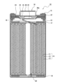
- FIG. 1 is an axial cross-sectional view of a cylindrical secondary battery that is an example of an embodiment
- FIG. 1 is a cross-sectional view of a negative electrode in one example of an embodiment
- FIG. It is a schematic diagram showing a cross section of a graphite particle in an example of the embodiment.
- FIG. 1 is an axial cross-sectional view of a cylindrical secondary battery 10 that is an example of an embodiment.
- an electrode body 14 and a non-aqueous electrolyte (electrolytic solution) are housed in an exterior body 15 .
- the electrode body 14 has a wound structure in which the positive electrode 11 and the negative electrode 12 are wound with the separator 13 interposed therebetween.
- the “winding inner side” means the winding center side of the electrode body 14
- the “winding outer side” means the outer peripheral side of the electrode body 14 .
- the sealing member 16 side will be referred to as "upper”
- the bottom side of the outer package 15 will be referred to as "lower”.
- the inside of the secondary battery 10 is hermetically sealed by closing the opening end of the exterior body 15 with the sealing body 16 .
- Insulating plates 17 and 18 are provided above and below the electrode body 14, respectively.
- the positive electrode lead 19 extends upward through the through hole of the insulating plate 17 and is welded to the lower surface of the filter 22 which is the bottom plate of the sealing member 16 .
- the cap 26, which is the top plate of the sealing member 16 electrically connected to the filter 22, serves as a positive electrode terminal.
- the negative electrode lead 20 passes through the through hole of the insulating plate 18 , extends to the bottom side of the exterior body 15 , and is welded to the bottom inner surface of the exterior body 15 .
- the exterior body 15 becomes a negative electrode terminal.
- the negative lead 20 When the negative lead 20 is installed at the terminal end, the negative lead 20 extends through the outside of the insulating plate 18 toward the bottom of the package 15 and is welded to the inner surface of the bottom of the package 15 .
- the exterior body 15 is, for example, a bottomed cylindrical metal exterior can.
- a gasket 27 is provided between the exterior body 15 and the sealing body 16 to ensure hermetic sealing of the inside of the secondary battery 10 .
- the exterior body 15 has, for example, a grooved portion 21 formed by pressing the side portion from the outside.
- the grooved portion 21 is preferably annularly formed along the circumferential direction of the exterior body 15 and supports the sealing body 16 via a gasket 27 on its upper surface.
- the sealing body 16 has a filter 22, a lower valve body 23, an insulating member 24, an upper valve body 25, and a cap 26, which are stacked in order from the electrode body 14 side.
- Each member constituting the sealing member 16 has, for example, a disk shape or a ring shape, and each member other than the insulating member 24 is electrically connected to each other.
- the lower valve body 23 and the upper valve body 25 are connected to each other at their central portions, and an insulating member 24 is interposed between their peripheral edge portions.
- the positive electrode 11, the negative electrode 12, the separator 13, and the non-aqueous electrolyte that constitute the secondary battery 10, particularly the negative electrode 12, will be described in detail below.
- FIG. 2 is a cross-sectional view of the negative electrode 12 that is an example of an embodiment.
- the negative electrode 12 includes a negative electrode current collector 30 , an inner negative electrode mixture layer 32 formed on the inner surface of the negative electrode current collector 30 , and an outer surface of the negative electrode current collector 30 . and a wound-side negative electrode mixture layer 34 formed.
- the winding inner negative electrode mixture layer 32 has a first negative electrode mixture layer 32 a facing the negative electrode current collector 30 and a second negative electrode mixture layer 32 b facing the positive electrode 11 .
- the winding outer negative electrode mixture layer 34 has a first negative electrode mixture layer 34 a facing the negative electrode current collector 30 and a second negative electrode mixture layer 34 b facing the positive electrode 11 .
- the negative electrode current collector 30 for example, a foil of a metal such as copper that is stable in the potential range of the negative electrode, a film having the metal on the surface layer, or the like is used.
- the thickness of the negative electrode current collector 30 is, for example, 5 ⁇ m to 30 ⁇ m.
- the winding inner negative electrode mixture layer 32 and the winding outer negative electrode mixture layer 34 contain graphite particles 40 as a negative electrode active material.
- the graphite particles 40 include natural graphite and artificial graphite. From the point of view of ease of adjustment of internal porosity, which will be described later, the graphite particles 40 preferably contain artificial graphite.
- FIG. 3 is a schematic diagram showing a cross section of the graphite particles 40.
- the graphite particle 40 has closed voids 42 (hereinafter referred to as internal voids 42) that are not connected from the inside of the particle to the particle surface, and voids that are connected from the inside of the particle to the particle surface. and a gap 44 (hereinafter referred to as an external gap 44).
- the interplanar spacing (d 002 ) between the (002) planes of the graphite particles 40 measured by the X-ray wide-angle diffraction method is, for example, preferably 0.3354 nm or more, more preferably 0.3357 nm or more, and 0.3357 nm or more. It is preferably less than 340 nm, more preferably 0.338 nm or less.
- the crystallite size (Lc(002)) of the graphite particles 40 determined by the X-ray diffraction method is, for example, preferably 5 nm or more, more preferably 10 nm or more, and 300 nm or less. is preferred, and 200 nm or less is more preferred.
- the graphite particles 40 in the present embodiment include graphite particles having an internal porosity of 6% to 20% (hereinafter referred to as graphite particles A) and graphite particles having an internal porosity of 5% or less (hereinafter referred to as graphite particles B). ) and The internal porosity of the graphite particles A may be from 6% to 20%, preferably from 6% to 15%, and more preferably from 6% to 6%, in order to suppress deterioration of rapid charge cycle characteristics. 10%.
- the internal porosity of the graphite particles B may be 5% or less, preferably 0.5% to 5%, more preferably 1% to 5%, in order to suppress deterioration of rapid charge cycle characteristics. 5%.
- the internal porosity of the graphite particles is a two-dimensional value determined from the ratio of the area of the internal voids 42 of the graphite particles to the cross-sectional area of the graphite particles. Then, the internal porosity of the graphite particles is determined by the following procedure.
- ⁇ Method for measuring internal porosity> The cross section of the negative electrode 12 is exposed.
- a method of exposing the cross section for example, there is a method of cutting a part of the negative electrode and processing it with an ion milling device (eg, IM4000PLUS manufactured by Hitachi High-Tech) to expose the cross section of the negative electrode 12 .
- an ion milling device eg, IM4000PLUS manufactured by Hitachi High-Tech
- a backscattered electron image of the cross section of the exposed negative electrode 12 is photographed using a scanning electron microscope. The magnification for capturing the reflected electron image is 3,000 times to 5,000 times.
- the area of the graphite particle cross section refers to the area of the region surrounded by the outer periphery of the graphite particle, that is, the area of the entire cross section of the graphite particle.
- voids with a width of 3 ⁇ m or less may be difficult to distinguish between internal voids and external voids in image analysis. may be Then, from the calculated area of the graphite particle cross section and the area of the internal voids in the graphite particle cross section, the internal porosity of the graphite particle (area of internal voids in the cross section of the graphite particle ⁇ 100/area of the cross section of the graphite particle) is calculated.
- the internal porosity of graphite particles A and B is an average value of 10 graphite particles A and B, respectively.
- Graphite particles A can be produced, for example, as follows. Coke (precursor), which is the main raw material, is pulverized to a predetermined size, aggregated with a binder, and further pressure-molded to produce a block-shaped compact. At this time, the density of the block-shaped compact is, for example, 1.6 g/cm 3 to 1.9 g/cm 3 . Thereafter, this block-shaped compact is fired at a temperature of 2600° C. or higher to graphitize it. Graphite particles A having a desired size are obtained by pulverizing and sieving the block-shaped compact after graphitization. Here, the internal porosity can be adjusted to 6% to 20% by adjusting the amount of volatile components added to the block-shaped compact. If part of the binder added to the coke (precursor) volatilizes during firing, the binder can be used as a volatile component. Pitch is exemplified as such a binder.
- Graphite particles B can be produced, for example, as follows. Coke (precursor), which is the main raw material, is pulverized to a predetermined size, aggregated with a binder, fired at a temperature of 2600 ° C. or higher, graphitized, and sieved to obtain the desired Graphite particles B of size are obtained.
- the internal porosity can be adjusted to 5% or less depending on the particle size of the precursor after pulverization, the particle size of the aggregated precursor, and the like. For example, the internal porosity can be reduced by increasing the particle size of the precursor after pulverization.
- the average particle diameter of the pulverized precursor may be in the range of 12 ⁇ m to 20 ⁇ m.
- the first negative electrode mixture layers 32a and 34a (hereinafter, the first negative electrode mixture layers 32a and 34a may be collectively referred to as first negative electrode mixture layers) contain graphite particles A, and the second negative electrode mixture layers 32a and 34a Graphite particles B are included in mixture layers 32b and 34b (hereinafter, the second anode mixture layers 32b and 34b may be collectively referred to as second anode mixture layers).
- the thickness t1 of the first negative electrode mixture layer 32a and the thickness t2 of the second negative electrode mixture layer 32b satisfy t1/t2 ⁇ 1. As a result, it is possible to achieve both a high capacity and an improvement in rapid charge cycle characteristics.
- the battery capacity can be increased. Further, by making the second negative electrode mixture layer 32b containing the graphite particles B thicker than the first negative electrode mixture layer 32a on the inner side of the winding, it is possible to easily hold the electrolytic solution.
- the first negative electrode mixture layer may contain graphite particles other than the graphite particles A, and the second negative electrode mixture layer may contain graphite particles other than the graphite particles B.
- t1 and t2 preferably satisfy 1/3 ⁇ t1/t2 ⁇ 1, more preferably 1/3 ⁇ t1/t2 ⁇ 9/11.
- the thickness t3 of the first negative electrode mixture layer 34a and the thickness t4 of the second negative electrode mixture layer 34b preferably satisfy 1 ⁇ t3/t4 ⁇ 3.
- the product of t1/t2 and t3/t4 is preferably 1 from the viewpoint of increasing the capacity.
- a method for forming the winding inner negative electrode mixture layer 32 and the winding outer negative electrode mixture layer 34 will be described.
- a negative electrode active material containing graphite particles A, a binder, and a solvent such as water are mixed to prepare a first negative electrode mixture slurry.
- a negative electrode active material containing graphite particles B, a binder, and a solvent such as water are mixed to prepare a second negative electrode mixture slurry.
- the first negative electrode mixture slurry is applied to both surfaces of the negative electrode current collector and dried
- the second negative electrode mixture slurry is applied to both surfaces of the coating film of the first negative electrode mixture slurry and dried.
- the winding inner negative electrode mixture layer 32 and the winding outer negative electrode mixture layer 34 can be formed.
- the first negative electrode mixture slurry is applied and dried, and then the second negative electrode mixture slurry is applied.
- a slurry may be applied.
- the first negative electrode mixture slurry may be applied, dried, and rolled, and then the second negative electrode mixture slurry may be applied on the first negative electrode mixture layer.
- the first negative electrode mixture layer and the second negative electrode mixture layer may contain other negative electrode active materials capable of reversibly intercalating and deintercalating lithium ions in addition to the graphite particles A and B used in the present embodiment.
- at least one of the first negative electrode mixture layer and the second negative electrode mixture layer may contain a Si-based material.
- a Si-based material can occlude more lithium ions than graphite, so the capacity of the battery can be increased.
- Si-based materials include Si, alloys containing Si, Si oxides represented by SiO X (0.5 ⁇ x ⁇ 1.6), and Li 2y SiO (2+y) (0 ⁇ y ⁇ 2).
- Examples include a Si-containing material in which Si fine particles are dispersed in a lithium silicate phase, and a Si-containing material in which Si fine particles are dispersed in a carbon phase.
- the Si-based material preferably contains SiO x (0.5 ⁇ x ⁇ 1.6).
- the ratio of the Si-based material to the total mass of the negative electrode active material is preferably 1 mass from the viewpoint of improving battery capacity, suppressing deterioration in charge-discharge cycle characteristics, and the like. % to 10% by mass, more preferably 3% to 7% by mass.
- the first negative electrode mixture layer and the second negative electrode mixture layer may further contain a binder.
- binders include fluorine resins, polyimide resins, acrylic resins, polyolefin resins, polyacrylonitrile (PAN), styrene-butadiene rubber (SBR), nitrile-butadiene rubber (NBR), carboxymethyl cellulose (CMC ) or salts thereof, polyacrylic acid (PAA) or salts thereof (PAA-Na, PAA-K, etc., and partially neutralized salts may also be used), polyvinyl alcohol (PVA), and the like. These may be used alone or in combination of two or more.
- the first negative electrode mixture layer and the second negative electrode mixture layer may further contain a conductive agent.
- conductive agents include carbon-based particles such as carbon black (CB), acetylene black (AB), ketjen black, carbon nanotubes (CNT), graphene, and graphite. These may be used alone or in combination of two or more.
- the positive electrode 11 is composed of, for example, a positive electrode current collector such as a metal foil, and a positive electrode mixture layer formed on the positive electrode current collector.
- a positive electrode current collector such as a metal foil
- a positive electrode mixture layer formed on the positive electrode current collector.
- the positive electrode current collector a foil of a metal such as aluminum that is stable in the positive electrode potential range, a film having the metal on the surface layer, or the like can be used.
- the positive electrode mixture layer contains, for example, a positive electrode active material, a binder, a conductive agent, and the like.
- a positive electrode mixture slurry containing a positive electrode active material, a binder, a conductive agent, etc. is applied onto a positive electrode current collector and dried to form a positive electrode mixture layer. It can be produced by rolling.
- Examples of positive electrode active materials include lithium transition metal oxides containing transition metal elements such as Co, Mn, and Ni.
- Lithium transition metal oxides include, for example, Li x CoO 2 , Li x NiO 2 , Li x MnO 2 , Li x Co y Ni 1-y O 2 , Li x Co y M 1-y O z , Li x Ni 1- yMyOz , LixMn2O4, LixMn2-yMyO4, LiMPO4 , Li2MPO4F ( M ; Na , Mg , Sc, Y , Mn, Fe, Co, Ni , Cu, Zn, Al, Cr, Pb, Sb, and B, 0 ⁇ x ⁇ 1.2, 0 ⁇ y ⁇ 0.9, 2.0 ⁇ z ⁇ 2.3).
- the positive electrode active material is Li x NiO 2 , Li x Co y Ni 1-y O 2 , Li x Ni 1-y My O z ( M; at least one of Na, Mg, Sc, Y, Mn, Fe, Co, Ni, Cu, Zn, Al, Cr, Pb, Sb, and B, 0 ⁇ x ⁇ 1.2, 0 ⁇ y ⁇ 0 .9, 2.0 ⁇ z ⁇ 2.3).
- Conductive agents include, for example, carbon black (CB), acetylene black (AB), ketjen black, carbon nanotubes (CNT), graphene, and carbon-based particles such as graphite. These may be used alone or in combination of two or more.
- binders include fluorine-based resins such as polytetrafluoroethylene (PTFE) and polyvinylidene fluoride (PVdF), polyimide-based resins, acrylic resins, polyolefin-based resins, and polyacrylonitrile (PAN). These may be used alone or in combination of two or more.
- fluorine-based resins such as polytetrafluoroethylene (PTFE) and polyvinylidene fluoride (PVdF)
- PVdF polyvinylidene fluoride
- acrylic resins acrylic resins
- polyolefin-based resins polyolefin-based resins
- PAN polyacrylonitrile
- separator 13 for example, a porous sheet or the like having ion permeability and insulation is used. Specific examples of porous sheets include microporous thin films, woven fabrics, and non-woven fabrics. Suitable materials for the separator include olefin resins such as polyethylene and polypropylene, and cellulose.
- the separator 13 may be a laminate having a cellulose fiber layer and a thermoplastic resin fiber layer such as an olefin resin. Also, a multilayer separator including a polyethylene layer and a polypropylene layer may be used, and a separator 13 having a surface coated with a material such as aramid resin or ceramic may be used.
- a non-aqueous electrolyte is a liquid electrolyte (electrolytic solution) containing a non-aqueous solvent and an electrolyte salt dissolved in the non-aqueous solvent.
- non-aqueous solvents examples include esters, ethers, nitriles such as acetonitrile, amides such as dimethylformamide, and mixed solvents of two or more thereof.
- the non-aqueous solvent may contain a halogen-substituted product obtained by substituting at least part of the hydrogen atoms of these solvents with halogen atoms such as fluorine.
- esters examples include cyclic carbonates such as ethylene carbonate (EC), propylene carbonate (PC) and butylene carbonate, dimethyl carbonate (DMC), ethyl methyl carbonate (EMC), diethyl carbonate (DEC), methyl propyl carbonate. , Ethyl propyl carbonate, methyl isopropyl carbonate and other chain carbonates, ⁇ -butyrolactone, ⁇ -valerolactone and other cyclic carboxylic acid esters, methyl acetate, ethyl acetate, propyl acetate, methyl propionate (MP), ethyl propionate, etc. and chain carboxylic acid esters of.
- cyclic carbonates such as ethylene carbonate (EC), propylene carbonate (PC) and butylene carbonate, dimethyl carbonate (DMC), ethyl methyl carbonate (EMC), diethyl carbonate (DEC), methyl propyl carbonate.
- ethers examples include 1,3-dioxolane, 4-methyl-1,3-dioxolane, tetrahydrofuran, 2-methyltetrahydrofuran, propylene oxide, 1,2-butylene oxide, 1,3-dioxane, 1,4 -dioxane, 1,3,5-trioxane, furan, 2-methylfuran, 1,8-cineol, cyclic ethers such as crown ether, 1,2-dimethoxyethane, diethyl ether, dipropyl ether, diisopropyl ether, dibutyl ether , dihexyl ether, ethyl vinyl ether, butyl vinyl ether, methyl phenyl ether, ethyl phenyl ether, butyl phenyl ether, pentyl phenyl ether, methoxytoluene, benzyl ethyl ether, diphenyl ether, cycl
- a fluorinated cyclic carbonate such as fluoroethylene carbonate (FEC), a fluorinated chain carbonate, a fluorinated chain carboxylate such as methyl fluoropropionate (FMP), and the like.
- FEC fluoroethylene carbonate
- FMP fluorinated chain carboxylate
- FEC fluoroethylene carbonate
- FMP fluorinated chain carboxylate
- the electrolyte salt is a lithium salt.
- lithium salts include LiBF4 , LiClO4 , LiPF6 , LiAsF6 , LiSbF6 , LiAlCl4 , LiSCN, LiCF3SO3 , LiCF3CO2 , Li(P( C2O4 ) F4 ) , LiPF 6-x (C n F 2n+1 ) x (1 ⁇ x ⁇ 6, n is 1 or 2), LiB 10 Cl 10 , LiCl, LiBr, LiI, lithium chloroborane, lithium lower aliphatic carboxylate, Li 2 B 4O7 , borates such as Li (B( C2O4 ) F2 ), LiN( SO2CF3 ) 2 , LiN( C1F2l + 1SO2 )( CmF2m + 1SO2 ) ⁇ l , where m is an integer of 1 or more ⁇ .
- Lithium salts may be used singly or in combination. Of these, it is preferable to use LiPF 6 from the viewpoint of ion conductivity, electrochemical stability, and the like.
- the lithium salt concentration is preferably 0.8 to 1.8 mol per 1 L of solvent.
- Example 1 [Preparation of positive electrode] A particulate lithium transition metal oxide represented by LiCo 0.979 Zr 0.001 Mg 0.01 Al 0.01 O 2 was used as the positive electrode active material. 95 parts by mass of the positive electrode active material, 2.5 parts by mass of acetylene black (AB) as a conductive agent, and 2.5 parts by mass of polyvinylidene fluoride powder as a binding agent. An appropriate amount of -2-pyrrolidone (NMP) was added to prepare a positive electrode mixture slurry.
- NMP -2-pyrrolidone
- This slurry is applied to both sides of a positive electrode current collector made of aluminum foil (thickness 15 ⁇ m) by a doctor blade method, the coating film is dried, and then the coating film is rolled with a rolling roller to A positive electrode having a positive electrode mixture layer formed thereon was produced.
- Graphite particles A and SiO were mixed at a mass ratio of 95:5 to obtain a first negative electrode active material.
- 100 parts by mass of the first negative electrode active material, 1 part by mass of carboxymethyl cellulose (CMC), and 1 part by mass of styrene-butadiene copolymer rubber (SBR) are mixed, and the mixture is kneaded in water, A first negative electrode mixture slurry was prepared.
- a second negative electrode active material was prepared by mixing graphite particles B and SiO at a mass ratio of 95:5. 100 parts by mass of the second negative electrode active material, 1 part by mass of CMC, and 1 part by mass of SBR were mixed, and the mixture was kneaded in water to prepare a second negative electrode mixture slurry.
- the first negative electrode mixture slurry was applied to both sides of a negative electrode current collector made of copper foil by a doctor blade method and dried to form a first negative electrode mixture layer. Furthermore, the second negative electrode mixture slurry was applied onto the first negative electrode mixture layer and dried to form a second negative electrode mixture layer. At this time, the coating mass ratio per unit area of the first negative electrode mixture slurry and the second negative electrode mixture slurry was 45:55 on the inner side of the winding and 55:45 on the outer side of the winding. The total amount of coating mass per unit area of the first negative electrode mixture slurry and the second negative electrode mixture slurry was made substantially the same between the inner side and the outer side of the winding.
- a negative electrode was produced by rolling the first negative electrode mixture layer and the second negative electrode mixture layer with a rolling roller. After rolling, t1/t2 was 9/11 and t3/t4 was 11/9. Further, when the internal porosities of graphite particles A and graphite particles B were measured in the produced negative electrode, they were 8% and 3%, respectively.
- Non-aqueous electrolyte secondary battery (1) After attaching the positive electrode lead to the positive electrode current collector and attaching the negative electrode lead to the negative electrode current collector, the positive electrode and the negative electrode are wound with a separator made of a polyethylene microporous film interposed therebetween to form a winding type. An electrode body was produced. (2) Insulating plates were placed above and below the electrode body, the negative electrode lead was welded to the case body, the positive electrode lead was welded to the sealing body, and the electrode body was housed in the case body. (3) After injecting the non-aqueous electrolyte into the case main body by a depressurization method, the opening of the case main body was sealed with a sealing member via a gasket. This was used as a non-aqueous electrolyte secondary battery.
- Example 2 Except that in the preparation of the negative electrode, the coating weight ratio per unit area of the first negative electrode mixture slurry and the second negative electrode mixture slurry was adjusted to 40:60 on the inner side of the winding and 60:40 on the outer side of the winding. prepared a test cell in the same manner as in Example 1. After rolling, t1/t2 was 2/3 and t3/t4 was 3/2.
- Example 3 Except that in the preparation of the negative electrode, the coating weight ratio per unit area of the first negative electrode mixture slurry and the second negative electrode mixture slurry was adjusted to be 30:70 on the inner side of the winding and 70:30 on the outer side of the winding. prepared a test cell in the same manner as in Example 1. After rolling, t1/t2 was 3/7 and t3/t4 was 7/3.
- Example 4 Except that in the preparation of the negative electrode, the coating weight ratio per unit area of the first negative electrode mixture slurry and the second negative electrode mixture slurry was adjusted to 25:75 on the inner side of the winding and 75:25 on the outer side of the winding. prepared a test cell in the same manner as in Example 1. After rolling, t1/t2 was 1/3 and t3/t4 was 3.
- Example 5 Except that in the preparation of the negative electrode, the coating weight ratio per unit area of the first negative electrode mixture slurry and the second negative electrode mixture slurry was adjusted to 40:60 on the inner side of the winding and 50:50 on the outer side of the winding. prepared a test cell in the same manner as in Example 1. After rolling, t1/t2 was 2/3 and t3/t4 was 1.
- Example 2 except that in the preparation of the negative electrode, the coating mass ratio per unit area of the first negative electrode mixture slurry and the second negative electrode mixture slurry was adjusted to be 50:50 on the inner side and the outer side of the winding.
- a test cell was prepared in the same manner as in 1. Both t1/t2 and t3/t4 were 1 after rolling.
- Capacity retention rate (discharge capacity at 300th cycle/discharge capacity at 1st cycle) x 100
- Table 1 summarizes the evaluation results of the capacity retention rate of the test cells of each example and each comparative example. Table 1 also shows the internal porosity of the graphite particles contained in the first negative electrode mixture layer and the second negative electrode mixture layer, and the first and second negative electrode mixture layers on the inner side and the outer side of the winding. and thickness ratios (t1/t2, t3/t4) are also shown.
- the battery of the example has an improved capacity retention rate compared to the battery of the comparative example.
- the negative electrode mixture layers having a predetermined structure were formed on the inner side and the outer side of the winding of the negative electrode current collector. improved. From the viewpoint of battery capacity, Examples 1 to 4 are more preferable than Example 5.
Landscapes
- Chemical & Material Sciences (AREA)
- Chemical Kinetics & Catalysis (AREA)
- Electrochemistry (AREA)
- General Chemical & Material Sciences (AREA)
- Composite Materials (AREA)
- Engineering & Computer Science (AREA)
- Manufacturing & Machinery (AREA)
- Inorganic Chemistry (AREA)
- Battery Electrode And Active Subsutance (AREA)
- Secondary Cells (AREA)
Priority Applications (4)
| Application Number | Priority Date | Filing Date | Title |
|---|---|---|---|
| JP2024501330A JPWO2023157746A1 (https=) | 2022-02-15 | 2023-02-09 | |
| US18/836,877 US20250038207A1 (en) | 2022-02-15 | 2023-02-09 | Non-aqueous electrolyte secondary battery |
| CN202380020532.9A CN118679596A (zh) | 2022-02-15 | 2023-02-09 | 非水电解质二次电池 |
| EP23756272.3A EP4481845A4 (en) | 2022-02-15 | 2023-02-09 | NON-AQUEOUS ELECTROLYTE SECONDARY BATTERY |
Applications Claiming Priority (2)
| Application Number | Priority Date | Filing Date | Title |
|---|---|---|---|
| JP2022-021097 | 2022-02-15 | ||
| JP2022021097 | 2022-02-15 |
Publications (1)
| Publication Number | Publication Date |
|---|---|
| WO2023157746A1 true WO2023157746A1 (ja) | 2023-08-24 |
Family
ID=87578170
Family Applications (1)
| Application Number | Title | Priority Date | Filing Date |
|---|---|---|---|
| PCT/JP2023/004312 Ceased WO2023157746A1 (ja) | 2022-02-15 | 2023-02-09 | 非水電解質二次電池 |
Country Status (5)
| Country | Link |
|---|---|
| US (1) | US20250038207A1 (https=) |
| EP (1) | EP4481845A4 (https=) |
| JP (1) | JPWO2023157746A1 (https=) |
| CN (1) | CN118679596A (https=) |
| WO (1) | WO2023157746A1 (https=) |
Cited By (1)
| Publication number | Priority date | Publication date | Assignee | Title |
|---|---|---|---|---|
| WO2025164418A1 (ja) * | 2024-01-31 | 2025-08-07 | パナソニックIpマネジメント株式会社 | 負極および電池 |
Citations (5)
| Publication number | Priority date | Publication date | Assignee | Title |
|---|---|---|---|---|
| WO2019187537A1 (ja) * | 2018-03-30 | 2019-10-03 | パナソニック株式会社 | 非水電解質二次電池用負極及び非水電解質二次電池 |
| WO2019239652A1 (ja) | 2018-06-15 | 2019-12-19 | 三洋電機株式会社 | 非水電解質二次電池 |
| WO2020044930A1 (ja) * | 2018-08-29 | 2020-03-05 | パナソニックIpマネジメント株式会社 | 非水電解質二次電池 |
| WO2021106730A1 (ja) * | 2019-11-27 | 2021-06-03 | 三洋電機株式会社 | 非水電解質二次電池 |
| WO2021117550A1 (ja) * | 2019-12-13 | 2021-06-17 | パナソニックIpマネジメント株式会社 | 非水電解液二次電池 |
-
2023
- 2023-02-09 US US18/836,877 patent/US20250038207A1/en active Pending
- 2023-02-09 JP JP2024501330A patent/JPWO2023157746A1/ja active Pending
- 2023-02-09 CN CN202380020532.9A patent/CN118679596A/zh active Pending
- 2023-02-09 WO PCT/JP2023/004312 patent/WO2023157746A1/ja not_active Ceased
- 2023-02-09 EP EP23756272.3A patent/EP4481845A4/en active Pending
Patent Citations (5)
| Publication number | Priority date | Publication date | Assignee | Title |
|---|---|---|---|---|
| WO2019187537A1 (ja) * | 2018-03-30 | 2019-10-03 | パナソニック株式会社 | 非水電解質二次電池用負極及び非水電解質二次電池 |
| WO2019239652A1 (ja) | 2018-06-15 | 2019-12-19 | 三洋電機株式会社 | 非水電解質二次電池 |
| WO2020044930A1 (ja) * | 2018-08-29 | 2020-03-05 | パナソニックIpマネジメント株式会社 | 非水電解質二次電池 |
| WO2021106730A1 (ja) * | 2019-11-27 | 2021-06-03 | 三洋電機株式会社 | 非水電解質二次電池 |
| WO2021117550A1 (ja) * | 2019-12-13 | 2021-06-17 | パナソニックIpマネジメント株式会社 | 非水電解液二次電池 |
Non-Patent Citations (1)
| Title |
|---|
| See also references of EP4481845A4 |
Cited By (1)
| Publication number | Priority date | Publication date | Assignee | Title |
|---|---|---|---|---|
| WO2025164418A1 (ja) * | 2024-01-31 | 2025-08-07 | パナソニックIpマネジメント株式会社 | 負極および電池 |
Also Published As
| Publication number | Publication date |
|---|---|
| CN118679596A (zh) | 2024-09-20 |
| EP4481845A4 (en) | 2025-07-23 |
| EP4481845A1 (en) | 2024-12-25 |
| US20250038207A1 (en) | 2025-01-30 |
| JPWO2023157746A1 (https=) | 2023-08-24 |
Similar Documents
| Publication | Publication Date | Title |
|---|---|---|
| JP7319265B2 (ja) | 非水電解質二次電池 | |
| JPWO2020175361A1 (ja) | 非水電解質二次電池 | |
| JP7336736B2 (ja) | 非水電解質二次電池 | |
| JP7233013B2 (ja) | 非水電解質二次電池 | |
| WO2022181489A1 (ja) | 非水電解質二次電池用負極及び非水電解質二次電池 | |
| JP7808762B2 (ja) | 二次電池用負極及び二次電池 | |
| WO2023171564A1 (ja) | 非水電解液二次電池 | |
| WO2021117480A1 (ja) | 非水電解液二次電池 | |
| JP7682099B2 (ja) | 非水電解質二次電池 | |
| WO2021117748A1 (ja) | 非水電解質二次電池 | |
| WO2021111930A1 (ja) | 非水電解液二次電池 | |
| JP7738484B2 (ja) | 非水電解質二次電池 | |
| WO2023157746A1 (ja) | 非水電解質二次電池 | |
| JP7783200B2 (ja) | 非水電解質二次電池 | |
| JP7814013B2 (ja) | 非水電解質二次電池用正極活物質、及び非水電解質二次電池 | |
| JP7665440B2 (ja) | 非水電解質二次電池 | |
| WO2023149529A1 (ja) | 非水電解質二次電池 | |
| WO2023276582A1 (ja) | 非水電解質二次電池 | |
| JP7646562B2 (ja) | 非水電解質二次電池用負極、非水電解質二次電池、及び非水電解質二次電池用負極の製造方法 | |
| WO2022190852A1 (ja) | 非水電解質二次電池 | |
| JP7638280B2 (ja) | 非水電解質二次電池用負極及び非水電解質二次電池 | |
| JP7814014B2 (ja) | 非水電解質二次電池用正極活物質、及び非水電解質二次電池 | |
| US20250372625A1 (en) | Negative electrode for nonaqueous electrolyte secondary batteries, and nonaqueous electrolyte secondary battery | |
| JP7713646B2 (ja) | 非水電解質二次電池用正極活物質、及び非水電解質二次電池 | |
| WO2024004836A1 (ja) | 非水電解質二次電池 |
Legal Events
| Date | Code | Title | Description |
|---|---|---|---|
| 121 | Ep: the epo has been informed by wipo that ep was designated in this application |
Ref document number: 23756272 Country of ref document: EP Kind code of ref document: A1 |
|
| ENP | Entry into the national phase |
Ref document number: 2024501330 Country of ref document: JP Kind code of ref document: A |
|
| WWE | Wipo information: entry into national phase |
Ref document number: 202380020532.9 Country of ref document: CN |
|
| WWE | Wipo information: entry into national phase |
Ref document number: 18836877 Country of ref document: US |
|
| WWE | Wipo information: entry into national phase |
Ref document number: 202447060281 Country of ref document: IN |
|
| WWE | Wipo information: entry into national phase |
Ref document number: 2023756272 Country of ref document: EP |
|
| NENP | Non-entry into the national phase |
Ref country code: DE |
|
| ENP | Entry into the national phase |
Ref document number: 2023756272 Country of ref document: EP Effective date: 20240916 |