WO2023157279A1 - クレーン装置、クレーン装置制御方法及び端部装置 - Google Patents
クレーン装置、クレーン装置制御方法及び端部装置 Download PDFInfo
- Publication number
- WO2023157279A1 WO2023157279A1 PCT/JP2022/006875 JP2022006875W WO2023157279A1 WO 2023157279 A1 WO2023157279 A1 WO 2023157279A1 JP 2022006875 W JP2022006875 W JP 2022006875W WO 2023157279 A1 WO2023157279 A1 WO 2023157279A1
- Authority
- WO
- WIPO (PCT)
- Prior art keywords
- hoisting
- hollow interior
- wire rope
- ground
- support
- Prior art date
- Legal status (The legal status is an assumption and is not a legal conclusion. Google has not performed a legal analysis and makes no representation as to the accuracy of the status listed.)
- Ceased
Links
Images



Classifications
-
- B—PERFORMING OPERATIONS; TRANSPORTING
- B66—HOISTING; LIFTING; HAULING
- B66C—CRANES; LOAD-ENGAGING ELEMENTS OR DEVICES FOR CRANES, CAPSTANS, WINCHES, OR TACKLES
- B66C13/00—Other constructional features or details
- B66C13/16—Applications of indicating, registering, or weighing devices
-
- B—PERFORMING OPERATIONS; TRANSPORTING
- B66—HOISTING; LIFTING; HAULING
- B66C—CRANES; LOAD-ENGAGING ELEMENTS OR DEVICES FOR CRANES, CAPSTANS, WINCHES, OR TACKLES
- B66C15/00—Safety gear
Definitions
- the present invention relates to a crane device, a crane device control method, and an end device.
- the suspended load, etc. may fall or pinch pressure due to the suspended load, etc. may occur.
- an empty load a state where there is no suspended load (hereinafter referred to as an empty load)
- a hoisting operation is performed with a hacker attached to the hook of the crane device, and the hacker or the like is caught in the load during the hoisting operation. Even with this, there is a risk that the suspended load or the like may fall or collapse. Therefore, it is required to improve the safety of the hoisting operation of a suspended load or the like and the hoisting operation with no load.
- the present invention has the following configuration.
- a hoisting device capable of hoisting and lowering a wire rope for hoisting a load; driving means for driving the hoisting device; Ground breaking detection means for detecting a ground breaking of the suspended load; an operation unit for operating the hoisting device; a control means for controlling the drive means based on the operation by the operation section and the detection result of the ground breaking detection means; with The control means stops the hoisting operation until a predetermined time elapses when the ground-off detection means detects a ground-off after the hoisting device starts the hoisting operation.
- a crane device that controls a vehicle.
- a crane device control method for controlling the crane device according to (1) A hoisting step of starting a hoisting operation by the hoisting device; a detection step of detecting a ground break by the ground break detection means; a stopping step of stopping the hoisting operation until a predetermined time elapses when ground breaking is detected in the detecting step; is executed by the control means.
- An end device attached to the end of a wire rope for lifting a load having an outer cylinder, a support, and an elastic member
- the outer cylindrical portion has a substantially cylindrical shape with a hollow interior
- the support portion has a substantially cylindrical shape with a hollow interior, and is disposed slidably in the hollow interior of the outer cylindrical portion
- the elastic member expands and contracts as the support portion slides in the hollow interior of the outer cylinder portion, thereby generating a biasing force that restores the position of the support portion with respect to the outer cylinder portion to a predetermined position
- An end device wherein the support slides along with the end of the wire rope in the hollow interior of the outer cylinder when the end of the wire rope is fixed in the hollow interior of the support.
- the present invention it is possible to provide a crane device, a crane device control method, and an end device that can improve the safety of the hoisting operation of the crane device.
- the crane device of this embodiment is used at work sites such as factories, construction work sites, container terminals, and the like.
- Worksites may also include warehouses, such as locations where cargo is stored for a period of time, and intermediate warehouses where cargo is temporarily stored.
- An object that is lifted or suspended by a crane device is called a load or load.
- the vertical direction in which the load is lifted or suspended is also called the lifting direction (z direction).
- the traveling direction (x direction) of the saddle of the overhead crane and the traveling direction of the club of the overhead crane (hereinafter referred to as the transverse direction (y direction) ) is a direction substantially orthogonal to the elevation direction.
- FIG. 1 is a schematic perspective view showing the configuration of the main part of the crane device 100 of the present embodiment, and also shows the lifting direction.
- the crane device 100 is a device for lifting and transporting a load (not shown) at a work site.
- the crane device 100 may be a crane device having various configurations such as an overhead crane.
- the crane device 100 has a hoisting device 110 , a control section 120 as control means, a drive section 130 as drive means, an operation section 180 , a wire end fixing section 200 and a ground breaking sensor 300 .
- a wire rope 140, a hook unit 150, a sling wire 160, and a hacker 170 are also used to lift the load.
- the hoisting device 110 has a hoisting drum 112 .
- the hoisting drum 112 is a rotating body capable of hoisting and lowering a wire rope 140 for hoisting a load (white arrow in the figure).
- the hoisting drum 112 is connected to the motor of the driving section 130 and is capable of forward and reverse rotation as indicated by the double arrow in the figure based on the control command from the control section 120 .
- One end of a wire rope 140 (a starting end, hereinafter also referred to as a leading end 142 ) is fixed to the hoisting drum 112 .
- the hoisting device 110 is hoisted when lifting a suspended load placed on the floor surface (not shown) of the work site.
- the hoisting device 110 moves with the load suspended by the crane device 100, and is hoisted when the load is unloaded onto a floor surface, a loading platform of a vehicle, or the like at a predetermined location.
- the hoisting device 110 also hoists the hacker 170 or the like to a predetermined height or higher in a state where there is no suspended load (hereinafter referred to as an empty load), such as after the crane device 100 has unloaded the suspended load. be done.
- a hook unit 150 for hanging a slinging wire 160 is tethered to the wire rope 140 .
- the hook unit 150 has a hook portion 152 for hooking the slinging wire 160 and a sheave 154 for mooring the hook unit 150 to the wire rope 140 .
- a wire rope 140 is wound around the sheave 154 .
- a hacker 170 is movably attached to the sling wire 160.
- a pair of hackers 170a and 170b are attached so as to face each other.
- the slinging wire 160 and the hacker 170 may not be used, and the load may be directly hung on the hook portion 152 .
- the other end of the wire rope 140 (end, hereinafter also referred to as rear end 144) is fixed by a wire end fixing part 200 to a fixed part 195 such as the ceiling of the work site or the club of an overhead crane.
- the operation unit 180 is, for example, a controller device operated by a worker who operates the crane device 100 (hereinafter referred to as an operator), and is used when operating the crane device 100 .
- the operation unit 180 is, for example, a wireless (eg, teleconverter) or wired (eg, pendant) controller device.
- FIG. 1 shows a wireless type operation unit 180 .
- the operation unit 180 has an upper button 182 and a lower button 184, for example.
- the controller 120 causes the hoisting drum 112 to hoist the wire rope 140 and move the hook unit 150 upward.
- the upper button 182 is used, for example, when lifting (raising) a suspended load or when retracting upward the hook unit 150 that has become empty.
- the controller 120 causes the hoisting drum 112 to lower the wire rope 140 and move the hook unit 150 downward.
- the lower button 184 is used, for example, when lowering a suspended load or when lowering an empty hook unit 150 .
- the operation unit 180 may have other buttons for horizontally moving the crane device 100, for example, north, south, east, west, left, right, front and back.
- the operation unit 180 also includes a start button for transmitting to the control unit 120 that the control of the crane device 100 is to be started, an end button for transmitting to the control unit 120 that the control of the crane device 100 is to be terminated, It may further have a lock button or the like for prohibiting button operation.
- the operation unit 180 may be, for example, a known input means (not shown) such as a keyboard and a mouse.
- the operation unit 180 may be one that controls the target (in this case, the crane device 100) by voice recognition such as a microphone, or one that controls the target by a line-of-sight tracking device.
- the crane device 100 may include a display (not shown) such as a display that displays the state of the crane device 100 .
- the control unit 120 controls various operations of the crane device 100 .
- the control unit 120 has, for example, a CPU, a ROM, a RAM, a timer, and the like.
- the control unit 120 controls the crane apparatus 100 by performing various calculations with the CPU while using the RAM as a temporary work area according to various programs stored in the ROM and monitoring various timings with a timer.
- the drive unit 130 has known drive means and transmission means (not shown) such as a motor, cylinder, clutch, and gear for driving the hoisting drum 112 .
- Drive unit 130 is controlled to start (hereinafter also referred to as ON) and stop (hereinafter also referred to as OFF) driving of the motor according to the drive signal output from control unit 120 .
- ON start
- stop stop
- the drive unit 130 stops driving without delay when a stop drive signal is transmitted from the control unit 120 .
- the drive unit 130 requires a period of time corresponding to the characteristics (inertia) of the motor used to completely stop after a stop drive signal is transmitted from the control unit 120 .
- the wire end fixing portion 200 and the ground breaking sensor 300 will be described later.
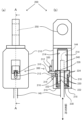
- FIG. 2(a) is a front view showing the wire end fixing portion 200 of the present embodiment
- FIG. 2(b) is a cross-sectional view taken along the line AA of (a).
- FIG. 2 also shows the extending direction of the wire rope 140 .
- the extension direction of the wire rope 140 is the direction in which the wire rope 140 extends or the direction along the wire rope 140, and the wire rope 140 is moved by the hoisting operation or the hoisting operation of the hoisting drum 112. It can also be said to be the direction of movement.
- the wire end fixing portion 200 has a casing 210 that is an outer cylindrical portion, a support portion 220, a coil spring 230 that is an elastic member, and a hook portion 250.
- Casing 210 has a substantially cylindrical shape with a hollow interior.
- the casing 210 has an elongated hole portion 212 and an inner wall portion 214 .
- the long hole portion 212 is a hole through which a later-described projecting portion 310 of the ground breaking sensor 300 attached to the casing 210 penetrates.
- the inner wall portion 214 forms a space (hollow interior) in which the rear end 144 of the wire rope 140, the support portion 220, and the coil spring 230 are accommodated.
- the hollow interior of the casing 210 is not limited to a substantially cylindrical shape as long as the rear end 144 of the wire rope 140, the support portion 220, and the coil spring 230 can slide.
- the inner wall portion 214 has a stopper 216 as a restricting portion and a flange portion 218 as an inner flange portion.
- Stopper 216 is provided in a part of the hollow interior of casing 210 to restrict the sliding range in the extension direction of support portion 220 .
- the stopper 216 abuts on a later-described flange portion 224 of the support portion 220 so that the coil spring 230 is not further compressed when the coil spring 230 is compressed.
- the stopper 216 has been described as a lower stopper that restricts the downward movement of the flange portion 224 to be described later, the stopper 216 is not limited to this.
- the stopper may restrict the sliding range in the extension direction of the support portion 220, and may be an upper stopper that restricts the upward movement of the support portion 220.
- the flange portion 218 protrudes inward from a portion of the hollow interior of the casing 210 .
- the flange portion 218 restricts downward movement of the coil spring 230 when the coil spring 230 is compressed.
- the space formed by the inner wall portion 214 is sized to accommodate at least the support portion 220, the coil spring 230, and the caulking portion 240, which will be described later.
- the hook portion 250 is an opening for fixing the wire end fixing portion 200 to the fixed portion 195 with a metal fitting or the like.
- the support part 220 has a substantially cylindrical shape with a hollow interior, and is arranged slidably inside the hollow interior of the casing 210 .
- the support portion 220 has an inner wall portion 222 , a flange portion 224 that is an outer flange portion, and a fitting portion 226 .
- the inner wall portion 222 forms a space (hollow interior) into which the wire rope 140 is inserted.
- the hollow interior of the support portion 220 is not limited to a substantially cylindrical shape as long as the rear end 144 of the wire rope 140 can be inserted therethrough.
- the space formed by the inner wall portion 222 is sized to accommodate at least the wire rope 140 .
- the flange portion 224 protrudes outward from a portion of the cylindrical outer side of the support portion 220 .
- the flange portion 224 has a diameter that is at least larger than the outer diameter of the coil spring 230, so that when the support portion 220 is inserted into the inner diameter of the coil spring 230, the coil spring 230 does not come off from the flange portion 224 side. It's like
- the support part 220 is inserted into the inner diameter of the coil spring 230 from the side opposite to the side where the flange part 224 is provided. As a result, the coil spring 230 abuts against the flange portion 224 . In this state, the rear end 144 of the wire rope 140 is inserted into the space formed by the inner diameter of the coil spring 230 and the inner wall portion 222 of the support portion 220 from the side opposite to the side on which the flange portion 224 is provided. be done. That is, the wire rope 140 is inserted through the coil spring 230 and the support portion 220 .
- the support part 220 slides inside the hollow inside of the casing 210 together with the end of the wire rope 140 .
- Coil spring 230 expands and contracts as support portion 220 slides in the hollow interior of casing 210 .
- the coil spring 230 generates a biasing force that restores the position of the support portion 220 with respect to the casing 210 to a predetermined position (home position, which will be described later).
- the wire rope 140 inserted through the coil spring 230 and the support portion 220 has a rear end 144 pulled out from the side of the flange portion 224, and is compressed by, for example, a metal fitting such as an aluminum alloy by, for example, compression stopping processing (also referred to as locking processing). be done.
- the rear end 144 of the wire rope 140 is terminal-treated to form the crimped portion 240 .
- the crimped portion 240 , the support portion 220 , the coil spring 230 and the wire rope 140 combined in this way are housed in the space inside the inner wall portion 214 of the casing 210 .
- the coil spring 230 is arranged in the hollow inside of the casing 210 so as to be sandwiched between the flange portion 224 and the flange portion 218 .
- the outer diameter, center diameter, inner diameter, single wire diameter, pitch, degree of freedom, etc. of the coil spring 230 may be determined according to the specifications of the crane device 100, the weight of the load to be transported, and the like.
- the elastic member described above is not limited to the coil spring 230, and may be, for example, a leaf spring, an air spring, a tension spring, or the like.
- the elastic member may be compressed while the wire rope 140 is under tension and restored when the tension is removed. Further, whether each flange portion of the casing 210 or the support portion 220 protrudes outward or inward is a matter of design that differs depending on the shape of the part.
- the fitting portion 226 is a hole into which the fitting portion 314 of the projecting portion 310 of the ground breaking sensor 300 is fitted.
- the support portion 220 is a fitting portion between the long hole portion 212 of the casing 210 and the support portion 220 .
- 226 are stored in the same direction.
- the protruding portion 310 of the ground breaking sensor 300 is fitted into the fitting portion 226 of the support portion 220 via the long hole portion 212, and the protruding portion 310 moves the wire rope 140, in other words, slides the support portion 220. It is possible to move in the extension direction in conjunction with.
- the projecting part 310 moves in conjunction with the movement of the wire rope 140, thereby exhibiting the function as the ground breaking sensor 300.
- a ground breaking sensor 300 which is a ground breaking detection means, is a sensor for detecting a ground breaking of a suspended load, and in this embodiment, for example, a limit switch and a detection dog are used.
- the ground breaking sensor 300 is attached to the casing 210 of the wire end fixing portion 200, and is arranged at a position where the ground breaking can be detected by the movement of the support portion 220 along with the movement along the extension direction of the wire rope 140. ing.
- the ground breaking sensor 300 has a projecting portion 310 and a switch portion 320 .
- the projecting portion 310 has a contact portion 312 and a fitting portion 314 .
- the contact portion 312 is provided at a position where it contacts the switch portion 320 when the wire rope 140 is not under load. A signal is output to the control unit 120 .
- the ground breaking sensor 300 outputs an OFF signal to the control portion 120, for example.
- the fitting portion 314 fits into the fitting portion 226 of the support portion 220 . This allows the projecting portion 310 to move in conjunction with the movement of the support portion 220 .
- the contact portion 312 of the projecting portion 310 contacts the switch portion 320 in a state in which the load is not hung or caught on the wire rope 140, and the ground breaking sensor 300 is in a state of outputting an ON signal.
- the contact portion 312 of the projecting portion 310 is separated from the switch portion 320 in a state where the suspended load is suspended or caught on the wire rope 140, and the ground breaking sensor 300 is in a state of outputting an OFF signal. .
- ground breaking means the moment or before or after the suspended load is lifted from the ground (or ground surface) and separated from the ground, but in this embodiment, “detecting the ground breaking” , means to detect the situation near or just before the ground breaking. That is, the suspended load is in contact with the ground, but it is immediately before or about to leave the ground. It means detecting situations that occur and situations in which one part of the load has left the ground while another part is still in contact with the ground. In other words, the ground breaking sensor 300 detects a situation where at least part of the suspended load is still in contact with the ground and is restrained by the ground and does not swing, but the wire rope 140 is under tension and is not slack. .
- the contact portion 312 of the ground breaking sensor 300 is in contact with the switch portion 320, and the ground breaking sensor 300 outputs an ON signal. do.
- the control unit 120 can determine whether the load has been lifted from the ground based on the output signal from the ground-off sensor 300 .
- the ground breaking sensor 300 is arranged in the casing 210 of the wire end fixing part 200, and the ground breaking of the suspended load can be detected according to the tension of the wire rope 140, but this is not the only option. not.
- the ground breaking sensor 300 does not necessarily have to be arranged in the wire end fixing portion 200, and it is sufficient if the logic of the output signal is inverted according to the movement along the extension direction of the wire rope 140.
- a strain sensor that detects the tension of the wire rope 140 itself can be used as the ground breaking sensor.
- the ground breaking sensor 300 is not necessarily a limit switch, and may be an optical sensor such as a photointerrupter, a magnetic sensor, or other detection device.
- the ground breaking sensor 300 since the ground breaking sensor 300 has a function of detecting the positional relationship between the casing 210 and the support section 220, it can also be said that it is a position detection section.
- This position detection section may be provided on either the casing 210 or the support section 220 of the wire end fixing section 200 as means for detecting the relative position between the casing 210 and the support section 220 .
- Ground breaking detection can also be said to be positional relationship detection, and includes relative position detection or sliding distance detection.
- the ground breaking sensor 300 as a position detection section detects whether the position of the support section 220 with respect to the casing 210 is greater than or equal to a predetermined positional relationship or less than a predetermined positional relationship.
- the ground breaking sensor 300 as a position detection section detects that the sliding distance of the support section 220 with respect to the casing 210 has become equal to or greater than a predetermined distance.
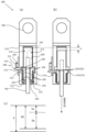
- FIG. 3A and 3B are diagrams illustrating the stroke of the coil spring 230.
- FIG. 3A is a schematic cross-sectional view showing the wire end fixing portion 200 when no load is applied to the wire rope 140
- FIG. 3B is a schematic cross-sectional view showing the stroke.
- FIG. (c) is a schematic diagram for explaining a stroke.
- FIG. 3(b) some reference numerals and lead lines are omitted to make the drawing easier to see.
- FIG. 3 also shows the extending direction of the wire rope 140 .
- the state of FIG. 3A is a state in which the weight of the wire rope 140, the hook unit 150, etc.
- a state in which the support portion 220 is positioned relative to the casing 210 at a predetermined position as shown in FIG. 3A is also called a home position state.
- the stroke S shown in FIG. 3(b) is a stroke.
- the stroke S is the length of movement of the support portion 220 (or the wire rope 140) from the home position in which no load is applied to the wire rope 140 until the flange portion 224 of the support portion 220 hits the stopper 216. (distance).
- the stroke S includes the length determined by the ground breaking sensor 300 (hereinafter referred to as stroke Sa) and the length determined by the inertia of the drive unit 130 (hereinafter referred to as stroke Sb) (S>Sa+Sb).
- the stroke Sa by the ground breaking sensor 300 is the movement distance when the projecting portion 310 is separated from the switch portion 320 when detecting the ground breaking described above, in other words, the wire rope when detecting the ground breaking. 140 movement distance.
- the stroke Sb is provided to absorb the inertia of the driving section 130.
- the drive unit 130 does not stop at the timing when the control unit 120 transmits the stop drive signal to the drive unit 130, and until the drive unit 130 completely stops, the characteristics of the motor used, etc. It takes time according to That is, the hoisting drum 112 maintains the hoisting operation even after the drive signal for stopping is output from the control unit 120 . Since the wire rope 140 is hoisted during this time, the hook unit 150 rises.
- the coil spring 230 of the wire end fixing portion 200 absorbs the distance that the wire rope 140 moves when it is wound up, in other words, it moves within the range of the stroke Sb. are preventing.
- the hook unit 150 is not affected by the inertia of the drive section 130 and the stop drive signal is output from the time when the control section 120 outputs the stop drive signal until the drive section 130 stops. It is possible to maintain the height.
- the stroke Sb may be designed based on the characteristics of the drive unit 130, the characteristics of the coil spring 230, and the like.
- FIG. 4 is a block diagram of the crane device 100 of this embodiment.
- the control unit 120 controls the crane device 100 according to operations input from the operation unit 180 . Also, the control unit 120 controls the crane device 100 based on the detection result of the ground breaking sensor 300 .
- the control unit 120 stores information of a stop after ground-off flag, which will be described later, in the storage unit 190 , and accesses the storage unit 190 to read the information of the stop-after-ground-off flag stored in the storage unit 190 .
- the control unit 120 controls the reset, start, stop, etc. of the timer 192 and uses the timer 192 to control various timings.
- the control unit 120 outputs a drive signal to the drive unit 130 and controls the start, acceleration/deceleration, stop, normal rotation, reverse rotation, etc. of the drive unit 130 .
- the storage unit 190 is the above-described RAM and the timer 192 is the above-described timer, the storage unit 190 and the timer 192 may be included in the control unit 120 .
- the operating unit 180 is operated by an operator and transmits operated information (input information) to the control unit 120 .
- the ground breaking sensor 300 transmits an ON signal or an OFF signal to the control unit 120 according to the ground breaking detection result.
- the storage unit 190 is, for example, the above-described RAM or the like, and can store and read information.
- the timer 192 is referred to by the controller 120 when the controller 120 controls the crane device 100 .
- the driving section 130 drives the winding drum 112 according to the driving signal output from the control section 120 .
- the crane apparatus 100 of the present embodiment stops the hoisting operation and disables the operation by the operation unit 180 when the ground breaking sensor 300 detects the ground breaking after starting the hoisting operation. After a predetermined period of time has elapsed, the operation by the operation unit 180 is enabled, and the hoisting operation can be restarted. Since the control unit 120 disables the operation by the operation unit 180 for at least a predetermined time, even if the operator performs an inching operation by using the operation unit 180, the hoisting drum 112 does not rotate. That is, inching operation can be prevented.
- the predetermined time may be determined according to the time required for confirmation work by the operator, which will be described later.
- the operator is asked to confirm the degree of hooking of the wire rope 140 and the hacker 170 within a predetermined time period during which the hoisting operation is stopped. can be done.
- the operator can confirm within a predetermined time whether the suspended load and the crane device 100 are aligned (the center of gravity), and whether or not a foreign object is caught between the suspended load and the wire rope 140. can be done.
- the operator should be informed that the hoisting tools such as the sling wire 160 and the hacker 170 have interfered with other loads that are not originally intended to be hoisted. can be done. Since the hoisting operation is temporarily stopped, the operator can remove the load erroneously caught on the sling wire 160, the hacker 170, etc., empty the load, and hoist the crane device 100 again.
- the hoisting tools such as the sling wire 160 and the hacker 170 have interfered with other loads that are not originally intended to be hoisted. can be done. Since the hoisting operation is temporarily stopped, the operator can remove the load erroneously caught on the sling wire 160, the hacker 170, etc., empty the load, and hoist the crane device 100 again.
- the control unit 120 detects a ground-breaking by the ground-breaking sensor 300 and temporarily stops the crane device 100 while the load is being hoisted, the ground-breaking sensor 300 detects the ground-breaking even after a predetermined period of time has elapsed. The detected state is maintained. That is, the ground breaking sensor 300 continues to output the OFF signal. Then, the control unit 120 temporarily stops the crane device 100 and maintains a state in which the operation by the operation unit 180 is disabled.
- the storage unit 190 is made to store information (hereinafter referred to as a post-ground-break stop flag) indicating that the vehicle is temporarily stopped after the ground-break sensor 300 detects the ground break.
- a post-ground-break stop flag information indicating that the vehicle is temporarily stopped after the ground-break sensor 300 detects the ground break.
- the control unit 120 stops the hoisting operation and alerts the operator by sound, light, vibration, or the like. may be equipped with a notification means.
- FIG. 5 is a flow chart showing the crane device control method of this embodiment.
- the crane device control method of the present embodiment is a method of controlling the crane device 100 described above, and includes a hoisting process, a detection process, and a stopping process.
- the hoisting process is a process of starting the hoisting operation by the hoisting device 110 .
- the detection step is a step of detecting the ground breaking by the ground breaking sensor 300 .
- the stopping step is a step of stopping the hoisting operation until a predetermined time elapses when ground breaking is detected in the detecting step.
- the control unit 120 determines whether the operation unit 180 has been operated, specifically whether the upper button 182 has been pressed. If the control unit 120 determines in S502 that the operation unit 180 has not been operated, the process returns to S502, and if it determines that the operation unit 180 has been operated, the process proceeds to S504.
- the control unit 120 starts driving the driving unit 130 (motor ON), and the winding operation by the winding drum 112 is started.
- the control unit 120 determines whether or not the ground breaking sensor 300 has detected a ground breaking. If the control unit 120 determines in S506 that the ground breaking has not been detected, it returns the processing to S506. If the control unit 120 determines in S506 that the ground breaking has been detected, the process proceeds to S508. For example, ground breaking is detected when a load is hoisted, or when a load is unintentionally lifted when a hoisting operation is performed with no load. On the other hand, when the hoisting operation is performed with no load, ground breaking is not detected unless unintended catching of the load occurs. If ground breaking is not detected, the hoisting operation continues.
- control unit 120 stops driving the driving unit 130 (motor OFF), and the winding operation by the winding drum 112 is stopped.
- control unit 120 determines whether operation unit 180 has been released. It should be noted that the release of the operation unit 180 means that the operator has stopped operating, and corresponds to, for example, the case where the operator's finger is removed from the upper button 182 . If the control unit 120 determines in S510 that the operation unit 180 has not been released, the process returns to S510. If the control unit 120 determines in S510 that the operation unit 180 has been released, the process proceeds to S512. Also, the control unit 120 resets and starts the timer 192 .
- the control unit 120 refers to the timer 192 to determine whether or not a predetermined time (for example, 3 seconds) has elapsed. If the control unit 120 determines in S512 that the predetermined time has not passed, the process returns to S512, and if it determines that the predetermined time has passed, the process proceeds to S514.
- the control unit 120 disables the operation by the operation unit 180 from when the determination process of S510 becomes Y until when the determination process of S512 becomes Y. On the other hand, the control unit 120 accepts, in other words, enables the operation by the operation unit 180 after a predetermined period of time has elapsed.
- control unit 120 determines whether or not the operation unit 180 has been operated again (re-operated). If the control unit 120 determines in S516 that the operation unit 180 has not been operated again, it returns the process to S516, and if it determines that the operation unit 180 has been operated again, it advances the process to S518. In S518, the control unit 120 determines whether or not the ground breaking has been detected. If it is determined that the ground breaking has not been detected, the process returns to S504. proceed to For example, when the load is being hoisted, the lifting of the load is resumed after the confirmation work by the operator is completed, so that ground breaking is detected. On the other hand, if the cargo is unintentionally caught while the hoisting operation is being performed with no cargo, the operator removes the cargo, so ground breaking is not detected.
- control unit 120 determines whether or not the operation unit 180 has been released. If it is determined that the operation unit 180 has not been released, the process returns to S524. The process proceeds to S526. In S ⁇ b>526 , the control unit 120 stops driving the driving unit 130 (turns off the motor), ends the hoisting operation by the hoisting drum 112 , and ends the control of the crane device 100 .
- this invention includes the following gists.
- a hoisting device capable of hoisting and lowering a wire rope for hoisting a load; driving means for driving the hoisting device; Ground breaking detection means for detecting a ground breaking of the suspended load; an operation unit for operating the hoisting device; a control means for controlling the drive means based on the operation by the operation section and the detection result of the ground breaking detection means; with The control means stops the hoisting operation until a predetermined time elapses when the ground-off detection means detects a ground-off after the hoisting device starts the hoisting operation.
- a crane device that controls a vehicle.
- the control means may disable the operation by the operation unit until the predetermined time elapses when the ground breaking detection means detects the ground breaking after the hoisting operation by the hoisting device is started. .
- the elastic member may be a coil spring.
- an end device having an outer cylinder, a support, and the elastic member;
- the outer cylindrical portion has a substantially cylindrical shape with a hollow interior
- the support portion has a substantially cylindrical shape with a hollow interior, and is disposed slidably in the hollow interior of the outer cylindrical portion,
- the elastic member expands and contracts as the support portion slides in the hollow interior of the outer cylinder portion, thereby generating a biasing force that restores the position of the support portion with respect to the outer cylinder portion to a predetermined position,
- the support may slide in the hollow interior of the outer cylinder together with the end of the wire rope.
- the outer cylindrical portion has an inner flange portion that protrudes inward from a part of its hollow interior
- the support part has an outer flange part that protrudes outward on a part of the outer side of the cylinder
- the elastic member may be disposed in the hollow interior of the outer cylindrical portion so as to be sandwiched between the outer flange portion and the inner flange portion.
- a portion of the hollow interior of the outer cylindrical portion may have a restricting portion for restricting a sliding range of the support portion.
- the ground breaking detection means may be attached to the other end of the wire rope.
- a crane device control method for controlling the crane device described above A hoisting step of starting a hoisting operation by the hoisting device; a detection step of detecting a ground break by the ground break detection means; a stopping step of stopping the hoisting operation until a predetermined time elapses when ground breaking is detected in the detecting step; is executed by the control means.
- An end device attached to the end of a wire rope for lifting a load having an outer cylinder, a support, and an elastic member
- the outer cylindrical portion has a substantially cylindrical shape with a hollow interior
- the support portion has a substantially cylindrical shape with a hollow interior, and is disposed slidably in the hollow interior of the outer cylindrical portion
- the elastic member expands and contracts as the support portion slides in the hollow interior of the outer cylinder portion, thereby generating a biasing force that restores the position of the support portion with respect to the outer cylinder portion to a predetermined position
- the outer cylindrical portion has an inner flange portion that protrudes inward from a part of its hollow interior
- the support part has an outer flange part that protrudes outward on a part of the outer side of the cylinder
- the elastic member may be disposed in the hollow interior of the outer cylindrical portion so as to be sandwiched between the outer flange portion and the inner flange portion.
- Either the outer cylinder portion or the support portion may be provided with a position detection portion that detects a positional relationship between the outer cylinder portion and the support portion.
- a portion of the hollow interior of the outer cylindrical portion may have a restricting portion for restricting a sliding range of the support portion.
Landscapes
- Engineering & Computer Science (AREA)
- Mechanical Engineering (AREA)
- Control And Safety Of Cranes (AREA)
Priority Applications (2)
| Application Number | Priority Date | Filing Date | Title |
|---|---|---|---|
| PCT/JP2022/006875 WO2023157279A1 (ja) | 2022-02-21 | 2022-02-21 | クレーン装置、クレーン装置制御方法及び端部装置 |
| JP2022564780A JP7849302B2 (ja) | 2022-02-21 | 2022-02-21 | クレーン装置、クレーン装置制御方法及び端部装置 |
Applications Claiming Priority (1)
| Application Number | Priority Date | Filing Date | Title |
|---|---|---|---|
| PCT/JP2022/006875 WO2023157279A1 (ja) | 2022-02-21 | 2022-02-21 | クレーン装置、クレーン装置制御方法及び端部装置 |
Publications (1)
| Publication Number | Publication Date |
|---|---|
| WO2023157279A1 true WO2023157279A1 (ja) | 2023-08-24 |
Family
ID=87578142
Family Applications (1)
| Application Number | Title | Priority Date | Filing Date |
|---|---|---|---|
| PCT/JP2022/006875 Ceased WO2023157279A1 (ja) | 2022-02-21 | 2022-02-21 | クレーン装置、クレーン装置制御方法及び端部装置 |
Country Status (2)
| Country | Link |
|---|---|
| JP (1) | JP7849302B2 (https=) |
| WO (1) | WO2023157279A1 (https=) |
Citations (4)
| Publication number | Priority date | Publication date | Assignee | Title |
|---|---|---|---|---|
| JPS5674322U (https=) * | 1979-11-13 | 1981-06-18 | ||
| JPH0359987U (https=) * | 1989-10-16 | 1991-06-12 | ||
| JPH0597387A (ja) * | 1991-10-07 | 1993-04-20 | Daido Steel Co Ltd | クレーンによる巻上げ時の地切監視方法 |
| JP2018187605A (ja) * | 2017-05-12 | 2018-11-29 | Jfeスチール株式会社 | 巻上装置のフック外れ検出方法および装置、並びに片吊防止方法 |
-
2022
- 2022-02-21 WO PCT/JP2022/006875 patent/WO2023157279A1/ja not_active Ceased
- 2022-02-21 JP JP2022564780A patent/JP7849302B2/ja active Active
Patent Citations (4)
| Publication number | Priority date | Publication date | Assignee | Title |
|---|---|---|---|---|
| JPS5674322U (https=) * | 1979-11-13 | 1981-06-18 | ||
| JPH0359987U (https=) * | 1989-10-16 | 1991-06-12 | ||
| JPH0597387A (ja) * | 1991-10-07 | 1993-04-20 | Daido Steel Co Ltd | クレーンによる巻上げ時の地切監視方法 |
| JP2018187605A (ja) * | 2017-05-12 | 2018-11-29 | Jfeスチール株式会社 | 巻上装置のフック外れ検出方法および装置、並びに片吊防止方法 |
Also Published As
| Publication number | Publication date |
|---|---|
| JP7849302B2 (ja) | 2026-04-21 |
| JPWO2023157279A1 (https=) | 2023-08-24 |
Similar Documents
| Publication | Publication Date | Title |
|---|---|---|
| CN104507847B (zh) | 起重机及相关操作方法 | |
| CN104995125B (zh) | 起重机及相关操作方法 | |
| CN101481060B (zh) | 电梯的地震管制运行装置以及方法 | |
| CN111108058A (zh) | 用于提升和/或降下尤其是起重机的升降机的负载装卸机构的方法及其升降机 | |
| JP5827421B2 (ja) | 作業機械の緩停止装置 | |
| CN101855161B (zh) | 控制提升或降下运动的方法及具有用于其中的可倾斜的线缆绞轮的提升框架 | |
| WO2023157279A1 (ja) | クレーン装置、クレーン装置制御方法及び端部装置 | |
| JP2012017192A (ja) | エレベーターの長尺物振動検出装置及び管制運転装置 | |
| JP6021998B1 (ja) | エレベータシステムおよびエレベータ制御方法 | |
| JP2025010341A (ja) | クレーン制御方法、クレーン | |
| JP2009203007A (ja) | エレベータの安全装置 | |
| JP2017052577A (ja) | 作業機の安全装置 | |
| JP7489554B2 (ja) | エレベーター・ロボット連携システム | |
| KR102473986B1 (ko) | 리프팅 장치들을 포함하는 시스템 | |
| JP4757996B2 (ja) | フック接地検出装置 | |
| JP3232508B2 (ja) | ラフィングジブ付クレ−ンの安全装置 | |
| JP2018008813A (ja) | エレベーター用保守運転監視システム | |
| JPH0891778A (ja) | ホイール式クレーンの安全制御方法およびその装置 | |
| JP3231939B2 (ja) | ワインダのワイヤ抜け止め装置 | |
| JPH11171480A (ja) | クレーンのワイヤロープの巻過防止装置 | |
| JP3231940B2 (ja) | ワインダのワイヤ抜け止め装置 | |
| CN103232002B (zh) | 臂架防倾机构及包含其的起重臂架、工程起重机 | |
| JP2008120472A (ja) | エレベータ装置及びエレベータの制御方法 | |
| JP2005082974A (ja) | 錘の切り放し装置、錘の落下装置及び錘の落下方法 | |
| JP2005212534A (ja) | 作業艇フック装置および揚艇装置 |
Legal Events
| Date | Code | Title | Description |
|---|---|---|---|
| WWE | Wipo information: entry into national phase |
Ref document number: 2022564780 Country of ref document: JP |
|
| 121 | Ep: the epo has been informed by wipo that ep was designated in this application |
Ref document number: 22927180 Country of ref document: EP Kind code of ref document: A1 |
|
| NENP | Non-entry into the national phase |
Ref country code: DE |
|
| 122 | Ep: pct application non-entry in european phase |
Ref document number: 22927180 Country of ref document: EP Kind code of ref document: A1 |