WO2023157127A1 - Tête à jet d'encre et dispositif d'impression à jet d'encre - Google Patents
Tête à jet d'encre et dispositif d'impression à jet d'encre Download PDFInfo
- Publication number
- WO2023157127A1 WO2023157127A1 PCT/JP2022/006184 JP2022006184W WO2023157127A1 WO 2023157127 A1 WO2023157127 A1 WO 2023157127A1 JP 2022006184 W JP2022006184 W JP 2022006184W WO 2023157127 A1 WO2023157127 A1 WO 2023157127A1
- Authority
- WO
- WIPO (PCT)
- Prior art keywords
- flow path
- ink
- channel
- pressure chamber
- inkjet head
- Prior art date
Links
Images


Classifications
-
- B—PERFORMING OPERATIONS; TRANSPORTING
- B41—PRINTING; LINING MACHINES; TYPEWRITERS; STAMPS
- B41J—TYPEWRITERS; SELECTIVE PRINTING MECHANISMS, i.e. MECHANISMS PRINTING OTHERWISE THAN FROM A FORME; CORRECTION OF TYPOGRAPHICAL ERRORS
- B41J2/00—Typewriters or selective printing mechanisms characterised by the printing or marking process for which they are designed
- B41J2/005—Typewriters or selective printing mechanisms characterised by the printing or marking process for which they are designed characterised by bringing liquid or particles selectively into contact with a printing material
- B41J2/01—Ink jet
- B41J2/135—Nozzles
- B41J2/14—Structure thereof only for on-demand ink jet heads
Definitions
- the present invention relates to an inkjet head and an inkjet recording device.
- Patent Document 1 the aspect ratio of the cross-sectional shape of the pressure chamber (ink flow path) is defined in order to increase the flow resistance (viscous resistance), and the actuator (partition wall) is defined in order to reduce crosstalk.
- An ink jet head (droplet ejection head) with a defined resonance frequency is described.
- An object of the present invention is to provide an inkjet head and an inkjet recording apparatus that can stably eject ink even when the inkjet head is driven at a higher speed and ink with a lower viscosity is ejected.
- the inkjet head comprises: a plurality of nozzles for ejecting ink; a plurality of pressure chambers for varying the pressure of the ink stored therein; an ink chamber that stores the ink to be supplied to the plurality of pressure chambers; a first channel for individually communicating the nozzle and the pressure chamber; a second flow path that individually communicates the pressure chamber and the ink chamber; with
- the flow path resistance RN of the nozzle, the flow path resistance R C of the pressure chamber, the flow path resistance R D of the first flow path, and the flow path resistance R U of the second flow path are obtained by the following formula ( 1) is satisfied.
- the inkjet head a plurality of nozzles for ejecting ink; a plurality of pressure chambers for varying the pressure of the ink stored therein; an ink chamber that stores the ink to be supplied to the plurality of pressure chambers; a first channel for individually communicating the nozzle and the pressure chamber; a second flow path that individually communicates the pressure chamber and the ink chamber; with
- the flow path resistance RN of the nozzle, the flow path resistance R C of the pressure chamber, the flow path resistance R D of the first flow path, and the flow path resistance R U of the second flow path are obtained by the following formula ( 2) is satisfied.
- the inkjet head a plurality of nozzles for ejecting ink; a plurality of pressure chambers for varying the pressure of the ink stored therein; an ink chamber that stores the ink to be supplied to the plurality of pressure chambers; a first channel for individually communicating the nozzle and the pressure chamber; a second flow path that individually communicates the pressure chamber and the ink chamber; with
- the flow path resistance RN of the nozzle, the flow path resistance R C of the pressure chamber, the flow path resistance R D of the first flow path, and the flow path resistance R U of the second flow path are obtained by the following formula ( 1) and formula (2) are satisfied.
- Formula (1) R U + R C + R D + R N ⁇ 4.9 ⁇ 10 13 Pa ⁇ s/m 3
- Formula (2) (R U +R C /2) ⁇ (R C /2+R D +R N )/(R U +R C +R D +R N ) ⁇ 1.1 ⁇ 10 13 Pa ⁇ s/m 3
- the invention according to claim 4 is the inkjet head according to any one of claims 1 to 3,
- the viscosity of the ink is 5 mPa ⁇ s or more and 7 mPa ⁇ s or less.
- the invention according to claim 5 is the inkjet head according to any one of claims 1 to 4,
- the second flow path has a constricted portion having a flow path cross-sectional area smaller than that of other portions in the second flow path.
- the invention according to claim 6 is the inkjet head according to claim 5,
- the second flow path has a two-stage throttle including the throttle portion.
- the invention according to claim 7 is the inkjet head according to claim 5 or 6,
- the second flow path has a tapered portion with a tapered shape.
- the invention according to claim 8 is the inkjet head according to claim 7, In the tapered portion, the side with the larger cross-sectional area of the flow path is located on the side of the ink chamber, and the side with the smaller cross-sectional area of the flow path is located on the side of the pressure chamber.
- the invention according to claim 9 is the inkjet head according to claim 7 or 8, A ratio of the area of the discharge port of the nozzle to the cross-sectional area of the passage in the constricted portion is 0.44 or more.
- the invention according to claim 10 is the inkjet head according to any one of claims 1 to 9, A Helmholtz resonance period of the pressure chamber is 3 ⁇ s or more and 3.6 ⁇ s or less.
- the invention according to claim 11 is the inkjet head according to any one of claims 1 to 10, A common partition made of a piezoelectric material is provided between the adjacent pressure chambers, It is a shear mode type ink jet head that changes the volume of the pressure chamber by shearing deformation of the partition wall.
- stable ejection can be performed even when the inkjet head is driven at a higher speed and ink with a lower viscosity is ejected.
- FIG. 3 is a schematic diagram showing the configuration of a head unit;
- FIG. 1 is a perspective view of an inkjet head;
- FIG. 2 is an exploded perspective view of the main parts of the inkjet head;
- FIG. FIG. 5 is a view showing a cross section of the head chip taken along line AA of FIG. 4 and perpendicular to the Y direction;
- FIG. 3 is a cross-sectional view of an ink ejection channel;
- 4 is a perspective view of an ink supply channel;
- FIG. FIG. 4 is a perspective view of a connecting portion between a pressure chamber and a through channel;
- Fig. 3 is a perspective view of a nozzle;
- FIG. 1 is a perspective view of an inkjet head
- FIG. 2 is an exploded perspective view of the main parts of the inkjet head
- FIG. 5 is a view showing a cross section of the head chip taken along line AA of FIG. 4 and perpendicular to the Y
- FIG. 5 is a diagram showing an example of characteristics of normalized droplet velocity and driving cycle in driving an inkjet head
- FIG. 4 is a diagram showing an example of an equivalent circuit model in an ink ejection channel viewed from a nozzle
- FIG. 10 is a diagram showing the relationship between the first combined resistance and the drop rate of droplet velocity a.
- FIG. 4 is a diagram showing an example of an equivalent circuit model of an ink ejection channel viewed from the center of a pressure chamber
- FIG. 10 is a diagram showing the relationship between the second combined resistance and the pixel shift due to the variation in ink landing positions among the pressure chambers.
- FIG. 10 is a diagram showing the relationship between the ratio of the area of the ejection port of the nozzle to the cross-sectional area of the flow path in the first narrowed portion and the pixel shift caused by the variation in the landing position of the ink among the pressure chambers.
- FIG. 1 is a diagram showing a schematic configuration of an inkjet recording apparatus 1 that is an embodiment of the present invention.
- the inkjet recording apparatus 1 includes a conveying section 2, a head unit 3, and the like.
- the transport unit 2 includes a ring-shaped transport belt 2c whose inside is supported by two transport rollers 2a and 2b that rotate around a rotation axis extending in the X direction in FIG.
- the transport roller 2a rotates according to the operation of a transport motor (not shown) while the recording medium M is placed on the transport surface of the transport belt 2c, and the transport belt 2c rotates to perform recording.
- the medium M is transported in the movement direction of the transport belt 2c (transport direction; Y direction in FIG. 1).
- the recording medium M can be a sheet of paper cut to a certain size.
- the recording medium M is supplied onto the conveying belt 2c by a paper feeding device (not shown), and after ink is ejected from the head unit 3 and an image is recorded, the recording medium M is discharged from the conveying belt 2c to a predetermined paper discharging section.
- a long recording medium such as roll paper or continuous form paper may be used.
- the recording medium M in addition to paper such as plain paper and coated paper, it is possible to use various media such as fabric or sheet-like resin, on which ink that has landed on the surface can be fixed.
- the head unit 3 records an image by ejecting ink on the recording medium M transported by the transport unit 2 at appropriate timing based on the image data.
- the four head units 3 corresponding to the four color inks of yellow (Y), magenta (M), cyan (C), and black (K) respectively move in the conveying direction of the recording medium M. They are arranged in the order of Y, M, C, and K colors from the upstream side at predetermined intervals.
- the number of head units 3 may be three or less or five or more.
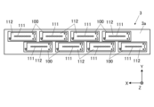
- FIG. 2 is a schematic diagram showing the configuration of the head unit 3, and is a plan view of the head unit 3 viewed from the side facing the conveying surface of the conveying belt 2c.
- the head unit 3 has a plate-like base portion 3a and a plurality of (here, eight) inkjet heads 100 fixed to the base portion 3a in a state of being fitted in through holes provided in the base portion 3a.
- the inkjet head 100 is fixed to the base 3a in a state in which a nozzle opening surface 112 provided with openings of the nozzles 111 is exposed in the -Z direction from the through hole of the base 3a.
- each inkjet head 100 has a row (nozzle row) of nozzles 111 that are one-dimensionally arranged at equal intervals in the X direction.
- the inkjet head 100 may have a plurality of nozzle rows. In this case, the plurality of nozzle rows are arranged with their X-direction positions shifted so that the positions of the nozzles 111 in the X-direction do not overlap.
- the eight inkjet heads 100 in the head unit 3 are arranged in a houndstooth pattern so that the arrangement range of the nozzles 111 in the X direction is continuous.
- the arrangement range in the X direction of the nozzles 111 included in the head unit 3 covers the width in the X direction of the image printable area of the recording medium M transported by the transport belt 2c.
- the head unit 3 is used at a fixed position when recording an image, and ejects ink from the nozzles 111 to each position at a predetermined interval in the transport direction (transport direction interval) as the recording medium M is transported.
- the image is recorded by the single pass method.
- FIG. 3 is a perspective view of the inkjet head 100.
- the inkjet head 100 includes a housing 101 and an exterior member 102 that is fitted to the housing 101 at the lower end of the housing 101. Main components are housed inside the housing 101 and the exterior member 102.
- the exterior member 102 is provided with an inlet 103a to which ink is supplied from the outside, and outlets 103b and 103c from which the ink is discharged to the outside.
- an ink chamber 300 (see FIG. 5) connected to the inlet 103a is provided inside the exterior member 102 .
- the exterior member 102 is provided with a plurality of mounting holes 104 for mounting the inkjet head 100 on the base portion 3 a of the head unit 3 .
- FIG. 4 is an exploded perspective view of the main parts of the inkjet head 100.
- FIG. FIG. 4 shows main constituent members housed inside the exterior member 102 among the constituent members of the inkjet head 100 .
- a nozzle substrate 11, a flow path substrate 12, a pressure chamber substrate 13, a head chip 10 having a wiring substrate 14, and an FPC 20 (flexible printed circuit board) electrically connected to the wiring substrate 14 are shown.
- Circuit is shown.
- each member is depicted such that the nozzle opening surface 112 of the inkjet head 100 faces upward, that is, the members are depicted upside down with respect to FIG.
- the head chip 10 has a structure in which a nozzle substrate 11, a channel substrate 12, a pressure chamber substrate 13, and a wiring substrate 14 are laminated.
- Each of the nozzle substrate 11, the flow path substrate 12, the pressure chamber substrate 13, and the wiring substrate 14 is a plate-shaped member elongated in the X direction and having a substantially quadrangular prism shape.
- the nozzle substrate 11 is a polyimide substrate on which nozzles 111, which are holes penetrating in the thickness direction (Z direction), are arranged in rows along the X direction.
- the ⁇ Z direction side surface of the nozzle substrate 11 forms a nozzle opening surface 112 of the inkjet head 100 .
- the channel substrate 12 is provided with a through channel 121 (first channel) communicating with the nozzle 111 and individual discharge channels 122 branching from the through channel 121 .
- the pressure chamber substrate 13 includes pressure chambers 131 communicating with the through channels 121 , common discharge channels 132 communicating with the individual discharge channels 122 , and vertical discharge channels 133 communicating with the common discharge channels 132 .
- the wiring substrate 14 is provided with an ink supply channel 141 (second channel) communicating with the pressure chamber 131 through the second opening 1412, and a discharge hole 142 communicating with the vertical discharge channel 133. It is
- the flow path substrate 12 and the pressure chamber substrate 13 are rectangular parallelepiped plate members having substantially the same shape as the nozzle substrate 11 when viewed in the Z direction.
- the channel substrate 12 is made of, for example, a silicon substrate.
- the nozzle substrate 11 and the pressure chamber substrate 13 are bonded (fixed) to the -Z direction side surface of the channel substrate 12 and the +Z direction side surface, respectively, via an adhesive.
- the material of the pressure chamber substrate 13 is a ceramic piezoelectric body (a member that deforms according to voltage application). Examples of such piezoelectric materials include PZT (lead zirconate titanate), lithium niobate, barium titanate, lead titanate, and lead metaniobate. PZT is used for the pressure chamber substrate 13 of the present embodiment.
- the wiring substrate 14 is a flat substrate having an area larger than that of the pressure chamber substrate 13, and is adhered to the +Z direction side surface of the pressure chamber substrate 13 via an adhesive.
- the wiring board 14 for example, a board made of glass, ceramics, silicon, plastic, or the like can be used.
- FIG. 5 is a cross-sectional view showing the configuration of the inkjet head 100.
- FIG. FIG. 5 is a diagram showing a cross section perpendicular to the Y direction at the position of line AA in FIG.
- the +Z direction is also referred to as upward
- the ⁇ Z direction is also referred to as downward.
- the ink channel 15 and the nozzles 111 constitute an ink discharge flow path 16 .
- the ink chamber 300 is arranged on the upper side (+Z direction side) of the opening forming surface 10a of the head chip 10 where the first opening 1411 is formed.
- the ink chamber 300 communicates with the ink channel 15 through a first opening 1411 formed in the opening forming surface 10a.
- the ink in the ink chamber 300 is commonly supplied to the plurality of ink channels 15 and ejected from the nozzles 111 .
- An electrode (not shown) is formed on the inner wall surface of the ink channel 15 .
- the wall surface between the ink channels 15 (more specifically, the portion of the wall surface made of the piezoelectric material of the pressure chamber substrate 13 (the partition wall 17)) is displaced according to the potential difference of the drive signal applied to the electrodes of the adjacent ink channels 15. .
- the wall surface repeats shear mode type displacement, the pressure of the ink in the ink channel 15 fluctuates. is discharged from the nozzle 111 . That is, the inkjet head 100 of the present embodiment performs shear mode type ink ejection.
- first individual channels 1221 branch from each of the plurality of through channels 121 (ink channels 15) in the +Y direction.
- a second individual flow path 1222 extending in the +Z direction and penetrating the flow path substrate 12 is connected to the +Y direction end of .
- the individual discharge channel 122 is configured by the first individual channel 1221 and the second individual channel 1222 .
- a joint surface of the pressure chamber substrate 13 with the channel substrate 12 is provided with grooves forming a common discharge channel 132 extending in the X direction in a range overlapping with the plurality of second individual channels 1222 when viewed from the Z direction. ing.
- the common discharge channel 132 is formed by closing the opening of the groove provided in the pressure chamber substrate 13 with the channel substrate 12 in a state in which the channel substrate 12 and the pressure chamber substrate 13 are joined. be. Further, the common discharge channel 132 is connected to the plurality of individual discharge channels 122 when the channel substrate 12 and the pressure chamber substrate 13 are joined together.
- a vertical discharge channel 133 penetrating the pressure chamber substrate 13 in the Z direction is connected to the +X direction end of the common discharge channel 132 .
- the wiring board 14 is provided with a discharge hole 142 penetrating through the wiring board 14 at a position overlapping the vertical discharge channel 133 when viewed in the Z direction. An opening 1421 of the discharge hole 142 communicates with the outlet 103b (or the outlet 103c).
- the individual discharge flow path 122, common discharge flow path 132, vertical discharge flow path 133, and discharge hole 142 constitute an ink discharge flow path.
- a plurality of wirings 143 connected to the electrodes of the ink channels 15 are provided on the bonding surface of the wiring substrate 14 with the pressure chamber substrate 13 . Further, the FPC 20 is connected to the end of the wiring board 14 where the wiring 143 is provided via, for example, ACF (anisotropic conductive film). Drive signals output from a drive circuit (not shown) are supplied to the electrodes of the ink channel 15 via the wiring 21 on the FPC 20 and the wiring 143 .
- ACF anisotropic conductive film
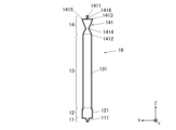
- FIG. 6 shows a cross-sectional view of the ink ejection channel 16 perpendicular to the Y direction.
- the ink in the ink chamber 300 is supplied to the ink supply channel 141 through the first opening 1411, and the ink in the ink supply channel 141 flows through the second opening 1412. is supplied to the pressure chamber 131 via the
- FIG. 7 shows a perspective view of the ink supply channel 141.
- the ink supply channel 141 is located between the first opening 1411 and the second opening 1412 and has a cross-sectional area smaller than the first opening 1411 in the XY plane perpendicular to the Z direction.
- a first diaphragm portion 1413 (diaphragm portion) and a second diaphragm portion 1414 having a smaller cross-sectional area in the XY plane than the second opening portion 1412 are provided.
- the ink supply channel 141 includes an enlarged portion 1415 having a larger cross-sectional area in the XY plane than the first narrowed portion 1413 and the second narrowed portion 1414 between the first narrowed portion 1413 and the second narrowed portion 1414 .
- the shape of the first opening 1411 and the cross-sectional shape of the first narrowed portion 1413 in the XY plane are circular, and the ink supply channel 141 has a tapered shape from the first opening 1411 to the first narrowed portion 1413.
- a channel (tapered portion 1416) is provided. Note that the tapered portion 1416 is not limited to the truncated cone shape, and may have any tapered shape.
- the cross-sectional shape of the enlarged portion 1415 and the cross-sectional shape of the second narrowed portion 1414 in the XY plane are oval (or elliptical), and the ink supply channel 141 is long from the enlarged portion 1415 to the second narrowed portion 1414. It has a truncated cone-shaped (or elliptical truncated cone-shaped) channel. Further, the shape of the second opening 1412 is oval (or elliptical), and the ink supply channel 141 has a long truncated cone shape (or an elliptical truncated cone shape) from the second throttle portion 1414 to the second opening 1412. ). As shown in FIGS.
- the ink supply channel 141 is provided with a two-stage throttle of a first throttle portion 1413 and a second throttle portion 1414, thereby driving at a higher speed and ejecting lower viscosity ink. Even in this case, the flow path resistance can be sufficiently increased without increasing the inertance.
- FIG. 8 shows a perspective view of a connecting portion between the pressure chamber 131 and the through channel 121.
- the shape of the pressure chamber 131 and the through channel 121 is a rectangular parallelepiped.
- the cross-sectional area of the through channel 121 on the XY plane is larger than the cross-sectional area of the pressure chamber 131 on the XY plane.
- the Helmholtz resonance period of the pressure chamber 131 in this embodiment is 3 ⁇ s or more and 3.6 ⁇ s or less.
- FIG. 9 shows a perspective view of the nozzle 111.
- the cross-sectional shape in the XY plane of the connecting portion 1111 that connects to the through-channel 121 is an elliptical (or elliptical) shape, and the cross-sectional shape in the XY plane of the ejection port 1112 that ejects ink.
- the shape is circular.
- FIG. 10 shows an example of characteristics of normalized droplet velocity (normalized velocity) and drive cycle in driving the inkjet head.
- the first narrowed portion 1413 has a diameter of 30 [ ⁇ m].
- a so-called waviness in which the droplet velocity has a long fluctuation cycle, can be seen.
- the vibration mode A the difference in droplet velocity between long-cycle (eg, 15 to 30 [/AL]) driving and short-cycle (eg, 3 to 15 [/AL]) driving becomes large, and ejection becomes unstable.
- AL Acoustic Length
- AL is 1/2 of the acoustic resonance period of the pressure wave in the pressure chamber 131, and is the velocity It is the pulse width at which the change is measured and the velocity of interest is maximized.
- the vibration mode B centered on the compliance, which is the elastic component of the pressure chamber 131 .
- the ink discharge flow path 16 is configured as follows.
- R U is the channel resistance of the ink supply channel 141
- R C is the channel resistance of the pressure chamber 131
- R D be the resistance
- R N be the flow path resistance of the nozzle 111
- the inertance of the ink supply channel 141 is L U
- the inertance of the pressure chamber 131 is L C
- the inertance of the through channel 121 is L D
- the inertance of the nozzle 111 is L N .
- CN be the compliance of the meniscus in the nozzle 111 .
- the flow path resistance R [Pa ⁇ s/m 3 ] is generally represented by the following formula (A1).
- ⁇ Viscosity of fluid [Pa s]
- S(x) Cross-sectional area perpendicular to ink flow [m 2 ]
- ⁇ (x) Equivalent length perpendicular to the channel [m] Therefore, the channel resistance R [Pa ⁇ s/m 3 ] of the cylindrical channel is represented by the following formula (A2).
- L length of channel [m]
- d diameter of the circle corresponding to the cross section [m]
- the channel resistance R [Pa ⁇ s/m 3 ] of the quadrangular prism channel is represented by the following formula (A3).
- the channel resistance R [Pa ⁇ s/m 3 ] of the truncated cone channel is represented by the following formula (A4).
- d 1 Diameter of top surface of truncated cone [m]
- d 2 Diameter of top surface of truncated cone [m]
- the flow path resistance may be calculated by numerical calculation of the fluid using the finite element method or the like.
- the flow path resistance R [Pa ⁇ s/m 3 ] in that case is represented by the following formula (A5).
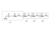
- FIG. 11 shows an example of an equivalent circuit model of the ink ejection channel 16 viewed from the nozzle 111.
- the first combined resistance RM of the ink ejection channel 16 in the example shown in FIG. 11 is represented by the following formula (1).
- Formula (1): R M R U + R C + R D + R N
- FIG. 12 shows the relationship between the first combined resistance RM and the drop rate of the droplet velocity a, which is the minimum droplet velocity, with respect to the droplet velocity at which ejection is stable.
- the viscosity of the ink is 5 mPa ⁇ s or more and 7 mPa ⁇ s or less.
- the ink discharge flow path 16 is configured so as to satisfy the following formula (2).
- R M 4.9 ⁇ 10 13 Pa ⁇ s/m 3
- the reduced droplet landing deviation is 42.233 [ ⁇ m], which corresponds to one pixel at a resolution of 600 [dpi]. Therefore, the maximum deviation of landing of droplets in the ink ejection channel 16 that satisfies the formula (2) is 42.233 [ ⁇ m], and the ink can be stably ejected.
- the ink ejection flow path 16 is configured to satisfy the following formula (3) in order to set the drop rate of the droplet velocity a to -13% or more based on the droplet velocity of 6 m/s.
- Formula (3): R M ⁇ 5.8 ⁇ 10 13 Pa ⁇ s/m 3 RM 5.8 ⁇ 10 13 Pa ⁇ s/m 3 , resolution: 600 [dpi], drive frequency: 30 [kHz], distance between recording medium M and ejection port 1112 of nozzle 111: 1 [mm],
- the conveying speed of the recording medium M is 1.27 [m/s]
- the landing deviation is 0.75 pixels. Therefore, the deviation of landing of droplets in the ink ejection channel 16 that satisfies the formula (3) is 0.75 pixels at maximum, and the ink can be ejected more stably.
- the ink discharge channel 16 is arranged so as to satisfy the following formula (4).
- Configure. Formula (4): R M ⁇ 6.7 ⁇ 10 13 Pa ⁇ s/m 3 RM 6.7 ⁇ 10 13 Pa ⁇ s/m 3 , resolution: 600 [dpi], drive frequency: 30 [kHz], distance between recording medium M and ejection port 1112 of nozzle 111: 1 [mm],
- the conveying speed of the recording medium M is 1.27 [m/s]
- the landing deviation is 0.5 pixels. Therefore, the deviation of landing of droplets in the ink ejection channel 16 that satisfies the formula (4) is 0.5 pixels at maximum, and the ink can be ejected more stably.
- the ink discharge channel 16 is preferably configured so as to satisfy the following formula (5).
- Formula (5): R M ⁇ 2.2 ⁇ 10 14 Pa ⁇ s/m 3 RM 2.2 ⁇ 10 14 Pa ⁇ s/m 3 , resolution: 600 [dpi], drive frequency: 30 [kHz], distance between recording medium M and ejection port 1112 of nozzle 111: 1 [mm],
- the conveying speed of the recording medium M is 1.27 [m/s]
- the drop rate of the droplet speed a is 11%
- the landing deviation of the droplet is -0.5 pixel.
- the ink can be stably ejected.
- FIG. 13 shows an example of an equivalent circuit model of the ink discharge channel 16 viewed from the center of the pressure chamber 131, where C is the compliance of the pressure chamber 131.
- the second combined resistance RT of the ink discharge flow path 16 is represented by the following formula (6).
- Formula (6): R T (R U + R C /2) x (R C /2 + R D + R N )/(R U + R C + R D + R N )
- FIG. 14 shows the relationship between the second combined resistance RT and the pixel deviation caused by the variation in the ink (droplet) landing positions among the pressure chambers 131 in the vibration mode B described above.
- the viscosity of the ink is 5 mPa ⁇ s or more and 7 mPa ⁇ s or less.
- drive frequency: 30 [kHz] distance between print medium M and ejection port 1112 of nozzle 111: 1 [mm]
- transport speed of print medium M 1.27 [m/s].
- the ink discharge flow path 16 is constructed so as to satisfy the following formula (7).
- the ink ejection channel 16 is configured to satisfy the following formula (8).
- Formula (8) R T ⁇ 1.9 ⁇ 10 13 Pa ⁇ s/m 3 As a result, it is possible to suppress pixel deviation due to variations in ink landing positions among the pressure chambers 131 to 0.1 pixel or less.
- FIG. 15 shows the relationship between the ratio of the area of the ejection port 1112 of the nozzle 111 to the cross-sectional area of the flow path in the first narrowed portion 1413 and the pixel deviation caused by the variation in the ink landing positions among the pressure chambers 131 .
- the viscosity of the ink is 5 mPa ⁇ s or more and 7 mPa ⁇ s or less.
- drive frequency 30 [kHz]
- transport speed of print medium M 1.27 [m/s].
- FIG. 15 shows the relationship between the ratio of the area of the ejection port 1112 of the nozzle 111 to the cross-sectional area of the flow path in the first narrowed portion 1413 and the pixel deviation caused by the variation in the ink landing positions among the pressure chambers 131 .
- the viscosity of the ink is 5 mPa ⁇ s or more and 7
- the channel in the first narrowed portion 1413 The ratio of the area of the ejection port 1112 of the nozzle 111 to the cross-sectional area is 0.44 or more. Note that the larger the ratio of the area of the ejection port 1112 of the nozzle 111 to the cross-sectional area of the passage in the first narrowed portion 1413, the smaller the pixel shift. It is desirable to keep it below 70.
- the present invention is not limited to the above embodiments, and various modifications are possible.
- the ink ejection channel 16 is configured to satisfy the above formulas (2) and (7), but the present invention is not limited to this.
- the ink discharge channel 16 may be configured to satisfy the above formula (2) or the above formula (7).
- the shear mode inkjet head 100 has been described as an example, but the present invention is not limited to this.
- the present invention may be applied to a vent mode ink jet head that ejects ink by varying the pressure of the ink in the pressure chamber.
- the pressure chambers of the shear mode inkjet head are difficult to form in terms of production technology so as to suppress an increase in inertance while greatly increasing the flow path resistance. more effective.
- the inkjet head 100 of the present embodiment has a plurality of nozzles 111 for ejecting ink, a plurality of pressure chambers 131 for varying the pressure of ink stored therein, and a plurality of pressure chambers 131 for supplying ink to the plurality of pressure chambers 131 .
- An ink chamber 300 that stores ink, a first channel (through channel 121) that individually communicates the nozzle 111 and the pressure chamber 131, and a second channel that individually communicates the pressure chamber 131 and the ink chamber 300.
- the inkjet head 100 of this embodiment includes a plurality of nozzles 111 for ejecting ink, a plurality of pressure chambers 131 for varying the pressure of the ink stored therein, and a plurality of pressure chambers 131 for storing ink to be supplied.
- a first channel (through channel 121) that individually communicates the ink chamber 300, the nozzle 111, and the pressure chamber 131; flow path 141), which includes a flow path resistance RN of the nozzle 111, a flow path resistance R C of the pressure chamber 131, a flow path resistance R D of the first flow path, and a flow path resistance R D of the second flow path R U satisfies the following formula (2).
- the inkjet head 100 of this embodiment includes a plurality of nozzles 111 for ejecting ink, a plurality of pressure chambers 131 for varying the pressure of the ink stored therein, and a plurality of pressure chambers 131 for storing ink to be supplied.
- a first channel (through channel 121) that individually communicates the ink chamber 300, the nozzle 111, and the pressure chamber 131; flow path 141), which includes a flow path resistance RN of the nozzle 111, a flow path resistance R C of the pressure chamber 131, a flow path resistance R D of the first flow path, and a flow path resistance R D of the second flow path R U satisfies the following formulas (1) and (2).
- Formula (1) R U + R C + R D + R N ⁇ 4.9 ⁇ 10 13 Pa ⁇ s/m 3
- Formula (2) (R U +R C /2) ⁇ (R C /2+R D +R N )/(R U +R C +R D +R N ) ⁇ 1.1 ⁇ 10 13 Pa ⁇ s/m 3 Therefore, even when the ink jet head 100 is driven at a higher speed to eject ink with a lower viscosity, the effects of the vibration modes A and B can be suppressed, and stable ejection can be performed.
- the viscosity of the ink is 5 mPa ⁇ s or more and 7 mPa ⁇ s or less. Therefore, even when the viscosity of the ink is the above value, the influence of the vibration mode A and the vibration mode B can be suppressed, so stable ejection can be performed. Further, even when the viscosity of the ink is other than 5 mPa ⁇ s or more and 7 mPa ⁇ s or less, the ink discharge channel 16 is arranged so as to satisfy either or both of the above formulas (1) and (2). , it is possible to obtain an effect that stable ejection can be performed.
- the present invention is particularly effective when the viscosity of the ink is 5 mPa ⁇ s or more and 7 mPa ⁇ s or less.
- the second channel has a constricted portion (first constricted portion 1413) having a channel cross-sectional area smaller than that of other portions in the second channel, and has a tapered shape.
- a taper 1416 is provided.
- the side with the larger cross-sectional area of the flow path is positioned on the ink chamber 300 side, and the side with the smaller cross-sectional area of the flow path is positioned on the pressure chamber 131 side. Therefore, even when driving at a higher speed and ejecting ink with a lower viscosity, the flow path resistance of the second flow path can be sufficiently increased without increasing the inertance.
- the second flow path has a two-stage throttle including a throttle portion. Therefore, even when driving at a higher speed and ejecting ink with a lower viscosity, the flow path resistance can be sufficiently increased without increasing the inertance.
- the ratio of the area of the ejection openings 1112 of the nozzles 111 to the cross-sectional area of the channel in the constricted portion is 0.44 or more. In this case, it is possible to suppress the pixel deviation due to the variation in the landing position of the ink between the pressure chambers 131 to 0.2 pixel or less, so that the ink can be discharged stably.
- the Helmholtz resonance period of the pressure chamber 131 is 3 ⁇ s or more and 3.6 ⁇ s or less. Therefore, even in the inkjet head 100 in which the Helmholtz resonance period of the pressure chamber 131 is 3 ⁇ s or more and 3.6 ⁇ s or less, stable ejection can be performed.
- the inkjet head 100 of the present embodiment includes a common partition 17 made of a piezoelectric material between the adjacent pressure chambers 131, and shearing deformation of the partition 17 to change the volume of the pressure chamber 131 is a shear mode type inkjet. is the head.
- the present invention is more effective in the shear mode inkjet head because it is difficult from the viewpoint of production technology to shape the pressure chambers of the shear mode inkjet head so as to greatly increase the flow path resistance while suppressing an increase in inertance. is.
- the present invention is not limited to the above embodiments, and various modifications are possible.
- the vertical discharge channel 133 is provided at one end of the common discharge channel 132, and the ink is discharged only from the one end.
- discharge channels may be provided at both ends of the common discharge channel 132 to discharge ink from both ends of the common discharge channel 132 .
- the common discharge channel 132 is configured by a groove provided on the surface of the pressure chamber substrate 13 on the channel substrate 12 side has been described, but it is not limited to this.
- the common discharge channel 132 may be formed across the channel substrate 12 and the pressure chamber substrate 13 .
- the pressure chamber substrate 13 and the nozzle substrate 11 may be directly bonded without providing the flow path substrate 12 .
- the pressure chamber substrate 13 is provided with individual discharge channels and a common discharge channel.
- grooves provided on the surface of the pressure chamber substrate 13 on the nozzle substrate 11 side can form a common discharge channel.
- the recording medium M is transported by the transport unit 2 having the transport belt 2c. It may be one that holds and conveys the recording medium M on the outer peripheral surface.
- the single-pass type inkjet recording apparatus 1 is described as an example, but the present invention may be applied to an inkjet recording apparatus that records an image while scanning the inkjet head 100 .
- This invention can be used for inkjet heads and inkjet recording devices.
- Reference Signs List 1 inkjet recording device 2 conveying section 3 head unit 10 head chip 11 nozzle substrate 111 nozzle 1111 connecting portion 1112 discharge port 112 nozzle opening surface 12 channel substrate 121 through channel (first channel) 122 individual discharge channel 1221 first individual channel 1222 second individual channel 13 pressure chamber substrate 131 pressure chamber 132 common discharge channel 133 vertical discharge channel 14 wiring board 141 ink supply channel (second channel) 1411 First opening 1412 Second opening 1413 First aperture (diaphragm) 1414 Second narrowed portion 1415 Enlarged portion 1416 Tapered portion 15 Ink channel 16 Ink discharge channel 17 Partition wall 100 Inkjet head 101 Housing 102 Exterior member 103a Inlets 103b, 103c Outlet M Recording medium
Landscapes
- Particle Formation And Scattering Control In Inkjet Printers (AREA)
Abstract
La présente invention permet une évacuation stable même lorsqu'une tête à jet d'encre (100) est entraînée à une vitesse plus élevée et de l'encre présentant une viscosité inférieure est évacuée. La tête à jet d'encre (100) comprend : une pluralité de buses (111) qui injectent de l'encre ; une pluralité de chambres de pression (131) destinées à modifier la pression d'encre stockée en son sein ; une chambre d'encre (300) qui stocke de l'encre devant être fournie à la pluralité de chambres de pression (131) ; un premier trajet d'écoulement (trajet d'écoulement traversant (121)) destiné à faire communiquer individuellement la buse (111) avec la chambre de pression (131) ; et un second trajet d'écoulement (trajet d'écoulement d'alimentation en encre (141)) destiné à faire communiquer individuellement la chambre de pression (131) avec la chambre d'encre (300). La résistance de trajet d'écoulement RN de la buse (111), la résistance de trajet d'écoulement RC de la chambre de pression (131), la résistance de trajet d'écoulement RD du premier trajet d'écoulement et la résistance de trajet d'écoulement RU du second trajet d'écoulement satisfont la formule suivante (1). Formule (1) : RU + RC + RD + RN ≥ 4,9 × 10¹³ Pa•s/m3
Priority Applications (1)
| Application Number | Priority Date | Filing Date | Title |
|---|---|---|---|
| PCT/JP2022/006184 WO2023157127A1 (fr) | 2022-02-16 | 2022-02-16 | Tête à jet d'encre et dispositif d'impression à jet d'encre |
Applications Claiming Priority (1)
| Application Number | Priority Date | Filing Date | Title |
|---|---|---|---|
| PCT/JP2022/006184 WO2023157127A1 (fr) | 2022-02-16 | 2022-02-16 | Tête à jet d'encre et dispositif d'impression à jet d'encre |
Publications (1)
| Publication Number | Publication Date |
|---|---|
| WO2023157127A1 true WO2023157127A1 (fr) | 2023-08-24 |
Family
ID=87577840
Family Applications (1)
| Application Number | Title | Priority Date | Filing Date |
|---|---|---|---|
| PCT/JP2022/006184 WO2023157127A1 (fr) | 2022-02-16 | 2022-02-16 | Tête à jet d'encre et dispositif d'impression à jet d'encre |
Country Status (1)
| Country | Link |
|---|---|
| WO (1) | WO2023157127A1 (fr) |
Citations (7)
| Publication number | Priority date | Publication date | Assignee | Title |
|---|---|---|---|---|
| JPH0640030A (ja) * | 1992-05-27 | 1994-02-15 | Ngk Insulators Ltd | インクジェットプリントヘッド |
| JP2009166242A (ja) * | 2007-01-12 | 2009-07-30 | Seiko Epson Corp | 液体噴射ヘッド及びこれを有する液体噴射装置 |
| JP2009226943A (ja) * | 2008-02-26 | 2009-10-08 | Seiko Epson Corp | 液体噴射ヘッド及び液体噴射装置 |
| US20100060687A1 (en) * | 2008-09-09 | 2010-03-11 | Samsung Electronics Co., Ltd. | Inkjet printhead |
| WO2014006877A1 (fr) * | 2012-07-05 | 2014-01-09 | パナソニック株式会社 | Appareil à jet d'encre et procédé pour fabriquer un dispositif el organique |
| WO2018008397A1 (fr) * | 2016-07-04 | 2018-01-11 | コニカミノルタ株式会社 | Appareil d'enregistrement à jet d'encre |
| JP2019127030A (ja) * | 2018-01-19 | 2019-08-01 | 株式会社リコー | 液体吐出ヘッドおよび液体を吐出する装置 |
-
2022
- 2022-02-16 WO PCT/JP2022/006184 patent/WO2023157127A1/fr unknown
Patent Citations (7)
| Publication number | Priority date | Publication date | Assignee | Title |
|---|---|---|---|---|
| JPH0640030A (ja) * | 1992-05-27 | 1994-02-15 | Ngk Insulators Ltd | インクジェットプリントヘッド |
| JP2009166242A (ja) * | 2007-01-12 | 2009-07-30 | Seiko Epson Corp | 液体噴射ヘッド及びこれを有する液体噴射装置 |
| JP2009226943A (ja) * | 2008-02-26 | 2009-10-08 | Seiko Epson Corp | 液体噴射ヘッド及び液体噴射装置 |
| US20100060687A1 (en) * | 2008-09-09 | 2010-03-11 | Samsung Electronics Co., Ltd. | Inkjet printhead |
| WO2014006877A1 (fr) * | 2012-07-05 | 2014-01-09 | パナソニック株式会社 | Appareil à jet d'encre et procédé pour fabriquer un dispositif el organique |
| WO2018008397A1 (fr) * | 2016-07-04 | 2018-01-11 | コニカミノルタ株式会社 | Appareil d'enregistrement à jet d'encre |
| JP2019127030A (ja) * | 2018-01-19 | 2019-08-01 | 株式会社リコー | 液体吐出ヘッドおよび液体を吐出する装置 |
Similar Documents
| Publication | Publication Date | Title |
|---|---|---|
| US10350887B2 (en) | Liquid injection apparatus, driving method of liquid injection apparatus and liquid supply apparatus | |
| JP5754188B2 (ja) | 液体吐出ヘッド及び画像形成装置 | |
| US20090225138A1 (en) | Liquid ejection head, liquid ejection apparatus | |
| US20170113457A1 (en) | Inkjet head and inkjet printer | |
| JP2004001366A (ja) | 液体噴射ヘッド及び液体噴射装置 | |
| JP2011131571A (ja) | 液体吐出ヘッド及び画像形成装置 | |
| JP2940544B1 (ja) | インクジェット記録ヘッド | |
| EP2078610A2 (fr) | Puce de tête à jet d'encre, procédé de commande pour puce de tête à jet d'encre, tête à jet d'encre, et appareil d'enregistrement à jet d'encre | |
| JP2004255838A (ja) | インクジェットヘッド | |
| WO2023157127A1 (fr) | Tête à jet d'encre et dispositif d'impression à jet d'encre | |
| US11724500B2 (en) | Liquid ejection head | |
| JP3888454B2 (ja) | 液体噴射ヘッド及び液体噴射装置 | |
| JP6989023B2 (ja) | インクジェットヘッド及びインクジェット記録装置 | |
| JP2012218251A (ja) | 液体噴射ヘッド及び液体噴射装置 | |
| JP2015134459A (ja) | 流路ユニット、液体噴射ヘッド、液体噴射装置 | |
| JP2004017600A (ja) | 液体噴射ヘッド及び液体噴射装置 | |
| WO2023175924A1 (fr) | Tête à jet d'encre et dispositif d'enregistrement à jet d'encre | |
| US11691417B2 (en) | Inkjet head | |
| JP2012250492A (ja) | 液体噴射ヘッドユニット及び液体噴射装置 | |
| US11465416B2 (en) | Inkjet head and inkjet recording device | |
| US20240140091A1 (en) | Liquid ejecting head and liquid ejecting apparatus | |
| US20220032622A1 (en) | Liquid discharge head and liquid discharge apparatus | |
| JP2022154957A (ja) | 液体吐出ヘッド | |
| JP6152915B2 (ja) | 液体噴射ヘッド及び液体噴射装置 | |
| JP2023032310A (ja) | 液体吐出ヘッド及び液体吐出ヘッドの製造方法 |
Legal Events
| Date | Code | Title | Description |
|---|---|---|---|
| 121 | Ep: the epo has been informed by wipo that ep was designated in this application |
Ref document number: 22927030 Country of ref document: EP Kind code of ref document: A1 |