WO2023157113A1 - 処理装置、分布型音響センシングシステム、分布型音響センシング方法及びプログラムが格納された非一時的なコンピュータ可読媒体 - Google Patents
処理装置、分布型音響センシングシステム、分布型音響センシング方法及びプログラムが格納された非一時的なコンピュータ可読媒体 Download PDFInfo
- Publication number
- WO2023157113A1 WO2023157113A1 PCT/JP2022/006120 JP2022006120W WO2023157113A1 WO 2023157113 A1 WO2023157113 A1 WO 2023157113A1 JP 2022006120 W JP2022006120 W JP 2022006120W WO 2023157113 A1 WO2023157113 A1 WO 2023157113A1
- Authority
- WO
- WIPO (PCT)
- Prior art keywords
- gauge length
- signal
- section
- short
- long
- Prior art date
- Legal status (The legal status is an assumption and is not a legal conclusion. Google has not performed a legal analysis and makes no representation as to the accuracy of the status listed.)
- Ceased
Links
Images







Classifications
-
- G—PHYSICS
- G01—MEASURING; TESTING
- G01D—MEASURING NOT SPECIALLY ADAPTED FOR A SPECIFIC VARIABLE; ARRANGEMENTS FOR MEASURING TWO OR MORE VARIABLES NOT COVERED IN A SINGLE OTHER SUBCLASS; TARIFF METERING APPARATUS; MEASURING OR TESTING NOT OTHERWISE PROVIDED FOR
- G01D5/00—Mechanical means for transferring the output of a sensing member; Means for converting the output of a sensing member to another variable where the form or nature of the sensing member does not constrain the means for converting; Transducers not specially adapted for a specific variable
- G01D5/26—Mechanical means for transferring the output of a sensing member; Means for converting the output of a sensing member to another variable where the form or nature of the sensing member does not constrain the means for converting; Transducers not specially adapted for a specific variable characterised by optical transfer means, i.e. using infrared, visible, or ultraviolet light
- G01D5/32—Mechanical means for transferring the output of a sensing member; Means for converting the output of a sensing member to another variable where the form or nature of the sensing member does not constrain the means for converting; Transducers not specially adapted for a specific variable characterised by optical transfer means, i.e. using infrared, visible, or ultraviolet light with attenuation or whole or partial obturation of beams of light
- G01D5/34—Mechanical means for transferring the output of a sensing member; Means for converting the output of a sensing member to another variable where the form or nature of the sensing member does not constrain the means for converting; Transducers not specially adapted for a specific variable characterised by optical transfer means, i.e. using infrared, visible, or ultraviolet light with attenuation or whole or partial obturation of beams of light the beams of light being detected by photocells
- G01D5/353—Mechanical means for transferring the output of a sensing member; Means for converting the output of a sensing member to another variable where the form or nature of the sensing member does not constrain the means for converting; Transducers not specially adapted for a specific variable characterised by optical transfer means, i.e. using infrared, visible, or ultraviolet light with attenuation or whole or partial obturation of beams of light the beams of light being detected by photocells influencing the transmission properties of an optical fibre
- G01D5/35338—Mechanical means for transferring the output of a sensing member; Means for converting the output of a sensing member to another variable where the form or nature of the sensing member does not constrain the means for converting; Transducers not specially adapted for a specific variable characterised by optical transfer means, i.e. using infrared, visible, or ultraviolet light with attenuation or whole or partial obturation of beams of light the beams of light being detected by photocells influencing the transmission properties of an optical fibre using other arrangements than interferometer arrangements
- G01D5/35354—Sensor working in reflection
- G01D5/35358—Sensor working in reflection using backscattering to detect the measured quantity
- G01D5/35361—Sensor working in reflection using backscattering to detect the measured quantity using elastic backscattering to detect the measured quantity, e.g. using Rayleigh backscattering
-
- G—PHYSICS
- G01—MEASURING; TESTING
- G01D—MEASURING NOT SPECIALLY ADAPTED FOR A SPECIFIC VARIABLE; ARRANGEMENTS FOR MEASURING TWO OR MORE VARIABLES NOT COVERED IN A SINGLE OTHER SUBCLASS; TARIFF METERING APPARATUS; MEASURING OR TESTING NOT OTHERWISE PROVIDED FOR
- G01D5/00—Mechanical means for transferring the output of a sensing member; Means for converting the output of a sensing member to another variable where the form or nature of the sensing member does not constrain the means for converting; Transducers not specially adapted for a specific variable
- G01D5/26—Mechanical means for transferring the output of a sensing member; Means for converting the output of a sensing member to another variable where the form or nature of the sensing member does not constrain the means for converting; Transducers not specially adapted for a specific variable characterised by optical transfer means, i.e. using infrared, visible, or ultraviolet light
- G01D5/32—Mechanical means for transferring the output of a sensing member; Means for converting the output of a sensing member to another variable where the form or nature of the sensing member does not constrain the means for converting; Transducers not specially adapted for a specific variable characterised by optical transfer means, i.e. using infrared, visible, or ultraviolet light with attenuation or whole or partial obturation of beams of light
- G01D5/34—Mechanical means for transferring the output of a sensing member; Means for converting the output of a sensing member to another variable where the form or nature of the sensing member does not constrain the means for converting; Transducers not specially adapted for a specific variable characterised by optical transfer means, i.e. using infrared, visible, or ultraviolet light with attenuation or whole or partial obturation of beams of light the beams of light being detected by photocells
- G01D5/353—Mechanical means for transferring the output of a sensing member; Means for converting the output of a sensing member to another variable where the form or nature of the sensing member does not constrain the means for converting; Transducers not specially adapted for a specific variable characterised by optical transfer means, i.e. using infrared, visible, or ultraviolet light with attenuation or whole or partial obturation of beams of light the beams of light being detected by photocells influencing the transmission properties of an optical fibre
- G01D5/35338—Mechanical means for transferring the output of a sensing member; Means for converting the output of a sensing member to another variable where the form or nature of the sensing member does not constrain the means for converting; Transducers not specially adapted for a specific variable characterised by optical transfer means, i.e. using infrared, visible, or ultraviolet light with attenuation or whole or partial obturation of beams of light the beams of light being detected by photocells influencing the transmission properties of an optical fibre using other arrangements than interferometer arrangements
- G01D5/35354—Sensor working in reflection
- G01D5/35358—Sensor working in reflection using backscattering to detect the measured quantity
-
- G—PHYSICS
- G01—MEASURING; TESTING
- G01D—MEASURING NOT SPECIALLY ADAPTED FOR A SPECIFIC VARIABLE; ARRANGEMENTS FOR MEASURING TWO OR MORE VARIABLES NOT COVERED IN A SINGLE OTHER SUBCLASS; TARIFF METERING APPARATUS; MEASURING OR TESTING NOT OTHERWISE PROVIDED FOR
- G01D5/00—Mechanical means for transferring the output of a sensing member; Means for converting the output of a sensing member to another variable where the form or nature of the sensing member does not constrain the means for converting; Transducers not specially adapted for a specific variable
- G01D5/26—Mechanical means for transferring the output of a sensing member; Means for converting the output of a sensing member to another variable where the form or nature of the sensing member does not constrain the means for converting; Transducers not specially adapted for a specific variable characterised by optical transfer means, i.e. using infrared, visible, or ultraviolet light
- G01D5/32—Mechanical means for transferring the output of a sensing member; Means for converting the output of a sensing member to another variable where the form or nature of the sensing member does not constrain the means for converting; Transducers not specially adapted for a specific variable characterised by optical transfer means, i.e. using infrared, visible, or ultraviolet light with attenuation or whole or partial obturation of beams of light
- G01D5/34—Mechanical means for transferring the output of a sensing member; Means for converting the output of a sensing member to another variable where the form or nature of the sensing member does not constrain the means for converting; Transducers not specially adapted for a specific variable characterised by optical transfer means, i.e. using infrared, visible, or ultraviolet light with attenuation or whole or partial obturation of beams of light the beams of light being detected by photocells
- G01D5/353—Mechanical means for transferring the output of a sensing member; Means for converting the output of a sensing member to another variable where the form or nature of the sensing member does not constrain the means for converting; Transducers not specially adapted for a specific variable characterised by optical transfer means, i.e. using infrared, visible, or ultraviolet light with attenuation or whole or partial obturation of beams of light the beams of light being detected by photocells influencing the transmission properties of an optical fibre
- G01D5/35338—Mechanical means for transferring the output of a sensing member; Means for converting the output of a sensing member to another variable where the form or nature of the sensing member does not constrain the means for converting; Transducers not specially adapted for a specific variable characterised by optical transfer means, i.e. using infrared, visible, or ultraviolet light with attenuation or whole or partial obturation of beams of light the beams of light being detected by photocells influencing the transmission properties of an optical fibre using other arrangements than interferometer arrangements
- G01D5/35341—Sensor working in transmission
- G01D5/35348—Sensor working in transmission using stimulated emission to detect the measured quantity
-
- G—PHYSICS
- G01—MEASURING; TESTING
- G01H—MEASUREMENT OF MECHANICAL VIBRATIONS OR ULTRASONIC, SONIC OR INFRASONIC WAVES
- G01H9/00—Measuring mechanical vibrations or ultrasonic, sonic or infrasonic waves by using radiation-sensitive means, e.g. optical means
- G01H9/004—Measuring mechanical vibrations or ultrasonic, sonic or infrasonic waves by using radiation-sensitive means, e.g. optical means using fibre optic sensors
-
- G—PHYSICS
- G01—MEASURING; TESTING
- G01N—INVESTIGATING OR ANALYSING MATERIALS BY DETERMINING THEIR CHEMICAL OR PHYSICAL PROPERTIES
- G01N29/00—Investigating or analysing materials by the use of ultrasonic, sonic or infrasonic waves; Visualisation of the interior of objects by transmitting ultrasonic or sonic waves through the object
- G01N29/22—Details, e.g. general constructional or apparatus details
- G01N29/24—Probes
- G01N29/2418—Probes using optoacoustic interaction with the material, e.g. laser radiation, photoacoustics
Definitions
- the present invention relates to a non-transitory computer-readable medium storing a processing device, a distributed acoustic sensing system, a distributed acoustic sensing method, and a program.
- DAS Distributed acoustic sensing
- a DAS system generally consists of an optical fiber that senses sound and vibrations and a detection unit called an interrogator.
- An interrogator means "a person who inquires” and illuminates an optical fiber with probe light, receives reflected light or transmitted light from the optical fiber, and detects the state of sound waves and vibrations acting on the optical fiber (Patent Documents 1 to 3 ).
- the sensing in the DAS system has the problem that it is difficult to specify the detailed position of the detected phenomenon (hereinafter referred to as an event).
- an event a section with a predetermined gauge length is set in the optical fiber included in the optical cable laid in the target area, and after measuring the state of sound and vibration generated in the section as a signal, near any section Detect if an event has occurred.
- the intensity of the signal obtained from the return light from the section with a long gauge length is high, and a signal with a high SN (Signal to Noise) ratio is obtained. Therefore, although the occurrence of an event can be easily detected, since the gauge length is long, it is not possible to specify where the event occurs within a long interval.
- the signal obtained from the return light from the short gauge length section has a low intensity and a low SN ratio. Therefore, it is difficult to determine whether the signal fluctuation is due to the occurrence of an event or due to noise or the like, and the accuracy of event detection is deteriorated. Therefore, even if the gauge length is shortened in order to improve the spatial resolution of event detection, it is difficult to suitably detect the event.
- the present invention has been made in view of the above circumstances, and it is an object of the present invention to detect the occurrence of an event with high spatial resolution in a distributed acoustic sensing system.
- a processing apparatus includes a plurality of signal groups obtained based on return light from a plurality of long gauge length sections set in an optical fiber used for distributed acoustic sensing, and a plurality of short gauge lengths.
- a signal acquisition unit for acquiring a plurality of signal groups acquired based on returned light from the section; and selecting a long gauge length section based on a first characteristic quantity of each of the plurality of signal groups of the long gauge length section.
- a signal selection unit for selecting a plurality of short gauge length sections corresponding to the selected long gauge length section; and a second feature amount of each of the selected plurality of short gauge length sections.
- an interval estimator that determines one short gauge length interval as an interval in which an event has occurred.
- a distributed acoustic sensing system which is an aspect of the present invention, comprises an optical fiber used for sensing, a detector that outputs a light pulse to the optical fiber and monitors the returned light, and the returned light from the detector.
- a processing device that receives the monitor results of the optical fiber, the processing device includes a plurality of signal groups acquired based on the return light from a plurality of long gauge length sections set in the optical fiber, and a plurality of short gauge lengths a signal acquisition unit for acquiring a plurality of signal groups acquired based on returned light from the section; and selecting a long gauge length section based on a first characteristic quantity of each of the plurality of signal groups of the long gauge length section.
- a signal selection unit for selecting a plurality of short gauge length sections corresponding to the selected long gauge length section; and a second feature amount of each of the selected plurality of short gauge length sections.
- an interval estimator that determines one short gauge length interval as an interval in which an event has occurred.
- a distributed acoustic sensing method includes a plurality of signal groups acquired based on return light from a plurality of long gauge length sections set in an optical fiber used for distributed acoustic sensing, and a plurality of A plurality of signal groups obtained based on the return light from the short gauge length section are acquired, and a long gauge length section is selected based on the first feature amount of each of the plurality of signal groups of the long gauge length section. , selecting a plurality of short gauge length sections corresponding to the selected long gauge length section, and selecting one short gauge length section based on the second feature quantity of each of the selected plurality of short gauge length section signals A long section is determined as a section in which an event occurs.
- a non-transitory computer-readable medium storing a program which is one aspect of the present invention, is a plurality of non-transitory computer-readable media obtained based on return light from a plurality of long gauge length sections set in an optical fiber used for distributed acoustic sensing. and a plurality of signal groups acquired based on return light from a plurality of short gauge length sections, and a first feature amount of each of the plurality of signal groups of the long gauge length sections. a process of selecting a long gauge length section based on the selected long gauge length section and selecting a plurality of short gauge length sections corresponding to the selected long gauge length section; and determining one short gauge length section as the section in which the event occurred based on the feature amount of .
- the occurrence of an event can be detected with high spatial resolution in a distributed acoustic sensing system.
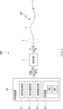
- FIG. 1 is a diagram schematically showing the configuration of a distributed acoustic sensing system according to a first embodiment
- FIG. 1 is a diagram schematically showing the configuration of a processing apparatus according to Embodiment 1
- FIG. 3 is a diagram showing in more detail the configuration of the processing apparatus according to the first embodiment
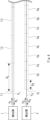
- FIG. FIG. 4 is a diagram schematically showing gauges set on an optical fiber
- FIG. 4 is a diagram showing an example of the relationship between gauge length and signal
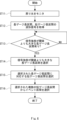
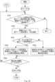
- 4 is a flowchart of event section determination operation of the distributed acoustic sensing system according to the first embodiment
- FIG. 10 is a diagram schematically showing the configuration of a distributed acoustic sensing system according to a second embodiment
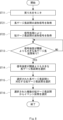
- FIG. 10 is a flowchart of an event section determination operation of the distributed acoustic sensing system according to the second embodiment
- FIG. 12 is a diagram schematically showing the configuration of a distributed acoustic sensing system according to a third embodiment
- FIG. 11 is a flowchart of an event section determination operation of the distributed acoustic sensing system according to the third embodiment
- FIG. FIG. 12 is a diagram schematically showing the configuration of a distributed acoustic sensing system according to a fourth embodiment
- FIG. FIG. 13 is a flow chart of an event section information update operation of the distributed acoustic sensing system according to the fourth embodiment
- FIG. 13 is a flow chart of an event section information update operation of the distributed acoustic sensing system according to the fourth embodiment;
- FIG. FIG. 10 is a flowchart for determining event similarity based on the similarity of short gauge length sections corresponding to two adjacent long gauge length sections;
- FIG. FIG. 11 shows an example with two adjacent long gauge length sections having a shared short gauge length section;
- FIG. 10 illustrates an example in which two adjacent long gauge length sections do not have a shared short gauge length section;
- FIG. 1 schematically shows the configuration of a DAS system 100 according to the first embodiment.
- DAS system 100 comprises detectors 1 and 2, processor 10 and optical fibers FL and FS .
- the processing device 10 is arranged to control the detector 1 by means of a control signal COM L and to control the detector 2 by means of a control signal COM S. Further, the processing device 10 receives the detection signal DET L indicating the detection result from the detection unit 1, receives the detection signal DET S indicating the detection result from the detection unit 2, and performs signal processing required for acoustic sensing. be done.
- optical fibers F L and F S are laid on the same or close paths in the area to be sensed by the acoustic wave AW, and are, for example, fibers included in an optical cable C such as a submarine cable.
- the detector 1 is connected to an optical fiber FL , outputs a light pulse PL to the optical fiber FL , and is configured as a so-called interrogator that detects return light RL that is backscattered light in the optical fiber FL. .
- the detection unit 1 outputs a detection signal DET L , which is the detection result of the returned light RL, to the processing device 10 .
- the detector 2 is connected to an optical fiber FS , outputs a light pulse PS to the optical fiber FS , and is configured as a so-called interrogator that detects a return light RS that is backscattered light in the optical fiber FS . .
- the detector 2 outputs a detection signal DET S , which is the detection result of the returned light RS , to the processing device 10 .
- FIG. 2 schematically shows the configuration of the processing apparatus 10.
- FIG. 3 shows the configuration of the processing apparatus according to the first embodiment in more detail.
- the processing device 10 has a signal acquisition unit 11 , a signal selection unit 12 , an interval estimation unit 13 and a storage unit 14 .
- the signal acquisition unit 11 receives the detection signals DET L and DET S output from the detection units 1 and 2, performs signal processing for conversion into a data format used for signal processing in the signal selection unit 12, and after processing, to the signal selection unit 12 .
- the signal selection unit 12 refers to the received signal group for the long gauge length section, selects the long gauge length section estimated to be closest to the sound source, and selects based on the gauge correspondence information TAB described later.
- the section estimating unit 13 refers to the signal group of the selected short gauge length sections, and determines the short gauge length section estimated to be closest to the sound source as the event section.
- the storage unit 14 stores gauge correspondence information TAB that specifies which short gauge length section corresponds to each long gauge length section, that is, a plurality of short gauge length sections included in one long gauge length section. is stored. Note that the storage unit 14 can also store other information, and the signal acquisition unit 11, the signal selection unit 12, and the interval estimation unit 13 appropriately read necessary information from the storage unit 14, and retrieve the necessary information. It is possible to write to the storage unit 14 .
- FIG. 4 schematically shows gauges set on the optical fibers FL and FS .
- the optical fiber F L has a gauge length G L (hereinafter also referred to as a long gauge length) with a long gauge length section L 1 to L M (M is 2 or more) in a direction away from the detection unit 1. integer) is set.
- a short gauge length section S 1 to S N (N is an integer of 2 or more) of a gauge length G S (hereinafter also referred to as a short gauge length) is set in the optical fiber F S in a direction away from the detection unit 2. It is
- the long gauge length GL and the short gauge length GS can be arbitrary values.
- the long gauge length G L can be several tens of meters
- the short gauge length G S can be several tens of centimeters to several meters.
- Two adjacent long gauge length sections may be associated with short gauge length sections so as not to overlap, or may be associated with short gauge length sections so as to overlap.
- the long gauge length section L 1 has short gauge length sections S 1 to S 3
- the long gauge length section L 2 has short gauge length sections S 4 to S 6
- the long gauge length section L 3 may correspond to the short gauge length sections S 7 to S 9 .
- the short gauge length section S3 located at the boundary between the long gauge length section L1 and the long gauge length section L2 may be shared, and the long gauge length section L2 and the long gauge length section S3 may be shared. It may share a short gauge length section S 6 located at the boundary with section L 3 .
- the long gauge length section L2 includes a short gauge length section S3 shared with the long gauge length section L1 , short gauge length sections S4 and S5 , and a short gauge length shared with the long gauge length section L3.
- Section S6 will correspond. Note that the number of short gauge length sections shared by two adjacent long gauge length sections is not limited to one, and may be any number.
- the detection unit 1 receives return light from each of the long gauge length sections L 1 to L M and outputs detection results
- the detection unit 2 receives return light from each of the short gauge length sections S 1 to S N . It can receive light and output detection results.
- the processing device 10 can then appropriately analyze signals obtained from these detection results.
- the DAS system 100 uses a combination of a signal group obtained from return light from a plurality of long gauge length sections and a signal group obtained from return light from a plurality of short gauge length sections. , to specify the detailed position of the sound source.
- FIG. 5 shows an example of the relationship between gauge length and signal.
- the long gauge length section L and the corresponding short gauge length sections S_1 to S_3 are shown.
- a signal with high intensity and high SN (Signal to Noise) ratio is generally obtained from the return light from the long gauge length section. Therefore, when the sound wave AW reaches the optical fiber FL , the difference in signal strength between adjacent long-gauge length sections becomes relatively large, so the long-gauge length section close to the sound source can be easily identified.
- a signal with a low intensity and a low SN ratio is generally obtained from the return light from the short gauge long section. Therefore, even if the signal intensity of the return light from the short gauge length section is monitored, it is difficult to distinguish between the arrival of the sound wave and the fluctuation of the signal intensity due to a cause other than the sound wave because the signal intensity fluctuates so little.
- the DAS system 100 using the properties due to the difference in gauge length, when a sound wave reaches the optical fiber, first identify the long gauge length section closest to the sound source, and correspond to the identified long gauge length section. That is, by analyzing signals obtained from short gauge length sections provided at similar positions, the short gauge length section closest to the sound source is determined as the event section. Thereby, the DAS system 100 can determine the position (event position) closest to the sound source with high accuracy.
- FIG. 6 shows a flowchart of the event section determination operation in the DAS system 100. As shown in FIG.
- Step ST11 The detector 1 outputs a light pulse PL to the optical fiber FL and monitors the return light RL .
- a detection signal DET L obtained by photoelectrically converting the return light RL is output to the processing device 10 .
- the detector 2 outputs an optical pulse PS to the optical fiber FS and monitors the return light RS . Then, the return light RS is photoelectrically converted and output to the detection signal DETS processing device 10 .
- Step ST12 The signal acquisition unit 11 acquires a signal group in the long gauge length section based on the detection signal DET L , and outputs the acquired signal group to the signal selection unit 12 .
- the signal acquisition unit 11 also acquires a signal group in the short gauge length section based on the detection signal DET L , and outputs the acquired signal group to the signal selection unit 12 .
- Step ST13 The signal selection unit 12 monitors the signal group acquired for each long gauge length section, and determines whether or not there is a long gauge length section in which the first feature amount is greater than the threshold.
- the signal intensity of each long gauge length section is used as the first feature amount of each long gauge length section will be described.
- the signal selection unit 12 monitors a group of signals acquired for each long gauge length section, and determines whether or not there is a long gauge length section in which variation in signal intensity is greater than a threshold.
- Step ST14 When there is a long gauge length section in which the fluctuation of the first feature amount is greater than the threshold, the signal selection unit 12 selects the long gauge length section as an event-generated long gauge length section such as arrival of a sound wave.
- Step ST15 The signal selection unit 12 selects a plurality of short gauge length sections corresponding to the selected long gauge length section.
- a plurality of short gauge length sections corresponding to each of the long gauge length sections are determined in advance, and gauge correspondence information TAB corresponding to the short gauge length sections may be stored in advance in the storage unit 14 as, for example, a data table. good.
- the signal selection unit 12 can refer to the gauge correspondence information TAB as necessary to select a plurality of short gauge length sections corresponding to the selected long gauge length section.
- Step ST16 The interval estimating unit 13 selects a short gauge length interval (hereinafter referred to as event interval ).
- event interval a short gauge length interval
- the processing device 10 acquires the maximum intensity value from each of the waveforms of two or more short gauge length sections, and selects the short gauge length section with the largest maximum value as the event section.
- the signal to be used may be a time waveform signal, or a signal obtained by subjecting the time waveform signal to predetermined processing.
- the degree of similarity may be calculated using a signal to which a low-pass filter has been applied or a signal to which noise suppression processing has been performed for the time waveform signal.
- a so-called spectrogram which is a signal in the time and frequency domain obtained by converting a time waveform signal by Fourier transform or CQT (Constant Q Conversion), may be used.
- the converted signal not only the converted signal itself, but also the binarized signal obtained by subjecting the intensity of the converted waveform signal to discrimination processing using a predetermined threshold value, and the edge signal for emphasizing a point where the intensity changes steeply.
- a signal obtained by subjecting the converted signal to predetermined signal processing such as a signal to which an enhancement filter is applied, may be used.
- a so-called spectrogram may also be used.
- An index indicating the difference between the waveform signal acquired for the selected long gauge length section and the waveform signal acquired for each short gauge length section may be used to calculate the degree of similarity.
- the feature quantity is a multi-dimensional quantity such as a distribution of data points or a vector quantity
- various indexes such as cross-correlation, correlation coefficient, Mahalabinos distance, cosine distance, and Pearson's product-moment correlation coefficient are used as indicators of differences. indicators can be used.
- an index such as the difference between two values or the absolute value of the difference can be used.
- the principal component obtained by performing principal component analysis on the time waveform signal or the signal in the time and frequency domain, or the Mel-frequency cepstrum coefficient of the signal in the time and frequency domain may be used.
- the event section can be determined in detail. position can be narrowed down. That is, the event period can be determined with high spatial resolution.
- the SN ratio of the signal obtained by the occurrence of the event is low, and it is generally difficult to determine whether the signal fluctuation is due to the event or the influence of noise etc. .
- the general position where the event occurred is specified by using the long gauge length section in which a signal with a high SN ratio is obtained. As a result, it can be determined that the intensity fluctuation appearing in the signal of the short gauge length section corresponding to the specified long gauge length section is due to the event, so that the short gauge length section in which the event occurred can be determined with high accuracy. It becomes possible.
- Embodiment 2 In the first embodiment, an example in which one of the two optical fibers is set as the long gauge length section and the other is set as the short gauge length section has been described. Other configurations are possible as long as the constellation of signals is obtained. Another configuration of the DAS system capable of obtaining a group of signals in the long gauge length section and a group of signals in the short gauge length section will be described below.
- FIG. 7 schematically shows the configuration of the DAS system 200 according to the second embodiment.
- the DAS system 200 has a processor 2, a detector 1 and an optical fiber F.
- the detector 1 outputs a light pulse P to the optical fiber F, and monitors the return light R from the gauge section having a predetermined gauge length set in the optical fiber F. be able to. Thereby, a group of signals obtained for a plurality of gauge sections can be acquired.
- the processing device 2 is configured to be able to convert the acquired signal group into signals of different gauge length sections by performing predetermined signal processing.
- the signal acquisition unit 21, the signal selection unit 22, the interval estimation unit 23, and the storage unit 24 of the processing device 2 correspond to the signal acquisition unit 11, the signal selection unit 12, the interval estimation unit 13, and the storage unit 14 of the processing device 1, respectively. .
- FIG. 8 shows a flowchart of the event section determination operation of the DAS system 200 according to the second embodiment.
- step ST12 of FIG. 6 is replaced with steps ST21 and ST22.
- Step ST21 The signal acquisition unit 21 acquires a signal group corresponding to the long gauge length section.
- Step ST22 The signal acquisition unit 21 performs signal processing on the signal group corresponding to the long gauge length section based on the signal processing condition INF read from the storage unit 24, and acquires the signal group corresponding to the short gauge length section. .
- steps ST11, ST13 to ST16 are the same as in FIG. 6, so the description is omitted.
- the signal processing conditions in this configuration can be determined by performing the initialization process as follows. First, a known sound source is set in advance in the vicinity of the optical fiber F, and a known sound wave is applied to the optical fiber F to obtain a signal group for the long gauge length section. After that, a short gauge length section is set on the optical fiber, and a known sound wave is applied again to acquire a signal group for the short gauge length section. Then, the signal processing conditions are obtained by comparing the two obtained signal groups and performing initial setting processing to set the conditions for converting the signal in the long gauge length section to obtain the signal in the short gauge length section. and stored in the storage unit 24 as the signal processing condition INF.
- a short gauge length section may be set in the optical fiber F, and a signal group obtained for the short gauge length section by signal processing may be converted into a signal group for the long gauge length section. Even in this case, the signal processing conditions can be acquired in the same manner as described above.
- the detection section may be provided with two light receiving sections, and the return light from the optical fiber F may be distributed to the two light receiving sections.
- a signal group for the long gauge length section is obtained from the signal output from one light receiving section, and the signal group is output from the other light receiving section. It is possible to obtain a group of signals for a short gauge length section from the signals. Therefore, similarly, every time an optical pulse is output, a signal group for the long gauge length section and a signal group for the short gauge length section from the signal output from the other light receiving section can be obtained simultaneously. .
- Embodiment 3 A DAS system according to the third embodiment will be described.
- a DAS system 300 according to the third embodiment is configured as a modification of the DAS system 200.
- FIG. FIG. 9 schematically shows the configuration of a DAS system 300 according to the third embodiment.
- the DAS system 300 has a processor 3, a detector 1 and an optical fiber F.
- the processing device 3 is configured to be able to acquire a signal group of the long gauge length section and a signal group of the short gauge length section by switching the gauge length as described later.
- the signal acquisition unit 31, the signal selection unit 32, the interval estimation unit 33, and the storage unit 34 of the processing device 3 correspond to the signal acquisition unit 11, the signal selection unit 12, the interval estimation unit 13, and the storage unit 14 of the processing device 1, respectively. .
- a long gauge length section and a short gauge length section are alternately set in the optical fiber F in a time division manner. That is, it is possible to alternately perform the process of acquiring the signal group with the long gauge length section set and the process of acquiring the signal group with the short gauge length section set.
- FIG. 10 shows a flowchart of the event section determination operation of the DAS system 300 according to the third embodiment.
- steps ST11 and ST12 of FIG. 6 are replaced with steps ST31 to ST36.
- Step ST31 The signal acquisition unit 31 first sets a plurality of long gauge length sections on the optical fiber F. As shown in FIG.
- Step ST32 The detector 1 outputs a light pulse P to the optical fiber F and monitors the return light R.
- FIG. A detection signal DET obtained by photoelectrically converting the return light R is output to the processing device 10 .
- Step ST33 The signal acquisition unit 31 acquires a signal group of the long gauge length section based on the detection signal DET, and stores the acquired signal group in the storage unit 34, for example, as long gauge length section signal group information SIG L.
- Step ST34 The signal acquisition unit 31 sets a plurality of short gauge length sections in the optical fiber F by switching the gauge length.
- Step ST35 The detector 1 outputs a light pulse P to the optical fiber F and monitors the return light R.
- FIG. A detection signal DET obtained by photoelectrically converting the return light R is output to the processing device 10 .
- Step ST36 The signal acquisition unit 31 acquires a signal group in the short gauge length section based on the detection signal DET, and stores the acquired signal group in the storage unit 34, for example, as short gauge length section signal group information SIGS .
- steps ST13 to ST16 are the same as in FIG. 6, so the description is omitted.
- event intervals can be determined with high spatial resolution, as in the first and second embodiments.
- Embodiment 4 In Embodiment 1, only one long gauge length section is selected, and a plurality of short gauge length sections close to the sound source are determined from a plurality of short gauge length sections corresponding to the selected one long gauge length section. However, if an event occurs in two long gauge length sections, it would be better to determine a plurality of short gauge length sections that are closer to the sound source from the short gauge length sections corresponding to these two long gauge length sections. obtain.
- a DAS system that determines a plurality of short gauge length sections near the sound source from short gauge length sections corresponding to two long gauge length sections will be described.
- FIG. 11 schematically shows the configuration of a DAS system 400 according to the fourth embodiment.
- the DAS system 400 has a configuration in which the processing device 1 of the DAS system 100 is replaced with a processing device 4 .
- the detectors 1 and 2 and the optical fibers FL and FS are the same as those of the DAS system 100, so their description is omitted.
- the signal acquisition unit 41, the signal selection unit 42, the interval estimation unit 43, and the storage unit 44 of the processing device 4 correspond to the signal acquisition unit 11, the signal selection unit 12, the interval estimation unit 13, and the storage unit 14 of the processing device 1, respectively. .
- the 400 operation of the DAS system will be described below.
- event sections exist in adjacent long gauge length sections, they are the same event, that is, caused by the same sound wave. is determined, and processing is performed to update the event section information as necessary.
- FIGS. 12 and 13 show flowcharts of the event section information update operation of the DAS system 400 according to the fourth embodiment. Each step in FIGS. 12 and 13 is performed after steps ST11 to ST16 in FIG. 6 are completed.
- the long gauge long section signal group information SIG L the short gauge long section signal group information SIG S , and the short gauge which is the event section are obtained in advance.
- Event section information EVT which is information indicating a long section, is stored.
- Step ST41 The signal acquisition unit 41 refers to the event interval information EVT and the gauge correspondence information TAB, and sequentially from the detection unit 1 side, searches for locations where an event interval exists in each of two adjacent long gauge length intervals. If there is no place where the event section exists in each of the two adjacent long gauge length sections, the process ends.
- Step ST42 If there is a place where an event section exists in each of the two adjacent long gauge length sections, the signal selection unit 42 selects the two adjacent long gauge length sections LA and LB that have been found, and divides the selection result into the section It is passed to the estimation unit 43 .
- Step ST43 As described in Embodiment 1, the section estimation unit 43 calculates the similarity between the long gauge length sections LA and LB, and determines whether the calculated similarity is greater than a predetermined threshold. The degree of similarity between the long gauge length sections LA and LB is calculated, and if the degree of similarity calculated is equal to or less than a predetermined threshold value, the process returns to step ST41. Accordingly, when the similarity is small, it can be understood that the signal groups of the long gauge long sections LA and LB are dissimilar, and it is determined that they are separate events.
- Step ST44 When the degree of similarity calculated in step ST43 is greater than the predetermined threshold, the section estimation unit 43 deletes the event sections of the long gauge length sections LA and LB. Specifically, the interval estimating unit 43 accesses the storage unit 44 and deletes the event intervals of the long gauge length intervals LA and LB from the event interval information EVT.
- Step ST45 The signal selection unit 42 selects a plurality of short gauge length sections corresponding to the long gauge length section LA.
- Step ST46 The interval estimating unit 43 determines the event interval, which is the short gauge length interval in which the strongest sound wave is estimated to arrive, based on the feature values of each of the plurality of short gauge length intervals corresponding to the long gauge length interval LA. Select a candidate SA.
- Step ST47 The signal selection unit 42 selects a plurality of short gauge length sections corresponding to the long gauge length section LB.
- Step ST48 The interval estimating unit 43 determines the event interval, which is the short gauge length interval in which the strongest sound wave is estimated to have arrived, based on the feature values of each of the plurality of short gauge length intervals corresponding to the long gauge length interval LB. Select a candidate SB.
- Step ST49 The section estimation unit 43 calculates the degree of similarity between the long gauge length section LA and the event section candidate SA, and the degree of similarity between the long gauge length section LB and the event section candidate SB. Then, it is determined whether the similarity between the long gauge length section LA and the event section candidate SA is greater than or equal to the similarity between the long gauge length section LB and the event section candidate SB.
- Step ST50 If the degree of similarity between the long gauge length section LA and the event section candidate SA is greater than or equal to the degree of similarity between the long gauge length section LB and the event section candidate SB, the event section candidate SA is determined as an event section, and an event Update the section information EVT. After that, the process is returned to step ST41.
- Step ST51 If the similarity between the long gauge length section LA and the event section candidate SA is smaller than the similarity between the long gauge length section LB and the event section candidate SB, the event section candidate SB is determined as the event section, and the event Update the section information EVT. After that, the process is returned to step ST41.
- FIG. 14 shows a flowchart for determining the similarity of events based on the similarity of short gauge length sections corresponding to two adjacent long gauge length sections.
- step ST43 of FIG. 12 is replaced with steps ST61 to ST64.
- Step ST61 The section estimation unit 43 determines whether there is a short gauge length section shared by the long gauge length sections LA and LB.
- sharing of the short gauge length section will be described.
- FIG. 15 shows an example in which the long gauge length sections LA and LB share a short gauge length section.
- the short gauge length section SSH existing across the boundary BND between the long gauge length sections LA and LB is a short gauge length section corresponding to both the long gauge length sections LA and LB.
- FIG. 16 shows an example in which the long gauge length sections LA and LB do not have a shared short gauge length section.
- each of the long gauge length sections LA and LB corresponds to its own short gauge length section, and there is no short gauge length section corresponding to both.
- Step ST62 When there is a short gauge length section shared by the long gauge length sections LA and LB, the section estimation unit 43 determines the short gauge length section corresponding to the long gauge length section LA adjacent to the shared short gauge length section SSH .
- the similarity between Sa and the short gauge length section Sb corresponding to the long gauge length section LB is calculated.
- the short gauge length section Sa is the short gauge length closest to the long gauge length section LB among the plurality of short gauge length sections corresponding to the long gauge length section LA, other than the shared short gauge length section SH .
- the short gauge length section Sb is the short gauge length section closest to the long gauge length section LA among the plurality of short gauge length sections corresponding to the long gauge length section LB, other than the shared short gauge length section SH . be.
- Step ST63 When there is no short gauge length section shared by the long gauge long sections LA and LB, the section estimation unit 43 determines the short gauge length adjacent to the long gauge long section LB among the plurality of short gauge length sections corresponding to the long gauge long section LA. The degree of similarity between the gauge length section Sa and the short gauge length section b adjacent to the long gauge length section LA among the plurality of short gauge length sections corresponding to the long gauge length section LB is calculated.
- Step ST64 The section estimator 43 determines whether the degree of similarity between the short gauge length section Sa and the short gauge length section Sb is greater than a predetermined threshold. If the degree of similarity is greater than the predetermined threshold, the process proceeds to step ST44, and if the degree of similarity is equal to or less than the predetermined threshold, the process returns to step ST41.
- the DAS system 100 according to the first embodiment has been described above, this is merely an example. Needless to say, the DAS system according to the second and third embodiments can be applied as long as the signal group of the long gauge length section and the signal group of the short gauge length section can be used.
- the step of determining the magnitude relationship between the two values a and b has been described.
- the present invention has been described as a hardware configuration in the above embodiment, the present invention is not limited to this.
- the present invention can also be realized by causing a CPU (Central Processing Unit) to execute a computer program to perform processing in the processing device.
- the above-described program can be stored and supplied to a computer using various types of non-transitory computer readable media.
- Non-transitory computer-readable media include various types of tangible storage media.
- non-transitory computer-readable media examples include magnetic recording media (eg, flexible discs, magnetic tapes, hard disk drives), magneto-optical recording media (eg, magneto-optical discs), CD-ROM (Read Only Memory) CD-R, CD - R/W, including semiconductor memory (eg, mask ROM, PROM (Programmable ROM), EPROM (Erasable PROM), flash ROM, RAM (Random Access Memory)).
- the program may also be supplied to the computer on various types of transitory computer readable medium. Examples of transitory computer-readable media include electrical signals, optical signals, and electromagnetic waves. Transitory computer-readable media can deliver the program to the computer via wired channels, such as wires and optical fibers, or wireless channels.
- the signal selection unit compares each signal of the selected short gauge length section with the signal of the selected long gauge length section, and compares the signal of the selected long gauge length section. 2. The processing unit of claim 1, wherein the short gauge length interval having a signal that most closely matches the signal is determined as the interval where the event occurred.
- the signal selection unit selects, as the signal, a time waveform signal, a waveform signal obtained by applying a frequency filter to the time waveform signal, a waveform signal subjected to noise suppression processing of the time waveform signal, and the time waveform.
- the processing device which uses any one of a signal obtained by Fourier transforming a signal, a signal obtained by converting the time waveform signal by CQT (Constant Q Conversion), and a spectrogram obtained from the time waveform signal.
- the signal selection unit performs principal component analysis on each of the selected short gauge length sections or the waveform signal obtained by converting the time waveform signal. Alternatively, the section in which the event occurred is determined based on the mel-frequency cepstrum coefficients of the time waveform signal of each of the selected short gauge length sections or a waveform signal obtained by converting the time waveform signal. 2.
- the processing apparatus according to 1.
- Appendix 5 The processing device according to any one of Appendices 1 to 4, wherein the signal selection unit selects a long gauge length section in which the first feature amount is greater than a first threshold.
- Supplementary note 6 Any one of Supplementary notes 1 to 5, wherein the signal selection unit determines, from among the plurality of selected short gauge length sections, the section having the largest first feature value as the section in which the event occurs. 1.
- a processing device according to claim 1.
- the signal selection unit selects a long gauge length section in which the first feature amount is greater than a first threshold, and among the plurality of selected short gauge length sections, the first feature amount is determined as the section in which the event occurs.
- the signal acquisition unit acquires a signal group by setting one of the plurality of long gauge length sections and the plurality of short gauge length sections in one optical fiber, and a predetermined 8.
- the processing device according to any one of appendices 1 to 7, wherein the other signal group of the plurality of long gauge length sections and the plurality of short gauge length sections is obtained by performing signal processing.
- the signal acquisition unit performs a process of setting the plurality of long gauge length sections in one optical fiber and acquiring a signal group of the plurality of long gauge length sections, and 8.
- the processing device according to any one of appendices 1 to 7, wherein the processing of setting the plurality of short gauge length sections and acquiring the signal groups of the plurality of short gauge length sections are alternately performed.
- the degree of similarity indicating the degree of similarity, and the degree of similarity between the signal in the second long gauge length section, which is the other of the two adjacent long gauge length sections, and the signal of the event candidate in the second long gauge length section. are compared, and the event candidate in the long gauge section with the greater similarity is replaced with the section in which the event occurred in the first and second long gauge length sections, and newly, 11.
- the signal of the second long gauge length section, which is the other of the two long gauge length sections that are the other of the two long gauge length sections, is compared with a similarity indicating the degree of similarity to the signal of the event candidate of the second long gauge length section, and the similarity wherein the event candidate of the long gauge section with the larger degree is newly determined as the section in which the event occurs instead of the event occurrence section of the first and second long gauge length sections.
- An optical fiber used for sensing a detection unit that outputs a light pulse to the optical fiber and monitors the return light, and a processing device that receives the monitoring result of the return light from the detection unit. wherein the processing device acquires a plurality of signal groups based on returned light from a plurality of long gauge length sections and a plurality of returned light from a plurality of short gauge length sections set in the optical fiber.
- a distributed acoustic sensing system comprising: a section estimator that determines the section in which
Landscapes
- Physics & Mathematics (AREA)
- General Physics & Mathematics (AREA)
- Optics & Photonics (AREA)
- Health & Medical Sciences (AREA)
- Life Sciences & Earth Sciences (AREA)
- Chemical & Material Sciences (AREA)
- Analytical Chemistry (AREA)
- Biochemistry (AREA)
- General Health & Medical Sciences (AREA)
- Immunology (AREA)
- Pathology (AREA)
- Measurement Of Mechanical Vibrations Or Ultrasonic Waves (AREA)
Priority Applications (3)
| Application Number | Priority Date | Filing Date | Title |
|---|---|---|---|
| PCT/JP2022/006120 WO2023157113A1 (ja) | 2022-02-16 | 2022-02-16 | 処理装置、分布型音響センシングシステム、分布型音響センシング方法及びプログラムが格納された非一時的なコンピュータ可読媒体 |
| US18/835,779 US20250130075A1 (en) | 2022-02-16 | 2022-02-16 | Processing apparatus, distributed acoustic sensing system, distributed acoustic sensing method, and non-transitory computer readable medium storing program |
| JP2024500757A JP7658503B2 (ja) | 2022-02-16 | 2022-02-16 | 処理装置、分布型音響センシングシステム、分布型音響センシング方法及びプログラム |
Applications Claiming Priority (1)
| Application Number | Priority Date | Filing Date | Title |
|---|---|---|---|
| PCT/JP2022/006120 WO2023157113A1 (ja) | 2022-02-16 | 2022-02-16 | 処理装置、分布型音響センシングシステム、分布型音響センシング方法及びプログラムが格納された非一時的なコンピュータ可読媒体 |
Publications (1)
| Publication Number | Publication Date |
|---|---|
| WO2023157113A1 true WO2023157113A1 (ja) | 2023-08-24 |
Family
ID=87577788
Family Applications (1)
| Application Number | Title | Priority Date | Filing Date |
|---|---|---|---|
| PCT/JP2022/006120 Ceased WO2023157113A1 (ja) | 2022-02-16 | 2022-02-16 | 処理装置、分布型音響センシングシステム、分布型音響センシング方法及びプログラムが格納された非一時的なコンピュータ可読媒体 |
Country Status (3)
| Country | Link |
|---|---|
| US (1) | US20250130075A1 (https=) |
| JP (1) | JP7658503B2 (https=) |
| WO (1) | WO2023157113A1 (https=) |
Families Citing this family (1)
| Publication number | Priority date | Publication date | Assignee | Title |
|---|---|---|---|---|
| CN120744794B (zh) * | 2025-09-03 | 2025-11-07 | 高勘(广州)技术有限公司 | 基于das的声源事件定位方法、系统及电子设备 |
Citations (4)
| Publication number | Priority date | Publication date | Assignee | Title |
|---|---|---|---|---|
| US20120230629A1 (en) * | 2009-11-13 | 2012-09-13 | Optasense Holdings Limited | Fibre Optic Distributed Sensing |
| JP2019518968A (ja) * | 2016-06-23 | 2019-07-04 | オプタセンス・ホールデイングス・リミテツド | 光ファイバセンシング |
| WO2020157917A1 (ja) * | 2019-01-31 | 2020-08-06 | 日本電気株式会社 | 光ファイバセンシングシステム、状態検知装置、状態検知方法、及びコンピュータ可読媒体 |
| WO2020255358A1 (ja) * | 2019-06-20 | 2020-12-24 | 日本電気株式会社 | 光ファイバセンシングシステム及び音源位置特定方法 |
Family Cites Families (1)
| Publication number | Priority date | Publication date | Assignee | Title |
|---|---|---|---|---|
| JP2010048706A (ja) * | 2008-08-22 | 2010-03-04 | Hitachi Cable Ltd | 光ファイバ振動センサ |
-
2022
- 2022-02-16 JP JP2024500757A patent/JP7658503B2/ja active Active
- 2022-02-16 WO PCT/JP2022/006120 patent/WO2023157113A1/ja not_active Ceased
- 2022-02-16 US US18/835,779 patent/US20250130075A1/en active Pending
Patent Citations (4)
| Publication number | Priority date | Publication date | Assignee | Title |
|---|---|---|---|---|
| US20120230629A1 (en) * | 2009-11-13 | 2012-09-13 | Optasense Holdings Limited | Fibre Optic Distributed Sensing |
| JP2019518968A (ja) * | 2016-06-23 | 2019-07-04 | オプタセンス・ホールデイングス・リミテツド | 光ファイバセンシング |
| WO2020157917A1 (ja) * | 2019-01-31 | 2020-08-06 | 日本電気株式会社 | 光ファイバセンシングシステム、状態検知装置、状態検知方法、及びコンピュータ可読媒体 |
| WO2020255358A1 (ja) * | 2019-06-20 | 2020-12-24 | 日本電気株式会社 | 光ファイバセンシングシステム及び音源位置特定方法 |
Also Published As
| Publication number | Publication date |
|---|---|
| JPWO2023157113A1 (https=) | 2023-08-24 |
| JP7658503B2 (ja) | 2025-04-08 |
| US20250130075A1 (en) | 2025-04-24 |
Similar Documents
| Publication | Publication Date | Title |
|---|---|---|
| CN110458248B (zh) | 基于多测点振动信号的变压器异常状态检测方法 | |
| JP3224344B2 (ja) | 多分岐光線路試験装置 | |
| US11624687B2 (en) | Apparatus and method for detecting microcrack using orthogonality analysis of mode shape vector and principal plane in resonance point | |
| CN114245862B (zh) | 振动分布测定装置及方法 | |
| WO2022140483A1 (en) | Method providing increased signal-to-noise (snr) for coherent distributed acoustic sensing | |
| WO2023157113A1 (ja) | 処理装置、分布型音響センシングシステム、分布型音響センシング方法及びプログラムが格納された非一時的なコンピュータ可読媒体 | |
| CN114705944A (zh) | 一种电缆缺陷定位方法、设备及存储介质 | |
| US5734579A (en) | Rotational-device method and system | |
| JP6611991B1 (ja) | 状態監視装置 | |
| KR20240137705A (ko) | 노이즈 제거 장치 및 방법 | |
| JP7428030B2 (ja) | 雑音評価装置および雑音評価方法 | |
| KR102117748B1 (ko) | 생체 정보 측정용 신호의 품질 평가 장치 및 방법 | |
| JP2000304849A (ja) | パルス変調信号分析装置及びレーダ信号識別装置 | |
| JP2005292207A (ja) | 音楽分析の方法 | |
| JP4419249B2 (ja) | 音響信号分析方法及び装置並びに音響信号処理方法及び装置 | |
| JP2019109194A (ja) | 流量計測装置 | |
| JP6920445B2 (ja) | 楽曲解析装置および楽曲解析プログラム | |
| US12498257B2 (en) | Distributed acoustic sensing device and method | |
| CN116046145B (zh) | 交通道路光缆测区一致性检测系统及方法 | |
| CN117330882B (zh) | 一种用于滤波器的自动化测试方法及系统 | |
| JP7605312B2 (ja) | 光ファイバセンサおよび変化検知方法 | |
| KR102642163B1 (ko) | 고주파 위상차를 이용한 지연 분포 모형 기반의 음향 신호 처리 시스템 및 방법 | |
| KR890013602A (ko) | 자동채보(採譜) 방법 및 그 장치 | |
| JPH1082812A (ja) | 信号対雑音電力比測定装置 | |
| JPH11109032A (ja) | 自動物体類別装置、自動物体類別方法及び自動物体類別プログラムを記録した記憶媒体 |
Legal Events
| Date | Code | Title | Description |
|---|---|---|---|
| 121 | Ep: the epo has been informed by wipo that ep was designated in this application |
Ref document number: 22927016 Country of ref document: EP Kind code of ref document: A1 |
|
| ENP | Entry into the national phase |
Ref document number: 2024500757 Country of ref document: JP Kind code of ref document: A |
|
| WWE | Wipo information: entry into national phase |
Ref document number: 18835779 Country of ref document: US |
|
| NENP | Non-entry into the national phase |
Ref country code: DE |
|
| 122 | Ep: pct application non-entry in european phase |
Ref document number: 22927016 Country of ref document: EP Kind code of ref document: A1 |
|
| WWP | Wipo information: published in national office |
Ref document number: 18835779 Country of ref document: US |