WO2023157113A1 - 処理装置、分布型音響センシングシステム、分布型音響センシング方法及びプログラムが格納された非一時的なコンピュータ可読媒体 - Google Patents
処理装置、分布型音響センシングシステム、分布型音響センシング方法及びプログラムが格納された非一時的なコンピュータ可読媒体 Download PDFInfo
- Publication number
- WO2023157113A1 WO2023157113A1 PCT/JP2022/006120 JP2022006120W WO2023157113A1 WO 2023157113 A1 WO2023157113 A1 WO 2023157113A1 JP 2022006120 W JP2022006120 W JP 2022006120W WO 2023157113 A1 WO2023157113 A1 WO 2023157113A1
- Authority
- WO
- WIPO (PCT)
- Prior art keywords
- gauge length
- signal
- section
- short
- long
- Prior art date
Links
- 238000000034 method Methods 0.000 title claims description 22
- 239000013307 optical fiber Substances 0.000 claims abstract description 76
- 238000001514 detection method Methods 0.000 claims description 40
- 230000003287 optical effect Effects 0.000 claims description 6
- 238000006243 chemical reaction Methods 0.000 claims description 4
- 238000000513 principal component analysis Methods 0.000 claims description 3
- 230000001629 suppression Effects 0.000 claims description 3
- 238000012544 monitoring process Methods 0.000 claims description 2
- 238000010586 diagram Methods 0.000 description 8
- 108090000237 interleukin-24 Proteins 0.000 description 5
- 101000911772 Homo sapiens Hsc70-interacting protein Proteins 0.000 description 3
- 238000012986 modification Methods 0.000 description 3
- 230000004048 modification Effects 0.000 description 3
- 101001139126 Homo sapiens Krueppel-like factor 6 Proteins 0.000 description 2
- 101000710013 Homo sapiens Reversion-inducing cysteine-rich protein with Kazal motifs Proteins 0.000 description 1
- 101000661807 Homo sapiens Suppressor of tumorigenicity 14 protein Proteins 0.000 description 1
- 238000004590 computer program Methods 0.000 description 1
- 238000005516 engineering process Methods 0.000 description 1
- 239000000835 fiber Substances 0.000 description 1
- 239000000523 sample Substances 0.000 description 1
- 239000004065 semiconductor Substances 0.000 description 1
- 230000001131 transforming effect Effects 0.000 description 1
Images


Classifications
-
- G—PHYSICS
- G01—MEASURING; TESTING
- G01D—MEASURING NOT SPECIALLY ADAPTED FOR A SPECIFIC VARIABLE; ARRANGEMENTS FOR MEASURING TWO OR MORE VARIABLES NOT COVERED IN A SINGLE OTHER SUBCLASS; TARIFF METERING APPARATUS; MEASURING OR TESTING NOT OTHERWISE PROVIDED FOR
- G01D5/00—Mechanical means for transferring the output of a sensing member; Means for converting the output of a sensing member to another variable where the form or nature of the sensing member does not constrain the means for converting; Transducers not specially adapted for a specific variable
- G01D5/26—Mechanical means for transferring the output of a sensing member; Means for converting the output of a sensing member to another variable where the form or nature of the sensing member does not constrain the means for converting; Transducers not specially adapted for a specific variable characterised by optical transfer means, i.e. using infrared, visible, or ultraviolet light
- G01D5/32—Mechanical means for transferring the output of a sensing member; Means for converting the output of a sensing member to another variable where the form or nature of the sensing member does not constrain the means for converting; Transducers not specially adapted for a specific variable characterised by optical transfer means, i.e. using infrared, visible, or ultraviolet light with attenuation or whole or partial obturation of beams of light
- G01D5/34—Mechanical means for transferring the output of a sensing member; Means for converting the output of a sensing member to another variable where the form or nature of the sensing member does not constrain the means for converting; Transducers not specially adapted for a specific variable characterised by optical transfer means, i.e. using infrared, visible, or ultraviolet light with attenuation or whole or partial obturation of beams of light the beams of light being detected by photocells
- G01D5/353—Mechanical means for transferring the output of a sensing member; Means for converting the output of a sensing member to another variable where the form or nature of the sensing member does not constrain the means for converting; Transducers not specially adapted for a specific variable characterised by optical transfer means, i.e. using infrared, visible, or ultraviolet light with attenuation or whole or partial obturation of beams of light the beams of light being detected by photocells influencing the transmission properties of an optical fibre
Definitions
- the present invention relates to a non-transitory computer-readable medium storing a processing device, a distributed acoustic sensing system, a distributed acoustic sensing method, and a program.
- DAS Distributed acoustic sensing
- a DAS system generally consists of an optical fiber that senses sound and vibrations and a detection unit called an interrogator.
- An interrogator means "a person who inquires” and illuminates an optical fiber with probe light, receives reflected light or transmitted light from the optical fiber, and detects the state of sound waves and vibrations acting on the optical fiber (Patent Documents 1 to 3 ).
- the sensing in the DAS system has the problem that it is difficult to specify the detailed position of the detected phenomenon (hereinafter referred to as an event).
- an event a section with a predetermined gauge length is set in the optical fiber included in the optical cable laid in the target area, and after measuring the state of sound and vibration generated in the section as a signal, near any section Detect if an event has occurred.
- the intensity of the signal obtained from the return light from the section with a long gauge length is high, and a signal with a high SN (Signal to Noise) ratio is obtained. Therefore, although the occurrence of an event can be easily detected, since the gauge length is long, it is not possible to specify where the event occurs within a long interval.
- the signal obtained from the return light from the short gauge length section has a low intensity and a low SN ratio. Therefore, it is difficult to determine whether the signal fluctuation is due to the occurrence of an event or due to noise or the like, and the accuracy of event detection is deteriorated. Therefore, even if the gauge length is shortened in order to improve the spatial resolution of event detection, it is difficult to suitably detect the event.
- the present invention has been made in view of the above circumstances, and it is an object of the present invention to detect the occurrence of an event with high spatial resolution in a distributed acoustic sensing system.
- a processing apparatus includes a plurality of signal groups obtained based on return light from a plurality of long gauge length sections set in an optical fiber used for distributed acoustic sensing, and a plurality of short gauge lengths.
- a signal acquisition unit for acquiring a plurality of signal groups acquired based on returned light from the section; and selecting a long gauge length section based on a first characteristic quantity of each of the plurality of signal groups of the long gauge length section.
- a signal selection unit for selecting a plurality of short gauge length sections corresponding to the selected long gauge length section; and a second feature amount of each of the selected plurality of short gauge length sections.
- an interval estimator that determines one short gauge length interval as an interval in which an event has occurred.
- a distributed acoustic sensing system which is an aspect of the present invention, comprises an optical fiber used for sensing, a detector that outputs a light pulse to the optical fiber and monitors the returned light, and the returned light from the detector.
- a processing device that receives the monitor results of the optical fiber, the processing device includes a plurality of signal groups acquired based on the return light from a plurality of long gauge length sections set in the optical fiber, and a plurality of short gauge lengths a signal acquisition unit for acquiring a plurality of signal groups acquired based on returned light from the section; and selecting a long gauge length section based on a first characteristic quantity of each of the plurality of signal groups of the long gauge length section.
- a signal selection unit for selecting a plurality of short gauge length sections corresponding to the selected long gauge length section; and a second feature amount of each of the selected plurality of short gauge length sections.
- an interval estimator that determines one short gauge length interval as an interval in which an event has occurred.
- a distributed acoustic sensing method includes a plurality of signal groups acquired based on return light from a plurality of long gauge length sections set in an optical fiber used for distributed acoustic sensing, and a plurality of A plurality of signal groups obtained based on the return light from the short gauge length section are acquired, and a long gauge length section is selected based on the first feature amount of each of the plurality of signal groups of the long gauge length section. , selecting a plurality of short gauge length sections corresponding to the selected long gauge length section, and selecting one short gauge length section based on the second feature quantity of each of the selected plurality of short gauge length section signals A long section is determined as a section in which an event occurs.
- a non-transitory computer-readable medium storing a program which is one aspect of the present invention, is a plurality of non-transitory computer-readable media obtained based on return light from a plurality of long gauge length sections set in an optical fiber used for distributed acoustic sensing. and a plurality of signal groups acquired based on return light from a plurality of short gauge length sections, and a first feature amount of each of the plurality of signal groups of the long gauge length sections. a process of selecting a long gauge length section based on the selected long gauge length section and selecting a plurality of short gauge length sections corresponding to the selected long gauge length section; and determining one short gauge length section as the section in which the event occurred based on the feature amount of .
- the occurrence of an event can be detected with high spatial resolution in a distributed acoustic sensing system.
- FIG. 1 is a diagram schematically showing the configuration of a distributed acoustic sensing system according to a first embodiment
- FIG. 1 is a diagram schematically showing the configuration of a processing apparatus according to Embodiment 1
- FIG. 3 is a diagram showing in more detail the configuration of the processing apparatus according to the first embodiment
- FIG. FIG. 4 is a diagram schematically showing gauges set on an optical fiber
- FIG. 4 is a diagram showing an example of the relationship between gauge length and signal
- 4 is a flowchart of event section determination operation of the distributed acoustic sensing system according to the first embodiment
- FIG. 10 is a diagram schematically showing the configuration of a distributed acoustic sensing system according to a second embodiment
- FIG. 10 is a flowchart of an event section determination operation of the distributed acoustic sensing system according to the second embodiment
- FIG. 12 is a diagram schematically showing the configuration of a distributed acoustic sensing system according to a third embodiment
- FIG. 11 is a flowchart of an event section determination operation of the distributed acoustic sensing system according to the third embodiment
- FIG. FIG. 12 is a diagram schematically showing the configuration of a distributed acoustic sensing system according to a fourth embodiment
- FIG. FIG. 13 is a flow chart of an event section information update operation of the distributed acoustic sensing system according to the fourth embodiment
- FIG. 13 is a flow chart of an event section information update operation of the distributed acoustic sensing system according to the fourth embodiment;
- FIG. FIG. 10 is a flowchart for determining event similarity based on the similarity of short gauge length sections corresponding to two adjacent long gauge length sections;
- FIG. FIG. 11 shows an example with two adjacent long gauge length sections having a shared short gauge length section;
- FIG. 10 illustrates an example in which two adjacent long gauge length sections do not have a shared short gauge length section;
- FIG. 1 schematically shows the configuration of a DAS system 100 according to the first embodiment.
- DAS system 100 comprises detectors 1 and 2, processor 10 and optical fibers FL and FS .
- the processing device 10 is arranged to control the detector 1 by means of a control signal COM L and to control the detector 2 by means of a control signal COM S. Further, the processing device 10 receives the detection signal DET L indicating the detection result from the detection unit 1, receives the detection signal DET S indicating the detection result from the detection unit 2, and performs signal processing required for acoustic sensing. be done.
- optical fibers F L and F S are laid on the same or close paths in the area to be sensed by the acoustic wave AW, and are, for example, fibers included in an optical cable C such as a submarine cable.
- the detector 1 is connected to an optical fiber FL , outputs a light pulse PL to the optical fiber FL , and is configured as a so-called interrogator that detects return light RL that is backscattered light in the optical fiber FL. .
- the detection unit 1 outputs a detection signal DET L , which is the detection result of the returned light RL, to the processing device 10 .
- the detector 2 is connected to an optical fiber FS , outputs a light pulse PS to the optical fiber FS , and is configured as a so-called interrogator that detects a return light RS that is backscattered light in the optical fiber FS . .
- the detector 2 outputs a detection signal DET S , which is the detection result of the returned light RS , to the processing device 10 .
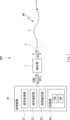
- FIG. 2 schematically shows the configuration of the processing apparatus 10.
- FIG. 3 shows the configuration of the processing apparatus according to the first embodiment in more detail.
- the processing device 10 has a signal acquisition unit 11 , a signal selection unit 12 , an interval estimation unit 13 and a storage unit 14 .
- the signal acquisition unit 11 receives the detection signals DET L and DET S output from the detection units 1 and 2, performs signal processing for conversion into a data format used for signal processing in the signal selection unit 12, and after processing, to the signal selection unit 12 .
- the signal selection unit 12 refers to the received signal group for the long gauge length section, selects the long gauge length section estimated to be closest to the sound source, and selects based on the gauge correspondence information TAB described later.
- the section estimating unit 13 refers to the signal group of the selected short gauge length sections, and determines the short gauge length section estimated to be closest to the sound source as the event section.
- the storage unit 14 stores gauge correspondence information TAB that specifies which short gauge length section corresponds to each long gauge length section, that is, a plurality of short gauge length sections included in one long gauge length section. is stored. Note that the storage unit 14 can also store other information, and the signal acquisition unit 11, the signal selection unit 12, and the interval estimation unit 13 appropriately read necessary information from the storage unit 14, and retrieve the necessary information. It is possible to write to the storage unit 14 .
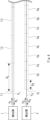
- FIG. 4 schematically shows gauges set on the optical fibers FL and FS .
- the optical fiber F L has a gauge length G L (hereinafter also referred to as a long gauge length) with a long gauge length section L 1 to L M (M is 2 or more) in a direction away from the detection unit 1. integer) is set.
- a short gauge length section S 1 to S N (N is an integer of 2 or more) of a gauge length G S (hereinafter also referred to as a short gauge length) is set in the optical fiber F S in a direction away from the detection unit 2. It is
- the long gauge length GL and the short gauge length GS can be arbitrary values.
- the long gauge length G L can be several tens of meters
- the short gauge length G S can be several tens of centimeters to several meters.
- Two adjacent long gauge length sections may be associated with short gauge length sections so as not to overlap, or may be associated with short gauge length sections so as to overlap.
- the long gauge length section L 1 has short gauge length sections S 1 to S 3
- the long gauge length section L 2 has short gauge length sections S 4 to S 6
- the long gauge length section L 3 may correspond to the short gauge length sections S 7 to S 9 .
- the short gauge length section S3 located at the boundary between the long gauge length section L1 and the long gauge length section L2 may be shared, and the long gauge length section L2 and the long gauge length section S3 may be shared. It may share a short gauge length section S 6 located at the boundary with section L 3 .
- the long gauge length section L2 includes a short gauge length section S3 shared with the long gauge length section L1 , short gauge length sections S4 and S5 , and a short gauge length shared with the long gauge length section L3.
- Section S6 will correspond. Note that the number of short gauge length sections shared by two adjacent long gauge length sections is not limited to one, and may be any number.
- the detection unit 1 receives return light from each of the long gauge length sections L 1 to L M and outputs detection results
- the detection unit 2 receives return light from each of the short gauge length sections S 1 to S N . It can receive light and output detection results.
- the processing device 10 can then appropriately analyze signals obtained from these detection results.
- the DAS system 100 uses a combination of a signal group obtained from return light from a plurality of long gauge length sections and a signal group obtained from return light from a plurality of short gauge length sections. , to specify the detailed position of the sound source.
- FIG. 5 shows an example of the relationship between gauge length and signal.
- the long gauge length section L and the corresponding short gauge length sections S_1 to S_3 are shown.
- a signal with high intensity and high SN (Signal to Noise) ratio is generally obtained from the return light from the long gauge length section. Therefore, when the sound wave AW reaches the optical fiber FL , the difference in signal strength between adjacent long-gauge length sections becomes relatively large, so the long-gauge length section close to the sound source can be easily identified.
- a signal with a low intensity and a low SN ratio is generally obtained from the return light from the short gauge long section. Therefore, even if the signal intensity of the return light from the short gauge length section is monitored, it is difficult to distinguish between the arrival of the sound wave and the fluctuation of the signal intensity due to a cause other than the sound wave because the signal intensity fluctuates so little.
- the DAS system 100 using the properties due to the difference in gauge length, when a sound wave reaches the optical fiber, first identify the long gauge length section closest to the sound source, and correspond to the identified long gauge length section. That is, by analyzing signals obtained from short gauge length sections provided at similar positions, the short gauge length section closest to the sound source is determined as the event section. Thereby, the DAS system 100 can determine the position (event position) closest to the sound source with high accuracy.
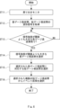
- FIG. 6 shows a flowchart of the event section determination operation in the DAS system 100. As shown in FIG.
- Step ST11 The detector 1 outputs a light pulse PL to the optical fiber FL and monitors the return light RL .
- a detection signal DET L obtained by photoelectrically converting the return light RL is output to the processing device 10 .
- the detector 2 outputs an optical pulse PS to the optical fiber FS and monitors the return light RS . Then, the return light RS is photoelectrically converted and output to the detection signal DETS processing device 10 .
- Step ST12 The signal acquisition unit 11 acquires a signal group in the long gauge length section based on the detection signal DET L , and outputs the acquired signal group to the signal selection unit 12 .
- the signal acquisition unit 11 also acquires a signal group in the short gauge length section based on the detection signal DET L , and outputs the acquired signal group to the signal selection unit 12 .
- Step ST13 The signal selection unit 12 monitors the signal group acquired for each long gauge length section, and determines whether or not there is a long gauge length section in which the first feature amount is greater than the threshold.
- the signal intensity of each long gauge length section is used as the first feature amount of each long gauge length section will be described.
- the signal selection unit 12 monitors a group of signals acquired for each long gauge length section, and determines whether or not there is a long gauge length section in which variation in signal intensity is greater than a threshold.
- Step ST14 When there is a long gauge length section in which the fluctuation of the first feature amount is greater than the threshold, the signal selection unit 12 selects the long gauge length section as an event-generated long gauge length section such as arrival of a sound wave.
- Step ST15 The signal selection unit 12 selects a plurality of short gauge length sections corresponding to the selected long gauge length section.
- a plurality of short gauge length sections corresponding to each of the long gauge length sections are determined in advance, and gauge correspondence information TAB corresponding to the short gauge length sections may be stored in advance in the storage unit 14 as, for example, a data table. good.
- the signal selection unit 12 can refer to the gauge correspondence information TAB as necessary to select a plurality of short gauge length sections corresponding to the selected long gauge length section.
- Step ST16 The interval estimating unit 13 selects a short gauge length interval (hereinafter referred to as event interval ).
- event interval a short gauge length interval
- the processing device 10 acquires the maximum intensity value from each of the waveforms of two or more short gauge length sections, and selects the short gauge length section with the largest maximum value as the event section.
- the signal to be used may be a time waveform signal, or a signal obtained by subjecting the time waveform signal to predetermined processing.
- the degree of similarity may be calculated using a signal to which a low-pass filter has been applied or a signal to which noise suppression processing has been performed for the time waveform signal.
- a so-called spectrogram which is a signal in the time and frequency domain obtained by converting a time waveform signal by Fourier transform or CQT (Constant Q Conversion), may be used.
- the converted signal not only the converted signal itself, but also the binarized signal obtained by subjecting the intensity of the converted waveform signal to discrimination processing using a predetermined threshold value, and the edge signal for emphasizing a point where the intensity changes steeply.
- a signal obtained by subjecting the converted signal to predetermined signal processing such as a signal to which an enhancement filter is applied, may be used.
- a so-called spectrogram may also be used.
- An index indicating the difference between the waveform signal acquired for the selected long gauge length section and the waveform signal acquired for each short gauge length section may be used to calculate the degree of similarity.
- the feature quantity is a multi-dimensional quantity such as a distribution of data points or a vector quantity
- various indexes such as cross-correlation, correlation coefficient, Mahalabinos distance, cosine distance, and Pearson's product-moment correlation coefficient are used as indicators of differences. indicators can be used.
- an index such as the difference between two values or the absolute value of the difference can be used.
- the principal component obtained by performing principal component analysis on the time waveform signal or the signal in the time and frequency domain, or the Mel-frequency cepstrum coefficient of the signal in the time and frequency domain may be used.
- the event section can be determined in detail. position can be narrowed down. That is, the event period can be determined with high spatial resolution.
- the SN ratio of the signal obtained by the occurrence of the event is low, and it is generally difficult to determine whether the signal fluctuation is due to the event or the influence of noise etc. .
- the general position where the event occurred is specified by using the long gauge length section in which a signal with a high SN ratio is obtained. As a result, it can be determined that the intensity fluctuation appearing in the signal of the short gauge length section corresponding to the specified long gauge length section is due to the event, so that the short gauge length section in which the event occurred can be determined with high accuracy. It becomes possible.
- Embodiment 2 In the first embodiment, an example in which one of the two optical fibers is set as the long gauge length section and the other is set as the short gauge length section has been described. Other configurations are possible as long as the constellation of signals is obtained. Another configuration of the DAS system capable of obtaining a group of signals in the long gauge length section and a group of signals in the short gauge length section will be described below.
- FIG. 7 schematically shows the configuration of the DAS system 200 according to the second embodiment.
- the DAS system 200 has a processor 2, a detector 1 and an optical fiber F.
- the detector 1 outputs a light pulse P to the optical fiber F, and monitors the return light R from the gauge section having a predetermined gauge length set in the optical fiber F. be able to. Thereby, a group of signals obtained for a plurality of gauge sections can be acquired.
- the processing device 2 is configured to be able to convert the acquired signal group into signals of different gauge length sections by performing predetermined signal processing.
- the signal acquisition unit 21, the signal selection unit 22, the interval estimation unit 23, and the storage unit 24 of the processing device 2 correspond to the signal acquisition unit 11, the signal selection unit 12, the interval estimation unit 13, and the storage unit 14 of the processing device 1, respectively. .
- FIG. 8 shows a flowchart of the event section determination operation of the DAS system 200 according to the second embodiment.
- step ST12 of FIG. 6 is replaced with steps ST21 and ST22.
- Step ST21 The signal acquisition unit 21 acquires a signal group corresponding to the long gauge length section.
- Step ST22 The signal acquisition unit 21 performs signal processing on the signal group corresponding to the long gauge length section based on the signal processing condition INF read from the storage unit 24, and acquires the signal group corresponding to the short gauge length section. .
- steps ST11, ST13 to ST16 are the same as in FIG. 6, so the description is omitted.
- the signal processing conditions in this configuration can be determined by performing the initialization process as follows. First, a known sound source is set in advance in the vicinity of the optical fiber F, and a known sound wave is applied to the optical fiber F to obtain a signal group for the long gauge length section. After that, a short gauge length section is set on the optical fiber, and a known sound wave is applied again to acquire a signal group for the short gauge length section. Then, the signal processing conditions are obtained by comparing the two obtained signal groups and performing initial setting processing to set the conditions for converting the signal in the long gauge length section to obtain the signal in the short gauge length section. and stored in the storage unit 24 as the signal processing condition INF.
- a short gauge length section may be set in the optical fiber F, and a signal group obtained for the short gauge length section by signal processing may be converted into a signal group for the long gauge length section. Even in this case, the signal processing conditions can be acquired in the same manner as described above.
- the detection section may be provided with two light receiving sections, and the return light from the optical fiber F may be distributed to the two light receiving sections.
- a signal group for the long gauge length section is obtained from the signal output from one light receiving section, and the signal group is output from the other light receiving section. It is possible to obtain a group of signals for a short gauge length section from the signals. Therefore, similarly, every time an optical pulse is output, a signal group for the long gauge length section and a signal group for the short gauge length section from the signal output from the other light receiving section can be obtained simultaneously. .
- Embodiment 3 A DAS system according to the third embodiment will be described.
- a DAS system 300 according to the third embodiment is configured as a modification of the DAS system 200.
- FIG. FIG. 9 schematically shows the configuration of a DAS system 300 according to the third embodiment.
- the DAS system 300 has a processor 3, a detector 1 and an optical fiber F.
- the processing device 3 is configured to be able to acquire a signal group of the long gauge length section and a signal group of the short gauge length section by switching the gauge length as described later.
- the signal acquisition unit 31, the signal selection unit 32, the interval estimation unit 33, and the storage unit 34 of the processing device 3 correspond to the signal acquisition unit 11, the signal selection unit 12, the interval estimation unit 13, and the storage unit 14 of the processing device 1, respectively. .
- a long gauge length section and a short gauge length section are alternately set in the optical fiber F in a time division manner. That is, it is possible to alternately perform the process of acquiring the signal group with the long gauge length section set and the process of acquiring the signal group with the short gauge length section set.
- FIG. 10 shows a flowchart of the event section determination operation of the DAS system 300 according to the third embodiment.
- steps ST11 and ST12 of FIG. 6 are replaced with steps ST31 to ST36.
- Step ST31 The signal acquisition unit 31 first sets a plurality of long gauge length sections on the optical fiber F. As shown in FIG.
- Step ST32 The detector 1 outputs a light pulse P to the optical fiber F and monitors the return light R.
- FIG. A detection signal DET obtained by photoelectrically converting the return light R is output to the processing device 10 .
- Step ST33 The signal acquisition unit 31 acquires a signal group of the long gauge length section based on the detection signal DET, and stores the acquired signal group in the storage unit 34, for example, as long gauge length section signal group information SIG L.
- Step ST34 The signal acquisition unit 31 sets a plurality of short gauge length sections in the optical fiber F by switching the gauge length.
- Step ST35 The detector 1 outputs a light pulse P to the optical fiber F and monitors the return light R.
- FIG. A detection signal DET obtained by photoelectrically converting the return light R is output to the processing device 10 .
- Step ST36 The signal acquisition unit 31 acquires a signal group in the short gauge length section based on the detection signal DET, and stores the acquired signal group in the storage unit 34, for example, as short gauge length section signal group information SIGS .
- steps ST13 to ST16 are the same as in FIG. 6, so the description is omitted.
- event intervals can be determined with high spatial resolution, as in the first and second embodiments.
- Embodiment 4 In Embodiment 1, only one long gauge length section is selected, and a plurality of short gauge length sections close to the sound source are determined from a plurality of short gauge length sections corresponding to the selected one long gauge length section. However, if an event occurs in two long gauge length sections, it would be better to determine a plurality of short gauge length sections that are closer to the sound source from the short gauge length sections corresponding to these two long gauge length sections. obtain.
- a DAS system that determines a plurality of short gauge length sections near the sound source from short gauge length sections corresponding to two long gauge length sections will be described.
- FIG. 11 schematically shows the configuration of a DAS system 400 according to the fourth embodiment.
- the DAS system 400 has a configuration in which the processing device 1 of the DAS system 100 is replaced with a processing device 4 .
- the detectors 1 and 2 and the optical fibers FL and FS are the same as those of the DAS system 100, so their description is omitted.
- the signal acquisition unit 41, the signal selection unit 42, the interval estimation unit 43, and the storage unit 44 of the processing device 4 correspond to the signal acquisition unit 11, the signal selection unit 12, the interval estimation unit 13, and the storage unit 14 of the processing device 1, respectively. .
- the 400 operation of the DAS system will be described below.
- event sections exist in adjacent long gauge length sections, they are the same event, that is, caused by the same sound wave. is determined, and processing is performed to update the event section information as necessary.
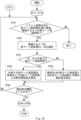
- FIGS. 12 and 13 show flowcharts of the event section information update operation of the DAS system 400 according to the fourth embodiment. Each step in FIGS. 12 and 13 is performed after steps ST11 to ST16 in FIG. 6 are completed.
- the long gauge long section signal group information SIG L the short gauge long section signal group information SIG S , and the short gauge which is the event section are obtained in advance.
- Event section information EVT which is information indicating a long section, is stored.
- Step ST41 The signal acquisition unit 41 refers to the event interval information EVT and the gauge correspondence information TAB, and sequentially from the detection unit 1 side, searches for locations where an event interval exists in each of two adjacent long gauge length intervals. If there is no place where the event section exists in each of the two adjacent long gauge length sections, the process ends.
- Step ST42 If there is a place where an event section exists in each of the two adjacent long gauge length sections, the signal selection unit 42 selects the two adjacent long gauge length sections LA and LB that have been found, and divides the selection result into the section It is passed to the estimation unit 43 .
- Step ST43 As described in Embodiment 1, the section estimation unit 43 calculates the similarity between the long gauge length sections LA and LB, and determines whether the calculated similarity is greater than a predetermined threshold. The degree of similarity between the long gauge length sections LA and LB is calculated, and if the degree of similarity calculated is equal to or less than a predetermined threshold value, the process returns to step ST41. Accordingly, when the similarity is small, it can be understood that the signal groups of the long gauge long sections LA and LB are dissimilar, and it is determined that they are separate events.
- Step ST44 When the degree of similarity calculated in step ST43 is greater than the predetermined threshold, the section estimation unit 43 deletes the event sections of the long gauge length sections LA and LB. Specifically, the interval estimating unit 43 accesses the storage unit 44 and deletes the event intervals of the long gauge length intervals LA and LB from the event interval information EVT.
- Step ST45 The signal selection unit 42 selects a plurality of short gauge length sections corresponding to the long gauge length section LA.
- Step ST46 The interval estimating unit 43 determines the event interval, which is the short gauge length interval in which the strongest sound wave is estimated to arrive, based on the feature values of each of the plurality of short gauge length intervals corresponding to the long gauge length interval LA. Select a candidate SA.
- Step ST47 The signal selection unit 42 selects a plurality of short gauge length sections corresponding to the long gauge length section LB.
- Step ST48 The interval estimating unit 43 determines the event interval, which is the short gauge length interval in which the strongest sound wave is estimated to have arrived, based on the feature values of each of the plurality of short gauge length intervals corresponding to the long gauge length interval LB. Select a candidate SB.
- Step ST49 The section estimation unit 43 calculates the degree of similarity between the long gauge length section LA and the event section candidate SA, and the degree of similarity between the long gauge length section LB and the event section candidate SB. Then, it is determined whether the similarity between the long gauge length section LA and the event section candidate SA is greater than or equal to the similarity between the long gauge length section LB and the event section candidate SB.
- Step ST50 If the degree of similarity between the long gauge length section LA and the event section candidate SA is greater than or equal to the degree of similarity between the long gauge length section LB and the event section candidate SB, the event section candidate SA is determined as an event section, and an event Update the section information EVT. After that, the process is returned to step ST41.
- Step ST51 If the similarity between the long gauge length section LA and the event section candidate SA is smaller than the similarity between the long gauge length section LB and the event section candidate SB, the event section candidate SB is determined as the event section, and the event Update the section information EVT. After that, the process is returned to step ST41.
- FIG. 14 shows a flowchart for determining the similarity of events based on the similarity of short gauge length sections corresponding to two adjacent long gauge length sections.
- step ST43 of FIG. 12 is replaced with steps ST61 to ST64.
- Step ST61 The section estimation unit 43 determines whether there is a short gauge length section shared by the long gauge length sections LA and LB.
- sharing of the short gauge length section will be described.
- FIG. 15 shows an example in which the long gauge length sections LA and LB share a short gauge length section.
- the short gauge length section SSH existing across the boundary BND between the long gauge length sections LA and LB is a short gauge length section corresponding to both the long gauge length sections LA and LB.
- FIG. 16 shows an example in which the long gauge length sections LA and LB do not have a shared short gauge length section.
- each of the long gauge length sections LA and LB corresponds to its own short gauge length section, and there is no short gauge length section corresponding to both.
- Step ST62 When there is a short gauge length section shared by the long gauge length sections LA and LB, the section estimation unit 43 determines the short gauge length section corresponding to the long gauge length section LA adjacent to the shared short gauge length section SSH .
- the similarity between Sa and the short gauge length section Sb corresponding to the long gauge length section LB is calculated.
- the short gauge length section Sa is the short gauge length closest to the long gauge length section LB among the plurality of short gauge length sections corresponding to the long gauge length section LA, other than the shared short gauge length section SH .
- the short gauge length section Sb is the short gauge length section closest to the long gauge length section LA among the plurality of short gauge length sections corresponding to the long gauge length section LB, other than the shared short gauge length section SH . be.
- Step ST63 When there is no short gauge length section shared by the long gauge long sections LA and LB, the section estimation unit 43 determines the short gauge length adjacent to the long gauge long section LB among the plurality of short gauge length sections corresponding to the long gauge long section LA. The degree of similarity between the gauge length section Sa and the short gauge length section b adjacent to the long gauge length section LA among the plurality of short gauge length sections corresponding to the long gauge length section LB is calculated.
- Step ST64 The section estimator 43 determines whether the degree of similarity between the short gauge length section Sa and the short gauge length section Sb is greater than a predetermined threshold. If the degree of similarity is greater than the predetermined threshold, the process proceeds to step ST44, and if the degree of similarity is equal to or less than the predetermined threshold, the process returns to step ST41.
- the DAS system 100 according to the first embodiment has been described above, this is merely an example. Needless to say, the DAS system according to the second and third embodiments can be applied as long as the signal group of the long gauge length section and the signal group of the short gauge length section can be used.
- the step of determining the magnitude relationship between the two values a and b has been described.
- the present invention has been described as a hardware configuration in the above embodiment, the present invention is not limited to this.
- the present invention can also be realized by causing a CPU (Central Processing Unit) to execute a computer program to perform processing in the processing device.
- the above-described program can be stored and supplied to a computer using various types of non-transitory computer readable media.
- Non-transitory computer-readable media include various types of tangible storage media.
- non-transitory computer-readable media examples include magnetic recording media (eg, flexible discs, magnetic tapes, hard disk drives), magneto-optical recording media (eg, magneto-optical discs), CD-ROM (Read Only Memory) CD-R, CD - R/W, including semiconductor memory (eg, mask ROM, PROM (Programmable ROM), EPROM (Erasable PROM), flash ROM, RAM (Random Access Memory)).
- the program may also be supplied to the computer on various types of transitory computer readable medium. Examples of transitory computer-readable media include electrical signals, optical signals, and electromagnetic waves. Transitory computer-readable media can deliver the program to the computer via wired channels, such as wires and optical fibers, or wireless channels.
- the signal selection unit compares each signal of the selected short gauge length section with the signal of the selected long gauge length section, and compares the signal of the selected long gauge length section. 2. The processing unit of claim 1, wherein the short gauge length interval having a signal that most closely matches the signal is determined as the interval where the event occurred.
- the signal selection unit selects, as the signal, a time waveform signal, a waveform signal obtained by applying a frequency filter to the time waveform signal, a waveform signal subjected to noise suppression processing of the time waveform signal, and the time waveform.
- the processing device which uses any one of a signal obtained by Fourier transforming a signal, a signal obtained by converting the time waveform signal by CQT (Constant Q Conversion), and a spectrogram obtained from the time waveform signal.
- the signal selection unit performs principal component analysis on each of the selected short gauge length sections or the waveform signal obtained by converting the time waveform signal. Alternatively, the section in which the event occurred is determined based on the mel-frequency cepstrum coefficients of the time waveform signal of each of the selected short gauge length sections or a waveform signal obtained by converting the time waveform signal. 2.
- the processing apparatus according to 1.
- Appendix 5 The processing device according to any one of Appendices 1 to 4, wherein the signal selection unit selects a long gauge length section in which the first feature amount is greater than a first threshold.
- Supplementary note 6 Any one of Supplementary notes 1 to 5, wherein the signal selection unit determines, from among the plurality of selected short gauge length sections, the section having the largest first feature value as the section in which the event occurs. 1.
- a processing device according to claim 1.
- the signal selection unit selects a long gauge length section in which the first feature amount is greater than a first threshold, and among the plurality of selected short gauge length sections, the first feature amount is determined as the section in which the event occurs.
- the signal acquisition unit acquires a signal group by setting one of the plurality of long gauge length sections and the plurality of short gauge length sections in one optical fiber, and a predetermined 8.
- the processing device according to any one of appendices 1 to 7, wherein the other signal group of the plurality of long gauge length sections and the plurality of short gauge length sections is obtained by performing signal processing.
- the signal acquisition unit performs a process of setting the plurality of long gauge length sections in one optical fiber and acquiring a signal group of the plurality of long gauge length sections, and 8.
- the processing device according to any one of appendices 1 to 7, wherein the processing of setting the plurality of short gauge length sections and acquiring the signal groups of the plurality of short gauge length sections are alternately performed.
- the degree of similarity indicating the degree of similarity, and the degree of similarity between the signal in the second long gauge length section, which is the other of the two adjacent long gauge length sections, and the signal of the event candidate in the second long gauge length section. are compared, and the event candidate in the long gauge section with the greater similarity is replaced with the section in which the event occurred in the first and second long gauge length sections, and newly, 11.
- the signal of the second long gauge length section, which is the other of the two long gauge length sections that are the other of the two long gauge length sections, is compared with a similarity indicating the degree of similarity to the signal of the event candidate of the second long gauge length section, and the similarity wherein the event candidate of the long gauge section with the larger degree is newly determined as the section in which the event occurs instead of the event occurrence section of the first and second long gauge length sections.
- An optical fiber used for sensing a detection unit that outputs a light pulse to the optical fiber and monitors the return light, and a processing device that receives the monitoring result of the return light from the detection unit. wherein the processing device acquires a plurality of signal groups based on returned light from a plurality of long gauge length sections and a plurality of returned light from a plurality of short gauge length sections set in the optical fiber.
- a distributed acoustic sensing system comprising: a section estimator that determines the section in which
Abstract
信号取得部(11)は、分布型音響センシングに用いられる光ファイバに設定した、複数の長ゲージ長区間からの戻り光に基づいて取得した複数の信号群と、複数の短ゲージ長区間からの戻り光に基づいて取得した複数の信号群とを取得する。信号選択部(12)は、複数の長ゲージ長区間の信号群のそれぞれの第1の特徴量に基づいて長ゲージ長区間を選択し、選択した前記長ゲージ長区間に対応する複数の短ゲージ長区間を選択する。区間推定部(13)は、選択された複数の短ゲージ長区間の信号群のそれぞれの第2の特徴量に基づいて、1つの短ゲージ長区間を、イベントが発生した区間として決定する。
Description
本発明は、処理装置、分布型音響センシングシステム、分布型音響センシング方法及びプログラムが格納された非一時的なコンピュータ可読媒体に関する。
光ファイバセンシング技術の一つとして、分布型音響センシング(Distributed acoustic sensing:DAS)が知られている。DASでは、光ファイバに音波が当たると光ファイバを通過する光が変調されるため、その反射光または透過光を検波することで、遠隔地の音波ないしは振動をモニタすることができる。
DASシステムは、一般に、音や振動を感じる光ファイバとインテロゲータ(Interrogator)と呼ばれる検出部とで構成される。インテロゲータは「問い合わせる者」の意味で、光ファイバにプローブ光を当て、光ファイバからの反射光又は透過光を受光し、光ファイバに作用する音波や振動の状態を検出する(特許文献1~3)。
DASシステムでのセンシングには、検出する現象(以下、イベントと称する)の詳細な位置を特定するのが難しいという問題がある。DASシステムでは、対象領域に敷設した光ケーブルに含まれる光ファイバに、所定のゲージ長を有する区間を設定し、区間内で生じた音や振動の状態を信号として計測した後にいずれの区間の近傍でイベントが生じたかを検出する。この場合、一般に、長いゲージ長の区間からの戻り光から得られる信号は強度が大きく、SN(Signal to Noise)比が高い信号が得られる。そのため、イベントの発生を容易に検出できるものの、ゲージ長が長いため、イベント発生の位置が長い区間内のどこであるかまでは特定できない。これに対し、短いゲージ長の区間からの戻り光から得られる信号は強度が小さく、SN比が低い信号が得られる。そのため、信号の変動がイベント発生によるものか雑音等によるものかの判別が困難であり、イベント検出精度が劣る。そのため、イベント検出の空間分解能を向上させるためにゲージ長を短くしても、イベントを好適に検出することは困難である。
本発明は、上記の事情に鑑みて成されたものであり、分布型音響センシングシステムにおいて高い空間分解能にてイベントの発生を検出することを目的とする。
本発明の一態様である処理装置は、分布型音響センシングに用いられる光ファイバに設定した、複数の長ゲージ長区間からの戻り光に基づいて取得した複数の信号群と、複数の短ゲージ長区間からの戻り光に基づいて取得した複数の信号群とを取得する信号取得部と、複数の前記長ゲージ長区間の信号群のそれぞれの第1の特徴量に基づいて長ゲージ長区間を選択し、選択した前記長ゲージ長区間に対応する複数の短ゲージ長区間を選択する信号選択部と、選択された前記複数の短ゲージ長区間の信号群のそれぞれの第2の特徴量に基づいて、1つの短ゲージ長区間を、イベントが発生した区間として決定する区間推定部と、を備えるものである。
本発明の一態様である分布型音響センシングシステムは、センシングに用いられる光ファイバと、前記光ファイバに光パルスを出力してその戻り光をモニタする検出部と、前記検出部での前記戻り光のモニタ結果を受け取る処理装置と、を備え、前記処理装置は、前記光ファイバに設定した、複数の長ゲージ長区間からの戻り光に基づいて取得した複数の信号群と、複数の短ゲージ長区間からの戻り光に基づいて取得した複数の信号群とを取得する信号取得部と、複数の前記長ゲージ長区間の信号群のそれぞれの第1の特徴量に基づいて長ゲージ長区間を選択し、選択した前記長ゲージ長区間に対応する複数の短ゲージ長区間を選択する信号選択部と、選択された前記複数の短ゲージ長区間の信号群のそれぞれの第2の特徴量に基づいて、1つの短ゲージ長区間を、イベントが発生した区間として決定する区間推定部と、を備えるものである。
本発明の一態様である分布型音響センシング方法は、分布型音響センシングに用いられる光ファイバに設定した、複数の長ゲージ長区間からの戻り光に基づいて取得した複数の信号群と、複数の短ゲージ長区間からの戻り光に基づいて取得した複数の信号群とを取得し、複数の前記長ゲージ長区間の信号群のそれぞれの第1の特徴量に基づいて長ゲージ長区間を選択し、選択した前記長ゲージ長区間に対応する複数の短ゲージ長区間を選択し、選択された前記複数の短ゲージ長区間の信号群のそれぞれの第2の特徴量に基づいて、1つの短ゲージ長区間を、イベントが発生した区間として決定するものである。
本発明の一態様であるプログラムが格納された非一時的なコンピュータ可読媒体は、分布型音響センシングに用いられる光ファイバに設定した、複数の長ゲージ長区間からの戻り光に基づいて取得した複数の信号群と、複数の短ゲージ長区間からの戻り光に基づいて取得した複数の信号群とを取得する処理と、複数の前記長ゲージ長区間の信号群のそれぞれの第1の特徴量に基づいて長ゲージ長区間を選択し、選択した前記長ゲージ長区間に対応する複数の短ゲージ長区間を選択する処理と、選択された前記複数の短ゲージ長区間の信号群のそれぞれの第2の特徴量に基づいて、1つの短ゲージ長区間を、イベントが発生した区間として決定する処理と、をコンピュータに実行させるものである。
本発明によれば、分布型音響センシングシステムにおいて高い空間分解能にてイベントの発生を検出することができる。
以下、図面を参照して本発明の実施の形態について説明する。各図面においては、同一要素には同一の符号が付されており、必要に応じて重複説明は省略される。
実施の形態1
実施の形態1にかかるDASシステムについて説明する。図1に、実施の形態1にかかるDASシステム100の構成を模式的に示す。DASシステム100は、検出部1及び2、処理装置10及び光ファイバFL及びFSを有する。処理装置10は、制御信号COMLによって検出部1を制御し、制御信号COMSによって検出部2を制御するように構成される。また、処理装置10は、検出部1から検出結果を示す検出信号DETLを受け取り、検出部2から検出結果を示す検出信号DETSを受け取り、これらに音響センシングに要する信号処理を行うものとして構成される。
実施の形態1にかかるDASシステムについて説明する。図1に、実施の形態1にかかるDASシステム100の構成を模式的に示す。DASシステム100は、検出部1及び2、処理装置10及び光ファイバFL及びFSを有する。処理装置10は、制御信号COMLによって検出部1を制御し、制御信号COMSによって検出部2を制御するように構成される。また、処理装置10は、検出部1から検出結果を示す検出信号DETLを受け取り、検出部2から検出結果を示す検出信号DETSを受け取り、これらに音響センシングに要する信号処理を行うものとして構成される。
光ファイバFL及びFSは、音波AWのセンシングの対象となる領域の同じ又は近接した経路に敷設されるものであり、例えば、海底ケーブルなどの光ケーブルCに同梱されるファイバである。
検出部1は、光ファイバFLと接続され、光ファイバFLへ光パルスPLを出力し、光ファイバFLにおける後方散乱光である戻り光RLを検出する、いわゆるインテロゲータとして構成される。検出部1は、戻り光RLの検出結果である検出信号DETLを処理装置10へ出力する。
検出部2は、光ファイバFSと接続され、光ファイバFSへ光パルスPSを出力し、光ファイバFSにおける後方散乱光である戻り光RSを検出する、いわゆるインテロゲータとして構成される。検出部2は、戻り光RSの検出結果である検出信号DETSを処理装置10へ出力する。
図2に、処理装置10の構成を模式的に示す。また、図3に、実施の形態1にかかる処理装置の構成をより詳細に示す。処理装置10は、信号取得部11、信号選択部12、区間推定部13及び記憶部14を有する。信号取得部11は、検出部1及び2から出力される検出信号DETL及びDETSを受け取り、信号選択部12での信号処理に用いられるデータ形式へ変換するための信号処理を行い、処理後の信号を信号選択部12へ出力する。信号選択部12は、受け取った長ゲージ長区間についての信号群を参照し、音源に最も近いと推定される長ゲージ長区間を選択し、かつ、後述するゲージ対応情報TABに基づいて、選択された長ゲージ長区間に対応する複数の短ゲージ長区間を選択する。区間推定部13は、選択された複数の短ゲージ長区間の信号群を参照して、音源に最も近いと推定される短ゲージ長区間をイベント区間として決定する。記憶部14には、各長ゲージ長区間にどの短ゲージ長区間が対応しているか、すなわち、1つの長ゲージ長区間に包含される複数の短ゲージ長区間が指定された、ゲージ対応情報TABが格納されている。なお、記憶部14には他の情報も格納可能であり、信号取得部11、信号選択部12及び区間推定部13は、適宜、必要な情報を記憶部14から読み出し、かつ、必要な情報を記憶部14に書き込み可能である。
本実施の形態では、光ファイバFL及びFSにはそれぞれ異なる長さのゲージが設定される。図4に、光ファイバFL及びFSに設定されるゲージを模式的に示す。この例では、光ファイバFLに、検出部1から遠ざかる方向に向けて、ゲージ長GL(以下、長ゲージ長とも称する)の長ゲージ長区間L1~LM(Mは、2以上の整数)が設定されている。光ファイバFSに、検出部2から遠ざかる方向に向けて、ゲージ長GS(以下、短ゲージ長とも称する)の短ゲージ長区間S1~SN(Nは、2以上の整数)が設定されている。
長ゲージ長GLは短ゲージ長GSよりも長く、図4では、一例として、長ゲージ長GLは短長ゲージ長GSの3倍(GL=3GS)としている。但し、これは例示に過ぎず、長ゲージ長GLが短ゲージ長GSよりも長い限り、長ゲージ長GL及び短ゲージ長GSは任意の値とすることができる。例えば、長ゲージ長GLは数十m、短ゲージ長GSは数十cm~数mとすることができる。
なお、隣接する2つの長ゲージ長区間に対しては、重複しないように短ゲージ長区間を対応させてもよいし、重複するように短ゲージ長区間を対応させてもよい。例えば、図4において、重複しないように、長ゲージ長区間L1に短ゲージ長区間S1~S3、長ゲージ長区間L2に短ゲージ長区間S4~S6、長ゲージ長区間L3に短ゲージ長区間S7~S9に対応させてもよい。また、例えば、図4において、長ゲージ長区間L1と長ゲージ長区間L2との境界に位置する短ゲージ長区間S3を共有してもよく、長ゲージ長区間L2と長ゲージ長区間L3との境界に位置する短ゲージ長区間S6を共有してもよい。この場合、長ゲージ長区間L2には、長ゲージ長区間L1と共有する短ゲージ長区間S3、短ゲージ長区間S4及びS5、長ゲージ長区間L3と共有する短ゲージ長区間S6が対応することとなる。なお、隣接する2つの長ゲージ長区間が共有する短ゲージ長区間は1つに限られず、任意の数としてもよい。
これにより、検出部1は長ゲージ長区間L1~LMのそれぞれからの戻り光を受け取って検出結果を出力し、検出部2は、短ゲージ長区間S1~SNのそれぞれからの戻り光を受け取って検出結果を出力することができる。そして、処理装置10は、これらの検出結果から得られる信号を適宜分析することができる。
本実施の形態にかかるDASシステム100は、複数の長ゲージ長区間からの戻り光から得られる信号群と、複数の短ゲージ長区間からの戻り光から得られる信号群とを組み合わせて用いることで、音源の詳細位置を特定するものとして構成される。
DASシステムにおける光ファイバに音波AWが到達した場合の戻り光を解析すると、一般に、長ゲージ長の区間からの戻り光から得られる信号と、短ゲージ長の区間からの戻り光から得られる信号とには、差異が生じる。図5に、ゲージ長と信号との関係の例を示す。ここでは、例として、長ゲージ長区間Lとこれに対応する短ゲージ長区間S_1~S_3に着目し、これらから得られる信号SIG_L、SIG_S_1~SIGS_3の周波数領域での波形を示している。長ゲージ長区間からの戻り光からは、一般に、強度が大きく、SN(Signal to Noise)比が高い信号が得られる。このため、光ファイバFLに音波AWが到達した場合、隣接する長ゲージ長区間の信号強度の差は比較的大きくなるので、音源に近い長ゲージ長区間を容易に識別することができる。
これに対し、短ゲージ長区間からの戻り光からは、一般に、強度が小さく、SN比が低い信号が得られる。このため、短ゲージ長区間からの戻り光の信号強度をモニタしても、音波が到達した場合と音波以外の原因で信号強度が変動した場合の信号強度の変動が小さく、判別が難しい。
DASシステム100では、ゲージ長の違いによる性質を利用して、光ファイバに音波が到達した場合に、まず音源に一番近い長ゲージ長区間を特定し、特定した長ゲージ長区間に対応する、すなわち、同様の位置に設けられている短ゲージ長区間から得られる信号を解析することで、音源に一番近い短ゲージ長区間をイベント区間として決定する。これにより、DASシステム100は、音源に一番近い位置(イベント位置)を、高精度に決定することができる。
以下、DASシステム100におけるイベント位置決定動作について説明する。図6に、DASシステム100におけるイベント区間決定動作のフローチャートを示す。
ステップST11
検出部1は、光ファイバFLに光パルスPLを出力して、戻り光RLをモニタする。そして、戻り光RLを光電変換した検出信号DETLを処理装置10へ出力する。検出部2は、光ファイバFSに光パルスPSを出力し、戻り光RSをモニタする。そして、戻り光RSを光電変換した検出信号DETS処理装置10へ出力する。
検出部1は、光ファイバFLに光パルスPLを出力して、戻り光RLをモニタする。そして、戻り光RLを光電変換した検出信号DETLを処理装置10へ出力する。検出部2は、光ファイバFSに光パルスPSを出力し、戻り光RSをモニタする。そして、戻り光RSを光電変換した検出信号DETS処理装置10へ出力する。
ステップST12
信号取得部11は、検出信号DETLに基づいて長ゲージ長区間の信号群を取得し、取得した信号群を信号選択部12へ出力する。また、信号取得部11は、検出信号DETLに基づいて短ゲージ長区間の信号群を取得し、取得した信号群を信号選択部12へ出力する。
信号取得部11は、検出信号DETLに基づいて長ゲージ長区間の信号群を取得し、取得した信号群を信号選択部12へ出力する。また、信号取得部11は、検出信号DETLに基づいて短ゲージ長区間の信号群を取得し、取得した信号群を信号選択部12へ出力する。
ステップST13
信号選択部12は、各長ゲージ長区間について取得した信号群をモニタし、第1の特徴量が閾値よりも大きな長ゲージ長区間が有るか判定する。ここでは、各長ゲージ長区間の信号強度を、各長ゲージ長区間の第1の特徴量として用いる例について説明する。信号選択部12は、各長ゲージ長区間について取得した信号群をモニタし、信号強度の変動が閾値よりも大きな長ゲージ長区間が有るか判定する。
信号選択部12は、各長ゲージ長区間について取得した信号群をモニタし、第1の特徴量が閾値よりも大きな長ゲージ長区間が有るか判定する。ここでは、各長ゲージ長区間の信号強度を、各長ゲージ長区間の第1の特徴量として用いる例について説明する。信号選択部12は、各長ゲージ長区間について取得した信号群をモニタし、信号強度の変動が閾値よりも大きな長ゲージ長区間が有るか判定する。
ステップST14
信号選択部12は、第1の特徴量の変動が閾値よりも大きな長ゲージ長区間が有る場合、その長ゲージ長区間を、音波が到達するなどのイベント発生した長ゲージ長区間として選択する。
信号選択部12は、第1の特徴量の変動が閾値よりも大きな長ゲージ長区間が有る場合、その長ゲージ長区間を、音波が到達するなどのイベント発生した長ゲージ長区間として選択する。
ステップST15
信号選択部12は、選択された長ゲージ長区間に対応する複数の短ゲージ長区間を選択する。ここで、長ゲージ長区間のそれぞれに対応する複数の短ゲージ長区間は予め決定されており、その対応情報であるゲージ対応情報TABは、例えばデータテーブルとして記憶部14に予め格納されていてもよい。信号選択部12は、必要に応じてゲージ対応情報TABを参照して、選択された長ゲージ長区間に対応する複数の短ゲージ長区間を選択することができる。
信号選択部12は、選択された長ゲージ長区間に対応する複数の短ゲージ長区間を選択する。ここで、長ゲージ長区間のそれぞれに対応する複数の短ゲージ長区間は予め決定されており、その対応情報であるゲージ対応情報TABは、例えばデータテーブルとして記憶部14に予め格納されていてもよい。信号選択部12は、必要に応じてゲージ対応情報TABを参照して、選択された長ゲージ長区間に対応する複数の短ゲージ長区間を選択することができる。
ステップST16
区間推定部13は、選択された2つ以上の短ゲージ長区間のそれぞれの第2の特徴量に基づいて、最も強度が大きな音波が到達したと推定される短ゲージ長区間(以下、イベント区間と称する)を選択する。ここでは、各短ゲージ長区間の信号強度の最大値を、各短ゲージ長区間の第2の特徴量として用いる例について説明する。処理装置10は、2つ以上の短ゲージ長区間の波形のそれぞれから強度の最大値を取得し、最大値が最も大きな短ゲージ長区間をイベント区間として選択する。
区間推定部13は、選択された2つ以上の短ゲージ長区間のそれぞれの第2の特徴量に基づいて、最も強度が大きな音波が到達したと推定される短ゲージ長区間(以下、イベント区間と称する)を選択する。ここでは、各短ゲージ長区間の信号強度の最大値を、各短ゲージ長区間の第2の特徴量として用いる例について説明する。処理装置10は、2つ以上の短ゲージ長区間の波形のそれぞれから強度の最大値を取得し、最大値が最も大きな短ゲージ長区間をイベント区間として選択する。
上述では、選択された複数の短ゲージ長区間の波形のそれぞれの強度の最大値を特徴量として用いてイベント区間の選択する例について説明したが、他の特徴量を用いてイベント区間を選択してもよい。各短ゲージ長区間の特徴量として、例えば、選択された長ゲージ長区間と各短ゲージ長区間とにおける信号の類似度を用いてもよい。
用いる信号としては、時間波形信号でもよいし、時間波形信号に所定の処理を行った信号を用いてもよい。例えば、時間波形信号に対して、ローパスフィルタを適用した信号や、雑音を抑圧する処理を行った信号を用いて類似度を算出してもよい。また、例えば、時間波形信号をフーリエ変換やCQT(Constant Q Conversion)によって変換した、時間及び周波数領域の信号、いわゆるスペクトログラムを用いてもよい。この場合、変換後の信号そのものだけではなく、変換後の波形信号の強度に対して所定の閾値による弁別処理を行って2値化した信号や、強度変化が急峻な箇所を強調するためにエッジ強調フィルタを適用した信号など、変換後の信号に所定の信号処理を行った信号を用いてもよい。また、いわゆるスペクトログラムを用いてもよい。
類似度の算出には、選択された長ゲージ長区間について取得した波形信号と各短ゲージ長区間について取得した波形信号との間の差異を示す指標を用いてもよい。特徴量がデータ点の分布やベクトル量などの多次元量である場合には、差異を示す指標として、相互相関、相関係数、マハラビノス距離、コサイン距離、ピアソンの積率相関係数などの各種の指標を用いることができる。また、特徴量がスカラー量である場合には、2つの値の差や差の絶対値などの指標を用いることができる。
また、特徴量として、時間波形信号や時間及び周波数領域の信号に対して主成分分析を行うことで得られる主成分や、時間及び周波数領域の信号のメル周波数ケプストラム係数を用いてもよい。
以上、本構成によれば、イベントが発生した概要位置を長ゲージ長区間にて特定し、特定した長ゲージ長区間に対応する短ゲージ長区間からイベント区間を決定することで、イベント区間の詳細な位置を絞り込むことができる。つまり、イベント区間を高い空間分解能で決定することができる。
上述したように、短ゲージ長区間では、イベントの発生によって得られる信号のSN比が低く、信号の変動がイベントによるものか雑音等の影響によるものかを判別することは、一般的には難しい。しかし、本構成によれば、高いSN比の信号が得られる長ゲージ長区間を利用してイベントが発生した概要位置を特定している。これにより、特定された長ゲージ長区間に対応する短ゲージ長区間の信号に現れる強度変動は、イベントによるものであると判別できるので、イベントが発生した短ゲージ長区間を精度よく決定することが可能となる。
実施の形態2
実施の形態1では、2本の光ファイバの一方に長ゲージ長区間を設定し、他方に短ゲージ長区間を設定する例について説明したが、長ゲージ長区間の信号群と短ゲージ長区間の信号群が得られる限り、他の構成とすることが可能である。以下、長ゲージ長区間の信号群と短ゲージ長区間の信号群を得られるDASシステムの他の構成について説明する。
実施の形態1では、2本の光ファイバの一方に長ゲージ長区間を設定し、他方に短ゲージ長区間を設定する例について説明したが、長ゲージ長区間の信号群と短ゲージ長区間の信号群が得られる限り、他の構成とすることが可能である。以下、長ゲージ長区間の信号群と短ゲージ長区間の信号群を得られるDASシステムの他の構成について説明する。
図7に、実施の形態2にかかるDASシステム200の構成を模式的に示す。DASシステム200は、処理装置2、検出部1及び光ファイバFを有する。検出部1は、実施の形態1と同様であるので、説明を省略する。
DASシステム200では、DASシステム100と同様に、検出部1が光パルスPを光ファイバFへ出力して、光ファイバFに設定された所定のゲージ長のゲージ区間からの戻り光Rをモニタすることができる。これにより、複数のゲージ区間について得られた信号群を取得することができる。
処理装置2は、所定の信号処理を行うことで、取得した信号群を異なるゲージ長区間の信号に変換可能に構成される。処理装置2の信号取得部21、信号選択部22、区間推定部23及び記憶部24は、それぞれ処理装置1の信号取得部11、信号選択部12、区間推定部13及び記憶部14に対応する。
本構成では、光ファイバFに長ゲージ長区間を設定し、信号処理によって長ゲージ長区間について得られた信号群を短ゲージ長区間についての信号群に変換することが可能である。
以下、DASシステムの200動作について説明する。図8に、実施の形態2にかかるDASシステム200のイベント区間決定動作のフローチャートを示す。図8では、図6のステップST12がステップST21及びST22に置換されている。
ステップST21
信号取得部21は、長ゲージ長区間に対応する信号群を取得する。
信号取得部21は、長ゲージ長区間に対応する信号群を取得する。
ステップST22
信号取得部21は、記憶部24から読みこんだ信号処理条件INFに基づいて、長ゲージ長区間に対応する信号群に対して信号処理を行い、短ゲージ長区間に対応する信号群を取得する。
信号取得部21は、記憶部24から読みこんだ信号処理条件INFに基づいて、長ゲージ長区間に対応する信号群に対して信号処理を行い、短ゲージ長区間に対応する信号群を取得する。
その他のステップST11、ST13~ST16は、図6と同様であるので、説明を省略する。
本構成における信号処理の条件は、以下のように初期設定処理を行うことで決定することができる。まず、予め既知の音源を光ファイバFの近傍に設定し、既知の音波を光ファイバFに照射して長ゲージ長区間についての信号群を取得する。その後、光ファイバに短ゲージ長区間を設定して、再度、既知の音波を照射して短ゲージ長区間についての信号群を取得する。そして、得られた2つの信号群を比較して、長ゲージ長区間の信号を変換して短ゲージ長区間の信号を得られる条件を設定する初期設定処理を行うことで、信号処理条件を取得し、信号処理条件INFとして記憶部24に格納することができる。
また、光ファイバFに短ゲージ長区間を設定し、信号処理によって短ゲージ長区間について得られた信号群を長ゲージ長区間についての信号群に変換してもよい。この場合でも、上述と同様に信号処理条件を取得できる。
なお、DASシステム200の変形例として、検出部での戻り光の検出を変更することで、長ゲージ長区間についての信号群と短ゲージ長区間についての信号群を取得する構成とすることも可能である。例えば、検出部に2つの受光部を設け、光ファイバFからの戻り光を2つの受光部に分配してもよい。この場合、信号処理によらず、物理的に戻り光を2分割することで、一方の受光部から出力される信号から長ゲージ長区間についての信号群を取得し、他方の受光部から出力される信号から短ゲージ長区間についての信号群を取得することが可能となる。よって、同様に、光パルスを出力するごとに、長ゲージ長区間についての信号群と、他方の受光部から出力される信号から短ゲージ長区間についての信号群と、を同時に取得することができる。
以上、実施の形態2にかかるDASシステムによれば、実施の形態1と同様にイベント区間を高い空間分解能で決定することができる。
実施の形態3
実施の形態3にかかるDASシステムについて説明する。実施の形態3にかかるDASシステム300は、DASシステム200の変形例として構成される。図9に、実施の形態3にかかるDASシステム300の構成を模式的に示す。DASシステム300は、処理装置3、検出部1及び光ファイバFを有する。検出部1及び光ファイバFは、DASシステム200と同様であるので、説明を省略する。
実施の形態3にかかるDASシステムについて説明する。実施の形態3にかかるDASシステム300は、DASシステム200の変形例として構成される。図9に、実施の形態3にかかるDASシステム300の構成を模式的に示す。DASシステム300は、処理装置3、検出部1及び光ファイバFを有する。検出部1及び光ファイバFは、DASシステム200と同様であるので、説明を省略する。
処理装置3は、後述するようにゲージ長の切替を行うことで、長ゲージ長区間の信号群と短ゲージ長区間の信号群とを取得可能に構成される。処理装置3の信号取得部31、信号選択部32、区間推定部33及び記憶部34は、それぞれ処理装置1の信号取得部11、信号選択部12、区間推定部13及び記憶部14に対応する。
DASシステム300では、光ファイバFに、長ゲージ長区間と短ゲージ長区間とを、時分割にて交互に設定する。つまり、長ゲージ長区間を設定した状態で信号群を取得する処理と、短ゲージ長区間を設定した状態で信号群を取得する処理とを交互に実施することができる。
以下、DASシステムの300動作について説明する。図10に、実施の形態3にかかるDASシステム300のイベント区間決定動作のフローチャートを示す。図10では、図6のステップST11及びST12がステップST31~ST36に置換されている。
ステップST31
信号取得部31は、まず、光ファイバFに複数の長ゲージ長区間を設定する。
信号取得部31は、まず、光ファイバFに複数の長ゲージ長区間を設定する。
ステップST32
検出部1は、光ファイバFに、光パルスPを出力して、戻り光Rをモニタする。そして、戻り光Rを光電変換した検出信号DETを処理装置10へ出力する。
検出部1は、光ファイバFに、光パルスPを出力して、戻り光Rをモニタする。そして、戻り光Rを光電変換した検出信号DETを処理装置10へ出力する。
ステップST33
信号取得部31は、検出信号DETに基づいて長ゲージ長区間の信号群を取得し、取得した信号群を、例えば記憶部34に、長ゲージ長区間信号群情報SIGLとして格納する。
信号取得部31は、検出信号DETに基づいて長ゲージ長区間の信号群を取得し、取得した信号群を、例えば記憶部34に、長ゲージ長区間信号群情報SIGLとして格納する。
ステップST34
信号取得部31は、ゲージ長を切り替えて、光ファイバFに複数の短ゲージ長区間を設定する。
信号取得部31は、ゲージ長を切り替えて、光ファイバFに複数の短ゲージ長区間を設定する。
ステップST35
検出部1は、光ファイバFに、光パルスPを出力して、戻り光Rをモニタする。そして、戻り光Rを光電変換した検出信号DETを処理装置10へ出力する。
検出部1は、光ファイバFに、光パルスPを出力して、戻り光Rをモニタする。そして、戻り光Rを光電変換した検出信号DETを処理装置10へ出力する。
ステップST36
信号取得部31は、検出信号DETに基づいて短ゲージ長区間の信号群を取得し、取得した信号群を、例えば記憶部34に、短ゲージ長区間信号群情報SIGSとして格納する。
信号取得部31は、検出信号DETに基づいて短ゲージ長区間の信号群を取得し、取得した信号群を、例えば記憶部34に、短ゲージ長区間信号群情報SIGSとして格納する。
その他のステップST13~ST16は、図6と同様であるので、説明を省略する。
本構成では、例えば、音源からの音波が連続的に発せられる場合、又は、間欠的に発せられる場合、同じ音源からの音波を複数回サンプリングすることができる。これにより、時間的に同時ではないものの、ゲージ長を切り替えるタイミングを十分に短く設定することで、同様又は近似した音波について、長ゲージ長区間についての信号群と短ゲージ長区間についての信号群とを取得することが可能である。
以上、実施の形態3にかかるDASシステムによれば、実施の形態1及び2と同様に、イベント区間を高い空間分解能で決定することができる。
実施の形態4
実施の形態1では、長ゲージ長区間を1つだけ選択し、選択した1つの長ゲージ長区間に対応する複数の短ゲージ長区間から、音源に近い複数の短ゲージ長区間を決定した。しかし、2つの長ゲージ長区間でイベントが発生した場合には、これら2つの長ゲージ長区間に対応する短ゲージ長区間から、音源に近い複数の短ゲージ長区間を決定した方がよいと考え得る。本実施の形態では、このように、2つの長ゲージ長区間に対応する短ゲージ長区間から、音源に近い複数の短ゲージ長区間を決定するDASシステムについて説明する。
実施の形態1では、長ゲージ長区間を1つだけ選択し、選択した1つの長ゲージ長区間に対応する複数の短ゲージ長区間から、音源に近い複数の短ゲージ長区間を決定した。しかし、2つの長ゲージ長区間でイベントが発生した場合には、これら2つの長ゲージ長区間に対応する短ゲージ長区間から、音源に近い複数の短ゲージ長区間を決定した方がよいと考え得る。本実施の形態では、このように、2つの長ゲージ長区間に対応する短ゲージ長区間から、音源に近い複数の短ゲージ長区間を決定するDASシステムについて説明する。
図11に、実施の形態4にかかるDASシステム400の構成を模式的に示す。DASシステム400は、DASシステム100の処理装置1を、処理装置4に置換した構成を有する。検出部1及び2、光ファイバFL及びFSは、DASシステム100と同様であるので、説明を省略する。
処理装置4の信号取得部41、信号選択部42、区間推定部43及び記憶部44は、それぞれ処理装置1の信号取得部11、信号選択部12、区間推定部13及び記憶部14に対応する。
以下、DASシステムの400動作について説明する。DASシステム400では、図6に示すイベント区間決定動作を行った後に、隣接する長ゲージ長区間にイベント区間が存在する場合に、それらが同じイベントであるか、すなわち、同一の音波に起因するものであるかを判別し、必要に応じてイベント区間情報を更新する処理を行う。
図12及び図13に、実施の形態4にかかるDASシステム400のイベント区間情報更新動作のフローチャートを示す。図12及び図13の各ステップは、図6のステップST11~ST16の完了後に行われるものである。
なお、本構成では、図6のステップST11~ST16を行うことで、予め取得された長ゲージ長区間信号群情報SIGL、短ゲージ長区間信号群情報SIGS、及び、イベント区間である短ゲージ長区間を示す情報であるイベント区間情報EVTが格納されている。
ステップST41
信号取得部41は、イベント区間情報EVT及びゲージ対応情報TABを参照し、検出部1の側から順に、隣接する2つの長ゲージ長区間のそれぞれにイベント区間が存在する箇所を検索する。隣接する2つの長ゲージ長区間のそれぞれにイベント区間が存在する箇所が存在しない場合には、処理を終了する。
信号取得部41は、イベント区間情報EVT及びゲージ対応情報TABを参照し、検出部1の側から順に、隣接する2つの長ゲージ長区間のそれぞれにイベント区間が存在する箇所を検索する。隣接する2つの長ゲージ長区間のそれぞれにイベント区間が存在する箇所が存在しない場合には、処理を終了する。
ステップST42
隣接する2つの長ゲージ長区間のそれぞれにイベント区間が存在する箇所が有った場合、信号選択部42は、発見した隣接する2つの長ゲージ長区間LA及びLBを選択し、選択結果を区間推定部43へ渡す。
隣接する2つの長ゲージ長区間のそれぞれにイベント区間が存在する箇所が有った場合、信号選択部42は、発見した隣接する2つの長ゲージ長区間LA及びLBを選択し、選択結果を区間推定部43へ渡す。
ステップST43
区間推定部43は、実施の形態1で説明したように、長ゲージ長区間LA及びLBの類似度を算出し、算出した類似度が所定の閾値よりも大きいかを判定する。長ゲージ長区間LA及びLBの類似度を算出し、算出した類似度が所定の閾値以下の場合、処理をステップST41へ戻す。これにより、類似度が小さい場合は、長ゲージ長区間LA及びLBの信号群が非類似であり、それぞれが別のイベントであると判定されたことが理解できる。
区間推定部43は、実施の形態1で説明したように、長ゲージ長区間LA及びLBの類似度を算出し、算出した類似度が所定の閾値よりも大きいかを判定する。長ゲージ長区間LA及びLBの類似度を算出し、算出した類似度が所定の閾値以下の場合、処理をステップST41へ戻す。これにより、類似度が小さい場合は、長ゲージ長区間LA及びLBの信号群が非類似であり、それぞれが別のイベントであると判定されたことが理解できる。
ステップST44
ステップST43で算出した類似度が所定の閾値よりも大きい場合、区間推定部43は、長ゲージ長区間LA及びLBのイベント区間を削除する。具体的には、区間推定部43は、記憶部44にアクセスし、イベント区間情報EVTから、長ゲージ長区間LA及びLBのイベント区間を削除する処理を行う。
ステップST43で算出した類似度が所定の閾値よりも大きい場合、区間推定部43は、長ゲージ長区間LA及びLBのイベント区間を削除する。具体的には、区間推定部43は、記憶部44にアクセスし、イベント区間情報EVTから、長ゲージ長区間LA及びLBのイベント区間を削除する処理を行う。
ステップST45
信号選択部42は、長ゲージ長区間LAに対応する複数の短ゲージ長区間を選択する。
信号選択部42は、長ゲージ長区間LAに対応する複数の短ゲージ長区間を選択する。
ステップST46
区間推定部43は、長ゲージ長区間LAに対応する複数の短ゲージ長区間のそれぞれの特徴量に基づいて、最も強度が大きな音波が到達したと推定される短ゲージ長区間である、イベント区間候補SAを選択する。
区間推定部43は、長ゲージ長区間LAに対応する複数の短ゲージ長区間のそれぞれの特徴量に基づいて、最も強度が大きな音波が到達したと推定される短ゲージ長区間である、イベント区間候補SAを選択する。
ステップST47
信号選択部42は、長ゲージ長区間LBに対応する複数の短ゲージ長区間を選択する。
信号選択部42は、長ゲージ長区間LBに対応する複数の短ゲージ長区間を選択する。
ステップST48
区間推定部43は、長ゲージ長区間LBに対応する複数の短ゲージ長区間のそれぞれの特徴量に基づいて、最も強度が大きな音波が到達したと推定される短ゲージ長区間である、イベント区間候補SBを選択する。
区間推定部43は、長ゲージ長区間LBに対応する複数の短ゲージ長区間のそれぞれの特徴量に基づいて、最も強度が大きな音波が到達したと推定される短ゲージ長区間である、イベント区間候補SBを選択する。
ステップST49
区間推定部43は、長ゲージ長区間LAとイベント区間候補SAとの間の類似度と、長ゲージ長区間LBとイベント区間候補SBとの間の類似度をそれぞれ算出する。そして、長ゲージ長区間LAとイベント区間候補SAとの間の類似度が、長ゲージ長区間LBとイベント区間候補SBとの間の類似度以上であるかを判定する。
区間推定部43は、長ゲージ長区間LAとイベント区間候補SAとの間の類似度と、長ゲージ長区間LBとイベント区間候補SBとの間の類似度をそれぞれ算出する。そして、長ゲージ長区間LAとイベント区間候補SAとの間の類似度が、長ゲージ長区間LBとイベント区間候補SBとの間の類似度以上であるかを判定する。
ステップST50
長ゲージ長区間LAとイベント区間候補SAとの間の類似度が長ゲージ長区間LBとイベント区間候補SBとの間の類似度以上である場合、イベント区間候補SAをイベント区間として決定し、イベント区間情報EVTを更新する。その後、処理をステップST41へ戻す。
長ゲージ長区間LAとイベント区間候補SAとの間の類似度が長ゲージ長区間LBとイベント区間候補SBとの間の類似度以上である場合、イベント区間候補SAをイベント区間として決定し、イベント区間情報EVTを更新する。その後、処理をステップST41へ戻す。
ステップST51
長ゲージ長区間LAとイベント区間候補SAとの間の類似度が長ゲージ長区間LBとイベント区間候補SBとの間の類似度よりも小さい場合、イベント区間候補SBをイベント区間として決定し、イベント区間情報EVTを更新する。その後、処理をステップST41へ戻す。
長ゲージ長区間LAとイベント区間候補SAとの間の類似度が長ゲージ長区間LBとイベント区間候補SBとの間の類似度よりも小さい場合、イベント区間候補SBをイベント区間として決定し、イベント区間情報EVTを更新する。その後、処理をステップST41へ戻す。
以上のステップST41~ST51を行うことで、複数の長ゲージ区間で同じイベントに起因するイベント区間が存在する場合、重複するイベント区間を削除して、1つのイベントに起因するイベント区間に集約することが可能となる。
また、非類似のイベント区間についてはそのまま残存させることができるので、別々のイベントに起因するイベント区間の情報を好適に保持することが可能である。
図12及び図13では、隣接する2つの長ゲージ長区間の波形信号の類似度に基づいて、イベントの類似性を判断したが、隣接する2つの長ゲージ長区間に対応する短ゲージ長区間の類似度に基づいて判断してもよい。以下、具体的に説明する。
図14に、隣接する2つの長ゲージ長区間に対応する短ゲージ長区間の類似度に基づいてイベントの類似性を判定する場合のフローチャートを示す。図14では、図12のステップST43が、ステップST61~ST64に置換されている。
ステップST61
区間推定部43は、長ゲージ長区間LA及びLBで共有する短ゲージ長区間が有るかを判定する。ここで、短ゲージ長区間の共有について説明する。図15に、長ゲージ長区間LA及びLBが共有する短ゲージ長区間を有する例を示す。この例では、長ゲージ長区間LA及びLBの境界BNDを跨いで存在する短ゲージ長区間SSHは、長ゲージ長区間LA及びLBの両方に対応する短ゲージ長区間である。図16に、長ゲージ長区間LA及びLBが共有する短ゲージ長区間を有さない例を示す。この例では、長ゲージ長区間LA及びLBは、それぞれ独自の短ゲージ長区間が対応しており、両者に重複して対応する短ゲージ長区間は存在しない。
区間推定部43は、長ゲージ長区間LA及びLBで共有する短ゲージ長区間が有るかを判定する。ここで、短ゲージ長区間の共有について説明する。図15に、長ゲージ長区間LA及びLBが共有する短ゲージ長区間を有する例を示す。この例では、長ゲージ長区間LA及びLBの境界BNDを跨いで存在する短ゲージ長区間SSHは、長ゲージ長区間LA及びLBの両方に対応する短ゲージ長区間である。図16に、長ゲージ長区間LA及びLBが共有する短ゲージ長区間を有さない例を示す。この例では、長ゲージ長区間LA及びLBは、それぞれ独自の短ゲージ長区間が対応しており、両者に重複して対応する短ゲージ長区間は存在しない。
ステップST62
長ゲージ長区間LA及びLBで共有する短ゲージ長区間が有る場合、区間推定部43は、共有されている短ゲージ長区間SSHに隣接する、長ゲージ長区間LAに対応する短ゲージ長区間Saと長ゲージ長区間LBに対応する短ゲージ長区間Sbとの間の類似度を算出する。換言すれば、短ゲージ長区間Saは、長ゲージ長区間LAに対応する複数の短ゲージ長区間のうちで、共有されている短ゲージ長区間SSH以外で最も長ゲージ長区間LBに近い短ゲージ長区間である。短ゲージ長区間Sbは、長ゲージ長区間LBに対応する複数の短ゲージ長区間のうちで、共有されている短ゲージ長区間SSH以外で最も長ゲージ長区間LAに近い短ゲージ長区間である。
長ゲージ長区間LA及びLBで共有する短ゲージ長区間が有る場合、区間推定部43は、共有されている短ゲージ長区間SSHに隣接する、長ゲージ長区間LAに対応する短ゲージ長区間Saと長ゲージ長区間LBに対応する短ゲージ長区間Sbとの間の類似度を算出する。換言すれば、短ゲージ長区間Saは、長ゲージ長区間LAに対応する複数の短ゲージ長区間のうちで、共有されている短ゲージ長区間SSH以外で最も長ゲージ長区間LBに近い短ゲージ長区間である。短ゲージ長区間Sbは、長ゲージ長区間LBに対応する複数の短ゲージ長区間のうちで、共有されている短ゲージ長区間SSH以外で最も長ゲージ長区間LAに近い短ゲージ長区間である。
ステップST63
長ゲージ長区間LA及びLBで共有する短ゲージ長区間が無い場合、区間推定部43は、長ゲージ長区間LAに対応する複数の短ゲージ長区間のうちで長ゲージ長区間LBに隣接する短ゲージ長区間Saと、長ゲージ長区間LBに対応する複数の短ゲージ長区間のうちで長ゲージ長区間LAに隣接する短ゲージ長区間bと、の類似度を算出する。
長ゲージ長区間LA及びLBで共有する短ゲージ長区間が無い場合、区間推定部43は、長ゲージ長区間LAに対応する複数の短ゲージ長区間のうちで長ゲージ長区間LBに隣接する短ゲージ長区間Saと、長ゲージ長区間LBに対応する複数の短ゲージ長区間のうちで長ゲージ長区間LAに隣接する短ゲージ長区間bと、の類似度を算出する。
ステップST64
区間推定部43は、短ゲージ長区間Saと短ゲージ長区間Sbとの類似度が所定の閾値よりも大きいかを判定する。類似度が所定の閾値よりも大きい場合には処理をステップST44へ進め、類似度が所定の閾値以下の場合には処理をステップST41へ戻す。
区間推定部43は、短ゲージ長区間Saと短ゲージ長区間Sbとの類似度が所定の閾値よりも大きいかを判定する。類似度が所定の閾値よりも大きい場合には処理をステップST44へ進め、類似度が所定の閾値以下の場合には処理をステップST41へ戻す。
その他のステップについては、図12及び図13と同様であるので、説明を省略する。
よって、この場合においても、図12及び図13と同様に、同一イベントに基づく短ゲージ長区間を1つに集約することができる。
上述では、実施の形態1にかかるDASシステム100の変形例として説明したが、これは例示に過ぎない。長ゲージ長区間の信号群と短ゲージ長区間の信号群とを利用できる限り、実施の形態2及び3にかかるDASシステムに適用できることは、言うまでも無い。
その他の実施の形態
なお、本発明は上記実施の形態に限られたものではなく、趣旨を逸脱しない範囲で適宜変更することが可能である。例えば、上述の実施の形態では、類似度について説明したが、類似度は、大きい場合に類似、小さい場合に非類似を示す指標であってもよいし、大きい場合に非類似、小さい場合に類似を示す指標であってもよい。
なお、本発明は上記実施の形態に限られたものではなく、趣旨を逸脱しない範囲で適宜変更することが可能である。例えば、上述の実施の形態では、類似度について説明したが、類似度は、大きい場合に類似、小さい場合に非類似を示す指標であってもよいし、大きい場合に非類似、小さい場合に類似を示す指標であってもよい。
上述の実施の形態では、2つの値a及び値bの大小関係を判定するステップについて説明したが、値aと値bとが等しい場合には、必要に応じて、値aが大きいと判定してもよいし、値bが大きいと判定してもよい。換言すれば、値aが値bよりも大きいか(つまり、値bが値a以下であるか)を判定してもよいし、値aが値b以上であるか(つまり、値bが値aよりも小さいか)を判定してもよい。
上述の実施の形態では、本発明をハードウェアの構成として説明したが、本発明は、これに限定されるものではない。本発明は、処理装置における処理を、CPU(Central Processing Unit)にコンピュータプログラムを実行させることにより実現することも可能である。 また、上述したプログラムは、様々なタイプの非一時的なコンピュータ可読媒体(non-transitory computer readable medium)を用いて格納され、コンピュータに供給することができる。非一時的なコンピュータ可読媒体は、様々なタイプの実体のある記録媒体(tangible storage medium)を含む。非一時的なコンピュータ可読媒体の例は、磁気記録媒体(例えばフレキシブルディスク、磁気テープ、ハードディスクドライブ)、光磁気記録媒体(例えば光磁気ディスク)、CD-ROM(Read Only Memory)CD-R、CD-R/W、半導体メモリ(例えば、マスクROM、PROM(Programmable ROM)、EPROM(Erasable PROM)、フラッシュROM、RAM(Random Access Memory))を含む。また、プログラムは、様々なタイプの一時的なコンピュータ可読媒体(transitory computer readable medium)によってコンピュータに供給されてもよい。一時的なコンピュータ可読媒体の例は、電気信号、光信号、及び電磁波を含む。一時的なコンピュータ可読媒体は、電線及び光ファイバ等の有線通信路、又は無線通信路を介して、プログラムをコンピュータに供給できる。
上述では本発明について説明したが、本発明は、以下のように記載することも可能である。
(付記1)分布型音響センシングに用いられる光ファイバに設定した、複数の長ゲージ長区間からの戻り光に基づいて取得した複数の信号群と、複数の短ゲージ長区間からの戻り光に基づいて取得した複数の信号群とを取得する信号取得部と、複数の前記長ゲージ長区間の信号群のそれぞれの第1の特徴量に基づいて長ゲージ長区間を選択し、選択した前記長ゲージ長区間に対応する複数の短ゲージ長区間を選択する信号選択部と、選択された前記複数の短ゲージ長区間の信号群のそれぞれの第2の特徴量に基づいて、1つの短ゲージ長区間を、イベントが発生した区間として決定する区間推定部と、を有する、処理装置。
(付記2)前記信号選択部は、前記選択された複数の短ゲージ長区間のそれぞれの信号と、前記選択された長ゲージ長区間の信号とを比較し、前記選択された長ゲージ長区間の信号に最も近似する信号を有する短ゲージ長区間を、前記イベントが発生した区間として決定する、付記1に記載の処理装置。
(付記3)前記信号選択部は、前記信号として、時間波形信号、前記時間波形信号に周波数フィルタを適用した波形信号、前記時間波形信号の雑音を抑圧する処理を行った波形信号、前記時間波形信号をフーリエ変換した信号、前記時間波形信号をCQT(Constant Q Conversion)によって変換した信号、及び、前記時間波形信号から取得したスペクトログラムのいずれかを用いる、付記2に記載の処理装置。
(付記4)前記信号選択部は、前記選択された複数の短ゲージ長区間のそれぞれの時間波形信号又は前記時間波形信号を変換した波形信号に対して主成分分析を行うことで得られる主成分、又は、前記選択された複数の短ゲージ長区間のそれぞれの前記時間波形信号又は前記時間波形信号を変換した波形信号のメル周波数ケプストラム係数に基づいて、前記イベントが発生した区間を決定する、付記1に記載の処理装置。
(付記5)前記信号選択部は、第1の特徴量が第1の閾値よりも大きい長ゲージ長区間を選択する、付記1乃至4のいずれか一つに記載の処理装置。
(付記6)前記信号選択部は、前記選択された複数の短ゲージ長区間のうちで、第1の特徴量が最大のものを前記イベントが発生した区間として決定する、付記1乃至5のいずれか一つに記載の処理装置。
(付記7)前記信号選択部は、第1の特徴量が第1の閾値よりも大きい長ゲージ長区間を選択し、前記選択された複数の短ゲージ長区間のうちで、第1の特徴量が最大のものを前記イベントが発生した区間として決定する、付記1に記載の処理装置。
(付記8)前記複数の長ゲージ長区間は、第1の光ファイバに設定され、前記複数の短ゲージ長区間は、第1の光ファイバと同じ又は近接した経路の第2の光ファイバに設定される、付記1乃至7のいずれか一つに記載の処理装置。
(付記9)前記信号取得部は、1本の光ファイバに前記複数の長ゲージ長区間及び前記複数の短ゲージ長区間の一方を設定して信号群を取得し、取得した信号群に所定の信号処理を行うことで、前記複数の長ゲージ長区間及び前記複数の短ゲージ長区間の他方の信号群を取得する、付記1乃至7のいずれか一つに記載の処理装置。
(付記10)前記信号取得部は、1本の光ファイバに前記複数の長ゲージ長区間を設定して前記複数の長ゲージ長区間の信号群を取得する処理と、前記1本の光ファイバに前記複数の短ゲージ長区間を設定して前記複数の短ゲージ長区間の信号群を取得する処理と、を交互に行う、付記1乃至7のいずれか一つに記載の処理装置。
(付記11)前記イベントが発生した区間を決定した後に、前記イベントが発生した区間を含む、隣接する2つの長ゲージ長区間を検索し、前記隣接する2つの長ゲージ長区間の信号が類似している場合、前記隣接する2つのそれぞれについて、対応する複数の短ゲージ長区間を選択し、選択された前記複数の短ゲージ長区間の信号群のそれぞれの第2の特徴量に基づいて、1つの短ゲージ長区間をイベント区間候補として選択し、前記隣接する2つの長ゲージ長区間の一方である第1の長ゲージ長区間の信号と前記第1の長ゲージ長区間のイベント候補の信号と類似の度合いを示す類似度と、前記隣接する2つの長ゲージ長区間の他方である第2の長ゲージ長区間の信号と前記第2の長ゲージ長区間のイベント候補の信号と類似の度合いを示す類似度と、を比較し、前記類似度が大きい方の長ゲージ区間の前記イベント候補を、前記第1及び第2の長ゲージ長区間の前記イベントが発生した区間に代えて、新たに、イベントが発生した区間として決定する、付記1乃至10のいずれか一つに記載の処理装置。
(付記12) 前記イベントが発生した区間を決定した後に、前記イベントが発生した区間を含む、隣接する2つの長ゲージ長区間を検索し、前記隣接する2つの長ゲージ長区間のそれぞれから、他方の長ゲージ長区間に近接する短ゲージ長区間を1つ選択し、前記隣接する2つの長ゲージ長区間から選択された2つの短ゲージ長区間の信号が類似している場合、前記隣接する2つのそれぞれについて、対応する複数の短ゲージ長区間を選択し、選択された前記複数の短ゲージ長区間の信号群のそれぞれの特徴量に基づいて、1つの短ゲージ長区間をイベント区間候補として選択し、前記隣接する2つの長ゲージ長区間の一方である第1の長ゲージ長区間の信号と前記第1の長ゲージ長区間のイベント候補の信号と類似の度合いを示す類似度と、前記隣接する2つの長ゲージ長区間の他方である第2の長ゲージ長区間の信号と前記第2の長ゲージ長区間のイベント候補の信号と類似の度合いを示す類似度と、を比較し、前記類似度が大きい方の長ゲージ区間の前記イベント候補を、前記第1及び第2の長ゲージ長区間のイベント発生区間に代えて、新たに、イベントが発生した区間として決定する、付記1乃至10のいずれか一つに記載の処理装置。
(付記13)センシングに用いられる光ファイバと、前記光ファイバに光パルスを出力してその戻り光をモニタする検出部と、前記検出部での前記戻り光のモニタ結果を受け取る処理装置と、を備え、前記処理装置は、前記光ファイバに設定した、複数の長ゲージ長区間からの戻り光に基づいて取得した複数の信号群と、複数の短ゲージ長区間からの戻り光に基づいて取得した複数の信号群とを取得する信号取得部と、複数の前記長ゲージ長区間の信号群のそれぞれの第1の特徴量に基づいて長ゲージ長区間を選択し、選択した前記長ゲージ長区間に対応する複数の短ゲージ長区間を選択する信号選択部と、選択された前記複数の短ゲージ長区間の信号群のそれぞれの第2の特徴量に基づいて、1つの短ゲージ長区間を、イベントが発生した区間として決定する区間推定部と、を備える、分布型音響センシングシステム。
(付記14)分布型音響センシングに用いられる光ファイバに設定した、複数の長ゲージ長区間からの戻り光に基づいて取得した複数の信号群と、複数の短ゲージ長区間からの戻り光に基づいて取得した複数の信号群とを取得し、複数の前記長ゲージ長区間の信号群のそれぞれの第1の特徴量に基づいて長ゲージ長区間を選択し、選択した前記長ゲージ長区間に対応する複数の短ゲージ長区間を選択し、選択された前記複数の短ゲージ長区間の信号群のそれぞれの第2の特徴量に基づいて、1つの短ゲージ長区間を、イベントが発生した区間として決定する、分布型音響センシング方法。
(付記15)分布型音響センシングに用いられる光ファイバに設定した、複数の長ゲージ長区間からの戻り光に基づいて取得した複数の信号群と、複数の短ゲージ長区間からの戻り光に基づいて取得した複数の信号群とを取得する処理と、複数の前記長ゲージ長区間の信号群のそれぞれの第1の特徴量に基づいて長ゲージ長区間を選択し、選択した前記長ゲージ長区間に対応する複数の短ゲージ長区間を選択する処理と、選択された前記複数の短ゲージ長区間の信号群のそれぞれの第2の特徴量に基づいて、1つの短ゲージ長区間を、イベントが発生した区間として決定する処理と、をコンピュータに実行させる、プログラムが格納された非一時的なコンピュータ可読媒体。
100、200、300、400 DASシステム
1、2 検出部
10、20、30、40 処理装置
11、21、31、41 信号取得部
12、22、32、42 信号選択部
13、23、33、43 区間推定部
14、24、34、44 記憶部
EVT イベント区間情報
F、FL、FS 光ファイバ
INF 信号処理条件
SIGL 長ゲージ長区間信号群情報
SIGS 短ゲージ長区間信号群情報
TAB ゲージ対応情報
1、2 検出部
10、20、30、40 処理装置
11、21、31、41 信号取得部
12、22、32、42 信号選択部
13、23、33、43 区間推定部
14、24、34、44 記憶部
EVT イベント区間情報
F、FL、FS 光ファイバ
INF 信号処理条件
SIGL 長ゲージ長区間信号群情報
SIGS 短ゲージ長区間信号群情報
TAB ゲージ対応情報
Claims (15)
- 分布型音響センシングに用いられる光ファイバに設定した、複数の長ゲージ長区間からの戻り光に基づいて取得した複数の信号群と、複数の短ゲージ長区間からの戻り光に基づいて取得した複数の信号群とを取得する信号取得部と、
複数の前記長ゲージ長区間の信号群のそれぞれの第1の特徴量に基づいて長ゲージ長区間を選択し、選択した前記長ゲージ長区間に対応する複数の短ゲージ長区間を選択する信号選択部と、
選択された前記複数の短ゲージ長区間の信号群のそれぞれの第2の特徴量に基づいて、1つの短ゲージ長区間を、イベントが発生した区間として決定する区間推定部と、を備える、
処理装置。 - 前記信号選択部は、前記選択された複数の短ゲージ長区間のそれぞれの信号と、前記選択された長ゲージ長区間の信号とを比較し、前記選択された長ゲージ長区間の信号に最も近似する信号を有する短ゲージ長区間を、前記イベントが発生した区間として決定する、
請求項1に記載の処理装置。 - 前記信号選択部は、前記信号として、時間波形信号、前記時間波形信号に周波数フィルタを適用した波形信号、前記時間波形信号の雑音を抑圧する処理を行った波形信号、前記時間波形信号をフーリエ変換した信号、前記時間波形信号をCQT(Constant Q Conversion)によって変換した信号、及び、前記時間波形信号から取得したスペクトログラムのいずれかを用いる、
請求項2に記載の処理装置。 - 前記信号選択部は、前記選択された複数の短ゲージ長区間のそれぞれの時間波形信号又は前記時間波形信号を変換した波形信号に対して主成分分析を行うことで得られる主成分、又は、前記選択された複数の短ゲージ長区間のそれぞれの前記時間波形信号又は前記時間波形信号を変換した波形信号のメル周波数ケプストラム係数に基づいて、前記イベントが発生した区間を決定する、
請求項1に記載の処理装置。 - 前記信号選択部は、第1の特徴量が第1の閾値よりも大きい長ゲージ長区間を選択する、
請求項1乃至4のいずれか一項に記載の処理装置。 - 前記信号選択部は、前記選択された複数の短ゲージ長区間のうちで、第1の特徴量が最大のものを前記イベントが発生した区間として決定する、
請求項1乃至5のいずれか一項に記載の処理装置。 - 前記信号選択部は、
第1の特徴量が第1の閾値よりも大きい長ゲージ長区間を選択し、
前記選択された複数の短ゲージ長区間のうちで、第1の特徴量が最大のものを前記イベントが発生した区間として決定する、
請求項1に記載の処理装置。 - 前記複数の長ゲージ長区間は、第1の光ファイバに設定され、
前記複数の短ゲージ長区間は、第1の光ファイバと同じ又は近接した経路の第2の光ファイバに設定される、
請求項1乃至7のいずれか一項に記載の処理装置。 - 前記信号取得部は、
1本の光ファイバに前記複数の長ゲージ長区間及び前記複数の短ゲージ長区間の一方を設定して信号群を取得し、
取得した信号群に所定の信号処理を行うことで、前記複数の長ゲージ長区間及び前記複数の短ゲージ長区間の他方の信号群を取得する、
請求項1乃至7のいずれか一項に記載の処理装置。 - 前記信号取得部は、1本の光ファイバに前記複数の長ゲージ長区間を設定して前記複数の長ゲージ長区間の信号群を取得する処理と、前記1本の光ファイバに前記複数の短ゲージ長区間を設定して前記複数の短ゲージ長区間の信号群を取得する処理と、を交互に行う、
請求項1乃至7のいずれか一項に記載の処理装置。 - 前記イベントが発生した区間を決定した後に、
前記イベントが発生した区間を含む、隣接する2つの長ゲージ長区間を検索し、
前記隣接する2つの長ゲージ長区間の信号が類似している場合、前記隣接する2つのそれぞれについて、対応する複数の短ゲージ長区間を選択し、
選択された前記複数の短ゲージ長区間の信号群のそれぞれの第2の特徴量に基づいて、1つの短ゲージ長区間をイベント区間候補として選択し、
前記隣接する2つの長ゲージ長区間の一方である第1の長ゲージ長区間の信号と前記第1の長ゲージ長区間のイベント候補の信号と類似の度合いを示す類似度と、前記隣接する2つの長ゲージ長区間の他方である第2の長ゲージ長区間の信号と前記第2の長ゲージ長区間のイベント候補の信号と類似の度合いを示す類似度と、を比較し、
前記類似度が大きい方の長ゲージ区間の前記イベント候補を、前記第1及び第2の長ゲージ長区間の前記イベントが発生した区間に代えて、新たに、イベントが発生した区間として決定する、
請求項1乃至10のいずれか一項に記載の処理装置。 - 前記イベントが発生した区間を決定した後に、
前記イベントが発生した区間を含む、隣接する2つの長ゲージ長区間を検索し、
前記隣接する2つの長ゲージ長区間のそれぞれから、他方の長ゲージ長区間に近接する短ゲージ長区間を1つ選択し、
前記隣接する2つの長ゲージ長区間から選択された2つの短ゲージ長区間の信号が類似している場合、前記隣接する2つのそれぞれについて、対応する複数の短ゲージ長区間を選択し、
選択された前記複数の短ゲージ長区間の信号群のそれぞれの特徴量に基づいて、1つの短ゲージ長区間をイベント区間候補として選択し、
前記隣接する2つの長ゲージ長区間の一方である第1の長ゲージ長区間の信号と前記第1の長ゲージ長区間のイベント候補の信号と類似の度合いを示す類似度と、前記隣接する2つの長ゲージ長区間の他方である第2の長ゲージ長区間の信号と前記第2の長ゲージ長区間のイベント候補の信号と類似の度合いを示す類似度と、を比較し、
前記類似度が大きい方の長ゲージ区間の前記イベント候補を、前記第1及び第2の長ゲージ長区間のイベント発生区間に代えて、新たに、イベントが発生した区間として決定する、
請求項1乃至10のいずれか一項に記載の処理装置。 - センシングに用いられる光ファイバと、
前記光ファイバに光パルスを出力してその戻り光をモニタする検出部と、
前記検出部での前記戻り光のモニタ結果を受け取る処理装置と、を備え、
前記処理装置は、
前記光ファイバに設定した、複数の長ゲージ長区間からの戻り光に基づいて取得した複数の信号群と、複数の短ゲージ長区間からの戻り光に基づいて取得した複数の信号群とを取得する信号取得部と、
複数の前記長ゲージ長区間の信号群のそれぞれの第1の特徴量に基づいて長ゲージ長区間を選択し、選択した前記長ゲージ長区間に対応する複数の短ゲージ長区間を選択する信号選択部と、
選択された前記複数の短ゲージ長区間の信号群のそれぞれの第2の特徴量に基づいて、1つの短ゲージ長区間を、イベントが発生した区間として決定する区間推定部と、を備える、
分布型音響センシングシステム。 - 分布型音響センシングに用いられる光ファイバに設定した、複数の長ゲージ長区間からの戻り光に基づいて取得した複数の信号群と、複数の短ゲージ長区間からの戻り光に基づいて取得した複数の信号群とを取得し、
複数の前記長ゲージ長区間の信号群のそれぞれの第1の特徴量に基づいて長ゲージ長区間を選択し、選択した前記長ゲージ長区間に対応する複数の短ゲージ長区間を選択し、
選択された前記複数の短ゲージ長区間の信号群のそれぞれの第2の特徴量に基づいて、1つの短ゲージ長区間を、イベントが発生した区間として決定する、
分布型音響センシング方法。 - 分布型音響センシングに用いられる光ファイバに設定した、複数の長ゲージ長区間からの戻り光に基づいて取得した複数の信号群と、複数の短ゲージ長区間からの戻り光に基づいて取得した複数の信号群とを取得する処理と、
複数の前記長ゲージ長区間の信号群のそれぞれの第1の特徴量に基づいて長ゲージ長区間を選択し、選択した前記長ゲージ長区間に対応する複数の短ゲージ長区間を選択する処理と、
選択された前記複数の短ゲージ長区間の信号群のそれぞれの第2の特徴量に基づいて、1つの短ゲージ長区間を、イベントが発生した区間として決定する処理と、をコンピュータに実行させる、
プログラムが格納された非一時的なコンピュータ可読媒体。
Priority Applications (1)
| Application Number | Priority Date | Filing Date | Title |
|---|---|---|---|
| PCT/JP2022/006120 WO2023157113A1 (ja) | 2022-02-16 | 2022-02-16 | 処理装置、分布型音響センシングシステム、分布型音響センシング方法及びプログラムが格納された非一時的なコンピュータ可読媒体 |
Applications Claiming Priority (1)
| Application Number | Priority Date | Filing Date | Title |
|---|---|---|---|
| PCT/JP2022/006120 WO2023157113A1 (ja) | 2022-02-16 | 2022-02-16 | 処理装置、分布型音響センシングシステム、分布型音響センシング方法及びプログラムが格納された非一時的なコンピュータ可読媒体 |
Publications (1)
| Publication Number | Publication Date |
|---|---|
| WO2023157113A1 true WO2023157113A1 (ja) | 2023-08-24 |
Family
ID=87577788
Family Applications (1)
| Application Number | Title | Priority Date | Filing Date |
|---|---|---|---|
| PCT/JP2022/006120 WO2023157113A1 (ja) | 2022-02-16 | 2022-02-16 | 処理装置、分布型音響センシングシステム、分布型音響センシング方法及びプログラムが格納された非一時的なコンピュータ可読媒体 |
Country Status (1)
| Country | Link |
|---|---|
| WO (1) | WO2023157113A1 (ja) |
Citations (4)
| Publication number | Priority date | Publication date | Assignee | Title |
|---|---|---|---|---|
| US20120230629A1 (en) * | 2009-11-13 | 2012-09-13 | Optasense Holdings Limited | Fibre Optic Distributed Sensing |
| JP2019518968A (ja) * | 2016-06-23 | 2019-07-04 | オプタセンス・ホールデイングス・リミテツド | 光ファイバセンシング |
| WO2020157917A1 (ja) * | 2019-01-31 | 2020-08-06 | 日本電気株式会社 | 光ファイバセンシングシステム、状態検知装置、状態検知方法、及びコンピュータ可読媒体 |
| WO2020255358A1 (ja) * | 2019-06-20 | 2020-12-24 | 日本電気株式会社 | 光ファイバセンシングシステム及び音源位置特定方法 |
-
2022
- 2022-02-16 WO PCT/JP2022/006120 patent/WO2023157113A1/ja unknown
Patent Citations (4)
| Publication number | Priority date | Publication date | Assignee | Title |
|---|---|---|---|---|
| US20120230629A1 (en) * | 2009-11-13 | 2012-09-13 | Optasense Holdings Limited | Fibre Optic Distributed Sensing |
| JP2019518968A (ja) * | 2016-06-23 | 2019-07-04 | オプタセンス・ホールデイングス・リミテツド | 光ファイバセンシング |
| WO2020157917A1 (ja) * | 2019-01-31 | 2020-08-06 | 日本電気株式会社 | 光ファイバセンシングシステム、状態検知装置、状態検知方法、及びコンピュータ可読媒体 |
| WO2020255358A1 (ja) * | 2019-06-20 | 2020-12-24 | 日本電気株式会社 | 光ファイバセンシングシステム及び音源位置特定方法 |
Similar Documents
| Publication | Publication Date | Title |
|---|---|---|
| CN110458248B (zh) | 基于多测点振动信号的变压器异常状态检测方法 | |
| JP3224344B2 (ja) | 多分岐光線路試験装置 | |
| JPS597120B2 (ja) | 音声分析装置 | |
| JPWO2010097870A1 (ja) | 音楽検索装置 | |
| WO2023157113A1 (ja) | 処理装置、分布型音響センシングシステム、分布型音響センシング方法及びプログラムが格納された非一時的なコンピュータ可読媒体 | |
| JP4651605B2 (ja) | レーダ信号識別装置 | |
| JP6611991B1 (ja) | 状態監視装置 | |
| JP2000304849A (ja) | パルス変調信号分析装置及びレーダ信号識別装置 | |
| JP2019109194A (ja) | 流量計測装置 | |
| JP6920445B2 (ja) | 楽曲解析装置および楽曲解析プログラム | |
| JP7428030B2 (ja) | 雑音評価装置および雑音評価方法 | |
| Becker et al. | Evaluation of an autoregressive spectral estimator for modal wave number estimation in range-dependent shallow water waveguides | |
| JPWO2019058478A1 (ja) | 振動判定装置、振動判定方法及びプログラム | |
| CN116046145A (zh) | 交通道路光缆测区一致性检测系统及方法 | |
| WO2022140483A1 (en) | Method providing increased signal-to-noise (snr) for coherent distributed acoustic sensing | |
| CN100478810C (zh) | 节拍数检测装置 | |
| JPH1082812A (ja) | 信号対雑音電力比測定装置 | |
| CN114705944A (zh) | 一种电缆缺陷定位方法、设备及存储介质 | |
| KR890013602A (ko) | 자동채보(採譜) 방법 및 그 장치 | |
| Velikic et al. | Musical note segmentation employing combined time and frequency analyses | |
| KR102117748B1 (ko) | 생체 정보 측정용 신호의 품질 평가 장치 및 방법 | |
| JP6702549B2 (ja) | 電波利用システム、測定システム、電波クラウド、及び電波利用方法 | |
| KR102642163B1 (ko) | 고주파 위상차를 이용한 지연 분포 모형 기반의 음향 신호 처리 시스템 및 방법 | |
| WO1994018573A1 (fr) | Analyse non harmonique de donnees de forme d'onde et systeme de traitement par synthese de ces donnees | |
| KR101550706B1 (ko) | 초음파를 이용한 두께 측정 장치 및 이의 두께 측정 방법 |
Legal Events
| Date | Code | Title | Description |
|---|---|---|---|
| 121 | Ep: the epo has been informed by wipo that ep was designated in this application |
Ref document number: 22927016 Country of ref document: EP Kind code of ref document: A1 |