WO2023153455A1 - 耐指紋性の評価方法、積層体、その製造方法および表示装置 - Google Patents
耐指紋性の評価方法、積層体、その製造方法および表示装置 Download PDFInfo
- Publication number
- WO2023153455A1 WO2023153455A1 PCT/JP2023/004254 JP2023004254W WO2023153455A1 WO 2023153455 A1 WO2023153455 A1 WO 2023153455A1 JP 2023004254 W JP2023004254 W JP 2023004254W WO 2023153455 A1 WO2023153455 A1 WO 2023153455A1
- Authority
- WO
- WIPO (PCT)
- Prior art keywords
- artificial fingerprint
- fingerprint liquid
- transferred
- laminate
- area
- Prior art date
- Legal status (The legal status is an assumption and is not a legal conclusion. Google has not performed a legal analysis and makes no representation as to the accuracy of the status listed.)
- Ceased
Links
Images


Classifications
-
- G—PHYSICS
- G01—MEASURING; TESTING
- G01N—INVESTIGATING OR ANALYSING MATERIALS BY DETERMINING THEIR CHEMICAL OR PHYSICAL PROPERTIES
- G01N21/00—Investigating or analysing materials by the use of optical means, i.e. using sub-millimetre waves, infrared, visible or ultraviolet light
- G01N21/17—Systems in which incident light is modified in accordance with the properties of the material investigated
- G01N21/25—Colour; Spectral properties, i.e. comparison of effect of material on the light at two or more different wavelengths or wavelength bands
- G01N21/27—Colour; Spectral properties, i.e. comparison of effect of material on the light at two or more different wavelengths or wavelength bands using photo-electric detection ; circuits for computing concentration
-
- G—PHYSICS
- G02—OPTICS
- G02B—OPTICAL ELEMENTS, SYSTEMS OR APPARATUS
- G02B1/00—Optical elements characterised by the material of which they are made; Optical coatings for optical elements
- G02B1/10—Optical coatings produced by application to, or surface treatment of, optical elements
- G02B1/18—Coatings for keeping optical surfaces clean, e.g. hydrophobic or photo-catalytic films
-
- G—PHYSICS
- G01—MEASURING; TESTING
- G01N—INVESTIGATING OR ANALYSING MATERIALS BY DETERMINING THEIR CHEMICAL OR PHYSICAL PROPERTIES
- G01N21/00—Investigating or analysing materials by the use of optical means, i.e. using sub-millimetre waves, infrared, visible or ultraviolet light
- G01N21/17—Systems in which incident light is modified in accordance with the properties of the material investigated
- G01N21/25—Colour; Spectral properties, i.e. comparison of effect of material on the light at two or more different wavelengths or wavelength bands
- G01N21/251—Colorimeters; Construction thereof
-
- G—PHYSICS
- G01—MEASURING; TESTING
- G01N—INVESTIGATING OR ANALYSING MATERIALS BY DETERMINING THEIR CHEMICAL OR PHYSICAL PROPERTIES
- G01N21/00—Investigating or analysing materials by the use of optical means, i.e. using sub-millimetre waves, infrared, visible or ultraviolet light
- G01N21/17—Systems in which incident light is modified in accordance with the properties of the material investigated
- G01N21/41—Refractivity; Phase-affecting properties, e.g. optical path length
Definitions
- the present invention relates to a method for evaluating fingerprint resistance, a laminate, a method for manufacturing the same, and a display device.
- various treatments such as anti-glare treatment, low-reflection treatment, anti-fingerprint treatment, etc. are usually applied to the surface of the in-vehicle display device in order to suppress the influence of glare due to the sunlight. Due to such a treatment, fingerprints tend to stand out, and the fingerprint resistance may deteriorate.
- Patent Document 1 simultaneous photometric spectroscopic chromaticity specified by CIE1976L * a * b * display system before and after applying an oleic acid diluent to the surface of an object to be evaluated. It discloses a technique that uses the lightness L * measured by a meter as an index.
- the evaluation result by the evaluation method described in Patent Document 1 may deviate from the sensory evaluation result by a human in the vehicle. In some cases, the evaluation method itself could not reproduce the actual environment inside the vehicle.
- an object of the present invention is to provide a fingerprint resistance evaluation method that can be applied to an in-vehicle display device, a laminate having excellent fingerprint resistance that satisfies the evaluation criteria of the evaluation method, a method for producing the same, and the laminate.
- An object of the present invention is to provide a display device.
- the present invention provides a method for evaluating fingerprint resistance, a laminate, a method for producing the same, and a display device having the following configurations [1] to [14].
- [1] A method for evaluating the anti-fingerprint property of a surface of an object, wherein the following formula (1) is obtained by using a gonio-colorimeter for a portion to which the artificial fingerprint liquid has been transferred and a portion to which the artificial fingerprint liquid has not been transferred on the surface of the object.
- the light incident angle is ⁇ 70° with respect to the normal to the surface of the object
- the measurement angle is ⁇ 5° with respect to the normal to the surface of the object.
- a surface where the measured value difference ⁇ L * ( ⁇ ) obtained from the following formula (1) by a gonio-colorimeter between the part to which the artificial fingerprint liquid has been transferred and the part to which the artificial fingerprint liquid has not been transferred is 0.5 or less.
- a laminate characterized by having: Formula (1) ⁇ L * ( ⁇ ) L * of artificial fingerprint liquid transferred area ⁇ L * of artificial fingerprint liquid non-transferred area
- the light incident angle is ⁇ 70° with respect to the normal to the surface of the object to be measured
- the measurement angle is ⁇ 5° from the normal to the surface of the object to be measured.
- the predetermined layer includes a first predetermined layer on the base material side and a second predetermined layer on the outermost layer side, The laminate according to [5], wherein the first predetermined layer has a refractive index of 2.00 or less.
- the predetermined layer includes a first predetermined layer on the base material side and a second predetermined layer on the outermost layer side, The laminate according to [5] or [6], wherein the second predetermined layer has a refractive index of 1.43 or more and 1.49 or less.
- the angular dependence of ⁇ L * ( ⁇ ) at the light incident angle of ⁇ 70° has a negative peak in the specular reflection region and a positive peak at angles other than the specular reflection region. have a The laminate according to any one of [5] to [7], wherein the amount of squalene deposited on the surface of the laminate is less than 40 ⁇ g. [9] On the surface of the laminate, the angular dependence of ⁇ L * ( ⁇ ) at the light incident angle of ⁇ 70° does not have a positive peak at angles other than the specular reflection region, [5] to [7] The laminate according to any one of .
- a fingerprint resistance evaluation method applicable to an in-vehicle display device, a laminate excellent in fingerprint resistance that satisfies the evaluation criteria of the evaluation method, a manufacturing method thereof, and a display device having the laminate are provided. can do.
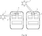
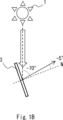
- FIG. 3 is a schematic plan view showing a state in which the display device is irradiated with sunlight directly from the outside of the vehicle or through glass or the like; It is the schematic which shows the incident angle of sunlight with respect to a display device, and a measurement angle.
- 7 is a graph showing an example of a correlation between a ⁇ L * ( ⁇ ) value and a user's sensory evaluation result;
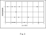
- 5 is a graph showing an example of a correlation between a ⁇ L * (SCI) value and a user's sensory evaluation result;
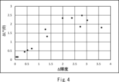
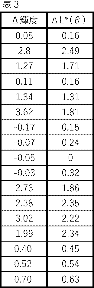
- 4 is a graph showing an example of the correlation between the ⁇ L * ( ⁇ ) value and ⁇ luminance.
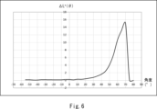
- 4 is a graph showing an example of the angular dependence of ⁇ L * ( ⁇ ) at a light incident angle of ⁇ 70° in the laminate according to this embodiment. 4 is a graph showing another example of the angular dependence of ⁇ L * ( ⁇ ) at a light incident angle of ⁇ 70° in the laminate according to this embodiment.
- the lightness L * defined by the CIE1976L * a * b * display system on the surface of the object to be evaluated before and after applying the oleic acid diluted solution is used as an index, and the durability of the object to be evaluated is evaluated. Fingerprint resistance is evaluated.
- a simultaneous photometric spectrophotometric chromaticity meter is used to measure the lightness L * , and sensory evaluation under a three-wavelength fluorescent lamp is used to evaluate the accuracy of the evaluation method. are doing.
- the incident angle and the measurement angle are not defined, it is not possible to evaluate the fingerprint resistance of the display device under the environment inside the vehicle.
- the results of the sensory evaluation in the actual vehicle differed from each other.
- an oleic acid diluted solution obtained by dissolving oleic acid in ethanol is used to evaluate fingerprint resistance. was sometimes different.
- fingerprint resistance is evaluated by attaching a diluted oleic acid solution using a finger sack, but in this method, a pseudo fingerprint is attached with good reproducibility. Sometimes it was not possible.
- the lightness L * defined by the CIE1976L * a * b * display system is used.
- a photometric spectrophotometer a gonio-colorimeter is used that applies a specific light incidence angle and measurement angle.
- the measurement conditions of the goniophotometer are set to the incident angle:
- the amount of change in the variable angle lightness L * ( ⁇ ) before and after adhesion of the artificial fingerprint liquid when set to ⁇ 70° and the measurement angle to ⁇ 5° is used as an index of anti-fingerprint property. Therefore, in the present invention, it is possible to provide a highly accurate evaluation method of fingerprint resistance (fingerprint conspicuity) that can obtain evaluation results equivalent to sensory evaluation results obtained in an actual vehicle.
- a conventionally known artificial fingerprint liquid can be used for evaluation instead of the oleic acid diluent.
- Some artificial fingerprint liquids take into consideration solid components such as dust and sebum, and by using such artificial fingerprint liquids, it is possible to perform an evaluation that takes actual fingerprints into account more accurately than with dilute oleic acid solutions. can.
- the fingerprint resistance evaluation method of the present invention can be easily applied to a display device having an oil-repellent coating.
- fingerprint resistance can be evaluated in a state where artificial fingerprint liquid is applied using a specific transfer method, so evaluation can be performed under conditions that more closely reflect the actual vehicle environment.
- (Meth)acrylic acid means either one or both of methacrylic acid and acrylic acid.
- the fingerprint resistance evaluation method of the present invention is a method for evaluating the fingerprint resistance of the surface of an object (measurement object), and the artificial fingerprint liquid on the surface of the object is A difference ⁇ L * ( ⁇ ) between a transferred portion and a non-transferred portion obtained by a gonio-colorimeter using the following formula (1) is used.
- formula (1) ⁇ L * ( ⁇ ) L * of artificial fingerprint liquid transferred area ⁇ L * of artificial fingerprint liquid non-transferred area
- the light incident angle is ⁇ 70° with respect to the normal to the surface of the object
- the measurement angle is ⁇ 5° with respect to the normal to the surface of the object.
- the light from the light source 1 such as the sun is irradiated at an incident angle of ⁇ 70° with respect to the normal N of the surface of the display device 3, and ⁇ Fingerprint resistance is evaluated when the user visually observes at an angle of 5° (measurement angle), and an evaluation result reflecting the fingerprint resistance of the display device under a vehicle environment can be obtained.
- the ⁇ L * ( ⁇ ) is preferably 0.5 or less, more preferably 0.45 or less, and 0.1 or less. is more preferred. Also, the smaller ⁇ L * ( ⁇ ) is, the better. It should be noted that ⁇ L * ( ⁇ ) being 0 means that the values measured by the gonio-colorimeter are the same for the area on the surface of the object to which the artificial fingerprint liquid has been transferred and the area to which the artificial fingerprint liquid has not been transferred (the difference is not). Therefore, it can be said that the closer ⁇ L * ( ⁇ ) is to 0, the better. A detailed method for measuring ⁇ L * ( ⁇ ) will be described later.
- a fingerprint is mainly composed of water and a sebum component, and the proportion of the sebum component increases as the water evaporates. Therefore, in many cases, fingerprints can be considered to be sebum.
- sebum-constituting components include fatty acids, glycerolipids, fatty acid esters, wax esters, cholesterol derivatives, and squalene.
- the fatty acid include oleic acid, stearic acid, linolenic acid, palmitic acid, nonanoic acid, adipic acid, tridecanoic acid, myristoleic acid, tetradecanoic acid, and palmitoleic acid.
- Examples of the glycerolipid include monoolein, trimyristin, monocaprylin, triolein, monolaurin, monopalmitin, monostearin, tristearin, tripalmitin, and tricaproin.
- Examples of the fatty acid ester include butyl n-octanoate, benzyl octanoate, isobutyl decanoate, ethyl undecanoate, ethyl stearate, ethyl palmitate, ethyl pentadecanoate, benzyl laurate, amyl n-octanoate, and myristic acid. butyl.
- wax ester examples include dodecyl stearate, decyl decanoate, hexadecyl palmitate, 3-isoamyl-6-methyl-2-heptyl myristate, myricyl palmitate, cecyl palmitate, and myricyl cerotate.
- cholesterol derivatives include cholesterol, 7-dehydrocholesterol, vitamin D, cholic acid, chenodeoxycholic acid, deoxycholic acid, lithocholic acid, progesterone, aldosterone, and cortisol.
- the artificial fingerprint liquid includes inorganic fine particles such as silica fine particles, alumina fine particles, and iron oxide fine particles, as well as keratin fine particles, chitin fine particles, chitosan fine particles, acrylic fine particles, styrene fine particles, divinylbenzene fine particles, polyamide fine particles, It can contain one or more kinds of fine particles selected from organic fine particles such as polyimide-based fine particles, polyurethane-based fine particles, and melamine-based fine particles.
- the artificial fingerprint liquid can also contain Kanto loam (JIS test powder 1) as a particulate matter.
- the average particle size of the particulate matter can be set as appropriate and is not particularly limited, but for example, the average particle size can be 0.05 ⁇ m or more and 100 ⁇ m or less.
- the artificial fingerprint liquid may also contain thickening agents such as carrageenan and gum arabic, and surfactants such as quaternary ammonium salts and alkylbenzenesulfonates.
- the mixing ratio of each component constituting the artificial fingerprint liquid can be appropriately set within the range in which the effects of the present invention can be obtained, and is not particularly limited.
- the artificial fingerprint liquid used in this evaluation method can be diluted with an appropriate organic solvent for use in preparing a thin film (transfer film).
- the organic solvent conventionally known ones can be appropriately used, such as isopropyl alcohol, methyl ethyl ketone, methoxypropanol, and ethanol.
- an artificial fingerprint liquid for example, one having the following composition can be used.
- An artificial fingerprint solution obtained by adding 1.0 g of triolein to 10 g of methoxypropanol as a diluent, and further adding 400 mg of Kanto loam, Class 11 test powder specified in JIS Z8901, and stirring.
- an artificial fingerprint liquid obtained by gently collecting a supernatant portion free from keratin having a large particle size.
- the artificial fingerprint liquid it is preferable to appropriately use one that can reproduce the fingerprint components described above.
- an artificial fingerprint liquid that is solid at a temperature of 20°C and becomes a dispersion at a temperature of 40°C.
- the artificial fingerprint liquid by adding a substance having a melting point higher than room temperature (for example, among the components constituting the sebum described above) to the artificial fingerprint liquid described above, the artificial fingerprint becomes solid at a temperature of 20 ° C. and a dispersed system at a temperature of 40 ° C. liquid can be produced.
- An artificial fingerprint solution with this property adheres more easily to the coating surface than the conventional diluted oleic acid solution that uses oleic acid alone, and can be used for evaluations that take into account actual fingerprint adhesion. Excellent for
- the squalene content in the artificial fingerprint liquid is preferably 10 to 15% by mass from the viewpoint of performing the evaluation appropriately.
- the refractive index of the sebum should lie between the minimum and maximum refractive indices of the components contained in the sebum.
- the substance with the lowest refractive index is n-butyl octanoate, which has a refractive index of 1.42.
- the substance with the highest refractive index is benzyl octanoate, which has a refractive index of 1.49. Therefore, the index of refraction of fingerprints is believed to be in the range of 1.42 to 1.49.
- a conventionally known method can be applied to the transfer method of the artificial fingerprint liquid, but it is preferable to use the following method. That is, the artificial fingerprint liquid is applied to the transfer substrate by a spin coating method to prepare a transfer foil having a haze value of 7 ⁇ 2%, and after pressing a pseudo finger against the transfer foil with a load of 60 N, the It is preferable to use a method of pressing a pseudo finger against the surface of the object with a load of 60 N for 2 seconds. In this method, the artificial fingerprint liquid is dripped onto the rotating transfer base material by spin coating, and a uniform thin film can be formed by centrifugal force, so it is possible to transfer the artificial fingerprint liquid with good reproducibility. can.
- the transfer base material conventionally known ones can be appropriately used, and for example, a polycarbonate plate can be used.
- artificial finger conventionally known ones can be used as appropriate, and for example, natural rubber (rubber hardness: Shore E60, Shore E70 according to JIS K 6253 standard) can be used. Further, as described above, it is preferable to use an artificial fingerprint liquid that is solid at a temperature of 20.degree. C. and becomes a dispersion system at a temperature of 40.degree.
- the luminance difference ⁇ which is obtained by the following formula (2), measured by a luminance meter between the area where the artificial fingerprint liquid is transferred and the area where the artificial fingerprint liquid is not transferred on the surface of the display device.
- ⁇ Luminance Luminance of transfer area of artificial fingerprint liquid - Luminance of non-transfer area of artificial fingerprint liquid
- the ⁇ luminance is preferably 0.5 [cd/m 2 ] or less from the viewpoint of obtaining excellent anti-fingerprint property.
- ⁇ luminance and ⁇ L * ( ⁇ ) There is a certain correlation between ⁇ luminance and ⁇ L * ( ⁇ ), and by setting both ⁇ luminance and ⁇ L * ( ⁇ ) to favorable values, it is possible to impart superior anti-fingerprint properties. .
- a detailed method for measuring ⁇ luminance will be described later.
- the amount of squalene attached for example, assuming that a fingerprint is attached
- the amount of squalene adhered is less than 40 ⁇ g, fingerprints are less conspicuous and the anti-fingerprint property is excellent. A detailed method for measuring the amount of squalene attached will be described later.
- the laminate of the present invention (hereinafter sometimes referred to as the laminate) has a surface in which the measured value difference ⁇ L * ( ⁇ ) in the present evaluation method described above is 0.5 or less, and therefore has excellent fingerprint resistance. , fingerprints attached to the surface can be made inconspicuous.
- the method of transferring the artificial fingerprint liquid used for the evaluation it is preferable to use the transfer method by the spin coating method described above.
- the laminate can have a substrate, a predetermined layer arranged on the substrate, and an outermost layer arranged on the predetermined layer.
- the predetermined layer may include a first predetermined layer on the substrate side and a second predetermined layer on the outermost layer side.
- the substrate and the first predetermined layer between the first predetermined layer and the second predetermined layer, between the outermost layer and the second predetermined layer, etc., other It may have a layer (middle layer).
- intermediate layers include desired functional layers, pressure-sensitive adhesive layers, ultraviolet absorbing layers, infrared absorbing layers, antireflection layers, soft (impact-resistant) layers, hard coat layers, conductive layers, antistatic layers, heat insulating layers, and reflective layers. Layers, primer layers, etc. can be used.
- the outermost layer is placed under the condition that it is touched by human hands during use.
- an oil-repellent coating layer or a lipophilic coating layer which will be described later, can be provided.
- This laminate may be used for the operation surface of a touch panel, or may be used for the display surface of a display panel or a protective member such as a cover panel covering it. However, the use of the present laminate is not limited to these.
- the refractive index of the first predetermined layer is preferably more than 1.49, more preferably 1.60 or more, and 2.00 or less, from the viewpoint of imparting excellent fingerprint resistance. It is preferably 1.80 or less, more preferably 1.80 or less.
- the refractive index of the second predetermined layer is preferably 1.43 or more, more preferably 1.45 or more, and 1.49 or less, from the viewpoint of imparting excellent fingerprint resistance. It is preferably 1.47 or less, more preferably 1.47 or less. Since the refractive index of fingerprints is considered to be 1.42 to 1.49 as described above, it is more preferable that the refractive index of the second predetermined layer is close to the average value of 1.46. .
- the second predetermined layer has a refractive index of 1.43 to 1.49, the interface reflectance between the fingerprint and the surface of the laminate is small, and the difference between the fingerprint adhered portion and other portions is reduced, Fingerprints are less noticeable.
- the refractive index of the base material can be appropriately set, and for example, a base material having a refractive index of 1.50 can be used.
- the refractive index of each layer can be measured using an ellipsometer or the like.
- the material constituting the base material is not particularly limited, and conventionally known materials can be used as appropriate.
- the substrate may be a transparent resin film made of TAC (triacetyl cellulose), PMMA (polymethyl methacrylate), PC (polycarbonate), PET (polyethylene terephthalate), or the like, or a laminated film (laminate) thereof, that is, a resin substrate. It can be wood.
- a conventionally known base material made of glass (glass base material) may be used as the base material.
- Materials constituting the first predetermined layer, the second predetermined layer, and the outermost layer are not particularly limited.
- ZrO 2 , Al 2 O 3 , SiO 2 ), etc. may each be composed of a thin film obtained by, for example, vacuum deposition, sputtering or wet coating. These layers can be imparted with different characteristics depending on the type of additives and resins they contain.
- the angular dependence of ⁇ L * ( ⁇ ) at a light incident angle of ⁇ 70° has a negative peak in the specular reflection region and a positive peak at angles other than the specular reflection region.
- the squalene loading on said surface is less than 40 ⁇ g.
- the angular dependence of ⁇ L * ( ⁇ ) at a light incident angle of ⁇ 70° has a negative (minus) peak in the specular reflection region (+70 ⁇ 10°).
- the graph has positive (plus) peaks at angles other than the specular reflection region. Note that having a negative peak in the specular reflection region means that the angle (°) of the apex of the negative peak is within the range of the specular reflection region (70° in FIG. 5). interpretable. Further, having a positive peak at an angle other than the specular reflection region means that the angle (°) at the apex of the positive peak is within the range other than the specular reflection region (55° in FIG. 5). can also be interpreted to mean
- the angle dependence of ⁇ L * ( ⁇ ) at a light incident angle of ⁇ 70 ° has a lipophilic coating on the surface (outermost layer) that does not have a positive peak at angles other than the specular reflection region is also preferred.
- the lipophilic coating can have a positive peak only in the specular reflection region in the angular dependence of ⁇ L * ( ⁇ ) at a light incident angle of ⁇ 70°.
- FIG. 6 shows a graph showing an example of the angular dependence of ⁇ L * ( ⁇ ) at a light incident angle of ⁇ 70° in the laminate having the oleophilic coating on the surface according to this embodiment. In the graph shown in FIG.
- the angular dependence of ⁇ L * ( ⁇ ) at the light incident angle of ⁇ 70° does not have a positive peak at angles other than the specular reflection region (+70 ⁇ 10°), and only in the specular reflection region. It has a positive peak.
- the angle (°) of the apex of the positive peak is within the specular reflection region (70° in FIG. 6).
- the angular dependence of the displacement angle ⁇ L * ( ⁇ ) described above is not limited to the light incident angle of ⁇ 70°, and the same behavior is observed even at the light incident angle of ⁇ 30°, for example.
- the distance from the surface of the outermost layer disposed on the second predetermined layer to the second predetermined layer is preferably 60 nm or less. If the distance is 60 nm or less, optical interference due to the difference between the refractive index of the lipophilic outermost layer and the refractive index of fingerprints (sebum) attached to the surface can be suppressed, and fingerprints can be made less conspicuous. .
- the thickness of the outermost layer is preferably 60 nm or less.
- the total thickness of the outermost layer and the other layer is preferably 60 nm or less.
- the ⁇ luminance on the surface calculated from the above formula (2) is 0.5 [cd/m 2 ] or less.
- each numerical value described above is based on the simulation result by the inventors.
- the simulation is performed under various conditions in which the refractive index (including the refractive index of air) and thickness of each member of the laminate are appropriately changed, and the desired numerical range is determined based on the results.
- the refractive index including the refractive index of air
- the desired numerical range is determined based on the results.
- the thickness of a fingerprint is usually 10 to several hundred nm in actual measurements, 50 nm was used as a representative value in the simulation.
- RA is the intensity reflectance of the surface of the laminate
- RB is the intensity reflectance of the fingerprint adhered to the surface of the laminate. Since Y is proportional to lightness L * , when ⁇ Y is small, ⁇ L * ( ⁇ ) is also small.
- Equation I the intensity reflectance Rm is given by Equation I below.
- ⁇ a refractive index of air
- ⁇ s refractive index of base material
- m component of characteristic matrix [M].
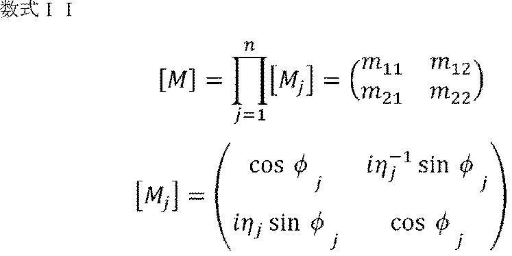
- the characteristic matrix [M] is represented by Equation II below.
- n number of layers laminated on the substrate
- j order from the outermost layer (uppermost layer) of each layer laminated on the substrate
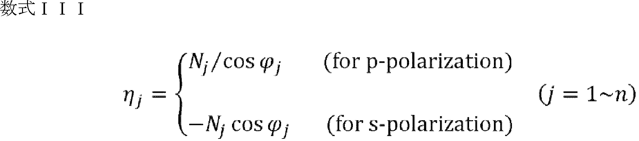
- ⁇ optical admittance
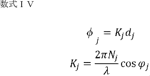
- ⁇ optical path length.
- N the refractive index of each layer
- ⁇ the angle of incidence on each layer.
- d is the thickness of each layer
- ⁇ is the wavelength of light.
- the distance from the surface of the laminate to the second predetermined layer, the refractive index of each layer, and the like can be measured non-destructively using an ellipsometer.
- the laminate may be cut, and the cut surface may be observed or analyzed after ion milling or FIB (Focused Ion Beam) processing.
- FIB Fluorused Ion Beam
- XPS X-ray photoelectron spectroscopy
- the number of layers and film thickness may be confirmed with an electron microscope. It is also possible to confirm the structure with higher accuracy by comparing the results of measurement by an ellipsometer with other observations or analysis results.
- the laminate manufacturing method of the present invention (hereinafter sometimes referred to as the present manufacturing method), the laminate is manufactured so that the above-described ⁇ L * ( ⁇ ) is 0.5 or less on the surface of the laminate.
- the laminate obtained by this production method can have excellent anti-fingerprint properties.
- the surface of the laminate can be surface-treated so that ⁇ L * ( ⁇ ) is 0.5 or less.
- the surface treatment method is not particularly limited as long as the effects of the present invention can be obtained, and conventionally known methods can be used.
- AG (Anti-Glare) coating can be applied to the substrate surface.
- AG coating can diffuse reflected light and suppress reflection and glare by providing very fine irregularities on the surface of the base material.
- the laminate of the present invention can be produced, for example, by the following procedure. First, on a base material such as a resin base material or a glass base material, a coating liquid containing an active energy ray-curable resin is applied using a bar coater or the like, and if necessary, heated (for example, 80 ° C. for 90 seconds) and dry. After that, active energy ray curing is performed in an inert gas (for example, nitrogen gas) atmosphere to form a hard coat film having a predetermined thickness (for example, 5 ⁇ m).
- an inert gas for example, nitrogen gas
- An active energy ray-curable resin contains a polymerizable compound that can form a cured product by causing a curing reaction when irradiated with an active energy ray.
- a polymerizable compound a monofunctional monomer, a polyfunctional monomer, an oligomer or polymer having a vinyl group or a (meth)acryloyl group can be used.
- monofunctional monomers include methyl (meth)acrylate, ethyl (meth)acrylate, isopropyl (meth)acrylate, n-butyl (meth)acrylate, t-butyl (meth)acrylate, ( meth)isobutyl acrylate, n-hexyl (meth)acrylate, 2-ethylhexyl (meth)acrylate, isodecyl (meth)acrylate, lauryl (meth)acrylate, stearyl (meth)acrylate, (meth)acrylic acid Cetyl, isobornyl (meth)acrylate, cyclohexyl (meth)acrylate, tricyclodecyl (meth)acrylate, benzyl (meth)acrylate, tetrahydrofurfuryl (meth)acrylate, dicyclopentenyloxy (meth)acrylate Ethyl, dicyclopentanyl (meth)acrylate, pent
- ( meth)acrylates styrene, ⁇ -methylstyrene, p-methoxystyrene, m-methoxystyrene, di-t-butyl fumarate, di-n-butyl fumarate, diethyl fumarate, mono(di)methyl itaconate, Mono(di)ethyl itaconate, N-isopropylacrylamide, N-vinyl-2-pyrrolidone and the like can be used.
- polyfunctional monomers include esters of polyhydric alcohols and (meth)acrylic acid, and polyfunctional polymerizable compounds containing two or more (meth)acryloyl groups such as urethane-modified acrylates.
- polyhydric alcohols include ethylene glycol, diethylene glycol, triethylene glycol, tetraethylene glycol, polyethylene glycol, propylene glycol, dipropylene glycol, tripropylene glycol, tetrapropylene glycol, polypropylene glycol, propanediol, butanediol, pentanediol, Dihydric alcohols such as hexanediol, neopentyl glycol, 2-ethyl-1,3-hexanediol, 2,2′-thiodiethanol, 1,4-cyclohexanedimethanol; trimethylolpropane, glycerol, pentaerythritol, di Trihydric or higher alcohols
- a urethane-modified acrylate can be obtained by a urethanization reaction between an organic isocyanate having multiple isocyanate groups in one molecule and a (meth)acrylic acid derivative having a hydroxyl group.
- organic isocyanates having a plurality of isocyanate groups in one molecule include hexamethylene diisocyanate, isophorone diisocyanate, tolylene diisocyanate, naphthalene diisocyanate, diphenylmethane diisocyanate, xylylene diisocyanate, dicyclohexylmethane diisocyanate, and the like. and organic isocyanates having three isocyanate groups in one molecule obtained by isocyanurate-, adduct-, or biuret-modified organic isocyanates.
- Oligomers having a vinyl group or (meth)acryloyl group include polyester oligomers, epoxy oligomers, urethane oligomers, polyether oligomers, alkyd oligomers, polybutadiene oligomers, polythiolpolyene oligomers and spiroacetal oligomers, and polyfunctional polyhydric alcohols. Oligomers obtained by adding a vinyl group or a (meth)acryloyl group to an oligomer composed of (meth)acrylic acid ester are exemplified. Polymers having a vinyl group or a (meth)acryloyl group include oligomer polymer types having the vinyl group or the (meth)acryloyl group.
- the coating liquid may contain a diluent solvent, beads, fillers, photodegradable or thermally decomposable polymerization initiators, metal oxides, surfactants, ultraviolet absorbers, infrared absorbers, and antioxidants.
- Additives such as agents, photosensitizers, light stabilizers, and silane coupling agents can be incorporated.
- diluent solvents include toluene, xylene, ethyl acetate, propyl acetate, butyl acetate, methyl cellosolve, ethyl cellosolve, ethyl cellosolve acetate, methyl alcohol, ethyl alcohol, isopropyl alcohol, butyl alcohol, acetone, methyl ethyl ketone, methyl isobutyl ketone, cyclohexanone, hexane, heptane, octane, decane, dodecane, propylene glycol monomethyl ether, 3-methoxybutanol and the like.
- polymerization initiators examples include benzophenones, acetophenones, ⁇ -amyloxime esters, Michler benzoyl benzoate, tetramethylthurum monosulfide, and thioxanthones.
- 1-hydroxycyclohexylphenyl ketone 2-hydroxy-2-methyl-1-phenylpropan-1-one, 2-methyl-1-[4-(methylthio)phenyl]-2-morphelinopropan-1-one, 1-[4-(2- hydroxyethoxy)phenyl]-2-hydroxy-2-methyl-1-propan-1-one, benzoin, 2,2-dimethoxy-1,2-diphenylethan-1-one, benzophenone, [4-(methylphenylthio ) phenyl]phenylmethanone, 4-hydroxybenzophenone, 4-phenylbenzophenone, 3,3′,4,4′-tetra(t-butylperoxycarbonyl)benzophenone, 2-chlorothioxanthone, 2,4-diethylthioxanthone, Examples include ⁇ -amyloxime ester, Michler benzoyl benzoate, tetramethylturam monosulfide and the like.
- metal oxides examples include silica, hollow silica, aluminum oxide (alumina), titanium oxide, antimony oxide, zinc oxide, tin oxide, and zirconium oxide.
- a surfactant it is used for the purpose of compatibilization when various raw materials are blended and for the purpose of improving the smoothness of the film, and is not particularly limited, but acrylic copolymers (ionic, nonionic) , methacrylic copolymers, solvent-based paint leveling agents, polysiloxane compounds, and the like.
- photosensitizer known compounds for the above-mentioned polymerization initiators are used, such as tributylamine, triethylamine, polyethyleneimine, poly-n-butylphosphine, p-dimethylaminobenzoic acid ethyl ester, p-dimethyl Tertiary amines such as aminobenzoic acid isoamyl ester and the like are included.
- the mixing ratio of these various components can be appropriately set within the range in which the effects of the present invention can be obtained, and is not particularly limited.
- Various properties such as optical properties, coating film properties and durability of the produced laminate can be adjusted by properly blending these various components.
- conventionally known conditions can be appropriately used for the active energy ray and its irradiation amount, and for example, a metal halide lamp can be used.
- each layer can be appropriately selected according to the desired refractive index and reflectance, and the number of layers, thickness, and the like can be appropriately set.
- each of the first predetermined layer and the second predetermined layer may be formed one layer at a time, or may be a laminate in which a plurality of layers are alternately laminated.
- the thickness of the first predetermined layer and the thickness of the second predetermined layer can be, for example, 1 nm or more and 200 nm or less.
- each layer may be formed by a sputtering method, a wet coating method, or the like.
- the first predetermined layer includes niobium pentoxide (Nb 2 O 5 ), titanium oxide (TiO 2 ), tungsten oxide (WO 3 ), cerium oxide (CeO 2 ), tantalum pentoxide (Ta 2 O 5 ), zinc oxide ( ZnO), indium oxide ( In2O3 ), tin oxide ( SnO2 ), hafnium oxide (HfO2), indium tin oxide ( ITO ), zirconium oxide ( ZrO2 ), aluminum oxide ( Al2O3 ), oxide Antimony (Sb 2 O 3 ), neodymium oxide (Nd 2 O 3 ), zinc sulfide (ZnS) and the like can be used.
- the first predetermined layer contains phenol resin, urea resin, diallyl phthalate resin, melamine resin, guanamine resin, unsaturated polyester resin, polyurethane resin, epoxy resin, aminoalkyd resin, melamine-urea cocondensation resin, silicon resin, poly A thermosetting resin such as a siloxane resin may also be used.
- the first predetermined layer may contain an inorganic material such as silica, alumina, zirconia, or titania, or an organic material such as acrylic resin.
- the second predetermined layer preferably contains an oxide of Si, and is preferably a layer containing SiO 2 (oxide of Si) or the like as a main component.
- the main component means the component with the highest content among the components contained in the target (here, the second predetermined layer).
- the second predetermined layer can contain elements such as Na for improving durability, Zr, Al, and N for improving hardness, and Zr and Al for improving alkali resistance. .
- the second predetermined layer includes, for example, magnesium fluoride (MgF 2 ), sodium fluoride (NaF), cryolite (Na 3 AlF 6 ), thiolite (Na 5 Al 3 F 14 ), lithium fluoride (LiF), Also contains aluminum fluoride (AlF 3 ), calcium fluoride (CaF 2 ), styrontium fluoride (SrF 2 ), zirconium fluoride (ZrF 4 ), barium fluoride (BaF 2 ), yttrium fluoride (YF 3 ), etc. can.
- MgF 2 magnesium fluoride
- NaF sodium fluoride
- cryolite Na 3 AlF 6
- thiolite Na 5 Al 3 F 14
- lithium fluoride LiF
- AlF 3 aluminum fluoride
- CaF 2 calcium fluoride
- SrF 2 styrontium fluoride
- ZrF 4 zirconium fluoride
- barium fluoride BaF 2
- the first predetermined layer raw materials: ZrO 2 /Al 2 O 3 are used, and an AR coating film (for example, film thickness: 150 nm) having a refractive index of 1.70 is formed by a vacuum deposition method. can be formed.
- an AR coating film e.g., film thickness: 90 nm
- a refractive index of 1.46 is formed on the first predetermined layer by vacuum deposition using SiO 2 as a raw material. can be formed.
- a silane coupling agent for example, perfluoropolyether-based silane coupling agent
- a high temperature and high humidity for example, a temperature of 50 ° C. and a relative humidity of 90%
- AF Anti-Fingerprint
- the outermost layer is formed using a fluorine compound having at least one functional group selected from the group consisting of a fluoroalkyl group, a fluorooxyalkyl group, a fluoroalkenyl group, a fluoroalkanediyl group and a fluorooxyalkanediyl group.
- An oleophobic coating layer can be used.
- Some of these functional groups may have --H groups remaining, or all of the H groups may be replaced with fluorine (--F) groups.
- the structure may have branches, and a plurality of these may be linked to form a dimer, trimer, oligomer, or polymer structure.
- the fluorine compound includes a silyl ether group, an alkoxysilyl group, a silanol group obtained by hydrolyzing an alkoxysilyl group, a reactive group such as a carboxyl group, a hydroxyl group, an epoxy group, a vinyl group, an allyl group, an acryloyl group, and a methacryloyl group. You may have a group.
- R f1 -R 2 -D 1 General formula (A)
- R f1 is a moiety containing a fluoroalkyl group, fluorooxyalkyl group, fluoroalkenyl group, fluoroalkanediyl group, and fluorooxyalkanediyl group
- R2 is an alkanediyl group, an alkanetriyl group, and ester structure, urethane structure, ether structure, and triazine structure
- D1 indicates a reactive site
- Examples of the compound represented by formula (A) include the following. 2,2,2-trifluoroethyl acrylate, 2,2,3,3,3-pentafluoropropyl acrylate, 2-perfluorobutylethyl acrylate, 3-perfluorobutyl-2-hydroxypropyl acrylate, 2-perfluorobutyl fluorohexyl ethyl acrylate, 3-perfluorohexyl-2-hydroxypropyl acrylate, 2-perfluorooctyl ethyl acrylate, 3-perfluorooctyl-2-hydroxypropyl acrylate, 2-perfluorodecyl ethyl acrylate, 2-perfluoro- 3-methylbutyl ethyl acrylate, 3-perfluoro-3-methoxybutyl-2-hydroxypropyl acrylate, 2-perfluoro-5-methylhexyl ethyl acrylate, 3-perfluoro-5-methylhe
- a hydrolyzable organosilane compound eg, one containing a hindered ester group
- a lipophilic coating layer using a hydrolytic condensate thereof can be used as the outermost layer.
- the organosilane compound can contain a hindered ester group that is excellent in lipophilicity and heat resistance, and a hydrolyzable silyl group (eg, an alkoxysilyl group) or a hydroxyl group-containing silyl group.
- a hydrolyzable silyl group eg, an alkoxysilyl group
- a hydroxyl group-containing silyl group e.g, an alkoxysilyl group
- the display device of the present invention (hereinafter sometimes referred to as the present display device) is not particularly limited as long as it includes the present laminate, and conventionally known devices can be appropriately applied. Since the present display device having the present laminate is excellent in fingerprint resistance, it can be suitably used for various electronic devices such as a display device having a touch panel, a display panel, or the like.
- Examples 1 to 15 and Examples 31 to 33 described later are examples for evaluating the fingerprint resistance evaluation method of the present invention
- Examples 16 to 30 are examples for evaluating conventional evaluation methods. For example.
- a natural rubber pad (natural rubber, rubber hardness: Shore E70) having a diameter of 20 mm and a thickness of 2 mm was pressed against the transfer foil of the artificial fingerprint liquid with a load of 60 N for 2 seconds, and then the natural rubber pad onto which the artificial fingerprint liquid had been transferred. was pressed against the sample with a load of 60 N for 2 seconds to transfer the artificial fingerprint liquid to the sample, thereby preparing a measurement sample. Since the purpose of this example is to verify the correlation between ⁇ L * ( ⁇ ) and the results of sensory evaluation, the detailed description of each sample is omitted.
- Example 1 A first layer having a refractive index of 2.33 and a second layer having a refractive index of 1.46 were formed on a glass substrate whose surface was coated with AG, and the surface was coated with an oil-repellent coating (reflectance: 0.00). 3%).
- Example 4 A resin plate is used as a base material with an AG coating on the surface, and a lipophilic coating is applied to the surface of the laminate (reflectance: 4.5%).
- Example 5 A resin plate having an AG-coated surface on which a first layer with a refractive index of 2.33 and a second layer with a refractive index of 1.46 are formed (reflectance: 0.4%).
- an evaluation environment was constructed that reproduced the actual vehicle environment of the incident angle of sunlight and the positional relationship between the display device and the user, and based on the following sensory evaluation criteria.
- sensory evaluation by humans Specifically, artificial sunlight was used as sunlight, the illuminance was 30000 to 60000 lux, the incident angle of the artificial sunlight was ⁇ 70°, and the observation angle by the user was ⁇ 5°.
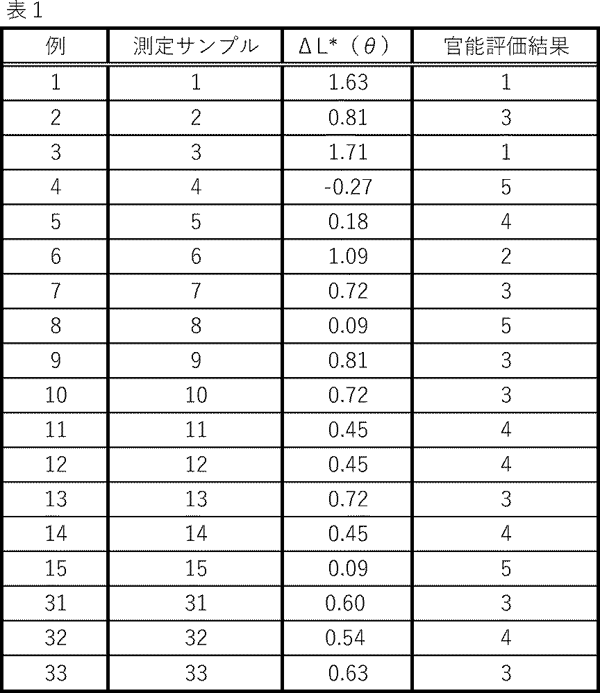
- the ⁇ L * ( ⁇ ) value was measured and sensory evaluation was performed by the user on 18 measurement samples 1 to 15 and 31 to 33, and the correlation between the ⁇ L * ( ⁇ ) value and the sensory evaluation result was performed. confirmed the relationship.
- the results of each measurement sample are shown in Table 1 below, and a graph showing the correlation of each measurement sample is shown in FIG.
- the optical index ⁇ L * (SCI), which has been conventionally used as an evaluation index for anti-fingerprint property and indicates the angle-integrated reflection intensity of all angles by an integrating sphere, properly evaluates anti-fingerprint property. found to be difficult to do.
- oleic acid may remain on the gauze, droplets may repel, and so on, and oleic acid may not be transferred to the sample with good reproducibility.
- ⁇ luminance measurement Using a luminance meter (trade name: SR-UL1R, manufactured by Topcon Technohouse Co., Ltd.), the luminance of the part where the artificial fingerprint liquid was transferred and the part where the artificial fingerprint liquid was not transferred was measured for the measurement sample prepared by the above procedure.
- ⁇ luminance [cd/m 2 ] was calculated based on the following formula (2).
- ⁇ Luminance Brightness of area where artificial fingerprint liquid has been transferred - brightness of area where artificial fingerprint liquid has not been transferred
- the light incident angle is 85° above the normal line of the surface of the measurement sample, and the measurement angle is above the normal line of the surface of the measurement sample.
- the artificial fingerprint liquid (squalene content: 13% by mass) was transferred to the surface of the measurement sample.
- the wool was impregnated with normal hexane, the surface was scrubbed and washed with normal hexane, and the washings were collected in a 40 mL container. Then, after putting the used quartz wool into the container, the container was sealed and subjected to ultrasonic extraction for 5 minutes.
- the calibration curve used to measure the amount of squalene was prepared from the area value obtained from the adjusted concentration and the measurement result by applying a standard solution that was diluted stepwise with normal hexane to a measuring device.
- GC - Measuring device gas chromatography
- MS Mass spectrometer
- JEOL JMS-Q1500GC (trade name) ⁇ GC conditions
- Analytical column Agilent Technologies (trade name) 5% phenyl-95% methylsiloxane
- a display device with an oil-repellent coating specifically, the angular dependence of ⁇ L * ( ⁇ ) at a light incident angle of ⁇ 70 ° has a negative peak in the regular reflection region (70 ⁇ 10 °). and have a positive peak at angles other than the specular reflection region.
- the angle dependence of ⁇ L * ( ⁇ ) was obtained by the same method as the measurement method for the diffuse reflection anti-fingerprint property ⁇ L * ( ⁇ ) described above, with a measurement angle of ⁇ 60° to +85°, and ⁇ L * for each angle. It was obtained by calculating ( ⁇ ). Table 4 below shows the relationship between the amount of squalene adhered after transfer of the artificial fingerprint liquid (assuming that a fingerprint adheres) and ⁇ L * ( ⁇ ) in the measurement sample.
- ⁇ L * ( ⁇ ) is 0.5 or less, indicating excellent anti-fingerprint properties.
- the angle dependence of ⁇ L * ( ⁇ ) at a light incident angle of ⁇ 70° does not have a positive peak at angles other than the specular reflection region.
- ⁇ L * ( ⁇ ) does not depend on the amount of squalene attached.
- the fingerprint resistance evaluation method of the present invention is an excellent evaluation method that can also be applied to in-vehicle display devices. It should be noted that the present invention is not limited to the above embodiments, and can be modified as appropriate without departing from the scope of the invention.
Landscapes
- Physics & Mathematics (AREA)
- Chemical & Material Sciences (AREA)
- General Physics & Mathematics (AREA)
- Immunology (AREA)
- Pathology (AREA)
- Health & Medical Sciences (AREA)
- Life Sciences & Earth Sciences (AREA)
- Analytical Chemistry (AREA)
- Biochemistry (AREA)
- General Health & Medical Sciences (AREA)
- Spectroscopy & Molecular Physics (AREA)
- Engineering & Computer Science (AREA)
- Mathematical Physics (AREA)
- Theoretical Computer Science (AREA)
- Optics & Photonics (AREA)
- Chemical Kinetics & Catalysis (AREA)
- Measurement Of The Respiration, Hearing Ability, Form, And Blood Characteristics Of Living Organisms (AREA)
- Laminated Bodies (AREA)
Abstract
Description
[1]対象物表面の耐指紋性を評価する方法であって、前記対象物表面における人工指紋液が転写された部位と転写されていない部位との変角測色計による下記式(1)より求められる測定値差ΔL*(θ)を用いることを特徴とする耐指紋性の評価方法:
式(1)
ΔL*(θ)=人工指紋液転写部のL*-人工指紋液非転写部のL*
但し、光入射角度は、前記対象物表面の法線に対して-70°とし、測定角度は、前記対象物表面の法線に対して-5°とする。
[2]前記対象物表面の耐指紋性を評価する際に、さらに、前記対象物表面における人工指紋液が転写された部位と転写されていない部位との輝度計による下記式(2)により求められる測定値差Δ輝度を用いる、[1]に記載の評価方法:
式(2)
Δ輝度=人工指紋液転写部の輝度-人工指紋液非転写部の輝度
[3]前記人工指紋液の転写方法が、転写用基材に前記人工指紋液をスピンコーティング法により付着させ、ヘイズ値が7±2%である転写箔を作製し、前記転写箔に疑似指を荷重60Nで押し当てた後、前記疑似指を前記対象物表面に荷重60Nで2秒間押し当てる方法である、[1]または[2]に記載の評価方法。
[4]前記対象物表面の耐指紋性を評価する際に、さらに、前記対象物表面のスクアレン付着量を用いる、[1]~[3]のいずれかに記載の評価方法。
[5]人工指紋液が転写された部位と転写されていない部位との変角測色計による下記式(1)より求められる測定値差ΔL*(θ)が0.5以下である表面を有することを特徴とする積層体:
式(1)
ΔL*(θ)=人工指紋液転写部のL*-人工指紋液非転写部のL*
但し、光入射角度は、測定対象物表面の法線に対して-70°とし、測定角度は、前記測定対象物表面の法線に対して-5°とする。
[6]基材と、前記基材上に配される所定層と、前記所定層上に配される最表層とを有し、
前記所定層は、前記基材側の第1所定層と、前記最表層側の第2所定層とを含み、
前記第1所定層の屈折率は、2.00以下である、[5]に記載の積層体。
[7]基材と、前記基材上に配される所定層と、前記所定層上に配される最表層とを有し、
前記所定層は、前記基材側の第1所定層と、前記最表層側の第2所定層とを含み、
前記第2所定層の屈折率は、1.43以上1.49以下である、[5]または[6]に記載の積層体。
[8]前記積層体の表面において、前記光入射角度-70°におけるΔL*(θ)の角度依存性が、正反射領域において負のピークを持ち、前記正反射領域以外の角度において正のピークを持ち、
前記積層体の表面におけるスクアレン付着量が、40μg未満である、[5]~[7]のいずれかに記載の積層体。
[9]前記積層体の表面において、前記光入射角度-70°におけるΔL*(θ)の角度依存性が、正反射領域以外の角度において正のピークを持たない、[5]~[7]のいずれかに記載の積層体。
[10]最表層は、第2所定層上に配され、前記最表層の表面から前記第2所定層までの距離が、60nm以下である、[9]に記載の積層体。
[11]前記表面における人工指紋液が転写された部位と転写されていない部位との輝度計による下記式(2)により求められる測定値差Δ輝度が、0.5[cd/m2]以下である、[5]~[10]のいずれかに記載の積層体:
式(2)
Δ輝度=人工指紋液転写部の輝度-人工指紋液非転写部の輝度
[12]前記人工指紋液の転写方法が、転写用基材に前記人工指紋液をスピンコーティング法により付着させ、ヘイズ値が7±2%である転写箔を作製し、前記転写箔に疑似指を荷重60Nで押し当てた後、前記疑似指を前記積層体の表面に荷重60Nで2秒間押し当てる方法である、[5]~[11]のいずれかに記載の積層体。
[13][5]~[12]のいずれかに記載の積層体を有することを特徴とする表示装置。
[14]積層体の表面において、人工指紋液が転写された部位と転写されていない部位との変角測色計による下記式(1)より求められる測定値差ΔL*(θ)が0.5以下となるように、前記積層体を製造することを特徴とする積層体の製造方法:
式(1)
ΔL*(θ)=人工指紋液転写部のL*-人工指紋液非転写部のL*
但し、光入射角度は、測定対象物表面の法線に対して-70°とし、測定角度は、前記測定対象物表面の法線に対して-5°とする。
また、特許文献1に記載の評価方法では、耐指紋性の評価にオレイン酸をエタノールに溶解させたオレイン酸希釈液を用いているが、当該希釈液では表示装置への付着状態が実際の指紋と異なる場合があった。特に撥油性コーティングを備えた表示装置については、オレイン酸希釈液の液滴ハジキの影響で、耐指紋性を正確に評価することが困難な場合があった。
さらに、特許文献1に記載の評価方法では、指サックを使用してオレイン酸希釈液を付着させて、耐指紋性の評価を行っているが、当該方法では、再現性良く疑似指紋を付着させることができない場合があった。
また、本発明では、オレイン酸希釈液ではなく、例えば、従来公知の人工指紋液を評価に用いることができる。人工指紋液では、ゴミや皮脂等の固形成分を考慮したものもあり、こういった人工指紋液を用いることで、オレイン酸希釈液よりも実際の指紋付着を考慮した評価を正確に行うことができる。また、こういった固形成分を含む人工指紋液を用いることで、撥油性コーティングを備えた表示装置にも容易に本発明の耐指紋性の評価方法を適用できる。
さらに、本発明では、特定の転写方法を用いて、人工指紋液を付着させた状態で耐指紋性を評価できるため、より実際の車両環境を反映させた条件で評価を行うことができる。
本発明の耐指紋性の評価方法(以降、本評価方法と称することがある)は、対象物(測定対象物)表面の耐指紋性を評価する方法であり、対象物表面における人工指紋液が転写された部位と転写されていない部位との変角測色計による下記式(1)より求められる測定値差ΔL*(θ)を用いるものである。
式(1)
ΔL*(θ)=人工指紋液転写部のL*-人工指紋液非転写部のL*
但し、光入射角度は、前記対象物表面の法線に対して-70°とし、測定角度は、前記対象物表面の法線に対して-5°とする。
前記脂肪酸としては、例えば、オレイン酸、ステアリン酸、リノレン酸、パルミチン酸、ノナン酸、アジピン酸、トリデカン酸、ミリストレイン酸、テトラデカン酸、パルミトレイン酸が挙げられる。
また、前記グリセロ脂質としては、例えば、モノオレイン、トリミリスチン、モノカプリリン、トリオレイン、モノラウリン、モノパルミチン、モノステアリン、トリステアリン、トリパルミチン、トリカプロインが挙げられる。
前記脂肪酸エステルとしては、例えば、n-オクタン酸ブチル、オクタン酸ベンジル、デカン酸イソブチル、ウンデカン酸エチル、ステアリン酸エチル、パルミチン酸エチル、ペンタデカン酸エチル、ラウリン酸ベンジル、n-オクタン酸アミル、ミリスチン酸ブチルが挙げられる。
前記ワックスエステルとしては、例えば、ステアリン酸ドデシル、デカン酸デシル、パルミチン酸ヘキサデシル、ミリスチン酸3-イソアミル-6-メチル-2-ヘプチル、パルミチン酸ミリシル、パルミチン酸セシル、セロチン酸ミリシルが挙げられる。
前記コレステロール誘導体としては、例えば、コレステロール、7-デヒドロコレステロール、ビタミンD、コール酸、ケノデオキシコール酸、デオキシコール酸、リトコール酸、プロゲステロン、アルドステロン、コルチゾールが挙げられる。
さらに、人工指紋液には、シリカ微粒子、アルミナ微粒子、酸化鉄微粒子などの無機微粒子、ならびに、ケラチン微粒子、キチン微粒子、キトサン微粒子、アクリル系微粒子、スチレン系微粒子、ジビニルベンゼン系微粒子、ポリアミド系微粒子、ポリイミド系微粒子、ポリウレタン系微粒子、メラミン系微粒子などの有機微粒子から選ばれる1種または2種以上の微粒子状物質を含むことができる。また、人工指紋液は、微粒子状物質として、関東ローム(JIS試験用粉体1)を含むこともできる。微粒子状物質の平均粒子径は適宜設定でき、特に限定されないが、例えば、平均粒子径を0.05μm以上、100μm以下とすることができる。また、人工指紋液には、この他にも、カラギナン、アラビアガムなどの増粘剤や、四級アンモニウム塩、アルキルベンゼンスルホン酸塩などの界面活性剤を添加することもできる。人工指紋液を構成する各成分の配合割合は、本発明の効果が得られる範囲で適宜設定でき、特に限定されない。
なお、本評価方法に用いる人工指紋液は、薄膜(転写膜)作製にあたり適宜有機溶媒で希釈して使用することができる。有機溶媒としては、従来公知のものを適宜使用でき、例えば、イソプロピルアルコール、メチルエチルケトン、メトキシプロパノール、エタノールなどを使用できる。
・希釈剤としてのメトキシプロパノール10gに、トリオレイン1.0gを添加し、さらにJIS Z8901に定められた試験用粉体1第11種の関東ローム400mgを加えて攪拌して得られる人工指紋液。
・希釈剤としてのメトキシプロパノール5gに、トリオレイン200mgを添加し、さらにケラチン(ヒト上皮由来、和光純薬工業(株)製)200mgを加えて攪拌して、激しく振盪した後、10秒間静置し、次いで、粒径の大きなケラチンの存在しない上澄み部分を静かに採取することにより得られる人工指紋液。
式(2)
Δ輝度=人工指紋液転写部の輝度-人工指紋液非転写部の輝度
本発明の積層体(以降、本積層体と称することがある)は、上述した本評価方法における測定値差ΔL*(θ)が0.5以下である表面を有するため、耐指紋性に優れ、表面に付着した指紋を目立たなくすることができる。なお、評価に用いる人工指紋液の転写方法は上述したスピンコート法による転写方法を用いることが好ましい。
また、本積層体は、基材と、前記基材上に配される所定層と、前記所定層上に配される最表層とを有することができる。また、前記所定層は、基材側の第1所定層と、最表層側の第2所定層とを含むことができる。さらに、基材と第1所定層との間、第1所定層と第2所定層との間、最表層と第2所定層との間などに、本発明の効果が得られる範囲で他の層(中間層)を有していてもよい。中間層としては、例えば、所望の機能層、粘着剤層、紫外線吸収層、赤外線吸収層、反射防止層、軟質(耐衝撃)層、ハードコート層、導電層、帯電防止層、断熱層、反射層、プライマー層などの各層を用いることができる。なお、最表層は、使用時にヒトの手に触れる状況下に置かれる。最表層としては、例えば、後述する撥油性コーティング層や親油性コーティング層を有することができる。本積層体は、タッチパネルの操作面に用いられてもよいし、ディスプレイパネルの表示面またはそれを覆うカバーパネル等の保護部材に用いられてもよい。但し、本積層体の用途はこれらに限定されない。
さらに、前記第2所定層の屈折率は、優れた耐指紋性を付与する観点から、1.43以上であることが好ましく、1.45以上であることがより好まく、1.49以下であることが好ましく、1.47以下であることがより好ましい。なお、指紋の屈折率は上述したように1.42~1.49であると考えられるため、第2所定層の屈折率はその平均値である1.46に近い値であることがより好ましい。第2所定層の屈折率が1.43~1.49であれば、指紋と積層体表面との間の界面反射率が小さくなり、指紋付着部とそれ以外の部分との差異が少なくなり、指紋がより目立ちにくくなる。
ここで、基材の屈折率は適宜設定できるが、例えば、屈折率が1.50の基材を用いることができる。なお、各層の屈折率は、エリプソメータ等を用いて測定することできる。
なお、上述した変角ΔL*(θ)の角度依存性は、光入射角度-70°に限られるものではなく、例えば、光入射角度-30°の場合でも同様の挙動がみられる。

本発明の積層体の製造方法(以降、本製造方法と称することがある)では、積層体の表面において、上述したΔL*(θ)が0.5以下となるように積層体を製造する。本製造方法により得られる積層体は、優れた耐指紋性を有することができる。本製造方法では、ΔL*(θ)が0.5以下となるように、積層体の表面を表面処理することもできる。なお、当該表面処理方法は、本発明の効果を得られる範囲で特に限定されず、従来公知の手法を用いることができる。例えば、基材表面に、AG(Anti-Glare)コーティングを施すことができる。AGコーティングは、基材表面にごく細かい凹凸をつけることにより、反射光を拡散させ、反射や映り込みを抑えることができる。
まず、樹脂基材またはガラス基材などの基材上に、活性エネルギー線硬化型樹脂を含む塗工液を、バーコーターなどを用いて塗布し、必要に応じて加熱して(例えば、80℃で90秒間)、乾燥する。その後、不活性ガス(例えば、窒素ガス)雰囲気下にて、活性エネルギー線硬化を行い、所定膜厚(例えば、5μm)のハードコート塗膜を形成する。
ここで、各層の構成材料は、目的とする屈折率および反射率に応じて適宜選択でき、層数および厚みなども適宜設定できる。例えば、第1所定層および第2所定層は、1層ずつそれぞれ形成されてもよいし、交互に複数層積層された積層体であってもよい。また、第1所定層および第2所定層の厚みは、例えば、それぞれ1nm以上200nm以下とすることができる。
さらに、スパッタリング法やウェットコーティング法などで各層を形成してもよい。
以上より、本発明の積層体を得ることができる。
Rf1-R2-D1 ・・・一般式(A)
(Rf1はフルオロアルキル基、フルオロオキシアルキル基、フルオロアルケニル基、フルオロアルカンジイル基、フルオロオキシアルカンジイル基を含む部位を、R2はアルカンジイル基、アルカントリイル基、およびそれらから導出されるエステル構造、ウレタン構造、エーテル構造、トリアジン構造を、D1は反応性部位を示す)。
これらの他にも、最表層として、従来公知の撥油性コーティング層を用いることができる。
本発明の表示装置(以降、本表示装置と称することがある)は、本積層体を備えるものであれば、特に制限なく、従来公知のものを適宜適用することができる。本積層体を有する本表示装置は、耐指紋性に優れるため、タッチパネルやディスプレイパネル等を備える表示装置等の各種電子機器に好適に用いることができる。
(1)測定サンプルの作製
まず、外形115mm×90mm、厚み2.0mmの無色透明のポリカーボネート板に、人工指紋液2.0gを滴下し、スピンコーティングすることで、HAZE値=7±2%となるように人工指紋液の転写箔を作製した。なお、HAZE値は、ヘーズメータ(商品名:NDH-5000、日本電色工業株式会社製)を用いて測定を行い、HAZE値(%)=拡散透過率÷全光線透過率により求めた。なお、使用した人工指紋液は、温度20℃では固体であり、温度40℃では分散系となる性質を有していた。
次に、直径20mm、厚み2mmの天然ゴムパッド(天然ゴム、ゴム硬度:ショアE70)を人工指紋液の前記転写箔に荷重60Nの力で2秒間押し付けた後、人工指紋液が転写された天然ゴムパッドをサンプルに荷重60Nの力で2秒間押し付けて人工指紋液をサンプルに転写させることで、測定用サンプルを作製した。なお、本実施例では、ΔL*(θ)と官能評価結果との相関関係を検証することを目的としていることから、各サンプルの詳細に関しての説明は省略するが、例えば、下記例のサンプルは以下のものを使用している。例1:表面をAGコーティングしたガラス基材上に、屈折率2.33の第1層と屈折率1.46の第2層を形成し、表面に撥油性コーティングしたもの(反射率:0.3%)。例4:表面をAGコーティングする基材に樹脂板を使用し、積層体表面に親油性コーティングしたもの(反射率:4.5%)。例5:表面をAGコーティングした樹脂板上に、屈折率2.33の第1層と屈折率1.46の第2層を形成したもの(反射率:0.4%)。
得られた上記測定サンプルにおいて、人工指紋液が転写されている部位と、転写されていない部位、すなわち、人工指紋液が付着している部位と付着していない部位に対して、変角測色計(商品名:VC-2、スガ試験機株式会社製)を用いて、CIE1976L*a*b*表示系により規定される変角明度L*をそれぞれ測定した。そして、以下の式(1)に従い、両者の測定値差ΔL*(θ)を算出した。
式(1)
ΔL*(θ)=人工指紋液転写部のL*-人工指紋液非転写部のL*
但し、光入射角度は、測定サンプル表面の法線に対して-70°とし、測定角度は、測定サンプル表面の法線に対して-5°とした。
得られた測定サンプルに対して、実際の車両環境における太陽光の入射角度、表示装置とユーザとの位置関係を再現した評価環境を構築し、下記官能評価基準に基づき、ヒトによる官能評価を行った。具体的には、太陽光として、人工太陽光照明を用い、照度は30000~60000lux、人工太陽光照明の入射角度は-70°とし、ユーザによる観察角度は-5°とした。
・官能評価基準
5:指紋痕が見えない。
4:指紋痕がほとんど見えない。
3:指紋痕が少し見える。
2:指紋痕が見える。
1:指紋痕がよく見える。
(1)測定サンプルの作製
ガーゼ8枚を敷き、オレイン酸を一滴たらして10秒間放置した。次いで、オレイン酸を滴下した部分にシリコンゴムを置き、500gの荷重をかけ、2秒間静止した。そして、前記シリコンゴムを新しい8枚のガーゼ上に載せ、500gの荷重をかけ、2秒間静止した。続いて、前記シリコンゴムをサンプル上に移し、500gの荷重をかけ2秒間静止して、オレイン酸をサンプルに転写させ、測定用サンプルを作製した。
得られた上記測定サンプルにおいて、オレイン酸が転写されている部位と、転写されていない部位、すなわち、オレイン酸が付着している部位と付着していない部位に対して、色差計(商品名:CM-5、コニカミノルタ製)を用いて、CIE1976L*a*b*表示系により規定される明度L*をそれぞれ測定した。そして、以下の式(3)に従い、両者の測定値差ΔL*(SCI)を算出した。
式(3)
ΔL*(SCI)=オレイン酸転写部のL*-オレイン酸非転写部のL*
上述した官能評価方法を用いて、得られた測定サンプルに対して、ヒトによる官能評価を行った。上記手順に従い、15個の測定サンプル16~30に対して、ΔL*(SCI)値の測定と、ユーザによる官能評価を行い、ΔL*(SCI)値と官能評価結果との相関関係を確認した。以下の表2に、各測定サンプルの結果を示し、図3に各測定サンプルの相関関係を示すグラフを記載した。

上述した手順で作製した測定サンプルに対して、人工指紋液が転写された部位と、転写されていない部位の輝度を輝度計(商品名:SR-UL1R、トプコンテクノハウス社製)を用いてそれぞれ測定し、下記式(2)に基づきΔ輝度[cd/m2]を算出した。
式(2)
Δ輝度=人工指紋液転写部の輝度-人工指紋液非転写部の輝度
但し、光入射角度は測定サンプル表面の法線に対し上に85°、測定角度は測定サンプル表面の法線に対し上に25°、右に30°とし、測定距離は650mm、測定範囲は0.2°(立体角)とした。測定サンプルを用いて測定したΔ輝度[cd/m2]とΔL*(θ)の関係を以下の表3および図4に示す。
これらの結果より、Δ輝度とΔL*(θ)とは一定の相関関係があることが分かった。ただし、輝度の測定は、設置角度や外光の問題から定められた環境でおこなうことが難しく、再現性が高くない評価のため、変角測色計を用いた本発明の評価方法を用いる、または、輝度による評価と本発明の評価とを併用することが望ましい。
指紋が付着した積層体を想定して、人工指紋液(スクアレン含有量:13質量%)を転写した測定サンプル表面に付着している人工指紋液に対して、溶媒洗浄により付着油分を除いた石英ウールにノルマルヘキサンをしみ込ませ、表面をこすり洗う操作とノルマルヘキサンで洗い流す操作をして、洗液を40mL容器に集めた。そして、容器内に使用した石英ウールを入れた後、密栓をし、5分間の超音波抽出を行った溶液を50mL量りとり、測定装置に供し、スクアレン量を測定した。スクアレン量の測定に用いた検量線は、ノルマルヘキサンで段階的に希釈調整した標準溶液を測定装置に供し、調整濃度と測定結果より得られた面積値より作成した。
・測定装置
ガスクロマトグラフィー(GC):Agilent Technologies 7890B(商品名)
質量分析計(MS):JEOL JMS-Q1500GC(商品名)
・GC条件
導入口温度:280℃
導入方法:splitless法
導入量:2μL(オートサンプラー使用)
分析カラム:Agilent Technologies(商品名) 5%フェニル-95%メチルシロキサン
キャリアーガス:ヘリウム
ヘッド圧力:64.50kPa(コンスタントプレッシャー)
オーブン条件:60℃(3min)-20℃/min-300℃
・MS条件
イオン化法:EI
測定方法:電子イオン化法によるScan測定
測定質量範囲:m/Z=40~425
イオン化電圧:70eV
イオン源温度:200℃
インターフェイス温度:250℃

2 光透過性のある物体
3 表示装置
N 法線
Claims (14)
- 対象物表面の耐指紋性を評価する方法であって、
前記対象物表面における人工指紋液が転写された部位と転写されていない部位との変角測色計による下記式(1)より求められる測定値差ΔL*(θ)を用いることを特徴とする耐指紋性の評価方法:
式(1)
ΔL*(θ)=人工指紋液転写部のL*-人工指紋液非転写部のL*
但し、光入射角度は、前記対象物表面の法線に対して-70°とし、測定角度は、前記対象物表面の法線に対して-5°とする。 - 前記対象物表面の耐指紋性を評価する際に、さらに、前記対象物表面における人工指紋液が転写された部位と転写されていない部位との輝度計による下記式(2)により求められる測定値差Δ輝度を用いる、請求項1に記載の評価方法。
式(2)
Δ輝度=人工指紋液転写部の輝度-人工指紋液非転写部の輝度 - 前記人工指紋液の転写方法が、転写用基材に前記人工指紋液をスピンコーティング法により付着させ、ヘイズ値が7±2%である転写箔を作製し、前記転写箔に疑似指を荷重60Nで押し当てた後、前記疑似指を前記対象物表面に荷重60Nで2秒間押し当てる方法である、請求項1または2に記載の評価方法。
- 前記対象物表面の耐指紋性を評価する際に、さらに、前記対象物表面のスクアレン付着量を用いる、請求項1~3のいずれか一項に記載の評価方法。
- 人工指紋液が転写された部位と転写されていない部位との変角測色計による下記式(1)より求められる測定値差ΔL*(θ)が0.5以下である表面を有することを特徴とする積層体:
式(1)
ΔL*(θ)=人工指紋液転写部のL*-人工指紋液非転写部のL*
但し、光入射角度は、測定対象物表面の法線に対して-70°とし、測定角度は、前記測定対象物表面の法線に対して-5°とする。 - 基材と、前記基材上に配される所定層と、前記所定層上に配される最表層とを有し、
前記所定層は、前記基材側の第1所定層と、前記最表層側の第2所定層とを含み、
前記第1所定層の屈折率は、2.00以下である、請求項5に記載の積層体。 - 基材と、前記基材上に配される所定層と、前記所定層上に配される最表層とを有し、
前記所定層は、前記基材側の第1所定層と、前記最表層側の第2所定層とを含み、
前記第2所定層の屈折率は、1.43以上1.49以下である、請求項5または6に記載の積層体。 - 前記積層体の表面において、前記光入射角度-70°におけるΔL*(θ)の角度依存性が、正反射領域において負のピークを持ち、前記正反射領域以外の角度において正のピークを持ち、
前記積層体の表面におけるスクアレン付着量が、40μg未満ある、請求項5~7のいずれか一項に記載の積層体。 - 前記積層体の表面において、前記光入射角度-70°におけるΔL*(θ)の角度依存性が、正反射領域以外の角度において正のピークを持たない、請求項5~7のいずれか一項に記載の積層体。
- 最表層は、第2所定層上に配され、前記最表層の表面から前記第2所定層までの距離が、60nm以下である、請求項9に記載の積層体。
- 前記表面における人工指紋液が転写された部位と転写されていない部位との輝度計による下記式(2)により求められる測定値差Δ輝度が、0.5[cd/m2]以下である、請求項5~10のいずれか一項に記載の積層体。
式(2)
Δ輝度=人工指紋液転写部の輝度-人工指紋液非転写部の輝度 - 前記人工指紋液の転写方法が、転写用基材に前記人工指紋液をスピンコーティング法により付着させ、ヘイズ値が7±2%である転写箔を作製し、前記転写箔に疑似指を荷重60Nで押し当てた後、前記疑似指を前記積層体の表面に荷重60Nで2秒間押し当てる方法である、請求項5~11のいずれか一項に記載の積層体。
- 請求項5~12のいずれか一項に記載の積層体を有することを特徴とする表示装置。
- 積層体の表面において、人工指紋液が転写された部位と転写されていない部位との変角測色計による下記式(1)より求められる測定値差ΔL*(θ)が0.5以下となるように、前記積層体を製造することを特徴とする積層体の製造方法:
式(1)
ΔL*(θ)=人工指紋液転写部のL*-人工指紋液非転写部のL*
但し、光入射角度は、測定対象物表面の法線に対して-70°とし、測定角度は、前記測定対象物表面の法線に対して-5°とする。
Priority Applications (3)
| Application Number | Priority Date | Filing Date | Title |
|---|---|---|---|
| KR1020247020825A KR20240112322A (ko) | 2022-02-09 | 2023-02-08 | 내지문성의 평가 방법, 적층체, 그 제조방법 및 표시 장치 |
| CN202380015390.7A CN118435044A (zh) | 2022-02-09 | 2023-02-08 | 耐指纹性的评价方法、叠层体、该叠层体的制造方法、以及显示装置 |
| US18/726,566 US20250076187A1 (en) | 2022-02-09 | 2023-02-08 | Method for evaluating fingerprint resistance, laminate, production method thereof, and display device |
Applications Claiming Priority (12)
| Application Number | Priority Date | Filing Date | Title |
|---|---|---|---|
| JP2022-018975 | 2022-02-09 | ||
| JP2022-018977 | 2022-02-09 | ||
| JP2022018976 | 2022-02-09 | ||
| JP2022018975 | 2022-02-09 | ||
| JP2022-018976 | 2022-02-09 | ||
| JP2022018977 | 2022-02-09 | ||
| JP2023-017102 | 2023-02-07 | ||
| JP2023-017105 | 2023-02-07 | ||
| JP2023017102A JP7367244B2 (ja) | 2022-02-09 | 2023-02-07 | 耐指紋性の評価方法 |
| JP2023017105A JP7367246B2 (ja) | 2022-02-09 | 2023-02-07 | 耐指紋性の評価方法 |
| JP2023017104A JP7367245B2 (ja) | 2022-02-09 | 2023-02-07 | 耐指紋性の評価方法 |
| JP2023-017104 | 2023-02-07 |
Publications (1)
| Publication Number | Publication Date |
|---|---|
| WO2023153455A1 true WO2023153455A1 (ja) | 2023-08-17 |
Family
ID=87564489
Family Applications (3)
| Application Number | Title | Priority Date | Filing Date |
|---|---|---|---|
| PCT/JP2023/004254 Ceased WO2023153455A1 (ja) | 2022-02-09 | 2023-02-08 | 耐指紋性の評価方法、積層体、その製造方法および表示装置 |
| PCT/JP2023/004257 Ceased WO2023153457A1 (ja) | 2022-02-09 | 2023-02-08 | 耐指紋性の評価方法、積層体、その製造方法および表示装置 |
| PCT/JP2023/004255 Ceased WO2023153456A1 (ja) | 2022-02-09 | 2023-02-08 | 耐指紋性の評価方法、積層体、その製造方法および表示装置 |
Family Applications After (2)
| Application Number | Title | Priority Date | Filing Date |
|---|---|---|---|
| PCT/JP2023/004257 Ceased WO2023153457A1 (ja) | 2022-02-09 | 2023-02-08 | 耐指紋性の評価方法、積層体、その製造方法および表示装置 |
| PCT/JP2023/004255 Ceased WO2023153456A1 (ja) | 2022-02-09 | 2023-02-08 | 耐指紋性の評価方法、積層体、その製造方法および表示装置 |
Country Status (3)
| Country | Link |
|---|---|
| US (3) | US20250076543A1 (ja) |
| KR (3) | KR20240112324A (ja) |
| WO (3) | WO2023153455A1 (ja) |
Citations (6)
| Publication number | Priority date | Publication date | Assignee | Title |
|---|---|---|---|---|
| WO2008029946A1 (fr) * | 2006-09-08 | 2008-03-13 | Dai Nippon Printing Co., Ltd. | Procédé et dispositif d'évaluation de contamination, procédé de fabrication de membre optique, corps optique multicouche et écran d'affichage |
| JP2019516827A (ja) * | 2016-05-16 | 2019-06-20 | ソルベイ スペシャルティ ポリマーズ イタリー エス.ピー.エー. | (ペル)フルオロポリエーテル誘導体 |
| JP2019177599A (ja) * | 2018-03-30 | 2019-10-17 | 大日本印刷株式会社 | 化粧材、化粧材の製造方法 |
| JP2020034416A (ja) * | 2018-08-30 | 2020-03-05 | リンテック株式会社 | 耐指紋性の評価方法、光学部材の生産方法および光学部材 |
| JP2020203838A (ja) * | 2019-06-14 | 2020-12-24 | 信越化学工業株式会社 | エステル基含有(加水分解性)オルガノシラン化合物、表面処理剤及び物品 |
| JP2021095474A (ja) * | 2019-12-16 | 2021-06-24 | 信越化学工業株式会社 | パーフルオロポリエーテル変性ポリシラザン及びその製造方法、表面処理剤、硬化皮膜並びに物品 |
Family Cites Families (4)
| Publication number | Priority date | Publication date | Assignee | Title |
|---|---|---|---|---|
| JP4802568B2 (ja) * | 2004-11-30 | 2011-10-26 | 凸版印刷株式会社 | 反射防止積層体、光学機能性フィルタ、光学表示装置および光学物品 |
| KR102764563B1 (ko) * | 2019-05-31 | 2025-02-06 | 에이지씨 가부시키가이샤 | 방오층이 형성된 투명 기판 |
| WO2021131960A1 (ja) * | 2019-12-26 | 2021-07-01 | Agc株式会社 | 含フッ素エーテル化合物、表面処理剤、含フッ素エーテル組成物、コーティング液、物品、及び物品の製造方法 |
| JP7352766B1 (ja) * | 2022-02-02 | 2023-09-28 | 関西ペイント株式会社 | 複層塗膜形成方法 |
-
2023
- 2023-02-08 KR KR1020247020827A patent/KR20240112324A/ko active Pending
- 2023-02-08 WO PCT/JP2023/004254 patent/WO2023153455A1/ja not_active Ceased
- 2023-02-08 WO PCT/JP2023/004257 patent/WO2023153457A1/ja not_active Ceased
- 2023-02-08 US US18/726,642 patent/US20250076543A1/en active Pending
- 2023-02-08 KR KR1020247020826A patent/KR20240112323A/ko active Pending
- 2023-02-08 KR KR1020247020825A patent/KR20240112322A/ko active Pending
- 2023-02-08 US US18/726,566 patent/US20250076187A1/en active Pending
- 2023-02-08 US US18/726,678 patent/US20250076188A1/en active Pending
- 2023-02-08 WO PCT/JP2023/004255 patent/WO2023153456A1/ja not_active Ceased
Patent Citations (6)
| Publication number | Priority date | Publication date | Assignee | Title |
|---|---|---|---|---|
| WO2008029946A1 (fr) * | 2006-09-08 | 2008-03-13 | Dai Nippon Printing Co., Ltd. | Procédé et dispositif d'évaluation de contamination, procédé de fabrication de membre optique, corps optique multicouche et écran d'affichage |
| JP2019516827A (ja) * | 2016-05-16 | 2019-06-20 | ソルベイ スペシャルティ ポリマーズ イタリー エス.ピー.エー. | (ペル)フルオロポリエーテル誘導体 |
| JP2019177599A (ja) * | 2018-03-30 | 2019-10-17 | 大日本印刷株式会社 | 化粧材、化粧材の製造方法 |
| JP2020034416A (ja) * | 2018-08-30 | 2020-03-05 | リンテック株式会社 | 耐指紋性の評価方法、光学部材の生産方法および光学部材 |
| JP2020203838A (ja) * | 2019-06-14 | 2020-12-24 | 信越化学工業株式会社 | エステル基含有(加水分解性)オルガノシラン化合物、表面処理剤及び物品 |
| JP2021095474A (ja) * | 2019-12-16 | 2021-06-24 | 信越化学工業株式会社 | パーフルオロポリエーテル変性ポリシラザン及びその製造方法、表面処理剤、硬化皮膜並びに物品 |
Also Published As
| Publication number | Publication date |
|---|---|
| WO2023153457A1 (ja) | 2023-08-17 |
| KR20240112322A (ko) | 2024-07-18 |
| US20250076543A1 (en) | 2025-03-06 |
| KR20240112324A (ko) | 2024-07-18 |
| WO2023153456A1 (ja) | 2023-08-17 |
| US20250076187A1 (en) | 2025-03-06 |
| US20250076188A1 (en) | 2025-03-06 |
| KR20240112323A (ko) | 2024-07-18 |
Similar Documents
| Publication | Publication Date | Title |
|---|---|---|
| EP3909764B1 (en) | Antireflective member, and polarizing plate, image display device and antireflective article each equipped with same | |
| US7901746B2 (en) | Transparent conductive film and touch panel | |
| US8124215B2 (en) | Hard-coated antiglare film, method of manufacturing the same, optical device, polarizing plate, and image display | |
| EP3579029A1 (en) | Optical film, polarization plate, and image display device | |
| JP4080520B2 (ja) | 防眩性ハードコートフィルム、防眩性ハードコートフィルムの製造方法、光学素子、偏光板および画像表示装置 | |
| JP4801263B2 (ja) | プラスチック積層体および画像表示保護フイルム | |
| KR20110037841A (ko) | 방현성 하드 코트 필름, 그것을 사용한 편광판 및 화상 표시 장치 | |
| US20070253066A1 (en) | Hard-coated antiglare film, polarizing plate, image display, and method of manufacturing hard-coated antiglare film | |
| WO2007000856A1 (ja) | 防眩性ハードコートフィルム | |
| WO2024219417A1 (ja) | 反射防止部材、並びに、前記反射防止部材を用いた偏光板、パネル、画像表示装置及び反射防止性物品、並びに、反射防止部材の選定方法 | |
| TWI468739B (zh) | 光學片材 | |
| CN108431641A (zh) | 光学膜、偏振膜、偏振膜的制造方法以及图像显示装置 | |
| TW201339626A (zh) | 抗反射構件 | |
| CN118883505A (zh) | 耐指纹性的评价方法、光学构件的生产方法及光学构件 | |
| JP7367244B2 (ja) | 耐指紋性の評価方法 | |
| WO2023153457A1 (ja) | 耐指紋性の評価方法、積層体、その製造方法および表示装置 | |
| JP2023155258A (ja) | 耐指紋性の評価方法、積層体、その製造方法および表示装置 | |
| JP2023155260A (ja) | 耐指紋性の評価方法、積層体、その製造方法および表示装置 | |
| JP2023155259A (ja) | 耐指紋性の評価方法、積層体、その製造方法および表示装置 | |
| WO2024257762A1 (ja) | 光学シート、シート物品、偏光板、タッチパネル部材、表示装置、光学シートの選定方法、及び光学シートの製造方法 | |
| JP2024072451A (ja) | 光学フィルム | |
| CN118435044A (zh) | 耐指纹性的评价方法、叠层体、该叠层体的制造方法、以及显示装置 | |
| JP2025009869A (ja) | 光学フィルム | |
| WO2025205898A1 (ja) | 光学積層体、並びに、前記光学積層体を用いた偏光板、画像表示パネル及び画像表示装置 | |
| JP2026005621A (ja) | 反射防止フィルムおよび画像表示装置 |
Legal Events
| Date | Code | Title | Description |
|---|---|---|---|
| 121 | Ep: the epo has been informed by wipo that ep was designated in this application |
Ref document number: 23752919 Country of ref document: EP Kind code of ref document: A1 |
|
| WWE | Wipo information: entry into national phase |
Ref document number: 202380015390.7 Country of ref document: CN |
|
| ENP | Entry into the national phase |
Ref document number: 20247020825 Country of ref document: KR Kind code of ref document: A |
|
| WWE | Wipo information: entry into national phase |
Ref document number: 1020247020825 Country of ref document: KR |
|
| WWE | Wipo information: entry into national phase |
Ref document number: 18726566 Country of ref document: US |
|
| NENP | Non-entry into the national phase |
Ref country code: DE |
|
| 122 | Ep: pct application non-entry in european phase |
Ref document number: 23752919 Country of ref document: EP Kind code of ref document: A1 |
|
| WWP | Wipo information: published in national office |
Ref document number: 18726566 Country of ref document: US |