WO2023153331A1 - 流路デバイスの準備方法 - Google Patents
流路デバイスの準備方法 Download PDFInfo
- Publication number
- WO2023153331A1 WO2023153331A1 PCT/JP2023/003587 JP2023003587W WO2023153331A1 WO 2023153331 A1 WO2023153331 A1 WO 2023153331A1 JP 2023003587 W JP2023003587 W JP 2023003587W WO 2023153331 A1 WO2023153331 A1 WO 2023153331A1
- Authority
- WO
- WIPO (PCT)
- Prior art keywords
- channel
- liquid
- flow path
- flow
- hole
- Prior art date
- Legal status (The legal status is an assumption and is not a legal conclusion. Google has not performed a legal analysis and makes no representation as to the accuracy of the status listed.)
- Ceased
Links
Images


Classifications
-
- G—PHYSICS
- G01—MEASURING; TESTING
- G01N—INVESTIGATING OR ANALYSING MATERIALS BY DETERMINING THEIR CHEMICAL OR PHYSICAL PROPERTIES
- G01N1/00—Sampling; Preparing specimens for investigation
- G01N1/28—Preparing specimens for investigation including physical details of (bio-)chemical methods covered elsewhere, e.g. G01N33/50, C12Q
- G01N1/40—Concentrating samples
- G01N1/4077—Concentrating samples by other techniques involving separation of suspended solids
-
- G—PHYSICS
- G01—MEASURING; TESTING
- G01N—INVESTIGATING OR ANALYSING MATERIALS BY DETERMINING THEIR CHEMICAL OR PHYSICAL PROPERTIES
- G01N1/00—Sampling; Preparing specimens for investigation
- G01N1/02—Devices for withdrawing samples
- G01N1/10—Devices for withdrawing samples in the liquid or fluent state
- G01N1/14—Suction devices, e.g. pumps; Ejector devices
-
- B—PERFORMING OPERATIONS; TRANSPORTING
- B01—PHYSICAL OR CHEMICAL PROCESSES OR APPARATUS IN GENERAL
- B01L—CHEMICAL OR PHYSICAL LABORATORY APPARATUS FOR GENERAL USE
- B01L3/00—Containers or dishes for laboratory use, e.g. laboratory glassware; Droppers
- B01L3/50—Containers for the purpose of retaining a material to be analysed, e.g. test tubes
- B01L3/502—Containers for the purpose of retaining a material to be analysed, e.g. test tubes with fluid transport, e.g. in multi-compartment structures
- B01L3/5027—Containers for the purpose of retaining a material to be analysed, e.g. test tubes with fluid transport, e.g. in multi-compartment structures by integrated microfluidic structures, i.e. dimensions of channels and chambers are such that surface tension forces are important, e.g. lab-on-a-chip
- B01L3/502707—Containers for the purpose of retaining a material to be analysed, e.g. test tubes with fluid transport, e.g. in multi-compartment structures by integrated microfluidic structures, i.e. dimensions of channels and chambers are such that surface tension forces are important, e.g. lab-on-a-chip characterised by the manufacture of the container or its components
-
- B—PERFORMING OPERATIONS; TRANSPORTING
- B01—PHYSICAL OR CHEMICAL PROCESSES OR APPARATUS IN GENERAL
- B01L—CHEMICAL OR PHYSICAL LABORATORY APPARATUS FOR GENERAL USE
- B01L3/00—Containers or dishes for laboratory use, e.g. laboratory glassware; Droppers
- B01L3/50—Containers for the purpose of retaining a material to be analysed, e.g. test tubes
- B01L3/502—Containers for the purpose of retaining a material to be analysed, e.g. test tubes with fluid transport, e.g. in multi-compartment structures
- B01L3/5027—Containers for the purpose of retaining a material to be analysed, e.g. test tubes with fluid transport, e.g. in multi-compartment structures by integrated microfluidic structures, i.e. dimensions of channels and chambers are such that surface tension forces are important, e.g. lab-on-a-chip
- B01L3/502753—Containers for the purpose of retaining a material to be analysed, e.g. test tubes with fluid transport, e.g. in multi-compartment structures by integrated microfluidic structures, i.e. dimensions of channels and chambers are such that surface tension forces are important, e.g. lab-on-a-chip characterised by bulk separation arrangements on lab-on-a-chip devices, e.g. for filtration or centrifugation
-
- B—PERFORMING OPERATIONS; TRANSPORTING
- B01—PHYSICAL OR CHEMICAL PROCESSES OR APPARATUS IN GENERAL
- B01L—CHEMICAL OR PHYSICAL LABORATORY APPARATUS FOR GENERAL USE
- B01L3/00—Containers or dishes for laboratory use, e.g. laboratory glassware; Droppers
- B01L3/50—Containers for the purpose of retaining a material to be analysed, e.g. test tubes
- B01L3/502—Containers for the purpose of retaining a material to be analysed, e.g. test tubes with fluid transport, e.g. in multi-compartment structures
- B01L3/5027—Containers for the purpose of retaining a material to be analysed, e.g. test tubes with fluid transport, e.g. in multi-compartment structures by integrated microfluidic structures, i.e. dimensions of channels and chambers are such that surface tension forces are important, e.g. lab-on-a-chip
- B01L3/502761—Containers for the purpose of retaining a material to be analysed, e.g. test tubes with fluid transport, e.g. in multi-compartment structures by integrated microfluidic structures, i.e. dimensions of channels and chambers are such that surface tension forces are important, e.g. lab-on-a-chip specially adapted for handling suspended solids or molecules independently from the bulk fluid flow, e.g. for trapping or sorting beads or physically stretching molecules
-
- G—PHYSICS
- G01—MEASURING; TESTING
- G01N—INVESTIGATING OR ANALYSING MATERIALS BY DETERMINING THEIR CHEMICAL OR PHYSICAL PROPERTIES
- G01N15/00—Investigating characteristics of particles; Investigating permeability, pore-volume or surface-area of porous materials
- G01N15/10—Investigating individual particles
- G01N15/14—Optical investigation techniques, e.g. flow cytometry
- G01N15/1456—Optical investigation techniques, e.g. flow cytometry without spatial resolution of the texture or inner structure of the particle, e.g. processing of pulse signals
- G01N15/1459—Optical investigation techniques, e.g. flow cytometry without spatial resolution of the texture or inner structure of the particle, e.g. processing of pulse signals the analysis being performed on a sample stream
-
- G—PHYSICS
- G01—MEASURING; TESTING
- G01N—INVESTIGATING OR ANALYSING MATERIALS BY DETERMINING THEIR CHEMICAL OR PHYSICAL PROPERTIES
- G01N15/00—Investigating characteristics of particles; Investigating permeability, pore-volume or surface-area of porous materials
- G01N15/10—Investigating individual particles
- G01N15/14—Optical investigation techniques, e.g. flow cytometry
- G01N15/1484—Optical investigation techniques, e.g. flow cytometry microstructural devices
-
- G—PHYSICS
- G01—MEASURING; TESTING
- G01N—INVESTIGATING OR ANALYSING MATERIALS BY DETERMINING THEIR CHEMICAL OR PHYSICAL PROPERTIES
- G01N37/00—Details not covered by any other group of this subclass
-
- B—PERFORMING OPERATIONS; TRANSPORTING
- B01—PHYSICAL OR CHEMICAL PROCESSES OR APPARATUS IN GENERAL
- B01L—CHEMICAL OR PHYSICAL LABORATORY APPARATUS FOR GENERAL USE
- B01L2200/00—Solutions for specific problems relating to chemical or physical laboratory apparatus
- B01L2200/06—Fluid handling related problems
- B01L2200/0647—Handling flowable solids, e.g. microscopic beads, cells, particles
- B01L2200/0652—Sorting or classification of particles or molecules
-
- B—PERFORMING OPERATIONS; TRANSPORTING
- B01—PHYSICAL OR CHEMICAL PROCESSES OR APPARATUS IN GENERAL
- B01L—CHEMICAL OR PHYSICAL LABORATORY APPARATUS FOR GENERAL USE
- B01L2200/00—Solutions for specific problems relating to chemical or physical laboratory apparatus
- B01L2200/06—Fluid handling related problems
- B01L2200/0684—Venting, avoiding backpressure, avoid gas bubbles
-
- B—PERFORMING OPERATIONS; TRANSPORTING
- B01—PHYSICAL OR CHEMICAL PROCESSES OR APPARATUS IN GENERAL
- B01L—CHEMICAL OR PHYSICAL LABORATORY APPARATUS FOR GENERAL USE
- B01L2300/00—Additional constructional details
- B01L2300/08—Geometry, shape and general structure
- B01L2300/0809—Geometry, shape and general structure rectangular shaped
- B01L2300/0816—Cards, e.g. flat sample carriers usually with flow in two horizontal directions
-
- B—PERFORMING OPERATIONS; TRANSPORTING
- B01—PHYSICAL OR CHEMICAL PROCESSES OR APPARATUS IN GENERAL
- B01L—CHEMICAL OR PHYSICAL LABORATORY APPARATUS FOR GENERAL USE
- B01L2300/00—Additional constructional details
- B01L2300/08—Geometry, shape and general structure
- B01L2300/0861—Configuration of multiple channels and/or chambers in a single devices
- B01L2300/0864—Configuration of multiple channels and/or chambers in a single devices comprising only one inlet and multiple receiving wells, e.g. for separation, splitting
-
- B—PERFORMING OPERATIONS; TRANSPORTING
- B01—PHYSICAL OR CHEMICAL PROCESSES OR APPARATUS IN GENERAL
- B01L—CHEMICAL OR PHYSICAL LABORATORY APPARATUS FOR GENERAL USE
- B01L2300/00—Additional constructional details
- B01L2300/08—Geometry, shape and general structure
- B01L2300/0861—Configuration of multiple channels and/or chambers in a single devices
- B01L2300/0874—Three dimensional network
-
- B—PERFORMING OPERATIONS; TRANSPORTING
- B01—PHYSICAL OR CHEMICAL PROCESSES OR APPARATUS IN GENERAL
- B01L—CHEMICAL OR PHYSICAL LABORATORY APPARATUS FOR GENERAL USE
- B01L2300/00—Additional constructional details
- B01L2300/08—Geometry, shape and general structure
- B01L2300/0887—Laminated structure
-
- B—PERFORMING OPERATIONS; TRANSPORTING
- B01—PHYSICAL OR CHEMICAL PROCESSES OR APPARATUS IN GENERAL
- B01L—CHEMICAL OR PHYSICAL LABORATORY APPARATUS FOR GENERAL USE
- B01L2400/00—Moving or stopping fluids
- B01L2400/04—Moving fluids with specific forces or mechanical means
- B01L2400/0475—Moving fluids with specific forces or mechanical means specific mechanical means and fluid pressure
- B01L2400/0487—Moving fluids with specific forces or mechanical means specific mechanical means and fluid pressure fluid pressure, pneumatics
- B01L2400/049—Moving fluids with specific forces or mechanical means specific mechanical means and fluid pressure fluid pressure, pneumatics vacuum
-
- G—PHYSICS
- G01—MEASURING; TESTING
- G01N—INVESTIGATING OR ANALYSING MATERIALS BY DETERMINING THEIR CHEMICAL OR PHYSICAL PROPERTIES
- G01N15/00—Investigating characteristics of particles; Investigating permeability, pore-volume or surface-area of porous materials
- G01N15/10—Investigating individual particles
- G01N15/14—Optical investigation techniques, e.g. flow cytometry
-
- G—PHYSICS
- G01—MEASURING; TESTING
- G01N—INVESTIGATING OR ANALYSING MATERIALS BY DETERMINING THEIR CHEMICAL OR PHYSICAL PROPERTIES
- G01N15/00—Investigating characteristics of particles; Investigating permeability, pore-volume or surface-area of porous materials
- G01N15/01—Investigating characteristics of particles; Investigating permeability, pore-volume or surface-area of porous materials specially adapted for biological cells, e.g. blood cells
- G01N2015/016—White blood cells
-
- G—PHYSICS
- G01—MEASURING; TESTING
- G01N—INVESTIGATING OR ANALYSING MATERIALS BY DETERMINING THEIR CHEMICAL OR PHYSICAL PROPERTIES
- G01N15/00—Investigating characteristics of particles; Investigating permeability, pore-volume or surface-area of porous materials
- G01N15/10—Investigating individual particles
- G01N2015/1006—Investigating individual particles for cytology
-
- G—PHYSICS
- G01—MEASURING; TESTING
- G01N—INVESTIGATING OR ANALYSING MATERIALS BY DETERMINING THEIR CHEMICAL OR PHYSICAL PROPERTIES
- G01N15/00—Investigating characteristics of particles; Investigating permeability, pore-volume or surface-area of porous materials
- G01N15/10—Investigating individual particles
- G01N15/14—Optical investigation techniques, e.g. flow cytometry
- G01N2015/1486—Counting the particles
-
- G—PHYSICS
- G01—MEASURING; TESTING
- G01N—INVESTIGATING OR ANALYSING MATERIALS BY DETERMINING THEIR CHEMICAL OR PHYSICAL PROPERTIES
- G01N33/00—Investigating or analysing materials by specific methods not covered by groups G01N1/00 - G01N31/00
- G01N33/48—Biological material, e.g. blood, urine; Haemocytometers
- G01N33/483—Physical analysis of biological material
- G01N33/487—Physical analysis of biological material of liquid biological material
Definitions
- the present disclosure relates to a method of preparing a channel device.
- a flow path containing a portion having a plurality of branching fine flow paths (also called a flow path portion) for separating particles of a specific type from particles of other types in a liquid containing multiple types of particles.
- a device is known (see, for example, the description of Patent Document 1).
- the flow path section has, for example, a main flow path and a plurality of branch flow paths each narrower than the main flow path and connected to the main flow path. Then, for example, when the diameter of the particles of a specific species is larger than the diameter of the particles of the other species, the width of each branch channel is larger than the diameter of the particles of the other species, and the particles of the specific species , particles of other species are introduced from the main channel into the plurality of branch channels and are separated from particles of the specific species flowing in the main channel.
- a method of preparing a flow path device is disclosed.
- the flow channel device preparation method includes a first step and a second step.
- the flow path device includes a flow path section that is not open on the outer surface, and a plurality of holes that communicate with the flow path section and are open on the outer surface.
- the flow path section includes a first flow path and a plurality of second flow paths connected to the first flow path and narrower than the first flow path.
- the plurality of holes comprise a first introduction hole communicating with a first upstream portion of the first flow path, a first discharge hole communicating with a first downstream portion of the first flow path, and a plurality of first a second discharge hole leading to a second downstream portion of each of the two flow paths opposite the first flow path.
- a liquid supply unit for supplying a liquid to the first channel through the first introduction hole is connected to the first introduction hole, and the plurality of liquids are supplied from the first channel to the first flow channel.
- a liquid suction part for sucking the liquid through the second flow path and the second discharge hole is connected to the second discharge hole.
- the liquid is supplied from the first channel by the liquid suction part through the first introduction hole at a first supply speed while the liquid is supplied by the liquid supply part toward the first channel.
- the A first area leading to a first discharge hole and a second area extending from the first channel to the second discharge hole via each of the plurality of second channels are filled with the liquid.
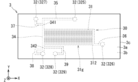
- FIG. 1 is a plan view schematically showing an example of a first flow channel device according to the first embodiment.
- FIG. FIG. 2 is a front view schematically showing an example of a first flow channel device according to the first embodiment;
- FIG. FIG. 3 is a plan view schematically showing an example of the configuration of the channel portion and the plurality of holes in the first channel device.
- FIG. 4 is a plan view showing a region IV surrounded by a rectangular dashed line in FIG.
- FIG. 5 is a flow chart showing an example of the flow of processing for separating particles using the first channel device.
- FIG. 6 is a flowchart showing an example of the flow of processing in the preparation process.
- FIG. 7 is a flowchart showing an example of the flow of processing in the pretreatment step.
- FIG. 8 is an image diagram showing an example of the connection state of each part in the connection process.
- FIG. 9 is a plan view schematically showing an example of the state of the first flow channel device before starting the pretreatment process.
- FIG. 10 is a plan view schematically showing an example of the state of the first channel device in the first stage of the pretreatment process.
- FIG. 11 is a plan view schematically showing an example of the state of the first channel device in the second stage of the pretreatment process.
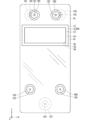
- FIG. 12 is a plan view schematically showing an example of the flow channel device according to the second embodiment.
- FIG. 13 is a plan view schematically showing an example of the second channel device.
- FIG. 14 is a cross-sectional view schematically showing an example of a virtual cross section of the flow channel device viewed in the +Y direction at position AA.
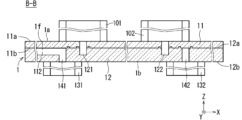
- FIG. 15 is a cross-sectional view schematically showing an example of a virtual cross section of the channel device viewed in the +Y direction at position BB.
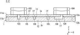
- FIG. 16 is a cross-sectional view schematically showing an example of a virtual cross section of the flow channel device viewed in the +Y direction at position EE.
- FIG. 17 is a cross-sectional view schematically showing an example of a hypothetical cross-section of the flow channel device at position CC viewed in a direction perpendicular to the +Z direction.
- FIG. 18 is a cross-sectional view schematically showing an example of a virtual cross section of the flow channel device viewed in the -X direction at position DD.
- FIG. 19 is a cross-sectional view schematically showing an example of a virtual cross section of the flow channel device viewed in the -X direction at position FF.
- FIG. 20 is a plan view schematically showing an example of a connecting member.
- FIG. 21 is a flowchart showing another first example of the processing flow in the pretreatment step.
- FIG. 22 is a plan view schematically showing an example of the state of the first flow channel device in the first stage of the pretreatment process according to the first example.
- FIG. 23 is a flowchart showing another second example of the processing flow in the pretreatment step.
- FIG. 24 is a plan view schematically showing another example of the configuration of the channel portion and the plurality of holes of the first channel device.
- FIG. 25 is a plan view schematically showing another example of the configuration of the channel portion and the plurality of holes
- Branching for separating specific types of particles (also referred to as first particles) from other types of particles (also referred to as second particles) from a liquid containing multiple types of particles (also referred to as a liquid to be treated) 2.
- a flow path device including a portion having fine flow paths also referred to as a flow path portion is known.
- the flow path section has, for example, a main flow path and a plurality of branch flow paths each narrower than the main flow path and connected to the main flow path. Then, for example, when the diameter of the first particles is larger than the diameter of the second particles, the width of each branch channel is larger than the diameter of the second particles and smaller than the diameter of the first particles. Two particles are introduced from the main channel into a plurality of branch channels and separated from the first particles flowing in the main channel.
- the resistance to the liquid flow from upstream to downstream in the main flow path is less than the resistance to liquid flow.
- the liquid to be treated is supplied upstream of a portion (also referred to as a branched portion) where a plurality of branched flow paths of the main flow path are connected, at least one It is difficult for the liquid to flow in the branched flow paths of the part, and it is easy for the liquid to flow downstream in the main flow path.
- the second particles are difficult to be introduced from the main flow path into the plurality of branch flow paths in the branched flow paths through which the liquid is difficult to flow, and the first particles and the second particles are not sufficiently separated. obtain.
- a predetermined liquid also referred to as a pretreatment liquid
- pretreatment Also called
- the resistance to the flow of the pretreatment liquid from upstream to downstream in the main flow path is such that the flow of the pretreatment liquid from upstream to downstream in each branch flow path is Less than resistance to flow.
- the pretreatment liquid is supplied upstream of the branched portion of the main channel, the presence of air makes it difficult for the pretreatment liquid to flow in the plurality of branched channels, and the pretreatment liquid is not allowed to flow downstream in the main channel. flows easily. Therefore, for example, it is not easy to fill the plurality of branch channels with the pretreatment liquid by supplying the pretreatment liquid to the main channel.
- the flow path device when the flow path device is made of a specific material such as polydimethylsiloxane (PDMS), the flow path device enclosed in the vacuum pack is taken out from the vacuum pack and then subjected to a predetermined tolerance.
- PDMS polydimethylsiloxane
- the predetermined allowable time is set to, for example, about 10 minutes to 30 minutes, and complicated work such as strict time management after opening the vacuum pack is required.
- the entire flow path device is placed in a vacuum chamber, and the inside of the vacuum chamber is depressurized by a vacuum pump to evacuate the inside of the flow path portion to a vacuum.
- a vacuum pump is connected to a part of the openings connected to the flow path in the flow path device and all remaining openings are closed, and then the inside of the flow path is evacuated by the vacuum pump.
- a mode in which vacuuming is performed to create a vacuum is also conceivable.
- a large-scale apparatus is required in a mode in which the inside of the flow channel is evacuated immediately before use of these flow channel devices. In particular, when the number of openings connected to the channel portion in the channel device is large, the size and complexity of the device and the complexity of control are caused.
- the flow path device can be easily filled with a liquid in a relatively narrow flow path in the flow path portion as a preparation prior to use for its original purpose.
- the inventors of the present disclosure have created a technology that can easily fill the relatively thin channels in the channel portion with liquid in preparation for using the channel device.
- the drawings include diagrams with a right-handed XYZ coordinate system attached for convenience.
- the +Z direction is adopted as vertically upward (also simply referred to as upward).
- the vertically downward direction is also expressed as the -Z direction.
- the direction opposite to the X direction is also expressed as the -X direction.
- a direction opposite to the Y direction is also expressed as a -Y direction.
- a part of the flow path device is omitted in each of the cross-sectional views of FIGS. 14 to 19 due to breakage.
- the "channel" has a structure through which liquid flows.
- the length of the channel in the direction orthogonal to the direction in which the channel extends is called the width of the channel.
- a relatively small width of the channel means that the channel is relatively thin, and a relatively large width of the channel means that the channel is relatively thick.
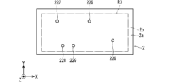
- FIG. 1 is a plan view schematically showing an example of a channel device (also referred to as a first channel device) 3 as a separation device according to the first embodiment.
- FIG. 2 is a front view schematically showing an example of the first flow channel device 3 according to the first embodiment.
- the first flow channel device 3 has, for example, a plate-like shape.
- the first flow channel device 3 includes, for example, a surface (also referred to as a first upper surface) 3a, a surface opposite to the first upper surface 3a (also referred to as a first lower surface) 3b, a first upper surface 3a and a first lower surface 3b. and a surface (also referred to as a first side surface) 3c connecting the .
- the outer surface of the first flow channel device 3 is composed of the first upper surface 3a, the first lower surface 3b, and the first side surface 3c.
- the first upper surface 3a is located on the +Z direction side of the first lower surface 3b.
- the first upper surface 3a faces the +Z direction. In other words, the first upper surface 3a has a normal along the +Z direction.
- the first lower surface 3b faces the -Z direction. In other words, the first lower surface 3b has a normal along the -Z direction.
- Each of the first upper surface 3a and the first lower surface 3b has, for example, a flat and rectangular shape.
- the thickness of the first flow path device 3 is, for example, about 1 millimeter (mm) to 5 mm.
- the thickness of the first flow channel device 3 is the length along the +Z direction of the first flow channel device 3 .
- the width of each of the first upper surface 3a and the first lower surface 3b of the first flow channel device 3 is, for example, approximately 10 mm to 50 mm.
- the width of the first upper surface 3a is the length along the +X direction of the first upper surface 3a.
- the width of the first lower surface 3b is the length along the +X direction of the first lower surface 3b.
- Each length of the first upper surface 3a and the first lower surface 3b of the first flow channel device 3 is, for example, about 10 mm to 30 mm.
- the length of the first upper surface 3a is the length along the +Y direction of the first upper surface 3a.
- the length of the first lower surface 3b is the length along the +Y direction of the first lower surface 3b.
- the first flow channel device 3 includes a flow channel portion 30 that is not open on the outer surface of the first flow channel device 3, and a flow channel portion 30 that communicates with the flow channel portion 30 and is open on the outer surface of the first flow channel device 3. and a plurality of holes 32 which are provided.
- the expression "the first part communicates with the second part” means that the first part communicates with the second part in a state in which a fluid such as a liquid can flow between the first part and the second part.
- a form in which the first part is directly connected to the part of, or a state in which a fluid can flow between the first part and the second part It means a form in which two parts are connected.
- each of the first part, the second part and the third part applies a part through which a fluid can flow, such as a channel or a hole.
- the third portion may be a portion combining two or more channels, a portion combining one or more channels and one or more holes, or a portion combining two or more channels. It may be a part in which the holes are combined.
- the channel portion 30 is located inside the first channel device 3 . From another point of view, for example, the channel portion 30 does not open to either the first upper surface 3a or the first lower surface 3b. In FIG. 2, the structure of the flow path part 30 is simplified and shown.
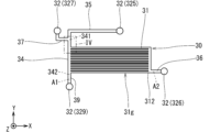
- FIG. 3 is a plan view schematically showing an example of the configuration of the channel portion 30 and the plurality of holes 32 in the first channel device 3.
- FIG. 3 the outer edge of the first flow path device 3 is omitted, and the outer edges of the flow path section 30, the two introduction holes 325, 327 and the three discharge holes 326, 328, 329 are drawn with solid lines.
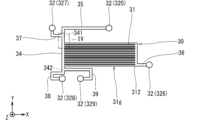
- FIG. 4 shows a portion of the flow path section 30. As shown in FIG. In FIG. 4, the outer edges of the main channel 34, the plurality of branch channels 31 and the two channels 35, 37 are drawn with solid lines.
- the channel part 30 has a configuration in which a plurality of groove-shaped channels that are not open on the outer surface of the first channel device 3 are connected.
- the channel section 30 includes, for example, a channel (also referred to as a main channel) 34 as a first channel and a plurality of channels (also referred to as branch channels) 31 as a plurality of second channels.
- the main channel 34 is, for example, a linear channel extending along the -Y direction as the first direction.
- the main flow path 34 has an upstream portion (also referred to as a first upstream portion) 341 and a downstream portion (also referred to as a first downstream portion) 342 .
- the main channel 34 extends in the ⁇ Y direction as the first direction from the first upstream portion 341 toward the first downstream portion 342 .
- Each of the plurality of branch channels 31 is, for example, connected to the main channel 34 and thinner than the main channel 34 .
- each of the plurality of branch flow paths 31 has a second direction perpendicular to the -Y direction, which is the first direction between the first upstream portion 341 and the first downstream portion 342 of the main flow path 34. is opened on the side surface of +X direction.
- the main channel 34 has a plurality of portions (also referred to as connection portions) C1 to which the plurality of branch channels 31 are connected.
- each of the plurality of branch channels 31 branches off from the main channel 34 at different positions in the -Y direction as the first direction.
- the plurality of connecting portions C1 to which the plurality of branch flow paths 31 are connected are present at different positions in the -Y direction as the first direction.
- each of the plurality of branch flow paths 31 extends along the +X direction as the second direction. From another point of view, the plurality of branch channels 31 are arranged along the -Y direction as the first direction.
- the plurality of branched flow paths 31 constitute, for example, a group of branched flow paths 31 (also referred to as a branched flow path group) 31g.
- the number of the plurality of branch flow paths 31 is set, for example, from tens to hundreds. In FIGS. 1 and 3, 13 branch channels 31 are drawn for convenience.
- the plurality of holes 32 are, for example, an introduction hole 327 as a first introduction hole, an introduction hole 325 as a second introduction hole, a discharge hole 329 as a first discharge hole, and a discharge hole 326 as a second discharge hole. and a discharge hole 328 as a third discharge hole.
- the introduction hole 327 communicates with, for example, the first upstream portion 341 of the main flow path 34 .
- the introduction hole 327 is connected to the first upstream portion 341 via the channel 37 .
- the channel portion 30 includes the channel 37 as the third channel connecting the introduction hole 327 as the first introduction hole and the first upstream portion 341 .
- channel 37 is thicker than each branch channel 31 .
- the diameter of the introduction hole 327 is set equal to or greater than the width of the channel 37 .
- the portion of the channel 37 connected to the first upstream portion 341 opens on the side surface of the main channel 34 opposite to the +X direction as the second direction. In the examples of FIGS.
- the channel 37 has a portion extending from the introduction hole 327 along the ⁇ Y direction as the first direction and a portion extending along the +X direction opposite to the second direction.
- the portion connected to the first upstream portion 341 is an L-shaped flow path connected in the order of this description. In other words, the channel 37 extends in order of -Y direction and +X direction.
- the introduction hole 325 communicates with, for example, the first upstream portion 341 of the main flow path 34 .
- the introduction hole 325 is connected to the first upstream portion 341 via the channel 35 .
- the channel portion 30 includes the channel 35 as the fourth channel connecting the introduction hole 325 as the second introduction hole and the first upstream portion 341 .
- channel 35 is thicker than each branch channel 31 .
- the diameter of the introduction hole 325 is set equal to or greater than the width of the channel 35 .
- the portion of the flow path 35 connected to the first upstream portion 341 extends along the -Y direction as the first direction.
- the channel 35 is connected to the first upstream portion 341 of the main channel 34 in the -Y direction as the first direction. More specifically, for example, the channel 35 has a portion extending from the introduction hole 325 along the ⁇ X direction opposite to the second direction and a portion extending along the ⁇ Y direction as the first direction. A part is an L-shaped flow path connected in the order of this description. In other words, the channel 35 extends in the -X direction and the -Y direction in that order.
- the discharge hole 329 communicates with, for example, the first downstream portion 342 of the main flow path 34 .
- the discharge hole 329 connects to the first downstream portion 342 via the channel 39 .
- the channel portion 30 includes the channel 39 as the fifth channel connecting the discharge hole 329 as the first discharge hole and the first downstream portion 342 .
- channel 39 is thicker than each branch channel 31 .
- the diameter of the discharge hole 329 is set equal to or greater than the width of the channel 39 .
- the portion of the channel 39 connected to the first downstream portion 342 opens on the side surface of the first downstream portion 342 in the +X direction as the second direction.
- the channel 39 is connected to the first downstream portion 342 and extends along the +X direction as the second direction and in the -Y direction as the first direction.
- a U-shaped flow path is formed by connecting a portion extending in the same direction and a portion extending in the ⁇ X direction opposite to the second direction, in the order of this description.
- the channel 39 extends in order of +X direction, -Y direction and -X direction.
- the discharge hole 326 communicates with, for example, a portion (also referred to as a second downstream portion) 312 of each of the plurality of branched flow paths 31 opposite to the main flow path 34 .
- the discharge holes 326 are connected to the second downstream portions 312 of each of the plurality of branched channels 31 via the channels 36 .
- the channel portion 30 includes the channel 36 as the sixth channel connecting the discharge hole 326 as the second discharge hole and the second downstream portion 312 in each of the plurality of branched channels 31. include. More specifically, for example, each of the plurality of branch channels 31 is connected to the channel 36 at different positions in the -Y direction as the first direction. For example, channel 36 is thicker than each branch channel 31 .
- the diameter of the discharge hole 326 is set equal to or greater than the width of the channel 36 . 1 and 3, the channel 36 is connected to the plurality of second downstream portions 312 of the plurality of branched channels 31 and extends linearly along the -Y direction as the first direction.
- the portion extending linearly along the +X direction as the second direction is an L-shaped flow path connected in the order of this description.
- the channel 36 extends in the -Y direction and the +X direction in that order.
- the discharge hole 328 communicates with, for example, the first downstream portion 342 of the main flow path 34 .
- outlet 328 connects to first downstream portion 342 via channel 38 .
- the channel portion 30 includes the channel 38 as the seventh channel connecting the discharge hole 328 as the third discharge hole and the first downstream portion 342 .
- channel 38 is thicker than each branch channel 31 .
- the diameter of the discharge hole 328 is set equal to or greater than the width of the channel 38 .
- the portion of the flow path 38 connected to the first downstream portion 342 extends along the -Y direction. In the example of FIGS.
- the channel 38 is connected to the first downstream portion 342 and extends along the -Y direction as the first direction, and the part opposite to the second direction - A portion extending along the X direction, a portion extending along the -Y direction as the first direction, and a portion extending along the +X direction as the second direction and connected to the discharge hole 328.
- a part is a channel connected in the order of this description. In other words, the channel 38 extends in the -Y direction, the -X direction, the -Y direction and the +X direction in this order.
- each of the two introduction holes 325, 327 and the three discharge holes 326, 328, 329 does not open to the first upper surface 3a and opens to the first lower surface 3b.
- the introduction hole 327 has a portion (also referred to as a first introduction port or a first inlet) 1i that opens in the first lower surface 3b.
- the introduction hole 325 has a portion (also referred to as a second introduction port or a second inlet) 2i that opens in the first lower surface 3b.
- the discharge hole 329 has a portion (also referred to as a first discharge port or a first outlet) 1o that opens in the first lower surface 3b.
- the discharge hole 326 has a portion (also referred to as a second discharge port or a second outlet) 2o that opens in the first lower surface 3b.
- the discharge hole 328 has a portion (also referred to as a third discharge port or a third outlet) 3o that opens in the first lower surface 3b.
- a liquid containing a plurality of types of particles P100 and P200 (see FIG. 4) (also referred to as liquid to be treated) is introduced into the first flow path device 3 .
- the first flow path device 3 separates the separation target particles P100, which are particles of a specific kind, from particles of other kinds (also referred to as particles of other kinds) P200 and discharges them.
- Plural types of particles may be three or more types.
- each of the separation target particles P100 and the other-type particles P200 is a particle of one type is exemplified.
- the pressing liquid is introduced into the first channel device 3 from the introduction hole 327 .
- the liquid to be treated is introduced into the first flow channel device 3 through the introduction hole 325 . Specific examples and functions of the pressing liquid will be described later.
- a pipe for supplying the pressing liquid is connected to the first flow path device 3 from the outside of the first flow path device 3. obtain.
- the first lower surface 3b of the first flow path device 3 is introduced in a plan view (hereinafter, unless otherwise specified, a plan view in the -Z direction).
- the introduction hole 325 When the liquid to be treated is introduced from the introduction hole 325 into the first flow path device 3, for example, a pipe for supplying the liquid to be treated is connected to the first flow path device 3 from the outside of the first flow path device 3. obtain.
- this pipe for example, on the first lower surface 3b of the first flow path device 3, when viewed from above, the introduction hole 325 is positioned in a state surrounding the Z axis, and in the +Z direction. There may be a protruding tubular portion.
- the liquid to be treated introduced into the first channel device 3 through the introduction hole 325 flows into the first upstream portion 341 of the main channel 34 via the channel 35 .
- the pressing liquid introduced into the first channel device 3 through the introduction hole 327 flows through the channel 37 into the first upstream portion 341 of the main channel 34 .
- An arrow Fp1 drawn with a two-dot chain line in FIG. 4 indicates the direction in which the pressing liquid is directed. This direction is along the +X direction.
- An arrow Fm1 drawn by a two-dot chain line thicker than the arrow Fp1 in FIG. 4 indicates the direction in which the main flow (also referred to as the main flow) of the liquid to be treated flowing through the main flow path 34 from the flow path 35 heads. The direction in which this main flow is directed is the direction along the -Y direction as the first direction.
- a rectangle drawn with a thin two-dot chain line in FIG. 4 virtually indicates the outer edge of the first upstream portion 341 .
- FIG. 4 schematically shows how the particles P100 to be separated are separated from each other when the diameter of the particles P100 to be separated is larger than the diameter of the other-type particles P200.
- the width of each branch channel 31 is larger than the diameter of the other-type particles P200 and smaller than the diameter of the separation target particles P100.
- the width of the branch channel 31 is the length of the branch channel 31 along the Y direction.
- each of the main channel 34 and the channel 35 is larger than the diameter of each of the separation target particles P100 and the other-type particles P200.
- the width of the main channel 34 is the length of the main channel 34 along the X direction perpendicular to the -Y direction as the first direction.
- the width of the channel 35 is the length of the channel 35 along the X direction in the vicinity of the main channel 34 .
- the width of the channel 35 is the length of the channel 35 along the Y direction at the position where the channel 35 extends along the -X direction.
- Most of the other-species particles P200 are introduced into any one of the plurality of branched flow paths 31 by being pushed in the +X direction while moving in the -Y direction as the first direction in the main flow path 34. . Most of the other-species particles P200 are discharged to the outside of the first flow channel device 3 from the discharge holes 326 via any one of the plurality of branch flow channels 31 and further through the flow channel 36 .
- the particles of other species P200 are introduced from the main flow channel 34 into any of the plurality of branch flow channels 31 and separated. It is separated from the target particle P100.
- the other-species particles P200 discharged from the discharge hole 326 to the outside of the first flow path device 3 are, for example, subjected to a specific treatment in another device connected directly to the discharge hole 326 or via another member such as a pipe. may be provided to or may simply be collected.
- the other-species particles P200 discharged from the discharge hole 326 to the outside of the first channel device 3 may be discarded, for example, directly or via another member such as a pipe.
- the separation target particles P100 are hardly introduced into the plurality of branch channels 31 and move in the main channel 34 in the -Y direction as the first direction. Most of the particles P100 to be separated pass through the main channel 34 and further through the channel 39 and are discharged from the discharge hole 329 to the outside of the first channel device 3 .
- the width of the channel 39 is larger than the separation target particles P100.
- the separation target particles P100 that have reached the first downstream portion 342 enter the flow path 39 instead of the flow path 38 by the same action as the other-type particles P200 introduced into any of the plurality of branch flow paths 31 in the main flow path 34. influx.
- the particles to be separated P100 discharged from the discharge hole 329 to the outside of the first channel device 3 are subjected to a specific treatment in another device connected directly to the discharge hole 329 or via another member such as a pipe, for example. may be provided to or may simply be collected.
- the composition (also referred to as the residual composition) of the liquid to be treated excluding the other-species particles P200 flowing to any of the plurality of branched flow paths 31 and the separation-target particles P100 flowing to the flow path 39 flows into the flow path 38. influx.
- This residual composition passes through channel 38 and is discharged from discharge hole 328 .
- the remaining composition discharged from the discharge hole 328 to the outside of the first channel device 3 is, for example, in another device connected directly to the discharge hole 328 or via another member such as a pipe, It may be subjected to a specific treatment or simply recovered.
- the remaining composition discharged from the discharge hole 328 to the outside of the first channel device 3 may be discarded, for example, directly or via another member such as a pipe.
- a flow that introduces the liquid to be treated into the branch channel 31 (also referred to as an introduction flow) is used.
- the introduced flow can contribute to the separation of the separation target particles P100 and the other-type particles P200 by the main channel 34 and the plurality of branch channels 31 .
- the inflow is indicated in FIG. 4 by the hatched region Ar1 using sand.
- the state of the introduced flow indicated by the area Ar1 in FIG. 4 is merely an example, and the flow velocity and flow rate of the liquid to be treated introduced from the flow channel 35 to the main flow channel 34 and the flow rate from the flow channel 37 to the main flow channel 34 are shown. It can change according to the flow velocity and flow rate of the pressing liquid introduced into the first upstream portion 341 .
- the pressing liquid presses the liquid to be processed against the plurality of branched flow paths 31 in the +X direction from the side opposite to the plurality of branched flow paths 31 .
- the pressing liquid can contribute to the generation of the inductive flow.
- the main flow path 34 extends in the -Y direction as the first direction.
- a portion of the channel 35 connected to the first upstream portion 341 of the main channel 34 extends along the -Y direction as the first direction.
- Each of the plurality of branch channels 31 is open on the side surface in the +X direction as the second direction between the first upstream portion 341 and the first downstream portion 342 of the main channel 34 .
- the flow path 37 is opened on the side surface of the first upstream portion 341 of the main flow path 34 in the ⁇ X direction opposite to the second direction.
- the liquid to be processed containing a plurality of types of particles is supplied to the main flow path 34 via the introduction hole 325 .
- a liquid flow can be generated at 34 that forces particles of multiple species toward multiple branch channels 31 .
- the other-type particles P ⁇ b>200 which are particles having a diameter smaller than the width of each branch flow channel 31 among the plurality of types of particles, easily flow into the plurality of branch flow channels 31 .
- separation target particles P100 which are particles with a diameter larger than the width of each branch channel 31, and particles with a diameter smaller than the width of each branch channel 31 can be easily separated from the other kind of particles P200.
- the portion of the channel 39 connected to the first downstream portion 342 of the main channel 34 is in the +X direction as the second direction of the first downstream portion 342. It is open on the sides. For this reason, for example, the action of the introduction flow in the main channel 34 facilitates the separation target particles P ⁇ b>100 having a larger diameter than the width of each branch channel 31 to flow into the channel 39 . Thereby, for example, the separation target particles P100 can be easily discharged from the discharge hole 329 to the outside of the first flow path device 3 through the flow path 39 .
- separation target particles P100 which are particles with a diameter larger than the width of each branch channel 31, and particles with a diameter smaller than the width of each branch channel 31 can be easily separated from the other kind of particles P200.
- the width of the flow introduced into the main channel 34 is shown as the width W1 in the vicinity of the region where the main channel 34 branches into the plurality of branch channels 31 .
- the width of the introduced flow in the main channel 34 is the length of the introduced flow along the X direction.
- the width W1 can be set, for example, by adjusting the cross-sectional areas and lengths of the main channel 34 and the plurality of branch channels 31 and by adjusting the flow rates of the liquid to be treated and the pressing liquid.
- the width W1 is exemplified by a width that does not include the center of gravity of the separation target particles P100 but includes the center of gravity of the other-type particles P200 in the region Ar1 of the introductory flow.
- Blood which is a liquid containing multiple types of particles, is used as an example of the liquid to be processed.
- the particles P100 to be separated are white blood cells and the other-species particles P200 are red blood cells. Measurement of the number of white blood cells is employed as an example of specific processing for the separation target particles P100.
- Plasma or the like is adopted as an example of the residual composition that flows through the channel 38 and is discharged from the first channel device 3 through the discharge hole 328 .
- phosphate-buffered saline (PBS) is employed as an example of the pressing liquid.
- a liquid obtained by adding other components to PBS may be applied as the pressing liquid.
- other components for example, ethylenediaminetetraacetic acid (EDTA) may be applied as the second component, and bovine serum albumin (BSA) may be applied as the third component. good.
- EDTA ethylenediaminetetraacetic acid
- BSA bovine serum albumin
- the position of the center of gravity of red blood cells is, for example, about 2 micrometers ( ⁇ m) to 2.5 ⁇ m from the outer edge of red blood cells.
- the maximum diameter of red blood cells is, for example, about 6 ⁇ m to 8 ⁇ m.
- the centroid position of the leukocyte is, for example, a position about 5 ⁇ m to 10 ⁇ m from the outer edge of the leukocyte.
- the maximum diameter of white blood cells is, for example, about 10 ⁇ m to 30 ⁇ m. From the viewpoint of separating erythrocytes and leukocytes in the blood, a value of about 2 ⁇ m to 15 ⁇ m is adopted as the width W1 of the introduced flow.
- the cross-sectional area of the virtual cross section along the XZ plane of the main channel 34 is, for example, about 300 square micrometers ( ⁇ m 2 ) to 1000 ⁇ m 2 .
- the length of the main channel 34 along the Y direction is, for example, about 0.5 mm to 20 mm.
- a cross-sectional area of a virtual cross section along the YZ plane of the branch flow path 31 is, for example, about 100 ⁇ m 2 to 500 ⁇ m 2 .
- the length of the branch channel 31 along the X direction is, for example, about 3 mm to 25 mm.
- the flow velocity of the liquid to be treated flowing in the -Y direction as the first direction in the main channel 34 is, for example, about 0.2 meters per second (m/s) to 5 m/s.
- the flow rate of the liquid per unit time in the main channel 34 is, for example, about 0.1 microliters per second ( ⁇ l/s) to 5 ⁇ l/s.
- the total volume of the flow path section 30, the two introduction holes 325, 327 and the three discharge holes 326, 328, 329 is reduced from 0.5 microliters ( ⁇ l) to about 2 ⁇ l.
- the total volume of the main channel 34, the two channels 35, 37 and the two introduction holes 325, 327 can be set to about 0.07 ⁇ l to 0.3 ⁇ l.
- the total volume of the main flow path 34, the four flow paths 35, 37, 38, 39, the two introduction holes 325, 327 and the two discharge holes 328, 329 is set to about 0.1 ⁇ l to 0.5 ⁇ l. obtain.
- PDMS has excellent transferability when performing resin molding using a mold.
- the transferability is a property of forming fine unevenness corresponding to a fine pattern of a mold in a resin molded article.
- the first flow path device 3 includes, for example, a plate-like first portion having, on one side, fine unevenness corresponding to the pattern of the flow path section 30, two introduction holes 325 and 327 and three discharge holes 326, 328, It can be manufactured by joining a plate-like second portion having five through holes corresponding to 329 in such a manner that one side of the second portion covers the fine unevenness of the first portion.
- the first portion having fine unevenness on one side can be produced, for example, by resin molding.
- the second portion having five through-holes may be produced, for example, by resin molding, or may be produced by forming five through-holes in a plate-like member formed by resin molding by punching or the like. good too.
- the bonding of the first part and the second part is achieved, for example, by surface modification to one side of the first part and one side of the second part, and contacting one side of the first part with one side of the second part, using an adhesive.
- can be realized without Surface modification is achieved by, for example, irradiation with oxygen plasma or irradiation with ultraviolet (UV) light using an excimer lamp.
- UV ultraviolet
- one side of the first portion and one side of the second portion are made of the same kind of resin, the bonding strength between the one side of the first portion and the one side of the second portion using surface modification is improved. obtain.
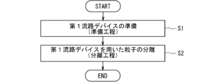
- FIG. 5 is a flowchart showing an example of the flow of processing for separating particles using the first channel device 3. As shown in FIG.
- a step of preparing the first channel device 3 (also referred to as a preparation step) in step S1 and separation of particles using the first channel device 3 in step S2 are performed.
- the steps (also referred to as separation steps) are performed in the order described.
- the preparation process is a process for preparing the first flow path device 3 in advance in order to perform the separation process.
- a process of introducing the liquid (also referred to as pretreatment liquid) into the channel section 30 (also referred to as an introduction process) is performed.
- This introduction process is a process for washing the first channel device 3 and realizing a smooth flow of the liquid to be treated in the channel section 30 (particularly the narrow branch channels 31) in the separation step.
- the pretreatment liquid is also used as the pressing liquid.
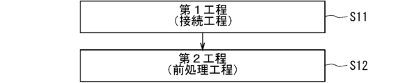
- FIG. 6 is a flowchart showing an example of the flow of processing in the preparation process performed in step S1 of FIG.
- a connecting process as a first process in step S11 and a pretreatment process as a second process in step S12 are performed in this order.
- the method for preparing the first flow path device 3 has a connecting step as a first step and a pretreatment step as a second step.
- FIG. 7 is a flow chart showing an example of the flow of processing in the pretreatment step of step S12 of FIG.
- FIG. 8 is an image diagram showing an example of the connection state of each part in the connection process.
- the first liquid supply unit 4 for supplying the pretreatment liquid to the main flow path 34 through the introduction hole 327 is connected to the introduction hole 327, and the plurality of branch flow paths 31 and A liquid suction unit 5 for sucking the pretreatment liquid through the discharge hole 326 is connected to the discharge hole 326 .
- the first liquid supply section 4 is connected to the introduction hole 327 via a pipe 4c or the like.
- a connector for connecting to the introduction hole 327 As shown in FIG.
- the liquid suction part 5 is connected to the discharge hole 326 via a tube 5c or the like.
- each pipe 4c, 5c is drawn with a thin two-dot chain line for convenience, and the direction in which the pretreatment liquid flows in each pipe 4c, 5c is indicated by an arrow drawn with a thin two-dot chain line.
- the introduction hole 325 may be connected to the second liquid supply section 6 for supplying the liquid to be treated to the main flow path 34 via the introduction hole 325 .
- the second liquid supply section 6 is connected to the introduction hole 325 via a pipe 6c or the like.
- a connector for connecting to the introduction hole 325.
- the second liquid supply unit 6 and the pipe 6c are drawn with a thin two-dot chain line for convenience, and the direction in which the liquid to be treated flows in the pipe 6c is indicated by an arrow drawn with a thin two-dot chain line.
- the discharge hole 329 may be connected directly or via another member such as a pipe to a device for performing a specific treatment on the particles P100 to be separated or recovering the particles P100 to be separated.
- vent 328 may have a device directly or otherwise, such as a tube, to perform specific treatment or recovery of the residual composition discharged from vent 328. You may connect through a member.
- a mechanism capable of supplying the pretreatment liquid using a pump such as a syringe pump or a flanger pump, for example, is applied to the first liquid supply unit 4 .
- the operation of the first liquid supply section 4 can be controlled according to a signal from the control section 7, for example.
- the control unit 7, for example starts and stops the supply of the pretreatment liquid toward the main flow path 34 by the first liquid supply unit 4, and causes the first liquid supply unit 4 to supply the pretreatment liquid toward the main flow
- the supply amount of the treatment liquid per unit time (also referred to as the first supply rate) can be controlled.
- a mechanism capable of sucking liquid and gas using a pump such as a diaphragm pump or a syringe pump is applied to the liquid suction unit 5 .
- the gas sucked by the pump exists mainly in the channel 37 , the main channel 34 , the branch channel 31 and the channel 36 before the pretreatment liquid reaches the discharge hole 326 .
- This gas needs to be sucked out before the pretreatment liquid reaches the drain hole 326 and begins directly pumping the pretreatment liquid.
- the expression “liquid suction” includes sucking gas present in a flow path as a step prior to directly sucking liquid using a pump.
- the operation of the liquid suction section 5 can be controlled according to a signal from the control section 7, for example.
- control unit 7 controls, for example, the start and stop of suction of the pretreatment liquid from the main flow channel 34 by the liquid suction unit 5 via the plurality of branch flow channels 31, the flow channel 36 and the discharge hole 326, and the liquid It is possible to control the amount of pretreatment liquid sucked per unit time (also referred to as first suction speed) from the main channel 34 by the suction unit 5 via the plurality of branch channels 31 , channels 36 and discharge holes 326 .
- a mechanism capable of supplying the liquid to be treated using a pump such as a syringe pump or a flanger pump, for example, is applied to the second liquid supply section 6 .
- the operation of the second liquid supply section 6 can be controlled according to a signal from the control section 7, for example.
- the control unit 7 controls, for example, the start and stop of the supply of the liquid to be treated toward the main flow path 34 by the second liquid supply unit 6 and the The supply amount of the treatment liquid per unit time (also referred to as a second supply rate) can be controlled.
- the control unit 7 can control the operations of elements such as the first liquid supply unit 4, the liquid suction unit 5, and the second liquid supply unit 6, for example.
- the control unit 7 may be, for example, a computer or the like, or may be a control circuit.
- Control unit 7 includes at least one processor to provide control and processing power to perform various functions, as described in further detail below.
- At least one processor may be implemented in a single integrated circuit (IC), or multiple ICs and/or discrete circuits communicatively coupled. At least one processor may be implemented according to various known techniques.
- a processor includes one or more circuits or units configured in a manner to perform one or more data computing procedures or processes, such as by executing instructions stored in associated memory.
- the processor may be firmware (eg, discrete logic components) configured in a form to perform one or more data computing procedures or processes.
- the processor is one or more of processors, controllers, microprocessors, microcontrollers, Application Specific Integrated Circuits (ASICs), digital signal processors, programmable logic devices, field programmable A gate array, or any combination of these devices or configurations, or other known combinations of devices and configurations, may be included to perform the functions described below.
- ASICs Application Specific Integrated Circuits
- digital signal processors programmable logic devices, field programmable A gate array, or any combination of these devices or configurations, or other known combinations of devices and configurations, may be included to perform the functions described below.
- control unit 7 includes a CPU (Central Processing Unit) 71 and a storage unit 72, for example.
- the storage unit 72 includes non-temporary recording media readable by the CPU 71, such as ROM (Read Only Memory) and RAM (Random Access Memory).
- the storage unit 72 stores a program P1 and the like for controlling the first liquid supply unit 4, the liquid suction unit 5, the second liquid supply unit 6, and the like.
- Various functions of the control unit 7 are realized by the CPU 71 executing the program P1 in the storage unit 72 .
- control unit 7 may include multiple CPUs 71 .
- control unit 7 may include at least one DSP (Digital Signal Processor).
- DSP Digital Signal Processor
- all functions of the control unit 7 or some functions of the control unit 7 may be realized by a hardware circuit that does not require software for realizing the functions.
- the storage unit 72 may also include a non-temporary computer-readable recording medium other than ROM and RAM.
- the storage unit 72 may include, for example, a small hard disk drive and/or SSD (Solid State Drive).
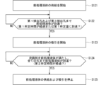
- steps S121 to S125 are performed in the order described.
- This pretreatment step can be realized, for example, by controlling the first liquid supply section 4 and the liquid suction section 5 by the control section 7 .
- FIGS. 9 to 11 are diagrams schematically showing an example of changes in the state of introduction of the pretreatment liquid into the first flow channel device 3 in the pretreatment step.
- FIG. 9 is a plan view schematically showing an example of the state of the first flow channel device 3 before starting the pretreatment process.
- FIG. 10 is a plan view schematically showing an example of the state of the first flow channel device 3 in the first stage of the pretreatment process.
- FIG. 11 is a plan view schematically showing an example of the state of the first flow channel device 3 in the second stage of the pretreatment process.
- the area where the pretreatment liquid is present is indicated by hatching with slanted lines rising to the right.
- FIGS. 10 and 11 the direction in which the pretreatment liquid flows is indicated by thin double-dashed arrows.
- step S121 an operation (also referred to as a supply operation) of supplying the pretreatment liquid to the main channel 34 via the introduction hole 327 by the first liquid supply unit 4 is started.
- the pretreatment liquid is supplied from the introduction hole 327 to the main flow path 34 via the flow path 37 .
- the pretreatment liquid is supplied toward the main flow path 34 through the introduction hole 327 by the first liquid supply section 4 at the first supply speed.
- the first supply rate is set, for example, from 100 microliters per minute ( ⁇ l/min) to 400 ⁇ l/min.
- the first supply rate may, for example, be constant or slightly fluctuate over time.
- each branch channel 31 of the channel section 30 has a smaller width than the other channels, and the presence of air in each branch channel 31 makes it difficult for the pretreatment liquid to flow. . Therefore, as shown in FIG. 10, the pretreatment liquid supplied from the introduction hole 327 to the main flow path 34 via the flow path 37 flows toward the introduction hole 325 via the flow path 35 and flows toward the main flow path 325 . Flow occurs through channel 34 and channel 39 in sequence to discharge hole 329 and through main channel 34 and channel 38 in sequence to discharge hole 328 .
- step S122 it is determined whether or not the pretreatment liquid has reached the discharge holes 329 and 328. This determination is made, for example, by the control unit 7 as to whether or not the first predetermined time has passed since the supply operation by the first liquid supply unit 4 was started, or whether the first liquid supply unit 4 has started the supply operation. This can be achieved by determining whether or not the amount of pretreatment liquid supplied by the supply unit 4 has reached the first predetermined amount.
- the first predetermined time and the first predetermined amount can be set, for example, according to the results of experiments using the first flow path device 3 or simulations related to the first flow path device 3 .
- step S ⁇ b>122 is repeated until the pretreatment liquid reaches the discharge holes 329 and 328 .
- the determination in step S122 is repeated until the supply amount reaches the first predetermined amount.
- step S123 the process proceeds to step S123.
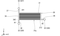
- the first predetermined time has elapsed since the start of the supply operation by the first liquid supply unit 4, or the pretreatment liquid by the first liquid supply unit 4 has elapsed since the start of the supply operation by the first liquid supply unit 4. If the supply amount reaches the first predetermined amount, the process proceeds to step S123. At this time, an area (also referred to as a first area) A1 from the introduction hole 327 to the two discharge holes 328 and 329 via the main flow path 34 is filled with the pretreatment liquid.
- two discharge holes 328 and 329 may be included in the first area A1.
- the first area A1 when the first area A1 is filled with the pretreatment liquid, air bubbles or air exist to such an extent that the pretreatment liquid is not divided in each channel and each hole 32 of the first area A1. state.
- the state in which the first area A1 is filled with the pretreatment liquid is the flow paths and the introduction holes of the first area A1. It may include a state in which air bubbles or air exist to the extent that the pretreatment liquid is not split at 327 .
- step S123 the liquid suction unit 5 starts an operation (also referred to as a suction operation) for sucking the pretreatment liquid from the main flow path 34 through the plurality of branch flow paths 31 and the discharge holes 326 .
- the suction operation is started after the pretreatment liquid is supplied from the introduction hole 327 to the discharge holes 328 and 329 through the main flow path 34 by the first liquid supply unit 4 .
- the liquid suction unit 5 sucks the pretreatment liquid from the main channel 34 through the plurality of branch channels 31 and the discharge holes 326 at the first suction speed.
- the first suction speed is set to be less than or equal to the first supply speed.
- the liquid suction section 5 supplies a plurality of branch flows from the main flow path 34 .
- the pretreatment liquid is sucked through the channel 31 and the discharge hole 326 at a first suction speed that is less than or equal to the first supply speed.
- the first suction speed is set, for example, from 50 ⁇ l/min to 200 ⁇ l/min.
- the first suction speed for example, may be constant over time, or may vary slightly.
- each branch flow path 31 has a smaller width than the other flow paths
- the pretreatment liquid is forcibly flowed in each branch flow path 31 by the suction operation of the liquid suction section 5. .
- the pretreatment liquid flows from the main channel 34 toward the discharge hole 326 through the plurality of branch channels 31 and the channels 36 in order.
- the area from the main flow path 34 to the discharge hole 326 via the plurality of branch flow paths 31 can be filled with pretreatment liquid.
- the discharge hole 326 may be included in the second area A2.
- the pretreatment liquid when the second area A2 is filled with the pretreatment liquid, bubbles or air exist to such an extent that the pretreatment liquid is not divided in each channel and the discharge hole 326 of the second area A2. state.
- the pretreatment liquid when the second area A2 does not include the discharge hole 326, the pretreatment liquid is not divided in each channel of the second area A2 when the second area A2 is filled with the pretreatment liquid. It may include the presence of air bubbles or air to some extent.
- the suction operation by the liquid suction section 5 is started.
- the pretreatment liquid is discharged from the main flow path 34 via the plurality of branch flow paths 31, respectively.
- step S ⁇ b>124 it is determined whether or not the pretreatment liquid has filled the flow path section 30 and reached all the holes 32 of the first flow path device 3 .
- This determination is realized, for example, by the control unit 7 determining whether or not the second predetermined time has elapsed from the start of the suction operation by the liquid suction unit 5 or the start of the supply operation by the first liquid supply unit 4. obtain.
- the second predetermined time can be set, for example, according to the results of experiments using the first flow path device 3 or simulations related to the first flow path device 3 .
- the state in which the flow path section 30 is filled with the pretreatment liquid may include, for example, a state in which bubbles or air exist in each flow path of the flow path section 30 to such an extent that the pretreatment liquid is not divided.
- step S ⁇ b>124 is repeated until the pretreatment liquid fills the flow path part 30 and reaches all the holes 32 of the first flow path device 3 .
- the determination in step S124 is repeated until the second predetermined time elapses from the start of the suction operation by the liquid suction unit 5 or the start of the supply operation by the first liquid supply unit 4 .
- step S125 when the pretreatment liquid fills the channel portion 30 and reaches all the holes 32 of the first channel device 3, the process proceeds to step S125.
- the process proceeds to step S125.
- a first area A1 extending from the introduction hole 327 to the two discharge holes 328 and 329 via the main flow path 34, and a second area A2 extending from the main flow path 34 to the discharge hole 326 via the plurality of branch flow paths 31, respectively. is filled with pretreatment liquid.
- step S125 the supply operation by the first liquid supply unit 4 and the suction operation by the liquid suction unit 5 are stopped.
- the liquid to be treated is introduced through the introduction hole 325 and the pressing liquid is introduced through the introduction hole 327 into the flow path section 30 of the first flow path device 3 .
- the liquid to be treated is supplied by the second liquid supply section 6 to the first upstream portion 341 of the main flow path 34 through the introduction hole 325 and the flow path 35 in order.
- the pressing liquid is supplied by the first liquid supply section 4 to the first upstream portion 341 of the main flow path 34 through the introduction hole 327 and the flow path 37 in this order.
- the other type of particles P200 among the plurality of types of particles contained in the liquid to be treated are introduced from the main flow path 34 into any of the plurality of branch flow paths 31. It is separated from the separation target particles P100. Particles to be separated P100 among the plurality of types of particles contained in the liquid to be treated are hardly introduced into the plurality of branched flow paths 31, but pass through the main flow path 34 and further through the flow path 39. It is discharged from the discharge hole 329 to the outside of the first channel device 3 .
- the method for preparing the first flow channel device 3 according to the first embodiment includes a connecting step as a first step and a pretreatment step as a second step.
- the first liquid supply unit 4 for supplying the pretreatment liquid to the main flow path 34 through the introduction hole 327 is connected to the introduction hole 327 , and the plurality of branch flow paths 31 and the discharge holes 326 are connected from the main flow path 34 .
- the liquid suction part 5 for sucking the pretreatment liquid is connected to the discharge hole 326 through the .
- the liquid suction unit 5 causes a plurality of branch flows from the main flow path 34.
- the pretreatment liquid is sucked through the channel 31 and the discharge hole 326 at a first suction speed that is less than or equal to the first supply speed.
- each branch flow path 31 has a smaller width than the other flow paths, the pretreatment liquid is forcibly flowed in each branch flow path 31 by the suction operation of the liquid suction section 5. .
- a first area A1 extending from the introduction hole 327 to the two discharge holes 328 and 329 via the main flow path 34, and a second area A2 extending from the main flow path 34 to the discharge hole 326 via the plurality of branch flow paths 31 respectively. Can be filled with pretreatment liquid.
- the preparation method of the first flow channel device 3 for example, from the main flow channel 34 through the plurality of branch flow channels 31 narrower than the other flow channels in the flow channel section 30 and the discharge holes 326 .
- a simple configuration is adopted in which the liquid suction part 5 for sucking the pretreatment liquid is connected to the discharge hole 326 .
- the relatively thin branch channels 31 in the channel portion 30 of the first channel device 3 can be quickly filled with the pretreatment liquid by the liquid suction portion 5 such as a pump connected to the discharge hole 326. can.
- a vacuum pump is connected to the openings of some of the holes and the remaining There is no need for a large-scale device or complicated control for vacuuming the inside of the channel section 30 with a vacuum pump in a state in which all the openings of the holes are blocked.
- each relatively narrow branch channel 31 in the channel portion 30 of the first channel device 3 can be easily filled with the pretreatment liquid.
- the first flow channel device 3 as the separation device according to the first embodiment is combined with the flow channel device (also referred to as the second flow channel device) 1 as the processing device to form a type of flow channel device.
- separation processing device 100 may be configured.
- FIG. 12 is a plan view showing an example of the separation processing device 100 according to the second embodiment.
- the separation processing device 100 includes, for example, a first channel device 3, a connection member 2, and a second channel device 1.
- the second flow channel device 1, the connection member 2, and the first flow channel device 3 are in a state of being stacked one on top of the other in the +Z direction in this order.
- the connection member 2 is positioned on the second flow path device 1 and the first flow path device 3 is positioned on the connection member 2 .
- the second flow path device 1 has a surface (also referred to as a second upper surface) 1a and a surface (also referred to as a second lower surface) 1b.
- the second upper surface 1a is located on the +Z direction side of the second lower surface 1b.
- the connection member 2 has a surface (also referred to as a third upper surface) 2a and a surface (also referred to as a third lower surface) 2b.
- the third upper surface 2a is located on the +Z direction side of the third lower surface 2b.
- the third lower surface 2b is in contact with the second upper surface 1a of the second flow path device 1.
- the third upper surface 2 a is in contact with the first lower surface 3 b of the first channel device 3 .
- the connection member 2 is interposed between the first lower surface 3b of the first channel device 3 and the second upper surface 1a of the second channel device 1.
- the third lower surface 2b and the second upper surface 1a are bonded by plasma bonding, optical bonding, or the like, for example.
- the first lower surface 3b and the third upper surface 2a are bonded by plasma bonding, optical bonding, or the like, for example.
- Oxygen plasma for example, is used for the plasma bonding described above.
- Ultraviolet light from, for example, an excimer lamp is used for the above optical bonding.
- the second flow path device 1 and the connection member 2 have, for example, a plate-like outer shape that is rectangular in plan view, similar to the first flow path device 3 .
- the second upper surface 1a, the second lower surface 1b, the third upper surface 2a and the third lower surface 2b are perpendicular to the +Z direction, like the first upper surface 3a and the first lower surface 3b.
- FIG. 13 is a plan view schematically showing an example of the second channel device 1.
- a region R2 surrounded by a rectangular dashed line indicates a position where the third lower surface 2b of the connecting member 2 is joined on the second upper surface 1a.
- the second flow channel device 1 for example, a region of the second upper surface 1a other than the region R2, the second lower surface 1b, and the side surface connecting the second upper surface 1a and the second lower surface 1b are used for separation processing. It constitutes the outer surface of the device 100 .
- the thickness of the second flow path device 1 is, for example, about 0.5 mm to 5 mm.
- the thickness of the second flow path device 1 is the length of the second flow path device 1 along the +Z direction.
- Each width of the second upper surface 1a and the second lower surface 1b is, for example, about 10 mm to 50 mm.
- the width of the second upper surface 1a is the length along the +X direction of the second upper surface 1a.
- the width of the second lower surface 1b is the length along the +X direction of the second lower surface 1b.
- Each length of the second upper surface 1a and the second lower surface 1b is, for example, about 20 mm to 100 mm.
- the length of the second upper surface 1a is the length along the +Y direction of the second upper surface 1a.
- the length of the second lower surface 1b is the length along the +Y direction of the second lower surface 1b.
- the second channel device 1 has, for example, six introduction holes 121, 122, 124, 126, 128, 129, two discharge holes 125, 127 and a stirring hole 123.
- Each of the three introduction holes 126, 128, 129 and the two discharge holes 125, 127 opens at the second upper surface 1a in the region R2.
- Each of the three introduction holes 121, 122, 124 and the stirring hole 123 opens on the second upper surface 1a at positions other than the region R2. In other words, none of the six introduction holes 121, 122, 124, 126, 128, 129, the two discharge holes 125, 127 and the stirring hole 123 are open on the second lower surface 1b.
- the second channel device 1 has three discharge holes 141, 142, 143, for example.
- Each of the three discharge holes 141, 142, 143 is open on the second lower surface 1b at positions other than the region R2. In other words, none of the discharge holes 141, 142, 143 are open on the second upper surface 1a.
- the second channel device 1 has, for example, a plurality of channels 1f.
- the multiple channels 1f include, for example, a stirring channel 115, eight channels 111, 112, 113, 114, 116, 117, 118, 119, a measurement channel 151 and a reference channel 152.
- Each of the plurality of flow paths 1f is a groove-shaped flow path that opens to neither the second upper surface 1a nor the second lower surface 1b.
- the channel 111 communicates with the introduction hole 121 and the discharge hole 127.
- Channel 112 communicates with inlet hole 128 and outlet hole 141 .
- Channel 113 communicates with inlet hole 122 and outlet hole 125 .
- Channel 114 communicates with inlet hole 126 and outlet hole 142 .
- the measurement channel 151 is a channel interposed between the channel 117 and the channel 119 .
- the measurement channel 151 has a direction in which the measurement channel 151 extends (also referred to as a first longitudinal direction).
- the first longitudinal direction is the direction along the ⁇ Y direction from channel 117 to channel 119 .
- the measurement channel 151 extends in the -Y direction.
- the measurement channel 151 is connected to the channel 117 at the end on the +Y direction side, and is connected to the channel 119 at the end on the side opposite to the +Y direction ( ⁇ Y direction side). A portion where the measurement channel 151 is connected to the channel 117 overlaps with the region R2 in plan view.
- the measurement flow path 151 has an area (also referred to as a first end area) E1 positioned at one end in the first longitudinal direction and an area opposite to the first end area E1 in the first longitudinal direction. and a region (also referred to as a second end region) E2 located at the end of the .
- the measurement channel 151 has a first end region E1 and a second end region E2 on both sides in the first longitudinal direction.
- the first end region E1 is located at the end of the measurement channel 151 on the +Y direction side
- the second end region E2 is located at the ⁇ It is located at the end on the Y-direction side.
- the introduction hole 129 is connected to the first end region E1 of the measurement channel 151 . Therefore, the introduction hole 129 is a hole that is connected to the measurement channel 151 and opens to the second upper surface 1a.
- the measurement channel 151 is connected to the channel 117 in the first end region E1.
- the first end region E1 of the measurement channel 151 is connected to the stirring channel 115 via part of the channels 117 and 116 .
- the expression "the first part is connected to the second part” means that the first part is connected to the second part in a state in which fluid can flow between the first part and the second part. directly connected, or in which the first portion is connected to the second portion via another portion (the third portion) such that fluid can flow between the first portion and the second portion; means the form in which Therefore, the stirring channel 115 communicates with the first end region E ⁇ b>1 of the measurement channel 151 .
- the channel 116 is interposed between the channel 117 and the reference channel 152 and connected to the stirring channel 115 between the channel 117 and the reference channel 152 .
- Channel 117 is interposed between measurement channel 151 and channel 116 .
- Channel 118 is connected to inlet 124 and intervenes between inlet 124 and reference channel 152 .
- the channel 119 is interposed between the discharge hole 143 and the measurement channel 151 and connected to the discharge hole 143 . Therefore, the discharge hole 143 is a hole that is connected to the measurement flow path 151 via the flow path 119 and opens to the second lower surface 1b. More specifically, the discharge hole 143 is connected to the second end region E2 of the measurement channel 151 via the channel 119 .
- the stirring channel 115 is a channel interposed between the stirring hole 123 and the channel 116 .
- the stirring channel 115 has a direction in which the stirring channel 115 extends (also referred to as a second longitudinal direction).
- the stirring flow path 115 meanders. Specifically, from the stirring hole 123 toward the channel 116, the stirring channel 115 is formed in the order along the +Y direction, the +X direction, the ⁇ Y direction, the +X direction and the +Y direction. The extending direction is changed.
- the agitation flow path 115 has a region (also referred to as a third end region) E3 located at one end in the second longitudinal direction, and a region opposite to the third end region E3 in the second longitudinal direction. and a region (also referred to as a fourth end region) E4 located at the end of the .
- the stirring channel 115 has a third end region E3 and a fourth end region E4 on both sides in the second longitudinal direction.
- the stirring channel 115 is connected to the measurement channel 151 via part of the channel 116 and the channel 117 in the third end region E3.
- the stirring channel 115 is connected to the stirring hole 123 in the fourth end region E4. Therefore, the stirring hole 123 is a hole communicating with the fourth end region E4 of the stirring channel 115 and opening to the second upper surface 1a.
- the reference channel 152 is interposed between the channel 116 and the channel 118 .
- the reference channel 152 extends in the +Y direction, is connected to the channel 116 on the +Y direction side, and is connected to the channel 118 on the side opposite to the +Y direction ( ⁇ Y direction side). .
- both the measurement channel 151 and the reference channel 152 extend in the +Y direction.
- the measurement channel 151 and the reference channel 152 may extend in different directions.
- FIG. 14 to 19 each show a virtual cross section of the separation processing device 100.
- FIG. 14 to 19 each show a virtual cross section of the separation processing device 100.
- the second flow path device 1 is configured, for example, by stacking a first plate member 11 and a second plate member 12 .
- the first plate-like member 11 and the second plate-like member 12 are stacked in the order shown in the -Z direction.
- the first plate-shaped member 11 is a plate-shaped member having a first surface 11a and a second surface 11b opposite to the first surface 11a.
- the first surface 11a is located on the +Z direction side of the second surface 11b.
- the second plate-like member 12 is a plate-like member having a third surface 12a and a fourth surface 12b opposite to the third surface 12a.
- the third surface 12a is located on the +Z direction side of the fourth surface 12b.
- the first plate-shaped member 11 and the second plate-shaped member 12 are in a state where a part of the third surface 12a is joined to the second surface 11b.
- the first plate-like member 11 and the second plate-like member 12 form an integrated second flow path device 1 .
- any welding method such as ultrasonic welding, laser welding, thermal welding or diffusion welding can be applied.
- the first surface 11a is the second upper surface 1a
- the fourth surface 12b is the second lower surface 1b.
- Each of the plurality of flow paths 1f is positioned between the second surface 11b and the third surface 12a.
- each of the agitation channel 115, the eight channels 111, 112, 113, 114, 116, 117, 118, 119, the measurement channel 151 and the reference channel 152 includes the second surface 11b and the second surface 11b. It is positioned between three surfaces 12a.
- Six introduction holes 121 , 122 , 124 , 126 , 128 , 129 , two discharge holes 125 , 127 and agitation hole 123 each penetrate first plate member 11 .
- Each of the three discharge holes 141 , 142 , 143 penetrates the second plate member 12 .
- the agitation channel 115 extends substantially in the +Y direction, extends slightly in the +X direction, extends substantially in the -Y direction, slightly extends in the +X direction, and further extends substantially in the +Y direction as it goes from the agitation hole 123 toward the flow channel 116 . , and connects to channel 116 .
- a portion of the agitation channel 115 connected to the channel 116 is inclined with respect to the +Y direction in such a manner that the part of the channel 115 is connected to the -X direction as it goes in the +Y direction.
- a portion of the channel 116 connected to the stirring channel 115 extends in the -X direction.
- the minor angle (also referred to as the first minor angle) formed by the channel 116 and the stirring channel 115 on the channel 117 side is A configuration that is larger than the minor angle (also referred to as the second minor angle) is adopted.
- the liquid pushed out from the stirring channel 115 to the channel 116 tends to flow toward the measurement channel 151 via the channel 117 . This is because the liquid moves through the channel more easily as the curvature of the channel is smaller.
- the second flow path device 1 has four cylinders 101, 102, 103, 104 that protrude in the +Z direction from the second upper surface 1a.
- the tube 101 is positioned so as to surround the introduction hole 121 around the Z axis in plan view.
- the cylinder 102 is positioned so as to surround the introduction hole 122 around the Z axis in plan view.
- the tube 103 is positioned so as to surround the agitation hole 123 around the Z-axis in plan view.
- the tube 104 is positioned so as to surround the introduction hole 124 around the Z axis in plan view.
- the second flow channel device 1 has three cylinders 131, 132, 133 protruding in the direction opposite to the +Z direction (-Z direction) on the second lower surface 1b.
- the tube 131 is positioned so as to surround the discharge hole 141 around the Z axis in plan view.
- the tube 132 is positioned so as to surround the discharge hole 142 around the Z axis in plan view.
- the tube 133 is positioned so as to surround the discharge hole 143 around the Z axis in plan view.
- FIG. 20 is a plan view showing an example of the connection member 2.
- a region R3 surrounded by a rectangular dashed line indicates the position where the first lower surface 3b is joined.
- connection member 2 has five through holes 225, 226, 227, 228, 229. Each of the five through holes 225, 226, 227, 228, 229 is a hole penetrating between the third upper surface 2a and the third lower surface 2b in the region R3.
- the connection member 2 has, for example, a sheet-like form.
- the through hole 227 is connected to the discharge hole 127 and also to the introduction hole 327 .
- the through hole 227 connects the discharge hole 127 and the introduction hole 327 . Therefore, the introduction hole 327 is connected to the introduction hole 121 via the through hole 227, the discharge hole 127, and the flow path 111 in this order.
- the through hole 225 is connected to the discharge hole 125 and also to the introduction hole 325 .
- the through hole 225 connects the discharge hole 125 and the introduction hole 325 . Therefore, the introduction hole 325 is connected to the introduction hole 122 via the through hole 225, the discharge hole 125, and the flow path 113 in this order.
- the through hole 226 is connected to the introduction hole 126 and also connected to the discharge hole 326 .
- the through hole 226 connects the discharge hole 326 and the introduction hole 126 . Therefore, the discharge hole 326 is connected to the discharge hole 142 via the through hole 226, the introduction hole 126, and the flow path 114 in this order.
- the through hole 229 is connected to the introduction hole 129 and also connected to the discharge hole 329 .
- the through hole 229 connects the discharge hole 329 and the introduction hole 129 . Therefore, the discharge hole 329 is connected to the measurement channel 151 through the through hole 229 and the introduction hole 129 in the order of this description.
- the through hole 228 is connected to the introduction hole 128 and also connected to the discharge hole 328 .
- the through hole 228 connects the discharge hole 328 and the introduction hole 128 . Therefore, the discharge hole 328 is connected to the discharge hole 141 through the through hole 228, the introduction hole 128, and the flow path 112 in this order.
- the liquid to be treated containing multiple types of particles P100 and P200 is introduced into the first flow path device 3 .
- the first flow path device 3 separates the separation target particles P100 from the other type particles P200 and discharges them.
- the second flow path device 1 is used, for example, for predetermined processing of the separation target particles P100.
- counting detecting the number of particles
- the separation target particles P100 themselves and the liquid containing the separation target particles P100 are also referred to below as "specimen.”
- the liquid containing the separation target particles P100 as particles of a specific type is hereinafter also referred to as "particle-containing liquid”.
- connection member 2 guides the separation target particles P100 (more specifically, the sample) discharged from the first flow path device 3 to the second flow path device 1.
- the pretreatment liquid is introduced from the introduction hole 121 as a process for preparing before introducing the liquid to be treated into the separation treatment device 100 .
- Introduction of this pretreatment liquid can contribute to cleaning of the separation treatment device 100 and smooth movement of the liquid to be treated and the sample in the first channel device 3 .
- the pressing liquid is introduced into the separation processing device 100 from the introduction hole 121 .
- the pretreatment liquid or pressing liquid introduced into the separation processing device 100 through the introduction hole 121 passes through the channel 111, the discharge hole 127, the through hole 227, the introduction hole 327 and the channel 37 in the order described. It flows into the main flow path 34 .
- the pretreatment liquid or the pressing liquid is introduced from the introduction hole 121 into the separation processing device 100
- the pretreatment liquid or the pressing liquid is introduced from the introduction hole 327 into the main flow path 34 via the flow path 37 .
- a first liquid supply part 4 for supplying liquid can be connected to the introduction hole 121 .
- the first liquid supply section 4 can be connected to the introduction hole 327 via the introduction hole 121 , the flow path 111 , the discharge hole 127 and the through hole 227 . Therefore, in the second embodiment, when connecting the first liquid supply part 4 to the introduction hole 327, the first liquid supply part 4 is introduced by connecting the first liquid supply part 4 to the introduction hole 121. It can be indirectly connected to hole 327 .
- a pipe 4 c for connecting the first liquid supply section 4 to the introduction hole 121 can be connected to the separation device 100 from outside the separation device 100 .
- connecting the first liquid supply unit 4 to the introduction hole 121 by the pipe 4c means that a fluid can flow between the first liquid supply unit 4 and the introduction hole 121 through the pipe 4c.
- a tube 101 for example, is used to connect the pipe 4c.
- the pretreatment liquid when the pretreatment liquid is introduced from the introduction hole 121 into the separation processing device 100 by the first liquid supply unit 4, the passage 111, the discharge hole 127, the through hole 227, and the flow path 111 from the introduction hole 121 , the pretreatment liquid can be supplied to the main channel 34 via the introduction hole 327 and the channel 37 at a first supply rate.
- the operation (supply operation) of supplying the pretreatment liquid at the first supply speed toward the main flow path 34 through the introduction hole 327 by the first liquid supply unit 4 can be performed.
- the pretreatment liquid when the pretreatment liquid is introduced from the introduction hole 121 into the separation treatment device 100, the pretreatment liquid is sucked from the main flow path 34 via the plurality of branch flow paths 31 and the discharge holes 326. can be connected to the discharge hole 142 .
- the liquid suction part 5 can be connected to the discharge hole 326 via the discharge hole 142 , the flow path 114 , the introduction hole 126 and the through hole 226 . Therefore, in the second embodiment, when connecting the liquid suction part 5 to the discharge hole 326 , the liquid suction part 5 is indirectly connected to the discharge hole 326 by connecting the liquid suction part 5 to the discharge hole 142 . can be connected.
- the pipe 5c for connecting the liquid suction part 5 to the discharge hole 142 can be connected to the separation device 100 from the outside of the separation device 100 .
- connecting the liquid suction part 5 to the discharge hole 142 through the pipe 5c means that the fluid can flow between the liquid suction part 5 and the discharge hole 142 via the pipe 5c.
- a tube 132 for example, is used to connect the pipe 5c.
- the pretreatment liquid can be sucked at a first suction speed equal to or lower than the first supply speed.
- an operation (suction operation) of sucking the pretreatment liquid from the main channel 34 by the liquid suction unit 5 via the plurality of branch channels 31 and the discharge holes 326 at a first suction speed equal to or lower than the first supply speed can be performed.
- a step (first step) of connecting the liquid suction part 5 to the discharge hole 326 can be performed.
- the first liquid supply unit 4 supplies the pretreatment liquid through the introduction hole 327 toward the main flow path 34 at the first supply speed.
- a step (second step) of sucking the pretreatment liquid from the main flow path 34 by the liquid suction unit 5 through the plurality of branch flow paths 31 and the discharge holes 326 at a first suction speed equal to or lower than the first supply speed is performed. can do.
- the second area A2 can be filled with pretreatment liquid.
- the method for preparing the first flow path device 3 included in the separation processing device 100 includes a connection step as the first step and a pretreatment step as the second step.
- the pretreatment liquid is supplied from the introduction hole 327 to the two discharge holes 328 and 329 through the main flow path 34 by the first liquid supply unit 4, the liquid A suction operation by the suction unit 5 can be started.
- the pretreatment liquid is discharged from the main flow path 34 via the plurality of branch flow paths 31, respectively.
- a second area A2 leading to the holes 326 can begin to fill with pretreatment liquid.
- both the first area A1 and the second area A2 in the first channel device 3 can be quickly filled with the pretreatment liquid.
- the liquid to be processed is introduced into the separation processing device 100 through the introduction hole 122 .
- the liquid to be treated introduced into the separation processing device 100 through the introduction hole 122 passes through the flow path 113, the discharge hole 125, the through hole 225, the introduction hole 325 and the flow path 35 in the order described, and enters the main flow path 34. influx.
- the second liquid supply section 6 for supplying the liquid to be processed to the main channel 34 through the introduction hole 325 can be connected to the inlet 122 .
- the second liquid supply section 6 can be connected to the introduction hole 325 via the introduction hole 122 , the flow path 113 , the discharge hole 125 and the through hole 225 . Therefore, in the second embodiment, for example, when connecting the second liquid supply section 6 to the introduction hole 325 , the second liquid supply section 6 is connected to the introduction hole 122 so that the second liquid supply section 6 can be indirectly connected to the inlet 325 .
- a pipe 6c for connecting the second liquid supply section 6 to the introduction hole 122 can be connected to the separation device 100 from the outside of the separation device 100 .
- connecting the second liquid supply portion 6 to the introduction hole 122 by the pipe 6c means that a fluid can flow between the second liquid supply portion 6 and the introduction hole 122 via the pipe 6c.
- a tube 102 is used to connect the pipe 6c.
- a stirring fluid (also referred to as a stirring fluid) flows into the separation processing device 100 from the stirring holes 123 .
- the agitation fluid flows out of the separation processing device 100 through the agitation holes 123 .
- the supply and discharge of the agitation fluid can be connected to the separation processing device 100 from outside the separation processing device 100 .
- a tube 103 for example, can be used for this tube connection.
- a dispersion liquid (also referred to as a dispersion liquid) is introduced from the introduction hole 124 into the separation processing device 100 .
- a pipe for supplying the dispersing liquid is connected to the separation processing device 100 from the outside of the separation processing device 100.
- a tube 104 for example, can be used to connect the pipes.
- the first flow path device 3 can separate the separation target particles P100 from the other types of particles P200 from the plurality of types of particles contained in the liquid to be treated and discharge them.
- the other-species particles P200 discharged from the discharge hole 326 in the first flow channel device 3 pass through the through hole 226, the introduction hole 126, and the flow channel 114 in the order described, and exit the discharge hole 142 of the second flow channel device 1. Ejected.
- the other-type particles P200 discharged from the discharge holes 142 may be subjected to a specific treatment, or may not be subjected to a specific treatment.
- the separation target particles P100 discharged from the discharge hole 329 in the first flow channel device 3 are introduced into the measurement flow channel 151 of the second flow channel device 1 via the through hole 229 and the introduction hole 129 in this order.
- the introduction hole 129 opens in the second upper surface 1a.
- the first flow channel device 3 is positioned on the second upper surface 1a of the second flow channel device 1.
- a discharge hole 329 open on the first lower surface 3 b of the first flow path device 3 is connected to an introduction hole 129 open on the second upper surface 1 a of the second flow path device 1 .
- the liquid to be treated is introduced into the flow channel portion 30 of the first flow channel device 3
- the liquid containing the separation target particles P100 separated from the liquid to be treated in the flow channel portion 30 also referred to as a specimen
- It can be supplied to the measurement channel 151 of the second channel device 1 via the hole 329 and the introduction hole 129 .
- the separation of the specimen from the liquid to be treated using the first flow path device 3 and the predetermined treatment of the separation target particles P100 using the second flow path device 1 can be performed efficiently.
- the remaining composition discharged from the discharge hole 328 in the first flow channel device 3 passes through the through hole 228, the introduction hole 128 and the flow channel 112 in the order described, and exits from the discharge hole 141 of the second flow channel device 1. Ejected.
- the remaining composition discharged from the discharge hole 141 may or may not be subjected to a specific treatment.
- the dispersion liquid introduced into the separation processing device 100 from the introduction hole 124 flows into the measurement channel 151 via the channel 118, the reference channel 152, the channels 116, and 117 in this order.
- the dispersion liquid is a liquid for dispersing the separation target particles P100 introduced from the introduction hole 129 in the measurement channel 151 .
- the term "dispersion" used herein is the opposite of the separation target particles P100 adhering to each other and aggregating. Dispersion of the separation target particles P100 can contribute to the simple, accurate, or simple and accurate execution of predetermined processing such as counting, which is exemplified in the second embodiment.
- the same liquid as the pressing liquid can be applied as the dispersing liquid.
- PBS is used as an example of the dispersing liquid.
- the dispersing liquid may be a liquid obtained by adding at least one of EDTA as a second component and BSA as a third component to PBS.
- the stirring fluid introduced from the stirring hole 123 into the separation processing device 100 flows into the stirring channel 115 .
- the agitation fluid reciprocates inside the agitation channel 115 by manipulation from the outside. Air is employed as an example of the agitation fluid.
- the agitation fluid reciprocates in the agitation channel 115 by controlling the air pressure in the agitation hole 123 .
- the agitating fluid is added to the dispersing liquid containing the separation target particles P100 in the region from the agitating flow path 115 to the measurement flow path 151 via the flow paths 116 and 117 in order to promote the dispersion of the sample in the dispersing liquid.
- It is a fluid for stirring.
- the stirring fluid is a fluid for stirring a liquid (particle-containing liquid) containing the separation target particles P100 as particles of a specific kind.
- the same liquid as the dispersing liquid and the pressing liquid may be applied as the stirring fluid. If the liquid to be treated is blood, PBS is adopted as an example of the stirring fluid.
- the inflow and outflow of PBS through the agitation hole 123 causes the PBS to reciprocate in the agitation channel 115 .
- stirring fluid reciprocates inside stirring channel 115 , stirring of the dispersing liquid and the specimen can be promoted in at least part of stirring channel 115 , channels 116 and 117 , and measurement channel 151 .
- a specimen containing particles of a specific type is introduced through the introduction hole 129 into the region of the measurement channel 151 on the side of the first end region E1.
- the dispersion liquid and the sample agitation with can be facilitated.
- Stirring the dispersing liquid and the sample can contribute to, for example, dispersing the separation target particles P100 using the dispersing liquid.
- the agitating fluid may be a liquid of PBS plus at least one of EDTA as a second component and BSA as a third component.
- the specimen and the dispersion liquid advance inside the measurement channel 151 toward the channel 119 .
- the stirring fluid may also proceed inside the measurement channel 151 toward the channel 119 .
- the measurement channel 151 is used for predetermined processing on the separation target particles P100.
- the predetermined process includes, for example, a process of measuring the number of separation target particles P100 in the sample positioned in a specific region of the measurement channel 151 by optical measurement.
- the sample and the dispersion liquid are discharged from the measurement channel 151 through the channel 119 and through the discharge hole 143.
- the discharge hole 143 opens to the fourth surface 12b.
- the stirring fluid may also be discharged from the measurement flow path 151 via the flow path 119 and discharged from the discharge hole 143 .
- the separation target particles P100 discharged from the discharge hole 143 may be subjected to a specific process, or may not be subjected to a specific process.
- Each of the first plate member 11 and the second plate member 12 can be manufactured by resin molding or the like.
- FIG. 21 is a flow chart showing another example (also referred to as a first example) of the processing flow in the pretreatment process performed in step S12 of FIG. 6 above.
- steps S121, S122A, S123, S124 and S125 are performed in the order described.
- the flow chart of FIG. 21 is based on the flow chart of FIG. 7 above, and is a flow chart in which step S122 is changed to step S122A.
- FIG. 22 is a plan view schematically showing an example of the state of the first flow channel device 3 in the first stage of the pretreatment process according to the first example.
- the outer edge of the first channel device 3 is omitted, and the outer edges of the channel portion 30, the two introduction holes 325, 327 and the three discharge holes 326, 328, 329 are drawn with a solid line.
- the region where the pretreatment liquid exists is indicated by hatching using oblique lines sloping upward to the right.
- the direction in which the pretreatment liquid flows is indicated by a thin two-dot chain line arrow, as in FIG. 10 described above.
- step S122A in FIG. 21 it is determined whether or not the pretreatment liquid has reached all of the plurality of connection portions C1 to which the plurality of branch flow paths 31 of the main flow path 34 are connected. This determination is made, for example, by the control unit 7 as to whether or not the first predetermined time has passed since the supply operation by the first liquid supply unit 4 was started, or whether the first liquid supply unit 4 has started the supply operation. This can be achieved by determining whether or not the amount of pretreatment liquid supplied by the supply unit 4 has reached the first predetermined amount.
- the first predetermined time and the first predetermined amount can be set, for example, according to the results of experiments using the first flow path device 3 or simulations related to the first flow path device 3 .
- step S122A is repeated until the pretreatment liquid reaches all of the plurality of connection portions C1.
- the determination in step S122A is repeated until the supply amount reaches the first predetermined amount.
- step S123 the process proceeds to step S123.
- the first predetermined time has elapsed since the start of the supply operation by the first liquid supply unit 4, or the pretreatment liquid by the first liquid supply unit 4 has elapsed since the start of the supply operation by the first liquid supply unit 4. If the supply amount reaches the first predetermined amount, the process proceeds to step S123.
- the pretreatment liquid It may include a state in which bubbles or air exist to the extent that the is not divided.
- step S123 after the pretreatment liquid is supplied from the introduction hole 327 to all of the plurality of connecting portions C1 of the main channel 34 by the first liquid supply section 4, the liquid suction section 5 performs the suction operation. to start.
- each of the plurality of branch flow paths 31 can start to be filled with the pretreatment liquid immediately after the start of the suction operation by the liquid suction section 5 . Therefore, for example, each relatively narrow branch channel 31 in the channel portion 30 of the first channel device 3 can be quickly filled with the pretreatment liquid.
- the suction operation by the liquid suction unit 5 is started. good too.
- the pretreatment liquid is supplied by the first liquid supply unit 4 through the introduction hole 327 toward the main flow path 34 at the first supply speed, while the liquid suction unit 5 supplies the pretreatment liquid to the main flow path 34 .
- the first area A1 and the second area A2 may be filled with the pretreatment liquid.
- the pretreatment liquid can easily flow from the main flow path 34 to the flow paths 35, 38, and 39, which are wider than the plurality of branch flow paths 31, in the flow path section 30.
- the pretreatment liquid is forcibly flowed by the suction operation of the liquid suction unit 5 into each of the branched flow paths 31 having widths smaller than those of the other flow paths 35 , 38 , 39 .
- the relatively narrow branch channels 31 in the channel portion 30 of the first channel device 3 can be quickly filled with the pretreatment liquid by the liquid suction portion 5 such as a pump connected to the discharge hole 326. can be done. Therefore, for example, each relatively narrow branch channel 31 in the channel portion 30 of the first channel device 3 can be easily filled with the pretreatment liquid.
- FIG. 23 is a flowchart showing another example (also referred to as a second example) of the flow of processing in the pretreatment process performed in step S12 of FIG. 6 above.
- steps Sp121 to Sp123 are performed in the order described.
- This pretreatment step can be realized, for example, by controlling the first liquid supply section 4 and the liquid suction section 5 by the control section 7 .
- step Sp121 the supply operation of supplying the pretreatment liquid toward the main flow channel 34 through the introduction hole 327 by the first liquid supply unit 4 is started, and the liquid suction unit 5 supplies a plurality of branch flow channels from the main flow channel 34. 31 and the discharge hole 326 to start the suction operation of sucking the pretreatment liquid.
- the liquid suction unit 5 supplies the plurality of branch flow paths 31 from the main flow path 34 . and through the discharge hole 326 at the first suction speed.
- step Sp ⁇ b>122 it is determined whether or not the pretreatment liquid has filled the flow path section 30 and reached all the holes 32 of the first flow path device 3 .
- This determination is realized, for example, by the control unit 7 determining whether or not a third predetermined time has elapsed from the start of the suction operation by the liquid suction unit 5 or the start of the supply operation by the first liquid supply unit 4. obtain.
- the third predetermined time can be set, for example, according to the results of experiments using the first flow path device 3 or simulations related to the first flow path device 3 .
- step Sp ⁇ b>122 is repeated until the pretreatment liquid fills the flow path part 30 and reaches all the holes 32 of the first flow path device 3 .
- the determination of step Sp122 is repeated until the third predetermined time elapses from the start of the suction operation by the liquid suction unit 5 or the start of the supply operation by the first liquid supply unit 4 .
- step Sp123 when the pretreatment liquid fills the channel portion 30 and reaches all the holes 32 of the first channel device 3, the process proceeds to step Sp123.
- the process proceeds to step Sp123.
- a first area A1 extending from the introduction hole 327 to the two discharge holes 328 and 329 via the main flow path 34, and a second area A2 extending from the main flow path 34 to the discharge hole 326 via the plurality of branch flow paths 31, respectively. is filled with pretreatment liquid.
- step Sp123 the supply operation by the first liquid supply unit 4 and the suction operation by the liquid suction unit 5 are stopped.
- the channel portion 30 and the plurality of holes 32 include the channel 38 as the seventh channel and the discharge hole 328 as the third discharge hole. You don't have to.
- FIG. 24 is a plan view schematically showing another example of the configuration of the channel portion 30 and the plurality of holes 32 in the first channel device 3.
- the outer edge of the first flow path device 3 is omitted, and the outer edges of the flow path section 30, the two introduction holes 325 and 327 and the two discharge holes 326 and 329 are drawn with solid lines.
- the channel 39 as the fifth channel may extend along the ⁇ Y direction as the first direction, like the main channel 34 .
- the main channel 34 may include the channel 39 as the fifth channel.
- the flow path portion 30 and the plurality of holes 32 include a flow path 38 as a seventh flow path, a discharge hole 328 as a third discharge hole, and a flow path 328 as a fourth flow path.
- the channel 35 and the introduction hole 325 as the second introduction hole may not be provided.
- FIG. 25 is a plan view schematically showing another example of the configuration of the channel portion 30 and the plurality of holes 32 in the first channel device 3.
- FIG. 25 the outer edge of the first flow path device 3 is omitted, and the outer edges of the flow path portion 30, the introduction hole 325 and the two discharge holes 326 and 329 are drawn with solid lines.
- the introduction hole 327 as the first introduction hole may be used for both the supply of the pretreatment liquid and the supply of the liquid to be treated.
- the second liquid supply section 6 may be connected to the introduction hole 327 after the pretreatment process is completed.
- the channel 37 as the third channel and the channel 39 as the fifth channel may extend along the ⁇ Y direction as the first direction, like the main channel 34 .
- the main flow path 34 may include the flow path 37 as the third flow path, or may include the flow path 39 as the fifth flow path.
- a mode may be adopted in which the liquid suction section 5 starts the suction operation after the pretreatment liquid is supplied from the introduction hole 327 to the discharge hole 329 via the main flow path 34 by the liquid supply section 4 .
- step S ⁇ b>122 it is determined whether or not the pretreatment liquid has reached the discharge hole 329 . This determination is made, for example, by the control unit 7 as to whether or not the first predetermined time has passed since the supply operation by the first liquid supply unit 4 was started, or whether the first liquid supply unit 4 has started the supply operation.
- the first predetermined time and the first predetermined amount can be set, for example, according to the results of experiments using the first flow path device 3 or simulations related to the first flow path device 3 .
- each relatively narrow branch channel 31 in the channel portion 30 of the first channel device 3 can be easily filled with the pretreatment liquid.
- step S12 of the pretreatment process the determination of step S122 is repeated until the pretreatment liquid reaches the discharge hole 329, for example.
- the first predetermined time has elapsed since the start of the supply operation by the first liquid supply unit 4, or the pretreatment liquid by the first liquid supply unit 4 has elapsed since the start of the supply operation by the first liquid supply unit 4.
- the determination in step S122 is repeated until the supply amount reaches the first predetermined amount. Then, for example, if the pretreatment liquid reaches the discharge hole 329, the process proceeds to step S123.
- the first predetermined time has elapsed since the start of the supply operation by the first liquid supply unit 4, or the pretreatment liquid by the first liquid supply unit 4 has elapsed since the start of the supply operation by the first liquid supply unit 4. If the supply amount reaches the first predetermined amount, the process proceeds to step S123. At this time, the first area A1, which is an area from the introduction hole 327 to the discharge hole 329 via the main flow path 34, can be filled with the pretreatment liquid.
- the state in which the first area A1 is filled with the pretreatment liquid is the pretreatment in each channel and each hole 32 in the first area A1. It may include a state in which bubbles or air exist to the extent that the liquid is not divided.
- the state in which the first area A1 is filled with the pretreatment liquid is the pretreatment It may include a state in which bubbles or air exist to the extent that the liquid is not divided.
- the liquid suction part 5 starts the suction operation.
- step S ⁇ b>122 it may be determined whether or not the pretreatment liquid has reached the discharge hole 329 and the introduction hole 325 . This determination is made, for example, by the control unit 7 as to whether or not the first predetermined time has passed since the supply operation by the first liquid supply unit 4 was started, or whether the first liquid supply unit 4 has started the supply operation.
- the first predetermined time and the first predetermined amount can be set, for example, according to the results of experiments using the first flow path device 3 or simulations related to the first flow path device 3 .
- step S12 of the pretreatment process the determination of step S122 is repeated until the pretreatment liquid reaches the discharge hole 329 and the introduction hole 325, for example.
- the first predetermined time has elapsed since the start of the supply operation by the first liquid supply unit 4, or the pretreatment liquid by the first liquid supply unit 4 has elapsed since the start of the supply operation by the first liquid supply unit 4.
- the determination in step S122 is repeated until the supply amount reaches the first predetermined amount. Then, for example, when the pretreatment liquid reaches the discharge hole 329 and the introduction hole 325, the process proceeds to step S123.
- the first predetermined time has elapsed since the start of the supply operation by the first liquid supply unit 4, or the pretreatment liquid by the first liquid supply unit 4 has elapsed since the start of the supply operation by the first liquid supply unit 4. If the supply amount reaches the first predetermined amount, the process proceeds to step S123. At this time, the first area A1, which is an area from the introduction hole 327 to the discharge hole 329 and the introduction hole 325 via the main flow path 34, can be filled with the pretreatment liquid.
- the state in which the first area A1 is filled with the pretreatment liquid corresponds to each channel and each hole of the first area A1. It may include a state in which air bubbles or air exist to the extent that the pretreatment liquid is not split at 32 .
- the state in which the first area A1 is filled with the pretreatment liquid corresponds to each channel and the introduction hole of the first area A1. It may include a state in which air bubbles or air exist to the extent that the pretreatment liquid is not split at 327 .
- step S122 it may be determined whether or not the pretreatment liquid has reached the two discharge holes 328 and 329 and the introduction hole 325. This determination is made, for example, by the control unit 7 as to whether or not the first predetermined time has passed since the supply operation by the first liquid supply unit 4 was started, or whether the first liquid supply unit 4 has started the supply operation. This can be achieved by determining whether or not the amount of pretreatment liquid supplied by the supply unit 4 has reached the first predetermined amount.
- the first predetermined time and the first predetermined amount can be set, for example, according to the results of experiments using the first flow path device 3 or simulations related to the first flow path device 3 .
- step S12 of the pretreatment process the determination in step S122 is repeated until the pretreatment liquid reaches the two discharge holes 328 and 329 and the introduction hole 325, for example.
- the first predetermined time has elapsed since the start of the supply operation by the first liquid supply unit 4, or the pretreatment liquid by the first liquid supply unit 4 has elapsed since the start of the supply operation by the first liquid supply unit 4.
- the determination in step S122 is repeated until the supply amount reaches the first predetermined amount. Then, for example, when the pretreatment liquid reaches the two discharge holes 328 and 329 and the introduction hole 325, the process proceeds to step S123.
- the first predetermined time has elapsed since the start of the supply operation by the first liquid supply unit 4, or the pretreatment liquid by the first liquid supply unit 4 has elapsed since the start of the supply operation by the first liquid supply unit 4. If the supply amount reaches the first predetermined amount, the process proceeds to step S123. At this time, the first area A1, which is an area from the introduction hole 327 to the two discharge holes 328 and 329 and the introduction hole 325 via the main flow path 34, is filled with the pretreatment liquid.
- the state in which the first area A1 is filled with the pretreatment liquid corresponds to each flow of the first area A1. It may include a state in which air bubbles or air exist to the extent that the pretreatment liquid is not separated in the channels and holes 32 .
- the state in which the first area A1 is filled with the pretreatment liquid corresponds to each flow of the first area A1. It may include a state in which air bubbles or air exist to the extent that the pretreatment liquid is not separated in the channel and the introduction hole 327 .
- the inside of the flow path section 30 can be filled with the pretreatment liquid more quickly.
- At least one of the two introduction holes 325, 327 and the three discharge holes 326, 328, 329 does not open on the first bottom surface 3b and does not open on the first top surface 3a. It may be open. In other words, for example, each of the two introduction holes 325, 327 and the three discharge holes 326, 328, 329 may open to either one of the first upper surface 3a and the first lower surface 3b. good.
- a set of introduction holes 325 and flow path 35 is provided as an introduction portion for the liquid to be treated, and a set of introduction hole 327 and flow path 37 is provided as an introduction portion for the pressing liquid.
- one or both of the introduction portions may be two or more sets. In this case, each introduction part may be connected to the main channel 34 in an appropriate relationship within the range where the first channel device 3 functions as a separation device.
- At least one of the two introduction holes 325 and 327 and the two discharge holes 326 and 329 It may not be opened in the lower surface 3b and may be opened in the first upper surface 3a.
- each of the two introduction holes 325, 327 and the two discharge holes 326, 329 may open to either one of the first upper surface 3a and the first lower surface 3b.
- At least one of the introduction hole 327 and the two discharge holes 326 and 329 is formed on the first lower surface 3b. It may not be open and may be open to the first upper surface 3a. In other words, for example, each of the introduction hole 327 and the two discharge holes 326 and 329 may open to either one of the first upper surface 3a and the first lower surface 3b.
- the flow channel portion 30 of the first flow channel device 3 is not limited to a flow channel portion that separates a specific component in the liquid to be processed, but a flow channel that mixes a plurality of liquids. may be a part.
- the channel portion 30 may be a groove-shaped channel that is not open on the first upper surface 3a and is open on the first lower surface 3b.
- the first lower surface 3b is is in contact with the third upper surface 2a. Fluid does not move between the first lower surface 3b and the third upper surface 2a at the position where the first lower surface 3b and the third upper surface 2a are in contact with each other.
- the flow path part 30 cooperates with the third upper surface 2a to move the fluid.
- the first flow channel device 3 may be a device having a configuration including the connection member 2 .
- the channel portion 30 is not open on the outer surface of the first channel device 3 due to the presence of the connection member 2 .
- the introduction hole 327 as the first introduction hole may include the through hole 227 .
- the introduction hole 325 as the second introduction hole may include the through hole 225 .
- the discharge hole 329 as the first discharge hole may include the through hole 229 .
- the discharge hole 326 as the second discharge hole may include the through hole 226 .
- the discharge hole 328 as the third discharge hole may include the through hole 228 .
- each of the two inlet holes 325, 327 and the three outlet holes 326, 328, 329 communicates with the channel portion 30 and opens at the outer surface of the first channel device 3. .
- connection member 2 and the first flow path device 3 are configured so as not to bend easily.
- first flow path device 3 made of PDMS and the connection member 2 made of silicone resin are employed, both the first flow path device 3 and the connection member 2 are highly flexible.
- COP is used as the material for the second flow path device 1, the flexibility of the second flow path device 1 is lowered, and the function of the first flow path device 3 is less likely to be impaired.
- the second flow path device 1 and the first flow path device 3 can be easily joined through the connection member 2.
- the second flow path device 1 may have at least the measurement flow path 151 among the plurality of flow paths 1f.
- the first flow path device 3 is not stacked on the second flow path device 1, and the discharge hole 329 of the first flow path device 3 and the introduction hole 129 of the second flow path device 1 may be connected via a tube or the like.
- the liquid to be processed may be introduced into the introduction hole 325 through the pipe 6c or the like, and the pressing liquid may be introduced into the introduction hole 327 through the pipe 4c or the like. good too.
- the other-type particles P200 may be discharged from the discharge hole 326 via the pipe 5c or the like, or the remaining particles of the liquid to be treated excluding the other-type particles P200 and the separation target particles P100
- the composition may be expelled from the exit port 328 via a tube or the like.
- the measurement flow path 151 may be directly connected to the discharge hole 143 without communicating with the discharge hole 143 via the flow path 119 .
- the discharge hole 143 may be directly connected to the second end region E2 of the measurement channel 151 . Even if this configuration is adopted, the discharge hole 143 is in a state of communicating with the second end region E2 of the measurement channel 151 .
- the first flow path device 3 does not have to be arranged on the second flow path device 1 via the connection member 2 .
- the first bottom surface 3b of the first flow path device 3 may be in contact with the second top surface 1a of the second flow path device 1 .
- the holes 325 and 327 may be connected via a tube or the like.
- the introduction hole 129 may open in either the second upper surface 1a or the second lower surface 1b.
- the stirring holes 123 may not open on the first surface 11a, which is the second upper surface 1a, but may open on the fourth surface 12b, which is the second lower surface 1b.
- an optical measurement device in which an optical sensor unit is added to the separation processing device 100 is adopted. good too.
- an optical sensor having a light-emitting portion and a light-receiving portion can be applied to the optical sensor portion.
- a light emitting element such as a light emitting diode (LED) or a laser diode (LD) is applied to the light emitting part.
- a light-receiving element such as a photodiode (PD) may be applied to the light-receiving unit, for example.
- an element having a semiconductor region of the second conductivity type in the surface layer portion near the upper surface of the semiconductor substrate of the first conductivity type is applied.
- an element having a plurality of semiconductor layers stacked on the above semiconductor substrate can be applied to the light emitting element.
- a configuration may be employed in which light emitted from the light emitting section passes through the specimen in the measurement channel 151 and is received by the light receiving section.
- the light emitted from the light emitting section may pass through the dispersion liquid in the reference channel 152 and be received by the light receiving section.
- the light-emitting portion and the light-receiving portion in the optical sensor portion may be elements integrally formed on one semiconductor substrate as described above, and the light-emitting element and the light-receiving element are integrally arranged on one substrate. It may be an element that By integrally providing a light-emitting portion and a light-receiving portion as an optical sensor portion on one substrate, the optical sensor portion can be miniaturized and the focal length of the optical sensor portion can be shortened. can also be measured accurately.
- the optical sensor section may be movably held by an actuator or the like between a position facing the measurement channel 151 and a position facing the reference channel 152 .
- the optical measuring device may have a control unit for controlling the operation of the optical sensor unit.
- the control unit may be capable of controlling operation of an actuator that moves the optical sensor unit.
- the control unit may receive a signal output by the light receiving unit in response to light reception, and perform various arithmetic processing according to this signal.
- the function of this controller may be included in the controller 7 .
- the width of each of the five flow paths 35, 36, 37, 38, 39 may not be constant from upstream to downstream.
- the channel 35 may have a portion where the width decreases continuously or stepwise as it approaches the main channel 34 from the introduction hole 325 .
- the channel 37 may have a portion where the width decreases continuously or stepwise as it approaches the main channel 34 from the introduction hole 327 .
- the channel 38 may have a portion that increases in width continuously or stepwise from the main channel 34 as it approaches the discharge hole 328 .
- the channel 39 may have a portion where the width increases continuously or stepwise from the main channel 34 toward the discharge hole 329 .
- acrylic resin polycarbonate (PC), or COP may be used as the material of the second flow path device 1 .
- PC polycarbonate
- COP polycarbonate
- PMMA polymethyl methacrylate
- the liquid to be treated may be a liquid containing particles of multiple types other than blood.
- pressing liquid, dispersing liquid, and stirring fluid for example, various liquids suitable for the liquid to be treated can be applied.
- Various liquids can be applied, for example, water.
- first flow path device 30 flow path section 31 branch flow path 312 second downstream section 32 hole 325, 327 introduction hole 326, 328, 329 discharge hole 34 main flow path 341 first upstream section 342 first downstream section 35, 36, 37, 38, 39 channel 4 first liquid supply part 5 liquid suction part A1 first area A2 second area C1 connection part C1d most downstream connection part P100 separation target particles P200 other kind of particles
Landscapes
- Chemical & Material Sciences (AREA)
- Health & Medical Sciences (AREA)
- Analytical Chemistry (AREA)
- General Health & Medical Sciences (AREA)
- Life Sciences & Earth Sciences (AREA)
- Physics & Mathematics (AREA)
- Biochemistry (AREA)
- General Physics & Mathematics (AREA)
- Immunology (AREA)
- Pathology (AREA)
- Dispersion Chemistry (AREA)
- Clinical Laboratory Science (AREA)
- Chemical Kinetics & Catalysis (AREA)
- Hematology (AREA)
- Hydrology & Water Resources (AREA)
- Fluid Mechanics (AREA)
- Molecular Biology (AREA)
- Physical Or Chemical Processes And Apparatus (AREA)
Priority Applications (2)
| Application Number | Priority Date | Filing Date | Title |
|---|---|---|---|
| JP2023580220A JP7710545B2 (ja) | 2022-02-08 | 2023-02-03 | 流路デバイスの準備方法 |
| US18/836,355 US20250137891A1 (en) | 2022-02-08 | 2023-02-03 | Method for preparing flow path device |
Applications Claiming Priority (2)
| Application Number | Priority Date | Filing Date | Title |
|---|---|---|---|
| JP2022018041 | 2022-02-08 | ||
| JP2022-018041 | 2022-02-08 |
Publications (1)
| Publication Number | Publication Date |
|---|---|
| WO2023153331A1 true WO2023153331A1 (ja) | 2023-08-17 |
Family
ID=87564322
Family Applications (1)
| Application Number | Title | Priority Date | Filing Date |
|---|---|---|---|
| PCT/JP2023/003587 Ceased WO2023153331A1 (ja) | 2022-02-08 | 2023-02-03 | 流路デバイスの準備方法 |
Country Status (3)
| Country | Link |
|---|---|
| US (1) | US20250137891A1 (https=) |
| JP (1) | JP7710545B2 (https=) |
| WO (1) | WO2023153331A1 (https=) |
Citations (4)
| Publication number | Priority date | Publication date | Assignee | Title |
|---|---|---|---|---|
| JP2002503334A (ja) * | 1996-09-04 | 2002-01-29 | テクニカル ユニバーシティ オブ デンマーク | 粒子の分離と分析用のマイクロフローシステム |
| WO2009136600A1 (ja) * | 2008-05-09 | 2009-11-12 | コニカミノルタエムジー株式会社 | マイクロチップ、マイクロチップ送液システム、及びマイクロチップの送液方法 |
| WO2010140706A1 (ja) * | 2009-06-05 | 2010-12-09 | 株式会社アドバンス | 生物学的及び工業的操作システム |
| WO2020175381A1 (ja) * | 2019-02-27 | 2020-09-03 | 京セラ株式会社 | 粒子分離計測デバイスおよび粒子分離計測装置 |
Family Cites Families (1)
| Publication number | Priority date | Publication date | Assignee | Title |
|---|---|---|---|---|
| JP4546779B2 (ja) * | 2004-07-08 | 2010-09-15 | 積水化学工業株式会社 | 微量液体制御装置及びそれを用いた微量液体制御方法 |
-
2023
- 2023-02-03 US US18/836,355 patent/US20250137891A1/en active Pending
- 2023-02-03 JP JP2023580220A patent/JP7710545B2/ja active Active
- 2023-02-03 WO PCT/JP2023/003587 patent/WO2023153331A1/ja not_active Ceased
Patent Citations (4)
| Publication number | Priority date | Publication date | Assignee | Title |
|---|---|---|---|---|
| JP2002503334A (ja) * | 1996-09-04 | 2002-01-29 | テクニカル ユニバーシティ オブ デンマーク | 粒子の分離と分析用のマイクロフローシステム |
| WO2009136600A1 (ja) * | 2008-05-09 | 2009-11-12 | コニカミノルタエムジー株式会社 | マイクロチップ、マイクロチップ送液システム、及びマイクロチップの送液方法 |
| WO2010140706A1 (ja) * | 2009-06-05 | 2010-12-09 | 株式会社アドバンス | 生物学的及び工業的操作システム |
| WO2020175381A1 (ja) * | 2019-02-27 | 2020-09-03 | 京セラ株式会社 | 粒子分離計測デバイスおよび粒子分離計測装置 |
Also Published As
| Publication number | Publication date |
|---|---|
| JPWO2023153331A1 (https=) | 2023-08-17 |
| JP7710545B2 (ja) | 2025-07-18 |
| US20250137891A1 (en) | 2025-05-01 |
Similar Documents
| Publication | Publication Date | Title |
|---|---|---|
| EP3421968B1 (en) | Optical particle analysis using sheath flow | |
| US20110052446A1 (en) | Flow cells and methods of filling and using same | |
| KR20090118835A (ko) | 마이크로칩과 그 유로 구조 | |
| CN103341372A (zh) | 一种用于流式细胞仪的微流控芯片结构及其制作方法 | |
| CN113474084A (zh) | 用于液滴检测的系统和方法 | |
| CN102998242A (zh) | 微流体细胞仪及制作方法 | |
| JP7080334B2 (ja) | 検体処理デバイスへの検体導入方法 | |
| US12434239B2 (en) | Microfluidic sample preparation device offering high repeatability | |
| JP7710545B2 (ja) | 流路デバイスの準備方法 | |
| JP7374392B1 (ja) | 流路デバイスへの液体導入方法 | |
| JP7788763B2 (ja) | 使い捨て分離チップ | |
| WO2020175458A1 (ja) | 粒子分離計測デバイスおよび粒子分離計測装置 | |
| JP7638388B2 (ja) | 流路デバイスおよび分離処理用デバイス | |
| JP7760804B1 (ja) | 流路デバイス | |
| CN111727364A (zh) | 测量装置 | |
| JP2012095583A (ja) | マイクロチップ及びマイクロチップの製造方法 | |
| JP6991407B1 (ja) | 流路デバイス | |
| KR102874554B1 (ko) | 세포 분석을 위한 유세포 분석기 | |
| CN115280161A (zh) | 流路器件 | |
| JP2025148718A (ja) | 流路デバイスの準備方法 | |
| CN116571293B (zh) | 一种基于高能光源的微流控液体混合实验装置及其应用 | |
| JP6965953B2 (ja) | マイクロチップ及び微小粒子分析装置 | |
| JP2012100580A (ja) | マイクロチップ及びマイクロチップの製造方法 | |
| JP7245242B2 (ja) | チップ及び流体の合流方法 | |
| JP2009047485A (ja) | マイクロ検査チップおよび検査装置 |
Legal Events
| Date | Code | Title | Description |
|---|---|---|---|
| 121 | Ep: the epo has been informed by wipo that ep was designated in this application |
Ref document number: 23752796 Country of ref document: EP Kind code of ref document: A1 |
|
| ENP | Entry into the national phase |
Ref document number: 2023580220 Country of ref document: JP Kind code of ref document: A |
|
| WWE | Wipo information: entry into national phase |
Ref document number: 18836355 Country of ref document: US |
|
| NENP | Non-entry into the national phase |
Ref country code: DE |
|
| 122 | Ep: pct application non-entry in european phase |
Ref document number: 23752796 Country of ref document: EP Kind code of ref document: A1 |
|
| WWP | Wipo information: published in national office |
Ref document number: 18836355 Country of ref document: US |