WO2023153331A1 - Method for preparing flow channel device - Google Patents
Method for preparing flow channel device Download PDFInfo
- Publication number
- WO2023153331A1 WO2023153331A1 PCT/JP2023/003587 JP2023003587W WO2023153331A1 WO 2023153331 A1 WO2023153331 A1 WO 2023153331A1 JP 2023003587 W JP2023003587 W JP 2023003587W WO 2023153331 A1 WO2023153331 A1 WO 2023153331A1
- Authority
- WO
- WIPO (PCT)
- Prior art keywords
- channel
- liquid
- flow path
- flow
- hole
- Prior art date
Links
Images


Classifications
-
- G—PHYSICS
- G01—MEASURING; TESTING
- G01N—INVESTIGATING OR ANALYSING MATERIALS BY DETERMINING THEIR CHEMICAL OR PHYSICAL PROPERTIES
- G01N1/00—Sampling; Preparing specimens for investigation
- G01N1/02—Devices for withdrawing samples
- G01N1/04—Devices for withdrawing samples in the solid state, e.g. by cutting
-
- G—PHYSICS
- G01—MEASURING; TESTING
- G01N—INVESTIGATING OR ANALYSING MATERIALS BY DETERMINING THEIR CHEMICAL OR PHYSICAL PROPERTIES
- G01N35/00—Automatic analysis not limited to methods or materials provided for in any single one of groups G01N1/00 - G01N33/00; Handling materials therefor
- G01N35/08—Automatic analysis not limited to methods or materials provided for in any single one of groups G01N1/00 - G01N33/00; Handling materials therefor using a stream of discrete samples flowing along a tube system, e.g. flow injection analysis
-
- G—PHYSICS
- G01—MEASURING; TESTING
- G01N—INVESTIGATING OR ANALYSING MATERIALS BY DETERMINING THEIR CHEMICAL OR PHYSICAL PROPERTIES
- G01N37/00—Details not covered by any other group of this subclass
Definitions
- the present disclosure relates to a method of preparing a channel device.
- a flow path containing a portion having a plurality of branching fine flow paths (also called a flow path portion) for separating particles of a specific type from particles of other types in a liquid containing multiple types of particles.
- a device is known (see, for example, the description of Patent Document 1).
- the flow path section has, for example, a main flow path and a plurality of branch flow paths each narrower than the main flow path and connected to the main flow path. Then, for example, when the diameter of the particles of a specific species is larger than the diameter of the particles of the other species, the width of each branch channel is larger than the diameter of the particles of the other species, and the particles of the specific species , particles of other species are introduced from the main channel into the plurality of branch channels and are separated from particles of the specific species flowing in the main channel.
- a method of preparing a flow path device is disclosed.
- the flow channel device preparation method includes a first step and a second step.
- the flow path device includes a flow path section that is not open on the outer surface, and a plurality of holes that communicate with the flow path section and are open on the outer surface.
- the flow path section includes a first flow path and a plurality of second flow paths connected to the first flow path and narrower than the first flow path.
- the plurality of holes comprise a first introduction hole communicating with a first upstream portion of the first flow path, a first discharge hole communicating with a first downstream portion of the first flow path, and a plurality of first a second discharge hole leading to a second downstream portion of each of the two flow paths opposite the first flow path.
- a liquid supply unit for supplying a liquid to the first channel through the first introduction hole is connected to the first introduction hole, and the plurality of liquids are supplied from the first channel to the first flow channel.
- a liquid suction part for sucking the liquid through the second flow path and the second discharge hole is connected to the second discharge hole.
- the liquid is supplied from the first channel by the liquid suction part through the first introduction hole at a first supply speed while the liquid is supplied by the liquid supply part toward the first channel.
- the A first area leading to a first discharge hole and a second area extending from the first channel to the second discharge hole via each of the plurality of second channels are filled with the liquid.
- FIG. 1 is a plan view schematically showing an example of a first flow channel device according to the first embodiment.
- FIG. FIG. 2 is a front view schematically showing an example of a first flow channel device according to the first embodiment;
- FIG. FIG. 3 is a plan view schematically showing an example of the configuration of the channel portion and the plurality of holes in the first channel device.
- FIG. 4 is a plan view showing a region IV surrounded by a rectangular dashed line in FIG.
- FIG. 5 is a flow chart showing an example of the flow of processing for separating particles using the first channel device.
- FIG. 6 is a flowchart showing an example of the flow of processing in the preparation process.
- FIG. 7 is a flowchart showing an example of the flow of processing in the pretreatment step.
- FIG. 8 is an image diagram showing an example of the connection state of each part in the connection process.
- FIG. 9 is a plan view schematically showing an example of the state of the first flow channel device before starting the pretreatment process.
- FIG. 10 is a plan view schematically showing an example of the state of the first channel device in the first stage of the pretreatment process.
- FIG. 11 is a plan view schematically showing an example of the state of the first channel device in the second stage of the pretreatment process.
- FIG. 12 is a plan view schematically showing an example of the flow channel device according to the second embodiment.
- FIG. 13 is a plan view schematically showing an example of the second channel device.
- FIG. 14 is a cross-sectional view schematically showing an example of a virtual cross section of the flow channel device viewed in the +Y direction at position AA.
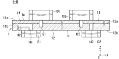
- FIG. 15 is a cross-sectional view schematically showing an example of a virtual cross section of the channel device viewed in the +Y direction at position BB.
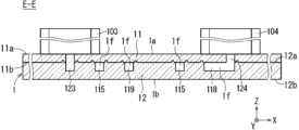
- FIG. 16 is a cross-sectional view schematically showing an example of a virtual cross section of the flow channel device viewed in the +Y direction at position EE.
- FIG. 17 is a cross-sectional view schematically showing an example of a hypothetical cross-section of the flow channel device at position CC viewed in a direction perpendicular to the +Z direction.
- FIG. 18 is a cross-sectional view schematically showing an example of a virtual cross section of the flow channel device viewed in the -X direction at position DD.
- FIG. 19 is a cross-sectional view schematically showing an example of a virtual cross section of the flow channel device viewed in the -X direction at position FF.
- FIG. 20 is a plan view schematically showing an example of a connecting member.
- FIG. 21 is a flowchart showing another first example of the processing flow in the pretreatment step.
- FIG. 22 is a plan view schematically showing an example of the state of the first flow channel device in the first stage of the pretreatment process according to the first example.
- FIG. 23 is a flowchart showing another second example of the processing flow in the pretreatment step.
- FIG. 24 is a plan view schematically showing another example of the configuration of the channel portion and the plurality of holes of the first channel device.
- FIG. 25 is a plan view schematically showing another example of the configuration of the channel portion and the plurality of holes
- Branching for separating specific types of particles (also referred to as first particles) from other types of particles (also referred to as second particles) from a liquid containing multiple types of particles (also referred to as a liquid to be treated) 2.
- a flow path device including a portion having fine flow paths also referred to as a flow path portion is known.
- the flow path section has, for example, a main flow path and a plurality of branch flow paths each narrower than the main flow path and connected to the main flow path. Then, for example, when the diameter of the first particles is larger than the diameter of the second particles, the width of each branch channel is larger than the diameter of the second particles and smaller than the diameter of the first particles. Two particles are introduced from the main channel into a plurality of branch channels and separated from the first particles flowing in the main channel.
- the resistance to the liquid flow from upstream to downstream in the main flow path is less than the resistance to liquid flow.
- the liquid to be treated is supplied upstream of a portion (also referred to as a branched portion) where a plurality of branched flow paths of the main flow path are connected, at least one It is difficult for the liquid to flow in the branched flow paths of the part, and it is easy for the liquid to flow downstream in the main flow path.
- the second particles are difficult to be introduced from the main flow path into the plurality of branch flow paths in the branched flow paths through which the liquid is difficult to flow, and the first particles and the second particles are not sufficiently separated. obtain.
- a predetermined liquid also referred to as a pretreatment liquid
- pretreatment Also called
- the resistance to the flow of the pretreatment liquid from upstream to downstream in the main flow path is such that the flow of the pretreatment liquid from upstream to downstream in each branch flow path is Less than resistance to flow.
- the pretreatment liquid is supplied upstream of the branched portion of the main channel, the presence of air makes it difficult for the pretreatment liquid to flow in the plurality of branched channels, and the pretreatment liquid is not allowed to flow downstream in the main channel. flows easily. Therefore, for example, it is not easy to fill the plurality of branch channels with the pretreatment liquid by supplying the pretreatment liquid to the main channel.
- the flow path device when the flow path device is made of a specific material such as polydimethylsiloxane (PDMS), the flow path device enclosed in the vacuum pack is taken out from the vacuum pack and then subjected to a predetermined tolerance.
- PDMS polydimethylsiloxane
- the predetermined allowable time is set to, for example, about 10 minutes to 30 minutes, and complicated work such as strict time management after opening the vacuum pack is required.
- the entire flow path device is placed in a vacuum chamber, and the inside of the vacuum chamber is depressurized by a vacuum pump to evacuate the inside of the flow path portion to a vacuum.
- a vacuum pump is connected to a part of the openings connected to the flow path in the flow path device and all remaining openings are closed, and then the inside of the flow path is evacuated by the vacuum pump.
- a mode in which vacuuming is performed to create a vacuum is also conceivable.
- a large-scale apparatus is required in a mode in which the inside of the flow channel is evacuated immediately before use of these flow channel devices. In particular, when the number of openings connected to the channel portion in the channel device is large, the size and complexity of the device and the complexity of control are caused.
- the flow path device can be easily filled with a liquid in a relatively narrow flow path in the flow path portion as a preparation prior to use for its original purpose.
- the inventors of the present disclosure have created a technology that can easily fill the relatively thin channels in the channel portion with liquid in preparation for using the channel device.
- the drawings include diagrams with a right-handed XYZ coordinate system attached for convenience.
- the +Z direction is adopted as vertically upward (also simply referred to as upward).
- the vertically downward direction is also expressed as the -Z direction.
- the direction opposite to the X direction is also expressed as the -X direction.
- a direction opposite to the Y direction is also expressed as a -Y direction.
- a part of the flow path device is omitted in each of the cross-sectional views of FIGS. 14 to 19 due to breakage.
- the "channel" has a structure through which liquid flows.
- the length of the channel in the direction orthogonal to the direction in which the channel extends is called the width of the channel.
- a relatively small width of the channel means that the channel is relatively thin, and a relatively large width of the channel means that the channel is relatively thick.
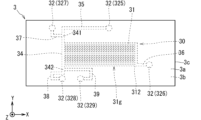
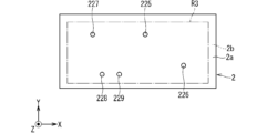
- FIG. 1 is a plan view schematically showing an example of a channel device (also referred to as a first channel device) 3 as a separation device according to the first embodiment.
- FIG. 2 is a front view schematically showing an example of the first flow channel device 3 according to the first embodiment.
- the first flow channel device 3 has, for example, a plate-like shape.
- the first flow channel device 3 includes, for example, a surface (also referred to as a first upper surface) 3a, a surface opposite to the first upper surface 3a (also referred to as a first lower surface) 3b, a first upper surface 3a and a first lower surface 3b. and a surface (also referred to as a first side surface) 3c connecting the .
- the outer surface of the first flow channel device 3 is composed of the first upper surface 3a, the first lower surface 3b, and the first side surface 3c.
- the first upper surface 3a is located on the +Z direction side of the first lower surface 3b.
- the first upper surface 3a faces the +Z direction. In other words, the first upper surface 3a has a normal along the +Z direction.
- the first lower surface 3b faces the -Z direction. In other words, the first lower surface 3b has a normal along the -Z direction.
- Each of the first upper surface 3a and the first lower surface 3b has, for example, a flat and rectangular shape.
- the thickness of the first flow path device 3 is, for example, about 1 millimeter (mm) to 5 mm.
- the thickness of the first flow channel device 3 is the length along the +Z direction of the first flow channel device 3 .
- the width of each of the first upper surface 3a and the first lower surface 3b of the first flow channel device 3 is, for example, approximately 10 mm to 50 mm.
- the width of the first upper surface 3a is the length along the +X direction of the first upper surface 3a.
- the width of the first lower surface 3b is the length along the +X direction of the first lower surface 3b.
- Each length of the first upper surface 3a and the first lower surface 3b of the first flow channel device 3 is, for example, about 10 mm to 30 mm.
- the length of the first upper surface 3a is the length along the +Y direction of the first upper surface 3a.
- the length of the first lower surface 3b is the length along the +Y direction of the first lower surface 3b.
- the first flow channel device 3 includes a flow channel portion 30 that is not open on the outer surface of the first flow channel device 3, and a flow channel portion 30 that communicates with the flow channel portion 30 and is open on the outer surface of the first flow channel device 3. and a plurality of holes 32 which are provided.
- the expression "the first part communicates with the second part” means that the first part communicates with the second part in a state in which a fluid such as a liquid can flow between the first part and the second part.
- a form in which the first part is directly connected to the part of, or a state in which a fluid can flow between the first part and the second part It means a form in which two parts are connected.
- each of the first part, the second part and the third part applies a part through which a fluid can flow, such as a channel or a hole.
- the third portion may be a portion combining two or more channels, a portion combining one or more channels and one or more holes, or a portion combining two or more channels. It may be a part in which the holes are combined.
- the channel portion 30 is located inside the first channel device 3 . From another point of view, for example, the channel portion 30 does not open to either the first upper surface 3a or the first lower surface 3b. In FIG. 2, the structure of the flow path part 30 is simplified and shown.
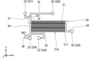
- FIG. 3 is a plan view schematically showing an example of the configuration of the channel portion 30 and the plurality of holes 32 in the first channel device 3.
- FIG. 3 the outer edge of the first flow path device 3 is omitted, and the outer edges of the flow path section 30, the two introduction holes 325, 327 and the three discharge holes 326, 328, 329 are drawn with solid lines.
- FIG. 4 shows a portion of the flow path section 30. As shown in FIG. In FIG. 4, the outer edges of the main channel 34, the plurality of branch channels 31 and the two channels 35, 37 are drawn with solid lines.
- the channel part 30 has a configuration in which a plurality of groove-shaped channels that are not open on the outer surface of the first channel device 3 are connected.
- the channel section 30 includes, for example, a channel (also referred to as a main channel) 34 as a first channel and a plurality of channels (also referred to as branch channels) 31 as a plurality of second channels.
- the main channel 34 is, for example, a linear channel extending along the -Y direction as the first direction.
- the main flow path 34 has an upstream portion (also referred to as a first upstream portion) 341 and a downstream portion (also referred to as a first downstream portion) 342 .
- the main channel 34 extends in the ⁇ Y direction as the first direction from the first upstream portion 341 toward the first downstream portion 342 .
- Each of the plurality of branch channels 31 is, for example, connected to the main channel 34 and thinner than the main channel 34 .
- each of the plurality of branch flow paths 31 has a second direction perpendicular to the -Y direction, which is the first direction between the first upstream portion 341 and the first downstream portion 342 of the main flow path 34. is opened on the side surface of +X direction.
- the main channel 34 has a plurality of portions (also referred to as connection portions) C1 to which the plurality of branch channels 31 are connected.
- each of the plurality of branch channels 31 branches off from the main channel 34 at different positions in the -Y direction as the first direction.
- the plurality of connecting portions C1 to which the plurality of branch flow paths 31 are connected are present at different positions in the -Y direction as the first direction.
- each of the plurality of branch flow paths 31 extends along the +X direction as the second direction. From another point of view, the plurality of branch channels 31 are arranged along the -Y direction as the first direction.
- the plurality of branched flow paths 31 constitute, for example, a group of branched flow paths 31 (also referred to as a branched flow path group) 31g.
- the number of the plurality of branch flow paths 31 is set, for example, from tens to hundreds. In FIGS. 1 and 3, 13 branch channels 31 are drawn for convenience.
- the plurality of holes 32 are, for example, an introduction hole 327 as a first introduction hole, an introduction hole 325 as a second introduction hole, a discharge hole 329 as a first discharge hole, and a discharge hole 326 as a second discharge hole. and a discharge hole 328 as a third discharge hole.
- the introduction hole 327 communicates with, for example, the first upstream portion 341 of the main flow path 34 .
- the introduction hole 327 is connected to the first upstream portion 341 via the channel 37 .
- the channel portion 30 includes the channel 37 as the third channel connecting the introduction hole 327 as the first introduction hole and the first upstream portion 341 .
- channel 37 is thicker than each branch channel 31 .
- the diameter of the introduction hole 327 is set equal to or greater than the width of the channel 37 .
- the portion of the channel 37 connected to the first upstream portion 341 opens on the side surface of the main channel 34 opposite to the +X direction as the second direction. In the examples of FIGS.
- the channel 37 has a portion extending from the introduction hole 327 along the ⁇ Y direction as the first direction and a portion extending along the +X direction opposite to the second direction.
- the portion connected to the first upstream portion 341 is an L-shaped flow path connected in the order of this description. In other words, the channel 37 extends in order of -Y direction and +X direction.
- the introduction hole 325 communicates with, for example, the first upstream portion 341 of the main flow path 34 .
- the introduction hole 325 is connected to the first upstream portion 341 via the channel 35 .
- the channel portion 30 includes the channel 35 as the fourth channel connecting the introduction hole 325 as the second introduction hole and the first upstream portion 341 .
- channel 35 is thicker than each branch channel 31 .
- the diameter of the introduction hole 325 is set equal to or greater than the width of the channel 35 .
- the portion of the flow path 35 connected to the first upstream portion 341 extends along the -Y direction as the first direction.
- the channel 35 is connected to the first upstream portion 341 of the main channel 34 in the -Y direction as the first direction. More specifically, for example, the channel 35 has a portion extending from the introduction hole 325 along the ⁇ X direction opposite to the second direction and a portion extending along the ⁇ Y direction as the first direction. A part is an L-shaped flow path connected in the order of this description. In other words, the channel 35 extends in the -X direction and the -Y direction in that order.
- the discharge hole 329 communicates with, for example, the first downstream portion 342 of the main flow path 34 .
- the discharge hole 329 connects to the first downstream portion 342 via the channel 39 .
- the channel portion 30 includes the channel 39 as the fifth channel connecting the discharge hole 329 as the first discharge hole and the first downstream portion 342 .
- channel 39 is thicker than each branch channel 31 .
- the diameter of the discharge hole 329 is set equal to or greater than the width of the channel 39 .
- the portion of the channel 39 connected to the first downstream portion 342 opens on the side surface of the first downstream portion 342 in the +X direction as the second direction.
- the channel 39 is connected to the first downstream portion 342 and extends along the +X direction as the second direction and in the -Y direction as the first direction.
- a U-shaped flow path is formed by connecting a portion extending in the same direction and a portion extending in the ⁇ X direction opposite to the second direction, in the order of this description.
- the channel 39 extends in order of +X direction, -Y direction and -X direction.
- the discharge hole 326 communicates with, for example, a portion (also referred to as a second downstream portion) 312 of each of the plurality of branched flow paths 31 opposite to the main flow path 34 .
- the discharge holes 326 are connected to the second downstream portions 312 of each of the plurality of branched channels 31 via the channels 36 .
- the channel portion 30 includes the channel 36 as the sixth channel connecting the discharge hole 326 as the second discharge hole and the second downstream portion 312 in each of the plurality of branched channels 31. include. More specifically, for example, each of the plurality of branch channels 31 is connected to the channel 36 at different positions in the -Y direction as the first direction. For example, channel 36 is thicker than each branch channel 31 .
- the diameter of the discharge hole 326 is set equal to or greater than the width of the channel 36 . 1 and 3, the channel 36 is connected to the plurality of second downstream portions 312 of the plurality of branched channels 31 and extends linearly along the -Y direction as the first direction.
- the portion extending linearly along the +X direction as the second direction is an L-shaped flow path connected in the order of this description.
- the channel 36 extends in the -Y direction and the +X direction in that order.
- the discharge hole 328 communicates with, for example, the first downstream portion 342 of the main flow path 34 .
- outlet 328 connects to first downstream portion 342 via channel 38 .
- the channel portion 30 includes the channel 38 as the seventh channel connecting the discharge hole 328 as the third discharge hole and the first downstream portion 342 .
- channel 38 is thicker than each branch channel 31 .
- the diameter of the discharge hole 328 is set equal to or greater than the width of the channel 38 .
- the portion of the flow path 38 connected to the first downstream portion 342 extends along the -Y direction. In the example of FIGS.
- the channel 38 is connected to the first downstream portion 342 and extends along the -Y direction as the first direction, and the part opposite to the second direction - A portion extending along the X direction, a portion extending along the -Y direction as the first direction, and a portion extending along the +X direction as the second direction and connected to the discharge hole 328.
- a part is a channel connected in the order of this description. In other words, the channel 38 extends in the -Y direction, the -X direction, the -Y direction and the +X direction in this order.
- each of the two introduction holes 325, 327 and the three discharge holes 326, 328, 329 does not open to the first upper surface 3a and opens to the first lower surface 3b.
- the introduction hole 327 has a portion (also referred to as a first introduction port or a first inlet) 1i that opens in the first lower surface 3b.
- the introduction hole 325 has a portion (also referred to as a second introduction port or a second inlet) 2i that opens in the first lower surface 3b.
- the discharge hole 329 has a portion (also referred to as a first discharge port or a first outlet) 1o that opens in the first lower surface 3b.
- the discharge hole 326 has a portion (also referred to as a second discharge port or a second outlet) 2o that opens in the first lower surface 3b.
- the discharge hole 328 has a portion (also referred to as a third discharge port or a third outlet) 3o that opens in the first lower surface 3b.
- a liquid containing a plurality of types of particles P100 and P200 (see FIG. 4) (also referred to as liquid to be treated) is introduced into the first flow path device 3 .
- the first flow path device 3 separates the separation target particles P100, which are particles of a specific kind, from particles of other kinds (also referred to as particles of other kinds) P200 and discharges them.
- Plural types of particles may be three or more types.
- each of the separation target particles P100 and the other-type particles P200 is a particle of one type is exemplified.
- the pressing liquid is introduced into the first channel device 3 from the introduction hole 327 .
- the liquid to be treated is introduced into the first flow channel device 3 through the introduction hole 325 . Specific examples and functions of the pressing liquid will be described later.
- a pipe for supplying the pressing liquid is connected to the first flow path device 3 from the outside of the first flow path device 3. obtain.
- the first lower surface 3b of the first flow path device 3 is introduced in a plan view (hereinafter, unless otherwise specified, a plan view in the -Z direction).
- the introduction hole 325 When the liquid to be treated is introduced from the introduction hole 325 into the first flow path device 3, for example, a pipe for supplying the liquid to be treated is connected to the first flow path device 3 from the outside of the first flow path device 3. obtain.
- this pipe for example, on the first lower surface 3b of the first flow path device 3, when viewed from above, the introduction hole 325 is positioned in a state surrounding the Z axis, and in the +Z direction. There may be a protruding tubular portion.
- the liquid to be treated introduced into the first channel device 3 through the introduction hole 325 flows into the first upstream portion 341 of the main channel 34 via the channel 35 .
- the pressing liquid introduced into the first channel device 3 through the introduction hole 327 flows through the channel 37 into the first upstream portion 341 of the main channel 34 .
- An arrow Fp1 drawn with a two-dot chain line in FIG. 4 indicates the direction in which the pressing liquid is directed. This direction is along the +X direction.
- An arrow Fm1 drawn by a two-dot chain line thicker than the arrow Fp1 in FIG. 4 indicates the direction in which the main flow (also referred to as the main flow) of the liquid to be treated flowing through the main flow path 34 from the flow path 35 heads. The direction in which this main flow is directed is the direction along the -Y direction as the first direction.
- a rectangle drawn with a thin two-dot chain line in FIG. 4 virtually indicates the outer edge of the first upstream portion 341 .
- FIG. 4 schematically shows how the particles P100 to be separated are separated from each other when the diameter of the particles P100 to be separated is larger than the diameter of the other-type particles P200.
- the width of each branch channel 31 is larger than the diameter of the other-type particles P200 and smaller than the diameter of the separation target particles P100.
- the width of the branch channel 31 is the length of the branch channel 31 along the Y direction.
- each of the main channel 34 and the channel 35 is larger than the diameter of each of the separation target particles P100 and the other-type particles P200.
- the width of the main channel 34 is the length of the main channel 34 along the X direction perpendicular to the -Y direction as the first direction.
- the width of the channel 35 is the length of the channel 35 along the X direction in the vicinity of the main channel 34 .
- the width of the channel 35 is the length of the channel 35 along the Y direction at the position where the channel 35 extends along the -X direction.
- Most of the other-species particles P200 are introduced into any one of the plurality of branched flow paths 31 by being pushed in the +X direction while moving in the -Y direction as the first direction in the main flow path 34. . Most of the other-species particles P200 are discharged to the outside of the first flow channel device 3 from the discharge holes 326 via any one of the plurality of branch flow channels 31 and further through the flow channel 36 .
- the particles of other species P200 are introduced from the main flow channel 34 into any of the plurality of branch flow channels 31 and separated. It is separated from the target particle P100.
- the other-species particles P200 discharged from the discharge hole 326 to the outside of the first flow path device 3 are, for example, subjected to a specific treatment in another device connected directly to the discharge hole 326 or via another member such as a pipe. may be provided to or may simply be collected.
- the other-species particles P200 discharged from the discharge hole 326 to the outside of the first channel device 3 may be discarded, for example, directly or via another member such as a pipe.
- the separation target particles P100 are hardly introduced into the plurality of branch channels 31 and move in the main channel 34 in the -Y direction as the first direction. Most of the particles P100 to be separated pass through the main channel 34 and further through the channel 39 and are discharged from the discharge hole 329 to the outside of the first channel device 3 .
- the width of the channel 39 is larger than the separation target particles P100.
- the separation target particles P100 that have reached the first downstream portion 342 enter the flow path 39 instead of the flow path 38 by the same action as the other-type particles P200 introduced into any of the plurality of branch flow paths 31 in the main flow path 34. influx.
- the particles to be separated P100 discharged from the discharge hole 329 to the outside of the first channel device 3 are subjected to a specific treatment in another device connected directly to the discharge hole 329 or via another member such as a pipe, for example. may be provided to or may simply be collected.
- the composition (also referred to as the residual composition) of the liquid to be treated excluding the other-species particles P200 flowing to any of the plurality of branched flow paths 31 and the separation-target particles P100 flowing to the flow path 39 flows into the flow path 38. influx.
- This residual composition passes through channel 38 and is discharged from discharge hole 328 .
- the remaining composition discharged from the discharge hole 328 to the outside of the first channel device 3 is, for example, in another device connected directly to the discharge hole 328 or via another member such as a pipe, It may be subjected to a specific treatment or simply recovered.
- the remaining composition discharged from the discharge hole 328 to the outside of the first channel device 3 may be discarded, for example, directly or via another member such as a pipe.
- a flow that introduces the liquid to be treated into the branch channel 31 (also referred to as an introduction flow) is used.
- the introduced flow can contribute to the separation of the separation target particles P100 and the other-type particles P200 by the main channel 34 and the plurality of branch channels 31 .
- the inflow is indicated in FIG. 4 by the hatched region Ar1 using sand.
- the state of the introduced flow indicated by the area Ar1 in FIG. 4 is merely an example, and the flow velocity and flow rate of the liquid to be treated introduced from the flow channel 35 to the main flow channel 34 and the flow rate from the flow channel 37 to the main flow channel 34 are shown. It can change according to the flow velocity and flow rate of the pressing liquid introduced into the first upstream portion 341 .
- the pressing liquid presses the liquid to be processed against the plurality of branched flow paths 31 in the +X direction from the side opposite to the plurality of branched flow paths 31 .
- the pressing liquid can contribute to the generation of the inductive flow.
- the main flow path 34 extends in the -Y direction as the first direction.
- a portion of the channel 35 connected to the first upstream portion 341 of the main channel 34 extends along the -Y direction as the first direction.
- Each of the plurality of branch channels 31 is open on the side surface in the +X direction as the second direction between the first upstream portion 341 and the first downstream portion 342 of the main channel 34 .
- the flow path 37 is opened on the side surface of the first upstream portion 341 of the main flow path 34 in the ⁇ X direction opposite to the second direction.
- the liquid to be processed containing a plurality of types of particles is supplied to the main flow path 34 via the introduction hole 325 .
- a liquid flow can be generated at 34 that forces particles of multiple species toward multiple branch channels 31 .
- the other-type particles P ⁇ b>200 which are particles having a diameter smaller than the width of each branch flow channel 31 among the plurality of types of particles, easily flow into the plurality of branch flow channels 31 .
- separation target particles P100 which are particles with a diameter larger than the width of each branch channel 31, and particles with a diameter smaller than the width of each branch channel 31 can be easily separated from the other kind of particles P200.
- the portion of the channel 39 connected to the first downstream portion 342 of the main channel 34 is in the +X direction as the second direction of the first downstream portion 342. It is open on the sides. For this reason, for example, the action of the introduction flow in the main channel 34 facilitates the separation target particles P ⁇ b>100 having a larger diameter than the width of each branch channel 31 to flow into the channel 39 . Thereby, for example, the separation target particles P100 can be easily discharged from the discharge hole 329 to the outside of the first flow path device 3 through the flow path 39 .
- separation target particles P100 which are particles with a diameter larger than the width of each branch channel 31, and particles with a diameter smaller than the width of each branch channel 31 can be easily separated from the other kind of particles P200.
- the width of the flow introduced into the main channel 34 is shown as the width W1 in the vicinity of the region where the main channel 34 branches into the plurality of branch channels 31 .
- the width of the introduced flow in the main channel 34 is the length of the introduced flow along the X direction.
- the width W1 can be set, for example, by adjusting the cross-sectional areas and lengths of the main channel 34 and the plurality of branch channels 31 and by adjusting the flow rates of the liquid to be treated and the pressing liquid.
- the width W1 is exemplified by a width that does not include the center of gravity of the separation target particles P100 but includes the center of gravity of the other-type particles P200 in the region Ar1 of the introductory flow.
- Blood which is a liquid containing multiple types of particles, is used as an example of the liquid to be processed.
- the particles P100 to be separated are white blood cells and the other-species particles P200 are red blood cells. Measurement of the number of white blood cells is employed as an example of specific processing for the separation target particles P100.
- Plasma or the like is adopted as an example of the residual composition that flows through the channel 38 and is discharged from the first channel device 3 through the discharge hole 328 .
- phosphate-buffered saline (PBS) is employed as an example of the pressing liquid.
- a liquid obtained by adding other components to PBS may be applied as the pressing liquid.
- other components for example, ethylenediaminetetraacetic acid (EDTA) may be applied as the second component, and bovine serum albumin (BSA) may be applied as the third component. good.
- EDTA ethylenediaminetetraacetic acid
- BSA bovine serum albumin
- the position of the center of gravity of red blood cells is, for example, about 2 micrometers ( ⁇ m) to 2.5 ⁇ m from the outer edge of red blood cells.
- the maximum diameter of red blood cells is, for example, about 6 ⁇ m to 8 ⁇ m.
- the centroid position of the leukocyte is, for example, a position about 5 ⁇ m to 10 ⁇ m from the outer edge of the leukocyte.
- the maximum diameter of white blood cells is, for example, about 10 ⁇ m to 30 ⁇ m. From the viewpoint of separating erythrocytes and leukocytes in the blood, a value of about 2 ⁇ m to 15 ⁇ m is adopted as the width W1 of the introduced flow.
- the cross-sectional area of the virtual cross section along the XZ plane of the main channel 34 is, for example, about 300 square micrometers ( ⁇ m 2 ) to 1000 ⁇ m 2 .
- the length of the main channel 34 along the Y direction is, for example, about 0.5 mm to 20 mm.
- a cross-sectional area of a virtual cross section along the YZ plane of the branch flow path 31 is, for example, about 100 ⁇ m 2 to 500 ⁇ m 2 .
- the length of the branch channel 31 along the X direction is, for example, about 3 mm to 25 mm.
- the flow velocity of the liquid to be treated flowing in the -Y direction as the first direction in the main channel 34 is, for example, about 0.2 meters per second (m/s) to 5 m/s.
- the flow rate of the liquid per unit time in the main channel 34 is, for example, about 0.1 microliters per second ( ⁇ l/s) to 5 ⁇ l/s.
- the total volume of the flow path section 30, the two introduction holes 325, 327 and the three discharge holes 326, 328, 329 is reduced from 0.5 microliters ( ⁇ l) to about 2 ⁇ l.
- the total volume of the main channel 34, the two channels 35, 37 and the two introduction holes 325, 327 can be set to about 0.07 ⁇ l to 0.3 ⁇ l.
- the total volume of the main flow path 34, the four flow paths 35, 37, 38, 39, the two introduction holes 325, 327 and the two discharge holes 328, 329 is set to about 0.1 ⁇ l to 0.5 ⁇ l. obtain.
- PDMS has excellent transferability when performing resin molding using a mold.
- the transferability is a property of forming fine unevenness corresponding to a fine pattern of a mold in a resin molded article.
- the first flow path device 3 includes, for example, a plate-like first portion having, on one side, fine unevenness corresponding to the pattern of the flow path section 30, two introduction holes 325 and 327 and three discharge holes 326, 328, It can be manufactured by joining a plate-like second portion having five through holes corresponding to 329 in such a manner that one side of the second portion covers the fine unevenness of the first portion.
- the first portion having fine unevenness on one side can be produced, for example, by resin molding.
- the second portion having five through-holes may be produced, for example, by resin molding, or may be produced by forming five through-holes in a plate-like member formed by resin molding by punching or the like. good too.
- the bonding of the first part and the second part is achieved, for example, by surface modification to one side of the first part and one side of the second part, and contacting one side of the first part with one side of the second part, using an adhesive.
- can be realized without Surface modification is achieved by, for example, irradiation with oxygen plasma or irradiation with ultraviolet (UV) light using an excimer lamp.
- UV ultraviolet
- one side of the first portion and one side of the second portion are made of the same kind of resin, the bonding strength between the one side of the first portion and the one side of the second portion using surface modification is improved. obtain.
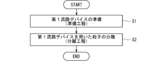
- FIG. 5 is a flowchart showing an example of the flow of processing for separating particles using the first channel device 3. As shown in FIG.
- a step of preparing the first channel device 3 (also referred to as a preparation step) in step S1 and separation of particles using the first channel device 3 in step S2 are performed.
- the steps (also referred to as separation steps) are performed in the order described.
- the preparation process is a process for preparing the first flow path device 3 in advance in order to perform the separation process.
- a process of introducing the liquid (also referred to as pretreatment liquid) into the channel section 30 (also referred to as an introduction process) is performed.
- This introduction process is a process for washing the first channel device 3 and realizing a smooth flow of the liquid to be treated in the channel section 30 (particularly the narrow branch channels 31) in the separation step.
- the pretreatment liquid is also used as the pressing liquid.
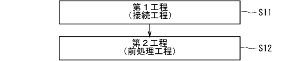
- FIG. 6 is a flowchart showing an example of the flow of processing in the preparation process performed in step S1 of FIG.
- a connecting process as a first process in step S11 and a pretreatment process as a second process in step S12 are performed in this order.
- the method for preparing the first flow path device 3 has a connecting step as a first step and a pretreatment step as a second step.
- FIG. 7 is a flow chart showing an example of the flow of processing in the pretreatment step of step S12 of FIG.
- FIG. 8 is an image diagram showing an example of the connection state of each part in the connection process.
- the first liquid supply unit 4 for supplying the pretreatment liquid to the main flow path 34 through the introduction hole 327 is connected to the introduction hole 327, and the plurality of branch flow paths 31 and A liquid suction unit 5 for sucking the pretreatment liquid through the discharge hole 326 is connected to the discharge hole 326 .
- the first liquid supply section 4 is connected to the introduction hole 327 via a pipe 4c or the like.
- a connector for connecting to the introduction hole 327 As shown in FIG.
- the liquid suction part 5 is connected to the discharge hole 326 via a tube 5c or the like.
- each pipe 4c, 5c is drawn with a thin two-dot chain line for convenience, and the direction in which the pretreatment liquid flows in each pipe 4c, 5c is indicated by an arrow drawn with a thin two-dot chain line.
- the introduction hole 325 may be connected to the second liquid supply section 6 for supplying the liquid to be treated to the main flow path 34 via the introduction hole 325 .
- the second liquid supply section 6 is connected to the introduction hole 325 via a pipe 6c or the like.
- a connector for connecting to the introduction hole 325.
- the second liquid supply unit 6 and the pipe 6c are drawn with a thin two-dot chain line for convenience, and the direction in which the liquid to be treated flows in the pipe 6c is indicated by an arrow drawn with a thin two-dot chain line.
- the discharge hole 329 may be connected directly or via another member such as a pipe to a device for performing a specific treatment on the particles P100 to be separated or recovering the particles P100 to be separated.
- vent 328 may have a device directly or otherwise, such as a tube, to perform specific treatment or recovery of the residual composition discharged from vent 328. You may connect through a member.
- a mechanism capable of supplying the pretreatment liquid using a pump such as a syringe pump or a flanger pump, for example, is applied to the first liquid supply unit 4 .
- the operation of the first liquid supply section 4 can be controlled according to a signal from the control section 7, for example.
- the control unit 7, for example starts and stops the supply of the pretreatment liquid toward the main flow path 34 by the first liquid supply unit 4, and causes the first liquid supply unit 4 to supply the pretreatment liquid toward the main flow
- the supply amount of the treatment liquid per unit time (also referred to as the first supply rate) can be controlled.
- a mechanism capable of sucking liquid and gas using a pump such as a diaphragm pump or a syringe pump is applied to the liquid suction unit 5 .
- the gas sucked by the pump exists mainly in the channel 37 , the main channel 34 , the branch channel 31 and the channel 36 before the pretreatment liquid reaches the discharge hole 326 .
- This gas needs to be sucked out before the pretreatment liquid reaches the drain hole 326 and begins directly pumping the pretreatment liquid.
- the expression “liquid suction” includes sucking gas present in a flow path as a step prior to directly sucking liquid using a pump.
- the operation of the liquid suction section 5 can be controlled according to a signal from the control section 7, for example.
- control unit 7 controls, for example, the start and stop of suction of the pretreatment liquid from the main flow channel 34 by the liquid suction unit 5 via the plurality of branch flow channels 31, the flow channel 36 and the discharge hole 326, and the liquid It is possible to control the amount of pretreatment liquid sucked per unit time (also referred to as first suction speed) from the main channel 34 by the suction unit 5 via the plurality of branch channels 31 , channels 36 and discharge holes 326 .
- a mechanism capable of supplying the liquid to be treated using a pump such as a syringe pump or a flanger pump, for example, is applied to the second liquid supply section 6 .
- the operation of the second liquid supply section 6 can be controlled according to a signal from the control section 7, for example.
- the control unit 7 controls, for example, the start and stop of the supply of the liquid to be treated toward the main flow path 34 by the second liquid supply unit 6 and the The supply amount of the treatment liquid per unit time (also referred to as a second supply rate) can be controlled.
- the control unit 7 can control the operations of elements such as the first liquid supply unit 4, the liquid suction unit 5, and the second liquid supply unit 6, for example.
- the control unit 7 may be, for example, a computer or the like, or may be a control circuit.
- Control unit 7 includes at least one processor to provide control and processing power to perform various functions, as described in further detail below.
- At least one processor may be implemented in a single integrated circuit (IC), or multiple ICs and/or discrete circuits communicatively coupled. At least one processor may be implemented according to various known techniques.
- a processor includes one or more circuits or units configured in a manner to perform one or more data computing procedures or processes, such as by executing instructions stored in associated memory.
- the processor may be firmware (eg, discrete logic components) configured in a form to perform one or more data computing procedures or processes.
- the processor is one or more of processors, controllers, microprocessors, microcontrollers, Application Specific Integrated Circuits (ASICs), digital signal processors, programmable logic devices, field programmable A gate array, or any combination of these devices or configurations, or other known combinations of devices and configurations, may be included to perform the functions described below.
- ASICs Application Specific Integrated Circuits
- digital signal processors programmable logic devices, field programmable A gate array, or any combination of these devices or configurations, or other known combinations of devices and configurations, may be included to perform the functions described below.
- control unit 7 includes a CPU (Central Processing Unit) 71 and a storage unit 72, for example.
- the storage unit 72 includes non-temporary recording media readable by the CPU 71, such as ROM (Read Only Memory) and RAM (Random Access Memory).
- the storage unit 72 stores a program P1 and the like for controlling the first liquid supply unit 4, the liquid suction unit 5, the second liquid supply unit 6, and the like.
- Various functions of the control unit 7 are realized by the CPU 71 executing the program P1 in the storage unit 72 .
- control unit 7 may include multiple CPUs 71 .
- control unit 7 may include at least one DSP (Digital Signal Processor).
- DSP Digital Signal Processor
- all functions of the control unit 7 or some functions of the control unit 7 may be realized by a hardware circuit that does not require software for realizing the functions.
- the storage unit 72 may also include a non-temporary computer-readable recording medium other than ROM and RAM.
- the storage unit 72 may include, for example, a small hard disk drive and/or SSD (Solid State Drive).
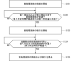
- steps S121 to S125 are performed in the order described.
- This pretreatment step can be realized, for example, by controlling the first liquid supply section 4 and the liquid suction section 5 by the control section 7 .
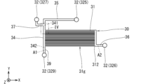
- FIGS. 9 to 11 are diagrams schematically showing an example of changes in the state of introduction of the pretreatment liquid into the first flow channel device 3 in the pretreatment step.
- FIG. 9 is a plan view schematically showing an example of the state of the first flow channel device 3 before starting the pretreatment process.
- FIG. 10 is a plan view schematically showing an example of the state of the first flow channel device 3 in the first stage of the pretreatment process.
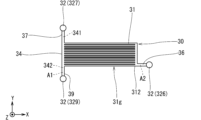
- FIG. 11 is a plan view schematically showing an example of the state of the first flow channel device 3 in the second stage of the pretreatment process.
- the area where the pretreatment liquid is present is indicated by hatching with slanted lines rising to the right.
- FIGS. 10 and 11 the direction in which the pretreatment liquid flows is indicated by thin double-dashed arrows.
- step S121 an operation (also referred to as a supply operation) of supplying the pretreatment liquid to the main channel 34 via the introduction hole 327 by the first liquid supply unit 4 is started.
- the pretreatment liquid is supplied from the introduction hole 327 to the main flow path 34 via the flow path 37 .
- the pretreatment liquid is supplied toward the main flow path 34 through the introduction hole 327 by the first liquid supply section 4 at the first supply speed.
- the first supply rate is set, for example, from 100 microliters per minute ( ⁇ l/min) to 400 ⁇ l/min.
- the first supply rate may, for example, be constant or slightly fluctuate over time.
- each branch channel 31 of the channel section 30 has a smaller width than the other channels, and the presence of air in each branch channel 31 makes it difficult for the pretreatment liquid to flow. . Therefore, as shown in FIG. 10, the pretreatment liquid supplied from the introduction hole 327 to the main flow path 34 via the flow path 37 flows toward the introduction hole 325 via the flow path 35 and flows toward the main flow path 325 . Flow occurs through channel 34 and channel 39 in sequence to discharge hole 329 and through main channel 34 and channel 38 in sequence to discharge hole 328 .
- step S122 it is determined whether or not the pretreatment liquid has reached the discharge holes 329 and 328. This determination is made, for example, by the control unit 7 as to whether or not the first predetermined time has passed since the supply operation by the first liquid supply unit 4 was started, or whether the first liquid supply unit 4 has started the supply operation. This can be achieved by determining whether or not the amount of pretreatment liquid supplied by the supply unit 4 has reached the first predetermined amount.
- the first predetermined time and the first predetermined amount can be set, for example, according to the results of experiments using the first flow path device 3 or simulations related to the first flow path device 3 .
- step S ⁇ b>122 is repeated until the pretreatment liquid reaches the discharge holes 329 and 328 .
- the determination in step S122 is repeated until the supply amount reaches the first predetermined amount.
- step S123 the process proceeds to step S123.
- the first predetermined time has elapsed since the start of the supply operation by the first liquid supply unit 4, or the pretreatment liquid by the first liquid supply unit 4 has elapsed since the start of the supply operation by the first liquid supply unit 4. If the supply amount reaches the first predetermined amount, the process proceeds to step S123. At this time, an area (also referred to as a first area) A1 from the introduction hole 327 to the two discharge holes 328 and 329 via the main flow path 34 is filled with the pretreatment liquid.
- two discharge holes 328 and 329 may be included in the first area A1.
- the first area A1 when the first area A1 is filled with the pretreatment liquid, air bubbles or air exist to such an extent that the pretreatment liquid is not divided in each channel and each hole 32 of the first area A1. state.
- the state in which the first area A1 is filled with the pretreatment liquid is the flow paths and the introduction holes of the first area A1. It may include a state in which air bubbles or air exist to the extent that the pretreatment liquid is not split at 327 .
- step S123 the liquid suction unit 5 starts an operation (also referred to as a suction operation) for sucking the pretreatment liquid from the main flow path 34 through the plurality of branch flow paths 31 and the discharge holes 326 .
- the suction operation is started after the pretreatment liquid is supplied from the introduction hole 327 to the discharge holes 328 and 329 through the main flow path 34 by the first liquid supply unit 4 .
- the liquid suction unit 5 sucks the pretreatment liquid from the main channel 34 through the plurality of branch channels 31 and the discharge holes 326 at the first suction speed.
- the first suction speed is set to be less than or equal to the first supply speed.
- the liquid suction section 5 supplies a plurality of branch flows from the main flow path 34 .
- the pretreatment liquid is sucked through the channel 31 and the discharge hole 326 at a first suction speed that is less than or equal to the first supply speed.
- the first suction speed is set, for example, from 50 ⁇ l/min to 200 ⁇ l/min.
- the first suction speed for example, may be constant over time, or may vary slightly.
- each branch flow path 31 has a smaller width than the other flow paths
- the pretreatment liquid is forcibly flowed in each branch flow path 31 by the suction operation of the liquid suction section 5. .
- the pretreatment liquid flows from the main channel 34 toward the discharge hole 326 through the plurality of branch channels 31 and the channels 36 in order.
- the area from the main flow path 34 to the discharge hole 326 via the plurality of branch flow paths 31 can be filled with pretreatment liquid.
- the discharge hole 326 may be included in the second area A2.
- the pretreatment liquid when the second area A2 is filled with the pretreatment liquid, bubbles or air exist to such an extent that the pretreatment liquid is not divided in each channel and the discharge hole 326 of the second area A2. state.
- the pretreatment liquid when the second area A2 does not include the discharge hole 326, the pretreatment liquid is not divided in each channel of the second area A2 when the second area A2 is filled with the pretreatment liquid. It may include the presence of air bubbles or air to some extent.
- the suction operation by the liquid suction section 5 is started.
- the pretreatment liquid is discharged from the main flow path 34 via the plurality of branch flow paths 31, respectively.
- step S ⁇ b>124 it is determined whether or not the pretreatment liquid has filled the flow path section 30 and reached all the holes 32 of the first flow path device 3 .
- This determination is realized, for example, by the control unit 7 determining whether or not the second predetermined time has elapsed from the start of the suction operation by the liquid suction unit 5 or the start of the supply operation by the first liquid supply unit 4. obtain.
- the second predetermined time can be set, for example, according to the results of experiments using the first flow path device 3 or simulations related to the first flow path device 3 .
- the state in which the flow path section 30 is filled with the pretreatment liquid may include, for example, a state in which bubbles or air exist in each flow path of the flow path section 30 to such an extent that the pretreatment liquid is not divided.
- step S ⁇ b>124 is repeated until the pretreatment liquid fills the flow path part 30 and reaches all the holes 32 of the first flow path device 3 .
- the determination in step S124 is repeated until the second predetermined time elapses from the start of the suction operation by the liquid suction unit 5 or the start of the supply operation by the first liquid supply unit 4 .
- step S125 when the pretreatment liquid fills the channel portion 30 and reaches all the holes 32 of the first channel device 3, the process proceeds to step S125.
- the process proceeds to step S125.
- a first area A1 extending from the introduction hole 327 to the two discharge holes 328 and 329 via the main flow path 34, and a second area A2 extending from the main flow path 34 to the discharge hole 326 via the plurality of branch flow paths 31, respectively. is filled with pretreatment liquid.
- step S125 the supply operation by the first liquid supply unit 4 and the suction operation by the liquid suction unit 5 are stopped.
- the liquid to be treated is introduced through the introduction hole 325 and the pressing liquid is introduced through the introduction hole 327 into the flow path section 30 of the first flow path device 3 .
- the liquid to be treated is supplied by the second liquid supply section 6 to the first upstream portion 341 of the main flow path 34 through the introduction hole 325 and the flow path 35 in order.
- the pressing liquid is supplied by the first liquid supply section 4 to the first upstream portion 341 of the main flow path 34 through the introduction hole 327 and the flow path 37 in this order.
- the other type of particles P200 among the plurality of types of particles contained in the liquid to be treated are introduced from the main flow path 34 into any of the plurality of branch flow paths 31. It is separated from the separation target particles P100. Particles to be separated P100 among the plurality of types of particles contained in the liquid to be treated are hardly introduced into the plurality of branched flow paths 31, but pass through the main flow path 34 and further through the flow path 39. It is discharged from the discharge hole 329 to the outside of the first channel device 3 .
- the method for preparing the first flow channel device 3 according to the first embodiment includes a connecting step as a first step and a pretreatment step as a second step.
- the first liquid supply unit 4 for supplying the pretreatment liquid to the main flow path 34 through the introduction hole 327 is connected to the introduction hole 327 , and the plurality of branch flow paths 31 and the discharge holes 326 are connected from the main flow path 34 .
- the liquid suction part 5 for sucking the pretreatment liquid is connected to the discharge hole 326 through the .
- the liquid suction unit 5 causes a plurality of branch flows from the main flow path 34.
- the pretreatment liquid is sucked through the channel 31 and the discharge hole 326 at a first suction speed that is less than or equal to the first supply speed.
- each branch flow path 31 has a smaller width than the other flow paths, the pretreatment liquid is forcibly flowed in each branch flow path 31 by the suction operation of the liquid suction section 5. .
- a first area A1 extending from the introduction hole 327 to the two discharge holes 328 and 329 via the main flow path 34, and a second area A2 extending from the main flow path 34 to the discharge hole 326 via the plurality of branch flow paths 31 respectively. Can be filled with pretreatment liquid.
- the preparation method of the first flow channel device 3 for example, from the main flow channel 34 through the plurality of branch flow channels 31 narrower than the other flow channels in the flow channel section 30 and the discharge holes 326 .
- a simple configuration is adopted in which the liquid suction part 5 for sucking the pretreatment liquid is connected to the discharge hole 326 .
- the relatively thin branch channels 31 in the channel portion 30 of the first channel device 3 can be quickly filled with the pretreatment liquid by the liquid suction portion 5 such as a pump connected to the discharge hole 326. can.
- a vacuum pump is connected to the openings of some of the holes and the remaining There is no need for a large-scale device or complicated control for vacuuming the inside of the channel section 30 with a vacuum pump in a state in which all the openings of the holes are blocked.
- each relatively narrow branch channel 31 in the channel portion 30 of the first channel device 3 can be easily filled with the pretreatment liquid.
- the first flow channel device 3 as the separation device according to the first embodiment is combined with the flow channel device (also referred to as the second flow channel device) 1 as the processing device to form a type of flow channel device.
- separation processing device 100 may be configured.
- FIG. 12 is a plan view showing an example of the separation processing device 100 according to the second embodiment.
- the separation processing device 100 includes, for example, a first channel device 3, a connection member 2, and a second channel device 1.
- the second flow channel device 1, the connection member 2, and the first flow channel device 3 are in a state of being stacked one on top of the other in the +Z direction in this order.
- the connection member 2 is positioned on the second flow path device 1 and the first flow path device 3 is positioned on the connection member 2 .
- the second flow path device 1 has a surface (also referred to as a second upper surface) 1a and a surface (also referred to as a second lower surface) 1b.
- the second upper surface 1a is located on the +Z direction side of the second lower surface 1b.
- the connection member 2 has a surface (also referred to as a third upper surface) 2a and a surface (also referred to as a third lower surface) 2b.
- the third upper surface 2a is located on the +Z direction side of the third lower surface 2b.
- the third lower surface 2b is in contact with the second upper surface 1a of the second flow path device 1.
- the third upper surface 2 a is in contact with the first lower surface 3 b of the first channel device 3 .
- the connection member 2 is interposed between the first lower surface 3b of the first channel device 3 and the second upper surface 1a of the second channel device 1.
- the third lower surface 2b and the second upper surface 1a are bonded by plasma bonding, optical bonding, or the like, for example.
- the first lower surface 3b and the third upper surface 2a are bonded by plasma bonding, optical bonding, or the like, for example.
- Oxygen plasma for example, is used for the plasma bonding described above.
- Ultraviolet light from, for example, an excimer lamp is used for the above optical bonding.
- the second flow path device 1 and the connection member 2 have, for example, a plate-like outer shape that is rectangular in plan view, similar to the first flow path device 3 .
- the second upper surface 1a, the second lower surface 1b, the third upper surface 2a and the third lower surface 2b are perpendicular to the +Z direction, like the first upper surface 3a and the first lower surface 3b.
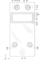
- FIG. 13 is a plan view schematically showing an example of the second channel device 1.
- a region R2 surrounded by a rectangular dashed line indicates a position where the third lower surface 2b of the connecting member 2 is joined on the second upper surface 1a.
- the second flow channel device 1 for example, a region of the second upper surface 1a other than the region R2, the second lower surface 1b, and the side surface connecting the second upper surface 1a and the second lower surface 1b are used for separation processing. It constitutes the outer surface of the device 100 .
- the thickness of the second flow path device 1 is, for example, about 0.5 mm to 5 mm.
- the thickness of the second flow path device 1 is the length of the second flow path device 1 along the +Z direction.
- Each width of the second upper surface 1a and the second lower surface 1b is, for example, about 10 mm to 50 mm.
- the width of the second upper surface 1a is the length along the +X direction of the second upper surface 1a.
- the width of the second lower surface 1b is the length along the +X direction of the second lower surface 1b.
- Each length of the second upper surface 1a and the second lower surface 1b is, for example, about 20 mm to 100 mm.
- the length of the second upper surface 1a is the length along the +Y direction of the second upper surface 1a.
- the length of the second lower surface 1b is the length along the +Y direction of the second lower surface 1b.
- the second channel device 1 has, for example, six introduction holes 121, 122, 124, 126, 128, 129, two discharge holes 125, 127 and a stirring hole 123.
- Each of the three introduction holes 126, 128, 129 and the two discharge holes 125, 127 opens at the second upper surface 1a in the region R2.
- Each of the three introduction holes 121, 122, 124 and the stirring hole 123 opens on the second upper surface 1a at positions other than the region R2. In other words, none of the six introduction holes 121, 122, 124, 126, 128, 129, the two discharge holes 125, 127 and the stirring hole 123 are open on the second lower surface 1b.
- the second channel device 1 has three discharge holes 141, 142, 143, for example.
- Each of the three discharge holes 141, 142, 143 is open on the second lower surface 1b at positions other than the region R2. In other words, none of the discharge holes 141, 142, 143 are open on the second upper surface 1a.
- the second channel device 1 has, for example, a plurality of channels 1f.
- the multiple channels 1f include, for example, a stirring channel 115, eight channels 111, 112, 113, 114, 116, 117, 118, 119, a measurement channel 151 and a reference channel 152.
- Each of the plurality of flow paths 1f is a groove-shaped flow path that opens to neither the second upper surface 1a nor the second lower surface 1b.
- the channel 111 communicates with the introduction hole 121 and the discharge hole 127.
- Channel 112 communicates with inlet hole 128 and outlet hole 141 .
- Channel 113 communicates with inlet hole 122 and outlet hole 125 .
- Channel 114 communicates with inlet hole 126 and outlet hole 142 .
- the measurement channel 151 is a channel interposed between the channel 117 and the channel 119 .
- the measurement channel 151 has a direction in which the measurement channel 151 extends (also referred to as a first longitudinal direction).
- the first longitudinal direction is the direction along the ⁇ Y direction from channel 117 to channel 119 .
- the measurement channel 151 extends in the -Y direction.
- the measurement channel 151 is connected to the channel 117 at the end on the +Y direction side, and is connected to the channel 119 at the end on the side opposite to the +Y direction ( ⁇ Y direction side). A portion where the measurement channel 151 is connected to the channel 117 overlaps with the region R2 in plan view.
- the measurement flow path 151 has an area (also referred to as a first end area) E1 positioned at one end in the first longitudinal direction and an area opposite to the first end area E1 in the first longitudinal direction. and a region (also referred to as a second end region) E2 located at the end of the .
- the measurement channel 151 has a first end region E1 and a second end region E2 on both sides in the first longitudinal direction.
- the first end region E1 is located at the end of the measurement channel 151 on the +Y direction side
- the second end region E2 is located at the ⁇ It is located at the end on the Y-direction side.
- the introduction hole 129 is connected to the first end region E1 of the measurement channel 151 . Therefore, the introduction hole 129 is a hole that is connected to the measurement channel 151 and opens to the second upper surface 1a.
- the measurement channel 151 is connected to the channel 117 in the first end region E1.
- the first end region E1 of the measurement channel 151 is connected to the stirring channel 115 via part of the channels 117 and 116 .
- the expression "the first part is connected to the second part” means that the first part is connected to the second part in a state in which fluid can flow between the first part and the second part. directly connected, or in which the first portion is connected to the second portion via another portion (the third portion) such that fluid can flow between the first portion and the second portion; means the form in which Therefore, the stirring channel 115 communicates with the first end region E ⁇ b>1 of the measurement channel 151 .
- the channel 116 is interposed between the channel 117 and the reference channel 152 and connected to the stirring channel 115 between the channel 117 and the reference channel 152 .
- Channel 117 is interposed between measurement channel 151 and channel 116 .
- Channel 118 is connected to inlet 124 and intervenes between inlet 124 and reference channel 152 .
- the channel 119 is interposed between the discharge hole 143 and the measurement channel 151 and connected to the discharge hole 143 . Therefore, the discharge hole 143 is a hole that is connected to the measurement flow path 151 via the flow path 119 and opens to the second lower surface 1b. More specifically, the discharge hole 143 is connected to the second end region E2 of the measurement channel 151 via the channel 119 .
- the stirring channel 115 is a channel interposed between the stirring hole 123 and the channel 116 .
- the stirring channel 115 has a direction in which the stirring channel 115 extends (also referred to as a second longitudinal direction).
- the stirring flow path 115 meanders. Specifically, from the stirring hole 123 toward the channel 116, the stirring channel 115 is formed in the order along the +Y direction, the +X direction, the ⁇ Y direction, the +X direction and the +Y direction. The extending direction is changed.
- the agitation flow path 115 has a region (also referred to as a third end region) E3 located at one end in the second longitudinal direction, and a region opposite to the third end region E3 in the second longitudinal direction. and a region (also referred to as a fourth end region) E4 located at the end of the .
- the stirring channel 115 has a third end region E3 and a fourth end region E4 on both sides in the second longitudinal direction.
- the stirring channel 115 is connected to the measurement channel 151 via part of the channel 116 and the channel 117 in the third end region E3.
- the stirring channel 115 is connected to the stirring hole 123 in the fourth end region E4. Therefore, the stirring hole 123 is a hole communicating with the fourth end region E4 of the stirring channel 115 and opening to the second upper surface 1a.
- the reference channel 152 is interposed between the channel 116 and the channel 118 .
- the reference channel 152 extends in the +Y direction, is connected to the channel 116 on the +Y direction side, and is connected to the channel 118 on the side opposite to the +Y direction ( ⁇ Y direction side). .
- both the measurement channel 151 and the reference channel 152 extend in the +Y direction.
- the measurement channel 151 and the reference channel 152 may extend in different directions.
- FIG. 14 to 19 each show a virtual cross section of the separation processing device 100.
- FIG. 14 to 19 each show a virtual cross section of the separation processing device 100.
- the second flow path device 1 is configured, for example, by stacking a first plate member 11 and a second plate member 12 .
- the first plate-like member 11 and the second plate-like member 12 are stacked in the order shown in the -Z direction.
- the first plate-shaped member 11 is a plate-shaped member having a first surface 11a and a second surface 11b opposite to the first surface 11a.
- the first surface 11a is located on the +Z direction side of the second surface 11b.
- the second plate-like member 12 is a plate-like member having a third surface 12a and a fourth surface 12b opposite to the third surface 12a.
- the third surface 12a is located on the +Z direction side of the fourth surface 12b.
- the first plate-shaped member 11 and the second plate-shaped member 12 are in a state where a part of the third surface 12a is joined to the second surface 11b.
- the first plate-like member 11 and the second plate-like member 12 form an integrated second flow path device 1 .
- any welding method such as ultrasonic welding, laser welding, thermal welding or diffusion welding can be applied.
- the first surface 11a is the second upper surface 1a
- the fourth surface 12b is the second lower surface 1b.
- Each of the plurality of flow paths 1f is positioned between the second surface 11b and the third surface 12a.
- each of the agitation channel 115, the eight channels 111, 112, 113, 114, 116, 117, 118, 119, the measurement channel 151 and the reference channel 152 includes the second surface 11b and the second surface 11b. It is positioned between three surfaces 12a.
- Six introduction holes 121 , 122 , 124 , 126 , 128 , 129 , two discharge holes 125 , 127 and agitation hole 123 each penetrate first plate member 11 .
- Each of the three discharge holes 141 , 142 , 143 penetrates the second plate member 12 .
- the agitation channel 115 extends substantially in the +Y direction, extends slightly in the +X direction, extends substantially in the -Y direction, slightly extends in the +X direction, and further extends substantially in the +Y direction as it goes from the agitation hole 123 toward the flow channel 116 . , and connects to channel 116 .
- a portion of the agitation channel 115 connected to the channel 116 is inclined with respect to the +Y direction in such a manner that the part of the channel 115 is connected to the -X direction as it goes in the +Y direction.
- a portion of the channel 116 connected to the stirring channel 115 extends in the -X direction.
- the minor angle (also referred to as the first minor angle) formed by the channel 116 and the stirring channel 115 on the channel 117 side is A configuration that is larger than the minor angle (also referred to as the second minor angle) is adopted.
- the liquid pushed out from the stirring channel 115 to the channel 116 tends to flow toward the measurement channel 151 via the channel 117 . This is because the liquid moves through the channel more easily as the curvature of the channel is smaller.
- the second flow path device 1 has four cylinders 101, 102, 103, 104 that protrude in the +Z direction from the second upper surface 1a.
- the tube 101 is positioned so as to surround the introduction hole 121 around the Z axis in plan view.
- the cylinder 102 is positioned so as to surround the introduction hole 122 around the Z axis in plan view.
- the tube 103 is positioned so as to surround the agitation hole 123 around the Z-axis in plan view.
- the tube 104 is positioned so as to surround the introduction hole 124 around the Z axis in plan view.
- the second flow channel device 1 has three cylinders 131, 132, 133 protruding in the direction opposite to the +Z direction (-Z direction) on the second lower surface 1b.
- the tube 131 is positioned so as to surround the discharge hole 141 around the Z axis in plan view.
- the tube 132 is positioned so as to surround the discharge hole 142 around the Z axis in plan view.
- the tube 133 is positioned so as to surround the discharge hole 143 around the Z axis in plan view.
- FIG. 20 is a plan view showing an example of the connection member 2.
- a region R3 surrounded by a rectangular dashed line indicates the position where the first lower surface 3b is joined.
- connection member 2 has five through holes 225, 226, 227, 228, 229. Each of the five through holes 225, 226, 227, 228, 229 is a hole penetrating between the third upper surface 2a and the third lower surface 2b in the region R3.
- the connection member 2 has, for example, a sheet-like form.
- the through hole 227 is connected to the discharge hole 127 and also to the introduction hole 327 .
- the through hole 227 connects the discharge hole 127 and the introduction hole 327 . Therefore, the introduction hole 327 is connected to the introduction hole 121 via the through hole 227, the discharge hole 127, and the flow path 111 in this order.
- the through hole 225 is connected to the discharge hole 125 and also to the introduction hole 325 .
- the through hole 225 connects the discharge hole 125 and the introduction hole 325 . Therefore, the introduction hole 325 is connected to the introduction hole 122 via the through hole 225, the discharge hole 125, and the flow path 113 in this order.
- the through hole 226 is connected to the introduction hole 126 and also connected to the discharge hole 326 .
- the through hole 226 connects the discharge hole 326 and the introduction hole 126 . Therefore, the discharge hole 326 is connected to the discharge hole 142 via the through hole 226, the introduction hole 126, and the flow path 114 in this order.
- the through hole 229 is connected to the introduction hole 129 and also connected to the discharge hole 329 .
- the through hole 229 connects the discharge hole 329 and the introduction hole 129 . Therefore, the discharge hole 329 is connected to the measurement channel 151 through the through hole 229 and the introduction hole 129 in the order of this description.
- the through hole 228 is connected to the introduction hole 128 and also connected to the discharge hole 328 .
- the through hole 228 connects the discharge hole 328 and the introduction hole 128 . Therefore, the discharge hole 328 is connected to the discharge hole 141 through the through hole 228, the introduction hole 128, and the flow path 112 in this order.
- the liquid to be treated containing multiple types of particles P100 and P200 is introduced into the first flow path device 3 .
- the first flow path device 3 separates the separation target particles P100 from the other type particles P200 and discharges them.
- the second flow path device 1 is used, for example, for predetermined processing of the separation target particles P100.
- counting detecting the number of particles
- the separation target particles P100 themselves and the liquid containing the separation target particles P100 are also referred to below as "specimen.”
- the liquid containing the separation target particles P100 as particles of a specific type is hereinafter also referred to as "particle-containing liquid”.
- connection member 2 guides the separation target particles P100 (more specifically, the sample) discharged from the first flow path device 3 to the second flow path device 1.
- the pretreatment liquid is introduced from the introduction hole 121 as a process for preparing before introducing the liquid to be treated into the separation treatment device 100 .
- Introduction of this pretreatment liquid can contribute to cleaning of the separation treatment device 100 and smooth movement of the liquid to be treated and the sample in the first channel device 3 .
- the pressing liquid is introduced into the separation processing device 100 from the introduction hole 121 .
- the pretreatment liquid or pressing liquid introduced into the separation processing device 100 through the introduction hole 121 passes through the channel 111, the discharge hole 127, the through hole 227, the introduction hole 327 and the channel 37 in the order described. It flows into the main flow path 34 .
- the pretreatment liquid or the pressing liquid is introduced from the introduction hole 121 into the separation processing device 100
- the pretreatment liquid or the pressing liquid is introduced from the introduction hole 327 into the main flow path 34 via the flow path 37 .
- a first liquid supply part 4 for supplying liquid can be connected to the introduction hole 121 .
- the first liquid supply section 4 can be connected to the introduction hole 327 via the introduction hole 121 , the flow path 111 , the discharge hole 127 and the through hole 227 . Therefore, in the second embodiment, when connecting the first liquid supply part 4 to the introduction hole 327, the first liquid supply part 4 is introduced by connecting the first liquid supply part 4 to the introduction hole 121. It can be indirectly connected to hole 327 .
- a pipe 4 c for connecting the first liquid supply section 4 to the introduction hole 121 can be connected to the separation device 100 from outside the separation device 100 .
- connecting the first liquid supply unit 4 to the introduction hole 121 by the pipe 4c means that a fluid can flow between the first liquid supply unit 4 and the introduction hole 121 through the pipe 4c.
- a tube 101 for example, is used to connect the pipe 4c.
- the pretreatment liquid when the pretreatment liquid is introduced from the introduction hole 121 into the separation processing device 100 by the first liquid supply unit 4, the passage 111, the discharge hole 127, the through hole 227, and the flow path 111 from the introduction hole 121 , the pretreatment liquid can be supplied to the main channel 34 via the introduction hole 327 and the channel 37 at a first supply rate.
- the operation (supply operation) of supplying the pretreatment liquid at the first supply speed toward the main flow path 34 through the introduction hole 327 by the first liquid supply unit 4 can be performed.
- the pretreatment liquid when the pretreatment liquid is introduced from the introduction hole 121 into the separation treatment device 100, the pretreatment liquid is sucked from the main flow path 34 via the plurality of branch flow paths 31 and the discharge holes 326. can be connected to the discharge hole 142 .
- the liquid suction part 5 can be connected to the discharge hole 326 via the discharge hole 142 , the flow path 114 , the introduction hole 126 and the through hole 226 . Therefore, in the second embodiment, when connecting the liquid suction part 5 to the discharge hole 326 , the liquid suction part 5 is indirectly connected to the discharge hole 326 by connecting the liquid suction part 5 to the discharge hole 142 . can be connected.
- the pipe 5c for connecting the liquid suction part 5 to the discharge hole 142 can be connected to the separation device 100 from the outside of the separation device 100 .
- connecting the liquid suction part 5 to the discharge hole 142 through the pipe 5c means that the fluid can flow between the liquid suction part 5 and the discharge hole 142 via the pipe 5c.
- a tube 132 for example, is used to connect the pipe 5c.
- the pretreatment liquid can be sucked at a first suction speed equal to or lower than the first supply speed.
- an operation (suction operation) of sucking the pretreatment liquid from the main channel 34 by the liquid suction unit 5 via the plurality of branch channels 31 and the discharge holes 326 at a first suction speed equal to or lower than the first supply speed can be performed.
- a step (first step) of connecting the liquid suction part 5 to the discharge hole 326 can be performed.
- the first liquid supply unit 4 supplies the pretreatment liquid through the introduction hole 327 toward the main flow path 34 at the first supply speed.
- a step (second step) of sucking the pretreatment liquid from the main flow path 34 by the liquid suction unit 5 through the plurality of branch flow paths 31 and the discharge holes 326 at a first suction speed equal to or lower than the first supply speed is performed. can do.
- the second area A2 can be filled with pretreatment liquid.
- the method for preparing the first flow path device 3 included in the separation processing device 100 includes a connection step as the first step and a pretreatment step as the second step.
- the pretreatment liquid is supplied from the introduction hole 327 to the two discharge holes 328 and 329 through the main flow path 34 by the first liquid supply unit 4, the liquid A suction operation by the suction unit 5 can be started.
- the pretreatment liquid is discharged from the main flow path 34 via the plurality of branch flow paths 31, respectively.
- a second area A2 leading to the holes 326 can begin to fill with pretreatment liquid.
- both the first area A1 and the second area A2 in the first channel device 3 can be quickly filled with the pretreatment liquid.
- the liquid to be processed is introduced into the separation processing device 100 through the introduction hole 122 .
- the liquid to be treated introduced into the separation processing device 100 through the introduction hole 122 passes through the flow path 113, the discharge hole 125, the through hole 225, the introduction hole 325 and the flow path 35 in the order described, and enters the main flow path 34. influx.
- the second liquid supply section 6 for supplying the liquid to be processed to the main channel 34 through the introduction hole 325 can be connected to the inlet 122 .
- the second liquid supply section 6 can be connected to the introduction hole 325 via the introduction hole 122 , the flow path 113 , the discharge hole 125 and the through hole 225 . Therefore, in the second embodiment, for example, when connecting the second liquid supply section 6 to the introduction hole 325 , the second liquid supply section 6 is connected to the introduction hole 122 so that the second liquid supply section 6 can be indirectly connected to the inlet 325 .
- a pipe 6c for connecting the second liquid supply section 6 to the introduction hole 122 can be connected to the separation device 100 from the outside of the separation device 100 .
- connecting the second liquid supply portion 6 to the introduction hole 122 by the pipe 6c means that a fluid can flow between the second liquid supply portion 6 and the introduction hole 122 via the pipe 6c.
- a tube 102 is used to connect the pipe 6c.
- a stirring fluid (also referred to as a stirring fluid) flows into the separation processing device 100 from the stirring holes 123 .
- the agitation fluid flows out of the separation processing device 100 through the agitation holes 123 .
- the supply and discharge of the agitation fluid can be connected to the separation processing device 100 from outside the separation processing device 100 .
- a tube 103 for example, can be used for this tube connection.
- a dispersion liquid (also referred to as a dispersion liquid) is introduced from the introduction hole 124 into the separation processing device 100 .
- a pipe for supplying the dispersing liquid is connected to the separation processing device 100 from the outside of the separation processing device 100.
- a tube 104 for example, can be used to connect the pipes.
- the first flow path device 3 can separate the separation target particles P100 from the other types of particles P200 from the plurality of types of particles contained in the liquid to be treated and discharge them.
- the other-species particles P200 discharged from the discharge hole 326 in the first flow channel device 3 pass through the through hole 226, the introduction hole 126, and the flow channel 114 in the order described, and exit the discharge hole 142 of the second flow channel device 1. Ejected.
- the other-type particles P200 discharged from the discharge holes 142 may be subjected to a specific treatment, or may not be subjected to a specific treatment.
- the separation target particles P100 discharged from the discharge hole 329 in the first flow channel device 3 are introduced into the measurement flow channel 151 of the second flow channel device 1 via the through hole 229 and the introduction hole 129 in this order.
- the introduction hole 129 opens in the second upper surface 1a.
- the first flow channel device 3 is positioned on the second upper surface 1a of the second flow channel device 1.
- a discharge hole 329 open on the first lower surface 3 b of the first flow path device 3 is connected to an introduction hole 129 open on the second upper surface 1 a of the second flow path device 1 .
- the liquid to be treated is introduced into the flow channel portion 30 of the first flow channel device 3
- the liquid containing the separation target particles P100 separated from the liquid to be treated in the flow channel portion 30 also referred to as a specimen
- It can be supplied to the measurement channel 151 of the second channel device 1 via the hole 329 and the introduction hole 129 .
- the separation of the specimen from the liquid to be treated using the first flow path device 3 and the predetermined treatment of the separation target particles P100 using the second flow path device 1 can be performed efficiently.
- the remaining composition discharged from the discharge hole 328 in the first flow channel device 3 passes through the through hole 228, the introduction hole 128 and the flow channel 112 in the order described, and exits from the discharge hole 141 of the second flow channel device 1. Ejected.
- the remaining composition discharged from the discharge hole 141 may or may not be subjected to a specific treatment.
- the dispersion liquid introduced into the separation processing device 100 from the introduction hole 124 flows into the measurement channel 151 via the channel 118, the reference channel 152, the channels 116, and 117 in this order.
- the dispersion liquid is a liquid for dispersing the separation target particles P100 introduced from the introduction hole 129 in the measurement channel 151 .
- the term "dispersion" used herein is the opposite of the separation target particles P100 adhering to each other and aggregating. Dispersion of the separation target particles P100 can contribute to the simple, accurate, or simple and accurate execution of predetermined processing such as counting, which is exemplified in the second embodiment.
- the same liquid as the pressing liquid can be applied as the dispersing liquid.
- PBS is used as an example of the dispersing liquid.
- the dispersing liquid may be a liquid obtained by adding at least one of EDTA as a second component and BSA as a third component to PBS.
- the stirring fluid introduced from the stirring hole 123 into the separation processing device 100 flows into the stirring channel 115 .
- the agitation fluid reciprocates inside the agitation channel 115 by manipulation from the outside. Air is employed as an example of the agitation fluid.
- the agitation fluid reciprocates in the agitation channel 115 by controlling the air pressure in the agitation hole 123 .
- the agitating fluid is added to the dispersing liquid containing the separation target particles P100 in the region from the agitating flow path 115 to the measurement flow path 151 via the flow paths 116 and 117 in order to promote the dispersion of the sample in the dispersing liquid.
- It is a fluid for stirring.
- the stirring fluid is a fluid for stirring a liquid (particle-containing liquid) containing the separation target particles P100 as particles of a specific kind.
- the same liquid as the dispersing liquid and the pressing liquid may be applied as the stirring fluid. If the liquid to be treated is blood, PBS is adopted as an example of the stirring fluid.
- the inflow and outflow of PBS through the agitation hole 123 causes the PBS to reciprocate in the agitation channel 115 .
- stirring fluid reciprocates inside stirring channel 115 , stirring of the dispersing liquid and the specimen can be promoted in at least part of stirring channel 115 , channels 116 and 117 , and measurement channel 151 .
- a specimen containing particles of a specific type is introduced through the introduction hole 129 into the region of the measurement channel 151 on the side of the first end region E1.
- the dispersion liquid and the sample agitation with can be facilitated.
- Stirring the dispersing liquid and the sample can contribute to, for example, dispersing the separation target particles P100 using the dispersing liquid.
- the agitating fluid may be a liquid of PBS plus at least one of EDTA as a second component and BSA as a third component.
- the specimen and the dispersion liquid advance inside the measurement channel 151 toward the channel 119 .
- the stirring fluid may also proceed inside the measurement channel 151 toward the channel 119 .
- the measurement channel 151 is used for predetermined processing on the separation target particles P100.
- the predetermined process includes, for example, a process of measuring the number of separation target particles P100 in the sample positioned in a specific region of the measurement channel 151 by optical measurement.
- the sample and the dispersion liquid are discharged from the measurement channel 151 through the channel 119 and through the discharge hole 143.
- the discharge hole 143 opens to the fourth surface 12b.
- the stirring fluid may also be discharged from the measurement flow path 151 via the flow path 119 and discharged from the discharge hole 143 .
- the separation target particles P100 discharged from the discharge hole 143 may be subjected to a specific process, or may not be subjected to a specific process.
- Each of the first plate member 11 and the second plate member 12 can be manufactured by resin molding or the like.
- FIG. 21 is a flow chart showing another example (also referred to as a first example) of the processing flow in the pretreatment process performed in step S12 of FIG. 6 above.
- steps S121, S122A, S123, S124 and S125 are performed in the order described.
- the flow chart of FIG. 21 is based on the flow chart of FIG. 7 above, and is a flow chart in which step S122 is changed to step S122A.
- FIG. 22 is a plan view schematically showing an example of the state of the first flow channel device 3 in the first stage of the pretreatment process according to the first example.
- the outer edge of the first channel device 3 is omitted, and the outer edges of the channel portion 30, the two introduction holes 325, 327 and the three discharge holes 326, 328, 329 are drawn with a solid line.
- the region where the pretreatment liquid exists is indicated by hatching using oblique lines sloping upward to the right.
- the direction in which the pretreatment liquid flows is indicated by a thin two-dot chain line arrow, as in FIG. 10 described above.
- step S122A in FIG. 21 it is determined whether or not the pretreatment liquid has reached all of the plurality of connection portions C1 to which the plurality of branch flow paths 31 of the main flow path 34 are connected. This determination is made, for example, by the control unit 7 as to whether or not the first predetermined time has passed since the supply operation by the first liquid supply unit 4 was started, or whether the first liquid supply unit 4 has started the supply operation. This can be achieved by determining whether or not the amount of pretreatment liquid supplied by the supply unit 4 has reached the first predetermined amount.
- the first predetermined time and the first predetermined amount can be set, for example, according to the results of experiments using the first flow path device 3 or simulations related to the first flow path device 3 .
- step S122A is repeated until the pretreatment liquid reaches all of the plurality of connection portions C1.
- the determination in step S122A is repeated until the supply amount reaches the first predetermined amount.
- step S123 the process proceeds to step S123.
- the first predetermined time has elapsed since the start of the supply operation by the first liquid supply unit 4, or the pretreatment liquid by the first liquid supply unit 4 has elapsed since the start of the supply operation by the first liquid supply unit 4. If the supply amount reaches the first predetermined amount, the process proceeds to step S123.
- the pretreatment liquid It may include a state in which bubbles or air exist to the extent that the is not divided.
- step S123 after the pretreatment liquid is supplied from the introduction hole 327 to all of the plurality of connecting portions C1 of the main channel 34 by the first liquid supply section 4, the liquid suction section 5 performs the suction operation. to start.
- each of the plurality of branch flow paths 31 can start to be filled with the pretreatment liquid immediately after the start of the suction operation by the liquid suction section 5 . Therefore, for example, each relatively narrow branch channel 31 in the channel portion 30 of the first channel device 3 can be quickly filled with the pretreatment liquid.
- the suction operation by the liquid suction unit 5 is started. good too.
- the pretreatment liquid is supplied by the first liquid supply unit 4 through the introduction hole 327 toward the main flow path 34 at the first supply speed, while the liquid suction unit 5 supplies the pretreatment liquid to the main flow path 34 .
- the first area A1 and the second area A2 may be filled with the pretreatment liquid.
- the pretreatment liquid can easily flow from the main flow path 34 to the flow paths 35, 38, and 39, which are wider than the plurality of branch flow paths 31, in the flow path section 30.
- the pretreatment liquid is forcibly flowed by the suction operation of the liquid suction unit 5 into each of the branched flow paths 31 having widths smaller than those of the other flow paths 35 , 38 , 39 .
- the relatively narrow branch channels 31 in the channel portion 30 of the first channel device 3 can be quickly filled with the pretreatment liquid by the liquid suction portion 5 such as a pump connected to the discharge hole 326. can be done. Therefore, for example, each relatively narrow branch channel 31 in the channel portion 30 of the first channel device 3 can be easily filled with the pretreatment liquid.
- FIG. 23 is a flowchart showing another example (also referred to as a second example) of the flow of processing in the pretreatment process performed in step S12 of FIG. 6 above.
- steps Sp121 to Sp123 are performed in the order described.
- This pretreatment step can be realized, for example, by controlling the first liquid supply section 4 and the liquid suction section 5 by the control section 7 .
- step Sp121 the supply operation of supplying the pretreatment liquid toward the main flow channel 34 through the introduction hole 327 by the first liquid supply unit 4 is started, and the liquid suction unit 5 supplies a plurality of branch flow channels from the main flow channel 34. 31 and the discharge hole 326 to start the suction operation of sucking the pretreatment liquid.
- the liquid suction unit 5 supplies the plurality of branch flow paths 31 from the main flow path 34 . and through the discharge hole 326 at the first suction speed.
- step Sp ⁇ b>122 it is determined whether or not the pretreatment liquid has filled the flow path section 30 and reached all the holes 32 of the first flow path device 3 .
- This determination is realized, for example, by the control unit 7 determining whether or not a third predetermined time has elapsed from the start of the suction operation by the liquid suction unit 5 or the start of the supply operation by the first liquid supply unit 4. obtain.
- the third predetermined time can be set, for example, according to the results of experiments using the first flow path device 3 or simulations related to the first flow path device 3 .
- step Sp ⁇ b>122 is repeated until the pretreatment liquid fills the flow path part 30 and reaches all the holes 32 of the first flow path device 3 .
- the determination of step Sp122 is repeated until the third predetermined time elapses from the start of the suction operation by the liquid suction unit 5 or the start of the supply operation by the first liquid supply unit 4 .
- step Sp123 when the pretreatment liquid fills the channel portion 30 and reaches all the holes 32 of the first channel device 3, the process proceeds to step Sp123.
- the process proceeds to step Sp123.
- a first area A1 extending from the introduction hole 327 to the two discharge holes 328 and 329 via the main flow path 34, and a second area A2 extending from the main flow path 34 to the discharge hole 326 via the plurality of branch flow paths 31, respectively. is filled with pretreatment liquid.
- step Sp123 the supply operation by the first liquid supply unit 4 and the suction operation by the liquid suction unit 5 are stopped.
- the channel portion 30 and the plurality of holes 32 include the channel 38 as the seventh channel and the discharge hole 328 as the third discharge hole. You don't have to.
- FIG. 24 is a plan view schematically showing another example of the configuration of the channel portion 30 and the plurality of holes 32 in the first channel device 3.
- the outer edge of the first flow path device 3 is omitted, and the outer edges of the flow path section 30, the two introduction holes 325 and 327 and the two discharge holes 326 and 329 are drawn with solid lines.
- the channel 39 as the fifth channel may extend along the ⁇ Y direction as the first direction, like the main channel 34 .
- the main channel 34 may include the channel 39 as the fifth channel.
- the flow path portion 30 and the plurality of holes 32 include a flow path 38 as a seventh flow path, a discharge hole 328 as a third discharge hole, and a flow path 328 as a fourth flow path.
- the channel 35 and the introduction hole 325 as the second introduction hole may not be provided.
- FIG. 25 is a plan view schematically showing another example of the configuration of the channel portion 30 and the plurality of holes 32 in the first channel device 3.
- FIG. 25 the outer edge of the first flow path device 3 is omitted, and the outer edges of the flow path portion 30, the introduction hole 325 and the two discharge holes 326 and 329 are drawn with solid lines.
- the introduction hole 327 as the first introduction hole may be used for both the supply of the pretreatment liquid and the supply of the liquid to be treated.
- the second liquid supply section 6 may be connected to the introduction hole 327 after the pretreatment process is completed.
- the channel 37 as the third channel and the channel 39 as the fifth channel may extend along the ⁇ Y direction as the first direction, like the main channel 34 .
- the main flow path 34 may include the flow path 37 as the third flow path, or may include the flow path 39 as the fifth flow path.
- a mode may be adopted in which the liquid suction section 5 starts the suction operation after the pretreatment liquid is supplied from the introduction hole 327 to the discharge hole 329 via the main flow path 34 by the liquid supply section 4 .
- step S ⁇ b>122 it is determined whether or not the pretreatment liquid has reached the discharge hole 329 . This determination is made, for example, by the control unit 7 as to whether or not the first predetermined time has passed since the supply operation by the first liquid supply unit 4 was started, or whether the first liquid supply unit 4 has started the supply operation.
- the first predetermined time and the first predetermined amount can be set, for example, according to the results of experiments using the first flow path device 3 or simulations related to the first flow path device 3 .
- each relatively narrow branch channel 31 in the channel portion 30 of the first channel device 3 can be easily filled with the pretreatment liquid.
- step S12 of the pretreatment process the determination of step S122 is repeated until the pretreatment liquid reaches the discharge hole 329, for example.
- the first predetermined time has elapsed since the start of the supply operation by the first liquid supply unit 4, or the pretreatment liquid by the first liquid supply unit 4 has elapsed since the start of the supply operation by the first liquid supply unit 4.
- the determination in step S122 is repeated until the supply amount reaches the first predetermined amount. Then, for example, if the pretreatment liquid reaches the discharge hole 329, the process proceeds to step S123.
- the first predetermined time has elapsed since the start of the supply operation by the first liquid supply unit 4, or the pretreatment liquid by the first liquid supply unit 4 has elapsed since the start of the supply operation by the first liquid supply unit 4. If the supply amount reaches the first predetermined amount, the process proceeds to step S123. At this time, the first area A1, which is an area from the introduction hole 327 to the discharge hole 329 via the main flow path 34, can be filled with the pretreatment liquid.
- the state in which the first area A1 is filled with the pretreatment liquid is the pretreatment in each channel and each hole 32 in the first area A1. It may include a state in which bubbles or air exist to the extent that the liquid is not divided.
- the state in which the first area A1 is filled with the pretreatment liquid is the pretreatment It may include a state in which bubbles or air exist to the extent that the liquid is not divided.
- the liquid suction part 5 starts the suction operation.
- step S ⁇ b>122 it may be determined whether or not the pretreatment liquid has reached the discharge hole 329 and the introduction hole 325 . This determination is made, for example, by the control unit 7 as to whether or not the first predetermined time has passed since the supply operation by the first liquid supply unit 4 was started, or whether the first liquid supply unit 4 has started the supply operation.
- the first predetermined time and the first predetermined amount can be set, for example, according to the results of experiments using the first flow path device 3 or simulations related to the first flow path device 3 .
- step S12 of the pretreatment process the determination of step S122 is repeated until the pretreatment liquid reaches the discharge hole 329 and the introduction hole 325, for example.
- the first predetermined time has elapsed since the start of the supply operation by the first liquid supply unit 4, or the pretreatment liquid by the first liquid supply unit 4 has elapsed since the start of the supply operation by the first liquid supply unit 4.
- the determination in step S122 is repeated until the supply amount reaches the first predetermined amount. Then, for example, when the pretreatment liquid reaches the discharge hole 329 and the introduction hole 325, the process proceeds to step S123.
- the first predetermined time has elapsed since the start of the supply operation by the first liquid supply unit 4, or the pretreatment liquid by the first liquid supply unit 4 has elapsed since the start of the supply operation by the first liquid supply unit 4. If the supply amount reaches the first predetermined amount, the process proceeds to step S123. At this time, the first area A1, which is an area from the introduction hole 327 to the discharge hole 329 and the introduction hole 325 via the main flow path 34, can be filled with the pretreatment liquid.
- the state in which the first area A1 is filled with the pretreatment liquid corresponds to each channel and each hole of the first area A1. It may include a state in which air bubbles or air exist to the extent that the pretreatment liquid is not split at 32 .
- the state in which the first area A1 is filled with the pretreatment liquid corresponds to each channel and the introduction hole of the first area A1. It may include a state in which air bubbles or air exist to the extent that the pretreatment liquid is not split at 327 .
- step S122 it may be determined whether or not the pretreatment liquid has reached the two discharge holes 328 and 329 and the introduction hole 325. This determination is made, for example, by the control unit 7 as to whether or not the first predetermined time has passed since the supply operation by the first liquid supply unit 4 was started, or whether the first liquid supply unit 4 has started the supply operation. This can be achieved by determining whether or not the amount of pretreatment liquid supplied by the supply unit 4 has reached the first predetermined amount.
- the first predetermined time and the first predetermined amount can be set, for example, according to the results of experiments using the first flow path device 3 or simulations related to the first flow path device 3 .
- step S12 of the pretreatment process the determination in step S122 is repeated until the pretreatment liquid reaches the two discharge holes 328 and 329 and the introduction hole 325, for example.
- the first predetermined time has elapsed since the start of the supply operation by the first liquid supply unit 4, or the pretreatment liquid by the first liquid supply unit 4 has elapsed since the start of the supply operation by the first liquid supply unit 4.
- the determination in step S122 is repeated until the supply amount reaches the first predetermined amount. Then, for example, when the pretreatment liquid reaches the two discharge holes 328 and 329 and the introduction hole 325, the process proceeds to step S123.
- the first predetermined time has elapsed since the start of the supply operation by the first liquid supply unit 4, or the pretreatment liquid by the first liquid supply unit 4 has elapsed since the start of the supply operation by the first liquid supply unit 4. If the supply amount reaches the first predetermined amount, the process proceeds to step S123. At this time, the first area A1, which is an area from the introduction hole 327 to the two discharge holes 328 and 329 and the introduction hole 325 via the main flow path 34, is filled with the pretreatment liquid.
- the state in which the first area A1 is filled with the pretreatment liquid corresponds to each flow of the first area A1. It may include a state in which air bubbles or air exist to the extent that the pretreatment liquid is not separated in the channels and holes 32 .
- the state in which the first area A1 is filled with the pretreatment liquid corresponds to each flow of the first area A1. It may include a state in which air bubbles or air exist to the extent that the pretreatment liquid is not separated in the channel and the introduction hole 327 .
- the inside of the flow path section 30 can be filled with the pretreatment liquid more quickly.
- At least one of the two introduction holes 325, 327 and the three discharge holes 326, 328, 329 does not open on the first bottom surface 3b and does not open on the first top surface 3a. It may be open. In other words, for example, each of the two introduction holes 325, 327 and the three discharge holes 326, 328, 329 may open to either one of the first upper surface 3a and the first lower surface 3b. good.
- a set of introduction holes 325 and flow path 35 is provided as an introduction portion for the liquid to be treated, and a set of introduction hole 327 and flow path 37 is provided as an introduction portion for the pressing liquid.
- one or both of the introduction portions may be two or more sets. In this case, each introduction part may be connected to the main channel 34 in an appropriate relationship within the range where the first channel device 3 functions as a separation device.
- At least one of the two introduction holes 325 and 327 and the two discharge holes 326 and 329 It may not be opened in the lower surface 3b and may be opened in the first upper surface 3a.
- each of the two introduction holes 325, 327 and the two discharge holes 326, 329 may open to either one of the first upper surface 3a and the first lower surface 3b.
- At least one of the introduction hole 327 and the two discharge holes 326 and 329 is formed on the first lower surface 3b. It may not be open and may be open to the first upper surface 3a. In other words, for example, each of the introduction hole 327 and the two discharge holes 326 and 329 may open to either one of the first upper surface 3a and the first lower surface 3b.
- the flow channel portion 30 of the first flow channel device 3 is not limited to a flow channel portion that separates a specific component in the liquid to be processed, but a flow channel that mixes a plurality of liquids. may be a part.
- the channel portion 30 may be a groove-shaped channel that is not open on the first upper surface 3a and is open on the first lower surface 3b.
- the first lower surface 3b is is in contact with the third upper surface 2a. Fluid does not move between the first lower surface 3b and the third upper surface 2a at the position where the first lower surface 3b and the third upper surface 2a are in contact with each other.
- the flow path part 30 cooperates with the third upper surface 2a to move the fluid.
- the first flow channel device 3 may be a device having a configuration including the connection member 2 .
- the channel portion 30 is not open on the outer surface of the first channel device 3 due to the presence of the connection member 2 .
- the introduction hole 327 as the first introduction hole may include the through hole 227 .
- the introduction hole 325 as the second introduction hole may include the through hole 225 .
- the discharge hole 329 as the first discharge hole may include the through hole 229 .
- the discharge hole 326 as the second discharge hole may include the through hole 226 .
- the discharge hole 328 as the third discharge hole may include the through hole 228 .
- each of the two inlet holes 325, 327 and the three outlet holes 326, 328, 329 communicates with the channel portion 30 and opens at the outer surface of the first channel device 3. .
- connection member 2 and the first flow path device 3 are configured so as not to bend easily.
- first flow path device 3 made of PDMS and the connection member 2 made of silicone resin are employed, both the first flow path device 3 and the connection member 2 are highly flexible.
- COP is used as the material for the second flow path device 1, the flexibility of the second flow path device 1 is lowered, and the function of the first flow path device 3 is less likely to be impaired.
- the second flow path device 1 and the first flow path device 3 can be easily joined through the connection member 2.
- the second flow path device 1 may have at least the measurement flow path 151 among the plurality of flow paths 1f.
- the first flow path device 3 is not stacked on the second flow path device 1, and the discharge hole 329 of the first flow path device 3 and the introduction hole 129 of the second flow path device 1 may be connected via a tube or the like.
- the liquid to be processed may be introduced into the introduction hole 325 through the pipe 6c or the like, and the pressing liquid may be introduced into the introduction hole 327 through the pipe 4c or the like. good too.
- the other-type particles P200 may be discharged from the discharge hole 326 via the pipe 5c or the like, or the remaining particles of the liquid to be treated excluding the other-type particles P200 and the separation target particles P100
- the composition may be expelled from the exit port 328 via a tube or the like.
- the measurement flow path 151 may be directly connected to the discharge hole 143 without communicating with the discharge hole 143 via the flow path 119 .
- the discharge hole 143 may be directly connected to the second end region E2 of the measurement channel 151 . Even if this configuration is adopted, the discharge hole 143 is in a state of communicating with the second end region E2 of the measurement channel 151 .
- the first flow path device 3 does not have to be arranged on the second flow path device 1 via the connection member 2 .
- the first bottom surface 3b of the first flow path device 3 may be in contact with the second top surface 1a of the second flow path device 1 .
- the holes 325 and 327 may be connected via a tube or the like.
- the introduction hole 129 may open in either the second upper surface 1a or the second lower surface 1b.
- the stirring holes 123 may not open on the first surface 11a, which is the second upper surface 1a, but may open on the fourth surface 12b, which is the second lower surface 1b.
- an optical measurement device in which an optical sensor unit is added to the separation processing device 100 is adopted. good too.
- an optical sensor having a light-emitting portion and a light-receiving portion can be applied to the optical sensor portion.
- a light emitting element such as a light emitting diode (LED) or a laser diode (LD) is applied to the light emitting part.
- a light-receiving element such as a photodiode (PD) may be applied to the light-receiving unit, for example.
- an element having a semiconductor region of the second conductivity type in the surface layer portion near the upper surface of the semiconductor substrate of the first conductivity type is applied.
- an element having a plurality of semiconductor layers stacked on the above semiconductor substrate can be applied to the light emitting element.
- a configuration may be employed in which light emitted from the light emitting section passes through the specimen in the measurement channel 151 and is received by the light receiving section.
- the light emitted from the light emitting section may pass through the dispersion liquid in the reference channel 152 and be received by the light receiving section.
- the light-emitting portion and the light-receiving portion in the optical sensor portion may be elements integrally formed on one semiconductor substrate as described above, and the light-emitting element and the light-receiving element are integrally arranged on one substrate. It may be an element that By integrally providing a light-emitting portion and a light-receiving portion as an optical sensor portion on one substrate, the optical sensor portion can be miniaturized and the focal length of the optical sensor portion can be shortened. can also be measured accurately.
- the optical sensor section may be movably held by an actuator or the like between a position facing the measurement channel 151 and a position facing the reference channel 152 .
- the optical measuring device may have a control unit for controlling the operation of the optical sensor unit.
- the control unit may be capable of controlling operation of an actuator that moves the optical sensor unit.
- the control unit may receive a signal output by the light receiving unit in response to light reception, and perform various arithmetic processing according to this signal.
- the function of this controller may be included in the controller 7 .
- the width of each of the five flow paths 35, 36, 37, 38, 39 may not be constant from upstream to downstream.
- the channel 35 may have a portion where the width decreases continuously or stepwise as it approaches the main channel 34 from the introduction hole 325 .
- the channel 37 may have a portion where the width decreases continuously or stepwise as it approaches the main channel 34 from the introduction hole 327 .
- the channel 38 may have a portion that increases in width continuously or stepwise from the main channel 34 as it approaches the discharge hole 328 .
- the channel 39 may have a portion where the width increases continuously or stepwise from the main channel 34 toward the discharge hole 329 .
- acrylic resin polycarbonate (PC), or COP may be used as the material of the second flow path device 1 .
- PC polycarbonate
- COP polycarbonate
- PMMA polymethyl methacrylate
- the liquid to be treated may be a liquid containing particles of multiple types other than blood.
- pressing liquid, dispersing liquid, and stirring fluid for example, various liquids suitable for the liquid to be treated can be applied.
- Various liquids can be applied, for example, water.
- first flow path device 30 flow path section 31 branch flow path 312 second downstream section 32 hole 325, 327 introduction hole 326, 328, 329 discharge hole 34 main flow path 341 first upstream section 342 first downstream section 35, 36, 37, 38, 39 channel 4 first liquid supply part 5 liquid suction part A1 first area A2 second area C1 connection part C1d most downstream connection part P100 separation target particles P200 other kind of particles
Abstract
This method for preparing a flow channel device has a first step and a second step. The flow channel device comprises a flow channel part not open to an outer surface, and a plurality of holes each leading to the flow channel part and each open to the outer surface. The flow channel part includes a first flow channel and a plurality of second flow channels which are each connected to the first flow channel and narrower than the first flow channel. The plurality of holes include a first introduction hole leading to an upstream section of the first flow channel, a first discharge hole leading to a downstream section of the first flow channel, and a second discharge hole leading to downstream sections of the second flow channels. In the first step, a liquid supply part is connected to the first introduction hole, and a liquid suction part is connected to the second discharge hole. In the second step, while a liquid is supplied by the liquid supply part at a first supply speed toward the first flow channel via the first introduction hole, the liquid is sucked from the first flow channel via the plurality of second flow channels and the second discharge hole by the liquid suction part at a first suction speed equal to or less than the first supply speed.
Description
本出願は、日本国出願2022-18041号(2022年2月8日出願)の優先権を主張するものであり、当該出願の開示全体を、ここに参照のために取り込む。
This application claims priority from Japanese Application No. 2022-18041 (filed on February 8, 2022), and the entire disclosure of this application is incorporated herein for reference.
本開示は、流路デバイスの準備方法に関する。
The present disclosure relates to a method of preparing a channel device.
複数種の粒子を含む液体から特定の種の粒子を他の種の粒子と分離するための、分岐している複数の微細な流路を有する部分(流路部ともいう)を含んだ流路デバイスが知られている(例えば、特許文献1の記載を参照)。
A flow path containing a portion having a plurality of branching fine flow paths (also called a flow path portion) for separating particles of a specific type from particles of other types in a liquid containing multiple types of particles. A device is known (see, for example, the description of Patent Document 1).
流路部は、例えば、主流路と、この主流路よりもそれぞれが細く且つこの主流路にそれぞれ接続した複数の分岐流路とを有する。そして、例えば、特定の種の粒子の径が他の種の粒子の径よりも大きな場合には、各分岐流路の幅が、他の種の粒子の径よりも大きく、特定の種の粒子の径よりも小さければ、他の種の粒子が主流路から複数の分岐流路へ導入されて主流路を流れる特定の種の粒子と分離される。
The flow path section has, for example, a main flow path and a plurality of branch flow paths each narrower than the main flow path and connected to the main flow path. Then, for example, when the diameter of the particles of a specific species is larger than the diameter of the particles of the other species, the width of each branch channel is larger than the diameter of the particles of the other species, and the particles of the specific species , particles of other species are introduced from the main channel into the plurality of branch channels and are separated from particles of the specific species flowing in the main channel.
流路デバイスの準備方法が開示される。
A method of preparing a flow path device is disclosed.
流路デバイスの準備方法の一態様は、第1工程と、第2工程と、を有する。前記流路デバイスは、外面において開口していない流路部と、該流路部にそれぞれ通じており且つ前記外面においてそれぞれ開口している複数の孔と、を備えている。前記流路部が、第1流路および該第1流路にそれぞれ接続しており且つ該第1流路よりも細い複数の第2流路を含む。前記複数の孔が、前記第1流路の第1上流部に通じている第1導入孔と、前記第1流路の第1下流部に通じている第1排出孔と、前記複数の第2流路のそれぞれにおける前記第1流路とは逆側の第2下流部に通じている第2排出孔と、を含む。前記第1工程において、前記第1導入孔を介して前記第1流路に液体を供給するための液体供給部を前記第1導入孔に接続するとともに、前記第1流路から前記複数の第2流路および前記第2排出孔を介して前記液体を吸引するための液体吸引部を前記第2排出孔に接続する。前記第2工程において、前記液体供給部によって前記第1導入孔を介して前記第1流路に向けて第1供給速度で前記液体を供給しながら、前記液体吸引部によって前記第1流路から前記複数の第2流路および前記第2排出孔を介して前記第1供給速度以下の第1吸引速度で前記液体を吸引することで、前記第1導入孔から前記第1流路を経て前記第1排出孔に至る第1領域、および前記第1流路から前記複数の第2流路をそれぞれ経て前記第2排出孔に至る第2領域を、前記液体で満たす。
One aspect of the flow channel device preparation method includes a first step and a second step. The flow path device includes a flow path section that is not open on the outer surface, and a plurality of holes that communicate with the flow path section and are open on the outer surface. The flow path section includes a first flow path and a plurality of second flow paths connected to the first flow path and narrower than the first flow path. The plurality of holes comprise a first introduction hole communicating with a first upstream portion of the first flow path, a first discharge hole communicating with a first downstream portion of the first flow path, and a plurality of first a second discharge hole leading to a second downstream portion of each of the two flow paths opposite the first flow path. In the first step, a liquid supply unit for supplying a liquid to the first channel through the first introduction hole is connected to the first introduction hole, and the plurality of liquids are supplied from the first channel to the first flow channel. A liquid suction part for sucking the liquid through the second flow path and the second discharge hole is connected to the second discharge hole. In the second step, the liquid is supplied from the first channel by the liquid suction part through the first introduction hole at a first supply speed while the liquid is supplied by the liquid supply part toward the first channel. By sucking the liquid at a first suction speed equal to or lower than the first supply speed through the plurality of second flow paths and the second discharge holes, the A first area leading to a first discharge hole and a second area extending from the first channel to the second discharge hole via each of the plurality of second channels are filled with the liquid.
複数種の粒子を含む液体(被処理液体ともいう)から特定の種の粒子(第1粒子ともいう)を他の種の粒子(第2粒子ともいう)と分離するための、分岐している微細な流路を有する部分(流路部ともいう)を含んだ流路デバイスが知られている。
Branching for separating specific types of particles (also referred to as first particles) from other types of particles (also referred to as second particles) from a liquid containing multiple types of particles (also referred to as a liquid to be treated) 2. Description of the Related Art A flow path device including a portion having fine flow paths (also referred to as a flow path portion) is known.
流路部は、例えば、主流路と、この主流路よりもそれぞれが細く且つこの主流路にそれぞれ接続した複数の分岐流路とを有する。そして、例えば、第1粒子の径が第2粒子の径よりも大きな場合には、各分岐流路の幅が、第2粒子の径よりも大きく、第1粒子の径よりも小さければ、第2粒子が主流路から複数の分岐流路へ導入されて主流路を流れる第1粒子と分離される。
The flow path section has, for example, a main flow path and a plurality of branch flow paths each narrower than the main flow path and connected to the main flow path. Then, for example, when the diameter of the first particles is larger than the diameter of the second particles, the width of each branch channel is larger than the diameter of the second particles and smaller than the diameter of the first particles. Two particles are introduced from the main channel into a plurality of branch channels and separated from the first particles flowing in the main channel.
ところで、例えば、主流路の太さが、各分岐流路における太さよりも大きな場合には、主流路における上流から下流に向けた液体の流れに対する抵抗が、各分岐流路における上流から下流に向けた液体の流れに対する抵抗よりも小さい。このため、例えば、主流路のうちの複数の分岐流路が接続している部分(分岐部分ともいう)よりも上流に被処理液体を供給すると、複数の分岐流路では空気の存在によって少なくとも一部の分岐流路において液体が流れ難く、主流路では下流に向けて液体が流れ易い。これにより、例えば、液体が流れ難い分岐流路に対しては、第2粒子が主流路から複数の分岐流路へ導入され難く、第1粒子と第2粒子とが十分に分離されない不具合が生じ得る。
By the way, for example, when the thickness of the main flow path is larger than the thickness of each branch flow path, the resistance to the liquid flow from upstream to downstream in the main flow path is less than the resistance to liquid flow. For this reason, for example, if the liquid to be treated is supplied upstream of a portion (also referred to as a branched portion) where a plurality of branched flow paths of the main flow path are connected, at least one It is difficult for the liquid to flow in the branched flow paths of the part, and it is easy for the liquid to flow downstream in the main flow path. As a result, for example, the second particles are difficult to be introduced from the main flow path into the plurality of branch flow paths in the branched flow paths through which the liquid is difficult to flow, and the first particles and the second particles are not sufficiently separated. obtain.
そこで、例えば、流路デバイスにおいて、被処理液体を主流路の上流に供給する前に、複数の分岐流路および主流路を所定の液体(前処理液体ともいう)で満たしておく処理(前処理ともいう)を行う態様が考えられる。
Therefore, for example, in a channel device, before the liquid to be treated is supplied to the upstream of the main channel, a plurality of branch channels and the main channel are filled with a predetermined liquid (also referred to as a pretreatment liquid) (pretreatment (Also called) can be considered.
ところが、例えば、主流路に前処理液体を供給する場合にも、主流路における上流から下流に向けた前処理液体の流れに対する抵抗が、各分岐流路における上流から下流に向けた前処理液体の流れに対する抵抗よりも小さい。このため、例えば、主流路のうちの分岐部分よりも上流に前処理液体を供給すると、複数の分岐流路では空気の存在によって前処理液体が流れ難く、主流路では下流に向けて前処理液体が流れ易い。よって、例えば、主流路に前処理液体を供給することによって複数の分岐流路を前処理液体で満たすことは容易でない。
However, for example, even when the pretreatment liquid is supplied to the main flow path, the resistance to the flow of the pretreatment liquid from upstream to downstream in the main flow path is such that the flow of the pretreatment liquid from upstream to downstream in each branch flow path is Less than resistance to flow. For this reason, for example, if the pretreatment liquid is supplied upstream of the branched portion of the main channel, the presence of air makes it difficult for the pretreatment liquid to flow in the plurality of branched channels, and the pretreatment liquid is not allowed to flow downstream in the main channel. flows easily. Therefore, for example, it is not easy to fill the plurality of branch channels with the pretreatment liquid by supplying the pretreatment liquid to the main channel.
ここで、例えば、流路デバイスがポリジメチルシロキサン(Polydimethylsiloxane:PDMS)などの特定の素材で構成されている場合には、真空パックに封入された流路デバイスを真空パックから取り出してから所定の許容時間内において主流路の上流に前処理液体を供給することで、複数の分岐流路が前処理液体で満たされ易くなる態様が考えられる。しかしながら、この態様では、所定の許容時間は、例えば、10分から30分程度に設定され、真空パックの開放後の厳格な時間管理などの煩雑な作業が必要となる。
Here, for example, when the flow path device is made of a specific material such as polydimethylsiloxane (PDMS), the flow path device enclosed in the vacuum pack is taken out from the vacuum pack and then subjected to a predetermined tolerance. By supplying the pretreatment liquid upstream of the main flow path within a certain period of time, it is possible to easily fill the plurality of branch flow paths with the pretreatment liquid. However, in this aspect, the predetermined allowable time is set to, for example, about 10 minutes to 30 minutes, and complicated work such as strict time management after opening the vacuum pack is required.
また、ここで、例えば、流路デバイスの使用直前に、流路デバイスの全体を真空チャンバに入れて、真空ポンプによって真空チャンバ内を減圧して、流路部内を真空にする真空引きを行う態様が考えられる。また、例えば、流路デバイスの使用直前に、流路デバイスにおける流路部に繋がる一部の開口に真空ポンプを接続するとともに残りの全ての開口を塞いだ状態で、真空ポンプによって流路部内を真空にする真空引きを行う態様も考えられる。しかしながら、これらの流路デバイスの使用直前に流路部内を真空にする真空引きを行う態様では、大掛かりな装置が必要となる。特に、流路デバイスにおける流路部に繋がる開口の数が多い場合には、装置の大型化および複雑化、ならびに制御の複雑化などを招く。
Further, here, for example, immediately before using the flow path device, the entire flow path device is placed in a vacuum chamber, and the inside of the vacuum chamber is depressurized by a vacuum pump to evacuate the inside of the flow path portion to a vacuum. can be considered. Alternatively, for example, immediately before use of the flow path device, a vacuum pump is connected to a part of the openings connected to the flow path in the flow path device and all remaining openings are closed, and then the inside of the flow path is evacuated by the vacuum pump. A mode in which vacuuming is performed to create a vacuum is also conceivable. However, a large-scale apparatus is required in a mode in which the inside of the flow channel is evacuated immediately before use of these flow channel devices. In particular, when the number of openings connected to the channel portion in the channel device is large, the size and complexity of the device and the complexity of control are caused.
このため、流路デバイスについては、本来の目的で使用する前の準備として、流路部における相対的に細い流路を液体で容易に満たす点で改善の余地がある。
For this reason, there is room for improvement in that the flow path device can be easily filled with a liquid in a relatively narrow flow path in the flow path portion as a preparation prior to use for its original purpose.
そこで、本開示の発明者は、流路デバイスを使用するための準備について、流路部における相対的に細い流路を液体で容易に満たすことができる技術を創出した。
Therefore, the inventors of the present disclosure have created a technology that can easily fill the relatively thin channels in the channel portion with liquid in preparation for using the channel device.
これについて、以下、各種の実施形態について図面を参照しつつ説明する。図面においては同一もしくは類似の構成および機能を有する部分に同じ符号が付されている。同一もしくは類似の構成および機能を有する部分は、下記説明では重複する説明が省略される。図面は模式的に示されている。
Regarding this, various embodiments will be described below with reference to the drawings. In the drawings, the same reference numerals are given to parts having the same or similar configurations and functions. Duplicate descriptions of parts having the same or similar configurations and functions will be omitted in the following description. The drawing is shown schematically.
図面には便宜的に右手系のXYZ座標系が付記される図が含まれる。以下の説明では+Z方向が鉛直上向き(単に上向きともいう)に採用される。鉛直下向きは、-Z方向とも表現される。X方向と反対の方向は、-X方向とも表現される。Y方向と反対の方向は、-Y方向とも表現される。
The drawings include diagrams with a right-handed XYZ coordinate system attached for convenience. In the following description, the +Z direction is adopted as vertically upward (also simply referred to as upward). The vertically downward direction is also expressed as the -Z direction. The direction opposite to the X direction is also expressed as the -X direction. A direction opposite to the Y direction is also expressed as a -Y direction.
図14から図19の各断面図では、破断によって流路デバイスの一部が省略されている。
A part of the flow path device is omitted in each of the cross-sectional views of FIGS. 14 to 19 due to breakage.
以下の説明において「流路」は液体が流れる構造を有する。流路が延びる方向に対して直交する方向における当該流路の長さは、当該流路の幅と称される。流路の幅が相対的に小さいことは、流路が相対的に細いことを意味し、流路の幅が相対的に大きいことは、流路が相対的に太いことを意味する。
In the following explanation, the "channel" has a structure through which liquid flows. The length of the channel in the direction orthogonal to the direction in which the channel extends is called the width of the channel. A relatively small width of the channel means that the channel is relatively thin, and a relatively large width of the channel means that the channel is relatively thick.
<1.第1実施形態>
<1-1.第1流路デバイスの概略的な構成例>
図1は、第1実施形態に係る分離デバイスとしての流路デバイス(第1流路デバイスともいう)3の一例を模式的に示す平面図である。図2は、第1実施形態に係る第1流路デバイス3の一例を模式的に示す正面図である。 <1. First Embodiment>
<1-1. Schematic Configuration Example of First Channel Device>
FIG. 1 is a plan view schematically showing an example of a channel device (also referred to as a first channel device) 3 as a separation device according to the first embodiment. FIG. 2 is a front view schematically showing an example of the firstflow channel device 3 according to the first embodiment.
<1-1.第1流路デバイスの概略的な構成例>
図1は、第1実施形態に係る分離デバイスとしての流路デバイス(第1流路デバイスともいう)3の一例を模式的に示す平面図である。図2は、第1実施形態に係る第1流路デバイス3の一例を模式的に示す正面図である。 <1. First Embodiment>
<1-1. Schematic Configuration Example of First Channel Device>
FIG. 1 is a plan view schematically showing an example of a channel device (also referred to as a first channel device) 3 as a separation device according to the first embodiment. FIG. 2 is a front view schematically showing an example of the first
第1実施形態では、第1流路デバイス3は、例えば、板状の形状を有する。第1流路デバイス3は、例えば、面(第1上面ともいう)3aと、この第1上面3aとは逆の面(第1下面ともいう)3bと、第1上面3aと第1下面3bとを接続している面(第1側面ともいう)3cとを有する。換言すれば、第1流路デバイス3の外面は、第1上面3aと第1下面3bと第1側面3cとによって構成されている。第1上面3aは、第1下面3bよりも+Z方向の側に位置している。
In the first embodiment, the first flow channel device 3 has, for example, a plate-like shape. The first flow channel device 3 includes, for example, a surface (also referred to as a first upper surface) 3a, a surface opposite to the first upper surface 3a (also referred to as a first lower surface) 3b, a first upper surface 3a and a first lower surface 3b. and a surface (also referred to as a first side surface) 3c connecting the . In other words, the outer surface of the first flow channel device 3 is composed of the first upper surface 3a, the first lower surface 3b, and the first side surface 3c. The first upper surface 3a is located on the +Z direction side of the first lower surface 3b.
図1および図2の例では、第1上面3aは、+Z方向を向いている。換言すれば、第1上面3aは、+Z方向に沿った法線を有する。第1下面3bは、-Z方向を向いている。換言すれば、第1下面3bは、-Z方向に沿った法線を有する。第1上面3aおよび第1下面3bのそれぞれは、例えば、平坦であり且つ矩形状の形状を有する。
In the examples of FIGS. 1 and 2, the first upper surface 3a faces the +Z direction. In other words, the first upper surface 3a has a normal along the +Z direction. The first lower surface 3b faces the -Z direction. In other words, the first lower surface 3b has a normal along the -Z direction. Each of the first upper surface 3a and the first lower surface 3b has, for example, a flat and rectangular shape.
第1流路デバイス3の厚さは、例えば、1ミリメートル(mm)から5mm程度とされる。第1流路デバイス3の厚さは、第1流路デバイス3の+Z方向に沿った長さである。第1流路デバイス3の第1上面3aおよび第1下面3bのそれぞれの幅は、例えば、10mmから50mm程度である。第1上面3aの幅は、第1上面3aの+X方向に沿った長さである。第1下面3bの幅は、第1下面3bの+X方向に沿った長さである。第1流路デバイス3の第1上面3aおよび第1下面3bのそれぞれの長さは、例えば、10mmから30mm程度である。第1上面3aの長さは、第1上面3aの+Y方向に沿った長さである。第1下面3bの長さは、第1下面3bの+Y方向に沿った長さである。
The thickness of the first flow path device 3 is, for example, about 1 millimeter (mm) to 5 mm. The thickness of the first flow channel device 3 is the length along the +Z direction of the first flow channel device 3 . The width of each of the first upper surface 3a and the first lower surface 3b of the first flow channel device 3 is, for example, approximately 10 mm to 50 mm. The width of the first upper surface 3a is the length along the +X direction of the first upper surface 3a. The width of the first lower surface 3b is the length along the +X direction of the first lower surface 3b. Each length of the first upper surface 3a and the first lower surface 3b of the first flow channel device 3 is, for example, about 10 mm to 30 mm. The length of the first upper surface 3a is the length along the +Y direction of the first upper surface 3a. The length of the first lower surface 3b is the length along the +Y direction of the first lower surface 3b.
第1流路デバイス3は、第1流路デバイス3の外面において開口していない流路部30と、この流路部30にそれぞれ通じており且つ第1流路デバイス3の外面においてそれぞれ開口している複数の孔32と、を備えている。「第1の部分が第2の部分と通じている」との表現は、第1の部分と第2の部分との間で液体などの流体が流通可能な状態で第1の部分が第2の部分と直接つながっている形態、または第1の部分と第2の部分との間で流体が流通可能な状態で第1の部分が他の部分(第3の部分ともいう)を介して第2の部分とつながっている形態を意味する。ここで、第1の部分、第2の部分および第3の部分のそれぞれには、流路または孔などの流体が流れ得る部分が適用される。第3の部分は、2つ以上の流路を組み合わせた部分であってもよいし、1つ以上の流路と1つ以上の孔とを組み合わせた部分であってもよいし、2つ以上の孔を組み合わせた部分であってもよい。流路部30は、第1流路デバイス3の内部に位置している。別の観点から言えば、例えば、流路部30は、第1上面3aおよび第1下面3bの何れにも開口していない。図2では、流路部30の構成が簡略化されて示されている。
The first flow channel device 3 includes a flow channel portion 30 that is not open on the outer surface of the first flow channel device 3, and a flow channel portion 30 that communicates with the flow channel portion 30 and is open on the outer surface of the first flow channel device 3. and a plurality of holes 32 which are provided. The expression "the first part communicates with the second part" means that the first part communicates with the second part in a state in which a fluid such as a liquid can flow between the first part and the second part. A form in which the first part is directly connected to the part of, or a state in which a fluid can flow between the first part and the second part It means a form in which two parts are connected. Here, each of the first part, the second part and the third part applies a part through which a fluid can flow, such as a channel or a hole. The third portion may be a portion combining two or more channels, a portion combining one or more channels and one or more holes, or a portion combining two or more channels. It may be a part in which the holes are combined. The channel portion 30 is located inside the first channel device 3 . From another point of view, for example, the channel portion 30 does not open to either the first upper surface 3a or the first lower surface 3b. In FIG. 2, the structure of the flow path part 30 is simplified and shown.
図3は、第1流路デバイス3における流路部30および複数の孔32の構成の一例を模式的に示す平面図である。図3では、第1流路デバイス3の外縁が省略されており、流路部30、2つの導入孔325,327および3つの排出孔326,328,329の外縁が実線で描かれている。図4は、流路部30の一部を示す。図4では、主流路34、複数の分岐流路31および2つの流路35,37の外縁が実線で描かれている。
FIG. 3 is a plan view schematically showing an example of the configuration of the channel portion 30 and the plurality of holes 32 in the first channel device 3. FIG. In FIG. 3, the outer edge of the first flow path device 3 is omitted, and the outer edges of the flow path section 30, the two introduction holes 325, 327 and the three discharge holes 326, 328, 329 are drawn with solid lines. FIG. 4 shows a portion of the flow path section 30. As shown in FIG. In FIG. 4, the outer edges of the main channel 34, the plurality of branch channels 31 and the two channels 35, 37 are drawn with solid lines.
流路部30は、第1流路デバイス3の外面において開口していない複数の溝状の流路が連結された構成を有する。流路部30は、例えば、第1流路としての流路(主流路ともいう)34と、複数の第2流路としての複数の流路(分岐流路ともいう)31とを含む。
The channel part 30 has a configuration in which a plurality of groove-shaped channels that are not open on the outer surface of the first channel device 3 are connected. The channel section 30 includes, for example, a channel (also referred to as a main channel) 34 as a first channel and a plurality of channels (also referred to as branch channels) 31 as a plurality of second channels.
主流路34は、例えば、第1方向としての-Y方向に沿って延びている直線状の流路である。主流路34は、上流部(第1上流部ともいう)341と、下流部(第1下流部ともいう)342とを有する。主流路34は、第1上流部341から第1下流部342に向かって第1方向としての-Y方向に延びている。
The main channel 34 is, for example, a linear channel extending along the -Y direction as the first direction. The main flow path 34 has an upstream portion (also referred to as a first upstream portion) 341 and a downstream portion (also referred to as a first downstream portion) 342 . The main channel 34 extends in the −Y direction as the first direction from the first upstream portion 341 toward the first downstream portion 342 .
複数の分岐流路31のそれぞれは、例えば、主流路34に接続しており且つ主流路34よりも細い。例えば、複数の分岐流路31のそれぞれは、主流路34のうちの第1上流部341と第1下流部342との間における第1方向としての-Y方向に直交している第2方向としての+X方向の側面において開口している。換言すれば、主流路34は、複数の分岐流路31がそれぞれ接続している複数の部分(接続部ともいう)C1を有する。例えば、複数の分岐流路31のそれぞれは、第1方向としての-Y方向における互いに異なる位置において主流路34から分岐している。換言すれば、複数の分岐流路31がそれぞれ接続している複数の接続部C1が、第1方向としての-Y方向における互いに異なる位置に存在している。
Each of the plurality of branch channels 31 is, for example, connected to the main channel 34 and thinner than the main channel 34 . For example, each of the plurality of branch flow paths 31 has a second direction perpendicular to the -Y direction, which is the first direction between the first upstream portion 341 and the first downstream portion 342 of the main flow path 34. is opened on the side surface of +X direction. In other words, the main channel 34 has a plurality of portions (also referred to as connection portions) C1 to which the plurality of branch channels 31 are connected. For example, each of the plurality of branch channels 31 branches off from the main channel 34 at different positions in the -Y direction as the first direction. In other words, the plurality of connecting portions C1 to which the plurality of branch flow paths 31 are connected are present at different positions in the -Y direction as the first direction.
図1および図3の例では、複数の分岐流路31のそれぞれは、第2方向としての+X方向に沿って延びている。別の観点から言えば、複数の分岐流路31は、第1方向としての-Y方向に沿って並んでいる。ここで、複数の分岐流路31は、例えば、分岐流路31の群(分岐流路群ともいう)31gを構成している。複数の分岐流路31の本数は、例えば、数十本から数百本に設定される。図1および図3では、便宜的に13本の分岐流路31が描かれている。
In the examples of FIGS. 1 and 3, each of the plurality of branch flow paths 31 extends along the +X direction as the second direction. From another point of view, the plurality of branch channels 31 are arranged along the -Y direction as the first direction. Here, the plurality of branched flow paths 31 constitute, for example, a group of branched flow paths 31 (also referred to as a branched flow path group) 31g. The number of the plurality of branch flow paths 31 is set, for example, from tens to hundreds. In FIGS. 1 and 3, 13 branch channels 31 are drawn for convenience.
複数の孔32は、例えば、第1導入孔としての導入孔327と、第2導入孔としての導入孔325と、第1排出孔としての排出孔329と、第2排出孔としての排出孔326と、第3排出孔としての排出孔328とを含む。
The plurality of holes 32 are, for example, an introduction hole 327 as a first introduction hole, an introduction hole 325 as a second introduction hole, a discharge hole 329 as a first discharge hole, and a discharge hole 326 as a second discharge hole. and a discharge hole 328 as a third discharge hole.
導入孔327は、例えば、主流路34の第1上流部341に通じている。例えば、導入孔327は、流路37を介して第1上流部341に接続している。換言すれば、流路部30は、第1導入孔としての導入孔327と第1上流部341とを接続している第3流路としての流路37を含む。例えば、流路37は、各分岐流路31よりも太い。例えば、導入孔327の径は、流路37の幅と同等あるいは流路37の幅以上に設定される。第1実施形態では、流路37は、第1上流部341に接続している部分が主流路34のうちの第2方向としての+X方向とは逆側の側面において開口している。図1および図3の例では、流路37は、導入孔327から第1方向としての-Y方向に沿って延びている部分と、第2方向とは逆の+X方向に沿って延びており且つ第1上流部341に接続している部分とが、この記載の順に接続されたL字状の流路である。換言すれば、流路37は、-Y方向および+X方向の順に延びている。
The introduction hole 327 communicates with, for example, the first upstream portion 341 of the main flow path 34 . For example, the introduction hole 327 is connected to the first upstream portion 341 via the channel 37 . In other words, the channel portion 30 includes the channel 37 as the third channel connecting the introduction hole 327 as the first introduction hole and the first upstream portion 341 . For example, channel 37 is thicker than each branch channel 31 . For example, the diameter of the introduction hole 327 is set equal to or greater than the width of the channel 37 . In the first embodiment, the portion of the channel 37 connected to the first upstream portion 341 opens on the side surface of the main channel 34 opposite to the +X direction as the second direction. In the examples of FIGS. 1 and 3, the channel 37 has a portion extending from the introduction hole 327 along the −Y direction as the first direction and a portion extending along the +X direction opposite to the second direction. And the portion connected to the first upstream portion 341 is an L-shaped flow path connected in the order of this description. In other words, the channel 37 extends in order of -Y direction and +X direction.
導入孔325は、例えば、主流路34の第1上流部341に通じている。例えば、導入孔325は、流路35を介して第1上流部341に接続している。換言すれば、流路部30は、第2導入孔としての導入孔325と第1上流部341とを接続している第4流路としての流路35を含む。例えば、流路35は、各分岐流路31よりも太い。例えば、導入孔325の径は、流路35の幅と同等あるいは流路35の幅以上に設定される。第1実施形態では、流路35は、第1上流部341に接続している部分が第1方向としての-Y方向に沿って延びている。図1および図3の例では、流路35は、主流路34のうちの第1上流部341に対して第1方向としての-Y方向に向かって接続している。より具体的には、例えば、流路35は、導入孔325から第2方向とは逆の-X方向に沿って延びている部分と、第1方向としての-Y方向に沿って延びている部分とが、この記載の順に接続されたL字状の流路である。換言すれば、流路35は、-X方向および-Y方向の順に延びている。
The introduction hole 325 communicates with, for example, the first upstream portion 341 of the main flow path 34 . For example, the introduction hole 325 is connected to the first upstream portion 341 via the channel 35 . In other words, the channel portion 30 includes the channel 35 as the fourth channel connecting the introduction hole 325 as the second introduction hole and the first upstream portion 341 . For example, channel 35 is thicker than each branch channel 31 . For example, the diameter of the introduction hole 325 is set equal to or greater than the width of the channel 35 . In the first embodiment, the portion of the flow path 35 connected to the first upstream portion 341 extends along the -Y direction as the first direction. 1 and 3, the channel 35 is connected to the first upstream portion 341 of the main channel 34 in the -Y direction as the first direction. More specifically, for example, the channel 35 has a portion extending from the introduction hole 325 along the −X direction opposite to the second direction and a portion extending along the −Y direction as the first direction. A part is an L-shaped flow path connected in the order of this description. In other words, the channel 35 extends in the -X direction and the -Y direction in that order.
排出孔329は、例えば、主流路34の第1下流部342に通じている。例えば、排出孔329は、流路39を介して第1下流部342に接続している。換言すれば、流路部30は、第1排出孔としての排出孔329と第1下流部342とを接続している第5流路としての流路39を含む。例えば、流路39は、各分岐流路31よりも太い。例えば、排出孔329の径は、流路39の幅と同等あるいは流路39の幅以上に設定される。第1実施形態では、流路39は、第1下流部342に接続している部分が第1下流部342のうちの第2方向としての+X方向の側面において開口している。図1および図3の例では、流路39は、第1下流部342に接続されており且つ第2方向としての+X方向に沿って延びている部分と、第1方向としての-Y方向に沿って延びている部分と、第2方向とは逆の-X方向に沿って延びている部分とが、この記載の順に接続されたU字状の流路である。換言すれば、流路39は、+X方向、-Y方向および-X方向の順に延びている。
The discharge hole 329 communicates with, for example, the first downstream portion 342 of the main flow path 34 . For example, the discharge hole 329 connects to the first downstream portion 342 via the channel 39 . In other words, the channel portion 30 includes the channel 39 as the fifth channel connecting the discharge hole 329 as the first discharge hole and the first downstream portion 342 . For example, channel 39 is thicker than each branch channel 31 . For example, the diameter of the discharge hole 329 is set equal to or greater than the width of the channel 39 . In the first embodiment, the portion of the channel 39 connected to the first downstream portion 342 opens on the side surface of the first downstream portion 342 in the +X direction as the second direction. 1 and 3, the channel 39 is connected to the first downstream portion 342 and extends along the +X direction as the second direction and in the -Y direction as the first direction. A U-shaped flow path is formed by connecting a portion extending in the same direction and a portion extending in the −X direction opposite to the second direction, in the order of this description. In other words, the channel 39 extends in order of +X direction, -Y direction and -X direction.
排出孔326は、例えば、複数の分岐流路31のそれぞれにおける主流路34とは逆側の部分(第2下流部ともいう)312に通じている。例えば、排出孔326は、流路36を介して複数の分岐流路31のそれぞれの第2下流部312に接続している。換言すれば、流路部30は、第2排出孔としての排出孔326と複数の分岐流路31のそれぞれにおける第2下流部312とを接続している第6流路としての流路36を含む。より具体的には、例えば、複数の分岐流路31のそれぞれは、第1方向としての-Y方向における互いに異なる位置において流路36に連結している。例えば、流路36は、各分岐流路31よりも太い。例えば、排出孔326の径は、流路36の幅と同等あるいは流路36の幅以上に設定される。図1および図3の例では、流路36は、複数の分岐流路31における複数の第2下流部312がそれぞれ接続されており且つ第1方向としての-Y方向に沿って直線状に延びている部分と、第2方向としての+X方向に沿って直線状に延びている部分とが、この記載の順に接続されたL字状の流路である。換言すれば、流路36は、-Y方向および+X方向の順に延びている。
The discharge hole 326 communicates with, for example, a portion (also referred to as a second downstream portion) 312 of each of the plurality of branched flow paths 31 opposite to the main flow path 34 . For example, the discharge holes 326 are connected to the second downstream portions 312 of each of the plurality of branched channels 31 via the channels 36 . In other words, the channel portion 30 includes the channel 36 as the sixth channel connecting the discharge hole 326 as the second discharge hole and the second downstream portion 312 in each of the plurality of branched channels 31. include. More specifically, for example, each of the plurality of branch channels 31 is connected to the channel 36 at different positions in the -Y direction as the first direction. For example, channel 36 is thicker than each branch channel 31 . For example, the diameter of the discharge hole 326 is set equal to or greater than the width of the channel 36 . 1 and 3, the channel 36 is connected to the plurality of second downstream portions 312 of the plurality of branched channels 31 and extends linearly along the -Y direction as the first direction. The portion extending linearly along the +X direction as the second direction is an L-shaped flow path connected in the order of this description. In other words, the channel 36 extends in the -Y direction and the +X direction in that order.
排出孔328は、例えば、主流路34の第1下流部342に通じている。例えば、排出孔328は、流路38を介して第1下流部342に接続している。換言すれば、流路部30は、第3排出孔としての排出孔328と第1下流部342とを接続している第7流路としての流路38を含む。例えば、流路38は、各分岐流路31よりも太い。例えば、排出孔328の径は、流路38の幅と同等あるいは流路38の幅以上に設定される。第1実施形態では、流路38は、第1下流部342に接続している部分が-Y方向に沿って延びている。図1および図3の例では、流路38は、第1下流部342に接続されており且つ第1方向としての-Y方向に沿って延びている部分と、第2方向とは逆の-X方向に沿って延びている部分と、第1方向としての-Y方向に沿って延びている部分と、第2方向としての+X方向に沿って延びており且つ排出孔328に接続している部分とが、この記載の順に接続された流路である。換言すれば、流路38は、-Y方向、-X方向、-Y方向および+X方向の順に延びている。
The discharge hole 328 communicates with, for example, the first downstream portion 342 of the main flow path 34 . For example, outlet 328 connects to first downstream portion 342 via channel 38 . In other words, the channel portion 30 includes the channel 38 as the seventh channel connecting the discharge hole 328 as the third discharge hole and the first downstream portion 342 . For example, channel 38 is thicker than each branch channel 31 . For example, the diameter of the discharge hole 328 is set equal to or greater than the width of the channel 38 . In the first embodiment, the portion of the flow path 38 connected to the first downstream portion 342 extends along the -Y direction. In the example of FIGS. 1 and 3, the channel 38 is connected to the first downstream portion 342 and extends along the -Y direction as the first direction, and the part opposite to the second direction - A portion extending along the X direction, a portion extending along the -Y direction as the first direction, and a portion extending along the +X direction as the second direction and connected to the discharge hole 328. A part is a channel connected in the order of this description. In other words, the channel 38 extends in the -Y direction, the -X direction, the -Y direction and the +X direction in this order.
第1実施形態では、例えば、2つの導入孔325,327および3つの排出孔326,328,329のそれぞれは、第1上面3aには開口しておらず且つ第1下面3bに開口している。例えば、導入孔327は、第1下面3bにおいて開口している部分(第1導入口とも第1入口ともいう)1iを有する。導入孔325は、第1下面3bにおいて開口している部分(第2導入口とも第2入口ともいう)2iを有する。排出孔329は、第1下面3bにおいて開口している部分(第1排出口とも第1出口ともいう)1oを有する。排出孔326は、第1下面3bにおいて開口している部分(第2排出口とも第2出口ともいう)2oを有する。排出孔328は、第1下面3bにおいて開口している部分(第3排出口とも第3出口ともいう)3oを有する。
In the first embodiment, for example, each of the two introduction holes 325, 327 and the three discharge holes 326, 328, 329 does not open to the first upper surface 3a and opens to the first lower surface 3b. . For example, the introduction hole 327 has a portion (also referred to as a first introduction port or a first inlet) 1i that opens in the first lower surface 3b. The introduction hole 325 has a portion (also referred to as a second introduction port or a second inlet) 2i that opens in the first lower surface 3b. The discharge hole 329 has a portion (also referred to as a first discharge port or a first outlet) 1o that opens in the first lower surface 3b. The discharge hole 326 has a portion (also referred to as a second discharge port or a second outlet) 2o that opens in the first lower surface 3b. The discharge hole 328 has a portion (also referred to as a third discharge port or a third outlet) 3o that opens in the first lower surface 3b.
<1-2.第1流路デバイスの概略的な機能例>
第1流路デバイス3の機能について、下記において大まかに説明する。 <1-2. Example of Schematic Functions of First Channel Device>
The functioning of the firstfluidic device 3 will be broadly described below.
第1流路デバイス3の機能について、下記において大まかに説明する。 <1-2. Example of Schematic Functions of First Channel Device>
The functioning of the first
第1流路デバイス3には、複数種の粒子P100,P200(図4参照)を含む液体(被処理液体ともいう)が導入される。例えば、第1流路デバイス3は、特定の種の粒子である分離対象粒子P100を他の種の粒子(他種粒子ともいう)P200と分離して排出する。複数種の粒子は3種以上あってもよい。以下では、分離対象粒子P100および他種粒子P200のそれぞれが1種の粒子である場合が例示される。
A liquid containing a plurality of types of particles P100 and P200 (see FIG. 4) (also referred to as liquid to be treated) is introduced into the first flow path device 3 . For example, the first flow path device 3 separates the separation target particles P100, which are particles of a specific kind, from particles of other kinds (also referred to as particles of other kinds) P200 and discharges them. Plural types of particles may be three or more types. Below, the case where each of the separation target particles P100 and the other-type particles P200 is a particle of one type is exemplified.
第1流路デバイス3には、導入孔327から押付用液体が導入される。第1流路デバイス3には、導入孔325から被処理液体が導入される。押付用液体の具体例および機能は後述される。
The pressing liquid is introduced into the first channel device 3 from the introduction hole 327 . The liquid to be treated is introduced into the first flow channel device 3 through the introduction hole 325 . Specific examples and functions of the pressing liquid will be described later.
導入孔327から第1流路デバイス3へ押付用液体が導入される際には、例えば、押付用液体を供給する管が第1流路デバイス3の外部から第1流路デバイス3へ接続され得る。この管を接続するために、例えば、第1流路デバイス3の第1下面3bには、平面視(以下、特に説明しなければ、-Z方向に向けて見た平面視)した場合に導入孔327をZ軸周りで囲んでいる状態で位置しており、+Z方向に突出している筒状の部分が存在していてもよい。
When the pressing liquid is introduced from the introduction hole 327 into the first flow path device 3, for example, a pipe for supplying the pressing liquid is connected to the first flow path device 3 from the outside of the first flow path device 3. obtain. In order to connect this pipe, for example, the first lower surface 3b of the first flow path device 3 is introduced in a plan view (hereinafter, unless otherwise specified, a plan view in the -Z direction). There may be a cylindrical portion that surrounds the hole 327 around the Z axis and protrudes in the +Z direction.
導入孔325から第1流路デバイス3へ被処理液体が導入される際には、例えば、被処理液体を供給する管が第1流路デバイス3の外部から第1流路デバイス3へ接続され得る。この管を接続するために、例えば、第1流路デバイス3の第1下面3bには、平面視した場合に導入孔325をZ軸周りで囲んでいる状態で位置しており、+Z方向に突出している筒状の部分が存在していてもよい。
When the liquid to be treated is introduced from the introduction hole 325 into the first flow path device 3, for example, a pipe for supplying the liquid to be treated is connected to the first flow path device 3 from the outside of the first flow path device 3. obtain. In order to connect this pipe, for example, on the first lower surface 3b of the first flow path device 3, when viewed from above, the introduction hole 325 is positioned in a state surrounding the Z axis, and in the +Z direction. There may be a protruding tubular portion.
例えば、導入孔325から第1流路デバイス3へ導入された被処理液体は、流路35を経由して、主流路34の第1上流部341に流入する。
For example, the liquid to be treated introduced into the first channel device 3 through the introduction hole 325 flows into the first upstream portion 341 of the main channel 34 via the channel 35 .
例えば、導入孔327から第1流路デバイス3へ導入された押付用液体は、流路37を経由して、主流路34の第1上流部341に流入する。
For example, the pressing liquid introduced into the first channel device 3 through the introduction hole 327 flows through the channel 37 into the first upstream portion 341 of the main channel 34 .
図4において2点鎖線で描かれた矢印Fp1は、押付用液体が向かう方向を示す。この方向は、+X方向に沿った方向である。図4において矢印Fp1よりも太い2点鎖線で描かれた矢印Fm1は、流路35から主流路34内を流れる被処理液体の主な流れ(主流ともいう)が向かう方向を示す。この主流が向かう方向は、第1方向としての-Y方向に沿った方向である。図4において細い2点鎖線で描かれた矩形は、第1上流部341の外縁を仮想的に示している。
An arrow Fp1 drawn with a two-dot chain line in FIG. 4 indicates the direction in which the pressing liquid is directed. This direction is along the +X direction. An arrow Fm1 drawn by a two-dot chain line thicker than the arrow Fp1 in FIG. 4 indicates the direction in which the main flow (also referred to as the main flow) of the liquid to be treated flowing through the main flow path 34 from the flow path 35 heads. The direction in which this main flow is directed is the direction along the -Y direction as the first direction. A rectangle drawn with a thin two-dot chain line in FIG. 4 virtually indicates the outer edge of the first upstream portion 341 .
図4では、分離対象粒子P100の径が他種粒子P200の径よりも大きい場合において、両者が互いに分離される様子が模式的に示されている。具体的には、例えば、各分岐流路31の幅が、他種粒子P200の径よりも大きく、分離対象粒子P100の径よりも小さい。ここでは、分岐流路31の幅は、Y方向に沿った分岐流路31の長さである。
FIG. 4 schematically shows how the particles P100 to be separated are separated from each other when the diameter of the particles P100 to be separated is larger than the diameter of the other-type particles P200. Specifically, for example, the width of each branch channel 31 is larger than the diameter of the other-type particles P200 and smaller than the diameter of the separation target particles P100. Here, the width of the branch channel 31 is the length of the branch channel 31 along the Y direction.
少なくとも主流路34および流路35のそれぞれの幅は、分離対象粒子P100および他種粒子P200の何れの径よりも大きい。ここでは、主流路34の幅は、第1方向としての-Y方向に直交するX方向に沿った主流路34の長さである。流路35の幅は、主流路34の近傍におけるX方向に沿った流路35の長さである。流路35の幅は、流路35が-X方向に沿って延びる位置においてはY方向に沿った流路35の長さである。
At least the width of each of the main channel 34 and the channel 35 is larger than the diameter of each of the separation target particles P100 and the other-type particles P200. Here, the width of the main channel 34 is the length of the main channel 34 along the X direction perpendicular to the -Y direction as the first direction. The width of the channel 35 is the length of the channel 35 along the X direction in the vicinity of the main channel 34 . The width of the channel 35 is the length of the channel 35 along the Y direction at the position where the channel 35 extends along the -X direction.
他種粒子P200は、主流路34を第1方向としての-Y方向へ移動しつつ、+X方向に押し付けられる力を受けることによって、その殆どが複数の分岐流路31の何れかへ導入される。他種粒子P200の殆どは複数の分岐流路31の何れかを経由し、さらに流路36を経由して排出孔326から第1流路デバイス3の外部へ排出される。ここでは、主流路34に接続された各分岐流路31の断面積と長さとを調整することによって、他種粒子P200が主流路34から複数の分岐流路31の何れかへ導入されて分離対象粒子P100と分離される。排出孔326から第1流路デバイス3の外部へ排出される他種粒子P200は、例えば、排出孔326に直接もしくは管などの他の部材を介して接続された他のデバイスにおいて、特定の処理に供されてもよいし、単に回収されてもよい。排出孔326から第1流路デバイス3の外部へ排出される他種粒子P200は、例えば、直接もしくは管などの他の部材を介して廃棄されてもよい。
Most of the other-species particles P200 are introduced into any one of the plurality of branched flow paths 31 by being pushed in the +X direction while moving in the -Y direction as the first direction in the main flow path 34. . Most of the other-species particles P200 are discharged to the outside of the first flow channel device 3 from the discharge holes 326 via any one of the plurality of branch flow channels 31 and further through the flow channel 36 . Here, by adjusting the cross-sectional area and length of each branch flow channel 31 connected to the main flow channel 34, the particles of other species P200 are introduced from the main flow channel 34 into any of the plurality of branch flow channels 31 and separated. It is separated from the target particle P100. The other-species particles P200 discharged from the discharge hole 326 to the outside of the first flow path device 3 are, for example, subjected to a specific treatment in another device connected directly to the discharge hole 326 or via another member such as a pipe. may be provided to or may simply be collected. The other-species particles P200 discharged from the discharge hole 326 to the outside of the first channel device 3 may be discarded, for example, directly or via another member such as a pipe.
分離対象粒子P100は、複数の分岐流路31へは殆ど導入されずに主流路34内を第1方向としての-Y方向へ向けて移動する。分離対象粒子P100の殆どは、主流路34を経由し、さらに流路39を経由して排出孔329から第1流路デバイス3の外部へ排出される。ここでは、流路39の幅は、分離対象粒子P100よりも大きい。主流路34において他種粒子P200が複数の分岐流路31の何れかへ導入されたのと同じ作用によって、第1下流部342に到達した分離対象粒子P100は流路38ではなく流路39へ流入する。排出孔329から第1流路デバイス3の外部へ排出される分離対象粒子P100は、例えば、排出孔329に直接もしくは管などの他の部材を介して接続された他のデバイスにおいて、特定の処理に供されてもよいし、単に回収されてもよい。
The separation target particles P100 are hardly introduced into the plurality of branch channels 31 and move in the main channel 34 in the -Y direction as the first direction. Most of the particles P100 to be separated pass through the main channel 34 and further through the channel 39 and are discharged from the discharge hole 329 to the outside of the first channel device 3 . Here, the width of the channel 39 is larger than the separation target particles P100. The separation target particles P100 that have reached the first downstream portion 342 enter the flow path 39 instead of the flow path 38 by the same action as the other-type particles P200 introduced into any of the plurality of branch flow paths 31 in the main flow path 34. influx. The particles to be separated P100 discharged from the discharge hole 329 to the outside of the first channel device 3 are subjected to a specific treatment in another device connected directly to the discharge hole 329 or via another member such as a pipe, for example. may be provided to or may simply be collected.
被処理液体のうちの複数の分岐流路31の何れかへ流れる他種粒子P200と流路39へ流れる分離対象粒子P100とを除く組成物(残余の組成物ともいう)は、流路38に流入する。この残余の組成物は、流路38を経由し、排出孔328から排出される。ここで、排出孔328から第1流路デバイス3の外部へ排出される残余の組成物は、例えば、排出孔328に直接もしくは管などの他の部材を介して接続された他のデバイスにおいて、特定の処理に供されてもよいし、単に回収されてもよい。排出孔328から第1流路デバイス3の外部へ排出される残余の組成物は、例えば、直接もしくは管などの他の部材を介して廃棄されてもよい。
The composition (also referred to as the residual composition) of the liquid to be treated excluding the other-species particles P200 flowing to any of the plurality of branched flow paths 31 and the separation-target particles P100 flowing to the flow path 39 flows into the flow path 38. influx. This residual composition passes through channel 38 and is discharged from discharge hole 328 . Here, the remaining composition discharged from the discharge hole 328 to the outside of the first channel device 3 is, for example, in another device connected directly to the discharge hole 328 or via another member such as a pipe, It may be subjected to a specific treatment or simply recovered. The remaining composition discharged from the discharge hole 328 to the outside of the first channel device 3 may be discarded, for example, directly or via another member such as a pipe.
第1実施形態では、被処理液体を分岐流路31へと導入する流れ(導入流ともいう)が利用される。導入流は、主流路34および複数の分岐流路31による分離対象粒子P100と他種粒子P200との分離に寄与し得る。導入流は、図4において、砂地を用いたハッチングが付された領域Ar1によって示されている。図4において領域Ar1によって示されている導入流の様子は、あくまで一例であって、流路35から主流路34に導入される被処理液体の流速および流量と、流路37から主流路34の第1上流部341に導入される押付用液体の流速および流量との関係に応じて変化し得る。領域Ar1を適宜調整することで、被処理液体から分離対象粒子P100と他種粒子P200とが効率よく分離される。押付用液体は、複数の分岐流路31とは反対側から+X方向に、被処理液体を複数の分岐流路31へ押し付ける。押付用液体は、導入流の発生に寄与し得る。
In the first embodiment, a flow that introduces the liquid to be treated into the branch channel 31 (also referred to as an introduction flow) is used. The introduced flow can contribute to the separation of the separation target particles P100 and the other-type particles P200 by the main channel 34 and the plurality of branch channels 31 . The inflow is indicated in FIG. 4 by the hatched region Ar1 using sand. The state of the introduced flow indicated by the area Ar1 in FIG. 4 is merely an example, and the flow velocity and flow rate of the liquid to be treated introduced from the flow channel 35 to the main flow channel 34 and the flow rate from the flow channel 37 to the main flow channel 34 are shown. It can change according to the flow velocity and flow rate of the pressing liquid introduced into the first upstream portion 341 . By appropriately adjusting the region Ar1, the particles to be separated P100 and the other-type particles P200 are efficiently separated from the liquid to be treated. The pressing liquid presses the liquid to be processed against the plurality of branched flow paths 31 in the +X direction from the side opposite to the plurality of branched flow paths 31 . The pressing liquid can contribute to the generation of the inductive flow.
ここでは、上述したように、主流路34は、第1方向としての-Y方向に延びている。流路35のうちの主流路34の第1上流部341に接続している部分が第1方向としての-Y方向に沿って延びている。複数の分岐流路31のそれぞれは、主流路34の第1上流部341と第1下流部342との間において第2方向としての+X方向の側面において開口している。流路37は、主流路34の第1上流部341のうちの第2方向とは逆側の-X方向の側面において開口している。このため、例えば、導入孔327を介して主流路34に押付用液体を供給しながら、導入孔325を介して複数種の粒子を含む被処理液体を主流路34に供給することで、主流路34において複数種の粒子を複数の分岐流路31に向けて押し付ける液体の流れが発生し得る。これにより、例えば、複数種の粒子のうちの各分岐流路31の幅よりも小さな径の種の粒子である他種粒子P200が複数の分岐流路31に流入し易くなる。その結果、例えば、被処理液体における複数種の粒子のうち、各分岐流路31の幅よりも大きな径の種の粒子である分離対象粒子P100と、各分岐流路31の幅よりも小さな径の他種粒子P200との分離が容易となる。
Here, as described above, the main flow path 34 extends in the -Y direction as the first direction. A portion of the channel 35 connected to the first upstream portion 341 of the main channel 34 extends along the -Y direction as the first direction. Each of the plurality of branch channels 31 is open on the side surface in the +X direction as the second direction between the first upstream portion 341 and the first downstream portion 342 of the main channel 34 . The flow path 37 is opened on the side surface of the first upstream portion 341 of the main flow path 34 in the −X direction opposite to the second direction. For this reason, for example, while supplying the pressing liquid to the main flow path 34 via the introduction hole 327 , the liquid to be processed containing a plurality of types of particles is supplied to the main flow path 34 via the introduction hole 325 . A liquid flow can be generated at 34 that forces particles of multiple species toward multiple branch channels 31 . As a result, for example, the other-type particles P<b>200 , which are particles having a diameter smaller than the width of each branch flow channel 31 among the plurality of types of particles, easily flow into the plurality of branch flow channels 31 . As a result, for example, among the plurality of types of particles in the liquid to be treated, separation target particles P100, which are particles with a diameter larger than the width of each branch channel 31, and particles with a diameter smaller than the width of each branch channel 31 can be easily separated from the other kind of particles P200.
さらに、第1実施形態では、上述したように、流路39は、主流路34の第1下流部342に接続している部分が第1下流部342のうちの第2方向としての+X方向の側面において開口している。このため、例えば、主流路34における導入流の作用によって、各分岐流路31の幅よりも大きな径の分離対象粒子P100が、流路39に流入し易くなる。これにより、例えば、分離対象粒子P100が、流路39を経て排出孔329から第1流路デバイス3の外部へ容易に排出され得る。その結果、例えば、被処理液体における複数種の粒子のうち、各分岐流路31の幅よりも大きな径の種の粒子である分離対象粒子P100と、各分岐流路31の幅よりも小さな径の他種粒子P200との分離が容易となる。
Furthermore, in the first embodiment, as described above, the portion of the channel 39 connected to the first downstream portion 342 of the main channel 34 is in the +X direction as the second direction of the first downstream portion 342. It is open on the sides. For this reason, for example, the action of the introduction flow in the main channel 34 facilitates the separation target particles P<b>100 having a larger diameter than the width of each branch channel 31 to flow into the channel 39 . Thereby, for example, the separation target particles P100 can be easily discharged from the discharge hole 329 to the outside of the first flow path device 3 through the flow path 39 . As a result, for example, among the plurality of types of particles in the liquid to be treated, separation target particles P100, which are particles with a diameter larger than the width of each branch channel 31, and particles with a diameter smaller than the width of each branch channel 31 can be easily separated from the other kind of particles P200.
図4では、主流路34における導入流の幅が、主流路34から複数の分岐流路31へ分岐する領域の付近において幅W1として示されている。ここでは、主流路34における導入流の幅は、X方向に沿った導入流の長さである。幅W1は、例えば、主流路34および複数の分岐流路31のそれぞれの断面積および長さの調整と被処理液体および押付用液体の流量の調整とによって設定され得る。
In FIG. 4, the width of the flow introduced into the main channel 34 is shown as the width W1 in the vicinity of the region where the main channel 34 branches into the plurality of branch channels 31 . Here, the width of the introduced flow in the main channel 34 is the length of the introduced flow along the X direction. The width W1 can be set, for example, by adjusting the cross-sectional areas and lengths of the main channel 34 and the plurality of branch channels 31 and by adjusting the flow rates of the liquid to be treated and the pressing liquid.
図4では、幅W1は、導入流の領域Ar1に分離対象粒子P100の重心位置が含まれず、他種粒子P200の重心位置が含まれる幅で例示されている。
In FIG. 4, the width W1 is exemplified by a width that does not include the center of gravity of the separation target particles P100 but includes the center of gravity of the other-type particles P200 in the region Ar1 of the introductory flow.
被処理液体の一例として、複数種の粒子を含む液体である血液が採用される。この場合には、分離対象粒子P100が白血球であり、他種粒子P200が赤血球である例が採用される。分離対象粒子P100に対する特定の処理の一例としては、白血球の個数の計測が採用される。流路38を流れて排出孔328を経て第1流路デバイス3から排出される残余の組成物の一例としては、血漿などが採用される。この場合には、押付用液体の一例として、リン酸緩衝生理食塩水(Phosphate-buffered saline:PBS)が採用される。第1流路デバイス3の使用目的などに応じた機能を押付用液体に持たせるために、押付用液体には、PBSに他の成分が加えられた液体が適用されてもよい。他の成分には、例えば、第2成分としてのエチレンジアミン四酢酸(ethylenediaminetetraacetic acid:EDTA)が適用されてもよいし、第3成分としてのウシ血清アルブミン(Bovine Serum Albumin:BSA)が適用されてもよい。
Blood, which is a liquid containing multiple types of particles, is used as an example of the liquid to be processed. In this case, an example is adopted in which the particles P100 to be separated are white blood cells and the other-species particles P200 are red blood cells. Measurement of the number of white blood cells is employed as an example of specific processing for the separation target particles P100. Plasma or the like is adopted as an example of the residual composition that flows through the channel 38 and is discharged from the first channel device 3 through the discharge hole 328 . In this case, phosphate-buffered saline (PBS) is employed as an example of the pressing liquid. In order to give the pressing liquid a function in accordance with the purpose of use of the first flow channel device 3, a liquid obtained by adding other components to PBS may be applied as the pressing liquid. For other components, for example, ethylenediaminetetraacetic acid (EDTA) may be applied as the second component, and bovine serum albumin (BSA) may be applied as the third component. good.
赤血球の重心位置は、例えば、赤血球の外縁部から2マイクロメートル(μm)から2.5μm程度の位置である。赤血球の最大径は、例えば、6μmから8μm程度である。白血球の重心位置は、例えば、白血球の外縁部から5μmから10μm程度の位置である。白血球の最大径は、例えば、10μmから30μm程度である。血液中の赤血球と白血球とを分離する観点から、導入流の幅W1には、2μmから15μm程度の値が採用される。
The position of the center of gravity of red blood cells is, for example, about 2 micrometers (μm) to 2.5 μm from the outer edge of red blood cells. The maximum diameter of red blood cells is, for example, about 6 μm to 8 μm. The centroid position of the leukocyte is, for example, a position about 5 μm to 10 μm from the outer edge of the leukocyte. The maximum diameter of white blood cells is, for example, about 10 μm to 30 μm. From the viewpoint of separating erythrocytes and leukocytes in the blood, a value of about 2 μm to 15 μm is adopted as the width W1 of the introduced flow.
主流路34のXZ平面に沿った仮想的な断面の断面積は、例えば、300平方マイクロメートル(μm2)から1000μm2程度である。主流路34のY方向に沿った長さは、例えば、0.5mmから20mm程度である。分岐流路31のYZ平面に沿った仮想的な断面の断面積は、例えば、100μm2から500μm2程度である。分岐流路31のX方向に沿った長さは、例えば、3mmから25mm程度である。主流路34において第1方向としての-Y方向に向けて流れる被処理液体の流速は、例えば、0.2メートル毎秒(m/s)から5m/s程度である。また、主流路34における単位時間当たりの液体の流量は、例えば、0.1マイクロリットル毎秒(μl/s)から5μl/s程度である。
The cross-sectional area of the virtual cross section along the XZ plane of the main channel 34 is, for example, about 300 square micrometers (μm 2 ) to 1000 μm 2 . The length of the main channel 34 along the Y direction is, for example, about 0.5 mm to 20 mm. A cross-sectional area of a virtual cross section along the YZ plane of the branch flow path 31 is, for example, about 100 μm 2 to 500 μm 2 . The length of the branch channel 31 along the X direction is, for example, about 3 mm to 25 mm. The flow velocity of the liquid to be treated flowing in the -Y direction as the first direction in the main channel 34 is, for example, about 0.2 meters per second (m/s) to 5 m/s. Also, the flow rate of the liquid per unit time in the main channel 34 is, for example, about 0.1 microliters per second (μl/s) to 5 μl/s.
第1流路デバイス3では、例えば、流路部30、2つの導入孔325,327および3つの排出孔326,328,329の合計の容積は、0.5マイクロリットル(μl)から2μl程度に設定され得る。例えば、主流路34、2つの流路35,37および2つの導入孔325,327の合計の容積は、0.07μlから0.3μl程度に設定され得る。例えば、主流路34、4つの流路35,37,38,39、2つの導入孔325,327および2つの排出孔328,329の合計の容積は、0.1μlから0.5μl程度に設定され得る。
In the first flow path device 3, for example, the total volume of the flow path section 30, the two introduction holes 325, 327 and the three discharge holes 326, 328, 329 is reduced from 0.5 microliters (μl) to about 2 μl. can be set. For example, the total volume of the main channel 34, the two channels 35, 37 and the two introduction holes 325, 327 can be set to about 0.07 µl to 0.3 µl. For example, the total volume of the main flow path 34, the four flow paths 35, 37, 38, 39, the two introduction holes 325, 327 and the two discharge holes 328, 329 is set to about 0.1 μl to 0.5 μl. obtain.
第1流路デバイス3の素材(第1流路デバイス3を形成する材料)には、例えば、ポリジメチルシロキサン(PDMS)などの樹脂が適用される。PDMSは、鋳型を用いた樹脂成型を行う際における優れた転写性を有する。転写性は樹脂成型品において鋳型の微細なパターンに応じた微細な凹凸を形成する性質である。
A resin such as polydimethylsiloxane (PDMS), for example, is applied to the material of the first flow path device 3 (material forming the first flow path device 3). PDMS has excellent transferability when performing resin molding using a mold. The transferability is a property of forming fine unevenness corresponding to a fine pattern of a mold in a resin molded article.
第1流路デバイス3は、例えば、流路部30のパターンに対応する微細な凹凸を片面に有する板状の第1部分と、2つの導入孔325,327および3つの排出孔326,328,329に対応する5つの貫通孔を有する板状の第2部分とを、第1部分の微細な凹凸を第2部分の片面が覆う形態で接合することで製造され得る。微細な凹凸を片面に有する第1部分は、例えば、樹脂成型などで作製され得る。5つの貫通孔を有する第2部分は、例えば、樹脂成型によって作製されてもよいし、樹脂成型で形成された平板状の部材に打ち抜き加工などで5つの貫通孔を形成することによって作製されてもよい。第1部分と第2部分との接合は、例えば、第1部分の片面および第2部分の片面に対する表面改質、および第1部分の片面と第2部分の片面との接触によって、接着剤を用いることなく実現され得る。表面改質は、例えば、酸素プラズマの照射またはエキシマランプを用いた紫外(UV)光の照射などで実現される。例えば、第1部分の片面と第2部分の片面とが同種の樹脂で構成されていれば、表面改質を用いた第1部分の片面と第2部分の片面との接合の強度が向上し得る。
The first flow path device 3 includes, for example, a plate-like first portion having, on one side, fine unevenness corresponding to the pattern of the flow path section 30, two introduction holes 325 and 327 and three discharge holes 326, 328, It can be manufactured by joining a plate-like second portion having five through holes corresponding to 329 in such a manner that one side of the second portion covers the fine unevenness of the first portion. The first portion having fine unevenness on one side can be produced, for example, by resin molding. The second portion having five through-holes may be produced, for example, by resin molding, or may be produced by forming five through-holes in a plate-like member formed by resin molding by punching or the like. good too. The bonding of the first part and the second part is achieved, for example, by surface modification to one side of the first part and one side of the second part, and contacting one side of the first part with one side of the second part, using an adhesive. can be realized without Surface modification is achieved by, for example, irradiation with oxygen plasma or irradiation with ultraviolet (UV) light using an excimer lamp. For example, if one side of the first portion and one side of the second portion are made of the same kind of resin, the bonding strength between the one side of the first portion and the one side of the second portion using surface modification is improved. obtain.
<1-3.第1流路デバイスの使用例>
ここで、第1流路デバイス3の使用例について説明する。図5は、第1流路デバイス3を用いて粒子の分離を行う処理の流れの一例を示す流れ図である。 <1-3. Usage example of the first channel device>
Here, a usage example of the firstflow path device 3 will be described. FIG. 5 is a flowchart showing an example of the flow of processing for separating particles using the first channel device 3. As shown in FIG.
ここで、第1流路デバイス3の使用例について説明する。図5は、第1流路デバイス3を用いて粒子の分離を行う処理の流れの一例を示す流れ図である。 <1-3. Usage example of the first channel device>
Here, a usage example of the first
ここでは、図5で示されるように、ステップS1における第1流路デバイス3の準備を行う工程(準備工程ともいう)と、ステップS2における第1流路デバイス3を用いた粒子の分離を行う工程(分離工程ともいう)とが、この記載の順に実施される。準備工程は、分離工程を実施するために、第1流路デバイス3に事前の準備を施すための工程である。
Here, as shown in FIG. 5, a step of preparing the first channel device 3 (also referred to as a preparation step) in step S1 and separation of particles using the first channel device 3 in step S2 are performed. The steps (also referred to as separation steps) are performed in the order described. The preparation process is a process for preparing the first flow path device 3 in advance in order to perform the separation process.
<<準備工程>>
ステップS1の準備工程では、第1流路デバイス3へ被処理液体を導入する前の処理(前処理ともいう)として、液体(前処理液体ともいう)を流路部30内に導入する処理(導入処理ともいう)が行われる。この導入処理は、第1流路デバイス3の洗浄と、分離工程における流路部30内(特に細い各分岐流路31)での被処理液体の円滑な流れとを実現するための処理である。例えば、前処理液体は、押付用液体と兼用される。 <<Preparation Process>>
In the preparation process of step S1, as a process (also referred to as pretreatment) before introducing the liquid to be treated into thefirst channel device 3, a process of introducing the liquid (also referred to as pretreatment liquid) into the channel section 30 ( (also referred to as an introduction process) is performed. This introduction process is a process for washing the first channel device 3 and realizing a smooth flow of the liquid to be treated in the channel section 30 (particularly the narrow branch channels 31) in the separation step. . For example, the pretreatment liquid is also used as the pressing liquid.
ステップS1の準備工程では、第1流路デバイス3へ被処理液体を導入する前の処理(前処理ともいう)として、液体(前処理液体ともいう)を流路部30内に導入する処理(導入処理ともいう)が行われる。この導入処理は、第1流路デバイス3の洗浄と、分離工程における流路部30内(特に細い各分岐流路31)での被処理液体の円滑な流れとを実現するための処理である。例えば、前処理液体は、押付用液体と兼用される。 <<Preparation Process>>
In the preparation process of step S1, as a process (also referred to as pretreatment) before introducing the liquid to be treated into the
図6は、図5のステップS1で実施される準備工程における処理の流れの一例を示す流れ図である。図6で示されるように、準備工程では、ステップS11における第1工程としての接続工程と、ステップS12における第2工程としての前処理工程とが、この記載の順に実施される。換言すれば、第1流路デバイス3の準備方法は、第1工程としての接続工程と、第2工程としての前処理工程とを有する。図7は、図6のステップS12の前処理工程における処理の流れの一例を示す流れ図である。図8は、接続工程における各部の接続状態の一例を示すイメージ図である。
FIG. 6 is a flowchart showing an example of the flow of processing in the preparation process performed in step S1 of FIG. As shown in FIG. 6, in the preparatory process, a connecting process as a first process in step S11 and a pretreatment process as a second process in step S12 are performed in this order. In other words, the method for preparing the first flow path device 3 has a connecting step as a first step and a pretreatment step as a second step. FIG. 7 is a flow chart showing an example of the flow of processing in the pretreatment step of step S12 of FIG. FIG. 8 is an image diagram showing an example of the connection state of each part in the connection process.
ステップS11の接続工程では、導入孔327を介して主流路34に前処理液体を供給するための第1液体供給部4を導入孔327に接続し、主流路34から複数の分岐流路31および排出孔326を介して前処理液体を吸引するための液体吸引部5を排出孔326に接続する。例えば、図8で示されるように、第1液体供給部4は、管4cなどを介して導入孔327に接続される。管4cの端部には、例えば、導入孔327に接続するためのコネクタが存在している。例えば、液体吸引部5は、管5cなどを介して排出孔326に接続される。管5cの端部には、例えば、排出孔326に接続するためのコネクタが存在している。例えば、導入孔327に対する第1液体供給部4の接続、および排出孔326に対する液体吸引部5の接続は、何れの接続が先に行われてもよいし、同時に行われてもよい。図8では、各管4c,5cは、便宜的に細い2点鎖線で描かれており、各管4c,5cにおいて前処理液体が流れる方向が細い2点鎖線で描かれた矢印で示されている。
In the connection step of step S11, the first liquid supply unit 4 for supplying the pretreatment liquid to the main flow path 34 through the introduction hole 327 is connected to the introduction hole 327, and the plurality of branch flow paths 31 and A liquid suction unit 5 for sucking the pretreatment liquid through the discharge hole 326 is connected to the discharge hole 326 . For example, as shown in FIG. 8, the first liquid supply section 4 is connected to the introduction hole 327 via a pipe 4c or the like. At the end of the tube 4c there is, for example, a connector for connecting to the introduction hole 327. As shown in FIG. For example, the liquid suction part 5 is connected to the discharge hole 326 via a tube 5c or the like. At the end of tube 5c there is, for example, a connector for connecting to a drain hole 326. FIG. For example, the connection of the first liquid supply unit 4 to the introduction hole 327 and the connection of the liquid suction unit 5 to the discharge hole 326 may be performed first or at the same time. In FIG. 8, each pipe 4c, 5c is drawn with a thin two-dot chain line for convenience, and the direction in which the pretreatment liquid flows in each pipe 4c, 5c is indicated by an arrow drawn with a thin two-dot chain line. there is
ここでは、例えば、導入孔325を介して主流路34に被処理液体を供給するための第2液体供給部6が導入孔325に接続されてもよい。第2液体供給部6は、管6cなどを介して導入孔325に接続される。管6cの端部には、例えば、導入孔325に接続するためのコネクタが存在している。図8では、第2液体供給部6および管6cは、便宜的に細い2点鎖線で描かれており、管6c内において被処理液体が流れる方向が細い2点鎖線で描かれた矢印で示されている。例えば、排出孔329には、分離対象粒子P100に対する特定の処理もしくは分離対象粒子P100の回収を行うためのデバイスが直接もしくは管などの他の部材を介して接続されてもよい。例えば、排出孔328には、排出孔328から排出される残余の組成物に対する特定の処理もしくは排出孔328から排出される残余の組成物の回収を行うためのデバイスが直接もしくは管などの他の部材を介して接続されてもよい。
Here, for example, the introduction hole 325 may be connected to the second liquid supply section 6 for supplying the liquid to be treated to the main flow path 34 via the introduction hole 325 . The second liquid supply section 6 is connected to the introduction hole 325 via a pipe 6c or the like. At the end of the tube 6c there is, for example, a connector for connecting to the introduction hole 325. As shown in FIG. In FIG. 8, the second liquid supply unit 6 and the pipe 6c are drawn with a thin two-dot chain line for convenience, and the direction in which the liquid to be treated flows in the pipe 6c is indicated by an arrow drawn with a thin two-dot chain line. It is For example, the discharge hole 329 may be connected directly or via another member such as a pipe to a device for performing a specific treatment on the particles P100 to be separated or recovering the particles P100 to be separated. For example, vent 328 may have a device directly or otherwise, such as a tube, to perform specific treatment or recovery of the residual composition discharged from vent 328. You may connect through a member.
第1液体供給部4には、例えば、シリンジポンプもしくはフランジャーポンプなどのポンプを用いて前処理液体を供給することが可能な機構が適用される。第1液体供給部4の動作は、例えば、制御部7からの信号に応じて制御され得る。この場合には、制御部7は、例えば、第1液体供給部4による主流路34に向けた前処理液体の供給の開始および停止、ならびに第1液体供給部4による主流路34に向けた前処理液体の単位時間当たりの供給量(第1供給速度ともいう)を制御することができる。
A mechanism capable of supplying the pretreatment liquid using a pump such as a syringe pump or a flanger pump, for example, is applied to the first liquid supply unit 4 . The operation of the first liquid supply section 4 can be controlled according to a signal from the control section 7, for example. In this case, the control unit 7, for example, starts and stops the supply of the pretreatment liquid toward the main flow path 34 by the first liquid supply unit 4, and causes the first liquid supply unit 4 to supply the pretreatment liquid toward the main flow The supply amount of the treatment liquid per unit time (also referred to as the first supply rate) can be controlled.
液体吸引部5には、例えば、ダイヤフラムポンプもしくはシリンジポンプなどのポンプを用いて液体および気体を吸引することが可能な機構が適用される。この場合にポンプが吸引する気体は、前処理液体が排出孔326に達する前に主に流路37、主流路34、分岐流路31および流路36に存在している。この気体は、前処理液体が排出孔326に到達して前処理液体をポンプで直接吸引し始める前に吸引する必要がある。本開示においては、ポンプを用いて液体を直接吸引する前の段階として流路に存在する気体を吸引することを含めて、「液体を吸引する」と表現する。液体吸引部5の動作は、例えば、制御部7からの信号に応じて制御され得る。この場合には、制御部7は、例えば、液体吸引部5による主流路34から複数の分岐流路31、流路36および排出孔326を介した前処理液体の吸引の開始および停止、ならびに液体吸引部5による主流路34から複数の分岐流路31、流路36および排出孔326を介した前処理液体の単位時間当たりの吸引量(第1吸引速度ともいう)を制御することができる。
A mechanism capable of sucking liquid and gas using a pump such as a diaphragm pump or a syringe pump is applied to the liquid suction unit 5 . In this case, the gas sucked by the pump exists mainly in the channel 37 , the main channel 34 , the branch channel 31 and the channel 36 before the pretreatment liquid reaches the discharge hole 326 . This gas needs to be sucked out before the pretreatment liquid reaches the drain hole 326 and begins directly pumping the pretreatment liquid. In the present disclosure, the expression “liquid suction” includes sucking gas present in a flow path as a step prior to directly sucking liquid using a pump. The operation of the liquid suction section 5 can be controlled according to a signal from the control section 7, for example. In this case, the control unit 7 controls, for example, the start and stop of suction of the pretreatment liquid from the main flow channel 34 by the liquid suction unit 5 via the plurality of branch flow channels 31, the flow channel 36 and the discharge hole 326, and the liquid It is possible to control the amount of pretreatment liquid sucked per unit time (also referred to as first suction speed) from the main channel 34 by the suction unit 5 via the plurality of branch channels 31 , channels 36 and discharge holes 326 .
第2液体供給部6には、例えば、シリンジポンプもしくはフランジャーポンプなどのポンプを用いて被処理液体を供給することが可能な機構が適用される。第2液体供給部6の動作は、例えば、制御部7からの信号に応じて制御され得る。この場合には、制御部7は、例えば、第2液体供給部6による主流路34に向けた被処理液体の供給の開始および停止、ならびに第2液体供給部6による主流路34に向けた被処理液体の単位時間当たりの供給量(第2供給速度ともいう)を制御することができる。
A mechanism capable of supplying the liquid to be treated using a pump such as a syringe pump or a flanger pump, for example, is applied to the second liquid supply section 6 . The operation of the second liquid supply section 6 can be controlled according to a signal from the control section 7, for example. In this case, the control unit 7 controls, for example, the start and stop of the supply of the liquid to be treated toward the main flow path 34 by the second liquid supply unit 6 and the The supply amount of the treatment liquid per unit time (also referred to as a second supply rate) can be controlled.
制御部7は、例えば、第1液体供給部4、液体吸引部5および第2液体供給部6などの要素の動作を制御することができる。制御部7は、例えば、コンピュータなどであってもよいし、制御回路であってもよい。制御部7は、以下にさらに詳細に述べられるように、種々の機能を実行するための制御および処理能力を提供するために、少なくとも1つのプロセッサを含む。
The control unit 7 can control the operations of elements such as the first liquid supply unit 4, the liquid suction unit 5, and the second liquid supply unit 6, for example. The control unit 7 may be, for example, a computer or the like, or may be a control circuit. Control unit 7 includes at least one processor to provide control and processing power to perform various functions, as described in further detail below.
種々の実施形態によれば、少なくとも1つのプロセッサは、単一の集積回路(IC)、または通信可能に接続された複数のICおよび/またはディスクリート回路(discrete circuits)で実現されてもよい。少なくとも1つのプロセッサは、種々の既知の技術に従って実現されることが可能である。
According to various embodiments, at least one processor may be implemented in a single integrated circuit (IC), or multiple ICs and/or discrete circuits communicatively coupled. At least one processor may be implemented according to various known techniques.
1つの実施形態において、プロセッサは、例えば、関連するメモリに記憶された指示を実行することによって1つ以上のデータ計算手続または処理を実行する形態で構成された1つ以上の回路またはユニットを含む。他の1つの実施形態において、プロセッサは、1つ以上のデータ計算手続または処理を実行する形態で構成されたファームウェア(例えば、ディスクリートロジックコンポーネント)であってもよい。
In one embodiment, a processor includes one or more circuits or units configured in a manner to perform one or more data computing procedures or processes, such as by executing instructions stored in associated memory. . In another embodiment, the processor may be firmware (eg, discrete logic components) configured in a form to perform one or more data computing procedures or processes.
種々の実施形態によれば、プロセッサは、1つ以上のプロセッサ、コントローラ、マイクロプロセッサ、マイクロコントローラ、特定用途向け集積回路(Application Specific Integrated Circuit:ASIC)、デジタル信号処理装置、プログラマブルロジックデバイス、フィールドプログラマブルゲートアレイ、またはこれらのデバイスもしくは構成の任意の組合せ、または他の既知のデバイスおよび構成の組合せを含み、以下に説明される機能を実行してもよい。
According to various embodiments, the processor is one or more of processors, controllers, microprocessors, microcontrollers, Application Specific Integrated Circuits (ASICs), digital signal processors, programmable logic devices, field programmable A gate array, or any combination of these devices or configurations, or other known combinations of devices and configurations, may be included to perform the functions described below.
本一例では、制御部7は、例えば、CPU(Central Processing Unit)71および記憶部72を備えている。記憶部72は、ROM(Read Only Memory)およびRAM(Random Access Memory)などの、CPU71が読取り可能な非一時的な記録媒体を含む。記憶部72には、第1液体供給部4、液体吸引部5および第2液体供給部6などを制御するためのプログラムP1などが記憶されている。制御部7の各種機能は、CPU71が記憶部72内のプログラムP1を実行することによって実現される。
In this example, the control unit 7 includes a CPU (Central Processing Unit) 71 and a storage unit 72, for example. The storage unit 72 includes non-temporary recording media readable by the CPU 71, such as ROM (Read Only Memory) and RAM (Random Access Memory). The storage unit 72 stores a program P1 and the like for controlling the first liquid supply unit 4, the liquid suction unit 5, the second liquid supply unit 6, and the like. Various functions of the control unit 7 are realized by the CPU 71 executing the program P1 in the storage unit 72 .
なお、制御部7の構成は上記の例に限られない。例えば、制御部7は、複数のCPU71を備えてもよい。また、制御部7は、少なくとも1つのDSP(Digital Signal Processor)を備えていてもよい。また、制御部7の全ての機能あるいは制御部7の一部の機能は、その機能の実現にソフトウェアが不要なハードウェア回路によって実現されてもよい。また、記憶部72は、ROMおよびRAM以外の、コンピュータが読取り可能な非一時的な記録媒体を備えてもよい。記憶部72は、例えば、小型のハードディスクドライブおよび/またはSSD(Solid State Drive)などを備えていてもよい。
The configuration of the control unit 7 is not limited to the above example. For example, the control unit 7 may include multiple CPUs 71 . Also, the control unit 7 may include at least one DSP (Digital Signal Processor). Further, all functions of the control unit 7 or some functions of the control unit 7 may be realized by a hardware circuit that does not require software for realizing the functions. The storage unit 72 may also include a non-temporary computer-readable recording medium other than ROM and RAM. The storage unit 72 may include, for example, a small hard disk drive and/or SSD (Solid State Drive).
図7で示されるように、ステップS12で実施される前処理工程では、例えば、ステップS121からステップS125の処理がこの記載の順に行われる。この前処理工程は、例えば、制御部7による第1液体供給部4および液体吸引部5の制御によって実現され得る。
As shown in FIG. 7, in the preprocessing step performed in step S12, for example, steps S121 to S125 are performed in the order described. This pretreatment step can be realized, for example, by controlling the first liquid supply section 4 and the liquid suction section 5 by the control section 7 .
図9から図11は、前処理工程における第1流路デバイス3への前処理液体の導入状態の変化の一例を模式的に示す図である。図9から図11では、第1流路デバイス3の外縁が省略されており、流路部30、2つの導入孔325,327および3つの排出孔326,328,329の外縁が実線で描かれている。図9は、前処理工程の開始前における第1流路デバイス3の状態の一例を模式的に示す平面図である。図10は、前処理工程の第1段階における第1流路デバイス3の状態の一例を模式的に示す平面図である。図11は、前処理工程の第2段階における第1流路デバイス3の状態の一例を模式的に示す平面図である。図10および図11では、前処理液体が存在する領域が、右上がりの斜線を用いたハッチングによって示されている。図10および図11では、前処理液体が流れる方向が細い2点鎖線で描かれた矢印によって示されている。
9 to 11 are diagrams schematically showing an example of changes in the state of introduction of the pretreatment liquid into the first flow channel device 3 in the pretreatment step. 9 to 11, the outer edge of the first flow path device 3 is omitted, and the outer edges of the flow path section 30, the two introduction holes 325, 327 and the three discharge holes 326, 328, 329 are drawn with solid lines. ing. FIG. 9 is a plan view schematically showing an example of the state of the first flow channel device 3 before starting the pretreatment process. FIG. 10 is a plan view schematically showing an example of the state of the first flow channel device 3 in the first stage of the pretreatment process. FIG. 11 is a plan view schematically showing an example of the state of the first flow channel device 3 in the second stage of the pretreatment process. In FIGS. 10 and 11, the area where the pretreatment liquid is present is indicated by hatching with slanted lines rising to the right. In FIGS. 10 and 11, the direction in which the pretreatment liquid flows is indicated by thin double-dashed arrows.
ステップS121では、第1液体供給部4によって導入孔327を介して主流路34に対して前処理液体を供給する動作(供給動作ともいう)を開始する。これにより、導入孔327から流路37を経由して主流路34へ前処理液体が供給される。ここでは、第1液体供給部4によって導入孔327を介して主流路34に向けて第1供給速度で前処理液体が供給される。第1供給速度は、例えば、100マイクロリットル毎分(μl/min)から400μl/minに設定される。第1供給速度は、例えば、時間の経過に対して、一定であってもよいし、若干変動してもよい。
In step S121, an operation (also referred to as a supply operation) of supplying the pretreatment liquid to the main channel 34 via the introduction hole 327 by the first liquid supply unit 4 is started. As a result, the pretreatment liquid is supplied from the introduction hole 327 to the main flow path 34 via the flow path 37 . Here, the pretreatment liquid is supplied toward the main flow path 34 through the introduction hole 327 by the first liquid supply section 4 at the first supply speed. The first supply rate is set, for example, from 100 microliters per minute (μl/min) to 400 μl/min. The first supply rate may, for example, be constant or slightly fluctuate over time.
ここでは、流路部30のうちの各分岐流路31では、各分岐流路31が他の流路よりも幅が小さく、各分岐流路31内の空気の存在によって前処理液体が流れ難い。このため、図10で示されるように、導入孔327から流路37を経由して主流路34へ供給された前処理液体は、流路35を介した導入孔325へ向けた流れと、主流路34および流路39を順に介した排出孔329へ向けた流れと、主流路34および流路38を順に介した排出孔328へ向けた流れとを生じる。
Here, in each branch channel 31 of the channel section 30, each branch channel 31 has a smaller width than the other channels, and the presence of air in each branch channel 31 makes it difficult for the pretreatment liquid to flow. . Therefore, as shown in FIG. 10, the pretreatment liquid supplied from the introduction hole 327 to the main flow path 34 via the flow path 37 flows toward the introduction hole 325 via the flow path 35 and flows toward the main flow path 325 . Flow occurs through channel 34 and channel 39 in sequence to discharge hole 329 and through main channel 34 and channel 38 in sequence to discharge hole 328 .
ステップS122では、排出孔329および排出孔328まで前処理液体が到達したか否か判定される。この判定は、例えば、制御部7において、第1液体供給部4による供給動作の開始から第1所定時間が経過したか否か、あるいは第1液体供給部4による供給動作の開始から第1液体供給部4による前処理液体の供給量が第1所定量に到達したか否か、を判定することで実現され得る。第1所定時間および第1所定量は、例えば、第1流路デバイス3を用いた実験または第1流路デバイス3に係るシミュレーションなどの結果に応じて設定され得る。
In step S122, it is determined whether or not the pretreatment liquid has reached the discharge holes 329 and 328. This determination is made, for example, by the control unit 7 as to whether or not the first predetermined time has passed since the supply operation by the first liquid supply unit 4 was started, or whether the first liquid supply unit 4 has started the supply operation. This can be achieved by determining whether or not the amount of pretreatment liquid supplied by the supply unit 4 has reached the first predetermined amount. The first predetermined time and the first predetermined amount can be set, for example, according to the results of experiments using the first flow path device 3 or simulations related to the first flow path device 3 .
例えば、排出孔329および排出孔328まで前処理液体が到達するまでステップS122の判定が繰り返される。ここでは、例えば、第1液体供給部4による供給動作の開始から第1所定時間が経過するまで、あるいは第1液体供給部4による供給動作の開始から第1液体供給部4による前処理液体の供給量が第1所定量に到達するまで、ステップS122の判定が繰り返される。
For example, the determination in step S<b>122 is repeated until the pretreatment liquid reaches the discharge holes 329 and 328 . Here, for example, until the first predetermined time elapses from the start of the supply operation by the first liquid supply unit 4, or until the pretreatment liquid by the first liquid supply unit 4 starts from the start of the supply operation by the first liquid supply unit 4. The determination in step S122 is repeated until the supply amount reaches the first predetermined amount.
そして、例えば、排出孔329および排出孔328まで前処理液体が到達すれば、ステップS123に進む。ここでは、例えば、第1液体供給部4による供給動作の開始から第1所定時間が経過したか、あるいは第1液体供給部4による供給動作の開始から第1液体供給部4による前処理液体の供給量が第1所定量に到達すれば、ステップS123へ進む。このとき、導入孔327から主流路34を経て2つの排出孔328,329に至る領域(第1領域ともいう)A1が前処理液体で満たされている。
Then, for example, when the pretreatment liquid reaches the discharge holes 329 and 328, the process proceeds to step S123. Here, for example, the first predetermined time has elapsed since the start of the supply operation by the first liquid supply unit 4, or the pretreatment liquid by the first liquid supply unit 4 has elapsed since the start of the supply operation by the first liquid supply unit 4. If the supply amount reaches the first predetermined amount, the process proceeds to step S123. At this time, an area (also referred to as a first area) A1 from the introduction hole 327 to the two discharge holes 328 and 329 via the main flow path 34 is filled with the pretreatment liquid.
ここで、例えば、第1領域A1に2つの排出孔328,329を含ませてもよい。この場合には、第1領域A1が前処理液体で満たされている状態は、第1領域A1の各流路および各孔32において前処理液体が分断されない程度に気泡もしくは空気が存在している状態を含み得る。例えば、第1領域A1に2つの排出孔328,329が含まれていない場合には、第1領域A1が前処理液体で満たされている状態は、第1領域A1の各流路および導入孔327において前処理液体が分断されない程度に気泡もしくは空気が存在している状態を含み得る。
Here, for example, two discharge holes 328 and 329 may be included in the first area A1. In this case, when the first area A1 is filled with the pretreatment liquid, air bubbles or air exist to such an extent that the pretreatment liquid is not divided in each channel and each hole 32 of the first area A1. state. For example, when the first area A1 does not include the two discharge holes 328 and 329, the state in which the first area A1 is filled with the pretreatment liquid is the flow paths and the introduction holes of the first area A1. It may include a state in which air bubbles or air exist to the extent that the pretreatment liquid is not split at 327 .
ステップS123では、液体吸引部5によって主流路34から複数の分岐流路31および排出孔326を介して前処理液体を吸引する動作(吸引動作ともいう)を開始する。換言すれば、第1液体供給部4によって導入孔327から主流路34を経て排出孔328,329まで前処理液体が供給された後に、吸引動作を開始する。ここでは、液体吸引部5によって主流路34から複数の分岐流路31および排出孔326を介して第1吸引速度で前処理液体を吸引する。第1吸引速度は、第1供給速度以下に設定される。このため、例えば、第1液体供給部4によって導入孔327を介して主流路34に向けて第1供給速度で前処理液体を供給しながら、液体吸引部5によって主流路34から複数の分岐流路31および排出孔326を介して第1供給速度以下の第1吸引速度で前処理液体を吸引する。第1吸引速度は、例えば、50μl/minから200μl/minに設定される。第1吸引速度は、例えば、時間の経過に対して、一定であってもよいし、若干変動してもよい。
In step S123, the liquid suction unit 5 starts an operation (also referred to as a suction operation) for sucking the pretreatment liquid from the main flow path 34 through the plurality of branch flow paths 31 and the discharge holes 326 . In other words, the suction operation is started after the pretreatment liquid is supplied from the introduction hole 327 to the discharge holes 328 and 329 through the main flow path 34 by the first liquid supply unit 4 . Here, the liquid suction unit 5 sucks the pretreatment liquid from the main channel 34 through the plurality of branch channels 31 and the discharge holes 326 at the first suction speed. The first suction speed is set to be less than or equal to the first supply speed. For this reason, for example, while the pretreatment liquid is supplied at the first supply speed toward the main flow path 34 through the introduction hole 327 by the first liquid supply section 4 , the liquid suction section 5 supplies a plurality of branch flows from the main flow path 34 . The pretreatment liquid is sucked through the channel 31 and the discharge hole 326 at a first suction speed that is less than or equal to the first supply speed. The first suction speed is set, for example, from 50 μl/min to 200 μl/min. The first suction speed, for example, may be constant over time, or may vary slightly.
ここでは、流路部30において、各分岐流路31が他の流路よりも幅が小さいものの、液体吸引部5による吸引動作によって各分岐流路31内では強制的に前処理液体が流される。具体的には、図11で示されるように、主流路34から複数の分岐流路31および流路36を順に介した排出孔326へ向けた前処理液体の流れが生じる。その結果、導入孔327から主流路34を経て2つの排出孔328,329に至る第1領域A1に続いて、主流路34から複数の分岐流路31をそれぞれ経て排出孔326に至る領域(第2領域ともいう)A2を前処理液体で満たすことができる。
Here, in the flow path section 30, although each branch flow path 31 has a smaller width than the other flow paths, the pretreatment liquid is forcibly flowed in each branch flow path 31 by the suction operation of the liquid suction section 5. . Specifically, as shown in FIG. 11, the pretreatment liquid flows from the main channel 34 toward the discharge hole 326 through the plurality of branch channels 31 and the channels 36 in order. As a result, following the first area A1 from the introduction hole 327 to the two discharge holes 328 and 329 via the main flow path 34, the area from the main flow path 34 to the discharge hole 326 via the plurality of branch flow paths 31 (the first A2 (also referred to as two areas) can be filled with pretreatment liquid.
ここで、例えば、第2領域A2に排出孔326を含ませてもよい。この場合には、第2領域A2が前処理液体で満たされている状態は、第2領域A2の各流路および排出孔326において前処理液体が分断されない程度に気泡もしくは空気が存在している状態を含み得る。例えば、第2領域A2に排出孔326が含まれていない場合には、第2領域A2が前処理液体で満たされている状態は、第2領域A2の各流路において前処理液体が分断されない程度に気泡もしくは空気が存在している状態を含み得る。
Here, for example, the discharge hole 326 may be included in the second area A2. In this case, when the second area A2 is filled with the pretreatment liquid, bubbles or air exist to such an extent that the pretreatment liquid is not divided in each channel and the discharge hole 326 of the second area A2. state. For example, when the second area A2 does not include the discharge hole 326, the pretreatment liquid is not divided in each channel of the second area A2 when the second area A2 is filled with the pretreatment liquid. It may include the presence of air bubbles or air to some extent.
第1実施形態では、第1液体供給部4によって導入孔327から主流路34を経て2つの排出孔328,329まで前処理液体が供給された後に、液体吸引部5による吸引動作を開始する。これにより、例えば、導入孔327から主流路34を経て2つの排出孔328,329に至る第1領域A1を前処理液体で満たした後に、主流路34から複数の分岐流路31をそれぞれ経て排出孔326に至る第2領域A2を前処理液体で満たし始める。その結果、第1領域A1および第2領域A2の双方を迅速に前処理液体で満たすことができる。
In the first embodiment, after the pretreatment liquid is supplied from the introduction hole 327 through the main flow path 34 to the two discharge holes 328 and 329 by the first liquid supply section 4, the suction operation by the liquid suction section 5 is started. As a result, for example, after the first area A1 from the introduction hole 327 to the two discharge holes 328 and 329 via the main flow path 34 is filled with the pretreatment liquid, the pretreatment liquid is discharged from the main flow path 34 via the plurality of branch flow paths 31, respectively. Begin filling the second area A2 down to the hole 326 with the pretreatment liquid. As a result, both the first area A1 and the second area A2 can be quickly filled with the pretreatment liquid.
ステップS124では、流路部30を前処理液体が満たし、第1流路デバイス3の全ての孔32まで前処理液体が到達したか否か判定される。この判定は、例えば、制御部7において、液体吸引部5による吸引動作の開始または第1液体供給部4による供給動作の開始から第2所定時間が経過したか否かを判定することで実現され得る。第2所定時間は、例えば、第1流路デバイス3を用いた実験または第1流路デバイス3に係るシミュレーションなどの結果に応じて設定され得る。流路部30を前処理液体が満たしている状態は、例えば、流路部30の各流路において前処理液体が分断されない程度に気泡もしくは空気が存在している状態を含み得る。
In step S<b>124 , it is determined whether or not the pretreatment liquid has filled the flow path section 30 and reached all the holes 32 of the first flow path device 3 . This determination is realized, for example, by the control unit 7 determining whether or not the second predetermined time has elapsed from the start of the suction operation by the liquid suction unit 5 or the start of the supply operation by the first liquid supply unit 4. obtain. The second predetermined time can be set, for example, according to the results of experiments using the first flow path device 3 or simulations related to the first flow path device 3 . The state in which the flow path section 30 is filled with the pretreatment liquid may include, for example, a state in which bubbles or air exist in each flow path of the flow path section 30 to such an extent that the pretreatment liquid is not divided.
例えば、流路部30を前処理液体が満たし、第1流路デバイス3の全ての孔32まで前処理液体が到達するまで、ステップS124の判定が繰り返される。ここでは、例えば、液体吸引部5による吸引動作の開始または第1液体供給部4による供給動作の開始から第2所定時間が経過するまで、ステップS124の判定が繰り返される。
For example, the determination in step S<b>124 is repeated until the pretreatment liquid fills the flow path part 30 and reaches all the holes 32 of the first flow path device 3 . Here, for example, the determination in step S124 is repeated until the second predetermined time elapses from the start of the suction operation by the liquid suction unit 5 or the start of the supply operation by the first liquid supply unit 4 .
そして、例えば、流路部30を前処理液体が満たし、第1流路デバイス3の全ての孔32まで前処理液体が到達すれば、ステップS125に進む。ここでは、例えば、液体吸引部5による吸引動作の開始または第1液体供給部4による供給動作の開始から第2所定時間が経過すれば、ステップS125へ進む。このとき、導入孔327から主流路34を経て2つの排出孔328,329に至る第1領域A1と、主流路34から複数の分岐流路31をそれぞれ経て排出孔326に至る第2領域A2と、が前処理液体で満たされている。
Then, for example, when the pretreatment liquid fills the channel portion 30 and reaches all the holes 32 of the first channel device 3, the process proceeds to step S125. Here, for example, when the second predetermined time elapses from the start of the suction operation by the liquid suction unit 5 or the start of the supply operation by the first liquid supply unit 4, the process proceeds to step S125. At this time, a first area A1 extending from the introduction hole 327 to the two discharge holes 328 and 329 via the main flow path 34, and a second area A2 extending from the main flow path 34 to the discharge hole 326 via the plurality of branch flow paths 31, respectively. , is filled with pretreatment liquid.
ステップS125では、第1液体供給部4による供給動作および液体吸引部5による吸引動作が停止される。
In step S125, the supply operation by the first liquid supply unit 4 and the suction operation by the liquid suction unit 5 are stopped.
<<分離工程>>
ステップS2の分離工程では、第1流路デバイス3の流路部30に対して、被処理液体を導入孔325から導入するとともに、押付用液体を導入孔327から導入する。ここでは、例えば、被処理液体は、第2液体供給部6によって導入孔325および流路35を順に介して主流路34の第1上流部341に供給される。例えば、押付用液体は、第1液体供給部4によって導入孔327および流路37を順に介して主流路34の第1上流部341に供給される。このとき、図4で示されたように、被処理液体に含まれている複数種の粒子のうちの他種粒子P200は、主流路34から複数の分岐流路31の何れかへ導入されて分離対象粒子P100と分離される。被処理液体に含まれている複数種の粒子のうちの分離対象粒子P100は、複数の分岐流路31へは殆ど導入されずに、主流路34を経由し、さらに流路39を経由して排出孔329から第1流路デバイス3の外部へ排出される。 << Separation process >>
In the separation step of step S<b>2 , the liquid to be treated is introduced through theintroduction hole 325 and the pressing liquid is introduced through the introduction hole 327 into the flow path section 30 of the first flow path device 3 . Here, for example, the liquid to be treated is supplied by the second liquid supply section 6 to the first upstream portion 341 of the main flow path 34 through the introduction hole 325 and the flow path 35 in order. For example, the pressing liquid is supplied by the first liquid supply section 4 to the first upstream portion 341 of the main flow path 34 through the introduction hole 327 and the flow path 37 in this order. At this time, as shown in FIG. 4, the other type of particles P200 among the plurality of types of particles contained in the liquid to be treated are introduced from the main flow path 34 into any of the plurality of branch flow paths 31. It is separated from the separation target particles P100. Particles to be separated P100 among the plurality of types of particles contained in the liquid to be treated are hardly introduced into the plurality of branched flow paths 31, but pass through the main flow path 34 and further through the flow path 39. It is discharged from the discharge hole 329 to the outside of the first channel device 3 .
ステップS2の分離工程では、第1流路デバイス3の流路部30に対して、被処理液体を導入孔325から導入するとともに、押付用液体を導入孔327から導入する。ここでは、例えば、被処理液体は、第2液体供給部6によって導入孔325および流路35を順に介して主流路34の第1上流部341に供給される。例えば、押付用液体は、第1液体供給部4によって導入孔327および流路37を順に介して主流路34の第1上流部341に供給される。このとき、図4で示されたように、被処理液体に含まれている複数種の粒子のうちの他種粒子P200は、主流路34から複数の分岐流路31の何れかへ導入されて分離対象粒子P100と分離される。被処理液体に含まれている複数種の粒子のうちの分離対象粒子P100は、複数の分岐流路31へは殆ど導入されずに、主流路34を経由し、さらに流路39を経由して排出孔329から第1流路デバイス3の外部へ排出される。 << Separation process >>
In the separation step of step S<b>2 , the liquid to be treated is introduced through the
<1-4.第1実施形態のまとめ>
第1実施形態に係る第1流路デバイス3の準備方法は、第1工程としての接続工程と、第2工程としての前処理工程とを有する。接続工程では、導入孔327を介して主流路34に前処理液体を供給するための第1液体供給部4を導入孔327に接続し、主流路34から複数の分岐流路31および排出孔326を介して前処理液体を吸引するための液体吸引部5を排出孔326に接続する。前処理工程では、第1液体供給部4によって導入孔327を介して主流路34に向けて第1供給速度で前処理液体を供給しながら、液体吸引部5によって主流路34から複数の分岐流路31および排出孔326を介して第1供給速度以下の第1吸引速度で前処理液体を吸引する。ここでは、流路部30において、各分岐流路31が他の流路よりも幅が小さいものの、液体吸引部5による吸引動作によって各分岐流路31内では強制的に前処理液体が流される。その結果、導入孔327から主流路34を経て2つの排出孔328,329に至る第1領域A1、および主流路34から複数の分岐流路31をそれぞれ経て排出孔326に至る第2領域A2を前処理液体で満たすことができる。 <1-4. Summary of First Embodiment>
The method for preparing the firstflow channel device 3 according to the first embodiment includes a connecting step as a first step and a pretreatment step as a second step. In the connecting step, the first liquid supply unit 4 for supplying the pretreatment liquid to the main flow path 34 through the introduction hole 327 is connected to the introduction hole 327 , and the plurality of branch flow paths 31 and the discharge holes 326 are connected from the main flow path 34 . The liquid suction part 5 for sucking the pretreatment liquid is connected to the discharge hole 326 through the . In the pretreatment process, while the first liquid supply unit 4 supplies the pretreatment liquid at the first supply speed toward the main flow path 34 through the introduction hole 327, the liquid suction unit 5 causes a plurality of branch flows from the main flow path 34. The pretreatment liquid is sucked through the channel 31 and the discharge hole 326 at a first suction speed that is less than or equal to the first supply speed. Here, in the flow path section 30, although each branch flow path 31 has a smaller width than the other flow paths, the pretreatment liquid is forcibly flowed in each branch flow path 31 by the suction operation of the liquid suction section 5. . As a result, a first area A1 extending from the introduction hole 327 to the two discharge holes 328 and 329 via the main flow path 34, and a second area A2 extending from the main flow path 34 to the discharge hole 326 via the plurality of branch flow paths 31 respectively. Can be filled with pretreatment liquid.
第1実施形態に係る第1流路デバイス3の準備方法は、第1工程としての接続工程と、第2工程としての前処理工程とを有する。接続工程では、導入孔327を介して主流路34に前処理液体を供給するための第1液体供給部4を導入孔327に接続し、主流路34から複数の分岐流路31および排出孔326を介して前処理液体を吸引するための液体吸引部5を排出孔326に接続する。前処理工程では、第1液体供給部4によって導入孔327を介して主流路34に向けて第1供給速度で前処理液体を供給しながら、液体吸引部5によって主流路34から複数の分岐流路31および排出孔326を介して第1供給速度以下の第1吸引速度で前処理液体を吸引する。ここでは、流路部30において、各分岐流路31が他の流路よりも幅が小さいものの、液体吸引部5による吸引動作によって各分岐流路31内では強制的に前処理液体が流される。その結果、導入孔327から主流路34を経て2つの排出孔328,329に至る第1領域A1、および主流路34から複数の分岐流路31をそれぞれ経て排出孔326に至る第2領域A2を前処理液体で満たすことができる。 <1-4. Summary of First Embodiment>
The method for preparing the first
第1実施形態に係る第1流路デバイス3の準備方法では、例えば、主流路34から流路部30のうちの他の流路よりも細い複数の分岐流路31および排出孔326を介して前処理液体を吸引するための液体吸引部5を排出孔326に接続する簡易な構成が採用されている。そして、例えば、排出孔326に接続したポンプなどの液体吸引部5によって、第1流路デバイス3の流路部30における相対的に細い各分岐流路31を前処理液体で迅速に満たすことができる。
In the preparation method of the first flow channel device 3 according to the first embodiment, for example, from the main flow channel 34 through the plurality of branch flow channels 31 narrower than the other flow channels in the flow channel section 30 and the discharge holes 326 . A simple configuration is adopted in which the liquid suction part 5 for sucking the pretreatment liquid is connected to the discharge hole 326 . Then, for example, the relatively thin branch channels 31 in the channel portion 30 of the first channel device 3 can be quickly filled with the pretreatment liquid by the liquid suction portion 5 such as a pump connected to the discharge hole 326. can.
これにより、例えば、真空パックに封入された第1流路デバイス3を真空パックから取り出してから所定の許容時間内に主流路34に前処理液体を供給する厳格な時間管理などの煩雑な作業が不要である。また、例えば、第1流路デバイス3の使用直前に、第1流路デバイス3の全体を真空チャンバに入れて、真空ポンプによって真空チャンバ内を減圧し、流路部30内を真空にする真空引きを行う大掛かりな装置も不要である。また、例えば、第1流路デバイス3の使用直前に、第1流路デバイス3における流路部30に繋がる複数の孔32のうち、一部の孔の開口に真空ポンプを接続するとともに残りの全ての孔の開口を塞いだ状態で、真空ポンプによって流路部30内を真空にする真空引きを行う大掛かりな装置および複雑な制御なども不要である。
As a result, for example, complicated work such as strict time management of supplying the pretreatment liquid to the main flow path 34 within a predetermined allowable time after the first flow path device 3 enclosed in the vacuum pack is removed from the vacuum pack can be eliminated. No need. Alternatively, for example, immediately before use of the first flow channel device 3, the entire first flow channel device 3 is placed in a vacuum chamber, and the vacuum chamber is decompressed by a vacuum pump to evacuate the flow channel section 30. A large-scale device for pulling is also unnecessary. Further, for example, immediately before use of the first channel device 3, among the plurality of holes 32 connected to the channel portion 30 in the first channel device 3, a vacuum pump is connected to the openings of some of the holes and the remaining There is no need for a large-scale device or complicated control for vacuuming the inside of the channel section 30 with a vacuum pump in a state in which all the openings of the holes are blocked.
したがって、例えば、第1流路デバイス3の流路部30における相対的に細い各分岐流路31を前処理液体で容易に満たすことができる。
Therefore, for example, each relatively narrow branch channel 31 in the channel portion 30 of the first channel device 3 can be easily filled with the pretreatment liquid.
<2.他の実施形態>
本開示は上述の第1実施形態に限定されず、本開示の要旨を逸脱しない範囲において種々の変更および改良などが可能である。 <2. Other Embodiments>
The present disclosure is not limited to the first embodiment described above, and various modifications and improvements are possible without departing from the gist of the present disclosure.
本開示は上述の第1実施形態に限定されず、本開示の要旨を逸脱しない範囲において種々の変更および改良などが可能である。 <2. Other Embodiments>
The present disclosure is not limited to the first embodiment described above, and various modifications and improvements are possible without departing from the gist of the present disclosure.
<2-1.第2実施形態>
上記第1実施形態に係る分離デバイスとしての第1流路デバイス3は、例えば、処理用デバイスとしての流路デバイス(第2流路デバイスともいう)1と組み合わされて、流路デバイスの一種としての分離処理用デバイス100を構成してもよい。 <2-1. Second Embodiment>
For example, the firstflow channel device 3 as the separation device according to the first embodiment is combined with the flow channel device (also referred to as the second flow channel device) 1 as the processing device to form a type of flow channel device. separation processing device 100 may be configured.
上記第1実施形態に係る分離デバイスとしての第1流路デバイス3は、例えば、処理用デバイスとしての流路デバイス(第2流路デバイスともいう)1と組み合わされて、流路デバイスの一種としての分離処理用デバイス100を構成してもよい。 <2-1. Second Embodiment>
For example, the first
<<流路デバイスの概略的な構成例>>
図12は、第2実施形態に係る分離処理用デバイス100の一例を示す平面図である。 <<Example of schematic configuration of channel device>>
FIG. 12 is a plan view showing an example of theseparation processing device 100 according to the second embodiment.
図12は、第2実施形態に係る分離処理用デバイス100の一例を示す平面図である。 <<Example of schematic configuration of channel device>>
FIG. 12 is a plan view showing an example of the
分離処理用デバイス100は、例えば、第1流路デバイス3と、接続部材2と、第2流路デバイス1と、を備えている。第2流路デバイス1、接続部材2および第1流路デバイス3は、この記載の順に+Z方向へ向かって、互いに積層された状態にある。換言すれば、第2流路デバイス1上に接続部材2が位置しており、接続部材2上に第1流路デバイス3が位置している。
The separation processing device 100 includes, for example, a first channel device 3, a connection member 2, and a second channel device 1. The second flow channel device 1, the connection member 2, and the first flow channel device 3 are in a state of being stacked one on top of the other in the +Z direction in this order. In other words, the connection member 2 is positioned on the second flow path device 1 and the first flow path device 3 is positioned on the connection member 2 .
第2流路デバイス1は、面(第2上面ともいう)1aおよび面(第2下面ともいう)1bを有する。第2上面1aは、第2下面1bよりも+Z方向の側に位置している。
The second flow path device 1 has a surface (also referred to as a second upper surface) 1a and a surface (also referred to as a second lower surface) 1b. The second upper surface 1a is located on the +Z direction side of the second lower surface 1b.
接続部材2は、面(第3上面ともいう)2aおよび面(第3下面ともいう)2bを有する。第3上面2aは、第3下面2bよりも+Z方向の側に位置している。第3下面2bは、第2流路デバイス1の第2上面1aに接触している。第3上面2aは、第1流路デバイス3の第1下面3bに接触している。換言すれば、第1流路デバイス3の第1下面3bと第2流路デバイス1の第2上面1aとの間に、接続部材2が介在している。第3下面2bと第2上面1aとは、例えば、プラズマ接合または光接合などで接合される。第1下面3bと第3上面2aとは、例えば、プラズマ接合または光接合などで接合される。上述のプラズマ接合には、例えば、酸素プラズマが使用される。上述の光接合には、例えば、エキシマランプによる紫外光が使用される。
The connection member 2 has a surface (also referred to as a third upper surface) 2a and a surface (also referred to as a third lower surface) 2b. The third upper surface 2a is located on the +Z direction side of the third lower surface 2b. The third lower surface 2b is in contact with the second upper surface 1a of the second flow path device 1. As shown in FIG. The third upper surface 2 a is in contact with the first lower surface 3 b of the first channel device 3 . In other words, the connection member 2 is interposed between the first lower surface 3b of the first channel device 3 and the second upper surface 1a of the second channel device 1. As shown in FIG. The third lower surface 2b and the second upper surface 1a are bonded by plasma bonding, optical bonding, or the like, for example. The first lower surface 3b and the third upper surface 2a are bonded by plasma bonding, optical bonding, or the like, for example. Oxygen plasma, for example, is used for the plasma bonding described above. Ultraviolet light from, for example, an excimer lamp is used for the above optical bonding.
第2流路デバイス1および接続部材2は、例えば、第1流路デバイス3と同じく、いずれも平面視において矩形状である板状の外形を有する。例えば、第2上面1a、第2下面1b、第3上面2aおよび第3下面2bは、第1上面3aおよび第1下面3bと同じく、それぞれ+Z方向に垂直である。
The second flow path device 1 and the connection member 2 have, for example, a plate-like outer shape that is rectangular in plan view, similar to the first flow path device 3 . For example, the second upper surface 1a, the second lower surface 1b, the third upper surface 2a and the third lower surface 2b are perpendicular to the +Z direction, like the first upper surface 3a and the first lower surface 3b.
図13は、第2流路デバイス1の一例を模式的に示す平面図である。図13では、矩形状の一点鎖線で囲まれた領域R2は、第2上面1aにおいて接続部材2の第3下面2bが接合される位置を示す。第2流路デバイス1では、例えば、第2上面1aのうちの領域R2以外の領域、第2下面1b、および第2上面1aと第2下面1bとを接続している側面が、分離処理用デバイス100の外面を構成している。
13 is a plan view schematically showing an example of the second channel device 1. FIG. In FIG. 13, a region R2 surrounded by a rectangular dashed line indicates a position where the third lower surface 2b of the connecting member 2 is joined on the second upper surface 1a. In the second flow channel device 1, for example, a region of the second upper surface 1a other than the region R2, the second lower surface 1b, and the side surface connecting the second upper surface 1a and the second lower surface 1b are used for separation processing. It constitutes the outer surface of the device 100 .
第2流路デバイス1の厚さは、例えば、0.5mmから5mm程度である。第2流路デバイス1の厚さは、第2流路デバイス1の+Z方向に沿った長さである。第2上面1aおよび第2下面1bのそれぞれの幅は、例えば、10mmから50mm程度である。第2上面1aの幅は、第2上面1aの+X方向に沿った長さである。第2下面1bの幅は、第2下面1bの+X方向に沿った長さである。第2上面1aおよび第2下面1bのそれぞれの長さは、例えば、20mmから100mm程度である。第2上面1aの長さは、第2上面1aの+Y方向に沿った長さである。第2下面1bの長さは、第2下面1bの+Y方向に沿った長さである。
The thickness of the second flow path device 1 is, for example, about 0.5 mm to 5 mm. The thickness of the second flow path device 1 is the length of the second flow path device 1 along the +Z direction. Each width of the second upper surface 1a and the second lower surface 1b is, for example, about 10 mm to 50 mm. The width of the second upper surface 1a is the length along the +X direction of the second upper surface 1a. The width of the second lower surface 1b is the length along the +X direction of the second lower surface 1b. Each length of the second upper surface 1a and the second lower surface 1b is, for example, about 20 mm to 100 mm. The length of the second upper surface 1a is the length along the +Y direction of the second upper surface 1a. The length of the second lower surface 1b is the length along the +Y direction of the second lower surface 1b.
第2流路デバイス1は、例えば、6つの導入孔121,122,124,126,128,129、2つの排出孔125,127および撹拌孔123を有する。3つの導入孔126,128,129および2つの排出孔125,127のそれぞれは、領域R2において第2上面1aで開口している。3つの導入孔121,122,124および撹拌孔123のそれぞれは、領域R2以外の位置において第2上面1aで開口している。換言すれば、6つの導入孔121,122,124,126,128,129、2つの排出孔125,127および撹拌孔123の何れも、第2下面1bで開口していない。
The second channel device 1 has, for example, six introduction holes 121, 122, 124, 126, 128, 129, two discharge holes 125, 127 and a stirring hole 123. Each of the three introduction holes 126, 128, 129 and the two discharge holes 125, 127 opens at the second upper surface 1a in the region R2. Each of the three introduction holes 121, 122, 124 and the stirring hole 123 opens on the second upper surface 1a at positions other than the region R2. In other words, none of the six introduction holes 121, 122, 124, 126, 128, 129, the two discharge holes 125, 127 and the stirring hole 123 are open on the second lower surface 1b.
第2流路デバイス1は、例えば、3つの排出孔141,142,143を有する。3つの排出孔141,142,143のそれぞれは、領域R2以外の位置において第2下面1bで開口している。換言すれば、排出孔141,142,143の何れも、第2上面1aで開口していない。
The second channel device 1 has three discharge holes 141, 142, 143, for example. Each of the three discharge holes 141, 142, 143 is open on the second lower surface 1b at positions other than the region R2. In other words, none of the discharge holes 141, 142, 143 are open on the second upper surface 1a.
第2流路デバイス1は、例えば、複数の流路1fを有する。複数の流路1fは、例えば、撹拌流路115、8つの流路111,112,113,114,116,117,118,119、計測流路151および参照流路152を含む。複数の流路1fのそれぞれは、第2上面1aおよび第2下面1bの何れにも開口していない溝状の流路である。
The second channel device 1 has, for example, a plurality of channels 1f. The multiple channels 1f include, for example, a stirring channel 115, eight channels 111, 112, 113, 114, 116, 117, 118, 119, a measurement channel 151 and a reference channel 152. Each of the plurality of flow paths 1f is a groove-shaped flow path that opens to neither the second upper surface 1a nor the second lower surface 1b.
流路111は、導入孔121および排出孔127と通じている。流路112は、導入孔128および排出孔141と通じている。流路113は、導入孔122および排出孔125と通じている。流路114は、導入孔126および排出孔142と通じている。
The channel 111 communicates with the introduction hole 121 and the discharge hole 127. Channel 112 communicates with inlet hole 128 and outlet hole 141 . Channel 113 communicates with inlet hole 122 and outlet hole 125 . Channel 114 communicates with inlet hole 126 and outlet hole 142 .
計測流路151は、流路117と流路119との間に介在している流路である。計測流路151は、この計測流路151が延びている方向(第1長手方向ともいう)を有する。図13の例では、第1長手方向は、流路117から流路119に向かう-Y方向に沿った方向である。換言すれば、計測流路151は、-Y方向に延びている。計測流路151は、+Y方向の側の端部で流路117と接続しており、+Y方向とは反対側(-Y方向の側)の端部で流路119と接続している。計測流路151が流路117と接続している箇所は、平面視において領域R2と重なっている。
The measurement channel 151 is a channel interposed between the channel 117 and the channel 119 . The measurement channel 151 has a direction in which the measurement channel 151 extends (also referred to as a first longitudinal direction). In the example of FIG. 13, the first longitudinal direction is the direction along the −Y direction from channel 117 to channel 119 . In other words, the measurement channel 151 extends in the -Y direction. The measurement channel 151 is connected to the channel 117 at the end on the +Y direction side, and is connected to the channel 119 at the end on the side opposite to the +Y direction (−Y direction side). A portion where the measurement channel 151 is connected to the channel 117 overlaps with the region R2 in plan view.
ここで、計測流路151は、第1長手方向における一方の端部に位置している領域(第1端部領域ともいう)E1と、第1長手方向における第1端部領域E1とは逆の端部に位置している領域(第2端部領域ともいう)E2と、を有する。換言すれば、計測流路151は、第1長手方向における両側において、第1端部領域E1と第2端部領域E2とを有する。図13の例では、第1端部領域E1は、計測流路151のうちの+Y方向の側の端部に位置しており、第2端部領域E2は、計測流路151のうちの-Y方向の側の端部に位置している。導入孔129は、計測流路151のうちの第1端部領域E1に接続している。このため、導入孔129は、計測流路151に接続しており且つ第2上面1aに開口している孔である。
Here, the measurement flow path 151 has an area (also referred to as a first end area) E1 positioned at one end in the first longitudinal direction and an area opposite to the first end area E1 in the first longitudinal direction. and a region (also referred to as a second end region) E2 located at the end of the . In other words, the measurement channel 151 has a first end region E1 and a second end region E2 on both sides in the first longitudinal direction. In the example of FIG. 13, the first end region E1 is located at the end of the measurement channel 151 on the +Y direction side, and the second end region E2 is located at the − It is located at the end on the Y-direction side. The introduction hole 129 is connected to the first end region E1 of the measurement channel 151 . Therefore, the introduction hole 129 is a hole that is connected to the measurement channel 151 and opens to the second upper surface 1a.
計測流路151は、第1端部領域E1において、流路117に接続している。図13の例では、計測流路151の第1端部領域E1は、流路117および流路116の一部を介して、撹拌流路115につながっている。「第1の部分が第2の部分につながっている」との表現は、第1の部分と第2の部分との間で流体が流通可能な状態で第1の部分が第2の部分と直接つながっている形態、または第1の部分と第2の部分との間で流体が流通可能な状態で第1の部分が他の部分(第3の部分)を介して第2の部分とつながっている形態を意味する。このため、計測流路151の第1端部領域E1には、撹拌流路115が通じている。
The measurement channel 151 is connected to the channel 117 in the first end region E1. In the example of FIG. 13 , the first end region E1 of the measurement channel 151 is connected to the stirring channel 115 via part of the channels 117 and 116 . The expression "the first part is connected to the second part" means that the first part is connected to the second part in a state in which fluid can flow between the first part and the second part. directly connected, or in which the first portion is connected to the second portion via another portion (the third portion) such that fluid can flow between the first portion and the second portion; means the form in which Therefore, the stirring channel 115 communicates with the first end region E<b>1 of the measurement channel 151 .
流路116は、流路117と参照流路152との間に介在しており、流路117と参照流路152との間で撹拌流路115に接続している。流路117は、計測流路151と流路116との間に介在している。流路118は、導入孔124に接続しており、導入孔124と参照流路152との間に介在している。流路119は、排出孔143と計測流路151との間に介在しており、排出孔143に接続している。このため、排出孔143は、流路119を介して計測流路151につながっており且つ第2下面1bに開口している孔である。より具体的には、排出孔143は、流路119を介して、計測流路151のうちの第2端部領域E2につながっている。
The channel 116 is interposed between the channel 117 and the reference channel 152 and connected to the stirring channel 115 between the channel 117 and the reference channel 152 . Channel 117 is interposed between measurement channel 151 and channel 116 . Channel 118 is connected to inlet 124 and intervenes between inlet 124 and reference channel 152 . The channel 119 is interposed between the discharge hole 143 and the measurement channel 151 and connected to the discharge hole 143 . Therefore, the discharge hole 143 is a hole that is connected to the measurement flow path 151 via the flow path 119 and opens to the second lower surface 1b. More specifically, the discharge hole 143 is connected to the second end region E2 of the measurement channel 151 via the channel 119 .
撹拌流路115は、撹拌孔123と流路116との間に介在している流路である。撹拌流路115は、この撹拌流路115が延びている方向(第2長手方向ともいう)を有する。図13の例では、撹拌流路115は蛇行している。具体的には、撹拌孔123から流路116に向けて、+Y方向に沿った方向、+X方向、-Y方向に沿った方向、+X方向および+Y方向に沿った方向の順に撹拌流路115が延びている方向が変化している。
The stirring channel 115 is a channel interposed between the stirring hole 123 and the channel 116 . The stirring channel 115 has a direction in which the stirring channel 115 extends (also referred to as a second longitudinal direction). In the example of FIG. 13, the stirring flow path 115 meanders. Specifically, from the stirring hole 123 toward the channel 116, the stirring channel 115 is formed in the order along the +Y direction, the +X direction, the −Y direction, the +X direction and the +Y direction. The extending direction is changed.
ここで、撹拌流路115は、第2長手方向における一方の端部に位置している領域(第3端部領域ともいう)E3と、第2長手方向における第3端部領域E3とは逆の端部に位置している領域(第4端部領域ともいう)E4と、を有する。換言すれば、撹拌流路115は、第2長手方向における両側において、第3端部領域E3と第4端部領域E4とを有する。撹拌流路115は、第3端部領域E3において、流路116の一部と流路117とを介して計測流路151につながっている。撹拌流路115は、第4端部領域E4において、撹拌孔123に接続している。このため、撹拌孔123は、撹拌流路115のうちの第4端部領域E4に通じており且つ第2上面1aに開口している孔である。
Here, the agitation flow path 115 has a region (also referred to as a third end region) E3 located at one end in the second longitudinal direction, and a region opposite to the third end region E3 in the second longitudinal direction. and a region (also referred to as a fourth end region) E4 located at the end of the . In other words, the stirring channel 115 has a third end region E3 and a fourth end region E4 on both sides in the second longitudinal direction. The stirring channel 115 is connected to the measurement channel 151 via part of the channel 116 and the channel 117 in the third end region E3. The stirring channel 115 is connected to the stirring hole 123 in the fourth end region E4. Therefore, the stirring hole 123 is a hole communicating with the fourth end region E4 of the stirring channel 115 and opening to the second upper surface 1a.
参照流路152は、流路116と流路118との間に介在している。参照流路152は、+Y方向に延びており、その+Y方向の側で流路116に接続しており、+Y方向とは反対側(-Y方向の側)で流路118に接続している。図13の例では、計測流路151および参照流路152の両方が+Y方向に延びている。しかし、計測流路151と参照流路152とは、互いに異なる方向に延びていてもよい。
The reference channel 152 is interposed between the channel 116 and the channel 118 . The reference channel 152 extends in the +Y direction, is connected to the channel 116 on the +Y direction side, and is connected to the channel 118 on the side opposite to the +Y direction (−Y direction side). . In the example of FIG. 13, both the measurement channel 151 and the reference channel 152 extend in the +Y direction. However, the measurement channel 151 and the reference channel 152 may extend in different directions.
図14から図19は、それぞれ分離処理用デバイス100の仮想的な断面を示す。
14 to 19 each show a virtual cross section of the separation processing device 100. FIG.
第2流路デバイス1は、例えば、第1板状部材11と第2板状部材12とが積層された状態で構成されている。換言すれば、図14から図19の例では、第1板状部材11および第2板状部材12は、この記載の順に-Z方向へ向かって積層された状態にある。第1板状部材11は、第1面11aと、この第1面11aとは逆の第2面11bと、を有する板状の部材である。第1面11aは、第2面11bよりも+Z方向の側に位置している。第2板状部材12は、第3面12aと、この第3面12aとは逆の第4面12bとを有する板状の部材である。第3面12aは、第4面12bよりも+Z方向の側に位置している。
The second flow path device 1 is configured, for example, by stacking a first plate member 11 and a second plate member 12 . In other words, in the examples of FIGS. 14 to 19, the first plate-like member 11 and the second plate-like member 12 are stacked in the order shown in the -Z direction. The first plate-shaped member 11 is a plate-shaped member having a first surface 11a and a second surface 11b opposite to the first surface 11a. The first surface 11a is located on the +Z direction side of the second surface 11b. The second plate-like member 12 is a plate-like member having a third surface 12a and a fourth surface 12b opposite to the third surface 12a. The third surface 12a is located on the +Z direction side of the fourth surface 12b.
第1板状部材11と第2板状部材12とは、第2面11bに第3面12aの一部が接合された状態にある。これにより、第1板状部材11と第2板状部材12とが、一体的な第2流路デバイス1を構成している。第1板状部材11と第2板状部材12との接合には、例えば、超音波溶着、レーザー溶着、熱溶着または拡散溶着などの任意の溶着法が適用され得る。第2流路デバイス1の形態では、第1面11aが、第2上面1aであり、第4面12bが、第2下面1bである。複数の流路1fのそれぞれは、第2面11bと第3面12aとの間に位置している。より具体的には、撹拌流路115、8つの流路111,112,113,114,116,117,118,119、計測流路151および参照流路152のそれぞれは、第2面11bと第3面12aとの間に位置している。6つの導入孔121,122,124,126,128,129、2つの排出孔125,127および撹拌孔123のそれぞれは、第1板状部材11を貫通している。3つの排出孔141,142,143のそれぞれは、第2板状部材12を貫通している。
The first plate-shaped member 11 and the second plate-shaped member 12 are in a state where a part of the third surface 12a is joined to the second surface 11b. As a result, the first plate-like member 11 and the second plate-like member 12 form an integrated second flow path device 1 . For joining the first plate member 11 and the second plate member 12, any welding method such as ultrasonic welding, laser welding, thermal welding or diffusion welding can be applied. In the form of the second flow channel device 1, the first surface 11a is the second upper surface 1a and the fourth surface 12b is the second lower surface 1b. Each of the plurality of flow paths 1f is positioned between the second surface 11b and the third surface 12a. More specifically, each of the agitation channel 115, the eight channels 111, 112, 113, 114, 116, 117, 118, 119, the measurement channel 151 and the reference channel 152 includes the second surface 11b and the second surface 11b. It is positioned between three surfaces 12a. Six introduction holes 121 , 122 , 124 , 126 , 128 , 129 , two discharge holes 125 , 127 and agitation hole 123 each penetrate first plate member 11 . Each of the three discharge holes 141 , 142 , 143 penetrates the second plate member 12 .
撹拌流路115は、撹拌孔123から流路116へ向かうにつれて、ほぼ+Y方向に延びてから+X方向に少し延びた後に、ほぼ-Y方向に延びてから少し+X方向に延び、更にほぼ+Y方向に延びており、流路116に接続している。撹拌流路115のうちの流路116に接続している部分は、+Y方向に向かうにつれて-X方向に向かう形態で+Y方向に対して傾斜している。流路116のうちの撹拌流路115に接続している部分は、-X方向に延びている。ここで、流路117の側で流路116と撹拌流路115とが成す劣角(第1劣角ともいう)が、流路117とは反対側で流路116と撹拌流路115とが成す劣角(第2劣角ともいう)よりも大きい形態が採用される。この場合には、撹拌流路115から流路116へ押し出される液体は、流路117を経由して計測流路151へ向かい易い。液体は、流路の屈曲が小さいほど、この流路を容易に移動するからである。
The agitation channel 115 extends substantially in the +Y direction, extends slightly in the +X direction, extends substantially in the -Y direction, slightly extends in the +X direction, and further extends substantially in the +Y direction as it goes from the agitation hole 123 toward the flow channel 116 . , and connects to channel 116 . A portion of the agitation channel 115 connected to the channel 116 is inclined with respect to the +Y direction in such a manner that the part of the channel 115 is connected to the -X direction as it goes in the +Y direction. A portion of the channel 116 connected to the stirring channel 115 extends in the -X direction. Here, the minor angle (also referred to as the first minor angle) formed by the channel 116 and the stirring channel 115 on the channel 117 side is A configuration that is larger than the minor angle (also referred to as the second minor angle) is adopted. In this case, the liquid pushed out from the stirring channel 115 to the channel 116 tends to flow toward the measurement channel 151 via the channel 117 . This is because the liquid moves through the channel more easily as the curvature of the channel is smaller.
第2流路デバイス1は、第2上面1aにおいて+Z方向に向かってそれぞれ突出している4つの筒101,102,103,104を有する。筒101は、平面視において導入孔121をZ軸周りで囲んでいる状態で位置している。筒102は、平面視において導入孔122をZ軸周りで囲んでいる状態で位置している。筒103は、平面視において撹拌孔123をZ軸周りで囲んでいる状態で位置している。筒104は、平面視において導入孔124をZ軸周りで囲んでいる状態で位置している。
The second flow path device 1 has four cylinders 101, 102, 103, 104 that protrude in the +Z direction from the second upper surface 1a. The tube 101 is positioned so as to surround the introduction hole 121 around the Z axis in plan view. The cylinder 102 is positioned so as to surround the introduction hole 122 around the Z axis in plan view. The tube 103 is positioned so as to surround the agitation hole 123 around the Z-axis in plan view. The tube 104 is positioned so as to surround the introduction hole 124 around the Z axis in plan view.
第2流路デバイス1は、第2下面1bにおいて+Z方向とは反対の方向(-Z方向)に向かって突出している3つの筒131,132,133を有する。筒131は、平面視において排出孔141をZ軸周りで囲んでいる状態で位置している。筒132は、平面視において排出孔142をZ軸周りで囲んでいる状態で位置している。筒133は、平面視において排出孔143をZ軸周りで囲んでいる状態で位置している。
The second flow channel device 1 has three cylinders 131, 132, 133 protruding in the direction opposite to the +Z direction (-Z direction) on the second lower surface 1b. The tube 131 is positioned so as to surround the discharge hole 141 around the Z axis in plan view. The tube 132 is positioned so as to surround the discharge hole 142 around the Z axis in plan view. The tube 133 is positioned so as to surround the discharge hole 143 around the Z axis in plan view.
図20は、接続部材2の一例を示す平面図である。図20では、矩形状の一点鎖線で囲まれた領域R3は、第1下面3bが接合される位置を示す。
20 is a plan view showing an example of the connection member 2. FIG. In FIG. 20, a region R3 surrounded by a rectangular dashed line indicates the position where the first lower surface 3b is joined.
接続部材2は、5つの貫通孔225,226,227,228,229を有する。5つの貫通孔225,226,227,228,229のそれぞれは、領域R3において第3上面2aと第3下面2bとの間で貫通している孔である。接続部材2は、例えば、シート状の形態を有する。
The connection member 2 has five through holes 225, 226, 227, 228, 229. Each of the five through holes 225, 226, 227, 228, 229 is a hole penetrating between the third upper surface 2a and the third lower surface 2b in the region R3. The connection member 2 has, for example, a sheet-like form.
貫通孔227は、排出孔127に接続しているとともに、導入孔327に接続している。換言すれば、貫通孔227は、排出孔127と導入孔327とを接続している。このため、導入孔327は、貫通孔227、排出孔127および流路111をこの記載の順に介して導入孔121につながっている。
The through hole 227 is connected to the discharge hole 127 and also to the introduction hole 327 . In other words, the through hole 227 connects the discharge hole 127 and the introduction hole 327 . Therefore, the introduction hole 327 is connected to the introduction hole 121 via the through hole 227, the discharge hole 127, and the flow path 111 in this order.
貫通孔225は、排出孔125に接続しているとともに、導入孔325に接続している。換言すれば、貫通孔225は、排出孔125と導入孔325とを接続している。このため、導入孔325は、貫通孔225、排出孔125および流路113をこの記載の順に介して導入孔122につながっている。
The through hole 225 is connected to the discharge hole 125 and also to the introduction hole 325 . In other words, the through hole 225 connects the discharge hole 125 and the introduction hole 325 . Therefore, the introduction hole 325 is connected to the introduction hole 122 via the through hole 225, the discharge hole 125, and the flow path 113 in this order.
貫通孔226は、導入孔126に接続しているとともに、排出孔326に接続している。換言すれば、貫通孔226は、排出孔326と導入孔126とを接続している。このため、排出孔326は、貫通孔226、導入孔126および流路114をこの記載の順に介して排出孔142につながっている。
The through hole 226 is connected to the introduction hole 126 and also connected to the discharge hole 326 . In other words, the through hole 226 connects the discharge hole 326 and the introduction hole 126 . Therefore, the discharge hole 326 is connected to the discharge hole 142 via the through hole 226, the introduction hole 126, and the flow path 114 in this order.
貫通孔229は、導入孔129に接続しているとともに、排出孔329に接続している。換言すれば、貫通孔229は、排出孔329と導入孔129とを接続している。このため、排出孔329は、貫通孔229および導入孔129をこの記載の順に介して計測流路151につながっている。
The through hole 229 is connected to the introduction hole 129 and also connected to the discharge hole 329 . In other words, the through hole 229 connects the discharge hole 329 and the introduction hole 129 . Therefore, the discharge hole 329 is connected to the measurement channel 151 through the through hole 229 and the introduction hole 129 in the order of this description.
貫通孔228は、導入孔128に接続しているとともに、排出孔328に接続している。換言すれば、貫通孔228は、排出孔328と導入孔128とを接続している。このため、排出孔328は、貫通孔228、導入孔128および流路112をこの記載の順に介して排出孔141につながっている。
The through hole 228 is connected to the introduction hole 128 and also connected to the discharge hole 328 . In other words, the through hole 228 connects the discharge hole 328 and the introduction hole 128 . Therefore, the discharge hole 328 is connected to the discharge hole 141 through the through hole 228, the introduction hole 128, and the flow path 112 in this order.
<<流路デバイスの概略的な機能例>>
分離処理用デバイス100の機能について、下記において大まかに説明する。 <<Example of schematic function of flow path device>>
The functionality of theseparation processing device 100 is generally described below.
分離処理用デバイス100の機能について、下記において大まかに説明する。 <<Example of schematic function of flow path device>>
The functionality of the
上述したように、第1流路デバイス3には、複数種の粒子P100,P200を含む被処理液体が導入される。第1流路デバイス3は、分離対象粒子P100を他種粒子P200と分離して排出する。
As described above, the liquid to be treated containing multiple types of particles P100 and P200 is introduced into the first flow path device 3 . The first flow path device 3 separates the separation target particles P100 from the other type particles P200 and discharges them.
第2流路デバイス1は、例えば、分離対象粒子P100に対する所定の処理に用いられる。この所定の処理の一例として、分離対象粒子P100の計数(個数の検出)が採用される。この処理の観点から、分離対象粒子P100それ自体、および分離対象粒子P100を含む液体のそれぞれが、以下では「検体」とも称される。また、特定の種の粒子としての分離対象粒子P100を含む液体は、以下では「粒子含有液体」とも称される。
The second flow path device 1 is used, for example, for predetermined processing of the separation target particles P100. As an example of this predetermined processing, counting (detecting the number of particles) of the separation target particles P100 is employed. From the viewpoint of this process, the separation target particles P100 themselves and the liquid containing the separation target particles P100 are also referred to below as "specimen." Further, the liquid containing the separation target particles P100 as particles of a specific type is hereinafter also referred to as "particle-containing liquid".
接続部材2は、第1流路デバイス3から排出された分離対象粒子P100(より具体的には検体)を第2流路デバイス1へ案内する。
The connection member 2 guides the separation target particles P100 (more specifically, the sample) discharged from the first flow path device 3 to the second flow path device 1.
第2実施形態では、例えば、分離処理用デバイス100へ被処理液体を導入する前の準備を行う処理として、前処理液体が導入孔121から導入される。この前処理液体の導入は、分離処理用デバイス100の洗浄ならびに第1流路デバイス3における被処理液体および検体の円滑な移動に寄与し得る。また、例えば、分離処理用デバイス100へ被処理液体を導入する際には、分離処理用デバイス100には、導入孔121から押付用液体が導入される。導入孔121から分離処理用デバイス100へ導入された前処理液体もしくは押付用液体は、流路111、排出孔127、貫通孔227、導入孔327および流路37を、この記載の順に経由して主流路34に流入する。
In the second embodiment, for example, the pretreatment liquid is introduced from the introduction hole 121 as a process for preparing before introducing the liquid to be treated into the separation treatment device 100 . Introduction of this pretreatment liquid can contribute to cleaning of the separation treatment device 100 and smooth movement of the liquid to be treated and the sample in the first channel device 3 . Further, for example, when introducing the liquid to be processed into the separation processing device 100 , the pressing liquid is introduced into the separation processing device 100 from the introduction hole 121 . The pretreatment liquid or pressing liquid introduced into the separation processing device 100 through the introduction hole 121 passes through the channel 111, the discharge hole 127, the through hole 227, the introduction hole 327 and the channel 37 in the order described. It flows into the main flow path 34 .
ここで、例えば、導入孔121から分離処理用デバイス100へ前処理液体もしくは押付用液体が導入される際には、導入孔327から流路37を介して主流路34に前処理液体もしくは押付用液体を供給するための第1液体供給部4が導入孔121に接続され得る。換言すれば、第1液体供給部4は、導入孔121、流路111、排出孔127および貫通孔227を介して、導入孔327に接続され得る。このため、第2実施形態では、第1液体供給部4を導入孔327に接続する際には、第1液体供給部4を導入孔121に接続することで、第1液体供給部4を導入孔327に間接的に接続することができる。この場合には、例えば、第1液体供給部4を導入孔121につなぐための管4cが分離処理用デバイス100の外部から分離処理用デバイス100へ接続され得る。ここで、管4cによって第1液体供給部4を導入孔121につなぐとは、管4cを介して第1液体供給部4と導入孔121との間で流体が流通可能な状態とすることを意味する。この管4cの接続には、例えば、筒101が用いられる。
Here, for example, when the pretreatment liquid or the pressing liquid is introduced from the introduction hole 121 into the separation processing device 100 , the pretreatment liquid or the pressing liquid is introduced from the introduction hole 327 into the main flow path 34 via the flow path 37 . A first liquid supply part 4 for supplying liquid can be connected to the introduction hole 121 . In other words, the first liquid supply section 4 can be connected to the introduction hole 327 via the introduction hole 121 , the flow path 111 , the discharge hole 127 and the through hole 227 . Therefore, in the second embodiment, when connecting the first liquid supply part 4 to the introduction hole 327, the first liquid supply part 4 is introduced by connecting the first liquid supply part 4 to the introduction hole 121. It can be indirectly connected to hole 327 . In this case, for example, a pipe 4 c for connecting the first liquid supply section 4 to the introduction hole 121 can be connected to the separation device 100 from outside the separation device 100 . Here, connecting the first liquid supply unit 4 to the introduction hole 121 by the pipe 4c means that a fluid can flow between the first liquid supply unit 4 and the introduction hole 121 through the pipe 4c. means. A tube 101, for example, is used to connect the pipe 4c.
第2実施形態では、例えば、第1液体供給部4によって導入孔121から分離処理用デバイス100へ前処理液体を導入する際に、導入孔121から、流路111、排出孔127、貫通孔227、導入孔327および流路37を介して主流路34に第1供給速度で前処理液体を供給することができる。換言すれば、例えば、第1液体供給部4によって導入孔327を介して主流路34に向けて第1供給速度で前処理液体を供給する動作(供給動作)を行うことができる。
In the second embodiment, for example, when the pretreatment liquid is introduced from the introduction hole 121 into the separation processing device 100 by the first liquid supply unit 4, the passage 111, the discharge hole 127, the through hole 227, and the flow path 111 from the introduction hole 121 , the pretreatment liquid can be supplied to the main channel 34 via the introduction hole 327 and the channel 37 at a first supply rate. In other words, for example, the operation (supply operation) of supplying the pretreatment liquid at the first supply speed toward the main flow path 34 through the introduction hole 327 by the first liquid supply unit 4 can be performed.
ここで、例えば、導入孔121から分離処理用デバイス100へ前処理液体が導入される際には、主流路34から複数の分岐流路31および排出孔326を介して前処理液体を吸引するための液体吸引部5が排出孔142に接続され得る。換言すれば、液体吸引部5は、排出孔142、流路114、導入孔126および貫通孔226を介して、排出孔326に接続され得る。このため、第2実施形態では、液体吸引部5を排出孔326に接続する際には、液体吸引部5を排出孔142に接続することで、液体吸引部5を排出孔326に間接的に接続することができる。この場合には、例えば、液体吸引部5を排出孔142につなぐための管5cが分離処理用デバイス100の外部から分離処理用デバイス100へ接続され得る。ここで、管5cによって液体吸引部5を排出孔142につなぐとは、管5cを介して液体吸引部5と排出孔142との間で流体が流通可能な状態とすることを意味する。この管5cの接続には、例えば、筒132が用いられる。
Here, for example, when the pretreatment liquid is introduced from the introduction hole 121 into the separation treatment device 100, the pretreatment liquid is sucked from the main flow path 34 via the plurality of branch flow paths 31 and the discharge holes 326. can be connected to the discharge hole 142 . In other words, the liquid suction part 5 can be connected to the discharge hole 326 via the discharge hole 142 , the flow path 114 , the introduction hole 126 and the through hole 226 . Therefore, in the second embodiment, when connecting the liquid suction part 5 to the discharge hole 326 , the liquid suction part 5 is indirectly connected to the discharge hole 326 by connecting the liquid suction part 5 to the discharge hole 142 . can be connected. In this case, for example, the pipe 5c for connecting the liquid suction part 5 to the discharge hole 142 can be connected to the separation device 100 from the outside of the separation device 100 . Here, connecting the liquid suction part 5 to the discharge hole 142 through the pipe 5c means that the fluid can flow between the liquid suction part 5 and the discharge hole 142 via the pipe 5c. A tube 132, for example, is used to connect the pipe 5c.
第2実施形態では、例えば、液体吸引部5によって主流路34から複数の分岐流路31、流路36、排出孔326、貫通孔226、導入孔126、流路114および排出孔142を介して、第1供給速度以下の第1吸引速度で前処理液体を吸引することができる。換言すれば、例えば、液体吸引部5によって主流路34から複数の分岐流路31および排出孔326を介して第1供給速度以下の第1吸引速度で前処理液体を吸引する動作(吸引動作)を行うことができる。
In the second embodiment, for example, from the main flow path 34 via the plurality of branch flow paths 31, the flow path 36, the discharge hole 326, the through hole 226, the introduction hole 126, the flow path 114 and the discharge hole 142 , the pretreatment liquid can be sucked at a first suction speed equal to or lower than the first supply speed. In other words, for example, an operation (suction operation) of sucking the pretreatment liquid from the main channel 34 by the liquid suction unit 5 via the plurality of branch channels 31 and the discharge holes 326 at a first suction speed equal to or lower than the first supply speed. It can be performed.
第2実施形態においても、上記構成により、例えば、上記第1実施形態と同じく、上記の図6および図8で示されたように、第1液体供給部4を導入孔327に接続するとともに、液体吸引部5を排出孔326に接続する工程(第1工程)を実施することができる。そして、例えば、上記の図7、図9から図11で示されたように、第1液体供給部4によって導入孔327を介して主流路34に向けて第1供給速度で前処理液体を供給しながら、液体吸引部5によって主流路34から複数の分岐流路31および排出孔326を介して第1供給速度以下の第1吸引速度で前処理液体を吸引する工程(第2工程)を実施することができる。この第2工程では、例えば、導入孔327から主流路34を経て2つの排出孔328,329に至る第1領域A1、および主流路34から複数の分岐流路31をそれぞれ経て排出孔326に至る第2領域A2を前処理液体で満たすことができる。この場合には、例えば、分離処理用デバイス100に含まれる第1流路デバイス3の準備方法は、第1工程としての接続工程と、第2工程としての前処理工程と、を有する。
Also in the second embodiment, with the above configuration, for example, as in the first embodiment, as shown in FIGS. A step (first step) of connecting the liquid suction part 5 to the discharge hole 326 can be performed. Then, for example, as shown in FIGS. 7 and 9 to 11 above, the first liquid supply unit 4 supplies the pretreatment liquid through the introduction hole 327 toward the main flow path 34 at the first supply speed. Meanwhile, a step (second step) of sucking the pretreatment liquid from the main flow path 34 by the liquid suction unit 5 through the plurality of branch flow paths 31 and the discharge holes 326 at a first suction speed equal to or lower than the first supply speed is performed. can do. In this second step, for example, the first region A1 from the introduction hole 327 to the two discharge holes 328 and 329 via the main flow path 34, and the discharge hole 326 from the main flow path 34 to the discharge hole 326 via the plurality of branch flow paths 31, respectively. The second area A2 can be filled with pretreatment liquid. In this case, for example, the method for preparing the first flow path device 3 included in the separation processing device 100 includes a connection step as the first step and a pretreatment step as the second step.
より具体的には、第2工程としての前処理工程において、第1液体供給部4によって導入孔327から主流路34を経て2つの排出孔328,329まで前処理液体が供給された後に、液体吸引部5による吸引動作を開始することができる。これにより、例えば、導入孔327から主流路34を経て2つの排出孔328,329に至る第1領域A1を前処理液体で満たした後に、主流路34から複数の分岐流路31をそれぞれ経て排出孔326に至る第2領域A2を前処理液体で満たし始めることができる。その結果、第1流路デバイス3において第1領域A1および第2領域A2の双方を迅速に前処理液体で満たすことができる。
More specifically, in the pretreatment step as the second step, after the pretreatment liquid is supplied from the introduction hole 327 to the two discharge holes 328 and 329 through the main flow path 34 by the first liquid supply unit 4, the liquid A suction operation by the suction unit 5 can be started. As a result, for example, after the first area A1 from the introduction hole 327 to the two discharge holes 328 and 329 via the main flow path 34 is filled with the pretreatment liquid, the pretreatment liquid is discharged from the main flow path 34 via the plurality of branch flow paths 31, respectively. A second area A2 leading to the holes 326 can begin to fill with pretreatment liquid. As a result, both the first area A1 and the second area A2 in the first channel device 3 can be quickly filled with the pretreatment liquid.
第2実施形態では、例えば、分離処理用デバイス100には、導入孔122から被処理液体が導入される。導入孔122から分離処理用デバイス100へ導入された被処理液体は、流路113、排出孔125、貫通孔225、導入孔325および流路35を、この記載の順に経由して主流路34に流入する。
In the second embodiment, for example, the liquid to be processed is introduced into the separation processing device 100 through the introduction hole 122 . The liquid to be treated introduced into the separation processing device 100 through the introduction hole 122 passes through the flow path 113, the discharge hole 125, the through hole 225, the introduction hole 325 and the flow path 35 in the order described, and enters the main flow path 34. influx.
ここで、例えば、導入孔122から分離処理用デバイス100へ被処理液体が導入される際には、導入孔325を介して主流路34に被処理液体を供給するための第2液体供給部6が導入孔122に接続され得る。換言すれば、第2液体供給部6は、導入孔122、流路113、排出孔125および貫通孔225を介して、導入孔325に接続され得る。このため、第2実施形態では、例えば、第2液体供給部6を導入孔325に接続する際には、第2液体供給部6を導入孔122に接続することで、第2液体供給部6を導入孔325に間接的に接続することができる。この場合には、例えば、第2液体供給部6を導入孔122につなぐための管6cが分離処理用デバイス100の外部から分離処理用デバイス100へ接続され得る。ここで、管6cによって第2液体供給部6を導入孔122につなぐとは、管6cを介して第2液体供給部6と導入孔122との間で流体が流通可能な状態とすることを意味する。この管6cの接続には、筒102が用いられる。
Here, for example, when the liquid to be processed is introduced from the introduction hole 122 into the separation processing device 100, the second liquid supply section 6 for supplying the liquid to be processed to the main channel 34 through the introduction hole 325 can be connected to the inlet 122 . In other words, the second liquid supply section 6 can be connected to the introduction hole 325 via the introduction hole 122 , the flow path 113 , the discharge hole 125 and the through hole 225 . Therefore, in the second embodiment, for example, when connecting the second liquid supply section 6 to the introduction hole 325 , the second liquid supply section 6 is connected to the introduction hole 122 so that the second liquid supply section 6 can be indirectly connected to the inlet 325 . In this case, for example, a pipe 6c for connecting the second liquid supply section 6 to the introduction hole 122 can be connected to the separation device 100 from the outside of the separation device 100 . Here, connecting the second liquid supply portion 6 to the introduction hole 122 by the pipe 6c means that a fluid can flow between the second liquid supply portion 6 and the introduction hole 122 via the pipe 6c. means. A tube 102 is used to connect the pipe 6c.
例えば、分離処理用デバイス100には、撹拌孔123から撹拌用の流体(撹拌用流体ともいう)が流入する。例えば、分離処理用デバイス100から、撹拌孔123を介して撹拌用流体が流出する。
For example, a stirring fluid (also referred to as a stirring fluid) flows into the separation processing device 100 from the stirring holes 123 . For example, the agitation fluid flows out of the separation processing device 100 through the agitation holes 123 .
ここで、例えば、撹拌孔123を介して分離処理用デバイス100に対する撹拌用流体の供給と、分離処理用デバイス100からの撹拌用流体の排出とを行う際には、撹拌用流体の供給および排出を行う管が、分離処理用デバイス100の外部から分離処理用デバイス100に接続され得る。この管の接続には、例えば、筒103を用いることができる。
Here, for example, when supplying the agitation fluid to the separation processing device 100 and discharging the agitation fluid from the separation processing device 100 through the agitation hole 123, the supply and discharge of the agitation fluid can be connected to the separation processing device 100 from outside the separation processing device 100 . A tube 103, for example, can be used for this tube connection.
例えば、分離処理用デバイス100には、導入孔124から分散用の液体(分散用液体ともいう)が導入される。
For example, a dispersion liquid (also referred to as a dispersion liquid) is introduced from the introduction hole 124 into the separation processing device 100 .
ここで、例えば、導入孔124から分離処理用デバイス100へ分散用液体が導入される際には、分散用液体を供給する管が分離処理用デバイス100の外部から分離処理用デバイス100へ接続され得る。この管の接続には、例えば、筒104を用いることができる。
Here, for example, when the dispersing liquid is introduced from the introduction hole 124 into the separation processing device 100, a pipe for supplying the dispersing liquid is connected to the separation processing device 100 from the outside of the separation processing device 100. obtain. A tube 104, for example, can be used to connect the pipes.
第1流路デバイス3は、上述したように、被処理液体に含まれる複数種の粒子から分離対象粒子P100を他種粒子P200と分離して排出することができる。
As described above, the first flow path device 3 can separate the separation target particles P100 from the other types of particles P200 from the plurality of types of particles contained in the liquid to be treated and discharge them.
第1流路デバイス3において排出孔326から排出される他種粒子P200は、貫通孔226、導入孔126および流路114をこの記載の順に経由して第2流路デバイス1の排出孔142から排出される。排出孔142から排出される他種粒子P200には、特定の処理が行われてもよいし、特定の処理が行われなくてもよい。
The other-species particles P200 discharged from the discharge hole 326 in the first flow channel device 3 pass through the through hole 226, the introduction hole 126, and the flow channel 114 in the order described, and exit the discharge hole 142 of the second flow channel device 1. Ejected. The other-type particles P200 discharged from the discharge holes 142 may be subjected to a specific treatment, or may not be subjected to a specific treatment.
第1流路デバイス3において排出孔329から排出される分離対象粒子P100は、貫通孔229および導入孔129をこの記載の順に経由して第2流路デバイス1の計測流路151へ導入される。導入孔129は、第2上面1aにおいて開口している。これにより、第2上面1aを上方に向け且つ第2下面1bを下方に向けた状態で分離処理用デバイス100を使用する場合には、上方から導入孔129を介して計測流路151に検体が容易に導入され得る。
The separation target particles P100 discharged from the discharge hole 329 in the first flow channel device 3 are introduced into the measurement flow channel 151 of the second flow channel device 1 via the through hole 229 and the introduction hole 129 in this order. . The introduction hole 129 opens in the second upper surface 1a. As a result, when the separation processing device 100 is used with the second upper surface 1a facing upward and the second lower surface 1b facing downward, the specimen enters the measurement channel 151 from above through the introduction hole 129. can be easily introduced.
第2実施形態では、第2流路デバイス1の第2上面1a上に第1流路デバイス3が位置している。そして、第1流路デバイス3の第1下面3bにおいて開口している排出孔329が、第2流路デバイス1の第2上面1aにおいて開口している導入孔129に接続している。これにより、例えば、第1流路デバイス3の流路部30に被処理液体を導入すると、流路部30で被処理液体から分離された分離対象粒子P100を含む液体(検体ともいう)が排出孔329および導入孔129を介して第2流路デバイス1の計測流路151に供給され得る。その結果、例えば、第1流路デバイス3を用いた被処理液体からの検体の分離と、第2流路デバイス1を用いた分離対象粒子P100に対する所定の処理とが、効率良く行われ得る。
In the second embodiment, the first flow channel device 3 is positioned on the second upper surface 1a of the second flow channel device 1. A discharge hole 329 open on the first lower surface 3 b of the first flow path device 3 is connected to an introduction hole 129 open on the second upper surface 1 a of the second flow path device 1 . As a result, for example, when the liquid to be treated is introduced into the flow channel portion 30 of the first flow channel device 3, the liquid containing the separation target particles P100 separated from the liquid to be treated in the flow channel portion 30 (also referred to as a specimen) is discharged. It can be supplied to the measurement channel 151 of the second channel device 1 via the hole 329 and the introduction hole 129 . As a result, for example, the separation of the specimen from the liquid to be treated using the first flow path device 3 and the predetermined treatment of the separation target particles P100 using the second flow path device 1 can be performed efficiently.
第1流路デバイス3において排出孔328から排出される残余の組成物は、貫通孔228、導入孔128および流路112をこの記載の順に経由して第2流路デバイス1の排出孔141から排出される。排出孔141から排出される残余の組成物には、特定の処理が行われてもよいし、特定の処理が行われなくてもよい。
The remaining composition discharged from the discharge hole 328 in the first flow channel device 3 passes through the through hole 228, the introduction hole 128 and the flow channel 112 in the order described, and exits from the discharge hole 141 of the second flow channel device 1. Ejected. The remaining composition discharged from the discharge hole 141 may or may not be subjected to a specific treatment.
導入孔124から分離処理用デバイス100へ導入された分散用液体は、流路118、参照流路152、流路116および流路117をこの記載の順に経由して計測流路151に流入する。
The dispersion liquid introduced into the separation processing device 100 from the introduction hole 124 flows into the measurement channel 151 via the channel 118, the reference channel 152, the channels 116, and 117 in this order.
分散用液体は、計測流路151において、導入孔129から導入された分離対象粒子P100を分散させるための液体である。ここにいう「分散」とは、分離対象粒子P100同士が付着して凝集することの対義である。分離対象粒子P100の分散は、第2実施形態において一例として挙げられた計数などの所定の処理が、簡易に、もしくは正確に、または簡易かつ正確に行われることに寄与し得る。分散用液体には、押付用液体と同一の液体が適用され得る。被処理液体が血液である場合には、分散用液体の一例として、PBSが採用される。分散用液体には、PBSに第2成分としてのEDTAおよび第3成分としてのBSAのうちの少なくとも一方の成分が加えられた液体が適用されてもよい。
The dispersion liquid is a liquid for dispersing the separation target particles P100 introduced from the introduction hole 129 in the measurement channel 151 . The term "dispersion" used herein is the opposite of the separation target particles P100 adhering to each other and aggregating. Dispersion of the separation target particles P100 can contribute to the simple, accurate, or simple and accurate execution of predetermined processing such as counting, which is exemplified in the second embodiment. The same liquid as the pressing liquid can be applied as the dispersing liquid. When the liquid to be treated is blood, PBS is used as an example of the dispersing liquid. The dispersing liquid may be a liquid obtained by adding at least one of EDTA as a second component and BSA as a third component to PBS.
撹拌孔123から分離処理用デバイス100へ導入された撹拌用流体は、撹拌流路115に流入する。撹拌用流体は、外部からの操作によって撹拌流路115の内部で往復する。撹拌用流体の一例として、空気が採用される。この場合には、撹拌孔123における空気圧が制御されることによって撹拌用流体が撹拌流路115を往復する。
The stirring fluid introduced from the stirring hole 123 into the separation processing device 100 flows into the stirring channel 115 . The agitation fluid reciprocates inside the agitation channel 115 by manipulation from the outside. Air is employed as an example of the agitation fluid. In this case, the agitation fluid reciprocates in the agitation channel 115 by controlling the air pressure in the agitation hole 123 .
撹拌用流体は、撹拌流路115から流路116,117を介して計測流路151に至る領域において、分散用液体における検体の分散を促進させるために、分離対象粒子P100を含む分散用液体の撹拌を行うための流体である。換言すれば、撹拌用流体は、特定の種の粒子としての分離対象粒子P100を含む液体(粒子含有液体)の撹拌を行うための流体である。撹拌用流体には、分散用液体および押付用液体と同一の液体が適用されてもよい。被処理液体が血液であれば、撹拌用流体の一例として、PBSが採用される。この場合には、撹拌孔123におけるPBSの流入および流出によって、PBSが撹拌流路115を往復する。撹拌用流体が撹拌流路115の内部で往復すれば、撹拌流路115、流路116,117および計測流路151の少なくとも一部において、分散用液体と検体との撹拌が促進され得る。
The agitating fluid is added to the dispersing liquid containing the separation target particles P100 in the region from the agitating flow path 115 to the measurement flow path 151 via the flow paths 116 and 117 in order to promote the dispersion of the sample in the dispersing liquid. It is a fluid for stirring. In other words, the stirring fluid is a fluid for stirring a liquid (particle-containing liquid) containing the separation target particles P100 as particles of a specific kind. The same liquid as the dispersing liquid and the pressing liquid may be applied as the stirring fluid. If the liquid to be treated is blood, PBS is adopted as an example of the stirring fluid. In this case, the inflow and outflow of PBS through the agitation hole 123 causes the PBS to reciprocate in the agitation channel 115 . If the stirring fluid reciprocates inside stirring channel 115 , stirring of the dispersing liquid and the specimen can be promoted in at least part of stirring channel 115 , channels 116 and 117 , and measurement channel 151 .
ここでは、例えば、計測流路151のうちの第1端部領域E1側の領域に、導入孔129を介して特定の種の粒子を含む検体を導入する。そして、撹拌孔123を介した撹拌流路115に対する撹拌用流体の供給と、撹拌孔123を介した撹拌流路115からの撹拌用流体の排出と、を繰り返し行うことで、分散用液体と検体との撹拌が促進され得る。分散用液体と検体との撹拌は、例えば、分散用液体を用いた分離対象粒子P100の分散に寄与し得る。撹拌用流体には、PBSに第2成分としてのEDTAおよび第3成分としてのBSAのうちの少なくとも一方の成分が加えられた液体が適用されてもよい。
Here, for example, a specimen containing particles of a specific type is introduced through the introduction hole 129 into the region of the measurement channel 151 on the side of the first end region E1. By repeatedly supplying the agitating fluid to the agitating channel 115 through the agitating hole 123 and discharging the agitating fluid from the agitating channel 115 through the agitating hole 123, the dispersion liquid and the sample agitation with can be facilitated. Stirring the dispersing liquid and the sample can contribute to, for example, dispersing the separation target particles P100 using the dispersing liquid. The agitating fluid may be a liquid of PBS plus at least one of EDTA as a second component and BSA as a third component.
検体および分散用液体は、計測流路151の内部を流路119に向かって進む。検体および分散用液体に加えて撹拌用流体も、計測流路151の内部を流路119に向かって進んでもよい。計測流路151は、分離対象粒子P100に対する所定の処理に用いられる。ここでは、所定の処理として、例えば、光学的測定によって計測流路151の特定の領域に位置している検体における分離対象粒子P100の個数を計測する処理などが挙げられる。
The specimen and the dispersion liquid advance inside the measurement channel 151 toward the channel 119 . In addition to the specimen and the dispersing liquid, the stirring fluid may also proceed inside the measurement channel 151 toward the channel 119 . The measurement channel 151 is used for predetermined processing on the separation target particles P100. Here, the predetermined process includes, for example, a process of measuring the number of separation target particles P100 in the sample positioned in a specific region of the measurement channel 151 by optical measurement.
計測流路151において分離対象粒子P100に対する所定の処理が行われた後に、検体および分散用液体は、計測流路151から流路119を経由して排出孔143から排出される。排出孔143は、第4面12bに開口している。これにより、第1面11aを上方に向け且つ第4面12bを下方に向けた状態で第2流路デバイス1を使用する場合には、検体は、計測流路151から流路119を経由して排出孔143から容易に排出され得る。検体および分散用液体に加えて撹拌用流体も、計測流路151から流路119を経由して排出孔143から排出されてもよい。排出孔143から排出される分離対象粒子P100には、特定の処理が行われてもよいし、特定の処理が行われなくてもよい。
After the particles P100 to be separated are subjected to a predetermined process in the measurement channel 151, the sample and the dispersion liquid are discharged from the measurement channel 151 through the channel 119 and through the discharge hole 143. The discharge hole 143 opens to the fourth surface 12b. As a result, when the second channel device 1 is used with the first surface 11a facing upward and the fourth surface 12b facing downward, the sample passes from the measurement channel 151 through the channel 119. can be easily discharged from the discharge hole 143. In addition to the specimen and the dispersing liquid, the stirring fluid may also be discharged from the measurement flow path 151 via the flow path 119 and discharged from the discharge hole 143 . The separation target particles P100 discharged from the discharge hole 143 may be subjected to a specific process, or may not be subjected to a specific process.
第2流路デバイス1の素材(第2流路デバイス1を形成する材料)には、例えば、シクロオレフィンポリマー(cycloolefin polymer:COP)などの樹脂が適用される。第2流路デバイス1の素材にCOPが採用されれば、可撓性が低い第2流路デバイス1の製造が実現され得る。この場合には、第1板状部材11および第2板状部材12の各素材には、COPが適用される。第1板状部材11および第2板状部材12のそれぞれは、樹脂成型などによって製造され得る。
A resin such as cycloolefin polymer (COP), for example, is applied to the material of the second flow path device 1 (the material forming the second flow path device 1). If COP is adopted as the material of the second flow path device 1, manufacturing of the second flow path device 1 with low flexibility can be realized. In this case, COP is applied to each material of the first plate member 11 and the second plate member 12 . Each of the first plate member 11 and the second plate member 12 can be manufactured by resin molding or the like.
<3.その他>
上記各実施形態では、例えば、第2工程としての前処理工程において、第1液体供給部4によって導入孔327から主流路34を経て排出孔328,329まで前処理液体が到達する前に、液体吸引部5による吸引動作が開始されてもよい。 <3. Others>
In each of the above-described embodiments, for example, in the pretreatment step as the second step, the liquid A suction operation by the suction unit 5 may be started.
上記各実施形態では、例えば、第2工程としての前処理工程において、第1液体供給部4によって導入孔327から主流路34を経て排出孔328,329まで前処理液体が到達する前に、液体吸引部5による吸引動作が開始されてもよい。 <3. Others>
In each of the above-described embodiments, for example, in the pretreatment step as the second step, the liquid A suction operation by the suction unit 5 may be started.
図21は、上記の図6のステップS12で実施される前処理工程における処理の流れの別の一例(第1例ともいう)を示す流れ図である。ここでは、例えば、図21で示されるように、ステップS12で実施される前処理工程において、ステップS121、ステップS122A、ステップS123、ステップS124およびステップS125の処理がこの記載の順に行われる。図21の流れ図は、上記の図7の流れ図がベースとされて、ステップS122がステップS122Aに変更された流れ図である。
FIG. 21 is a flow chart showing another example (also referred to as a first example) of the processing flow in the pretreatment process performed in step S12 of FIG. 6 above. Here, for example, as shown in FIG. 21, in the preprocessing step performed in step S12, steps S121, S122A, S123, S124 and S125 are performed in the order described. The flow chart of FIG. 21 is based on the flow chart of FIG. 7 above, and is a flow chart in which step S122 is changed to step S122A.
この前処理工程は、例えば、制御部7による第1液体供給部4および液体吸引部5の制御によって実現され得る。図22は、第1例に係る前処理工程の第1段階における第1流路デバイス3の状態の一例を模式的に示す平面図である。図22では、上記の図10と同じく、第1流路デバイス3の外縁が省略されており、流路部30、2つの導入孔325,327および3つの排出孔326,328,329の外縁が実線で描かれている。また、図22では、上記の図10と同じく、前処理液体が存在する領域が、右上がりの斜線を用いたハッチングによって示されている。さらに、図22では、上記の図10と同じく、前処理液体が流れる方向が細い2点鎖線で描かれた矢印によって示されている。
This pretreatment step can be realized, for example, by controlling the first liquid supply section 4 and the liquid suction section 5 by the control section 7 . FIG. 22 is a plan view schematically showing an example of the state of the first flow channel device 3 in the first stage of the pretreatment process according to the first example. In FIG. 22, as in FIG. 10 above, the outer edge of the first channel device 3 is omitted, and the outer edges of the channel portion 30, the two introduction holes 325, 327 and the three discharge holes 326, 328, 329 are drawn with a solid line. Further, in FIG. 22, as in FIG. 10 described above, the region where the pretreatment liquid exists is indicated by hatching using oblique lines sloping upward to the right. Furthermore, in FIG. 22, the direction in which the pretreatment liquid flows is indicated by a thin two-dot chain line arrow, as in FIG. 10 described above.
図21のステップS122Aでは、主流路34のうちの複数の分岐流路31がそれぞれ接続している複数の接続部C1の全てまで前処理液体が到達したか否か判定される。この判定は、例えば、制御部7において、第1液体供給部4による供給動作の開始から第1所定時間が経過したか否か、あるいは第1液体供給部4による供給動作の開始から第1液体供給部4による前処理液体の供給量が第1所定量に到達したか否か、を判定することで実現され得る。第1所定時間および第1所定量は、例えば、第1流路デバイス3を用いた実験または第1流路デバイス3に係るシミュレーションなどの結果に応じて設定され得る。
At step S122A in FIG. 21, it is determined whether or not the pretreatment liquid has reached all of the plurality of connection portions C1 to which the plurality of branch flow paths 31 of the main flow path 34 are connected. This determination is made, for example, by the control unit 7 as to whether or not the first predetermined time has passed since the supply operation by the first liquid supply unit 4 was started, or whether the first liquid supply unit 4 has started the supply operation. This can be achieved by determining whether or not the amount of pretreatment liquid supplied by the supply unit 4 has reached the first predetermined amount. The first predetermined time and the first predetermined amount can be set, for example, according to the results of experiments using the first flow path device 3 or simulations related to the first flow path device 3 .
例えば、複数の接続部C1の全てまで前処理液体が到達するまでステップS122Aの判定が繰り返される。ここでは、例えば、第1液体供給部4による供給動作の開始から第1所定時間が経過するまで、あるいは第1液体供給部4による供給動作の開始から第1液体供給部4による前処理液体の供給量が第1所定量に到達するまで、ステップS122Aの判定が繰り返される。
For example, the determination in step S122A is repeated until the pretreatment liquid reaches all of the plurality of connection portions C1. Here, for example, until the first predetermined time elapses from the start of the supply operation by the first liquid supply unit 4, or until the pretreatment liquid by the first liquid supply unit 4 starts from the start of the supply operation by the first liquid supply unit 4. The determination in step S122A is repeated until the supply amount reaches the first predetermined amount.
そして、例えば、複数の接続部C1の全てまで前処理液体が到達すれば、ステップS123に進む。ここでは、例えば、第1液体供給部4による供給動作の開始から第1所定時間が経過したか、あるいは第1液体供給部4による供給動作の開始から第1液体供給部4による前処理液体の供給量が第1所定量に到達すれば、ステップS123へ進む。
Then, for example, when the pretreatment liquid reaches all of the plurality of connection portions C1, the process proceeds to step S123. Here, for example, the first predetermined time has elapsed since the start of the supply operation by the first liquid supply unit 4, or the pretreatment liquid by the first liquid supply unit 4 has elapsed since the start of the supply operation by the first liquid supply unit 4. If the supply amount reaches the first predetermined amount, the process proceeds to step S123.
このとき、図22で示されるように、流路部30のうち、導入孔327から主流路34の複数の接続部C1のうちの最も下流側の接続部(最下流接続部ともいう)C1dまで至る領域が前処理液体で満たされている。例えば、導入孔327から主流路34の最下流接続部C1dまで至る領域が前処理液体で満たされている状態は、導入孔327から主流路34の最下流接続部C1dまで至る領域において前処理液体が分断されない程度に気泡もしくは空気が存在している状態を含み得る。
At this time, as shown in FIG. 22 , from the introduction hole 327 in the flow path portion 30 to the most downstream connection portion (also referred to as the most downstream connection portion) C1 d among the plurality of connection portions C1 of the main flow path 34 . The entire area is filled with pretreatment liquid. For example, when the region from the introduction hole 327 to the most downstream connection portion C1d of the main channel 34 is filled with the pretreatment liquid, the pretreatment liquid It may include a state in which bubbles or air exist to the extent that the is not divided.
この場合には、ステップS123では、第1液体供給部4によって導入孔327から主流路34のうちの複数の接続部C1の全てまで前処理液体が供給された後に、液体吸引部5によって吸引動作を開始する。このような構成が採用されても、例えば、液体吸引部5による吸引動作の開始直後から複数の分岐流路31のそれぞれを前処理液体で満たし始めることができる。したがって、例えば、第1流路デバイス3の流路部30における相対的に細い各分岐流路31を迅速に前処理液体で満たすことができる。
In this case, in step S123, after the pretreatment liquid is supplied from the introduction hole 327 to all of the plurality of connecting portions C1 of the main channel 34 by the first liquid supply section 4, the liquid suction section 5 performs the suction operation. to start. Even if such a configuration is adopted, for example, each of the plurality of branch flow paths 31 can start to be filled with the pretreatment liquid immediately after the start of the suction operation by the liquid suction section 5 . Therefore, for example, each relatively narrow branch channel 31 in the channel portion 30 of the first channel device 3 can be quickly filled with the pretreatment liquid.
また、例えば、第1液体供給部4による供給動作が開始した後の任意のタイミング、または第1液体供給部4による供給動作が開始されたタイミングにおいて、液体吸引部5による吸引動作が開始されてもよい。換言すれば、例えば、前処理工程において、第1液体供給部4によって導入孔327を介して主流路34に向けて第1供給速度で前処理液体を供給しながら、液体吸引部5によって主流路34から複数の分岐流路31および排出孔326を介して第1吸引速度で前処理液体を吸引することで、第1領域A1および第2領域A2を前処理液体で満たせばよい。
Further, for example, at an arbitrary timing after the supply operation by the first liquid supply unit 4 is started, or at the timing when the supply operation by the first liquid supply unit 4 is started, the suction operation by the liquid suction unit 5 is started. good too. In other words, for example, in the pretreatment process, the pretreatment liquid is supplied by the first liquid supply unit 4 through the introduction hole 327 toward the main flow path 34 at the first supply speed, while the liquid suction unit 5 supplies the pretreatment liquid to the main flow path 34 . By sucking the pretreatment liquid from 34 through the plurality of branch channels 31 and discharge holes 326 at the first suction speed, the first area A1 and the second area A2 may be filled with the pretreatment liquid.
このような構成が採用されても、流路部30において、主流路34から複数の分岐流路31よりも幅が大きな流路35,38,39には前処理液体が流れ易く、主流路34から他の流路35,38,39よりも幅が小さな各分岐流路31には液体吸引部5による吸引動作によって強制的に前処理液体が流される。これにより、例えば、排出孔326に接続したポンプなどの液体吸引部5によって、第1流路デバイス3の流路部30における相対的に細い各分岐流路31を前処理液体で迅速に満たすことができる。したがって、例えば、第1流路デバイス3の流路部30における相対的に細い各分岐流路31を前処理液体で容易に満たすことができる。
Even if such a configuration is adopted, the pretreatment liquid can easily flow from the main flow path 34 to the flow paths 35, 38, and 39, which are wider than the plurality of branch flow paths 31, in the flow path section 30. The pretreatment liquid is forcibly flowed by the suction operation of the liquid suction unit 5 into each of the branched flow paths 31 having widths smaller than those of the other flow paths 35 , 38 , 39 . As a result, for example, the relatively narrow branch channels 31 in the channel portion 30 of the first channel device 3 can be quickly filled with the pretreatment liquid by the liquid suction portion 5 such as a pump connected to the discharge hole 326. can be done. Therefore, for example, each relatively narrow branch channel 31 in the channel portion 30 of the first channel device 3 can be easily filled with the pretreatment liquid.
図23は、上記の図6のステップS12で実施される前処理工程における処理の流れの別の一例(第2例ともいう)を示す流れ図である。ここでは、図23で示されるように、ステップS12で実施される前処理工程において、例えば、ステップSp121からステップSp123の処理がこの記載の順に行われる。この前処理工程は、例えば、制御部7による第1液体供給部4および液体吸引部5の制御によって実現され得る。
FIG. 23 is a flowchart showing another example (also referred to as a second example) of the flow of processing in the pretreatment process performed in step S12 of FIG. 6 above. Here, as shown in FIG. 23, in the preprocessing step performed in step S12, for example, steps Sp121 to Sp123 are performed in the order described. This pretreatment step can be realized, for example, by controlling the first liquid supply section 4 and the liquid suction section 5 by the control section 7 .
ステップSp121では、第1液体供給部4によって導入孔327を介して主流路34に向けて前処理液体を供給する供給動作を開始するとともに、液体吸引部5によって主流路34から複数の分岐流路31および排出孔326を介して前処理液体を吸引する吸引動作を開始する。これにより、第1液体供給部4によって導入孔327を介して主流路34に向けて第1供給速度で前処理液体を供給しながら、液体吸引部5によって主流路34から複数の分岐流路31および排出孔326を介して第1吸引速度で前処理液体を吸引する。
In step Sp121, the supply operation of supplying the pretreatment liquid toward the main flow channel 34 through the introduction hole 327 by the first liquid supply unit 4 is started, and the liquid suction unit 5 supplies a plurality of branch flow channels from the main flow channel 34. 31 and the discharge hole 326 to start the suction operation of sucking the pretreatment liquid. As a result, while the first liquid supply unit 4 supplies the pretreatment liquid at the first supply speed toward the main flow path 34 through the introduction hole 327 , the liquid suction unit 5 supplies the plurality of branch flow paths 31 from the main flow path 34 . and through the discharge hole 326 at the first suction speed.
ステップSp122では、流路部30を前処理液体が満たし、第1流路デバイス3の全ての孔32まで前処理液体が到達したか否か判定される。この判定は、例えば、制御部7において、液体吸引部5による吸引動作の開始または第1液体供給部4による供給動作の開始から第3所定時間が経過したか否かを判定することで実現され得る。第3所定時間は、例えば、第1流路デバイス3を用いた実験または第1流路デバイス3に係るシミュレーションなどの結果に応じて設定され得る。
In step Sp<b>122 , it is determined whether or not the pretreatment liquid has filled the flow path section 30 and reached all the holes 32 of the first flow path device 3 . This determination is realized, for example, by the control unit 7 determining whether or not a third predetermined time has elapsed from the start of the suction operation by the liquid suction unit 5 or the start of the supply operation by the first liquid supply unit 4. obtain. The third predetermined time can be set, for example, according to the results of experiments using the first flow path device 3 or simulations related to the first flow path device 3 .
例えば、流路部30を前処理液体が満たし、第1流路デバイス3の全ての孔32まで前処理液体が到達するまで、ステップSp122の判定が繰り返される。ここでは、例えば、液体吸引部5による吸引動作の開始または第1液体供給部4による供給動作の開始から第3所定時間が経過するまで、ステップSp122の判定が繰り返される。
For example, the determination in step Sp<b>122 is repeated until the pretreatment liquid fills the flow path part 30 and reaches all the holes 32 of the first flow path device 3 . Here, for example, the determination of step Sp122 is repeated until the third predetermined time elapses from the start of the suction operation by the liquid suction unit 5 or the start of the supply operation by the first liquid supply unit 4 .
そして、例えば、流路部30を前処理液体が満たし、第1流路デバイス3の全ての孔32まで前処理液体が到達すれば、ステップSp123に進む。ここでは、例えば、液体吸引部5による吸引動作の開始または第1液体供給部4による供給動作の開始から第3所定時間が経過すれば、ステップSp123へ進む。このとき、導入孔327から主流路34を経て2つの排出孔328,329に至る第1領域A1と、主流路34から複数の分岐流路31をそれぞれ経て排出孔326に至る第2領域A2と、が前処理液体で満たされている。
Then, for example, when the pretreatment liquid fills the channel portion 30 and reaches all the holes 32 of the first channel device 3, the process proceeds to step Sp123. Here, for example, when the third predetermined time elapses from the start of the suction operation by the liquid suction unit 5 or the start of the supply operation by the first liquid supply unit 4, the process proceeds to step Sp123. At this time, a first area A1 extending from the introduction hole 327 to the two discharge holes 328 and 329 via the main flow path 34, and a second area A2 extending from the main flow path 34 to the discharge hole 326 via the plurality of branch flow paths 31, respectively. , is filled with pretreatment liquid.
ステップSp123では、第1液体供給部4による供給動作および液体吸引部5による吸引動作が停止される。
At step Sp123, the supply operation by the first liquid supply unit 4 and the suction operation by the liquid suction unit 5 are stopped.
上記各実施形態では、例えば、図24で示されるように、流路部30および複数の孔32は、第7流路としての流路38、および第3排出孔としての排出孔328を含んでいなくてもよい。図24は、第1流路デバイス3における流路部30および複数の孔32の構成の別の一例を模式的に示す平面図である。図24では、第1流路デバイス3の外縁が省略されており、流路部30、2つの導入孔325,327および2つの排出孔326,329の外縁が実線で描かれている。ここでは、例えば、第5流路としての流路39は、主流路34と同じく、第1方向としての-Y方向に沿って延びていてもよい。例えば、主流路34が、第5流路としての流路39を含んでいてもよい。
In each of the above embodiments, for example, as shown in FIG. 24, the channel portion 30 and the plurality of holes 32 include the channel 38 as the seventh channel and the discharge hole 328 as the third discharge hole. You don't have to. FIG. 24 is a plan view schematically showing another example of the configuration of the channel portion 30 and the plurality of holes 32 in the first channel device 3. FIG. In FIG. 24, the outer edge of the first flow path device 3 is omitted, and the outer edges of the flow path section 30, the two introduction holes 325 and 327 and the two discharge holes 326 and 329 are drawn with solid lines. Here, for example, the channel 39 as the fifth channel may extend along the −Y direction as the first direction, like the main channel 34 . For example, the main channel 34 may include the channel 39 as the fifth channel.
また、例えば、図25で示されるように、流路部30および複数の孔32は、第7流路としての流路38、第3排出孔としての排出孔328、第4流路としての流路35、および第2導入孔としての導入孔325を有していなくてもよい。図25は、第1流路デバイス3における流路部30および複数の孔32の構成の別の一例を模式的に示す平面図である。図25では、第1流路デバイス3の外縁が省略されており、流路部30、導入孔325および2つの排出孔326,329の外縁が実線で描かれている。ここでは、例えば、第1導入孔としての導入孔327が、前処理液体の供給および被処理液体の供給の双方に用いられてもよい。例えば、前処理工程の完了後に、導入孔327には、第2液体供給部6が接続されてもよい。例えば、第3流路としての流路37および第5流路としての流路39は、主流路34と同じく、第1方向としての-Y方向に沿って延びていてもよい。例えば、主流路34が、第3流路としての流路37を含んでいてもよいし、第5流路としての流路39を含んでいてもよい。
Further, for example, as shown in FIG. 25, the flow path portion 30 and the plurality of holes 32 include a flow path 38 as a seventh flow path, a discharge hole 328 as a third discharge hole, and a flow path 328 as a fourth flow path. The channel 35 and the introduction hole 325 as the second introduction hole may not be provided. FIG. 25 is a plan view schematically showing another example of the configuration of the channel portion 30 and the plurality of holes 32 in the first channel device 3. FIG. In FIG. 25, the outer edge of the first flow path device 3 is omitted, and the outer edges of the flow path portion 30, the introduction hole 325 and the two discharge holes 326 and 329 are drawn with solid lines. Here, for example, the introduction hole 327 as the first introduction hole may be used for both the supply of the pretreatment liquid and the supply of the liquid to be treated. For example, the second liquid supply section 6 may be connected to the introduction hole 327 after the pretreatment process is completed. For example, the channel 37 as the third channel and the channel 39 as the fifth channel may extend along the −Y direction as the first direction, like the main channel 34 . For example, the main flow path 34 may include the flow path 37 as the third flow path, or may include the flow path 39 as the fifth flow path.
ここで、第1流路デバイス3が、図24または図25で例示される構成の流路部30および複数の孔32を有する場合には、例えば、第2工程としての前処理工程において、第1液体供給部4によって導入孔327から主流路34を経て排出孔329まで前処理液体が供給された後に、液体吸引部5によって吸引動作を開始する態様が採用され得る。ここでは、例えば、ステップS122では、排出孔329まで前処理液体が到達したか否か判定される。この判定は、例えば、制御部7において、第1液体供給部4による供給動作の開始から第1所定時間が経過したか否か、あるいは第1液体供給部4による供給動作の開始から第1液体供給部4による前処理液体の供給量が第1所定量に到達したか否か、を判定することで実現され得る。第1所定時間および第1所定量は、例えば、第1流路デバイス3を用いた実験または第1流路デバイス3に係るシミュレーションなどの結果に応じて設定され得る。これにより、例えば、第1流路デバイス3の流路部30における相対的に細い各分岐流路31を前処理液体で容易に満たすことができる。
Here, when the first flow channel device 3 has the flow channel portion 30 and the plurality of holes 32 configured as illustrated in FIG. 24 or 25, for example, in the pretreatment step as the second step, A mode may be adopted in which the liquid suction section 5 starts the suction operation after the pretreatment liquid is supplied from the introduction hole 327 to the discharge hole 329 via the main flow path 34 by the liquid supply section 4 . Here, for example, in step S<b>122 , it is determined whether or not the pretreatment liquid has reached the discharge hole 329 . This determination is made, for example, by the control unit 7 as to whether or not the first predetermined time has passed since the supply operation by the first liquid supply unit 4 was started, or whether the first liquid supply unit 4 has started the supply operation. This can be achieved by determining whether or not the amount of pretreatment liquid supplied by the supply unit 4 has reached the first predetermined amount. The first predetermined time and the first predetermined amount can be set, for example, according to the results of experiments using the first flow path device 3 or simulations related to the first flow path device 3 . As a result, for example, each relatively narrow branch channel 31 in the channel portion 30 of the first channel device 3 can be easily filled with the pretreatment liquid.
この場合には、前処理工程のステップS12では、例えば、排出孔329まで前処理液体が到達するまでステップS122の判定が繰り返される。ここでは、例えば、第1液体供給部4による供給動作の開始から第1所定時間が経過するか、あるいは第1液体供給部4による供給動作の開始から第1液体供給部4による前処理液体の供給量が第1所定量に到達するまで、ステップS122の判定が繰り返される。そして、例えば、排出孔329まで前処理液体が到達すれば、ステップS123に進む。ここでは、例えば、第1液体供給部4による供給動作の開始から第1所定時間が経過したか、あるいは第1液体供給部4による供給動作の開始から第1液体供給部4による前処理液体の供給量が第1所定量に到達すれば、ステップS123へ進む。このとき、導入孔327から主流路34を経て排出孔329に至る領域である第1領域A1が前処理液体で満たされ得る。
In this case, in step S12 of the pretreatment process, the determination of step S122 is repeated until the pretreatment liquid reaches the discharge hole 329, for example. Here, for example, the first predetermined time has elapsed since the start of the supply operation by the first liquid supply unit 4, or the pretreatment liquid by the first liquid supply unit 4 has elapsed since the start of the supply operation by the first liquid supply unit 4. The determination in step S122 is repeated until the supply amount reaches the first predetermined amount. Then, for example, if the pretreatment liquid reaches the discharge hole 329, the process proceeds to step S123. Here, for example, the first predetermined time has elapsed since the start of the supply operation by the first liquid supply unit 4, or the pretreatment liquid by the first liquid supply unit 4 has elapsed since the start of the supply operation by the first liquid supply unit 4. If the supply amount reaches the first predetermined amount, the process proceeds to step S123. At this time, the first area A1, which is an area from the introduction hole 327 to the discharge hole 329 via the main flow path 34, can be filled with the pretreatment liquid.
例えば、第1領域A1に排出孔329が含まれている場合には、第1領域A1が前処理液体で満たされている状態は、第1領域A1の各流路および各孔32において前処理液体が分断されない程度に気泡もしくは空気が存在している状態を含み得る。例えば、第1領域A1に排出孔329が含まれていない場合には、第1領域A1が前処理液体で満たされている状態は、第1領域A1の各流路および導入孔327において前処理液体が分断されない程度に気泡もしくは空気が存在している状態を含み得る。
For example, when the first area A1 includes the discharge holes 329, the state in which the first area A1 is filled with the pretreatment liquid is the pretreatment in each channel and each hole 32 in the first area A1. It may include a state in which bubbles or air exist to the extent that the liquid is not divided. For example, when the first area A1 does not include the discharge hole 329, the state in which the first area A1 is filled with the pretreatment liquid is the pretreatment It may include a state in which bubbles or air exist to the extent that the liquid is not divided.
ここで、第1流路デバイス3が、図24で例示される構成の流路部30および複数の孔32を有する場合には、例えば、第2工程としての前処理工程において、第1液体供給部4によって導入孔327から主流路34を経て排出孔329および導入孔325まで前処理液体が供給された後に、液体吸引部5によって吸引動作を開始する態様が採用され得る。ここでは、例えば、ステップS122では、排出孔329および導入孔325まで前処理液体が到達したか否か判定してもよい。この判定は、例えば、制御部7において、第1液体供給部4による供給動作の開始から第1所定時間が経過したか否か、あるいは第1液体供給部4による供給動作の開始から第1液体供給部4による前処理液体の供給量が第1所定量に到達したか否か、を判定することで実現され得る。第1所定時間および第1所定量は、例えば、第1流路デバイス3を用いた実験または第1流路デバイス3に係るシミュレーションなどの結果に応じて設定され得る。
Here, in the case where the first flow channel device 3 has the flow channel portion 30 and the plurality of holes 32 configured as illustrated in FIG. After the pretreatment liquid is supplied from the introduction hole 327 to the discharge hole 329 and the introduction hole 325 through the main channel 34 by the part 4, the liquid suction part 5 starts the suction operation. Here, for example, in step S<b>122 , it may be determined whether or not the pretreatment liquid has reached the discharge hole 329 and the introduction hole 325 . This determination is made, for example, by the control unit 7 as to whether or not the first predetermined time has passed since the supply operation by the first liquid supply unit 4 was started, or whether the first liquid supply unit 4 has started the supply operation. This can be achieved by determining whether or not the amount of pretreatment liquid supplied by the supply unit 4 has reached the first predetermined amount. The first predetermined time and the first predetermined amount can be set, for example, according to the results of experiments using the first flow path device 3 or simulations related to the first flow path device 3 .
この場合には、前処理工程のステップS12では、例えば、排出孔329および導入孔325まで前処理液体が到達するまでステップS122の判定が繰り返される。ここでは、例えば、第1液体供給部4による供給動作の開始から第1所定時間が経過するか、あるいは第1液体供給部4による供給動作の開始から第1液体供給部4による前処理液体の供給量が第1所定量に到達するまで、ステップS122の判定が繰り返される。そして、例えば、排出孔329および導入孔325まで前処理液体が到達すれば、ステップS123に進む。ここでは、例えば、第1液体供給部4による供給動作の開始から第1所定時間が経過したか、あるいは第1液体供給部4による供給動作の開始から第1液体供給部4による前処理液体の供給量が第1所定量に到達すれば、ステップS123へ進む。このとき、導入孔327から主流路34を経て排出孔329および導入孔325に至る領域である第1領域A1が前処理液体で満たされ得る。
In this case, in step S12 of the pretreatment process, the determination of step S122 is repeated until the pretreatment liquid reaches the discharge hole 329 and the introduction hole 325, for example. Here, for example, the first predetermined time has elapsed since the start of the supply operation by the first liquid supply unit 4, or the pretreatment liquid by the first liquid supply unit 4 has elapsed since the start of the supply operation by the first liquid supply unit 4. The determination in step S122 is repeated until the supply amount reaches the first predetermined amount. Then, for example, when the pretreatment liquid reaches the discharge hole 329 and the introduction hole 325, the process proceeds to step S123. Here, for example, the first predetermined time has elapsed since the start of the supply operation by the first liquid supply unit 4, or the pretreatment liquid by the first liquid supply unit 4 has elapsed since the start of the supply operation by the first liquid supply unit 4. If the supply amount reaches the first predetermined amount, the process proceeds to step S123. At this time, the first area A1, which is an area from the introduction hole 327 to the discharge hole 329 and the introduction hole 325 via the main flow path 34, can be filled with the pretreatment liquid.
例えば、第1領域A1に排出孔329および導入孔325が含まれている場合には、第1領域A1が前処理液体で満たされている状態は、第1領域A1の各流路および各孔32において前処理液体が分断されない程度に気泡もしくは空気が存在している状態を含み得る。例えば、第1領域A1に排出孔329および導入孔325が含まれていない場合には、第1領域A1が前処理液体で満たされている状態は、第1領域A1の各流路および導入孔327において前処理液体が分断されない程度に気泡もしくは空気が存在している状態を含み得る。
For example, when the first area A1 includes the discharge hole 329 and the introduction hole 325, the state in which the first area A1 is filled with the pretreatment liquid corresponds to each channel and each hole of the first area A1. It may include a state in which air bubbles or air exist to the extent that the pretreatment liquid is not split at 32 . For example, when the first area A1 does not include the discharge hole 329 and the introduction hole 325, the state in which the first area A1 is filled with the pretreatment liquid corresponds to each channel and the introduction hole of the first area A1. It may include a state in which air bubbles or air exist to the extent that the pretreatment liquid is not split at 327 .
上記各実施形態では、例えば、ステップS122において、2つの排出孔328,329および導入孔325まで前処理液体が到達したか否か判定してもよい。この判定は、例えば、制御部7において、第1液体供給部4による供給動作の開始から第1所定時間が経過したか否か、あるいは第1液体供給部4による供給動作の開始から第1液体供給部4による前処理液体の供給量が第1所定量に到達したか否か、を判定することで実現され得る。第1所定時間および第1所定量は、例えば、第1流路デバイス3を用いた実験または第1流路デバイス3に係るシミュレーションなどの結果に応じて設定され得る。
In each of the above embodiments, for example, in step S122, it may be determined whether or not the pretreatment liquid has reached the two discharge holes 328 and 329 and the introduction hole 325. This determination is made, for example, by the control unit 7 as to whether or not the first predetermined time has passed since the supply operation by the first liquid supply unit 4 was started, or whether the first liquid supply unit 4 has started the supply operation. This can be achieved by determining whether or not the amount of pretreatment liquid supplied by the supply unit 4 has reached the first predetermined amount. The first predetermined time and the first predetermined amount can be set, for example, according to the results of experiments using the first flow path device 3 or simulations related to the first flow path device 3 .
この場合には、前処理工程のステップS12では、例えば、2つの排出孔328,329および導入孔325まで前処理液体が到達するまでステップS122の判定が繰り返される。ここでは、例えば、第1液体供給部4による供給動作の開始から第1所定時間が経過するか、あるいは第1液体供給部4による供給動作の開始から第1液体供給部4による前処理液体の供給量が第1所定量に到達するまで、ステップS122の判定が繰り返される。そして、例えば、2つの排出孔328,329および導入孔325まで前処理液体が到達すれば、ステップS123に進む。ここでは、例えば、第1液体供給部4による供給動作の開始から第1所定時間が経過したか、あるいは第1液体供給部4による供給動作の開始から第1液体供給部4による前処理液体の供給量が第1所定量に到達すれば、ステップS123へ進む。このとき、導入孔327から主流路34を経て2つの排出孔328,329および導入孔325に至る領域である第1領域A1が前処理液体で満たされている。
In this case, in step S12 of the pretreatment process, the determination in step S122 is repeated until the pretreatment liquid reaches the two discharge holes 328 and 329 and the introduction hole 325, for example. Here, for example, the first predetermined time has elapsed since the start of the supply operation by the first liquid supply unit 4, or the pretreatment liquid by the first liquid supply unit 4 has elapsed since the start of the supply operation by the first liquid supply unit 4. The determination in step S122 is repeated until the supply amount reaches the first predetermined amount. Then, for example, when the pretreatment liquid reaches the two discharge holes 328 and 329 and the introduction hole 325, the process proceeds to step S123. Here, for example, the first predetermined time has elapsed since the start of the supply operation by the first liquid supply unit 4, or the pretreatment liquid by the first liquid supply unit 4 has elapsed since the start of the supply operation by the first liquid supply unit 4. If the supply amount reaches the first predetermined amount, the process proceeds to step S123. At this time, the first area A1, which is an area from the introduction hole 327 to the two discharge holes 328 and 329 and the introduction hole 325 via the main flow path 34, is filled with the pretreatment liquid.
例えば、第1領域A1に2つの排出孔328,329および導入孔325が含まれている場合には、第1領域A1が前処理液体で満たされている状態は、第1領域A1の各流路および各孔32において前処理液体が分断されない程度に気泡もしくは空気が存在している状態を含み得る。例えば、第1領域A1に2つの排出孔328,329および導入孔325が含まれていない場合には、第1領域A1が前処理液体で満たされている状態は、第1領域A1の各流路および導入孔327において前処理液体が分断されない程度に気泡もしくは空気が存在している状態を含み得る。
For example, if the first area A1 includes two discharge holes 328, 329 and an introduction hole 325, the state in which the first area A1 is filled with the pretreatment liquid corresponds to each flow of the first area A1. It may include a state in which air bubbles or air exist to the extent that the pretreatment liquid is not separated in the channels and holes 32 . For example, if the first area A1 does not include the two discharge holes 328, 329 and the introduction hole 325, the state in which the first area A1 is filled with the pretreatment liquid corresponds to each flow of the first area A1. It may include a state in which air bubbles or air exist to the extent that the pretreatment liquid is not separated in the channel and the introduction hole 327 .
上記各実施形態において、例えば、第1供給速度が第1吸引速度よりも大きければ、流路部30内を前処理液体でより迅速に満たすことができる。
In each of the above embodiments, for example, if the first supply speed is higher than the first suction speed, the inside of the flow path section 30 can be filled with the pretreatment liquid more quickly.
上記第1実施形態では、例えば、2つの導入孔325,327および3つの排出孔326,328,329の少なくとも1つの孔が、第1下面3bには開口しておらず且つ第1上面3aに開口していてもよい。換言すれば、例えば、2つの導入孔325,327および3つの排出孔326,328,329のそれぞれは、第1上面3aおよび第1下面3bのうちの何れか一方の面に開口していてもよい。また、上記第1実施形態では、被処理液体の導入部として1組の導入孔325および流路35を有し、押付用液体の導入部として1組の導入孔327および流路37を有しているが、何れかまたは両方の導入部が2組以上であってもよい。この場合の各導入部は、第1流路デバイス3が分離デバイスとして機能する範囲内で、主流路34に対して適切な関係で接続していればよい。
In the first embodiment, for example, at least one of the two introduction holes 325, 327 and the three discharge holes 326, 328, 329 does not open on the first bottom surface 3b and does not open on the first top surface 3a. It may be open. In other words, for example, each of the two introduction holes 325, 327 and the three discharge holes 326, 328, 329 may open to either one of the first upper surface 3a and the first lower surface 3b. good. Further, in the first embodiment, a set of introduction holes 325 and flow path 35 is provided as an introduction portion for the liquid to be treated, and a set of introduction hole 327 and flow path 37 is provided as an introduction portion for the pressing liquid. However, one or both of the introduction portions may be two or more sets. In this case, each introduction part may be connected to the main channel 34 in an appropriate relationship within the range where the first channel device 3 functions as a separation device.
上記第1実施形態では、上記の図24で示した第1流路デバイス3の一例において、例えば、2つの導入孔325,327および2つの排出孔326,329の少なくとも1つの孔が、第1下面3bには開口しておらず且つ第1上面3aに開口していてもよい。換言すれば、例えば、2つの導入孔325,327および2つの排出孔326,329のそれぞれは、第1上面3aおよび第1下面3bのうちの何れか一方の面に開口していてもよい。
In the first embodiment, in the example of the first flow channel device 3 shown in FIG. 24, for example, at least one of the two introduction holes 325 and 327 and the two discharge holes 326 and 329 It may not be opened in the lower surface 3b and may be opened in the first upper surface 3a. In other words, for example, each of the two introduction holes 325, 327 and the two discharge holes 326, 329 may open to either one of the first upper surface 3a and the first lower surface 3b.
上記第1実施形態では、上記の図25で示した第1流路デバイス3の一例において、例えば、導入孔327および2つの排出孔326,329の少なくとも1つの孔が、第1下面3bには開口しておらず且つ第1上面3aに開口していてもよい。換言すれば、例えば、導入孔327および2つの排出孔326,329のそれぞれは、第1上面3aおよび第1下面3bのうちの何れか一方の面に開口していてもよい。
In the first embodiment, in the example of the first flow channel device 3 shown in FIG. 25, for example, at least one of the introduction hole 327 and the two discharge holes 326 and 329 is formed on the first lower surface 3b. It may not be open and may be open to the first upper surface 3a. In other words, for example, each of the introduction hole 327 and the two discharge holes 326 and 329 may open to either one of the first upper surface 3a and the first lower surface 3b.
上記第1実施形態では、例えば、第1流路デバイス3の流路部30は、被処理液体における特定の成分を分離する流路部に限られず、複数の液体を混合する構成を有する流路部であってもよい。
In the first embodiment, for example, the flow channel portion 30 of the first flow channel device 3 is not limited to a flow channel portion that separates a specific component in the liquid to be processed, but a flow channel that mixes a plurality of liquids. may be a part.
上記第2実施形態では、例えば、流路部30は、第1上面3aにおいて開口しておらず且つ第1下面3bにおいて開口している溝状の流路であってもよい。この場合には、第1流路デバイス3では、2つの導入孔325,327、3つの排出孔326,328,329、および流路部30がそれぞれ位置している場所以外において、第1下面3bが第3上面2aに接触している。第1下面3bと第3上面2aとが接触している位置では第1下面3bと第3上面2aとの間には流体が移動しない。流路部30は、第3上面2aと協働して流体の移動に供せられる。ここで、例えば、第1流路デバイス3が、接続部材2を含む構成を有するデバイスとされてもよい。この場合には、例えば、流路部30は、接続部材2の存在によって、第1流路デバイス3の外面において開口していない。また、ここで、例えば、第1導入孔としての導入孔327が、貫通孔227を含んでいてもよい。例えば、第2導入孔としての導入孔325が、貫通孔225を含んでいてもよい。例えば、第1排出孔としての排出孔329が、貫通孔229を含んでいてもよい。例えば、第2排出孔としての排出孔326が、貫通孔226を含んでいてもよい。例えば、第3排出孔としての排出孔328が、貫通孔228を含んでいてもよい。この場合には、例えば、2つの導入孔325,327および3つの排出孔326,328,329のそれぞれは、流路部30に通じており且つ第1流路デバイス3の外面において開口している。
In the above-described second embodiment, for example, the channel portion 30 may be a groove-shaped channel that is not open on the first upper surface 3a and is open on the first lower surface 3b. In this case, in the first flow channel device 3, the first lower surface 3b is is in contact with the third upper surface 2a. Fluid does not move between the first lower surface 3b and the third upper surface 2a at the position where the first lower surface 3b and the third upper surface 2a are in contact with each other. The flow path part 30 cooperates with the third upper surface 2a to move the fluid. Here, for example, the first flow channel device 3 may be a device having a configuration including the connection member 2 . In this case, for example, the channel portion 30 is not open on the outer surface of the first channel device 3 due to the presence of the connection member 2 . Also, here, for example, the introduction hole 327 as the first introduction hole may include the through hole 227 . For example, the introduction hole 325 as the second introduction hole may include the through hole 225 . For example, the discharge hole 329 as the first discharge hole may include the through hole 229 . For example, the discharge hole 326 as the second discharge hole may include the through hole 226 . For example, the discharge hole 328 as the third discharge hole may include the through hole 228 . In this case, for example, each of the two inlet holes 325, 327 and the three outlet holes 326, 328, 329 communicates with the channel portion 30 and opens at the outer surface of the first channel device 3. .
ここでは、例えば、接続部材2および第1流路デバイス3には、撓みにくい構成が適用される。例えば、PDMSを素材とした第1流路デバイス3およびシリコーン樹脂を素材とした接続部材2が採用される場合には、第1流路デバイス3および接続部材2のいずれも可撓性に富む。第2流路デバイス1の素材にCOPを採用すれば、第2流路デバイス1の可撓性が低くなり、第1流路デバイス3の機能が損なわれにくい。ここでは、例えば、第2流路デバイス1の素材と第1流路デバイス3の素材とを直接接合することが難しい場合であっても、第2流路デバイス1と第1流路デバイス3とが接続部材2を介して容易に接合され得る。
Here, for example, the connection member 2 and the first flow path device 3 are configured so as not to bend easily. For example, when the first flow path device 3 made of PDMS and the connection member 2 made of silicone resin are employed, both the first flow path device 3 and the connection member 2 are highly flexible. If COP is used as the material for the second flow path device 1, the flexibility of the second flow path device 1 is lowered, and the function of the first flow path device 3 is less likely to be impaired. Here, for example, even if it is difficult to directly bond the material of the second flow path device 1 and the material of the first flow path device 3, the second flow path device 1 and the first flow path device 3 can be easily joined through the connection member 2.
上記第2実施形態では、例えば、第2流路デバイス1が、複数の流路1fのうちの少なくとも計測流路151を有していてもよい。この場合には、例えば、第2流路デバイス1上に第1流路デバイス3が積層されておらず、第1流路デバイス3の排出孔329と第2流路デバイス1の導入孔129とがチューブなどを介して接続されていてもよい。第1流路デバイス3では、導入孔325には、管6cなどを介して被処理液体が導入されてもよいし、導入孔327には、管4cなどを介して押付用液体が導入されてもよい。第1流路デバイス3では、他種粒子P200が排出孔326から管5cなどを介して排出されてもよいし、被処理液体のうちの他種粒子P200と分離対象粒子P100とを除く残余の組成物が排出孔328から管などを介して排出されてもよい。
In the above second embodiment, for example, the second flow path device 1 may have at least the measurement flow path 151 among the plurality of flow paths 1f. In this case, for example, the first flow path device 3 is not stacked on the second flow path device 1, and the discharge hole 329 of the first flow path device 3 and the introduction hole 129 of the second flow path device 1 may be connected via a tube or the like. In the first channel device 3, the liquid to be processed may be introduced into the introduction hole 325 through the pipe 6c or the like, and the pressing liquid may be introduced into the introduction hole 327 through the pipe 4c or the like. good too. In the first channel device 3, the other-type particles P200 may be discharged from the discharge hole 326 via the pipe 5c or the like, or the remaining particles of the liquid to be treated excluding the other-type particles P200 and the separation target particles P100 The composition may be expelled from the exit port 328 via a tube or the like.
上記第2実施形態では、例えば、計測流路151が、流路119を介して、排出孔143に通じていることなく、計測流路151が排出孔143に直接接続していてもよい。換言すれば、排出孔143は、計測流路151の第2端部領域E2に直接つながっていてもよい。この構成が採用されても、排出孔143は、計測流路151の第2端部領域E2に通じている状態にある。
In the second embodiment, for example, the measurement flow path 151 may be directly connected to the discharge hole 143 without communicating with the discharge hole 143 via the flow path 119 . In other words, the discharge hole 143 may be directly connected to the second end region E2 of the measurement channel 151 . Even if this configuration is adopted, the discharge hole 143 is in a state of communicating with the second end region E2 of the measurement channel 151 .
上記第2実施形態では、例えば、第1流路デバイス3は、第2流路デバイス1の上に接続部材2を介して配されていなくてもよい。この場合には、例えば、第2流路デバイス1の第2上面1a上に第1流路デバイス3の第1下面3bが接触していてもよい。また、例えば、第2流路デバイス1の3つの導入孔126,128,129および2つの排出孔125,127と、第1流路デバイス3の3つの排出孔326,328,329および2つの導入孔325,327とがチューブなどを介して接続されていてもよい。ここでは、例えば、導入孔129は、第2上面1aおよび第2下面1bの何れに開口していてもよい。
In the above second embodiment, for example, the first flow path device 3 does not have to be arranged on the second flow path device 1 via the connection member 2 . In this case, for example, the first bottom surface 3b of the first flow path device 3 may be in contact with the second top surface 1a of the second flow path device 1 . Also, for example, the three inlet holes 126, 128, 129 and the two outlet holes 125, 127 of the second flow path device 1 and the three outlet holes 326, 328, 329 and the two inlet holes 326, 328, 329 of the first flow path device 3 The holes 325 and 327 may be connected via a tube or the like. Here, for example, the introduction hole 129 may open in either the second upper surface 1a or the second lower surface 1b.
上記第2実施形態では、例えば、撹拌孔123は、第2上面1aである第1面11aにおいて開口せず、第2下面1bである第4面12bにおいて開口していてもよい。
In the above-described second embodiment, for example, the stirring holes 123 may not open on the first surface 11a, which is the second upper surface 1a, but may open on the fourth surface 12b, which is the second lower surface 1b.
上記第2実施形態では、例えば、所定の処理の例として分離対象粒子P100に対する光学的測定が行われる場合には、分離処理用デバイス100に光学センサ部を付加した、光学測定装置が採用されてもよい。この場合には、光学センサ部には、例えば、発光部と受光部とを有する光センサが適用され得る。発光部には、発光ダイオード(Light Emitting Diode:LED)あるいはレーザダイオード(Laser Diode:LD)などの発光素子が適用される。受光部には、例えば、フォトダイオード(Photodiode:PD)などの受光素子が適用され得る。受光素子には、例えば、第1導電型の半導体基板の上面近傍の表層部に第2導電型の半導体領域を有する素子が適用される。発光素子には、例えば、上記の半導体基板の上に積層された複数の半導体層を有する素子が適用され得る。ここでは、発光部から発せられた光が、計測流路151内の検体を透過し、受光部によって受光される構成が採用され得る。また、発光部から発せられた光が、参照流路152内の分散用液体を透過し、受光部によって受光されてもよい。光学センサ部における発光部および受光部は、上記したように1つの半導体基板に一体的に形成された素子であってもよく、1つの基板上に発光素子と受光素子とが一体的に配置された素子であってもよい。光学センサ部として発光部と受光部とを1つの基板に一体的に設けることによって、光学センサ部を小型化できるとともに、光学センサ部の焦点距離を短くすることができ、微小な領域に対しても精度よく測定を行うことができる。光学センサ部は、計測流路151に対向している位置と、参照流路152に対向している位置との間で、アクチュエータなどで移動可能に保持されていてもよい。光学測定装置は、光学センサ部の動作を制御する制御部を有していてもよい。制御部は、光学センサ部を移動させるアクチュエータの動作を制御することができてもよい。制御部は、受光部が光の受光に応じて出力する信号を受信して、この信号に応じた各種の演算処理を行ってもよい。この制御部の機能は、制御部7に含まれていてもよい。
In the above-described second embodiment, for example, when optical measurement of the separation target particles P100 is performed as an example of the predetermined processing, an optical measurement device in which an optical sensor unit is added to the separation processing device 100 is adopted. good too. In this case, for example, an optical sensor having a light-emitting portion and a light-receiving portion can be applied to the optical sensor portion. A light emitting element such as a light emitting diode (LED) or a laser diode (LD) is applied to the light emitting part. A light-receiving element such as a photodiode (PD) may be applied to the light-receiving unit, for example. For the light receiving element, for example, an element having a semiconductor region of the second conductivity type in the surface layer portion near the upper surface of the semiconductor substrate of the first conductivity type is applied. For example, an element having a plurality of semiconductor layers stacked on the above semiconductor substrate can be applied to the light emitting element. Here, a configuration may be employed in which light emitted from the light emitting section passes through the specimen in the measurement channel 151 and is received by the light receiving section. Alternatively, the light emitted from the light emitting section may pass through the dispersion liquid in the reference channel 152 and be received by the light receiving section. The light-emitting portion and the light-receiving portion in the optical sensor portion may be elements integrally formed on one semiconductor substrate as described above, and the light-emitting element and the light-receiving element are integrally arranged on one substrate. It may be an element that By integrally providing a light-emitting portion and a light-receiving portion as an optical sensor portion on one substrate, the optical sensor portion can be miniaturized and the focal length of the optical sensor portion can be shortened. can also be measured accurately. The optical sensor section may be movably held by an actuator or the like between a position facing the measurement channel 151 and a position facing the reference channel 152 . The optical measuring device may have a control unit for controlling the operation of the optical sensor unit. The control unit may be capable of controlling operation of an actuator that moves the optical sensor unit. The control unit may receive a signal output by the light receiving unit in response to light reception, and perform various arithmetic processing according to this signal. The function of this controller may be included in the controller 7 .
上記各実施形態において、例えば、5つの流路35,36,37,38,39のそれぞれの幅は、上流から下流にかけて一定でなくてもよい。例えば、流路35は、導入孔325から主流路34に近づくにつれて、幅が連続的もしくは段階的に小さくなっている部分を有していてもよい。例えば、流路37は、導入孔327から主流路34に近づくにつれて、幅が連続的もしくは段階的に小さくなっている部分を有していてもよい。例えば、流路38は、主流路34から排出孔328に近づくにつれて、幅が連続的もしくは段階的に大きくなっている部分を有していてもよい。例えば、流路39は、主流路34から排出孔329に近づくにつれて、幅が連続的もしくは段階的に大きくなっている部分を有していてもよい。
In each of the above embodiments, for example, the width of each of the five flow paths 35, 36, 37, 38, 39 may not be constant from upstream to downstream. For example, the channel 35 may have a portion where the width decreases continuously or stepwise as it approaches the main channel 34 from the introduction hole 325 . For example, the channel 37 may have a portion where the width decreases continuously or stepwise as it approaches the main channel 34 from the introduction hole 327 . For example, the channel 38 may have a portion that increases in width continuously or stepwise from the main channel 34 as it approaches the discharge hole 328 . For example, the channel 39 may have a portion where the width increases continuously or stepwise from the main channel 34 toward the discharge hole 329 .
上記各実施形態では、第2流路デバイス1の素材には、アクリル樹脂が採用されてもよいし、ポリカーボネート(polycarbonate:PC)が採用されてもよいし、COPが採用されてもよい。アクリル樹脂には、例えば、ポリメタクリル酸メチル樹脂(polymethyl methacrylate:PMMA)が適用される。
In each of the above embodiments, acrylic resin, polycarbonate (PC), or COP may be used as the material of the second flow path device 1 . For example, polymethyl methacrylate (PMMA) is applied to the acrylic resin.
上記各実施形態において、例えば、被処理液体は、血液以外の複数種の粒子を含む液体であってもよい。この場合には、前処理液体、押付用液体、分散用液体および撹拌用流体には、例えば、被処理液体に合わせた種々の液体が適用され得る。種々の液体には、例えば、水などが適用され得る。
In each of the above embodiments, for example, the liquid to be treated may be a liquid containing particles of multiple types other than blood. In this case, for the pretreatment liquid, pressing liquid, dispersing liquid, and stirring fluid, for example, various liquids suitable for the liquid to be treated can be applied. Various liquids can be applied, for example, water.
上記各実施形態および各種の例をそれぞれ構成する全部または一部を、適宜、矛盾しない範囲で組合せ可能であることは、言うまでもない。
It goes without saying that all or part of each of the above embodiments and various examples can be combined as appropriate within a consistent range.
3 第1流路デバイス
30 流路部
31 分岐流路
312 第2下流部
32 孔
325,327 導入孔
326,328,329 排出孔
34 主流路
341 第1上流部
342 第1下流部
35,36,37,38,39 流路
4 第1液体供給部
5 液体吸引部
A1 第1領域
A2 第2領域
C1 接続部
C1d 最下流接続部
P100 分離対象粒子
P200 他種粒子 3 first flowpath device 30 flow path section 31 branch flow path 312 second downstream section 32 hole 325, 327 introduction hole 326, 328, 329 discharge hole 34 main flow path 341 first upstream section 342 first downstream section 35, 36, 37, 38, 39 channel 4 first liquid supply part 5 liquid suction part A1 first area A2 second area C1 connection part C1d most downstream connection part P100 separation target particles P200 other kind of particles
30 流路部
31 分岐流路
312 第2下流部
32 孔
325,327 導入孔
326,328,329 排出孔
34 主流路
341 第1上流部
342 第1下流部
35,36,37,38,39 流路
4 第1液体供給部
5 液体吸引部
A1 第1領域
A2 第2領域
C1 接続部
C1d 最下流接続部
P100 分離対象粒子
P200 他種粒子 3 first flow
Claims (5)
- 外面において開口していない流路部と、該流路部にそれぞれ通じており且つ前記外面においてそれぞれ開口している複数の孔と、を備えており、前記流路部が、第1流路および該第1流路にそれぞれ接続しており且つ該第1流路よりも細い複数の第2流路を含み、前記複数の孔が、前記第1流路の第1上流部に通じている第1導入孔と、前記第1流路の第1下流部に通じている第1排出孔と、前記複数の第2流路のそれぞれにおける前記第1流路とは逆側の第2下流部に通じている第2排出孔と、を含む流路デバイスの準備方法であって、
前記第1導入孔を介して前記第1流路に液体を供給するための液体供給部を前記第1導入孔に接続するとともに、前記第1流路から前記複数の第2流路および前記第2排出孔を介して前記液体を吸引するための液体吸引部を前記第2排出孔に接続する第1工程と、
前記液体供給部によって前記第1導入孔を介して前記第1流路に向けて第1供給速度で前記液体を供給しながら、前記液体吸引部によって前記第1流路から前記複数の第2流路および前記第2排出孔を介して前記第1供給速度以下の第1吸引速度で前記液体を吸引することで、前記第1導入孔から前記第1流路を経て前記第1排出孔に至る第1領域、および前記第1流路から前記複数の第2流路をそれぞれ経て前記第2排出孔に至る第2領域を、前記液体で満たす第2工程と、を有する、流路デバイスの準備方法。 and a plurality of holes each communicating with the flow channel portion and open on the outer surface, wherein the flow channel portion includes the first flow channel and the a plurality of second flow paths each connected to the first flow path and narrower than the first flow path, wherein the plurality of holes communicate with a first upstream portion of the first flow path; 1 introduction hole, a first discharge hole communicating with a first downstream portion of the first flow path, and a second downstream portion of each of the plurality of second flow paths opposite to the first flow path. a second discharge hole communicating with a flow channel device comprising:
A liquid supply unit for supplying liquid to the first channel through the first introduction hole is connected to the first introduction hole, and the plurality of second channels and the first channel are connected from the first channel. a first step of connecting a liquid suction part for sucking the liquid through the second discharge hole to the second discharge hole;
While supplying the liquid at a first supply speed toward the first flow path through the first introduction hole by the liquid supply section, the plurality of second flows are supplied from the first flow path by the liquid suction section. By sucking the liquid through the passage and the second discharge hole at a first suction speed equal to or lower than the first supply speed, the liquid is drawn from the first introduction hole to the first discharge hole via the first flow path. and a second step of filling a first region and a second region from the first channel to the second discharge hole via the plurality of second channels with the liquid. Method. - 請求項1に記載の流路デバイスの準備方法であって、
前記第2工程において、前記液体供給部によって前記第1導入孔を介して前記第1流路のうちの前記複数の第2流路がそれぞれ接続している複数の接続部の全てまで前記液体が供給された後に、前記液体吸引部によって前記第1流路から前記複数の第2流路および前記第2排出孔を介して前記液体を吸引する吸引動作を開始する、流路デバイスの準備方法。 A method of preparing a flow channel device according to claim 1,
In the second step, the liquid is supplied to all of the plurality of connection portions to which the plurality of second flow paths of the first flow path are connected, respectively, by the liquid supply section through the first introduction hole. A method of preparing a flow path device, comprising: after being supplied, starting a suction operation of sucking the liquid from the first flow path through the plurality of second flow paths and the second discharge holes by the liquid suction section. - 請求項1または請求項2に記載の流路デバイスの準備方法であって、
前記第2工程において、前記液体供給部によって前記第1導入孔から前記第1流路を経て前記第1排出孔まで前記液体が供給された後に、前記液体吸引部によって前記第1流路から前記複数の第2流路および前記第2排出孔を介して前記液体を吸引する吸引動作を開始する、流路デバイスの準備方法。 A method for preparing a flow channel device according to claim 1 or claim 2,
In the second step, after the liquid is supplied from the first introduction hole to the first discharge hole through the first flow path by the liquid supply section, the liquid is drawn from the first flow path by the liquid suction section. A method of preparing a channel device, comprising starting a suction operation for sucking the liquid through a plurality of second channels and the second discharge holes. - 請求項1から請求項3の何れか1つの請求項に記載の流路デバイスの準備方法であって、
前記複数の孔は、前記第1上流部に通じている第2導入孔、を含み、
前記第1流路は、第1方向に沿って延びている直線状の流路であり、
前記複数の第2流路のそれぞれは、前記第1流路のうちの前記第1上流部と前記第1下流部との間における前記第1方向に直交している第2方向の側面において開口しており、
前記流路部は、前記第1導入孔と前記第1上流部とを接続しているとともに、前記第1上流部に接続している部分が前記第1流路のうちの前記第2方向とは逆側の側面において開口している第3流路と、前記第2導入孔と前記第1上流部とを接続しているとともに、前記第1上流部に接続している部分が前記第1方向に沿って延びている第4流路と、を含む、流路デバイスの準備方法。 A method for preparing a flow path device according to any one of claims 1 to 3,
The plurality of holes includes a second introduction hole communicating with the first upstream portion,
The first flow path is a linear flow path extending along the first direction,
Each of the plurality of second flow paths is open on a side surface in a second direction orthogonal to the first direction between the first upstream portion and the first downstream portion of the first flow path. and
The flow channel portion connects the first introduction hole and the first upstream portion, and the portion connected to the first upstream portion of the first flow channel extends in the second direction. connects the third flow path, which is open on the opposite side surface, the second introduction hole and the first upstream portion, and the portion connected to the first upstream portion is the first and a fourth channel extending along a direction. - 請求項4に記載の流路デバイスの準備方法であって、
前記複数の孔は、前記第1下流部に通じている第3排出孔、を含み、
前記流路部は、前記第1排出孔と前記第1下流部とを接続しているとともに、前記第1下流部に接続している部分が前記第1下流部のうちの前記第2方向の側面において開口している第5流路、を含む、流路デバイスの準備方法。 A method for preparing a flow channel device according to claim 4,
the plurality of holes includes a third discharge hole communicating with the first downstream portion;
The flow path portion connects the first discharge hole and the first downstream portion, and the portion connected to the first downstream portion extends in the second direction of the first downstream portion. A method of preparing a channel device, comprising: a fifth channel open on a side.
Applications Claiming Priority (2)
| Application Number | Priority Date | Filing Date | Title |
|---|---|---|---|
| JP2022018041 | 2022-02-08 | ||
| JP2022-018041 | 2022-02-08 |
Publications (1)
| Publication Number | Publication Date |
|---|---|
| WO2023153331A1 true WO2023153331A1 (en) | 2023-08-17 |
Family
ID=87564322
Family Applications (1)
| Application Number | Title | Priority Date | Filing Date |
|---|---|---|---|
| PCT/JP2023/003587 WO2023153331A1 (en) | 2022-02-08 | 2023-02-03 | Method for preparing flow channel device |
Country Status (1)
| Country | Link |
|---|---|
| WO (1) | WO2023153331A1 (en) |
Citations (4)
| Publication number | Priority date | Publication date | Assignee | Title |
|---|---|---|---|---|
| JP2002503334A (en) * | 1996-09-04 | 2002-01-29 | テクニカル ユニバーシティ オブ デンマーク | Microflow system for particle separation and analysis |
| WO2009136600A1 (en) * | 2008-05-09 | 2009-11-12 | コニカミノルタエムジー株式会社 | Microchip, microchip liquid supply system, and microchip liquid supply method |
| WO2010140706A1 (en) * | 2009-06-05 | 2010-12-09 | 株式会社アドバンス | Biological and industrial operating systems |
| WO2020175381A1 (en) * | 2019-02-27 | 2020-09-03 | 京セラ株式会社 | Particle separation and measurement device, and particle separation and measurement apparatus |
-
2023
- 2023-02-03 WO PCT/JP2023/003587 patent/WO2023153331A1/en unknown
Patent Citations (4)
| Publication number | Priority date | Publication date | Assignee | Title |
|---|---|---|---|---|
| JP2002503334A (en) * | 1996-09-04 | 2002-01-29 | テクニカル ユニバーシティ オブ デンマーク | Microflow system for particle separation and analysis |
| WO2009136600A1 (en) * | 2008-05-09 | 2009-11-12 | コニカミノルタエムジー株式会社 | Microchip, microchip liquid supply system, and microchip liquid supply method |
| WO2010140706A1 (en) * | 2009-06-05 | 2010-12-09 | 株式会社アドバンス | Biological and industrial operating systems |
| WO2020175381A1 (en) * | 2019-02-27 | 2020-09-03 | 京セラ株式会社 | Particle separation and measurement device, and particle separation and measurement apparatus |
Similar Documents
| Publication | Publication Date | Title |
|---|---|---|
| JP4572973B2 (en) | Microchip and flow-feeding method in microchip | |
| EP3421968B1 (en) | Optical particle analysis using sheath flow | |
| US20110052446A1 (en) | Flow cells and methods of filling and using same | |
| WO2019151150A1 (en) | Inspection flow channel device and inspection apparatus | |
| JP2010054492A (en) | Microchip and channel structure thereof | |
| JP2014036604A (en) | Microparticle dispensing method and microparticle dispensing microchip | |
| CN113474084A (en) | System and method for droplet detection | |
| US20190099752A1 (en) | Fluidic device | |
| JP6134402B1 (en) | Biological sample imaging apparatus and biological sample imaging method | |
| TW201928331A (en) | An injection molded microfluidic/fluidic cartridge integrated with silicon-based sensor | |
| JP7080334B2 (en) | How to introduce a sample into a sample processing device | |
| WO2023153331A1 (en) | Method for preparing flow channel device | |
| CN112646701B (en) | Single-step single-cell separation and distribution system | |
| JP7455827B2 (en) | Microfluidic sample preparation device offering high reproducibility | |
| JP7098044B2 (en) | Particle separation measurement device and particle separation measurement device | |
| JP5316530B2 (en) | Microchip and its channel structure | |
| JP7374392B1 (en) | How to introduce liquid into flow path device | |
| KR102399411B1 (en) | Disposable Separation Chip | |
| WO2023053709A1 (en) | Flow channel device and separation processing device | |
| JP7312135B2 (en) | Liquid transfer method and analyzer | |
| JP6991407B1 (en) | Channel device | |
| JP2007057290A (en) | Demarcation microchip and demarcation device | |
| WO2020175381A1 (en) | Particle separation and measurement device, and particle separation and measurement apparatus | |
| JPWO2008047533A1 (en) | Microchip reaction detection system, reaction method in microchip flow path | |
| JP2012095583A (en) | Microchip and method for manufacturing the same |
Legal Events
| Date | Code | Title | Description |
|---|---|---|---|
| 121 | Ep: the epo has been informed by wipo that ep was designated in this application |
Ref document number: 23752796 Country of ref document: EP Kind code of ref document: A1 |