WO2023153306A1 - 車両用合わせガラス - Google Patents
車両用合わせガラス Download PDFInfo
- Publication number
- WO2023153306A1 WO2023153306A1 PCT/JP2023/003383 JP2023003383W WO2023153306A1 WO 2023153306 A1 WO2023153306 A1 WO 2023153306A1 JP 2023003383 W JP2023003383 W JP 2023003383W WO 2023153306 A1 WO2023153306 A1 WO 2023153306A1
- Authority
- WO
- WIPO (PCT)
- Prior art keywords
- optical element
- light
- glass plate
- laminated glass
- main surface
- Prior art date
- Legal status (The legal status is an assumption and is not a legal conclusion. Google has not performed a legal analysis and makes no representation as to the accuracy of the status listed.)
- Ceased
Links
Images



Classifications
-
- B—PERFORMING OPERATIONS; TRANSPORTING
- B32—LAYERED PRODUCTS
- B32B—LAYERED PRODUCTS, i.e. PRODUCTS BUILT-UP OF STRATA OF FLAT OR NON-FLAT, e.g. CELLULAR OR HONEYCOMB, FORM
- B32B17/00—Layered products essentially comprising sheet glass, or glass, slag, or like fibres
- B32B17/06—Layered products essentially comprising sheet glass, or glass, slag, or like fibres comprising glass as the main or only constituent of a layer, next to another layer of a specific material
- B32B17/10—Layered products essentially comprising sheet glass, or glass, slag, or like fibres comprising glass as the main or only constituent of a layer, next to another layer of a specific material of synthetic resin
- B32B17/10005—Layered products essentially comprising sheet glass, or glass, slag, or like fibres comprising glass as the main or only constituent of a layer, next to another layer of a specific material of synthetic resin laminated safety glass or glazing
- B32B17/10009—Layered products essentially comprising sheet glass, or glass, slag, or like fibres comprising glass as the main or only constituent of a layer, next to another layer of a specific material of synthetic resin laminated safety glass or glazing characterized by the number, the constitution or treatment of glass sheets
- B32B17/10036—Layered products essentially comprising sheet glass, or glass, slag, or like fibres comprising glass as the main or only constituent of a layer, next to another layer of a specific material of synthetic resin laminated safety glass or glazing characterized by the number, the constitution or treatment of glass sheets comprising two outer glass sheets
-
- G—PHYSICS
- G02—OPTICS
- G02B—OPTICAL ELEMENTS, SYSTEMS OR APPARATUS
- G02B6/00—Light guides; Structural details of arrangements comprising light guides and other optical elements, e.g. couplings
- G02B6/0001—Light guides; Structural details of arrangements comprising light guides and other optical elements, e.g. couplings specially adapted for lighting devices or systems
- G02B6/0011—Light guides; Structural details of arrangements comprising light guides and other optical elements, e.g. couplings specially adapted for lighting devices or systems the light guides being planar or of plate-like form
- G02B6/0081—Mechanical or electrical aspects of the light guide and light source in the lighting device peculiar to the adaptation to planar light guides, e.g. concerning packaging
- G02B6/0095—Light guides as housings, housing portions, shelves, doors, tiles, windows, or the like
-
- B—PERFORMING OPERATIONS; TRANSPORTING
- B32—LAYERED PRODUCTS
- B32B—LAYERED PRODUCTS, i.e. PRODUCTS BUILT-UP OF STRATA OF FLAT OR NON-FLAT, e.g. CELLULAR OR HONEYCOMB, FORM
- B32B17/00—Layered products essentially comprising sheet glass, or glass, slag, or like fibres
- B32B17/06—Layered products essentially comprising sheet glass, or glass, slag, or like fibres comprising glass as the main or only constituent of a layer, next to another layer of a specific material
- B32B17/10—Layered products essentially comprising sheet glass, or glass, slag, or like fibres comprising glass as the main or only constituent of a layer, next to another layer of a specific material of synthetic resin
- B32B17/10005—Layered products essentially comprising sheet glass, or glass, slag, or like fibres comprising glass as the main or only constituent of a layer, next to another layer of a specific material of synthetic resin laminated safety glass or glazing
- B32B17/10165—Functional features of the laminated safety glass or glazing
-
- B—PERFORMING OPERATIONS; TRANSPORTING
- B32—LAYERED PRODUCTS
- B32B—LAYERED PRODUCTS, i.e. PRODUCTS BUILT-UP OF STRATA OF FLAT OR NON-FLAT, e.g. CELLULAR OR HONEYCOMB, FORM
- B32B17/00—Layered products essentially comprising sheet glass, or glass, slag, or like fibres
- B32B17/06—Layered products essentially comprising sheet glass, or glass, slag, or like fibres comprising glass as the main or only constituent of a layer, next to another layer of a specific material
- B32B17/10—Layered products essentially comprising sheet glass, or glass, slag, or like fibres comprising glass as the main or only constituent of a layer, next to another layer of a specific material of synthetic resin
- B32B17/10005—Layered products essentially comprising sheet glass, or glass, slag, or like fibres comprising glass as the main or only constituent of a layer, next to another layer of a specific material of synthetic resin laminated safety glass or glazing
- B32B17/10165—Functional features of the laminated safety glass or glazing
- B32B17/10431—Specific parts for the modulation of light incorporated into the laminated safety glass or glazing
- B32B17/1044—Invariable transmission
-
- B—PERFORMING OPERATIONS; TRANSPORTING
- B32—LAYERED PRODUCTS
- B32B—LAYERED PRODUCTS, i.e. PRODUCTS BUILT-UP OF STRATA OF FLAT OR NON-FLAT, e.g. CELLULAR OR HONEYCOMB, FORM
- B32B17/00—Layered products essentially comprising sheet glass, or glass, slag, or like fibres
- B32B17/06—Layered products essentially comprising sheet glass, or glass, slag, or like fibres comprising glass as the main or only constituent of a layer, next to another layer of a specific material
- B32B17/10—Layered products essentially comprising sheet glass, or glass, slag, or like fibres comprising glass as the main or only constituent of a layer, next to another layer of a specific material of synthetic resin
- B32B17/10005—Layered products essentially comprising sheet glass, or glass, slag, or like fibres comprising glass as the main or only constituent of a layer, next to another layer of a specific material of synthetic resin laminated safety glass or glazing
- B32B17/10165—Functional features of the laminated safety glass or glazing
- B32B17/10541—Functional features of the laminated safety glass or glazing comprising a light source or a light guide
-
- B—PERFORMING OPERATIONS; TRANSPORTING
- B32—LAYERED PRODUCTS
- B32B—LAYERED PRODUCTS, i.e. PRODUCTS BUILT-UP OF STRATA OF FLAT OR NON-FLAT, e.g. CELLULAR OR HONEYCOMB, FORM
- B32B17/00—Layered products essentially comprising sheet glass, or glass, slag, or like fibres
- B32B17/06—Layered products essentially comprising sheet glass, or glass, slag, or like fibres comprising glass as the main or only constituent of a layer, next to another layer of a specific material
- B32B17/10—Layered products essentially comprising sheet glass, or glass, slag, or like fibres comprising glass as the main or only constituent of a layer, next to another layer of a specific material of synthetic resin
- B32B17/10005—Layered products essentially comprising sheet glass, or glass, slag, or like fibres comprising glass as the main or only constituent of a layer, next to another layer of a specific material of synthetic resin laminated safety glass or glazing
- B32B17/1055—Layered products essentially comprising sheet glass, or glass, slag, or like fibres comprising glass as the main or only constituent of a layer, next to another layer of a specific material of synthetic resin laminated safety glass or glazing characterized by the resin layer, i.e. interlayer
- B32B17/10761—Layered products essentially comprising sheet glass, or glass, slag, or like fibres comprising glass as the main or only constituent of a layer, next to another layer of a specific material of synthetic resin laminated safety glass or glazing characterized by the resin layer, i.e. interlayer containing vinyl acetal
-
- B—PERFORMING OPERATIONS; TRANSPORTING
- B60—VEHICLES IN GENERAL
- B60J—WINDOWS, WINDSCREENS, NON-FIXED ROOFS, DOORS, OR SIMILAR DEVICES FOR VEHICLES; REMOVABLE EXTERNAL PROTECTIVE COVERINGS SPECIALLY ADAPTED FOR VEHICLES
- B60J1/00—Windows; Windscreens; Accessories therefor
-
- B—PERFORMING OPERATIONS; TRANSPORTING
- B60—VEHICLES IN GENERAL
- B60Q—ARRANGEMENT OF SIGNALLING OR LIGHTING DEVICES, THE MOUNTING OR SUPPORTING THEREOF OR CIRCUITS THEREFOR, FOR VEHICLES IN GENERAL
- B60Q1/00—Arrangement of optical signalling or lighting devices, the mounting or supporting thereof or circuits therefor
- B60Q1/26—Arrangement of optical signalling or lighting devices, the mounting or supporting thereof or circuits therefor the devices being primarily intended to indicate the vehicle, or parts thereof, or to give signals, to other traffic
- B60Q1/50—Arrangement of optical signalling or lighting devices, the mounting or supporting thereof or circuits therefor the devices being primarily intended to indicate the vehicle, or parts thereof, or to give signals, to other traffic for indicating other intentions or conditions, e.g. request for waiting or overtaking
-
- F—MECHANICAL ENGINEERING; LIGHTING; HEATING; WEAPONS; BLASTING
- F21—LIGHTING
- F21S—NON-PORTABLE LIGHTING DEVICES; SYSTEMS THEREOF; VEHICLE LIGHTING DEVICES SPECIALLY ADAPTED FOR VEHICLE EXTERIORS
- F21S43/00—Signalling devices specially adapted for vehicle exteriors, e.g. brake lamps, direction indicator lights or reversing lights
- F21S43/20—Signalling devices specially adapted for vehicle exteriors, e.g. brake lamps, direction indicator lights or reversing lights characterised by refractors, transparent cover plates, light guides or filters
-
- F—MECHANICAL ENGINEERING; LIGHTING; HEATING; WEAPONS; BLASTING
- F21—LIGHTING
- F21S—NON-PORTABLE LIGHTING DEVICES; SYSTEMS THEREOF; VEHICLE LIGHTING DEVICES SPECIALLY ADAPTED FOR VEHICLE EXTERIORS
- F21S43/00—Signalling devices specially adapted for vehicle exteriors, e.g. brake lamps, direction indicator lights or reversing lights
- F21S43/20—Signalling devices specially adapted for vehicle exteriors, e.g. brake lamps, direction indicator lights or reversing lights characterised by refractors, transparent cover plates, light guides or filters
- F21S43/235—Light guides
- F21S43/236—Light guides characterised by the shape of the light guide
- F21S43/239—Light guides characterised by the shape of the light guide plate-shaped
-
- F—MECHANICAL ENGINEERING; LIGHTING; HEATING; WEAPONS; BLASTING
- F21—LIGHTING
- F21V—FUNCTIONAL FEATURES OR DETAILS OF LIGHTING DEVICES OR SYSTEMS THEREOF; STRUCTURAL COMBINATIONS OF LIGHTING DEVICES WITH OTHER ARTICLES, NOT OTHERWISE PROVIDED FOR
- F21V5/00—Refractors for light sources
-
- F—MECHANICAL ENGINEERING; LIGHTING; HEATING; WEAPONS; BLASTING
- F21—LIGHTING
- F21V—FUNCTIONAL FEATURES OR DETAILS OF LIGHTING DEVICES OR SYSTEMS THEREOF; STRUCTURAL COMBINATIONS OF LIGHTING DEVICES WITH OTHER ARTICLES, NOT OTHERWISE PROVIDED FOR
- F21V5/00—Refractors for light sources
- F21V5/02—Refractors for light sources of prismatic shape
-
- F—MECHANICAL ENGINEERING; LIGHTING; HEATING; WEAPONS; BLASTING
- F21—LIGHTING
- F21V—FUNCTIONAL FEATURES OR DETAILS OF LIGHTING DEVICES OR SYSTEMS THEREOF; STRUCTURAL COMBINATIONS OF LIGHTING DEVICES WITH OTHER ARTICLES, NOT OTHERWISE PROVIDED FOR
- F21V7/00—Reflectors for light sources
-
- G—PHYSICS
- G02—OPTICS
- G02B—OPTICAL ELEMENTS, SYSTEMS OR APPARATUS
- G02B6/00—Light guides; Structural details of arrangements comprising light guides and other optical elements, e.g. couplings
- G02B6/0001—Light guides; Structural details of arrangements comprising light guides and other optical elements, e.g. couplings specially adapted for lighting devices or systems
- G02B6/0011—Light guides; Structural details of arrangements comprising light guides and other optical elements, e.g. couplings specially adapted for lighting devices or systems the light guides being planar or of plate-like form
- G02B6/0013—Means for improving the coupling-in of light from the light source into the light guide
- G02B6/0023—Means for improving the coupling-in of light from the light source into the light guide provided by one optical element, or plurality thereof, placed between the light guide and the light source, or around the light source
- G02B6/0031—Reflecting element, sheet or layer
-
- B—PERFORMING OPERATIONS; TRANSPORTING
- B32—LAYERED PRODUCTS
- B32B—LAYERED PRODUCTS, i.e. PRODUCTS BUILT-UP OF STRATA OF FLAT OR NON-FLAT, e.g. CELLULAR OR HONEYCOMB, FORM
- B32B1/00—Layered products having a non-planar shape
-
- B—PERFORMING OPERATIONS; TRANSPORTING
- B32—LAYERED PRODUCTS
- B32B—LAYERED PRODUCTS, i.e. PRODUCTS BUILT-UP OF STRATA OF FLAT OR NON-FLAT, e.g. CELLULAR OR HONEYCOMB, FORM
- B32B17/00—Layered products essentially comprising sheet glass, or glass, slag, or like fibres
- B32B17/06—Layered products essentially comprising sheet glass, or glass, slag, or like fibres comprising glass as the main or only constituent of a layer, next to another layer of a specific material
- B32B17/10—Layered products essentially comprising sheet glass, or glass, slag, or like fibres comprising glass as the main or only constituent of a layer, next to another layer of a specific material of synthetic resin
- B32B17/10005—Layered products essentially comprising sheet glass, or glass, slag, or like fibres comprising glass as the main or only constituent of a layer, next to another layer of a specific material of synthetic resin laminated safety glass or glazing
-
- B—PERFORMING OPERATIONS; TRANSPORTING
- B32—LAYERED PRODUCTS
- B32B—LAYERED PRODUCTS, i.e. PRODUCTS BUILT-UP OF STRATA OF FLAT OR NON-FLAT, e.g. CELLULAR OR HONEYCOMB, FORM
- B32B17/00—Layered products essentially comprising sheet glass, or glass, slag, or like fibres
- B32B17/06—Layered products essentially comprising sheet glass, or glass, slag, or like fibres comprising glass as the main or only constituent of a layer, next to another layer of a specific material
- B32B17/10—Layered products essentially comprising sheet glass, or glass, slag, or like fibres comprising glass as the main or only constituent of a layer, next to another layer of a specific material of synthetic resin
- B32B17/10005—Layered products essentially comprising sheet glass, or glass, slag, or like fibres comprising glass as the main or only constituent of a layer, next to another layer of a specific material of synthetic resin laminated safety glass or glazing
- B32B17/10009—Layered products essentially comprising sheet glass, or glass, slag, or like fibres comprising glass as the main or only constituent of a layer, next to another layer of a specific material of synthetic resin laminated safety glass or glazing characterized by the number, the constitution or treatment of glass sheets
- B32B17/10082—Properties of the bulk of a glass sheet
- B32B17/1011—Properties of the bulk of a glass sheet having predetermined tint or excitation purity
-
- B—PERFORMING OPERATIONS; TRANSPORTING
- B32—LAYERED PRODUCTS
- B32B—LAYERED PRODUCTS, i.e. PRODUCTS BUILT-UP OF STRATA OF FLAT OR NON-FLAT, e.g. CELLULAR OR HONEYCOMB, FORM
- B32B17/00—Layered products essentially comprising sheet glass, or glass, slag, or like fibres
- B32B17/06—Layered products essentially comprising sheet glass, or glass, slag, or like fibres comprising glass as the main or only constituent of a layer, next to another layer of a specific material
- B32B17/10—Layered products essentially comprising sheet glass, or glass, slag, or like fibres comprising glass as the main or only constituent of a layer, next to another layer of a specific material of synthetic resin
- B32B17/10005—Layered products essentially comprising sheet glass, or glass, slag, or like fibres comprising glass as the main or only constituent of a layer, next to another layer of a specific material of synthetic resin laminated safety glass or glazing
- B32B17/10009—Layered products essentially comprising sheet glass, or glass, slag, or like fibres comprising glass as the main or only constituent of a layer, next to another layer of a specific material of synthetic resin laminated safety glass or glazing characterized by the number, the constitution or treatment of glass sheets
- B32B17/10128—Treatment of at least one glass sheet
- B32B17/10146—Face treatment, e.g. etching, grinding or sand blasting
-
- B—PERFORMING OPERATIONS; TRANSPORTING
- B32—LAYERED PRODUCTS
- B32B—LAYERED PRODUCTS, i.e. PRODUCTS BUILT-UP OF STRATA OF FLAT OR NON-FLAT, e.g. CELLULAR OR HONEYCOMB, FORM
- B32B17/00—Layered products essentially comprising sheet glass, or glass, slag, or like fibres
- B32B17/06—Layered products essentially comprising sheet glass, or glass, slag, or like fibres comprising glass as the main or only constituent of a layer, next to another layer of a specific material
- B32B17/10—Layered products essentially comprising sheet glass, or glass, slag, or like fibres comprising glass as the main or only constituent of a layer, next to another layer of a specific material of synthetic resin
- B32B17/10005—Layered products essentially comprising sheet glass, or glass, slag, or like fibres comprising glass as the main or only constituent of a layer, next to another layer of a specific material of synthetic resin laminated safety glass or glazing
- B32B17/10165—Functional features of the laminated safety glass or glazing
- B32B17/10339—Specific parts of the laminated safety glass or glazing being colored or tinted
- B32B17/10348—Specific parts of the laminated safety glass or glazing being colored or tinted comprising an obscuration band
-
- B—PERFORMING OPERATIONS; TRANSPORTING
- B32—LAYERED PRODUCTS
- B32B—LAYERED PRODUCTS, i.e. PRODUCTS BUILT-UP OF STRATA OF FLAT OR NON-FLAT, e.g. CELLULAR OR HONEYCOMB, FORM
- B32B17/00—Layered products essentially comprising sheet glass, or glass, slag, or like fibres
- B32B17/06—Layered products essentially comprising sheet glass, or glass, slag, or like fibres comprising glass as the main or only constituent of a layer, next to another layer of a specific material
- B32B17/10—Layered products essentially comprising sheet glass, or glass, slag, or like fibres comprising glass as the main or only constituent of a layer, next to another layer of a specific material of synthetic resin
- B32B17/10005—Layered products essentially comprising sheet glass, or glass, slag, or like fibres comprising glass as the main or only constituent of a layer, next to another layer of a specific material of synthetic resin laminated safety glass or glazing
- B32B17/10165—Functional features of the laminated safety glass or glazing
- B32B17/10431—Specific parts for the modulation of light incorporated into the laminated safety glass or glazing
- B32B17/1044—Invariable transmission
- B32B17/10449—Wavelength selective transmission
-
- B—PERFORMING OPERATIONS; TRANSPORTING
- B32—LAYERED PRODUCTS
- B32B—LAYERED PRODUCTS, i.e. PRODUCTS BUILT-UP OF STRATA OF FLAT OR NON-FLAT, e.g. CELLULAR OR HONEYCOMB, FORM
- B32B17/00—Layered products essentially comprising sheet glass, or glass, slag, or like fibres
- B32B17/06—Layered products essentially comprising sheet glass, or glass, slag, or like fibres comprising glass as the main or only constituent of a layer, next to another layer of a specific material
- B32B17/10—Layered products essentially comprising sheet glass, or glass, slag, or like fibres comprising glass as the main or only constituent of a layer, next to another layer of a specific material of synthetic resin
- B32B17/10005—Layered products essentially comprising sheet glass, or glass, slag, or like fibres comprising glass as the main or only constituent of a layer, next to another layer of a specific material of synthetic resin laminated safety glass or glazing
- B32B17/1055—Layered products essentially comprising sheet glass, or glass, slag, or like fibres comprising glass as the main or only constituent of a layer, next to another layer of a specific material of synthetic resin laminated safety glass or glazing characterized by the resin layer, i.e. interlayer
- B32B17/10559—Shape of the cross-section
- B32B17/10568—Shape of the cross-section varying in thickness
-
- B—PERFORMING OPERATIONS; TRANSPORTING
- B32—LAYERED PRODUCTS
- B32B—LAYERED PRODUCTS, i.e. PRODUCTS BUILT-UP OF STRATA OF FLAT OR NON-FLAT, e.g. CELLULAR OR HONEYCOMB, FORM
- B32B17/00—Layered products essentially comprising sheet glass, or glass, slag, or like fibres
- B32B17/06—Layered products essentially comprising sheet glass, or glass, slag, or like fibres comprising glass as the main or only constituent of a layer, next to another layer of a specific material
- B32B17/10—Layered products essentially comprising sheet glass, or glass, slag, or like fibres comprising glass as the main or only constituent of a layer, next to another layer of a specific material of synthetic resin
- B32B17/10005—Layered products essentially comprising sheet glass, or glass, slag, or like fibres comprising glass as the main or only constituent of a layer, next to another layer of a specific material of synthetic resin laminated safety glass or glazing
- B32B17/1055—Layered products essentially comprising sheet glass, or glass, slag, or like fibres comprising glass as the main or only constituent of a layer, next to another layer of a specific material of synthetic resin laminated safety glass or glazing characterized by the resin layer, i.e. interlayer
- B32B17/10651—Layered products essentially comprising sheet glass, or glass, slag, or like fibres comprising glass as the main or only constituent of a layer, next to another layer of a specific material of synthetic resin laminated safety glass or glazing characterized by the resin layer, i.e. interlayer comprising colorants, e.g. dyes or pigments
-
- B—PERFORMING OPERATIONS; TRANSPORTING
- B32—LAYERED PRODUCTS
- B32B—LAYERED PRODUCTS, i.e. PRODUCTS BUILT-UP OF STRATA OF FLAT OR NON-FLAT, e.g. CELLULAR OR HONEYCOMB, FORM
- B32B2307/00—Properties of the layers or laminate
- B32B2307/10—Properties of the layers or laminate having particular acoustical properties
- B32B2307/102—Insulating
-
- B—PERFORMING OPERATIONS; TRANSPORTING
- B32—LAYERED PRODUCTS
- B32B—LAYERED PRODUCTS, i.e. PRODUCTS BUILT-UP OF STRATA OF FLAT OR NON-FLAT, e.g. CELLULAR OR HONEYCOMB, FORM
- B32B2307/00—Properties of the layers or laminate
- B32B2307/40—Properties of the layers or laminate having particular optical properties
- B32B2307/418—Refractive
-
- B—PERFORMING OPERATIONS; TRANSPORTING
- B32—LAYERED PRODUCTS
- B32B—LAYERED PRODUCTS, i.e. PRODUCTS BUILT-UP OF STRATA OF FLAT OR NON-FLAT, e.g. CELLULAR OR HONEYCOMB, FORM
- B32B2419/00—Buildings or parts thereof
-
- B—PERFORMING OPERATIONS; TRANSPORTING
- B32—LAYERED PRODUCTS
- B32B—LAYERED PRODUCTS, i.e. PRODUCTS BUILT-UP OF STRATA OF FLAT OR NON-FLAT, e.g. CELLULAR OR HONEYCOMB, FORM
- B32B2605/00—Vehicles
-
- F—MECHANICAL ENGINEERING; LIGHTING; HEATING; WEAPONS; BLASTING
- F21—LIGHTING
- F21W—INDEXING SCHEME ASSOCIATED WITH SUBCLASSES F21K, F21L, F21S and F21V, RELATING TO USES OR APPLICATIONS OF LIGHTING DEVICES OR SYSTEMS
- F21W2104/00—Exterior vehicle lighting devices for decorative purposes
-
- F—MECHANICAL ENGINEERING; LIGHTING; HEATING; WEAPONS; BLASTING
- F21—LIGHTING
- F21Y—INDEXING SCHEME ASSOCIATED WITH SUBCLASSES F21K, F21L, F21S and F21V, RELATING TO THE FORM OR THE KIND OF THE LIGHT SOURCES OR OF THE COLOUR OF THE LIGHT EMITTED
- F21Y2115/00—Light-generating elements of semiconductor light sources
- F21Y2115/10—Light-emitting diodes [LED]
-
- G—PHYSICS
- G02—OPTICS
- G02B—OPTICAL ELEMENTS, SYSTEMS OR APPARATUS
- G02B6/00—Light guides; Structural details of arrangements comprising light guides and other optical elements, e.g. couplings
- G02B6/0001—Light guides; Structural details of arrangements comprising light guides and other optical elements, e.g. couplings specially adapted for lighting devices or systems
- G02B6/0011—Light guides; Structural details of arrangements comprising light guides and other optical elements, e.g. couplings specially adapted for lighting devices or systems the light guides being planar or of plate-like form
- G02B6/0013—Means for improving the coupling-in of light from the light source into the light guide
- G02B6/0023—Means for improving the coupling-in of light from the light source into the light guide provided by one optical element, or plurality thereof, placed between the light guide and the light source, or around the light source
- G02B6/0028—Light guide, e.g. taper
Definitions
- the present invention relates to laminated glass for vehicles.
- Laminated glass in which two glass sheets are joined using a resin sheet (intermediate adhesive layer), is used for windows of vehicles and buildings.
- a light emitting diode (LED) or other light source is used to introduce irradiation light into the interior of the laminated glass from the edge of the laminated glass, and a light-emitting window is used to extract the light using a scattering layer provided on the laminated glass. is being developed.
- Patent Literature 1 discloses a technique related to vehicle glazing that emits light by arranging LEDs on the end surfaces of the glass plates on the vehicle interior and guiding the light through the laminated glass.
- an object of the present invention is to provide a laminated glass for vehicles that can appropriately introduce light into the laminated glass.
- a laminated glass for a vehicle includes a first glass plate having a first main surface and a second main surface, a second glass plate having a third main surface and a fourth main surface, and the second glass plate having a third main surface and a fourth main surface.
- an intermediate adhesive layer disposed between the main surface and the third main surface; a light source facing the fourth main surface and irradiating light toward the fourth main surface; and an optical element disposed between the light source and refracting light emitted from the light source.
- the optical element may be attached to the fourth main surface.
- the optical element may have an adhesive surface, and the adhesive surface and the fourth main surface may be in direct contact or may be in contact via an optical adhesive layer.
- the optical element may have a light receiving surface facing the light source, and the incident angle ⁇ 1 of the irradiation light to the light receiving surface may be 0° or more and 45° or less. good.
- the light source may be attached to the light receiving surface of the optical element.
- an incident angle ⁇ 4 of the irradiation light incident on the second glass plate via the optical element to the third main surface may be 20° or more and less than 90°.
- the refractive index of the optical element may be equal to or less than the refractive index of the second glass plate, and the value obtained by subtracting the refractive index of the optical element from the refractive index of the second glass plate is It may be 0.32 or less.
- the refractive index of the optical element may be higher than the refractive index of the second glass plate.
- the optical element may contain glass or a resin material.
- the optical element may have a reflective layer.
- the above-described laminated glass for vehicles may have a cover attached to the fourth main surface, and the cover may cover the light source and the optical element.
- the above-described laminated glass for vehicles may have a scattering layer on at least one of the first main surface, the fourth main surface, and between the first and fourth main surfaces.
- the present invention can provide a laminated glass for vehicles that can appropriately introduce light into the laminated glass.
- FIG. 1 is a cross-sectional view for explaining optical properties of a laminated glass for vehicles according to an embodiment
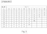
- FIG. 4 is a table showing simulation results of the laminated glass for vehicles according to the embodiment. 4 is a table showing simulation results of the laminated glass for vehicles according to the embodiment. 4 is a table showing simulation results of the laminated glass for vehicles according to the embodiment.
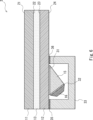
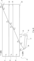
- FIG. 2 is a cross-sectional view showing another configuration example of the laminated glass for vehicles according to the embodiment;
- FIG. 2 is a cross-sectional view showing another configuration example of the laminated glass for vehicles according to the embodiment;
- FIG. 2 is a cross-sectional view showing another configuration example of the laminated glass for vehicles according to the embodiment;
- FIG. 1 is a cross-sectional view showing a configuration example of a laminated glass for vehicles according to an embodiment.
- the laminated glass for vehicles 1 according to this embodiment includes a first glass plate 11 , a second glass plate 12 , an intermediate adhesive layer 13 , an optical element 15 and a light source 16 .
- the laminated glass 1 for vehicles according to the present embodiment can be used, for example, as a vehicle window.
- Vehicle windows include, for example, roof glass, windshields, side windows, and the like.
- laminated glass for vehicles is also simply described as “laminated glass.”
- the first glass plate 11 has a first principal surface 21 and a second principal surface 22 .
- the second glass plate 12 has a third major surface 23 and a fourth major surface 24 .
- An intermediate adhesive layer 13 is arranged between the second main surface 22 of the first glass plate 11 and the third main surface 23 of the second glass plate 12 . That is, the intermediate adhesive layer 13 bonds the first glass plate 11 and the second glass plate 12 together.
- the material used for the intermediate adhesive layer 13 is not particularly limited, and any material may be used as long as it is an intermediate film used for laminated glass.
- the thickness of the intermediate adhesive layer 13 is also not particularly limited.
- the intermediate adhesive layer 13 may be composed of a plurality of layers.
- the intermediate adhesive layer 13 may include an intermediate film for sound insulation.
- the cross section of the intermediate adhesive layer 13 may have a shape other than a rectangular shape (for example, a wedge shape).
- the laminated glass 1 according to this embodiment may be flat or curved.
- the shape may include both a flat surface and a curved surface. That is, each of the first glass plate 11 and the second glass plate 12 may be a flat plate or a curved plate. In the following examples, both the first glass plate 11 and the second glass plate 12 are described as flat plates.
- the direction from the first glass plate 11 to the second glass plate 12 is defined as the first direction
- the direction from the second glass plate 12 to the first glass plate 11 is defined as the second direction. do.
- the first glass plate 11 When the laminated glass 1 is mounted on a vehicle, the first glass plate 11 may be positioned on the vehicle outer side and the second glass plate 12 may be positioned on the vehicle inner side.
- the first direction is the vehicle interior direction
- the second direction is the vehicle exterior direction.
- the optical element 15 is arranged between the fourth main surface 24 of the second glass plate 12 and the light source 16 and refracts the irradiation light 50 from the light source 16 . That is, the optical element 15 has a light receiving surface 19 facing the light source 16 , and the light source 16 introduces the irradiation light 50 to the light receiving surface 19 of the optical element 15 .
- the optical element 15 refracts the irradiation light 50 when the irradiation light 50 is incident on the light receiving surface 19 of the optical element 15 at a predetermined incident angle ⁇ 1 ( ⁇ 1 ⁇ 0°: see FIG. 2).
- the irradiation light 50 is typically the light with the highest luminous intensity among the lights emitted from the light source 16 .
- the irradiation light 50 When the irradiation light 50 has a plurality of incident angles ⁇ 1 , for example, when the light source 16 is approximated to a point light source, the irradiation light 50 is typically positioned at the center of the area where the illuminance is maximum on the light receiving surface 19. The light is assumed to be light along a line connecting with the light source 16 .
- the optical element 15 is attached to the fourth main surface 24 of the second glass plate 12 .
- the optical element 15 has an adhesive surface and is attached to the fourth main surface 24 so that the adhesive surface and the fourth main surface 24 are in direct contact or in contact via an optical adhesive layer.
- the optical element 15 is made of glass or a resin material.
- acrylic resin, epoxy resin, silicone rubber, or the like may be used as the resin material.
- a transparent material for the optical element 15 it may be colored to the extent that the effect of the present invention is not impaired.
- the cross-sectional shape of the optical element 15 (the cross section along the traveling plane of the irradiation light 50) is triangular.
- the longest side of the triangle is included in the adhesive surface, and of the other two sides, the side near the periphery of the laminated glass 1 is included in the light receiving surface 19 .
- the thickness of the optical element 15 increases from the periphery toward the center of the laminated glass 1 and decreases from a predetermined position.
- the predetermined position here is the position of the vertex of the triangle that is not included in the bonding surface. Since the optical element 15 has such a cross-sectional shape (thickness distribution), expansion and bending due to heat and moisture absorption can be suppressed.
- the cross-sectional shape of the optical element 15 is not limited to a triangular shape, and may be a polygonal shape such as a quadrangle, or a shape including a curved surface.
- the above-mentioned "predetermined position" may be any position between one end and the other end of the bonding surface (but not including end points).
- the optical element 15 includes a portion where the thickness increases and a portion where the thickness decreases from one end to the other end of the side forming the bonding surface in a cross-sectional view.
- the angle ⁇ p between the fourth main surface 24 of the second glass plate 12 and the light receiving surface 19 of the optical element 15 is preferably less than 90°, for example in the range of 10° to 80°.
- the angle ⁇ p may be 80° or less, 70° or less, 60° or less, 50° or less, 40° or less, 30° or less, or 20° or less. Also, the angle ⁇ p may be 10° or more, 20° or more, 30° or more, 40° or more, 50° or more, 60° or more, or 70° or more.
- a preferable range of the angle ⁇ p from the viewpoint of controlling the state of light introduced into the laminated glass 1 will be described later.
- the optical element 15 it is preferable to use a material having a coefficient of thermal expansion close to that of the second glass plate 12, in other words, a material with a small difference in coefficient of thermal expansion.
- a reflective layer may be provided on a surface of the optical element 15 other than the light receiving surface 19 through which light is introduced. When the reflective layer is provided in this manner, leakage of light from surfaces other than the light receiving surface 19 of the optical element 15 can be suppressed.
- the light source 16 is arranged to face the fourth main surface 24 of the second glass plate 12 and emits irradiation light 50 toward the fourth main surface 24 . That is, the light source 16 faces the fourth main surface 24 of the second glass plate 12 via the optical element 15, and the irradiation light 50 emitted from the light source 16 passes through the optical element 15 to the second glass plate. It is introduced into the fourth major surface 24 of the plate 12 .
- the irradiation light 50 may reach from the light receiving surface 19 to the fourth main surface 24 in a straight line, or may reach the light through reflection within the optical element 15 .
- a light emitting diode (LED), an organic EL element, or the like is used for the light source 16 .
- the light source 16 may be arranged so as to be separated from the light receiving surface 19 of the optical element 15 . Also, the light source 16 may be attached to the light receiving surface 19 of the optical element 15 .
- the laminated glass 1 includes one optical element 15 and one light source 16, but may include a plurality of optical elements 15 and a plurality of light sources 16, or the numbers thereof may differ.
- the number of light sources 16 may be greater than the number of optical elements 15 .
- the optical element 15 and the light source 16 may be provided on one pair of opposing sides of the laminated glass 1 or two pairs of opposing sides.
- FIG. 2 is a cross-sectional view for explaining the optical properties of the laminated glass according to this embodiment.
- the first glass plate 11 and the second glass plate 12 are bonded together with the intermediate adhesive layer 13 interposed therebetween, similarly to the configuration example shown in FIG.
- An optical element 15 is provided on the fourth main surface 24 of the second glass plate 12 .
- n 1 is the refractive index of air
- n 2 is the refractive index of the optical element 15
- n 3 is the refractive index of the first glass plate 11 and the second glass plate 12
- n 3 is the refractive index of the intermediate adhesive layer 13 .
- rate is n4 .
- the refractive indices of the first glass plate 11 and the second glass plate 12 may be different.
- irradiation light 50 (hereinafter also referred to as light 50 ) from the light source 16 (see FIG. 1 ) is incident on the light receiving surface 19 of the optical element 15 , the incident light 50 propagates inside the optical element 15 .
- the refractive index of air is n1
- the refractive index of the optical element 15 is n2 .
- the refracted light at the angle ⁇ 2 propagates inside the optical element 15 .
- the refractive index of the optical element 15 is n 2
- the refractive index of the second glass plate 12 is n 3 .
- the second glass plate 12 has a refractive index of n 3 and the intermediate adhesive layer 13 has a refractive index of n 4 . Then, the incident light is refracted and the refracted light with the refraction angle ⁇ 5 propagates inside the intermediate adhesive layer 13 .
- the refractive index of the intermediate adhesive layer 13 is n 4
- the refractive index of the first glass plate 11 is n 3 .
- the incident light is refracted and refracted light at a refraction angle ⁇ 4 propagates inside the first glass plate 11 .
- the light propagated inside the first glass plate 11 is totally reflected by the first main surface 21 of the first glass plate 11 or radiated into the air.
- the refractive index of the first glass plate 11 is n 3
- the refractive index of air is n 1
- the refraction angle of the light emitted into the air is ⁇ 6 .
- the light that propagates inside the first glass plate 11 is radiated into the air, part of the light that propagates inside the first glass plate 11 is emitted from the first main surface 21 of the first glass plate 11 . It is reflected and becomes reflected light.
- the purpose is to appropriately introduce light into the laminated glass 1, the light propagated inside the first glass plate 11 is totally reflected by the first main surface 21 of the first glass plate 11. is preferred.
- the optical element 15 is arranged between the fourth main surface 24 of the second glass plate 12 and the light source 16 to refract the irradiation light 50 from the light source 16 . That is, the optical element 15 is arranged to introduce the irradiation light 50 from the light source 16 to the fourth main surface 24 of the second glass plate 12 at an appropriate incident angle ⁇ 3 . Therefore, light can be properly introduced into the laminated glass.
- the incident angle ⁇ 1 of the irradiation light 50 to the light receiving surface 19 is preferably 0° or more and 45° or less. Note that the incident angle in the + direction shown in FIG. 2 is a positive incident angle. If the incident angle ⁇ 1 is too large, light does not enter the second glass plate 12 from the optical element 15 regardless of the refractive index n 2 of the optical element 15 , and as a result light enters the second glass plate 12 . sometimes not. In this case, the light 50 introduced from the light receiving surface 19 to the optical element 15 leaks out of the second glass plate 12 .
- the angle ⁇ p formed between the fourth main surface 24 of the second glass plate 12 and the light receiving surface 19 of the optical element 15 is large (for example, 70° to 80°), as the incident angle ⁇ 1 increases, the optical element It becomes difficult for light to enter the second glass plate 12 from 15 .
- the angle ⁇ p is small (for example, 20° to 30°)
- the light is totally reflected at the interface between the optical element 15 and the fourth main surface 24 of the second glass plate 12 as the incident angle ⁇ 1 increases.
- light may not enter the inside of the second glass plate 12 .
- the light 50 introduced from the light receiving surface 19 to the optical element 15 leaks out of the second glass plate 12 .
- the incident angle ⁇ 1 is preferably 20° or less, more preferably 15° or less, still more preferably 10° or less, even more preferably 5° or less, and 0° (substantially 0° may be ) is most preferred.
- the incident angle ⁇ 1 is set to 20° or less, it is possible to effectively suppress the problem that it is difficult for the light 50 to enter the second glass plate 12 from the optical element 15 .
- the angle ⁇ p is large (eg, 70° to 80°).
- the incident angle ⁇ 1 is set to 15° or less, the problem that the light 50 is difficult to enter the second glass plate 12 from the optical element 15 can be suppressed, and the interface reflectance at the interface between the air and the optical element 15 can be sufficiently increased. can be made as small as possible.
- the interface reflectance of the light 50 incident on the optical element 15 can be 1% or less.
- the incident angle ⁇ 1 is 10° or less, even when the angle ⁇ p is large (for example, around 80°), total reflection is unlikely to occur at the interface between the optical element 15 and the second glass plate 12, and the angle ⁇ p widens the adjustment range.
- the incident angle ⁇ 1 is 5° or less, total reflection is less likely to occur at the interface between the optical element 15 and the second glass plate 12 even when the angle ⁇ p is small, and the adjustment range of the angle ⁇ p is widened.
- the incident angle ⁇ 1 is 0°, substantially no reflection occurs when the light 50 enters the optical element 15 from the air.
- the incident angle ⁇ 1 of the irradiation light 50 to the light receiving surface 19 in the range of 0° or more and 45° or less, the incident light from the optical element 15 to the second glass plate 12 is The angle ⁇ 3 can be effectively adjusted.
- the incident angle ⁇ 4 of the light incident on the second glass plate 12 via the optical element 15 to the third main surface 23 is preferably 20° or more and less than 90°. Satisfying this condition makes it easier for the light to reach far (that is, to the center in the in-plane direction).
- the incident angle ⁇ 4 is preferably 30° or more, 40° or more, 50° or more, 60° or more, or 70° or more.
- the incident angle ⁇ 4 is important as an angle that determines the condition (angle ⁇ 6 ) under which light is totally reflected at the interface between the first glass plate 11 and air. In order to totally reflect the light at the interface between the first glass plate 11 and the air, it is preferable to set the incident angle ⁇ 4 to 40° or more. This is the same when the incident angle ⁇ 1 is other than 0°.
- the incident angle ⁇ 4 is preferably less than 80°, more preferably 76° or less.
- the incident angle ⁇ 4 exceeds 80°, total reflection of light is likely to occur at the interface between the second glass plate 12 and the intermediate adhesive layer 13, and the light is more likely to be reflected outside the vehicle (second direction side) than the third main surface 23. Adequate scattering may not be obtained if a scattering layer is present.
- the incident angle ⁇ 4 may be 80° or more and less than 90°.
- the scattering layer is provided on the vehicle inner side (first direction side) from the third main surface 23, appropriate scattering can be obtained.
- a scattering layer may be provided on the third principal surface 23 or the fourth principal surface 24 .
- the intermediate adhesive layer 13 and the first glass plate 11 since light can propagate within the second glass plate 12, absorption of light by the intermediate adhesive layer 13 and the first glass plate 11 can be suppressed. Therefore, it is effective when at least one of the intermediate adhesive layer 13 and the first glass plate 11 has a lower visible light transmittance than the second glass plate 12 .
- the first glass plate 11 colored glass such as privacy glass, heat absorbing glass, or the like can be used.
- a colored intermediate film or the like can be used as the intermediate adhesive layer 13 . Even when the incident angle ⁇ 4 is less than 80°, colored glass or the like may be used as the first glass plate 11 and a colored intermediate film or the like may be used as the intermediate adhesive layer 13 .
- the refractive index of the optical element 15 may be less than or equal to the refractive index of the second glass plate 12 .
- the value obtained by subtracting the refractive index of the optical element 15 from the refractive index of the second glass plate 12 may be 0.32 or less.
- the refractive index n3 of the second glass plate 12 is 1.52 and the refractive index n2 of the optical element 15 is 1.2 or more
- light with a wavelength of 589.3 nm (the D line of sodium) is used as a reference for the refractive index.
- the refractive index of the optical element 15 may be higher than that of the second glass plate 12 .
- the incident angle ⁇ 4 to the third main surface 23 can be increased.
- Refractive index n 2 , refractive index n 3 , and angle ⁇ p satisfy the relationship sin ⁇ p ⁇ (n 3 /n 2 ), so that total reflection at the interface between the second glass plate 12 and the intermediate adhesive layer 13 is It becomes easy to prevent and is preferable.
- the optical element 15 is arranged between the fourth main surface 24 of the second glass plate 12 and the light source 16 to refract the irradiation light 50 from the light source 16 .
- the incident angle ⁇ 1 of the irradiation light 50 to the optical element 15, the angle ⁇ p formed between the fourth main surface 24 of the second glass plate 12 and the light receiving surface 19 of the optical element 15, and the refractive index n of the optical element 15 are 2 , etc.
- the state of the light introduced into the laminated glass 1 can be controlled. Specifically, by setting these parameters to predetermined values, the light introduced into the laminated glass 1 can be propagated farther or closer, and the propagation range of the light introduced into the laminated glass 1 is can be controlled.
- simulation results for the laminated glass according to this embodiment will be described.
- the simulation conditions are as follows.
- the evaluation criteria for evaluation 1 were as follows. When light does not enter the second glass plate 12 because the light does not enter the interface between the optical element 15 and the second glass plate 12: XX (impossible) ⁇ If light does not enter the second glass plate 12 due to total reflection at the interface between the optical element 15 and the second glass plate 12: x (impossible) ⁇ When light leaks outside from the first glass plate 11 without total reflection on the first main surface 21 of the first glass plate 11: ⁇ (Possible) ⁇ When light is not leaked from the first glass plate 11 due to total reflection on the first main surface 21 of the first glass plate 11: ⁇ (good)
- FIGS. 3 and 4 show simulation results of evaluation 1.
- FIG. From the results shown in FIGS. 3 and 4, it can be said that light is easily introduced into the second glass plate 12 when the value of the incident angle ⁇ 1 is relatively small (for example, ⁇ 1 0° to 15°).
- the value of the incident angle ⁇ 1 is relatively small, it is easy to set the angle ⁇ p to a large value (for example, about 50° or more), so the contact area (contact width) between the optical element 15 and the second glass plate 12 is set to can be made smaller.
- the second Light can be introduced into the glass plate 12 .
- the value of the incident angle ⁇ 1 is relatively large, it is easy to set the angle ⁇ p to a small value (for example, about 40° or less), so the thickness of the optical element 15 can be reduced.
- the maximum light guide distance was the largest when the refractive index of the optical element 15 was 1.7 and ⁇ p was 60° (reference 11 times the light guiding distance).
- the maximum light guide distance was achieved under the conditions evaluated as " ⁇ " in the simulation of Evaluation 1, which was greater than the conditions evaluated as " ⁇ ".
- the case of total reflection at the interface between the second glass plate 12 and the intermediate adhesive layer 13 is not compared.
- the maximum light guide distance increased as the refractive index n 2 of the optical element 15 increased at each angle ⁇ p .
- the maximum light guide distance increased as the angle ⁇ p increased for each refractive index n 2 of the optical element 15 .
- the results of FIG. 5 also show that if the angle ⁇ p becomes small, it becomes possible to use an optical element 15 having a refractive index greater than the refractive index n 3 (1.52) of the glass flat plate. If the angle ⁇ p is greater than 80°, for example close to 90°, an optical element 15 with a refractive index greater than the refractive index n 3 (1.52) of the flat glass plate is substantially unusable.
- the incident angle ⁇ 1 of the irradiation light 50 to the optical element 15, the fourth main surface 24 of the second glass plate 12 and the optical element 15 The state of light introduced into the laminated glass 1 can be controlled by adjusting the angle ⁇ p formed with the light receiving surface 19 and the refractive index n 2 of the optical element 15 . Specifically, by setting these parameters to predetermined values, the light introduced into the laminated glass 1 can be propagated farther or closer, and the propagation range of the light introduced into the laminated glass 1 is can be controlled.
- 6 to 8 are cross-sectional views showing other structural examples of the laminated glass according to the present embodiment.
- the optical element 15 is attached to the fourth main surface 24 of the second glass plate 12 with the optical adhesive layer 31 interposed therebetween.
- the light source 16 is attached to the light receiving surface 19 (see FIG. 1) of the optical element 15 via the optical adhesive layer 32 .
- the optical adhesive layers 31 and 32 for example, acrylate-based, silicone-based, urethane-based, urethane-acrylate-based, epoxy-based, epoxy-acrylate-based, acrylamide-based, and methacrylamide-based resin compositions can be used.
- the optical adhesive layers 31 and 32 are adhesive members that transmit at least visible light, and may be either a curable transparent resin or a transparent adhesive sheet.
- the transparent adhesive sheet may be a sheet-like member in which the above-described resin composition is applied to a resin base material such as polyester.
- the cover 33 may be attached to the fourth main surface 24 of the second glass plate 12 .
- a cover 33 is provided to cover the light source 16 and the optical element 15 .
- the cover 33 is attached to the fourth major surface 24 of the second glass plate 12 via adhesive layers 35 and 36 .
- the adhesive layers 35 and 36 may use the same resin composition as the optical adhesive layers 31 and 32, or may use a different resin composition. Alternatively, the adhesive layers 35, 36 may be opaque.
- the cover 33 may be configured using resin or may be configured using metal. Also, the light source 16 may be fixed to the cover 33 . In the configuration example shown in FIG. 6, the cover 33 forms a closed space, but the cover 33 may form an open space. That is, the inside and outside of the cover 33 may be partially connected. In the invention according to this embodiment, the state of the light introduced into the laminated glass 2 can be controlled, so even if the cover 33 forms an open space, the light is less likely to leak out.
- a reflective layer may be provided inside the cover 33 in order to prevent the light from the light source 16 from leaking out of the cover 33 .
- the cover 33 is not arranged on the end face of the laminated glass (it is thin even if it is arranged).
- the first main surface 21 of the first glass plate 11, the fourth main surface 24 of the second glass plate 12, and the first main surface 21 of the first glass plate 11 and the second glass plate 12 A scattering layer may be provided in at least one place between the fourth main surfaces 24 of the .
- the second main surface 22 of the first glass plate 11 and the third main surface of the second glass plate 12 23, the interface where the intermediate adhesive layer 13 and the second main surface 22 of the first glass plate 11 are in contact, the interface where the intermediate adhesive layer 13 and the third main surface 23 of the second glass plate 12 are in contact, and the intermediate adhesive layer 13 Any of the internal.
- a scattering layer 42 may be provided at the interface where the intermediate adhesive layer 13 and the third main surface 23 of the second glass plate 12 are in contact.
- the scattering layer 42 in this manner, the scattered light can be extracted to the vehicle interior side (first direction side).
- a reflective layer a layer having a reflective function
- the reflective layer is provided in this way, the light scattered by the scattering layer 42 can be returned to the second glass plate 12 side, and the light can be used effectively.
- the constituent material and formation method of the scattering layer 42 are not particularly limited.
- a resin sheet such as polyurethane (PU), polyethylene (PE), or silicone may be used for the scattering layer 42 .
- the scattering layer 42 may be formed by subjecting the surface of the glass to surface processing such as sandblasting or etching.
- the scattering layer 42 may be formed using ceramic printing, paste, or the like.
- a shielding layer 41 may be provided.
- a shielding layer 41 is provided at the interface where the intermediate adhesive layer 13 and the second main surface 22 of the first glass plate 11 are in contact with each other.
- the shielding layer 41 may be arranged so that the cover 33 and the shielding layer 41 overlap when viewed from above. When the shielding layer 41 is provided in this manner, the light source 16 and the optical element 15 can be made less visible from the outside of the vehicle.
- the third main surface 23 of the second glass plate 12 and the third main surface 23 of the second glass plate 12 Light can be allowed to travel between the four main surfaces 24 .
- the light is totally reflected on the fourth major surface 24 of the second glass plate 12 .
- a scattering layer may be provided on at least one of the contacting interfaces to extract the scattered light to the vehicle interior.
- the light source 18 when arranging the light source 18 on the optical element 17, the light source 18 may be arranged on the opposite side of the end portion 27 of the laminated glass.
- the light source 18 may be arranged such that the direction of irradiation of the light from the light source 18 to the optical element 17 and the traveling direction of the light in the laminated glass are substantially opposite.
- the optical element 17 when the light source 18 is arranged on the opposite side of the edge 27 of the laminated glass, the optical element 17 can be arranged near the edge 27 of the laminated glass, and the range in which the scattered light can be extracted to the inside of the vehicle can be expanded.
- the reflecting surface 28 of the optical element 17 may reflect the light.
- the light emitted from the light source 18 is reflected by the reflecting surface 28 and enters the fourth main surface 24 of the second glass plate 12 .
- it is the same as the case described with reference to FIG.
Landscapes
- Engineering & Computer Science (AREA)
- Physics & Mathematics (AREA)
- General Engineering & Computer Science (AREA)
- General Physics & Mathematics (AREA)
- Optics & Photonics (AREA)
- Mechanical Engineering (AREA)
- Joining Of Glass To Other Materials (AREA)
Priority Applications (4)
| Application Number | Priority Date | Filing Date | Title |
|---|---|---|---|
| CN202380019949.3A CN118742524A (zh) | 2022-02-09 | 2023-02-02 | 车辆用夹层玻璃 |
| JP2023580206A JPWO2023153306A1 (https=) | 2022-02-09 | 2023-02-02 | |
| DE112023000846.9T DE112023000846T5 (de) | 2022-02-09 | 2023-02-02 | Fahrzeugverbundglas |
| US18/796,039 US12442974B2 (en) | 2022-02-09 | 2024-08-06 | Vehicular laminated glass having a light source and an optical element for introducing light into the glass |
Applications Claiming Priority (2)
| Application Number | Priority Date | Filing Date | Title |
|---|---|---|---|
| JP2022-018729 | 2022-02-09 | ||
| JP2022018729 | 2022-02-09 |
Related Child Applications (1)
| Application Number | Title | Priority Date | Filing Date |
|---|---|---|---|
| US18/796,039 Continuation US12442974B2 (en) | 2022-02-09 | 2024-08-06 | Vehicular laminated glass having a light source and an optical element for introducing light into the glass |
Publications (1)
| Publication Number | Publication Date |
|---|---|
| WO2023153306A1 true WO2023153306A1 (ja) | 2023-08-17 |
Family
ID=87564381
Family Applications (1)
| Application Number | Title | Priority Date | Filing Date |
|---|---|---|---|
| PCT/JP2023/003383 Ceased WO2023153306A1 (ja) | 2022-02-09 | 2023-02-02 | 車両用合わせガラス |
Country Status (5)
| Country | Link |
|---|---|
| US (1) | US12442974B2 (https=) |
| JP (1) | JPWO2023153306A1 (https=) |
| CN (1) | CN118742524A (https=) |
| DE (1) | DE112023000846T5 (https=) |
| WO (1) | WO2023153306A1 (https=) |
Cited By (1)
| Publication number | Priority date | Publication date | Assignee | Title |
|---|---|---|---|---|
| WO2025121088A1 (ja) * | 2023-12-06 | 2025-06-12 | Agc株式会社 | 車両用窓ガラス |
Families Citing this family (1)
| Publication number | Priority date | Publication date | Assignee | Title |
|---|---|---|---|---|
| JPWO2023153306A1 (https=) * | 2022-02-09 | 2023-08-17 |
Citations (3)
| Publication number | Priority date | Publication date | Assignee | Title |
|---|---|---|---|---|
| JPH07126046A (ja) * | 1993-10-27 | 1995-05-16 | Central Glass Co Ltd | 曲面ガラスへの樹脂材料の接着方法 |
| JP2020001454A (ja) * | 2018-06-25 | 2020-01-09 | Agc株式会社 | 通知装置 |
| WO2020201489A1 (en) * | 2019-04-05 | 2020-10-08 | Agc Glass Europe | Lidar assembly for automotive applications comprising an anti reflection unit |
Family Cites Families (16)
| Publication number | Priority date | Publication date | Assignee | Title |
|---|---|---|---|---|
| US5341230A (en) * | 1992-12-22 | 1994-08-23 | Hughes Aircraft Company | Waveguide holographic telltale display |
| JP2823470B2 (ja) * | 1993-03-09 | 1998-11-11 | シャープ株式会社 | 光走査装置及びそれを用いた表示装置並びに画像情報入出力装置 |
| JP3231655B2 (ja) * | 1997-03-28 | 2001-11-26 | シャープ株式会社 | 前方照明装置およびこれを備えた反射型液晶表示装置 |
| US8317352B2 (en) * | 2008-12-11 | 2012-11-27 | Robert Saccomanno | Non-invasive injection of light into a transparent substrate, such as a window pane through its face |
| FR2955539B1 (fr) | 2010-01-26 | 2016-03-25 | Saint Gobain | Vitrage lumineux de vehicule, fabrications |
| FR2955530B1 (fr) | 2010-01-26 | 2015-11-20 | Saint Gobain | Vitrage lumineux de vehicule, fabrications |
| DE102015000071B4 (de) * | 2015-01-12 | 2020-10-08 | Webasto SE | Deckel eines Fahrzeugdaches mit einer Beleuchtungseinrichtung |
| FR3034501A1 (fr) | 2015-04-03 | 2016-10-07 | Saint Gobain | Vitrage lumineux pour batiment, mobilier, vehicule de transport en commun |
| US10545346B2 (en) * | 2017-01-05 | 2020-01-28 | Digilens Inc. | Wearable heads up displays |
| DE102020109338B3 (de) * | 2020-04-03 | 2021-05-27 | Webasto SE | Fahrzeugscheibe mit Lichtquelle und Lichtleiterschicht |
| JP7570840B2 (ja) | 2020-07-16 | 2024-10-22 | 花王株式会社 | 水硬性組成物用分散剤 |
| WO2022096365A1 (de) | 2020-11-05 | 2022-05-12 | Saint-Gobain Glass France | Verglasung |
| JPWO2023153306A1 (https=) * | 2022-02-09 | 2023-08-17 | ||
| EP4344951B1 (en) * | 2022-09-29 | 2025-11-12 | Inalfa Roof Systems Group B.V. | A transparent roof panel assembly for a vehicle roof |
| CN118664978A (zh) * | 2023-03-17 | 2024-09-20 | 英纳法天窗系统集团有限公司 | 玻璃面板组件和设置有其的车辆的车顶组件 |
| DE102023116605A1 (de) * | 2023-06-23 | 2024-12-24 | Webasto SE | Fahrzeugscheibe mit Beleuchtungseinrichtung |
-
2023
- 2023-02-02 JP JP2023580206A patent/JPWO2023153306A1/ja active Pending
- 2023-02-02 CN CN202380019949.3A patent/CN118742524A/zh active Pending
- 2023-02-02 DE DE112023000846.9T patent/DE112023000846T5/de active Pending
- 2023-02-02 WO PCT/JP2023/003383 patent/WO2023153306A1/ja not_active Ceased
-
2024
- 2024-08-06 US US18/796,039 patent/US12442974B2/en active Active
Patent Citations (3)
| Publication number | Priority date | Publication date | Assignee | Title |
|---|---|---|---|---|
| JPH07126046A (ja) * | 1993-10-27 | 1995-05-16 | Central Glass Co Ltd | 曲面ガラスへの樹脂材料の接着方法 |
| JP2020001454A (ja) * | 2018-06-25 | 2020-01-09 | Agc株式会社 | 通知装置 |
| WO2020201489A1 (en) * | 2019-04-05 | 2020-10-08 | Agc Glass Europe | Lidar assembly for automotive applications comprising an anti reflection unit |
Cited By (1)
| Publication number | Priority date | Publication date | Assignee | Title |
|---|---|---|---|---|
| WO2025121088A1 (ja) * | 2023-12-06 | 2025-06-12 | Agc株式会社 | 車両用窓ガラス |
Also Published As
| Publication number | Publication date |
|---|---|
| JPWO2023153306A1 (https=) | 2023-08-17 |
| US20240393525A1 (en) | 2024-11-28 |
| DE112023000846T5 (de) | 2024-11-21 |
| CN118742524A (zh) | 2024-10-01 |
| US12442974B2 (en) | 2025-10-14 |
Similar Documents
| Publication | Publication Date | Title |
|---|---|---|
| US12442974B2 (en) | Vehicular laminated glass having a light source and an optical element for introducing light into the glass | |
| TWI451168B (zh) | 背光結構及其製造方法 | |
| TW201945168A (zh) | 光學裝置 | |
| CN106094097B (zh) | 导光板及应用其的背光模组、显示装置 | |
| CN103339535B (zh) | 光学复合片 | |
| TW202326264A (zh) | 前光模組與電泳顯示器 | |
| TW202028826A (zh) | 導光組件、背光模組及顯示設備 | |
| JPWO2023153306A5 (https=) | ||
| JP7624688B2 (ja) | 面光源装置及びフラットパネル型の表示装置 | |
| TW201738629A (zh) | 包括薄光導板與光耦合單元的背光單元 | |
| JP5669946B2 (ja) | 光学複合シート | |
| CN110325792A (zh) | 包含集成背光单元和显示面板的装置 | |
| US12392952B2 (en) | Illuminated pane-like glass element having reduced emittance via the lateral edge | |
| WO2014129646A1 (ja) | 導光板及び面発光装置 | |
| CN112782800B (zh) | 导光板、导光板组件及显示装置 | |
| JP7596771B2 (ja) | 調光部材、調光装置 | |
| JP7052539B2 (ja) | 表示装置 | |
| CN209215811U (zh) | 一种玻璃导光板全贴合背光模组 | |
| WO2025121088A1 (ja) | 車両用窓ガラス | |
| WO2024190861A1 (ja) | 車両用ガラス、及び車両用ガラスユニット | |
| WO2024120425A1 (zh) | 光线入射结构、车窗、车窗面板、车窗面板总成及车辆 | |
| JP2026015902A (ja) | 採光シート | |
| TW201516496A (zh) | 防眩光之導光結構及其光學膜片 | |
| JP2005010485A (ja) | 液晶表示装置及び液晶表示装置の製造方法 | |
| TW202516251A (zh) | 具有角落亮度補償結構的導光裝置、背光模組及顯示裝置 |
Legal Events
| Date | Code | Title | Description |
|---|---|---|---|
| 121 | Ep: the epo has been informed by wipo that ep was designated in this application |
Ref document number: 23752771 Country of ref document: EP Kind code of ref document: A1 |
|
| ENP | Entry into the national phase |
Ref document number: 2023580206 Country of ref document: JP Kind code of ref document: A |
|
| WWE | Wipo information: entry into national phase |
Ref document number: 202380019949.3 Country of ref document: CN |
|
| WWE | Wipo information: entry into national phase |
Ref document number: 112023000846 Country of ref document: DE |
|
| 122 | Ep: pct application non-entry in european phase |
Ref document number: 23752771 Country of ref document: EP Kind code of ref document: A1 |