WO2023153271A1 - 検出装置 - Google Patents
検出装置 Download PDFInfo
- Publication number
- WO2023153271A1 WO2023153271A1 PCT/JP2023/003025 JP2023003025W WO2023153271A1 WO 2023153271 A1 WO2023153271 A1 WO 2023153271A1 JP 2023003025 W JP2023003025 W JP 2023003025W WO 2023153271 A1 WO2023153271 A1 WO 2023153271A1
- Authority
- WO
- WIPO (PCT)
- Prior art keywords
- electrode
- layer
- detection device
- switching element
- cavity
- Prior art date
- Legal status (The legal status is an assumption and is not a legal conclusion. Google has not performed a legal analysis and makes no representation as to the accuracy of the status listed.)
- Ceased
Links
Images











Classifications
-
- H—ELECTRICITY
- H10—SEMICONDUCTOR DEVICES; ELECTRIC SOLID-STATE DEVICES NOT OTHERWISE PROVIDED FOR
- H10N—ELECTRIC SOLID-STATE DEVICES NOT OTHERWISE PROVIDED FOR
- H10N30/00—Piezoelectric or electrostrictive devices
- H10N30/101—Piezoelectric or electrostrictive devices with electrical and mechanical input and output, e.g. having combined actuator and sensor parts
-
- H—ELECTRICITY
- H10—SEMICONDUCTOR DEVICES; ELECTRIC SOLID-STATE DEVICES NOT OTHERWISE PROVIDED FOR
- H10N—ELECTRIC SOLID-STATE DEVICES NOT OTHERWISE PROVIDED FOR
- H10N39/00—Integrated devices, or assemblies of multiple devices, comprising at least one piezoelectric, electrostrictive or magnetostrictive element covered by groups H10N30/00 – H10N35/00
-
- B—PERFORMING OPERATIONS; TRANSPORTING
- B06—GENERATING OR TRANSMITTING MECHANICAL VIBRATIONS IN GENERAL
- B06B—METHODS OR APPARATUS FOR GENERATING OR TRANSMITTING MECHANICAL VIBRATIONS OF INFRASONIC, SONIC, OR ULTRASONIC FREQUENCY, e.g. FOR PERFORMING MECHANICAL WORK IN GENERAL
- B06B1/00—Methods or apparatus for generating mechanical vibrations of infrasonic, sonic, or ultrasonic frequency
- B06B1/02—Methods or apparatus for generating mechanical vibrations of infrasonic, sonic, or ultrasonic frequency making use of electrical energy
- B06B1/06—Methods or apparatus for generating mechanical vibrations of infrasonic, sonic, or ultrasonic frequency making use of electrical energy operating with piezoelectric effect or with electrostriction
- B06B1/0607—Methods or apparatus for generating mechanical vibrations of infrasonic, sonic, or ultrasonic frequency making use of electrical energy operating with piezoelectric effect or with electrostriction using multiple elements
- B06B1/0622—Methods or apparatus for generating mechanical vibrations of infrasonic, sonic, or ultrasonic frequency making use of electrical energy operating with piezoelectric effect or with electrostriction using multiple elements on one surface
- B06B1/0629—Square array
-
- G—PHYSICS
- G06—COMPUTING OR CALCULATING; COUNTING
- G06F—ELECTRIC DIGITAL DATA PROCESSING
- G06F3/00—Input arrangements for transferring data to be processed into a form capable of being handled by the computer; Output arrangements for transferring data from processing unit to output unit, e.g. interface arrangements
- G06F3/01—Input arrangements or combined input and output arrangements for interaction between user and computer
- G06F3/03—Arrangements for converting the position or the displacement of a member into a coded form
- G06F3/041—Digitisers, e.g. for touch screens or touch pads, characterised by the transducing means
- G06F3/0412—Digitisers structurally integrated in a display
-
- G—PHYSICS
- G06—COMPUTING OR CALCULATING; COUNTING
- G06F—ELECTRIC DIGITAL DATA PROCESSING
- G06F3/00—Input arrangements for transferring data to be processed into a form capable of being handled by the computer; Output arrangements for transferring data from processing unit to output unit, e.g. interface arrangements
- G06F3/01—Input arrangements or combined input and output arrangements for interaction between user and computer
- G06F3/03—Arrangements for converting the position or the displacement of a member into a coded form
- G06F3/041—Digitisers, e.g. for touch screens or touch pads, characterised by the transducing means
- G06F3/043—Digitisers, e.g. for touch screens or touch pads, characterised by the transducing means using propagating acoustic waves
- G06F3/0433—Digitisers, e.g. for touch screens or touch pads, characterised by the transducing means using propagating acoustic waves in which the acoustic waves are either generated by a movable member and propagated within a surface layer or propagated within a surface layer and captured by a movable member
-
- H—ELECTRICITY
- H04—ELECTRIC COMMUNICATION TECHNIQUE
- H04R—LOUDSPEAKERS, MICROPHONES, GRAMOPHONE PICK-UPS OR LIKE ACOUSTIC ELECTROMECHANICAL TRANSDUCERS; ELECTRIC HEARING AIDS; PUBLIC ADDRESS SYSTEMS
- H04R17/00—Piezoelectric transducers; Electrostrictive transducers
-
- H—ELECTRICITY
- H10—SEMICONDUCTOR DEVICES; ELECTRIC SOLID-STATE DEVICES NOT OTHERWISE PROVIDED FOR
- H10N—ELECTRIC SOLID-STATE DEVICES NOT OTHERWISE PROVIDED FOR
- H10N30/00—Piezoelectric or electrostrictive devices
- H10N30/80—Constructional details
- H10N30/87—Electrodes or interconnections, e.g. leads or terminals
- H10N30/872—Interconnections, e.g. connection electrodes of multilayer piezoelectric or electrostrictive devices
-
- G—PHYSICS
- G06—COMPUTING OR CALCULATING; COUNTING
- G06F—ELECTRIC DIGITAL DATA PROCESSING
- G06F2203/00—Indexing scheme relating to G06F3/00 - G06F3/048
- G06F2203/041—Indexing scheme relating to G06F3/041 - G06F3/045
- G06F2203/04101—2.5D-digitiser, i.e. digitiser detecting the X/Y position of the input means, finger or stylus, also when it does not touch, but is proximate to the digitiser's interaction surface and also measures the distance of the input means within a short range in the Z direction, possibly with a separate measurement setup
-
- G—PHYSICS
- G06—COMPUTING OR CALCULATING; COUNTING
- G06F—ELECTRIC DIGITAL DATA PROCESSING
- G06F3/00—Input arrangements for transferring data to be processed into a form capable of being handled by the computer; Output arrangements for transferring data from processing unit to output unit, e.g. interface arrangements
- G06F3/01—Input arrangements or combined input and output arrangements for interaction between user and computer
- G06F3/03—Arrangements for converting the position or the displacement of a member into a coded form
- G06F3/041—Digitisers, e.g. for touch screens or touch pads, characterised by the transducing means
- G06F3/043—Digitisers, e.g. for touch screens or touch pads, characterised by the transducing means using propagating acoustic waves
Definitions
- the present disclosure relates to an ultrasonic transducer using ultrasonic waves and a detection device using the same.
- An object of the present disclosure is to provide a detection device having a low-cost, highly reliable ultrasonic transducer.
- a detection device is a detection device including a plurality of ultrasonic transducers that transmit and receive ultrasonic waves, the detection device including a flexible substrate, a plurality of first electrodes and at least one second electrode, a laminate including a circuit layer laminated on the flexible substrate and a piezoelectric layer laminated on the circuit layer; and a first surface of the laminate and a second surface opposite to the first surface.
- FIG. 1 is a plan view showing a schematic configuration of a detection device provided with an ultrasonic element according to Embodiment 1.
- FIG. FIG. 2 is a block diagram showing a configuration example of the detection device according to the first embodiment.
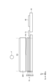
- FIG. 3 is a schematic diagram showing a schematic cross-sectional configuration of the detection device of Embodiment 1.
- FIG. 4 is a schematic diagram showing the relationship between the object to be detected and the detection device in the space above the detection area.
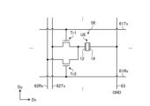
- FIG. 5 is a circuit diagram showing one detection area among a plurality of detection areas according to the first embodiment.
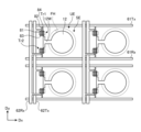
- FIG. 6 is a plan view showing the detection area of Embodiment 1.
- FIG. 7 is a timing chart showing the operation of one ultrasonic transducer in Embodiment 1.
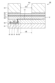
- FIG. 8 is a cross-sectional view showing the detection area and the frame area of Embodiment 1.
- FIG. 9 is a cross-sectional view showing the detection area of Embodiment 2.
- FIG. 10 is a cross-sectional view showing the detection area of Embodiment 3.
- FIG. 11 is a cross-sectional view showing the detection area of the fourth embodiment.
- FIG. 12 is a cross-sectional view showing the detection area of the fifth embodiment.
- FIG. 13 is a circuit diagram showing one detection area among a plurality of detection areas according to the fifth embodiment.
- FIG. 14 is a cross-sectional view showing the detection area of Embodiment 6.
- FIG. 15 is a plan view showing the first electrode and the second electrode of Embodiment 6.
- FIG. 16 is a plan view showing a first electrode and a second electrode according to Modification 1 of Embodiment 6.
- FIG. 17 is a plan view showing a first electrode and a second electrode according to Modification 2 of Embodiment 6.
- FIG. 18 is a plan view showing a first electrode and a second electrode according to Modification 3 of Embodiment 6.
- FIG. 19 is a plan view showing a first electrode and a second electrode according to Modification 4 of Embodiment 6.
- FIG. FIG. 20 is a plan view showing the detection area of Embodiment 7.
- FIG. 21 is a cross-sectional view showing the detection area of Embodiment 7.
- FIG. 1 is a plan view showing a schematic configuration of a detection device provided with an ultrasonic element according to Embodiment 1.
- the detection device 1 includes an ultrasonic transducer array 10 and a controller 20 .
- the ultrasonic transducer array 10 has a flexible substrate 51 and a plurality of ultrasonic transducer elements SE provided in the detection area AA of the flexible substrate 51 .
- one first electrode 12 is arranged for one ultrasonic transducer SE.
- the flexible substrate 51 has a frame area GA outside the detection area AA.
- a signal line selection circuit 16 and a scanning circuit 17 are arranged in the frame area GA.
- the control unit 20 has a control board 43 , an ultrasonic processing circuit 40 mounted on the control board 43 , a power supply circuit 41 , and an interface circuit 42 .
- a control board 43 is electrically connected to the flexible board 51 via the wiring board 31 .
- the wiring board 31 is, for example, a flexible printed board.
- the control board 43 is, for example, a rigid board.
- the power supply circuit 41 supplies power to the interface circuit 42 and the ultrasonic processing circuit 40 based on power supplied from the outside.
- the power supply circuit 41 supplies necessary power to the signal line selection circuit 16, the scanning circuit 17, the ultrasonic processing circuit 40, and the ultrasonic transducer SE via the wiring board 31 based on the power supplied from the outside.
- the power supply circuit 41 is a circuit that manages power required for the signal line selection circuit 16 , the scanning circuit 17 , the ultrasonic transducer SE, the interface circuit 42 and the ultrasonic processing circuit 40 .
- the interface circuit 42 is, for example, a USB controller IC, and controls communication between the A/D conversion circuit 23 and a host controller (not shown) of the host device on which the detection system is mounted. Power supplied from the outside is supplied to the power supply circuit 41 via the interface circuit 42 .
- the detection area AA of the flexible substrate 51 is an area provided with a plurality of ultrasonic conversion elements SE arranged in a matrix in the Dx direction (first direction) and the Dy direction (second direction).
- the flexible substrate 51 is, for example, a flexible printed circuit board (FPC Flexible Printed Circuits).
- the Dx direction (first direction) and the Dy direction (second direction) intersect and are orthogonal. Also, in the present disclosure, the direction perpendicular to the Dx direction (first direction) and the Dy direction (second direction) is defined as the Dz direction (third direction).
- ultrasonic transducer elements SE are arranged in the Dx direction and four ultrasonic transducer elements SE are arranged in the Dy direction. It is provided in the detection area AA of the substrate 51 .
- the plurality of ultrasonic transducer elements SE is an ultrasonic transducer array. Note that the plurality of ultrasonic transducer elements SE may be arranged in a staggered arrangement. Also, the number of ultrasonic transducers SE provided in the detection area AA of the flexible substrate 51 is not limited to the embodiment.
- FIG. 2 is a block diagram showing a configuration example of the detection device of Embodiment 1.
- the ultrasonic processing circuit 40 includes a signal transmission circuit 21, a signal detection circuit 22, an A/D conversion circuit 23, a signal processing circuit 24, a coordinate extraction circuit 25, a storage circuit 26, Prepare.
- the ultrasonic processing circuit 40 is, for example, a PLD (Programmable Logic Device) such as an FPGA (Field Programmable Gate Array).
- the signal transmission circuit 21 transmits the oscillation pulse Set(n) (n is a natural number from 1 to N, N is the number of electrodes in the detection area AA) to the ultrasonic transducer. It is delivered to the first electrode 12 (see FIG. 1) of the SE.
- the signal detection circuit 22 is, for example, an analog front end (AFE) IC.
- the signal detection circuit 22 detects the detection signal Det(n) output from the ultrasonic transducer array 10 (n is a natural number from 1 to N, N is a number assigned to the electrodes within the detection area AA, and the maximum The value is the number of electrodes.), the detection value S(n) of each first electrode 12 is generated.
- the A/D conversion circuit 23 samples the detected value S(n) of each first electrode 12 and converts it into a digital signal.
- the signal processing circuit 24 performs predetermined signal processing on the detected value S(n) from the A/D conversion circuit 23 . Specifically, the signal processing circuit 24 performs comparison arithmetic processing of the detected value S(n).
- the coordinate extraction circuit 25 extracts the spatial coordinates of the position where the object to be detected exists based on the result of the comparison operation processing of the signal processing circuit 24 .
- the coordinate extraction circuit 25 uses the detection value S(n) of each first electrode 12 processed by the signal processing circuit 24 to extract a space indicating the position of the object F in the space on the detection area AA shown in FIG. Extract the coordinates R (Rx, Ry, Rz).
- Information on the spatial coordinates R (Rx, Ry, Rz) is output to an external device via the interface circuit 42 (see FIG. 1).
- the storage circuit 26 has a function of storing information on the spatial coordinates R (Rx, Ry, Rz) extracted by the coordinate extraction circuit 25 .
- FIG. 3 is a schematic diagram showing a schematic cross-sectional configuration of the detection device of Embodiment 1.
- the detection device 1 of Embodiment 1 is arranged to face the display panel 200 .
- the detection area AA (see FIG. 1) of the ultrasonic transducer array 10 and the display area DA of the display panel 200 are arranged so as to overlap in the Dz direction (third direction).
- the detection area AA of the ultrasonic transducer array 10 and the display area DA of the display panel 200 are arranged so as to entirely overlap. may be arranged so as to overlap with the
- the display panel 200 is exemplified by, for example, a liquid crystal display (LCD).
- the display panel 200 may be, for example, an organic EL display (OLED: Organic Light Emitting Diode) or an inorganic EL display (micro LED, mini LED).
- OLED Organic Light Emitting Diode
- micro LED mini LED
- the ultrasonic transducer array 10 includes a flexible substrate 51 , a frame layer 52 , a circuit layer 53 , a piezoelectric layer 54 and a protective layer 55 .
- the ultrasonic transducer array 10 is laminated in the order of a frame layer 52 , a flexible substrate 51 , a circuit layer 53 , a piezoelectric layer 54 and a protective layer 55 from the opposite side of the display panel 200 .
- FIG. 4 is a schematic diagram showing the relationship between the object to be detected and the detection device in the space above the detection area.
- the ultrasonic transducer SE converts the oscillation pulse Set(n) to generate an ultrasonic wave Tu, and the ultrasonic wave Tu is transmitted.
- the ultrasonic conversion element SE receives the ultrasonic wave Ru reflected by the object to be detected F (for example, operator's fingers, etc.) and converts it into a detection signal Det(n).
- the coordinate extraction circuit 25 determines whether the detected object F (for example, the operator's fingers, etc.) exists on the detection area AA. Generates spatial coordinates that indicate a position.
- the ultrasonic transducer SE detects the object to be detected F (for example, fingers of the operator) based on the time until it receives the ultrasonic wave Ru reflected by the object to be detected F (for example, fingers of the operator). can also measure the distance of the object to be detected F (for example, fingers of the operator).
- FIG. 5 is a circuit diagram showing one detection area among the plurality of detection areas of the first embodiment.
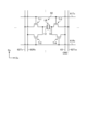
- FIG. 6 is a plan view showing the detection area of Embodiment 1.
- FIG. 5 is a circuit diagram showing one detection area among the plurality of detection areas of the first embodiment.
- FIG. 6 is a plan view showing the detection area of Embodiment 1.
- the scanning circuit 17 shown in FIG. 1 is a circuit that drives a plurality of scanning lines 61Tx and scanning lines 61Rx shown in FIGS. 5 and 6 based on various control signals.
- the scanning circuit 17 serves both as a driving circuit for scanning the scanning lines 61Tx of the plurality of ultrasonic transducers SE and as a driving circuit for scanning the scanning lines 61Rx of the plurality of ultrasonic transducers SE.
- the scanning circuit 17 sequentially selects a plurality of scanning lines 61Tx and 61Rx, and supplies gate drive signals to the selected scanning lines 61Tx and 61Rx. Thereby, the scanning circuit 17 selects a plurality of ultrasonic transducers SE connected to the scanning lines 61Tx and 61Rx.
- the scanning lines 61Tx and the scanning lines 61Rx are made of metal materials such as aluminum (Al), gold, molybdenum, and titanium.
- the signal line selection circuit 16 is a switch circuit that sequentially or simultaneously selects a plurality of transmission signal lines 62Tx and a plurality of reception signal lines 62Rx.
- the signal line selection circuit 16 is, for example, a multiplexer.
- the signal line selection circuit 16 connects the selected transmission signal line 62Tx and the signal transmission circuit 21 based on the selection signal supplied from the ultrasonic processing circuit 40 .
- the signal line selection circuit 16 connects the selected reception signal line 62Rx and the signal detection circuit 22 based on the selection signal supplied from the ultrasonic processing circuit 40 . Thereby, the signal line selection circuit 16 outputs the detection signal Det(n) of the ultrasonic transducer SE to the signal detection circuit 22 .
- Metal materials such as aluminum (Al), gold, molybdenum, and titanium are used for the transmission signal line 62Tx and the reception signal line 62Rx.
- Each ultrasonic transducer SE includes a first switching element Tr1, a second switching element Tr2, and a membrane vibrator UE.
- the first switching element Tr1 switches and controls the connection between the transmission signal line 62Tx and the membrane vibrator UE.
- the second switching element Tr2 switches and controls the connection between the reception signal line 62Rx and the membrane vibrator UE.
- the first electrode 12 on one end side of the membrane vibrating body UE is connected to the drain of the first switching element Tr1 and the drain of the second switching element Tr2, and the second electrode 14 on the other end side of the membrane vibrating body UE is connected to the reference potential. It is connected to a reference potential wiring 63 to which GND is supplied. As shown in FIG. 6, the first electrode 12 is connected to the drain of the first switching element Tr1 and the drain of the second switching element Tr2 via the connection wiring 12W.
- the transmission signal line 62Tx is connected to the source of the first switching element Tr1.
- the reception signal line 62Rx is connected to the source of the second switching element Tr2.
- the scanning line 61Tx is connected to the gate of the first switching element Tr1.
- the scanning line 61Rx is connected to the gate of the second switching element Tr2.
- the connection to the drain of the first switching element Tr1 and the second switching element Tr2 and the connection to the source of the first switching element Tr1 and the second switching element Tr2 may be interchanged.
- the reference potential wiring 63 is made of a metal material such as aluminum (Al), gold, molybdenum, titanium, or the like.
- the circuits shown in FIGS. 5 and 6 may further include other transistors, signal amplifier circuits, bandpass filters, capacitors, and the like.
- FIG. 7 is a timing chart showing the operation of one ultrasonic transducer in the first embodiment.
- transmission of ultrasonic waves and reception of ultrasonic waves are processed in a time division manner.
- a gate drive signal is transmitted to the scanning line 61Tx selected by the scanning circuit 17, and the signal line selection circuit 16 transmits the oscillation pulse Set(n) from the signal transmission circuit 21 to the selected transmission signal line 62Tx. transmit.
- the membrane vibrator UE vibrates based on the oscillation pulse Set(n) to generate the ultrasonic waves Tu.
- the frequency of the ultrasonic wave Tu is, for example, 1 kHz or more and 1 MHz or less.
- a gate drive signal is transmitted to the scanning line 61Rx selected by the scanning circuit 17, and the signal line selection circuit 16 connects the selected reception signal line 62Rx and the signal detection circuit 22.
- the membrane vibrator UE Upon receiving the ultrasonic wave Ru, the membrane vibrator UE converts the ultrasonic wave Ru into a detection signal Det(n) of an electric signal, and the detection signal Det(n) is transmitted to the signal detection circuit 22 .
- the timing at which the gate driving signal is transmitted to the scanning line 61Tx and the timing at which the gate driving signal is transmitted to the scanning line 61Rx are shifted.
- the timings at which the drive signals are transmitted may be the same. By doing so at the same time, although there is a risk of crosstalk between the oscillation pulse Set(n) and the detection signal Det(n), a closer object can be detected.
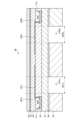
- FIG. 8 is a cross-sectional view showing the detection area and the frame area of Embodiment 1.
- the flexible substrate 51 on which the cross section of one ultrasonic transducer SE in the detection area AA is described together with the cross section of the frame area GA is a flexible resin substrate, such as polyimide resin. Used.
- the thickness of the flexible substrate 51 is 1 ⁇ m or more and 100 ⁇ m or less.
- a cavity FH is opened in the frame layer 52 for each ultrasonic transducer SE.
- a region that overlaps with the cavity FH in plan view becomes the membrane vibrator UE.
- the cavity FH surrounds the first electrode 12 in plan view.
- the frame layer 52 is, for example, polyimide resin or metal foil.
- the thickness of the frame layer 52 is 1 ⁇ m or more and 100 ⁇ m or less.
- the frame layer 52 is less bendable than the flexible substrate 51 .
- the frame layer 52 is made of the same material as the flexible substrate 51, so that the frame layer 52 is thicker than the flexible substrate 51, so that the flexible substrate overlaps the first electrode 12 and the cavity FH in plan view. 51 vibrate together and function as a membrane vibrator UE.
- the Young's modulus and thickness of the frame layer 52 are set so that the frame layer 52 is more difficult to bend than the flexible substrate 51 .
- the cavity FH is circular with a diameter ⁇ D.
- Diameter ⁇ D is smaller than the range surrounded by scanning lines 61Tx, scanning lines 61Rx, transmission signal lines 62Tx, and reception signal lines 62Rx shown in FIG.
- the diameter ⁇ D is, for example, 0.1 mm or more and 5 mm or less.
- the piezoelectric layer 54 is made of an inorganic material such as PZT (lead zirconate titanate) or AlN (aluminum nitride), or an organic material such as polyvinylidene fluoride resin (polyvinylidene difluoride resin).
- the thickness of the piezoelectric layer 54 is, for example, 10 nm or more and 10000 nm or less.
- the piezoelectric layer 54 may optionally include buffer layers, crystal adjustment layers, protective layers, matching layers, backing layers, and the like.
- the piezoelectric layer 54 is formed over the entire sensing area AA.
- the area where the piezoelectric layer 54 is formed may have the same size as the area of the cavity FH in plan view, and may be provided so as to overlap the area of the cavity FH in plan view.
- the piezoelectric layer 54 may have a similar shape to the area of the cavity FH in plan view, and may be larger than the boundary of the area of the cavity FH.
- the piezoelectric layer 54 may be similar in shape to the area of the cavity FH in plan view, smaller than the area of the cavity FH, and larger than the first electrode 12 .
- the circuit layer 53 and piezoelectric layer 54 are formed on a glass substrate, and the circuit layer 53 and piezoelectric layer 54 are transferred from the glass substrate to the flexible substrate 51 .
- a piezoelectric layer 54 is formed on the glass substrate.
- a first electrode 12 is formed on the piezoelectric layer 54 .
- a first resin layer 71 is formed on the first electrode 12 .
- Metal materials such as aluminum (Al), gold, molybdenum, and titanium are used for the first electrode 12 .
- the first electrode 12 may be an alloy material containing at least one of these metal materials or a laminate of at least two of these metal materials.
- a gate electrode 82 is formed on the first resin layer 71 when viewed from the glass substrate.
- a second resin layer 72 is laminated on the gate electrode 82 .
- a source electrode 83 and a drain electrode 84 are formed on the second resin layer 72 .
- the drain electrode 84 and the first electrode 12 are electrically connected via a through hole 85 .
- the second resin layer 72 around the source electrode 83 and the drain electrode 84 is covered with a third resin layer 73 .
- a semiconductor layer 81 is formed on the source electrode 83 and the drain electrode 84, and the semiconductor layer 81 and the source electrode 83 and the drain electrode 84 are bonded to each other.
- the semiconductor layer 81, gate electrode 82, source electrode 83 and drain electrode 84 function as a first switching element Tr1.
- the gate electrode 82, the source electrode 83, the drain electrode 84, and the through hole 8 are made of metal material such as aluminum (Al), gold, molybdenum, and titanium.
- the gate electrode 82, the source electrode 83, the drain electrode 84, and the through hole 85 may be an alloy material containing at least one of these metal materials or a laminate of at least two of these metal materials. Since the second switching element Tr2 has the same configuration as the first switching element Tr1, detailed description thereof will be omitted.
- the semiconductor layer 81 is an oxide semiconductor. More preferably, the semiconductor layer 81 is a transparent amorphous oxide semiconductor (TAOS) among oxide semiconductors. Leakage current is suppressed by using an oxide semiconductor for the semiconductor layer 81 . That is, it is possible to reduce the leak current from the non-selected transistor of the first switching element Tr1 or the second switching element Tr2. Therefore, the detection device 1 can improve the S/N ratio.
- the semiconductor layer 81 is not limited to this, and may be a microcrystalline oxide semiconductor, an amorphous oxide semiconductor, polysilicon, low temperature polysilicon (LTPS: Low Temperature Polycrystalline Silicon), or the like.
- a fourth resin layer 74 is formed on the semiconductor layer 81 and the third resin layer 73 . Since the circuit layer 53 is transferred from the glass substrate to the flexible substrate 51, the stacking order is reversed when viewed from the flexible substrate 51. FIG.
- the second resin layer 72 is an inorganic insulating film such as silicon nitride.
- the first resin layer 71, the third resin layer 73, and the fourth resin layer 74 may be inorganic insulating films or organic insulating films, and are organic insulating films such as acrylic resin, for example. If the first resin layer 71, the third resin layer 73, and the fourth resin layer 74 are organic insulating films, the circuit layer 53 is less likely to crack. The thickness of the circuit layer 53 may be partially changed. It may be thinned or removed.
- a second electrode 14 is formed on the second surface opposite to the first surface of the piezoelectric layer 54 on which the first electrode 12 is formed.
- the second electrode 14 is also called a counter electrode, and is connected via a through hole 87 to the reference potential wiring 63 in the frame area GA.
- Metal materials such as aluminum (Al), gold, molybdenum, and titanium are used for the second electrode 14 .
- the second electrode 14 may be an alloy material containing at least one of these metal materials or a laminate of at least two of these metal materials.
- the second electrode 14 is covered with a protective layer 55 of an organic insulating film such as acrylic resin.
- the second electrode 14 is in contact with the surface of the piezoelectric layer 54 opposite to the surface with which the first electrode 12 is in contact, and the piezoelectric layer 54 is sandwiched between the first electrode 12 and the second electrode 14 .
- the second electrode 14 is provided across the plurality of ultrasonic transducers SE, and serves as the second electrode 14 common to the plurality of ultrasonic transducers SE. This reduces the electrical resistance of the second electrode 14 .
- the flexible substrate 51 and the frame layer 52 are bonded via an adhesive layer 56 .
- the adhesive layer 56 has tackiness on both sides, and has a cavity FH formed by press working or the like while being bonded to the frame layer 52 .
- the ultrasonic transducer SE is formed by transfer in the example shown in FIG. 8, it may be formed by other methods.
- a flexible substrate 51 is formed on a glass substrate, and a circuit layer 53, a piezoelectric layer 54, a second electrode 14, and a protective layer 55 are formed thereon. After that, the flexible substrate 51 may be separated from the glass substrate, and the flexible substrate 51 and the frame layer 52 may be bonded.
- the circuit layer 53, the piezoelectric layer 54, the second electrode 14, and the protective layer 55 are sequentially laminated, the order of lamination is not reversed even when viewed from the flexible substrate 51.
- the first switching element Tr1 is provided at a position that does not overlap the cavity FH in plan view, and the first switching element Tr1 and the first electrode 12 are electrically connected at a position that does not overlap the cavity FH in plan view. .
- the frame layer 52 may be formed by covering the region of the cavity FH with a photoresist, coating or forming a film around the photoresist, and then removing the photoresist.
- the frame layer 52 may be 3D printed and directly formed on the surface of the flexible substrate 51 .
- the detection device 1 of Embodiment 1 includes a plurality of ultrasonic transducers SE that transmit and receive ultrasonic waves.
- the detection device 1 includes a laminate and a frame layer 52 laminated to a first surface of the laminate and a second surface opposite to the first surface.
- the laminate includes a flexible substrate 51 , a circuit layer 53 laminated on the flexible substrate 51 , and a piezoelectric layer 54 laminated on the circuit layer 53 .
- the frame layer 52 is bonded to the flexible substrate 51 .
- the ultrasonic transducer SE includes a first electrode 12 in contact with the piezoelectric layer 54 and a second electrode 14 in contact with the piezoelectric layer 54 .
- the frame layer 52 has a cavity FH at a position overlapping the first electrode 12 in plan view.
- the flexible substrate 51 bends more easily in response to vibration than a substrate made of glass, silicon, or the like, so that the bonding surfaces of the flexible substrate 51, the circuit layer 53, and the piezoelectric layer 54 are less likely to break. Further, the membrane vibrator UE can be manufactured at low cost only by bonding the flexible substrate 51 and the frame layer 52 having the cavity FH.
- FIG. 9 is a cross-sectional view showing the detection area of Embodiment 2.
- FIG. 9 the same reference numerals are assigned to the same configurations as in the first embodiment, and the description may be omitted.
- a cross-section of one ultrasonic transducer SE of the detection area AA is shown.
- the frame layer 52 is bonded to one surface of the flexible substrate 51, but in the second embodiment, the frame layer 52 is attached to the circuit layer 53 and the piezoelectric layer 54 on the opposite side of the first embodiment. It is in.
- the frame layer 52 is bonded to one surface of the protective layer 55 via an adhesive layer 56 .
- a cavity FH is opened in the frame layer 52 for each ultrasonic transducer SE.
- the detection device 1 of Embodiment 2 includes a plurality of ultrasonic transducers SE that transmit and receive ultrasonic waves.
- the detection device 1 includes a laminate and a frame layer 52 laminated to the second of the first side of the laminate and the second side opposite to the first side.
- the laminate includes a flexible substrate 51 , a circuit layer 53 laminated on the flexible substrate 51 , and a piezoelectric layer 54 laminated on the circuit layer 53 .
- the frame layer 52 is bonded to a protective layer 55 on the opposite side of the laminate from the flexible substrate 51 .
- the ultrasonic transducer SE includes a first electrode 12 in contact with the piezoelectric layer 54 and a second electrode 14 in contact with the piezoelectric layer 54 .
- the frame layer 52 has a cavity FH at a position overlapping the first electrode 12 in plan view.
- the flexible substrate 51 bends more easily in response to vibration than a substrate made of glass, silicon, or the like, so that the bonding surfaces of the flexible substrate 51, the circuit layer 53, and the piezoelectric layer 54 are less likely to break. Further, the membrane vibrator UE can be manufactured at low cost only by bonding the flexible substrate 51 and the frame layer 52 having the cavity FH.
- FIG. 10 is a cross-sectional view showing the detection area of Embodiment 3.
- FIG. 10 shows a cross section of one ultrasonic transducer SE of the detection area AA.
- a frame layer 52A is bonded to one surface of the flexible substrate 51 via an adhesive layer 56A.
- a cavity FHA is opened in the frame layer 52A for each ultrasonic transducer SE.
- a frame layer 52B is bonded to one surface of the protective layer 55 via an adhesive layer 56B.
- a cavity FHB is opened in the frame layer 52B for each ultrasonic transducer SE.
- the detection device 1 of Embodiment 3 includes a plurality of ultrasonic transducers SE that transmit and receive ultrasonic waves.
- the detection device 1 includes a laminate, a frame layer 52A laminated on a first side of the laminate, and a frame layer 52B laminated on a second side opposite to the first side.
- the laminate includes a flexible substrate 51 , a circuit layer 53 laminated on the flexible substrate 51 , and a piezoelectric layer 54 laminated on the circuit layer 53 .
- the circuit layer 53 and the piezoelectric layer 54 are sandwiched between the frame layers 52A and 52B.
- the ultrasonic transducer SE includes a first electrode 12 in contact with the piezoelectric layer 54 and a second electrode 14 in contact with the piezoelectric layer 54 .
- the frame layer 52 has a cavity FHA and a cavity FHB at positions overlapping the first electrode 12 in plan view.
- the cavity FHA of one frame layer 52A and the cavity FHB of the other frame layer 52B are positioned to overlap each other in plan view.
- the flexible substrate 51 bends more easily in response to vibration than a substrate made of glass, silicon, or the like, so that the bonding surfaces of the flexible substrate 51, the circuit layer 53, and the piezoelectric layer 54 are less likely to break. Further, the membrane vibrator UE can be manufactured at low cost only by bonding the flexible substrate 51 and the frame layer 52 having the cavity FH.
- FIG. 11 is a cross-sectional view showing the detection area of the fourth embodiment.
- the same reference numerals are assigned to the same configurations as in the first to third embodiments, and the description thereof may be omitted.
- FIG. 11 shows a cross-section of one ultrasonic transducer SE of the detection area AA.
- a reference potential wiring 63 is routed to each ultrasonic transducer SE.
- the reference potential wiring 63 is formed in a layer different from that of the source electrode 83 and the drain electrode 84, and is formed in the same layer as the semiconductor layer 81, for example.
- a relay wiring 88 in the same layer as the first electrode 12 is connected to the reference potential wiring 63 via a through hole 87A.
- the second electrode 14 and the relay wiring 88 are connected via a through hole 89 . Thereby, the frame area GA can be narrowed.
- the second electrode 14 of each ultrasonic transducer SE is provided in a region overlapping the cavity FH in plan view. Since adjacent second electrodes 14 are separated from each other, crosstalk of ultrasonic waves Ru detected by adjacent ultrasonic transducer elements SE is reduced.
- the second electrode 14 and the reference potential wiring 63 are electrically connected at a position not overlapping the cavity FH in plan view, the possibility of disconnection of the reference potential wiring 63 is reduced.
- FIG. 12 is a cross-sectional view showing the detection area of the fifth embodiment.
- FIG. 13 is a circuit diagram showing one detection area among a plurality of detection areas according to the fifth embodiment.
- the same reference numerals are assigned to the same configurations as in the first to fourth embodiments, and the description thereof may be omitted.
- FIG. 12 shows a cross-section of one ultrasonic transducer SE of the detection area AA.
- the second electrode 14 is electrically connected to the third switching element Tr3. Since the third switching element Tr3 has the same configuration as the first switching element Tr1, detailed description thereof will be omitted.
- the drain electrode 84 of the third switching element Tr3 and the second electrode 14 are electrically connected via a through hole 85, a relay wiring 88 and a through hole 89. As shown in FIG.
- Each ultrasonic transducer SE includes a first switching element Tr1, a second switching element Tr2, a third switching element Tr3, a fourth switching element Tr4, and a membrane vibrator UE.
- the first switching element Tr1 switches and controls the connection between the transmission signal line 62Tx and the membrane vibrator UE.
- the second switching element Tr2 switches and controls the connection between the reception signal line 62Rx and the membrane vibrator UE.
- the third switching element Tr3 switches and controls the connection between the transmission signal line 62Txx and the membrane vibrator UE.
- the second switching element Tr2 switches and controls the connection between the reference potential wiring 63 and the membrane vibrator UE.
- the second electrode 14 is connected to the drain of the third switching element Tr3.
- the transmission signal line 62Txx is connected to the source of the third switching element Tr3.
- a signal opposite in phase to the oscillation pulse Set(n) of the transmission signal line 62Tx (first transmission signal line) is transmitted to the transmission signal line 62Txx (second transmission signal line).
- the second electrode 14 is connected to the drain of the fourth switching element Tr4.
- the reference potential wiring 63 is connected to the source of the fourth switching element Tr4.
- the first switching element Tr1 and the third switching element Tr3 are simultaneously turned on, and the second switching element Tr2 and the fourth switching element Tr4 are simultaneously turned off.
- the transmission signal line 62Tx transmits the signal of the oscillation pulse Set(n) to the first electrode 12 via the first switching element Tr1
- the transmission signal line 62Txx transmits the signal to the second electrode 14 via the third switching element Tr3.
- a signal opposite in phase to the oscillation pulse Set(n) is transmitted.
- the amplitude of the signal applied to the piezoelectric layer 54 is double that of the first embodiment, and the ultrasonic output is improved.
- the first switching element Tr1 and the third switching element Tr3 are simultaneously turned off, and the second switching element Tr2 and the fourth switching element Tr4 are simultaneously turned on.
- the reception signal line 62Rx and the first electrode 12 are connected via the second switching element Tr2, and the reference potential wiring 63 and the second electrode 14 are connected via the third switching element Tr3.
- the detection signal Det(n) of the ultrasonic transducer SE is output to the signal detection circuit 22 .
- the second electrode 14 of each ultrasonic transducer SE is provided in a region overlapping the cavity FH in plan view. Adjacent second electrodes 14 are separated from each other. In the ultrasonic transducers SE not selected by the scanning circuit 17, the second electrode 14 becomes the reference potential GND, and noise from the ultrasonic transducers SE not selected by the scanning circuit 17 is suppressed.
- the reverse running signal of the oscillation pulse Set(n) is transmitted to the second electrode 14, so the amplitude of the membrane vibrator UE increases.
- the second electrode 14 becomes the reference potential GND, and the influence of the vibration of the other ultrasonic transducers SE can be suppressed.
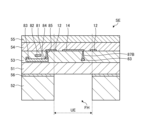
- FIG. 14 is a cross-sectional view showing the detection area of Embodiment 6.
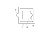
- FIG. 15 is a plan view showing the first electrode and the second electrode of Embodiment 6.
- FIG. 14 is the XIV-XIV cross section of FIG.
- the same components as in Embodiments 1 to 5 are denoted by the same reference numerals, and description thereof may be omitted.
- FIG. 14 shows a cross-section of one ultrasonic transducer SE of the detection area AA.
- a reference potential wiring 63 is routed to each ultrasonic transducer SE.
- the reference potential wiring 63 is formed in a layer different from that of the source electrode 83 and the drain electrode 84, and is formed in the same layer as the semiconductor layer 81, for example.
- the second electrode 14 in the same layer as the first electrode 12 is connected to the reference potential wiring 63 via the through hole 87B. As shown in FIG. 15, the second electrode 14 is in contact with the same side of the piezoelectric layer 54 as the first electrode 12 is in contact with. And the second electrode 14 is inside the second electrode 14 . Thereby, the frame area GA can be narrowed.
- the second electrode 14 of each ultrasonic transducer SE is provided in a region overlapping the cavity FH in plan view. Since adjacent second electrodes 14 are separated from each other, crosstalk of ultrasonic waves Ru detected by adjacent ultrasonic transducer elements SE is reduced.
- the area where the second electrode 14 is formed has a similar shape to the area of the cavity FH in plan view and is smaller than the area of the cavity FH.
- the area where the first electrode 12 is formed overlaps with the boundary of the area of the cavity FH in plan view, and the first electrode 12 has an annular shape.
- FIG. 16 is a plan view showing the first electrode and the second electrode according to Modification 1 of Embodiment 6.
- FIG. 16 in Modification 1, the second electrode 14 is rectangular, and the outer diameter of the first electrode 12 is rectangular and annular.
- the first electrode 12 and the second electrode 14 are the same layer as in the sixth embodiment.
- FIG. 17 is a plan view showing a first electrode and a second electrode according to Modification 2 of Embodiment 6.
- FIG. 17 the region where the second electrode 14 is formed is similar in shape to the region of the cavity FH in plan view, and is smaller than the region of the cavity FH.
- the area where the first electrode 12 is formed overlaps with the boundary of the area of the cavity FH in plan view, and the first electrode 12 has an annular shape. Note that the first electrode 12 and the second electrode 14 are the same layer as in the sixth embodiment.
- a through hole 87B is arranged outside the first electrode 12, and the through hole 87B and the second electrode 14 are connected by wiring.
- the reference potential wiring 63 does not overlap with the region overlapping the cavity FH region in plan view, so that the reference potential wiring 63 is less susceptible to the vibration of the membrane vibrating body UE, and the reliability of the detection device 1 is improved. improves.
- FIG. 18 is a plan view showing a first electrode and a second electrode according to Modification 3 of Embodiment 6.
- FIG. 18 As shown in FIG. 18, in Modification 3, the first electrode 12 and the second electrode 14 are rectangular, and the first electrode 12 and the second electrode 14 are adjacent to each other. Note that the first electrode 12 and the second electrode 14 are the same layer as in the sixth embodiment.
- a through-hole 87B is arranged at a position outside an area overlapping with the area of the cavity FH in plan view, and the through-hole 87B and the second electrode 14 are connected by wiring.
- the reference potential wiring 63 does not overlap with the region overlapping the cavity FH region in plan view, so that the reference potential wiring 63 is less susceptible to the vibration of the membrane vibrating body UE, and the reliability of the detection device 1 is improved. improves.
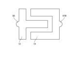
- FIG. 19 is a plan view showing a first electrode and a second electrode according to Modification 4 of Embodiment 6.
- FIG. 19 As shown in FIG. 19, in Modification 4, the first electrode 12 and the second electrode 14 are interdigitated comb electrodes. Note that the first electrode 12 and the second electrode 14 are the same layer as in the sixth embodiment.
- a through-hole 87B is arranged at a position outside an area overlapping with the area of the cavity FH in plan view, and the through-hole 87B and the second electrode 14 are connected by wiring.
- the reference potential wiring 63 does not overlap with the region overlapping the cavity FH region in plan view, so that the reference potential wiring 63 is less susceptible to the vibration of the membrane vibrating body UE, and the reliability of the detection device 1 is improved. improves.
- FIG. 20 is a plan view showing the detection area of Embodiment 7.
- FIG. 21 is a cross-sectional view showing the detection area of Embodiment 7.
- FIG. 20 is the XX-XX' section of FIG.
- the same components as in Embodiments 1 to 6 are denoted by the same reference numerals, and description thereof may be omitted.
- a cross section of one ultrasonic transducer SE of the detection area AA is shown.
- the first electrode 12Tx and the first electrode 12Rx are arranged for one ultrasonic transducer SE.
- the first electrode 12Tx is an ultrasonic transmitting electrode that generates an ultrasonic wave Tu
- the first electrode 12Rx is an ultrasonic receiving electrode that receives an ultrasonic wave Ru.
- Each ultrasonic transducer SE includes a first switching element Tr1, a second switching element Tr2, a membrane oscillator UETx, and a membrane oscillator UERx.
- the first switching element Tr1 and the first electrode 12Tx are electrically connected via a through hole 85Tx.
- the first switching element Tr1 switches and controls the connection between the transmission signal line 62Tx and the membrane vibrator UETx.
- the second switching element Tr2 and the first electrode 12Rx are electrically connected via a through hole 85Rx.
- the second switching element Tr2 switches and controls the connection between the reception signal line 62Rx and the membrane vibrator UERx.
- a first cavity FHTx and a second cavity FHRx are opened in the frame layer 52 for each ultrasonic transducer SE.
- the frame layer 52 has a first cavity FHTx at a position overlapping with one of the first electrodes 12Tx in plan view, and a second cavity FHRx at a position overlapping with the other first electrode 12Rx.
- a region that overlaps with the first cavity FHTx in plan view becomes the membrane vibrator UETx.
- a region that overlaps with the second cavity FHRx in plan view becomes the membrane vibrator UERx.
- Ultrasonic wave transmission and ultrasonic wave reception are processed in a time-division manner.
- the membrane vibrating body UETx and the membrane vibrating body UERx are operated separately.
- the vibrator UERx is less affected.
- the detection device 1 has a shorter detection cycle and improved detection accuracy.
- the first electrode 12Tx may be arranged on the first row of ultrasonic transducer elements SE, and the first electrode 12Rx may be arranged on the second row of ultrasonic transducer elements SE.
Landscapes
- Engineering & Computer Science (AREA)
- General Engineering & Computer Science (AREA)
- Physics & Mathematics (AREA)
- Theoretical Computer Science (AREA)
- Human Computer Interaction (AREA)
- General Physics & Mathematics (AREA)
- Acoustics & Sound (AREA)
- Mechanical Engineering (AREA)
- Signal Processing (AREA)
- Transducers For Ultrasonic Waves (AREA)
Priority Applications (2)
| Application Number | Priority Date | Filing Date | Title |
|---|---|---|---|
| JP2023580186A JP7659667B2 (ja) | 2022-02-09 | 2023-01-31 | 検出装置 |
| US18/795,498 US12376493B2 (en) | 2022-02-09 | 2024-08-06 | Detecting device |
Applications Claiming Priority (2)
| Application Number | Priority Date | Filing Date | Title |
|---|---|---|---|
| JP2022-018689 | 2022-02-09 | ||
| JP2022018689 | 2022-02-09 |
Related Child Applications (1)
| Application Number | Title | Priority Date | Filing Date |
|---|---|---|---|
| US18/795,498 Continuation US12376493B2 (en) | 2022-02-09 | 2024-08-06 | Detecting device |
Publications (1)
| Publication Number | Publication Date |
|---|---|
| WO2023153271A1 true WO2023153271A1 (ja) | 2023-08-17 |
Family
ID=87564203
Family Applications (1)
| Application Number | Title | Priority Date | Filing Date |
|---|---|---|---|
| PCT/JP2023/003025 Ceased WO2023153271A1 (ja) | 2022-02-09 | 2023-01-31 | 検出装置 |
Country Status (3)
| Country | Link |
|---|---|
| US (1) | US12376493B2 (https=) |
| JP (1) | JP7659667B2 (https=) |
| WO (1) | WO2023153271A1 (https=) |
Citations (2)
| Publication number | Priority date | Publication date | Assignee | Title |
|---|---|---|---|---|
| JP2006166985A (ja) * | 2004-12-13 | 2006-06-29 | Fuji Photo Film Co Ltd | 体腔内診断用超音波プローブ、および体腔内診断用超音波プローブの作製方法 |
| JP6776481B1 (ja) * | 2020-01-30 | 2020-10-28 | サンコール株式会社 | 超音波トランスデューサー及びその製造方法 |
Family Cites Families (2)
| Publication number | Priority date | Publication date | Assignee | Title |
|---|---|---|---|---|
| US10478858B2 (en) * | 2013-12-12 | 2019-11-19 | Qualcomm Incorporated | Piezoelectric ultrasonic transducer and process |
| US11484911B2 (en) * | 2019-04-12 | 2022-11-01 | Bfly Operations, Inc. | Bottom electrode via structures for micromachined ultrasonic transducer devices |
-
2023
- 2023-01-31 JP JP2023580186A patent/JP7659667B2/ja active Active
- 2023-01-31 WO PCT/JP2023/003025 patent/WO2023153271A1/ja not_active Ceased
-
2024
- 2024-08-06 US US18/795,498 patent/US12376493B2/en active Active
Patent Citations (2)
| Publication number | Priority date | Publication date | Assignee | Title |
|---|---|---|---|---|
| JP2006166985A (ja) * | 2004-12-13 | 2006-06-29 | Fuji Photo Film Co Ltd | 体腔内診断用超音波プローブ、および体腔内診断用超音波プローブの作製方法 |
| JP6776481B1 (ja) * | 2020-01-30 | 2020-10-28 | サンコール株式会社 | 超音波トランスデューサー及びその製造方法 |
Also Published As
| Publication number | Publication date |
|---|---|
| US20240397827A1 (en) | 2024-11-28 |
| JPWO2023153271A1 (https=) | 2023-08-17 |
| US12376493B2 (en) | 2025-07-29 |
| JP7659667B2 (ja) | 2025-04-09 |
Similar Documents
| Publication | Publication Date | Title |
|---|---|---|
| US12016249B2 (en) | Piezoelectric sensor and manufacturing method thereof, method for recognizing fingerprint, and electronic device | |
| CN109815918B (zh) | 指纹识别模组及其制作方法和驱动方法、显示装置 | |
| US10497748B2 (en) | Integrated piezoelectric micromechanical ultrasonic transducer pixel and array | |
| JP6065421B2 (ja) | 超音波プローブおよび超音波検査装置 | |
| US10001552B2 (en) | Three-port piezoelectric ultrasonic transducer | |
| CN104424420B (zh) | 电子装置 | |
| CN102194991B (zh) | 压电元件、压电传感器、电子设备及压电元件的制造方法 | |
| CN113473338B (zh) | 振动产生装置和包括该振动产生装置的显示设备 | |
| WO2018176796A1 (zh) | 阵列基板、显示面板、显示设备及阵列基板制备方法 | |
| TW202026941A (zh) | 超音波指紋偵測和相關設備及方法 | |
| CN111782090B (zh) | 显示模组、超声波触控检测方法、超声波指纹识别方法 | |
| JP6205704B2 (ja) | 超音波測定装置、ヘッドユニット、プローブ及び診断装置 | |
| JP6123171B2 (ja) | 超音波トランスデューサー、超音波プローブおよび超音波検査装置 | |
| US11829552B2 (en) | Display panel, control method thereof, and display device combining a fingerprint recognition function and a touch detection function | |
| WO2016061410A1 (en) | Three-port piezoelectric ultrasonic transducer | |
| US11018291B2 (en) | Ultrasonic device and ultrasonic apparatus | |
| CN102988079A (zh) | 超声波探头及超声波图像诊断装置 | |
| WO2021056713A1 (zh) | 显示面板及显示装置 | |
| WO2018163963A1 (ja) | 超音波センサおよび超音波センサ装置 | |
| TWI777485B (zh) | 指紋感測裝置 | |
| JP7659667B2 (ja) | 検出装置 | |
| US20250256303A1 (en) | Ultrasonic transducer, fingerprint recognition module, and electronic device | |
| JP6466719B2 (ja) | 音響発生装置および携帯端末 | |
| US20260090276A1 (en) | Transducer, transduction apparatus, and terminal | |
| JP6288235B2 (ja) | 超音波プローブおよび超音波検査装置 |
Legal Events
| Date | Code | Title | Description |
|---|---|---|---|
| 121 | Ep: the epo has been informed by wipo that ep was designated in this application |
Ref document number: 23752736 Country of ref document: EP Kind code of ref document: A1 |
|
| ENP | Entry into the national phase |
Ref document number: 2023580186 Country of ref document: JP Kind code of ref document: A |
|
| NENP | Non-entry into the national phase |
Ref country code: DE |
|
| 122 | Ep: pct application non-entry in european phase |
Ref document number: 23752736 Country of ref document: EP Kind code of ref document: A1 |