WO2023153263A1 - ガイドワイヤ - Google Patents
ガイドワイヤ Download PDFInfo
- Publication number
- WO2023153263A1 WO2023153263A1 PCT/JP2023/002955 JP2023002955W WO2023153263A1 WO 2023153263 A1 WO2023153263 A1 WO 2023153263A1 JP 2023002955 W JP2023002955 W JP 2023002955W WO 2023153263 A1 WO2023153263 A1 WO 2023153263A1
- Authority
- WO
- WIPO (PCT)
- Prior art keywords
- core shaft
- optical fiber
- guidewire
- tubular body
- guide wire
- Prior art date
- Legal status (The legal status is an assumption and is not a legal conclusion. Google has not performed a legal analysis and makes no representation as to the accuracy of the status listed.)
- Ceased
Links
Images


Classifications
-
- A—HUMAN NECESSITIES
- A61—MEDICAL OR VETERINARY SCIENCE; HYGIENE
- A61M—DEVICES FOR INTRODUCING MEDIA INTO, OR ONTO, THE BODY; DEVICES FOR TRANSDUCING BODY MEDIA OR FOR TAKING MEDIA FROM THE BODY; DEVICES FOR PRODUCING OR ENDING SLEEP OR STUPOR
- A61M25/00—Catheters; Hollow probes
- A61M25/01—Introducing, guiding, advancing, emplacing or holding catheters
- A61M25/09—Guide wires
Definitions
- the technology disclosed in this specification relates to guidewires.
- FORS Fiber Optic Real Shape
- a technique called FORS Fiber Optic Real Shape
- a long medical device using FORS comprises a cylindrical body and an optical fiber disposed in the hollow part of the cylindrical body, and analyzes the reflected light of the laser beam transmitted through the optical fiber. By measuring the strain of the optical fiber, the position and shape of the optical fiber and thus the elongated medical device are identified and imaged in real time (see Patent Document 1, for example).
- FORS Field Optic Real Shape
- a cylindrical body is used as a member that supports the optical fiber. It is difficult to increase the rigidity of the cylindrical body because the ratio of the wall thickness to the outer diameter is small and the processing difficulty is high. Therefore, in the conventional elongated medical device, the rigidity of the tubular body, and thus the rigidity of the elongated medical device, is low, resulting in a medical device such as a catheter (hereinafter referred to as a "combined device"). ) and the bending endurance of the tip end.
- This specification discloses a technology capable of solving the above-described problems.
- a guidewire disclosed herein includes a core shaft, a first tubular body, and an optical fiber.
- the first tubular body is a tubular member arranged on the proximal end side of the core shaft and having a first lumen.
- the optical fiber passes through the first lumen and extends toward the distal end side of the core shaft along the outer peripheral surface of the core shaft.
- the optical fiber is supported by the core shaft instead of the hollow tubular body. Since the core shaft does not have a hollow portion, it can have higher rigidity than the hollow cylindrical body, provided that the outer diameter is the same. Therefore, according to the present guidewire, the presence of the core shaft can increase the rigidity of the guidewire, and as a result, for example, the supportability of a combined device such as a catheter and the bending durability of the tip of the guidewire can be improved. be able to.
- the position and shape of the guidewire can be specified (imaging) using optical fibers, and the rigidity of the guidewire can be increased due to the presence of the core shaft. It is possible to improve the supportability of the device and the bending durability of the tip.
- the core shaft may have a tapered shaft portion that constitutes the base end portion of the core shaft and whose outer diameter gradually decreases toward the base end side.
- a groove extending from the proximal end of the core shaft to the distal side is formed in the outer peripheral surface of the core shaft, and at least a portion along the extending direction of the optical fiber is formed with the It is good also as a structure accommodated in the groove
- the groove at the proximal end of the core shaft may have a tapered groove whose depth gradually increases toward the proximal end.
- the groove does not have a tapered groove portion, and the groove depth is constant to the base end of the groove. It is possible to reduce the risk of breakage of the optical fiber.
- the core shaft has a large-diameter portion and a small-diameter portion positioned distally of the large-diameter portion and having an outer diameter smaller than that of the large-diameter portion. further covers at least the small-diameter portion of the core shaft and the distal end portion of the optical fiber, and the inner diameter of the portion covering the small-diameter portion is equal to the outer diameter of the large-diameter portion of the core shaft and the optical fiber It is good also as a structure provided with the 2nd cylindrical body smaller than the sum with an outer diameter of.
- the optical fiber extending toward the distal end along the outer peripheral surface of the large-diameter portion of the core shaft is positioned so as to face the small-diameter portion of the core shaft, and the inner peripheral surface of the second cylindrical body moves the core. It is held close to the shaft. Therefore, according to the present guidewire, the presence of the second cylindrical body can enhance the followability of the optical fiber when the core shaft is deformed, and the position and shape of the guidewire can be specified (imaging) using the optical fiber. ) can be improved.
- the inner diameter of the second tubular body is equal to the outer diameter of the core shaft and the outer diameter of the optical fiber at at least a part of the position along the extending direction of the second tubular body. It is good also as a structure which corresponds to the sum of. According to the present guidewire, the presence of the second cylindrical body allows the optical fiber to maintain contact with the core shaft, thereby effectively enhancing the followability of the optical fiber when the core shaft is deformed. The accuracy of identifying (imaging) the position and shape of the guidewire using optical fibers can be effectively improved.
- Explanatory drawing schematically showing the configuration of the guide wire 100 in the first embodiment Explanatory drawing schematically showing the configuration of the guide wire 100 in the first embodiment. Explanatory drawing schematically showing the configuration of the guide wire 100 in the first embodiment. Explanatory drawing schematically showing the configuration of the guide wire 100 in the first embodiment. Explanatory drawing schematically showing the configuration of the guide wire 100 in the first embodiment. Explanatory drawing schematically showing the configuration of the guide wire 100 in the first embodiment. Explanatory drawing schematically showing the configuration of the guide wire 100a in the second embodiment. Explanatory drawing schematically showing the configuration of the guide wire 100b in the third embodiment. Explanatory drawing schematically showing the configuration of the guide wire 100b in the third embodiment. Explanatory drawing schematically showing the configuration of the guide wire 100b in the third embodiment.
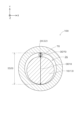
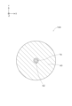
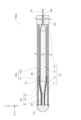
- A. First embodiment: A-1. Configuration of guidewire 100: 1 to 5 are explanatory diagrams schematically showing the configuration of the guidewire 100 according to the first embodiment. 1 shows the configuration of the longitudinal section (YZ section) of the guidewire 100, and FIG. 2 shows the configuration of the transverse section (XY section) of the guidewire 100 at the position II-II in FIG. 3 shows the cross-sectional configuration of guidewire 100 at position III-III of FIG. 1, and FIG. 4 shows guidewire 100 at position IV-IV of FIG. , and FIG. 5 shows the cross-sectional configuration of guidewire 100 at position VV of FIG. 1, illustration of part of the guide wire 100 is omitted.
- FIG. 1 shows the configuration of the longitudinal section (YZ section) of the guidewire 100
- FIG. 2 shows the configuration of the transverse section (XY section) of the guidewire 100 at the position II-II in FIG. 3 shows the cross-sectional configuration of guidewire 100 at position III-III of FIG. 1
- FIG. 4 shows guidewire 100 at position IV
- the Z-axis positive direction side is the tip side (distal side) inserted into the body
- the Z-axis negative direction side is the proximal side (proximal side) operated by an operator such as a doctor.
- FIG. 1 shows the guidewire 100 as a whole in a straight line substantially parallel to the Z-axis direction, at least a portion of the guidewire 100 is flexible enough to be curved. have.
- the distal end of the guidewire 100 and its components is referred to as the "distal end,” the distal end and its vicinity as the “distal portion,” and the proximal end as the "proximal end.”
- the base end and the vicinity thereof are referred to as the “base end portion”.
- the guidewire 100 is an elongated medical device that is inserted into a biological lumen.
- the total length of the guide wire 100 is, for example, approximately 1500 mm to 3200 mm.
- the guide wire 100 of the present embodiment has a FORS function that uses the optical fiber 70 to identify and image the position and shape of the guide wire 100 in real time without X-ray irradiation.
- the guidewire 100 is used alone or in combination with other imaging techniques (for example, CT and MRI) to identify the position and shape of the guidewire 100 itself and the biological lumen into which the guidewire 100 is inserted. Used.
- Guidewire 100 may also be used to guide companion devices such as catheters.
- the guidewire 100 includes a core shaft 10 , a proximal tubular body 60 , an outer tubular body 20 , an inner tubular body 40 and an optical fiber 70 .
- the core shaft 10 is a long rod-shaped member extending along the central axis of the guide wire 100 .
- the shape of the cross section at each position of the core shaft 10 can take any shape, but is, for example, substantially circular.
- the core shaft 10 has a small diameter portion 11, a first tapered portion 12, a large diameter portion 13, and a second tapered portion .
- the small diameter portion 11 constitutes the tip portion of the core shaft 10 and has a substantially constant outer diameter.
- the first tapered portion 12 is adjacent to the proximal side of the small diameter portion 11 and is a tapered (frustum-shaped) portion in which the outer diameter gradually increases from the distal end side to the proximal end side.
- the outer diameter of the first tapered portion 12 substantially matches the outer diameter of the small diameter portion 11 at the boundary position with the small diameter portion 11, and the outer diameter of the large diameter portion 13 at the boundary position with the large diameter portion 13. Almost match.
- the large-diameter portion 13 is adjacent to the proximal end side of the first taper portion 12 and has a substantially constant outer diameter larger than the outer diameter of the small-diameter portion 11 .
- the second tapered portion 14 is adjacent to the proximal side of the large-diameter portion 13 and constitutes the proximal end portion of the core shaft 10, and has a tapered shape (truncated cone shape) in which the outer diameter gradually decreases from the distal end side to the proximal end side. ).
- the outer diameter of the second tapered portion 14 substantially matches the outer diameter of the large diameter portion 13 at the boundary position with the large diameter portion 13 .
- the second tapered portion 14 is an example of a tapered shaft portion.
- the proximal side tubular body 60 is a tubular member that is disposed proximal to the core shaft 10 and has an optical fiber lumen 62 .
- the base-side cylindrical body 60 is configured by a tubular body having a uniform cross section.
- the shape of the cross section of the proximal-side cylindrical body 60 can take any shape, but is, for example, substantially annular.
- the optical fiber lumen 62 is formed, for example, at a position coaxial with the central axis of the guide wire 100 .
- the proximal-side tubular body 60 is an example of a first tubular body, and the optical fiber lumen 62 is an example of a first lumen.
- the optical fiber 70 is a linear member that transmits optical signals to realize the FORS described above. As shown in FIGS. 1 to 5 , the optical fiber 70 passes through the optical fiber lumen 62 of the proximal tubular body 60 and extends along the outer peripheral surface of the core shaft 10 toward the distal end of the core shaft 10 . are doing. More specifically, the optical fiber 70 extends along the outer peripheral surface of the core shaft 10 over substantially the entire length of the core shaft 10 (over the second tapered portion 14, the large diameter portion 13, the first tapered portion 12, and the small diameter portion 11). It extends from the proximal side toward the distal side while bending at the bottom.
- the positions of the optical fibers 70 along the circumferential direction of the core shaft 10 are the same at each position along the extending direction of the core shaft 10 . That is, when the core shaft 10 is viewed from a predetermined direction (the Y-axis direction in the example of FIG. 1), the optical fiber 70 extends substantially straight.
- the optical fiber 70 is joined to, for example, the distal end portion (small diameter portion 11) and the proximal end portion (second taper portion 14) of the core shaft 10 by, for example, an adhesive.
- the portion of the optical fiber 70 closer to the proximal end than the proximal-side cylindrical body 60 is used for transmission and reception of laser light via the optical fiber 70, measurement of distortion of the optical fiber 70 based on reflected light, and imaging based on the distortion. It is connected to a control device (not shown) that controls such as.
- the outer tubular body 20 is a tubular member arranged around the core shaft 10 and the optical fiber 70 so as to cover the core shaft 10 and the optical fiber 70 .
- the outer tubular body 20 has a distal outer tubular body 21 and a proximal outer tubular body 22 .
- the outer tubular body 20 is an example of a third tubular body.
- the distal outer cylindrical body 21 constitutes the distal end portion of the outer cylindrical body 20 and covers the small diameter portion 11 of the core shaft 10, the first tapered portion 12, and part of the large diameter portion 13 on the distal side. ing.
- the tip outer cylindrical body 21 is configured by a coil body formed by spirally winding a wire rod.
- the distal outer cylindrical body 21 may be a single coil or a stranded coil. Further, the tip outer cylindrical body 21 may be a loosely wound coil or a tightly wound coil.
- the proximal outer tubular body 22 is adjacent to the proximal end of the distal outer tubular body 21 and constitutes the proximal end of the outer tubular body 20 , and is located at one end on the proximal side of the large diameter portion 13 of the core shaft 10 . and the second tapered portion 14 .
- Proximal outer tubular body 22 comprises a tubular body having a uniform cross-section.
- the proximal outer tubular body 22 is joined at its distal end to the proximal end of the distal outer tubular body 21 by, for example, welding.
- the proximal outer tubular body 22 is joined at its proximal end to the distal end of the proximal tubular body 60 by, for example, welding.
- the inner diameter ID20 of the proximal outer tubular body 22 of the outer tubular body 20 is approximately the sum of the outer diameter OD10 of the large-diameter portion 13 of the core shaft 10 and the outer diameter OD70 of the optical fiber 70. Match. Therefore, the space 26 formed between the inner peripheral surface of the proximal outer tubular body 22 of the outer tubular body 20 and the outer peripheral surface of the large-diameter portion 13 of the core shaft 10 is minimized.
- the distal end of the outer cylindrical body 20 (the distal outer cylindrical body 21 ) is joined to the distal end of the core shaft 10 by a tip joining portion 50 .
- the outer tubular body 20 and the core shaft 10 may be joined to each other at another location (for example, near the junction between the distal outer tubular body 21 and the proximal outer tubular body 22).
- the optical fiber 70 may also be joined together at the joint between the outer cylindrical body 20 and the core shaft 10 .
- the inner tubular body 40 is a tubular body arranged around the core shaft 10 and the optical fiber 70 so as to cover the tip of the core shaft 10 and the tip of the optical fiber 70 .
- the inner tubular body 40 covers the small-diameter portion 11 of the core shaft 10 , the first tapered portion 12 , and part of the large-diameter portion 13 on the distal end side.
- the distal end of the inner tubular body 40 is joined to the distal end of the core shaft 10 and the distal end of the outer tubular body 20 by a tip joint portion 50 .
- the inner cylindrical body 40 is composed of a coil body formed by spirally winding a wire.
- the inner tubular body 40 may be a single coil or a stranded coil.
- the inner cylindrical body 40 may be a loosely wound coil or a tightly wound coil.
- the inner tubular body 40 is an example of a second tubular body.
- the inner tubular body 40 has a small diameter portion 41 , a tapered portion 42 and a large diameter portion 43 .
- the narrow diameter portion 41 of the inner tubular body 40 constitutes the distal end portion of the inner tubular body 40 , has a substantially constant inner diameter and outer diameter, and is a portion that covers the narrow diameter portion 11 of the core shaft 10 .
- the tapered portion 42 of the inner cylindrical body 40 is adjacent to the proximal end side of the small diameter portion 41 and has a tapered shape (hollow truncated cone shape) in which the inner diameter and outer diameter gradually increase from the distal end side to the proximal end side, It is a portion that covers the first tapered portion 12 of the core shaft 10 .
- the large-diameter portion 43 of the inner cylindrical body 40 is adjacent to the proximal end side of the tapered portion 42 and has substantially constant inner and outer diameters larger than the inner and outer diameters of the small-diameter portion 41 . It is a portion that covers the large-diameter portion 13 .
- the inner diameter ID40 of the inner tubular body 40 is equal to the outer diameter OD10 of the core shaft 10 and the outer diameter OD70 of the optical fiber 70 at each position along the extending direction of the inner tubular body 40 . is approximately equal to the sum of Therefore, the inner peripheral surface of the inner tubular body 40 is in contact with the optical fiber 70 , and as a result, the inner tubular body 40 restricts the separation of the optical fiber 70 from the outer peripheral surface of the core shaft 10 .
- the inner diameter ID40 of the small-diameter portion 41 and the tapered portion 42 of the inner cylindrical body 40 is the same as the outer diameter OD10 of the large-diameter portion 13 of the core shaft 10 and the optical fiber.
- OD70 is smaller than the sum of OD70 and OD70.
- the outer diameter OD40 of the inner tubular body 40 is equal to or smaller than the inner diameter ID20 of the outer tubular body 20 (the tip outer tubular body 21). More specifically, at the position of the large-diameter portion 43 of the inner tubular body 40, the outer diameter OD40 of the inner tubular body 40 substantially matches the inner diameter ID20 of the outer tubular body 20, and the inner tubular body 40 is tapered. The outer diameter OD40 of the inner tubular body 40 is smaller than the inner diameter ID20 of the outer tubular body 20 at the positions of the portion 42 and the small diameter portion 41 . Therefore, a space 24 exists between the inner peripheral surface of the outer tubular body 20 and the outer peripheral surface of the inner tubular body 40 at the positions of the tapered portion 42 and the small diameter portion 41 of the inner tubular body 40 .
- the core shaft 10, the proximal side tubular body 60, the outer tubular body 20, and the inner tubular body 40 are made of metal, for example, and more specifically, stainless steel (SUS302, SUS304, SUS316, etc.). , Ni—Ti alloy, piano wire, or the like. At least part of these members may be made of a radiopaque material (for example, platinum, tungsten, etc.).
- the tip joint portion 50 includes, for example, metal solder (Au—Sn alloy, Sn—Ag alloy, Sn—Pb alloy, Pb—Ag alloy, etc.), brazing material (aluminum alloy brazing, silver brazing, gold brazing, etc.), It is formed of an adhesive (epoxy adhesive, etc.) or the like.
- At least part of the guide wire 100 may be covered with a hydrophilic resin coating layer.
- the guidewire 100 of this embodiment includes the core shaft 10 , the proximal tubular body 60 and the optical fiber 70 .
- the proximal-side tubular body 60 is a tubular body that is disposed on the proximal side of the core shaft 10 and has an optical fiber lumen 62 .
- the optical fiber 70 passes through the optical fiber lumen 62 and extends toward the distal end side of the core shaft 10 along the outer peripheral surface of the core shaft 10 . Therefore, according to the guidewire 100 of the present embodiment, the position and shape of the guidewire 100 can be specified (imaging) using the optical fiber 70 .
- the optical fiber 70 is supported by the core shaft 10 instead of the hollow cylindrical body. Since the core shaft 10 does not have a hollow portion, it can have higher rigidity than a hollow cylindrical body, provided that the outer diameter is the same. Therefore, according to the guidewire 100 of the present embodiment, the rigidity of the guidewire 100 can be increased by the existence of the core shaft 10, and as a result, for example, the supportability of a combined device such as a catheter and the tip portion of the guidewire 100 can be improved. can improve the bending durability of
- the position and shape of the guidewire 100 can be specified (imaging) using the optical fiber 70, and the rigidity of the guidewire 100 can be reduced by the existence of the core shaft 10. can be increased, and the supportability of the combined device and the bending durability of the tip portion can be improved.
- the core shaft 10 has the second tapered portion 14 .
- the second tapered portion 14 constitutes the proximal end portion of the core shaft 10 and is a tapered portion in which the outer diameter gradually decreases toward the proximal end side. Therefore, compared to the configuration in which the core shaft 10 does not have the second tapered portion 14 and the large-diameter portion 13 extends to the proximal end of the core shaft 10 , the optical fiber 70 is to the optical fiber lumen 62 of the proximal side cylindrical body 60, the number of locations where the optical fiber 70 is bent at a large angle of about 90 degrees can be reduced. Therefore, according to the guide wire 100 of this embodiment, the risk of breakage of the optical fiber 70 can be reduced.
- the core shaft 10 has the large diameter portion 13 and the small diameter portion 11 positioned distally of the large diameter portion 13 and having an outer diameter smaller than that of the large diameter portion 13 .
- Guidewire 100 also includes an inner tubular body 40 .
- the inner cylindrical body 40 covers at least the narrow diameter portion 11 of the core shaft 10 and the tip portion of the optical fiber 70 .
- the inner diameter of the portion of the inner cylindrical body 40 that covers the small diameter portion 11 of the core shaft 10 (the small diameter portion 41 of the inner cylindrical body 40) is equal to the outer diameter of the large diameter portion 13 of the core shaft 10 and the outer diameter of the optical fiber 70. Smaller than sum with diameter.
- the optical fiber 70 extending toward the distal end along the outer peripheral surface of the large-diameter portion 13 of the core shaft 10 faces the small-diameter portion 11 of the core shaft 10 by the inner peripheral surface of the inner cylindrical body 40 . It is pressed so as to approach the shaft 10 . Therefore, according to the guidewire 100 of the present embodiment, the presence of the inner cylindrical body 40 can enhance the followability of the optical fiber 70 when the core shaft 10 is deformed, and the guidewire 100 using the optical fiber 70 can be improved. The accuracy of location and shape identification (imaging) can be improved.
- the inner diameter ID40 of the inner tubular body 40 is equal to the outer diameter OD10 of the core shaft 10 and the optical fiber 70 at at least some positions along the extending direction of the inner tubular body 40. and the sum of the outer diameter OD70. Therefore, according to the guide wire 100 of the present embodiment, the presence of the inner cylindrical body 40 allows the optical fiber 70 to maintain contact with the core shaft 10, and the optical fiber 70 follows the deformation of the core shaft 10. It is possible to effectively improve the accuracy of identifying (imaging) the position and shape of the guide wire 100 using the optical fiber 70 .
- the inner cylindrical body 40 is composed of a coil body. Therefore, according to the guidewire 100 of the present embodiment, the presence of the inner cylindrical body 40 improves the followability of the optical fiber 70 when the core shaft 10 deforms, while reducing the flexibility of the distal end portion of the guidewire 100. can be suppressed.
- the guidewire 100 of this embodiment further includes an outer tubular body 20 that covers the core shaft 10, the inner tubular body 40, and the optical fiber 70. Therefore, according to the guidewire 100 of the present embodiment, the optical fiber 70 arranged along the outer peripheral surface of the core shaft 10 can be protected by the outer cylindrical body 20 .
- the distal outer tubular body 21 forming the distal end portion of the outer tubular body 20 is composed of a coil body. Therefore, according to the guidewire 100 of the present embodiment, it is possible to prevent the flexibility of the distal end portion of the guidewire 100 from decreasing.
- the proximal outer tubular body 22 forming the proximal end portion of the outer tubular body 20 is made of a metal tubular body. Therefore, the rigidity of the proximal end portion of the guidewire 100 can be increased, and the torque transmissibility and pushability of the guidewire 100 can be improved.
- FIG. 6 is an explanatory diagram schematically showing the configuration of the guidewire 100a in the second embodiment.
- FIG. 6 shows the configuration of a longitudinal section of the guidewire 100a.
- the same configurations as those of the guidewire 100 of the first embodiment described above are denoted by the same reference numerals, and description thereof will be omitted as appropriate.
- the guidewire 100a of the second embodiment differs from the guidewire 100 of the first embodiment in the configuration of the outer tubular body 20a.
- the proximal outer cylindrical body 22a of the outer cylindrical body 20a is not a tubular body but a coiled body. That is, the outer cylindrical body 20a is formed of a coil body over its entire length.
- the outer tubular body 20a has a configuration in which two coil bodies, the distal outer tubular body 21 and the proximal outer tubular body 22a, are joined together, but the outer tubular body 20a is a single body. may be configured by a coil body of
- the position and shape of the guidewire 100a can be specified (imaging) using the optical fiber 70, while the core shaft
- the presence of 10 can increase the rigidity of the guide wire 100a, thereby increasing the supportability of the combined device and the bending durability of the distal end.
- the outer cylindrical body 20a is formed of the coil body over the entire length, it is possible to reduce the rigidity gap of the guidewire 100a and improve the kink resistance. .
- Third embodiment 7 to 9 are explanatory diagrams schematically showing the configuration of the guidewire 100b in the third embodiment.
- 7 shows the configuration of the longitudinal section of the guidewire 100b
- FIG. 8 shows the configuration of the cross section of the guidewire 100b at the position VIII-VIII in FIG. 7
- FIG. 7 shows the cross-sectional configuration of guidewire 100b at position IX-IX in FIG.
- the same configurations as those of the guidewire 100 of the first embodiment described above are denoted by the same reference numerals, and description thereof will be omitted as appropriate.
- the guidewire 100b of the third embodiment differs from the guidewire 100 of the first embodiment in the configuration of the core shaft 10b. Specifically, in the guidewire 100b of the third embodiment, the large-diameter portion 13b of the core shaft 10b constitutes the base end portion of the core shaft 10b, and is like the second tapered portion 14 of the first embodiment. part does not exist.
- a groove 18 is formed in the outer peripheral surface of the large-diameter portion 13b of the core shaft 10b.
- the groove 18 is formed over the entire length of the large-diameter portion 13b.
- the positions of the grooves 18 along the circumferential direction of the core shaft 10b are the same at each position along the extending direction of the core shaft 10b. That is, when the core shaft 10b is viewed from a predetermined direction (the Y-axis direction in the example of FIG. 7), the grooves 18 extend substantially straight.
- the depth of the groove 18 is substantially constant from the tip of the large-diameter portion 13 b to the vicinity of the base end, and more specifically, substantially matches the outer diameter OD70 of the optical fiber 70 .
- the groove 18 has a tapered groove portion 19 whose depth gradually increases toward the proximal end side (FIGS. 7 and 9). In tapered groove portion 19 , the depth of groove 18 is greater than outer diameter OD 70 of optical fiber 70 .
- An optical fiber 70 is accommodated in a groove 18 formed in the large-diameter portion 13b of the core shaft 10b.
- the depth of the groove 18 substantially matches the outer diameter OD70 of the optical fiber 70 from the distal end of the large-diameter portion 13b to the vicinity of the proximal end. It is housed in groove 18 . Therefore, as shown in FIG. 8, in the cross section of the guide wire 100b, the optical fiber 70 is arranged inside the substantially circular cross section of the large diameter portion 13b of the core shaft 10b.
- the inner diameter ID20 of the base end outer tubular body 22 of the outer tubular body 20 substantially matches the outer diameter OD10 of the large diameter portion 13b of the core shaft 10b. Therefore, there is almost no space between the inner peripheral surface of the proximal outer cylindrical body 22 and the outer peripheral surface of the large diameter portion 13b of the core shaft 10b.
- the optical fiber 70 extends along the bottom surface of the groove 18. It extends so as to approach the central axis of the core shaft 10b. Since the grooves 18 are not formed in the first taper portion 12 and the small diameter portion 11 of the core shaft 10b, the optical fiber 70 at this position has a substantially circular cross section of the core shaft 10b as shown in FIG. placed outside the
- the groove 18 extending from the proximal end of the core shaft 10b to the distal side is formed in the outer peripheral surface of the core shaft 10b, and the groove 18 extends in the extending direction of the optical fiber 70. At least a portion along is housed within groove 18 . Therefore, according to the guide wire 100b of the third embodiment, it is possible to improve the fixability of the position of the optical fiber 70 on the outer peripheral surface of the core shaft 10b, thereby allowing the optical fiber 70 to move when the core shaft 10b is deformed. Trackability can be improved, and the accuracy of specifying (imaging) the position and shape of the guide wire 100b using the optical fiber 70 can be improved.
- the space formed between the core shaft 10b and the outer cylindrical body 20 can be reduced at the proximal end of the guide wire 100b.
- a reduction in rigidity of the guidewire 100b due to the existence of the space can be suppressed.
- the groove 18 has a tapered groove portion 19 whose depth gradually increases toward the proximal end at the proximal end portion of the core shaft 10b. Therefore, compared with the configuration in which the groove 18 does not have the tapered groove portion 19 and the depth of the groove 18 is constant up to the base end of the groove 18, the number of places where the optical fiber 70 is bent at a large angle of about 90 degrees is reduced. , and the risk of breakage of the optical fiber 70 can be reduced.
- the core shaft 10b since it is only necessary to form the groove 18 into a tapered shape, and the core shaft 10b itself does not need to be formed into a tapered shape, it is possible to suppress a reduction in rigidity of the core shaft 10b and, in turn, a reduction in rigidity of the guide wire 100b.
- the core shaft 10 is composed of the small diameter portion 11, the first tapered portion 12, the large diameter portion 13, and the second tapered portion 14. At least one of the four portions may not be included, or other portions may be included in addition to the four portions.
- the core shaft 10 does not have to have the second tapered portion 14 . The same applies to core shafts 10 in other embodiments.
- the positions of the optical fibers 70 along the circumferential direction of the core shaft 10 are the same at each position along the extending direction of the core shaft 10, but the optical fibers 70 along the circumferential direction of the core shaft 10
- the position of 70 may be different at each position along the extension direction of core shaft 10 .
- the optical fiber 70 may be arranged so as to be spirally wound around the core shaft 10 .
- the groove 18 is formed over the entire length of the large diameter portion 13b of the core shaft 10b, but the groove 18 may be formed only in part of the large diameter portion 13b. Also, the groove 18 may not have the tapered groove portion 19 . Also, the groove 18 may be formed in a portion of the core shaft 10b other than the large-diameter portion 13b. Further, in the third embodiment, the positions of the grooves 18 along the circumferential direction of the core shaft 10b are the same at each position along the extension direction of the core shaft 10b. The position of the groove 18 may be different at each position along the extending direction of the core shaft 10b. Further, in the first and second embodiments described above, the groove 18 may be formed in the core shaft 10 and the optical fiber 70 may be accommodated in the groove 18 as in the third embodiment.
- the entire cross section of the optical fiber 70 is accommodated in the groove 18 at the portion of the optical fiber 70 facing the groove 18 of the large-diameter portion 13b. Only part of the face may be accommodated.
- the inner diameter ID40 of the inner tubular body 40 is approximately the sum of the outer diameter OD10 of the core shaft 10 and the outer diameter OD70 of the optical fiber 70 at each position along the extending direction of the inner tubular body 40.
- the inner diameter ID 40 of the inner tubular body 40 may be greater than the sum at some or all locations along the direction of elongation of the inner tubular body 40 .
- the inner cylindrical body 40 is composed of a coiled body, but the inner cylindrical body 40 may be composed of a tubular body having a uniform cross section instead of the coiled body.
- At least one member may be omitted from the guidewire 100 of the above embodiment.
- the guidewire 100 of the above embodiment at least one of the inner tubular body 40 and the outer tubular body 20 may be omitted.
- the material of each member in the above embodiment is merely an example, and various modifications are possible.
Landscapes
- Health & Medical Sciences (AREA)
- Life Sciences & Earth Sciences (AREA)
- Biophysics (AREA)
- Pulmonology (AREA)
- Engineering & Computer Science (AREA)
- Anesthesiology (AREA)
- Biomedical Technology (AREA)
- Heart & Thoracic Surgery (AREA)
- Hematology (AREA)
- Animal Behavior & Ethology (AREA)
- General Health & Medical Sciences (AREA)
- Public Health (AREA)
- Veterinary Medicine (AREA)
- Media Introduction/Drainage Providing Device (AREA)
Applications Claiming Priority (2)
| Application Number | Priority Date | Filing Date | Title |
|---|---|---|---|
| JP2022017978A JP2023115638A (ja) | 2022-02-08 | 2022-02-08 | ガイドワイヤ |
| JP2022-017978 | 2022-02-08 |
Publications (1)
| Publication Number | Publication Date |
|---|---|
| WO2023153263A1 true WO2023153263A1 (ja) | 2023-08-17 |
Family
ID=87564215
Family Applications (1)
| Application Number | Title | Priority Date | Filing Date |
|---|---|---|---|
| PCT/JP2023/002955 Ceased WO2023153263A1 (ja) | 2022-02-08 | 2023-01-31 | ガイドワイヤ |
Country Status (2)
| Country | Link |
|---|---|
| JP (1) | JP2023115638A (https=) |
| WO (1) | WO2023153263A1 (https=) |
Citations (6)
| Publication number | Priority date | Publication date | Assignee | Title |
|---|---|---|---|---|
| JPH11508160A (ja) * | 1995-06-22 | 1999-07-21 | ラディ・メディカル・システムズ・アクチェボラーグ | センサ/案内装置 |
| US20160128583A1 (en) * | 2014-07-13 | 2016-05-12 | Three Rivers Cardiovascular Systems Inc. | System and apparatus comprising a multisensor guidewire for use in interventional cardiology |
| JP2019506197A (ja) * | 2015-12-28 | 2019-03-07 | コーニンクレッカ フィリップス エヌ ヴェKoninklijke Philips N.V. | 光学形状感知用の細長介入デバイス |
| US10258240B1 (en) * | 2014-11-24 | 2019-04-16 | Vascular Imaging Corporation | Optical fiber pressure sensor |
| WO2020236492A1 (en) * | 2019-05-17 | 2020-11-26 | Opsens, Inc. | Pressure sensing guidewires, systems and methods for structural heart procedures |
| US20210215871A1 (en) * | 2020-01-10 | 2021-07-15 | Lake Region Manufacturing, Inc. | Guidewire Having A Fiber Optic Force Sensor With A Mirror Having A Patterned Reflectance |
-
2022
- 2022-02-08 JP JP2022017978A patent/JP2023115638A/ja active Pending
-
2023
- 2023-01-31 WO PCT/JP2023/002955 patent/WO2023153263A1/ja not_active Ceased
Patent Citations (6)
| Publication number | Priority date | Publication date | Assignee | Title |
|---|---|---|---|---|
| JPH11508160A (ja) * | 1995-06-22 | 1999-07-21 | ラディ・メディカル・システムズ・アクチェボラーグ | センサ/案内装置 |
| US20160128583A1 (en) * | 2014-07-13 | 2016-05-12 | Three Rivers Cardiovascular Systems Inc. | System and apparatus comprising a multisensor guidewire for use in interventional cardiology |
| US10258240B1 (en) * | 2014-11-24 | 2019-04-16 | Vascular Imaging Corporation | Optical fiber pressure sensor |
| JP2019506197A (ja) * | 2015-12-28 | 2019-03-07 | コーニンクレッカ フィリップス エヌ ヴェKoninklijke Philips N.V. | 光学形状感知用の細長介入デバイス |
| WO2020236492A1 (en) * | 2019-05-17 | 2020-11-26 | Opsens, Inc. | Pressure sensing guidewires, systems and methods for structural heart procedures |
| US20210215871A1 (en) * | 2020-01-10 | 2021-07-15 | Lake Region Manufacturing, Inc. | Guidewire Having A Fiber Optic Force Sensor With A Mirror Having A Patterned Reflectance |
Also Published As
| Publication number | Publication date |
|---|---|
| JP2023115638A (ja) | 2023-08-21 |
Similar Documents
| Publication | Publication Date | Title |
|---|---|---|
| US5551444A (en) | Flexible guidewire with radiopaque outer coil and non-radiopaque inner coil | |
| JP6082807B2 (ja) | ガイドワイヤ | |
| US20120323145A1 (en) | Guidewire | |
| US20120245488A1 (en) | Guidewire | |
| EP2392376A1 (en) | Guidewire | |
| EP3412329B1 (en) | Catheter | |
| EP2481441A1 (en) | Guidewire | |
| JP5665079B2 (ja) | ガイドワイヤ | |
| US20210128887A1 (en) | Guide wire, and guide wire manufacturing method | |
| US20240207577A1 (en) | Uniform outer diameter guidewire devices | |
| US20240390639A1 (en) | Intravascular device with nested hypotube configuration | |
| WO2023153263A1 (ja) | ガイドワイヤ | |
| US20120220896A1 (en) | Guidewire | |
| WO2022158418A1 (ja) | カテーテル | |
| US20210000421A1 (en) | Guide wire | |
| WO2022137367A1 (ja) | ガイドワイヤ | |
| JP2003299739A (ja) | 医療用ガイドワイヤ | |
| US20220184349A1 (en) | Guide Wires | |
| JP2006271901A (ja) | コイル状造影マーカーとその製造方法、及びカテーテル | |
| JPWO2019146086A1 (ja) | カテーテル | |
| JP2020039377A (ja) | ガイドワイヤ | |
| WO2014103476A1 (ja) | 医療用ガイドワイヤ | |
| US20220152351A1 (en) | Catheter | |
| US11931535B2 (en) | Guide wire | |
| EP4620505A1 (en) | Guide wire |
Legal Events
| Date | Code | Title | Description |
|---|---|---|---|
| 121 | Ep: the epo has been informed by wipo that ep was designated in this application |
Ref document number: 23752728 Country of ref document: EP Kind code of ref document: A1 |
|
| NENP | Non-entry into the national phase |
Ref country code: DE |
|
| 122 | Ep: pct application non-entry in european phase |
Ref document number: 23752728 Country of ref document: EP Kind code of ref document: A1 |