WO2023153263A1 - Guide wire - Google Patents
Guide wire Download PDFInfo
- Publication number
- WO2023153263A1 WO2023153263A1 PCT/JP2023/002955 JP2023002955W WO2023153263A1 WO 2023153263 A1 WO2023153263 A1 WO 2023153263A1 JP 2023002955 W JP2023002955 W JP 2023002955W WO 2023153263 A1 WO2023153263 A1 WO 2023153263A1
- Authority
- WO
- WIPO (PCT)
- Prior art keywords
- core shaft
- optical fiber
- guidewire
- tubular body
- guide wire
- Prior art date
Links
Images


Classifications
-
- A—HUMAN NECESSITIES
- A61—MEDICAL OR VETERINARY SCIENCE; HYGIENE
- A61M—DEVICES FOR INTRODUCING MEDIA INTO, OR ONTO, THE BODY; DEVICES FOR TRANSDUCING BODY MEDIA OR FOR TAKING MEDIA FROM THE BODY; DEVICES FOR PRODUCING OR ENDING SLEEP OR STUPOR
- A61M25/00—Catheters; Hollow probes
- A61M25/01—Introducing, guiding, advancing, emplacing or holding catheters
- A61M25/09—Guide wires
Abstract
The present invention increases the rigidity of a guide wire including an optical fiber while achieving identification of the position and shape of the guide wire. This guide wire comprises a core shaft, a first cylindrical body, and an optical fiber. The first cylindrical body is a cylindrical member located further toward the base end than the core shaft and having a first lumen. The optical fiber passes through the first lumen and extends along the outer circumferential surface of the core shaft toward the tip end of the core shaft.
Description
本明細書に開示される技術は、ガイドワイヤに関する。
The technology disclosed in this specification relates to guidewires.
血管等の生体管腔内に挿入された長尺状医療用機器の位置や形状を特定する技術として、FORS(Fiber Optic Real Shape)と呼ばれる技術が知られている。FORSを利用した長尺状医療用機器は、筒状体と、筒状体の中空部に配置された光ファイバとを備え、光ファイバを介して発信したレーザ光の反射光を解析することによって光ファイバの歪みを測定し、これにより、光ファイバ、ひいては、長尺状医療用機器の位置や形状をリアルタイムで特定して画像化する(例えば、特許文献1参照)。FORSを利用した長尺状医療用機器を用いることにより、X線被ばく量や造影剤投影量を低減することができ、例えばPCI(経皮的冠動脈形成術)治療の低侵襲化を図ることができる。
A technique called FORS (Fiber Optic Real Shape) is known as a technique for specifying the position and shape of a long medical device inserted into a biological lumen such as a blood vessel. A long medical device using FORS comprises a cylindrical body and an optical fiber disposed in the hollow part of the cylindrical body, and analyzes the reflected light of the laser beam transmitted through the optical fiber. By measuring the strain of the optical fiber, the position and shape of the optical fiber and thus the elongated medical device are identified and imaged in real time (see Patent Document 1, for example). By using a long medical device using FORS, it is possible to reduce the amount of X-ray exposure and the amount of contrast medium projection, and for example, to make PCI (percutaneous coronary angioplasty) treatment less invasive. can.
上述した従来の長尺状医療用機器では、光ファイバを支持する部材として筒状体が用いられている。筒状体は、外径に対する肉厚の比が小さい上に加工難易度が高いために、剛性を高くすることが難しい。そのため、従来の長尺状医療用機器では、筒状体の剛性、ひいては長尺状医療用機器の剛性が低くなり、その結果、例えばカテーテル等の医療用機器(以下、「併用デバイス」という。)のサポート性や先端部の曲げ耐久性が低くなる。
In the above-described conventional long medical equipment, a cylindrical body is used as a member that supports the optical fiber. It is difficult to increase the rigidity of the cylindrical body because the ratio of the wall thickness to the outer diameter is small and the processing difficulty is high. Therefore, in the conventional elongated medical device, the rigidity of the tubular body, and thus the rigidity of the elongated medical device, is low, resulting in a medical device such as a catheter (hereinafter referred to as a "combined device"). ) and the bending endurance of the tip end.
本明細書では、上述した課題を解決することが可能な技術を開示する。
This specification discloses a technology capable of solving the above-described problems.
本明細書に開示される技術は、例えば、以下の形態として実現することが可能である。
The technology disclosed in this specification can be implemented, for example, in the following forms.
(1)本明細書に開示されるガイドワイヤは、コアシャフトと、第1筒状体と、光ファイバとを備える。第1筒状体は、前記コアシャフトより基端側に配置され、第1ルーメンを有する筒状部材である。光ファイバは、前記第1ルーメンを通り、前記コアシャフトの外周面に沿って、前記コアシャフトの先端側に向かって延びている。
(1) A guidewire disclosed herein includes a core shaft, a first tubular body, and an optical fiber. The first tubular body is a tubular member arranged on the proximal end side of the core shaft and having a first lumen. The optical fiber passes through the first lumen and extends toward the distal end side of the core shaft along the outer peripheral surface of the core shaft.
本ガイドワイヤによれば、光ファイバを利用したガイドワイヤの位置および形状の特定(画像化)を実現することができる。また、本ガイドワイヤでは、光ファイバが、中空筒状体ではなく、コアシャフトによって支持されている。コアシャフトは、中空部を有さないため、外径が同じであるとすると、中空筒状体より剛性を高くすることができる。そのため、本ガイドワイヤによれば、コアシャフトの存在によってガイドワイヤの剛性を高くすることができ、その結果、例えばカテーテル等の併用デバイスのサポート性やガイドワイヤの先端部の曲げ耐久性を向上させることができる。このように、本ガイドワイヤによれば、光ファイバを利用したガイドワイヤの位置および形状の特定(画像化)を実現しつつ、コアシャフトの存在によってガイドワイヤの剛性を高くすることができ、併用デバイスのサポート性や先端部の曲げ耐久性を向上させることができる。
According to this guidewire, it is possible to specify (imaging) the position and shape of the guidewire using optical fibers. Also, in this guidewire, the optical fiber is supported by the core shaft instead of the hollow tubular body. Since the core shaft does not have a hollow portion, it can have higher rigidity than the hollow cylindrical body, provided that the outer diameter is the same. Therefore, according to the present guidewire, the presence of the core shaft can increase the rigidity of the guidewire, and as a result, for example, the supportability of a combined device such as a catheter and the bending durability of the tip of the guidewire can be improved. be able to. In this way, according to the present guidewire, the position and shape of the guidewire can be specified (imaging) using optical fibers, and the rigidity of the guidewire can be increased due to the presence of the core shaft. It is possible to improve the supportability of the device and the bending durability of the tip.
(2)上記ガイドワイヤにおいて、前記コアシャフトは、前記コアシャフトの基端部を構成し、外径が基端側に向かって漸減するテーパーシャフト部を有する構成としてもよい。本ガイドワイヤによれば、コアシャフトがテーパーシャフト部を有さない構成と比較して、光ファイバがコアシャフトの基端部の外周面から第1筒状体の第1ルーメンに至る経路において、光ファイバが90度程度の大きな角度で屈折する箇所を減らすことができる。従って、本ガイドワイヤによれば、光ファイバの破断のリスクを低減することができる。
(2) In the above guidewire, the core shaft may have a tapered shaft portion that constitutes the base end portion of the core shaft and whose outer diameter gradually decreases toward the base end side. According to this guidewire, compared to a configuration in which the core shaft does not have a tapered shaft portion, in the path where the optical fiber extends from the outer peripheral surface of the base end portion of the core shaft to the first lumen of the first tubular body, It is possible to reduce the number of places where the optical fiber is bent at a large angle of about 90 degrees. Therefore, according to this guide wire, the risk of breakage of the optical fiber can be reduced.
(3)上記ガイドワイヤにおいて、前記コアシャフトの外周面には、前記コアシャフトの基端から先端側に延びる溝が形成されており、前記光ファイバの延伸方向に沿った少なくとも一部は、前記溝内に収容されている構成としてもよい。本ガイドワイヤによれば、コアシャフトの外周面上における光ファイバの位置の固定性を高めることができ、これにより、コアシャフトの変形時における光ファイバの追従性を高めることができ、光ファイバを利用したガイドワイヤの位置および形状の特定(画像化)の精度を向上させることができる。
(3) In the above guidewire, a groove extending from the proximal end of the core shaft to the distal side is formed in the outer peripheral surface of the core shaft, and at least a portion along the extending direction of the optical fiber is formed with the It is good also as a structure accommodated in the groove|channel. According to this guide wire, it is possible to improve the fixability of the position of the optical fiber on the outer peripheral surface of the core shaft. The accuracy of localization (imaging) of the utilized guidewire and shape can be improved.
(4)上記ガイドワイヤにおいて、前記コアシャフトの基端部において、前記溝は、深さが基端側に向かって漸増するテーパー溝部を有する構成としてもよい。本ガイドワイヤによれば、溝がテーパー溝部を有さず、溝の深さが溝の基端まで一定である構成と比較して、光ファイバが90度程度の大きな角度で屈折する箇所を減らすことができ、光ファイバの破断のリスクを低減することができる。
(4) In the above guidewire, the groove at the proximal end of the core shaft may have a tapered groove whose depth gradually increases toward the proximal end. According to this guide wire, the groove does not have a tapered groove portion, and the groove depth is constant to the base end of the groove. It is possible to reduce the risk of breakage of the optical fiber.
(5)上記ガイドワイヤにおいて、前記コアシャフトは、太径部と、前記太径部より先端側に位置し、前記太径部より外径が小さい細径部と、を有し、前記ガイドワイヤは、さらに、少なくとも前記コアシャフトの前記細径部と前記光ファイバの先端部とを覆い、前記細径部を覆う部分の内径が、前記コアシャフトの前記太径部の外径と前記光ファイバの外径との和より小さい第2筒状体を備える構成としてもよい。本ガイドワイヤによれば、コアシャフトの太径部の外周面に沿って先端側に延びる光ファイバが、コアシャフトの細径部に対向する位置において、第2筒状体の内周面によってコアシャフトに近付くように押さえられる。従って、本ガイドワイヤによれば、第2筒状体の存在によってコアシャフトの変形時における光ファイバの追従性を高めることができ、光ファイバを利用したガイドワイヤの位置および形状の特定(画像化)の精度を向上させることができる。
(5) In the above guidewire, the core shaft has a large-diameter portion and a small-diameter portion positioned distally of the large-diameter portion and having an outer diameter smaller than that of the large-diameter portion. further covers at least the small-diameter portion of the core shaft and the distal end portion of the optical fiber, and the inner diameter of the portion covering the small-diameter portion is equal to the outer diameter of the large-diameter portion of the core shaft and the optical fiber It is good also as a structure provided with the 2nd cylindrical body smaller than the sum with an outer diameter of. According to this guidewire, the optical fiber extending toward the distal end along the outer peripheral surface of the large-diameter portion of the core shaft is positioned so as to face the small-diameter portion of the core shaft, and the inner peripheral surface of the second cylindrical body moves the core. It is held close to the shaft. Therefore, according to the present guidewire, the presence of the second cylindrical body can enhance the followability of the optical fiber when the core shaft is deformed, and the position and shape of the guidewire can be specified (imaging) using the optical fiber. ) can be improved.
(6)上記ガイドワイヤにおいて、前記第2筒状体の延伸方向に沿った少なくとも一部の位置において、前記第2筒状体の内径は、前記コアシャフトの外径と前記光ファイバの外径との和に一致する構成としてもよい。本ガイドワイヤによれば、第2筒状体の存在によって光ファイバがコアシャフトに接する状態を維持することができ、コアシャフトの変形時における光ファイバの追従性を効果的に高めることができ、光ファイバを利用したガイドワイヤの位置および形状の特定(画像化)の精度を効果的に向上させることができる。
(6) In the above guidewire, the inner diameter of the second tubular body is equal to the outer diameter of the core shaft and the outer diameter of the optical fiber at at least a part of the position along the extending direction of the second tubular body. It is good also as a structure which corresponds to the sum of. According to the present guidewire, the presence of the second cylindrical body allows the optical fiber to maintain contact with the core shaft, thereby effectively enhancing the followability of the optical fiber when the core shaft is deformed. The accuracy of identifying (imaging) the position and shape of the guidewire using optical fibers can be effectively improved.
なお、本明細書に開示される技術は、種々の形態で実現することが可能であり、例えば、ガイドワイヤ、ガイドワイヤを備える医療用システム、それらの製造方法等の形態で実現することができる。
It should be noted that the technology disclosed in this specification can be implemented in various forms, for example, in the form of a guide wire, a medical system including a guide wire, a manufacturing method thereof, and the like. .
A.第1実施形態:
A-1.ガイドワイヤ100の構成:
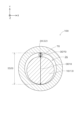
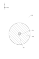
図1から図5は、第1実施形態におけるガイドワイヤ100の構成を概略的に示す説明図である。図1には、ガイドワイヤ100の縦断面(YZ断面)の構成が示されており、図2には、図1のII-IIの位置におけるガイドワイヤ100の横断面(XY断面)の構成が示されており、図3には、図1のIII-IIIの位置におけるガイドワイヤ100の横断面の構成が示されており、図4には、図1のIV-IVの位置におけるガイドワイヤ100の横断面の構成が示されており、図5には、図1のV-Vの位置におけるガイドワイヤ100の横断面の構成が示されている。なお、図1では、ガイドワイヤ100の一部分の図示が省略されている。図1において、Z軸正方向側が、体内に挿入される先端側(遠位側)であり、Z軸負方向側が、医師等の手技者によって操作される基端側(近位側)である。図1では、ガイドワイヤ100が全体としてZ軸方向に略平行な直線状となった状態を示しているが、ガイドワイヤ100の少なくとも一部の構成は、湾曲させることができる程度の可撓性を有している。本明細書では、ガイドワイヤ100およびその各構成部材について、先端側の端を「先端」といい、先端およびその近傍を「先端部」といい、基端側の端を「基端」といい、基端およびその近傍を「基端部」という。 A. First embodiment:
A-1. Configuration of guidewire 100:
1 to 5 are explanatory diagrams schematically showing the configuration of theguidewire 100 according to the first embodiment. 1 shows the configuration of the longitudinal section (YZ section) of the guidewire 100, and FIG. 2 shows the configuration of the transverse section (XY section) of the guidewire 100 at the position II-II in FIG. 3 shows the cross-sectional configuration of guidewire 100 at position III-III of FIG. 1, and FIG. 4 shows guidewire 100 at position IV-IV of FIG. , and FIG. 5 shows the cross-sectional configuration of guidewire 100 at position VV of FIG. 1, illustration of part of the guide wire 100 is omitted. In FIG. 1, the Z-axis positive direction side is the tip side (distal side) inserted into the body, and the Z-axis negative direction side is the proximal side (proximal side) operated by an operator such as a doctor. . Although FIG. 1 shows the guidewire 100 as a whole in a straight line substantially parallel to the Z-axis direction, at least a portion of the guidewire 100 is flexible enough to be curved. have. As used herein, the distal end of the guidewire 100 and its components is referred to as the "distal end," the distal end and its vicinity as the "distal portion," and the proximal end as the "proximal end." , the base end and the vicinity thereof are referred to as the “base end portion”.
A-1.ガイドワイヤ100の構成:
図1から図5は、第1実施形態におけるガイドワイヤ100の構成を概略的に示す説明図である。図1には、ガイドワイヤ100の縦断面(YZ断面)の構成が示されており、図2には、図1のII-IIの位置におけるガイドワイヤ100の横断面(XY断面)の構成が示されており、図3には、図1のIII-IIIの位置におけるガイドワイヤ100の横断面の構成が示されており、図4には、図1のIV-IVの位置におけるガイドワイヤ100の横断面の構成が示されており、図5には、図1のV-Vの位置におけるガイドワイヤ100の横断面の構成が示されている。なお、図1では、ガイドワイヤ100の一部分の図示が省略されている。図1において、Z軸正方向側が、体内に挿入される先端側(遠位側)であり、Z軸負方向側が、医師等の手技者によって操作される基端側(近位側)である。図1では、ガイドワイヤ100が全体としてZ軸方向に略平行な直線状となった状態を示しているが、ガイドワイヤ100の少なくとも一部の構成は、湾曲させることができる程度の可撓性を有している。本明細書では、ガイドワイヤ100およびその各構成部材について、先端側の端を「先端」といい、先端およびその近傍を「先端部」といい、基端側の端を「基端」といい、基端およびその近傍を「基端部」という。 A. First embodiment:
A-1. Configuration of guidewire 100:
1 to 5 are explanatory diagrams schematically showing the configuration of the
ガイドワイヤ100は、生体管腔内に挿入される長尺状医療用機器である。ガイドワイヤ100の全長は、例えば1500mm~3200mm程度である。本実施形態のガイドワイヤ100は、光ファイバ70を利用することにより、X線照射を行うことなくガイドワイヤ100の位置や形状をリアルタイムで特定して画像化するFORS機能を有している。ガイドワイヤ100は、単独で、あるいは他の画像化手法(例えば、CTやMRI)と併用されて、ガイドワイヤ100自身やガイドワイヤ100が挿入された生体管腔の位置や形状を特定するために用いられる。また、ガイドワイヤ100は、カテーテル等の併用デバイスを案内するために用いられてもよい。
The guidewire 100 is an elongated medical device that is inserted into a biological lumen. The total length of the guide wire 100 is, for example, approximately 1500 mm to 3200 mm. The guide wire 100 of the present embodiment has a FORS function that uses the optical fiber 70 to identify and image the position and shape of the guide wire 100 in real time without X-ray irradiation. The guidewire 100 is used alone or in combination with other imaging techniques (for example, CT and MRI) to identify the position and shape of the guidewire 100 itself and the biological lumen into which the guidewire 100 is inserted. Used. Guidewire 100 may also be used to guide companion devices such as catheters.
ガイドワイヤ100は、コアシャフト10と、基端側筒状体60と、外側筒状体20と、内側筒状体40と、光ファイバ70とを備える。
The guidewire 100 includes a core shaft 10 , a proximal tubular body 60 , an outer tubular body 20 , an inner tubular body 40 and an optical fiber 70 .
コアシャフト10は、ガイドワイヤ100の中心軸に沿って延びる長尺棒状の部材である。コアシャフト10の各位置における横断面の形状は、任意の形状を取り得るが、例えば略円形である。
The core shaft 10 is a long rod-shaped member extending along the central axis of the guide wire 100 . The shape of the cross section at each position of the core shaft 10 can take any shape, but is, for example, substantially circular.
図1から図4に示すように、コアシャフト10は、細径部11と、第1テーパー部12と、太径部13と、第2テーパー部14とを有している。細径部11は、コアシャフト10の先端部を構成し、略一定の外径を有する部分である。第1テーパー部12は、細径部11の基端側に隣接し、先端側から基端側に向けて外径が漸増するテーパー状(円錐台状)の部分である。第1テーパー部12の外径は、細径部11との境界位置において細径部11の外径と略一致しており、太径部13との境界位置において太径部13の外径と略一致している。太径部13は、第1テーパー部12の基端側に隣接し、細径部11の外径よりも大きい略一定の外径を有する部分である。第2テーパー部14は、太径部13の基端側に隣接すると共にコアシャフト10の基端部を構成し、先端側から基端側に向けて外径が漸減するテーパー状(円錐台状)の部分である。第2テーパー部14の外径は、太径部13との境界位置において太径部13の外径と略一致している。第2テーパー部14は、テーパーシャフト部の一例である。
As shown in FIGS. 1 to 4, the core shaft 10 has a small diameter portion 11, a first tapered portion 12, a large diameter portion 13, and a second tapered portion . The small diameter portion 11 constitutes the tip portion of the core shaft 10 and has a substantially constant outer diameter. The first tapered portion 12 is adjacent to the proximal side of the small diameter portion 11 and is a tapered (frustum-shaped) portion in which the outer diameter gradually increases from the distal end side to the proximal end side. The outer diameter of the first tapered portion 12 substantially matches the outer diameter of the small diameter portion 11 at the boundary position with the small diameter portion 11, and the outer diameter of the large diameter portion 13 at the boundary position with the large diameter portion 13. Almost match. The large-diameter portion 13 is adjacent to the proximal end side of the first taper portion 12 and has a substantially constant outer diameter larger than the outer diameter of the small-diameter portion 11 . The second tapered portion 14 is adjacent to the proximal side of the large-diameter portion 13 and constitutes the proximal end portion of the core shaft 10, and has a tapered shape (truncated cone shape) in which the outer diameter gradually decreases from the distal end side to the proximal end side. ). The outer diameter of the second tapered portion 14 substantially matches the outer diameter of the large diameter portion 13 at the boundary position with the large diameter portion 13 . The second tapered portion 14 is an example of a tapered shaft portion.
図1および図5に示すように、基端側筒状体60は、コアシャフト10より基端側に配置され、光ファイバ用ルーメン62を有する筒状部材である。基端側筒状体60は、均一の横断面を有する管体により構成されている。基端側筒状体60の横断面の形状は、任意の形状を取り得るが、例えば略円環状である。光ファイバ用ルーメン62は、例えば、ガイドワイヤ100の中心軸と同軸となる位置に形成されている。基端側筒状体60は、第1筒状体の一例であり、光ファイバ用ルーメン62は、第1ルーメンの一例である。
As shown in FIGS. 1 and 5, the proximal side tubular body 60 is a tubular member that is disposed proximal to the core shaft 10 and has an optical fiber lumen 62 . The base-side cylindrical body 60 is configured by a tubular body having a uniform cross section. The shape of the cross section of the proximal-side cylindrical body 60 can take any shape, but is, for example, substantially annular. The optical fiber lumen 62 is formed, for example, at a position coaxial with the central axis of the guide wire 100 . The proximal-side tubular body 60 is an example of a first tubular body, and the optical fiber lumen 62 is an example of a first lumen.
光ファイバ70は、上述したFORSを実現するために光信号を伝送する線状部材である。図1から図5に示すように、光ファイバ70は、基端側筒状体60の光ファイバ用ルーメン62を通り、コアシャフト10の外周面に沿ってコアシャフト10の先端側に向かって延伸している。より詳細には、光ファイバ70は、コアシャフト10の略全長にわたって(第2テーパー部14、太径部13、第1テーパー部12および細径部11にわたって)、コアシャフト10の外周面に沿って屈曲しつつ、基端側から先端側に向けて延伸している。コアシャフト10の周方向に沿った光ファイバ70の位置は、コアシャフト10の延伸方向に沿った各位置において互いに同一である。すなわち、コアシャフト10を所定の方向(図1の例ではY軸方向)から見たときに、光ファイバ70は略一直線上に延伸している。
The optical fiber 70 is a linear member that transmits optical signals to realize the FORS described above. As shown in FIGS. 1 to 5 , the optical fiber 70 passes through the optical fiber lumen 62 of the proximal tubular body 60 and extends along the outer peripheral surface of the core shaft 10 toward the distal end of the core shaft 10 . are doing. More specifically, the optical fiber 70 extends along the outer peripheral surface of the core shaft 10 over substantially the entire length of the core shaft 10 (over the second tapered portion 14, the large diameter portion 13, the first tapered portion 12, and the small diameter portion 11). It extends from the proximal side toward the distal side while bending at the bottom. The positions of the optical fibers 70 along the circumferential direction of the core shaft 10 are the same at each position along the extending direction of the core shaft 10 . That is, when the core shaft 10 is viewed from a predetermined direction (the Y-axis direction in the example of FIG. 1), the optical fiber 70 extends substantially straight.
光ファイバ70は、例えば接着剤により、コアシャフト10の例えば先端部(細径部11)および基端部(第2テーパー部14)に接合されている。また、光ファイバ70における基端側筒状体60より基端側の部分は、光ファイバ70を介したレーザ光の送受信や、反射光に基づく光ファイバ70の歪みの測定、歪みに基づく画像化等の制御を行う制御装置(不図示)に接続されている。
The optical fiber 70 is joined to, for example, the distal end portion (small diameter portion 11) and the proximal end portion (second taper portion 14) of the core shaft 10 by, for example, an adhesive. In addition, the portion of the optical fiber 70 closer to the proximal end than the proximal-side cylindrical body 60 is used for transmission and reception of laser light via the optical fiber 70, measurement of distortion of the optical fiber 70 based on reflected light, and imaging based on the distortion. It is connected to a control device (not shown) that controls such as.
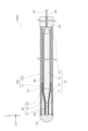
図1から図4に示すように、外側筒状体20は、コアシャフト10および光ファイバ70を覆うように、コアシャフト10および光ファイバ70の外周に配置された筒状の部材である。外側筒状体20は、先端外側筒状体21と、基端外側筒状体22とを有している。外側筒状体20は、第3筒状体の一例である。
As shown in FIGS. 1 to 4, the outer tubular body 20 is a tubular member arranged around the core shaft 10 and the optical fiber 70 so as to cover the core shaft 10 and the optical fiber 70 . The outer tubular body 20 has a distal outer tubular body 21 and a proximal outer tubular body 22 . The outer tubular body 20 is an example of a third tubular body.
先端外側筒状体21は、外側筒状体20の先端部を構成し、コアシャフト10の細径部11と、第1テーパー部12と、太径部13における先端側の一部とを覆っている。先端外側筒状体21は、線材を螺旋状に巻回することにより形成されたコイル体により構成されている。先端外側筒状体21は、単コイルであってもよいし、撚線コイルであってもよい。また、先端外側筒状体21は、疎巻きコイルであってもよいし、密巻きコイルであってもよい。
The distal outer cylindrical body 21 constitutes the distal end portion of the outer cylindrical body 20 and covers the small diameter portion 11 of the core shaft 10, the first tapered portion 12, and part of the large diameter portion 13 on the distal side. ing. The tip outer cylindrical body 21 is configured by a coil body formed by spirally winding a wire rod. The distal outer cylindrical body 21 may be a single coil or a stranded coil. Further, the tip outer cylindrical body 21 may be a loosely wound coil or a tightly wound coil.
基端外側筒状体22は、先端外側筒状体21の基端側に隣接すると共に外側筒状体20の基端部を構成し、コアシャフト10の太径部13における基端側の一部と、第2テーパー部14とを覆っている。基端外側筒状体22は、均一の横断面を有する管体により構成されている。基端外側筒状体22は、その先端部において、先端外側筒状体21の基端部と、例えば溶接により接合されている。また、基端外側筒状体22は、その基端部において、基端側筒状体60の先端部と、例えば溶接により接合されている。
The proximal outer tubular body 22 is adjacent to the proximal end of the distal outer tubular body 21 and constitutes the proximal end of the outer tubular body 20 , and is located at one end on the proximal side of the large diameter portion 13 of the core shaft 10 . and the second tapered portion 14 . Proximal outer tubular body 22 comprises a tubular body having a uniform cross-section. The proximal outer tubular body 22 is joined at its distal end to the proximal end of the distal outer tubular body 21 by, for example, welding. The proximal outer tubular body 22 is joined at its proximal end to the distal end of the proximal tubular body 60 by, for example, welding.
図3に示すように、外側筒状体20の基端外側筒状体22における内径ID20は、コアシャフト10の太径部13の外径OD10と光ファイバ70の外径OD70との和に略一致している。そのため、外側筒状体20の基端外側筒状体22の内周面とコアシャフト10の太径部13の外周面との間に形成される空間26が最小化されている。
As shown in FIG. 3, the inner diameter ID20 of the proximal outer tubular body 22 of the outer tubular body 20 is approximately the sum of the outer diameter OD10 of the large-diameter portion 13 of the core shaft 10 and the outer diameter OD70 of the optical fiber 70. Match. Therefore, the space 26 formed between the inner peripheral surface of the proximal outer tubular body 22 of the outer tubular body 20 and the outer peripheral surface of the large-diameter portion 13 of the core shaft 10 is minimized.
図1に示すように、外側筒状体20(先端外側筒状体21)の先端は、先端接合部50によって、コアシャフト10の先端と接合されている。なお、外側筒状体20とコアシャフト10とが、さらに他の箇所(例えば、先端外側筒状体21と基端外側筒状体22との接合箇所付近)において互いに接合されていてもよい。また、外側筒状体20とコアシャフト10との接合箇所において、光ファイバ70も一緒に接合されていてもよい。
As shown in FIG. 1 , the distal end of the outer cylindrical body 20 (the distal outer cylindrical body 21 ) is joined to the distal end of the core shaft 10 by a tip joining portion 50 . Note that the outer tubular body 20 and the core shaft 10 may be joined to each other at another location (for example, near the junction between the distal outer tubular body 21 and the proximal outer tubular body 22). Further, the optical fiber 70 may also be joined together at the joint between the outer cylindrical body 20 and the core shaft 10 .
図1および図2に示すように、内側筒状体40は、コアシャフト10の先端部および光ファイバ70の先端部を覆うように、コアシャフト10および光ファイバ70の外周に配置された筒状の部材である。より詳細には、内側筒状体40は、コアシャフト10の細径部11と、第1テーパー部12と、太径部13における先端側の一部とを覆っている。内側筒状体40の先端は、先端接合部50によって、コアシャフト10の先端および外側筒状体20の先端と接合されている。内側筒状体40は、線材を螺旋状に巻回することにより形成されたコイル体により構成されている。内側筒状体40は、単コイルであってもよいし、撚線コイルであってもよい。また、内側筒状体40は、疎巻きコイルであってもよいし、密巻きコイルであってもよい。内側筒状体40は、第2筒状体の一例である。
As shown in FIGS. 1 and 2, the inner tubular body 40 is a tubular body arranged around the core shaft 10 and the optical fiber 70 so as to cover the tip of the core shaft 10 and the tip of the optical fiber 70 . is a member of More specifically, the inner tubular body 40 covers the small-diameter portion 11 of the core shaft 10 , the first tapered portion 12 , and part of the large-diameter portion 13 on the distal end side. The distal end of the inner tubular body 40 is joined to the distal end of the core shaft 10 and the distal end of the outer tubular body 20 by a tip joint portion 50 . The inner cylindrical body 40 is composed of a coil body formed by spirally winding a wire. The inner tubular body 40 may be a single coil or a stranded coil. Also, the inner cylindrical body 40 may be a loosely wound coil or a tightly wound coil. The inner tubular body 40 is an example of a second tubular body.
内側筒状体40は、細径部41と、テーパー部42と、太径部43とを有している。内側筒状体40の細径部41は、内側筒状体40の先端部を構成し、略一定の内径および外径を有し、コアシャフト10の細径部11を覆う部分である。内側筒状体40のテーパー部42は、細径部41の基端側に隣接し、先端側から基端側に向けて内径および外径が漸増するテーパー状(中空円錐台状)であり、コアシャフト10の第1テーパー部12を覆う部分である。内側筒状体40の太径部43は、テーパー部42の基端側に隣接し、細径部41の内径および外径よりも大きい略一定の内径および外径を有し、コアシャフト10の太径部13を覆う部分である。
The inner tubular body 40 has a small diameter portion 41 , a tapered portion 42 and a large diameter portion 43 . The narrow diameter portion 41 of the inner tubular body 40 constitutes the distal end portion of the inner tubular body 40 , has a substantially constant inner diameter and outer diameter, and is a portion that covers the narrow diameter portion 11 of the core shaft 10 . The tapered portion 42 of the inner cylindrical body 40 is adjacent to the proximal end side of the small diameter portion 41 and has a tapered shape (hollow truncated cone shape) in which the inner diameter and outer diameter gradually increase from the distal end side to the proximal end side, It is a portion that covers the first tapered portion 12 of the core shaft 10 . The large-diameter portion 43 of the inner cylindrical body 40 is adjacent to the proximal end side of the tapered portion 42 and has substantially constant inner and outer diameters larger than the inner and outer diameters of the small-diameter portion 41 . It is a portion that covers the large-diameter portion 13 .
図1および図2に示すように、内側筒状体40の延伸方向に沿った各位置において、内側筒状体40の内径ID40は、コアシャフト10の外径OD10と光ファイバ70の外径OD70との和に略一致している。そのため、内側筒状体40の内周面は光ファイバ70に接しており、その結果、内側筒状体40によって光ファイバ70がコアシャフト10の外周面から離隔することが規制されている。なお、上記内径および外径の関係が成立している結果、内側筒状体40の細径部41およびテーパー部42における内径ID40は、コアシャフト10の太径部13の外径OD10と光ファイバ70の外径OD70との和より小さいという関係が成り立っている。
As shown in FIGS. 1 and 2, the inner diameter ID40 of the inner tubular body 40 is equal to the outer diameter OD10 of the core shaft 10 and the outer diameter OD70 of the optical fiber 70 at each position along the extending direction of the inner tubular body 40 . is approximately equal to the sum of Therefore, the inner peripheral surface of the inner tubular body 40 is in contact with the optical fiber 70 , and as a result, the inner tubular body 40 restricts the separation of the optical fiber 70 from the outer peripheral surface of the core shaft 10 . As a result of the relationship between the inner diameter and the outer diameter being established, the inner diameter ID40 of the small-diameter portion 41 and the tapered portion 42 of the inner cylindrical body 40 is the same as the outer diameter OD10 of the large-diameter portion 13 of the core shaft 10 and the optical fiber. OD70 is smaller than the sum of OD70 and OD70.
また、図1および図2に示すように、内側筒状体40の外径OD40は、外側筒状体20(先端外側筒状体21)の内径ID20以下である。より詳細には、内側筒状体40の太径部43の位置では、内側筒状体40の外径OD40は、外側筒状体20の内径ID20に略一致し、内側筒状体40のテーパー部42および細径部41の位置では、内側筒状体40の外径OD40は、外側筒状体20の内径ID20より小さい。そのため、内側筒状体40のテーパー部42および細径部41の位置では、外側筒状体20の内周面と内側筒状体40の外周面との間に空間24が存在している。
Also, as shown in FIGS. 1 and 2, the outer diameter OD40 of the inner tubular body 40 is equal to or smaller than the inner diameter ID20 of the outer tubular body 20 (the tip outer tubular body 21). More specifically, at the position of the large-diameter portion 43 of the inner tubular body 40, the outer diameter OD40 of the inner tubular body 40 substantially matches the inner diameter ID20 of the outer tubular body 20, and the inner tubular body 40 is tapered. The outer diameter OD40 of the inner tubular body 40 is smaller than the inner diameter ID20 of the outer tubular body 20 at the positions of the portion 42 and the small diameter portion 41 . Therefore, a space 24 exists between the inner peripheral surface of the outer tubular body 20 and the outer peripheral surface of the inner tubular body 40 at the positions of the tapered portion 42 and the small diameter portion 41 of the inner tubular body 40 .
コアシャフト10、基端側筒状体60、外側筒状体20および内側筒状体40は、例えば金属により形成されており、より具体的には、例えばステンレス鋼(SUS302、SUS304、SUS316等)、Ni-Ti合金、ピアノ線等により形成されている。これらの部材の少なくとも一部が、放射線不透過材料(例えば、白金やタングステン等)により形成されていてもよい。また、先端接合部50は、例えば、金属ハンダ(Au-Sn合金、Sn-Ag合金、Sn-Pb合金、Pb-Ag合金等)、ロウ材(アルミニウム合金ロウ、銀ロウ、金ロウ等)、接着剤(エポキシ系接着剤等)等により形成されている。
The core shaft 10, the proximal side tubular body 60, the outer tubular body 20, and the inner tubular body 40 are made of metal, for example, and more specifically, stainless steel (SUS302, SUS304, SUS316, etc.). , Ni—Ti alloy, piano wire, or the like. At least part of these members may be made of a radiopaque material (for example, platinum, tungsten, etc.). In addition, the tip joint portion 50 includes, for example, metal solder (Au—Sn alloy, Sn—Ag alloy, Sn—Pb alloy, Pb—Ag alloy, etc.), brazing material (aluminum alloy brazing, silver brazing, gold brazing, etc.), It is formed of an adhesive (epoxy adhesive, etc.) or the like.
なお、ガイドワイヤ100の少なくとも一部が、親水性の樹脂コーティング層により覆われていてもよい。
At least part of the guide wire 100 may be covered with a hydrophilic resin coating layer.
A-2.本実施形態の効果:
以上説明したように、本実施形態のガイドワイヤ100は、コアシャフト10と、基端側筒状体60と、光ファイバ70とを備える。基端側筒状体60は、コアシャフト10より基端側に配置され、光ファイバ用ルーメン62を有する筒状体である。光ファイバ70は、光ファイバ用ルーメン62を通り、コアシャフト10の外周面に沿って、コアシャフト10の先端側に向かって延びている。そのため、本実施形態のガイドワイヤ100によれば、光ファイバ70を利用したガイドワイヤ100の位置および形状の特定(画像化)を実現することができる。 A-2. Effect of this embodiment:
As described above, theguidewire 100 of this embodiment includes the core shaft 10 , the proximal tubular body 60 and the optical fiber 70 . The proximal-side tubular body 60 is a tubular body that is disposed on the proximal side of the core shaft 10 and has an optical fiber lumen 62 . The optical fiber 70 passes through the optical fiber lumen 62 and extends toward the distal end side of the core shaft 10 along the outer peripheral surface of the core shaft 10 . Therefore, according to the guidewire 100 of the present embodiment, the position and shape of the guidewire 100 can be specified (imaging) using the optical fiber 70 .
以上説明したように、本実施形態のガイドワイヤ100は、コアシャフト10と、基端側筒状体60と、光ファイバ70とを備える。基端側筒状体60は、コアシャフト10より基端側に配置され、光ファイバ用ルーメン62を有する筒状体である。光ファイバ70は、光ファイバ用ルーメン62を通り、コアシャフト10の外周面に沿って、コアシャフト10の先端側に向かって延びている。そのため、本実施形態のガイドワイヤ100によれば、光ファイバ70を利用したガイドワイヤ100の位置および形状の特定(画像化)を実現することができる。 A-2. Effect of this embodiment:
As described above, the
また、本実施形態のガイドワイヤ100では、光ファイバ70が、中空筒状体ではなく、コアシャフト10によって支持されている。コアシャフト10は、中空部を有さないため、外径が同じであるとすると、中空筒状体より剛性を高くすることができる。そのため、本実施形態のガイドワイヤ100によれば、コアシャフト10の存在によってガイドワイヤ100の剛性を高くすることができ、その結果、例えばカテーテル等の併用デバイスのサポート性やガイドワイヤ100の先端部の曲げ耐久性を向上させることができる。
Also, in the guide wire 100 of this embodiment, the optical fiber 70 is supported by the core shaft 10 instead of the hollow cylindrical body. Since the core shaft 10 does not have a hollow portion, it can have higher rigidity than a hollow cylindrical body, provided that the outer diameter is the same. Therefore, according to the guidewire 100 of the present embodiment, the rigidity of the guidewire 100 can be increased by the existence of the core shaft 10, and as a result, for example, the supportability of a combined device such as a catheter and the tip portion of the guidewire 100 can be improved. can improve the bending durability of
このように、本実施形態のガイドワイヤ100によれば、光ファイバ70を利用したガイドワイヤ100の位置および形状の特定(画像化)を実現しつつ、コアシャフト10の存在によってガイドワイヤ100の剛性を高くすることができ、併用デバイスのサポート性や先端部の曲げ耐久性を向上させることができる。
As described above, according to the guidewire 100 of the present embodiment, the position and shape of the guidewire 100 can be specified (imaging) using the optical fiber 70, and the rigidity of the guidewire 100 can be reduced by the existence of the core shaft 10. can be increased, and the supportability of the combined device and the bending durability of the tip portion can be improved.
また、本実施形態のガイドワイヤ100では、コアシャフト10が第2テーパー部14を有する。第2テーパー部14は、コアシャフト10の基端部を構成し、外径が基端側に向かって漸減するテーパー状の部分である。そのため、コアシャフト10が第2テーパー部14を有さず、太径部13がコアシャフト10の基端まで至っている構成と比較して、光ファイバ70がコアシャフト10の基端部の外周面から基端側筒状体60の光ファイバ用ルーメン62に至る経路において、光ファイバ70が90度程度の大きな角度で屈折する箇所を減らすことができる。従って、本実施形態のガイドワイヤ100によれば、光ファイバ70の破断のリスクを低減することができる。
Further, in the guidewire 100 of this embodiment, the core shaft 10 has the second tapered portion 14 . The second tapered portion 14 constitutes the proximal end portion of the core shaft 10 and is a tapered portion in which the outer diameter gradually decreases toward the proximal end side. Therefore, compared to the configuration in which the core shaft 10 does not have the second tapered portion 14 and the large-diameter portion 13 extends to the proximal end of the core shaft 10 , the optical fiber 70 is to the optical fiber lumen 62 of the proximal side cylindrical body 60, the number of locations where the optical fiber 70 is bent at a large angle of about 90 degrees can be reduced. Therefore, according to the guide wire 100 of this embodiment, the risk of breakage of the optical fiber 70 can be reduced.
また、本実施形態のガイドワイヤ100では、コアシャフト10は、太径部13と、太径部13より先端側に位置し、太径部13より外径が小さい細径部11とを有する。また、ガイドワイヤ100は、さらに内側筒状体40を備える。内側筒状体40は、少なくともコアシャフト10の細径部11と光ファイバ70の先端部とを覆っている。内側筒状体40におけるコアシャフト10の細径部11を覆う部分(内側筒状体40の細径部41)の内径は、コアシャフト10の太径部13の外径と光ファイバ70の外径との和より小さい。そのため、コアシャフト10の太径部13の外周面に沿って先端側に延びる光ファイバ70が、コアシャフト10の細径部11に対向する位置において、内側筒状体40の内周面によってコアシャフト10に近付くように押さえられる。従って、本実施形態のガイドワイヤ100によれば、内側筒状体40の存在によってコアシャフト10の変形時における光ファイバ70の追従性を高めることができ、光ファイバ70を利用したガイドワイヤ100の位置および形状の特定(画像化)の精度を向上させることができる。
In addition, in the guidewire 100 of the present embodiment, the core shaft 10 has the large diameter portion 13 and the small diameter portion 11 positioned distally of the large diameter portion 13 and having an outer diameter smaller than that of the large diameter portion 13 . Guidewire 100 also includes an inner tubular body 40 . The inner cylindrical body 40 covers at least the narrow diameter portion 11 of the core shaft 10 and the tip portion of the optical fiber 70 . The inner diameter of the portion of the inner cylindrical body 40 that covers the small diameter portion 11 of the core shaft 10 (the small diameter portion 41 of the inner cylindrical body 40) is equal to the outer diameter of the large diameter portion 13 of the core shaft 10 and the outer diameter of the optical fiber 70. Smaller than sum with diameter. Therefore, the optical fiber 70 extending toward the distal end along the outer peripheral surface of the large-diameter portion 13 of the core shaft 10 faces the small-diameter portion 11 of the core shaft 10 by the inner peripheral surface of the inner cylindrical body 40 . It is pressed so as to approach the shaft 10 . Therefore, according to the guidewire 100 of the present embodiment, the presence of the inner cylindrical body 40 can enhance the followability of the optical fiber 70 when the core shaft 10 is deformed, and the guidewire 100 using the optical fiber 70 can be improved. The accuracy of location and shape identification (imaging) can be improved.
また、本実施形態のガイドワイヤ100では、内側筒状体40の延伸方向に沿った少なくとも一部の位置において、内側筒状体40の内径ID40は、コアシャフト10の外径OD10と光ファイバ70の外径OD70との和に一致する。そのため、本実施形態のガイドワイヤ100によれば、内側筒状体40の存在によって光ファイバ70がコアシャフト10に接する状態を維持することができ、コアシャフト10の変形時における光ファイバ70の追従性を効果的に高めることができ、光ファイバ70を利用したガイドワイヤ100の位置および形状の特定(画像化)の精度を効果的に向上させることができる。
Further, in the guidewire 100 of the present embodiment, the inner diameter ID40 of the inner tubular body 40 is equal to the outer diameter OD10 of the core shaft 10 and the optical fiber 70 at at least some positions along the extending direction of the inner tubular body 40. and the sum of the outer diameter OD70. Therefore, according to the guide wire 100 of the present embodiment, the presence of the inner cylindrical body 40 allows the optical fiber 70 to maintain contact with the core shaft 10, and the optical fiber 70 follows the deformation of the core shaft 10. It is possible to effectively improve the accuracy of identifying (imaging) the position and shape of the guide wire 100 using the optical fiber 70 .
また、本実施形態のガイドワイヤ100では、内側筒状体40はコイル体により構成されている。そのため、本実施形態のガイドワイヤ100によれば、内側筒状体40の存在によってコアシャフト10の変形時における光ファイバ70の追従性を高めつつ、ガイドワイヤ100の先端部の柔軟性が低下することを抑制することができる。
In addition, in the guidewire 100 of this embodiment, the inner cylindrical body 40 is composed of a coil body. Therefore, according to the guidewire 100 of the present embodiment, the presence of the inner cylindrical body 40 improves the followability of the optical fiber 70 when the core shaft 10 deforms, while reducing the flexibility of the distal end portion of the guidewire 100. can be suppressed.
また、本実施形態のガイドワイヤ100は、さらに、コアシャフト10と内側筒状体40と光ファイバ70とを覆う外側筒状体20を備える。そのため、本実施形態のガイドワイヤ100によれば、外側筒状体20によってコアシャフト10の外周面に沿って配置された光ファイバ70を保護することができる。
In addition, the guidewire 100 of this embodiment further includes an outer tubular body 20 that covers the core shaft 10, the inner tubular body 40, and the optical fiber 70. Therefore, according to the guidewire 100 of the present embodiment, the optical fiber 70 arranged along the outer peripheral surface of the core shaft 10 can be protected by the outer cylindrical body 20 .
また、本実施形態のガイドワイヤ100では、外側筒状体20の先端部を構成する先端外側筒状体21はコイル体により構成されている。そのため、本実施形態のガイドワイヤ100によれば、ガイドワイヤ100の先端部の柔軟性が低下することを抑制することができる。
In addition, in the guidewire 100 of the present embodiment, the distal outer tubular body 21 forming the distal end portion of the outer tubular body 20 is composed of a coil body. Therefore, according to the guidewire 100 of the present embodiment, it is possible to prevent the flexibility of the distal end portion of the guidewire 100 from decreasing.
また、本実施形態のガイドワイヤ100では、外側筒状体20の基端部を構成する基端外側筒状体22は金属管体により構成されている。そのため、ガイドワイヤ100の基端部の剛性を高めることができ、ガイドワイヤ100のトルク伝達性やプッシャビリティを向上させることができる。
In addition, in the guidewire 100 of the present embodiment, the proximal outer tubular body 22 forming the proximal end portion of the outer tubular body 20 is made of a metal tubular body. Therefore, the rigidity of the proximal end portion of the guidewire 100 can be increased, and the torque transmissibility and pushability of the guidewire 100 can be improved.
B.第2実施形態:
図6は、第2実施形態におけるガイドワイヤ100aの構成を概略的に示す説明図である。図6には、ガイドワイヤ100aの縦断面の構成が示されている。以下では、第2実施形態のガイドワイヤ100aの構成の内、上述した第1実施形態のガイドワイヤ100と同一の構成については、同一の符号を付すことによってその説明を適宜省略する。 B. Second embodiment:
FIG. 6 is an explanatory diagram schematically showing the configuration of the guidewire 100a in the second embodiment. FIG. 6 shows the configuration of a longitudinal section of the guidewire 100a. In the following, among the configurations of theguidewire 100a of the second embodiment, the same configurations as those of the guidewire 100 of the first embodiment described above are denoted by the same reference numerals, and description thereof will be omitted as appropriate.
図6は、第2実施形態におけるガイドワイヤ100aの構成を概略的に示す説明図である。図6には、ガイドワイヤ100aの縦断面の構成が示されている。以下では、第2実施形態のガイドワイヤ100aの構成の内、上述した第1実施形態のガイドワイヤ100と同一の構成については、同一の符号を付すことによってその説明を適宜省略する。 B. Second embodiment:
FIG. 6 is an explanatory diagram schematically showing the configuration of the guidewire 100a in the second embodiment. FIG. 6 shows the configuration of a longitudinal section of the guidewire 100a. In the following, among the configurations of the
第2実施形態のガイドワイヤ100aは、外側筒状体20aの構成が、第1実施形態のガイドワイヤ100と異なる。具体的には、第2実施形態のガイドワイヤ100aでは、外側筒状体20aの基端外側筒状体22aが、管体ではなく、コイル体より構成されている。すなわち、外側筒状体20aが全長にわたってコイル体により形成されている。
The guidewire 100a of the second embodiment differs from the guidewire 100 of the first embodiment in the configuration of the outer tubular body 20a. Specifically, in the guidewire 100a of the second embodiment, the proximal outer cylindrical body 22a of the outer cylindrical body 20a is not a tubular body but a coiled body. That is, the outer cylindrical body 20a is formed of a coil body over its entire length.
なお、本実施形態では、外側筒状体20aが、先端外側筒状体21および基端外側筒状体22aという2つのコイル体が接合された構成を有するが、外側筒状体20aが単一のコイル体により構成されてもよい。
In the present embodiment, the outer tubular body 20a has a configuration in which two coil bodies, the distal outer tubular body 21 and the proximal outer tubular body 22a, are joined together, but the outer tubular body 20a is a single body. may be configured by a coil body of
第2実施形態のガイドワイヤ100aによれば、第1実施形態のガイドワイヤ100と同様に、光ファイバ70を利用したガイドワイヤ100aの位置および形状の特定(画像化)を実現しつつ、コアシャフト10の存在によってガイドワイヤ100aの剛性を高くすることができ、併用デバイスのサポート性や先端部の曲げ耐久性を高くすることができる。
According to the guidewire 100a of the second embodiment, as with the guidewire 100 of the first embodiment, the position and shape of the guidewire 100a can be specified (imaging) using the optical fiber 70, while the core shaft The presence of 10 can increase the rigidity of the guide wire 100a, thereby increasing the supportability of the combined device and the bending durability of the distal end.
また、第2実施形態のガイドワイヤ100aによれば、外側筒状体20aが全長にわたってコイル体により形成されているため、ガイドワイヤ100aの剛性ギャップを低減して耐キンク性を向上させることができる。
Further, according to the guidewire 100a of the second embodiment, since the outer cylindrical body 20a is formed of the coil body over the entire length, it is possible to reduce the rigidity gap of the guidewire 100a and improve the kink resistance. .
C.第3実施形態:
図7から図9は、第3実施形態におけるガイドワイヤ100bの構成を概略的に示す説明図である。図7には、ガイドワイヤ100bの縦断面の構成が示されており、図8には、図7のVIII-VIIIの位置におけるガイドワイヤ100bの横断面の構成が示されており、図9には、図7のIX-IXの位置におけるガイドワイヤ100bの横断面の構成が示されている。以下では、第3実施形態のガイドワイヤ100bの構成の内、上述した第1実施形態のガイドワイヤ100と同一の構成については、同一の符号を付すことによってその説明を適宜省略する。 C. Third embodiment:
7 to 9 are explanatory diagrams schematically showing the configuration of theguidewire 100b in the third embodiment. 7 shows the configuration of the longitudinal section of the guidewire 100b, FIG. 8 shows the configuration of the cross section of the guidewire 100b at the position VIII-VIII in FIG. 7, and FIG. 7 shows the cross-sectional configuration of guidewire 100b at position IX-IX in FIG. In the following, among the configurations of the guidewire 100b of the third embodiment, the same configurations as those of the guidewire 100 of the first embodiment described above are denoted by the same reference numerals, and description thereof will be omitted as appropriate.
図7から図9は、第3実施形態におけるガイドワイヤ100bの構成を概略的に示す説明図である。図7には、ガイドワイヤ100bの縦断面の構成が示されており、図8には、図7のVIII-VIIIの位置におけるガイドワイヤ100bの横断面の構成が示されており、図9には、図7のIX-IXの位置におけるガイドワイヤ100bの横断面の構成が示されている。以下では、第3実施形態のガイドワイヤ100bの構成の内、上述した第1実施形態のガイドワイヤ100と同一の構成については、同一の符号を付すことによってその説明を適宜省略する。 C. Third embodiment:
7 to 9 are explanatory diagrams schematically showing the configuration of the
第3実施形態のガイドワイヤ100bは、コアシャフト10bの構成が、第1実施形態のガイドワイヤ100と異なる。具体的には、第3実施形態のガイドワイヤ100bでは、コアシャフト10bの太径部13bがコアシャフト10bの基端部を構成しており、第1実施形態における第2テーパー部14のような部分が存在しない。
The guidewire 100b of the third embodiment differs from the guidewire 100 of the first embodiment in the configuration of the core shaft 10b. Specifically, in the guidewire 100b of the third embodiment, the large-diameter portion 13b of the core shaft 10b constitutes the base end portion of the core shaft 10b, and is like the second tapered portion 14 of the first embodiment. part does not exist.
また、第3実施形態のガイドワイヤ100bでは、コアシャフト10bにおける太径部13bの外周面に溝18が形成されている。溝18は、太径部13bの全長にわたって形成されている。コアシャフト10bの周方向に沿った溝18の位置は、コアシャフト10bの延伸方向に沿った各位置において互いに同一である。すなわち、コアシャフト10bを所定の方向(図7の例ではY軸方向)から見たときに、溝18は略一直線上に延伸している。
Further, in the guide wire 100b of the third embodiment, a groove 18 is formed in the outer peripheral surface of the large-diameter portion 13b of the core shaft 10b. The groove 18 is formed over the entire length of the large-diameter portion 13b. The positions of the grooves 18 along the circumferential direction of the core shaft 10b are the same at each position along the extending direction of the core shaft 10b. That is, when the core shaft 10b is viewed from a predetermined direction (the Y-axis direction in the example of FIG. 7), the grooves 18 extend substantially straight.
溝18の深さは、太径部13bの先端から基端部付近まで略一定であり、より具体的には、光ファイバ70の外径OD70に略一致している。ただし、太径部13bの基端部において、溝18は、深さが基端側に向かって漸増するテーパー溝部19を有する(図7および図9)。テーパー溝部19においては、溝18の深さは光ファイバ70の外径OD70より大きい。
The depth of the groove 18 is substantially constant from the tip of the large-diameter portion 13 b to the vicinity of the base end, and more specifically, substantially matches the outer diameter OD70 of the optical fiber 70 . However, at the proximal end portion of the large-diameter portion 13b, the groove 18 has a tapered groove portion 19 whose depth gradually increases toward the proximal end side (FIGS. 7 and 9). In tapered groove portion 19 , the depth of groove 18 is greater than outer diameter OD 70 of optical fiber 70 .
コアシャフト10bの太径部13bに形成された溝18には、光ファイバ70が収容されている。上述したように、溝18の深さは、太径部13bの先端から基端部付近まで、光ファイバ70の外径OD70に略一致しているため、光ファイバ70の横断面の略全体が溝18内に収容される。そのため、図8に示すように、ガイドワイヤ100bの横断面において、光ファイバ70は、コアシャフト10bの太径部13bの略円形の横断面の内側に配置される。なお、外側筒状体20の基端外側筒状体22における内径ID20は、コアシャフト10bの太径部13bの外径OD10と略一致している。そのため、基端外側筒状体22の内周面とコアシャフト10bの太径部13bの外周面との間にはほとんど空間が存在しない。
An optical fiber 70 is accommodated in a groove 18 formed in the large-diameter portion 13b of the core shaft 10b. As described above, the depth of the groove 18 substantially matches the outer diameter OD70 of the optical fiber 70 from the distal end of the large-diameter portion 13b to the vicinity of the proximal end. It is housed in groove 18 . Therefore, as shown in FIG. 8, in the cross section of the guide wire 100b, the optical fiber 70 is arranged inside the substantially circular cross section of the large diameter portion 13b of the core shaft 10b. The inner diameter ID20 of the base end outer tubular body 22 of the outer tubular body 20 substantially matches the outer diameter OD10 of the large diameter portion 13b of the core shaft 10b. Therefore, there is almost no space between the inner peripheral surface of the proximal outer cylindrical body 22 and the outer peripheral surface of the large diameter portion 13b of the core shaft 10b.
また、図7および図9に示すように、溝18のテーパー溝部19においては、溝18の深さが光ファイバ70の外径OD70より大きいため、光ファイバ70は、溝18の底面に沿ってコアシャフト10bの中心軸に近付くように延伸する。なお、コアシャフト10bの第1テーパー部12および細径部11には溝18が形成されていないため、この位置では図3に示すように、光ファイバ70はコアシャフト10bの略円形の横断面の外側に配置される。
7 and 9, in the tapered groove portion 19 of the groove 18, since the depth of the groove 18 is greater than the outer diameter OD70 of the optical fiber 70, the optical fiber 70 extends along the bottom surface of the groove 18. It extends so as to approach the central axis of the core shaft 10b. Since the grooves 18 are not formed in the first taper portion 12 and the small diameter portion 11 of the core shaft 10b, the optical fiber 70 at this position has a substantially circular cross section of the core shaft 10b as shown in FIG. placed outside the
以上説明したように、第3実施形態のガイドワイヤ100bでは、コアシャフト10bの外周面に、コアシャフト10bの基端から先端側に延びる溝18が形成されており、光ファイバ70の延伸方向に沿った少なくとも一部は溝18内に収容されている。そのため、第3実施形態のガイドワイヤ100bによれば、コアシャフト10bの外周面上における光ファイバ70の位置の固定性を高めることができ、これにより、コアシャフト10bの変形時における光ファイバ70の追従性を高めることができ、光ファイバ70を利用したガイドワイヤ100bの位置および形状の特定(画像化)の精度を向上させることができる。また、光ファイバ70が溝18内に収容されているため、ガイドワイヤ100bの基端部において、コアシャフト10bと外側筒状体20との間に形成される空間を小さくすることができ、該空間の存在に起因するガイドワイヤ100bの剛性の低下を抑制することができる。
As described above, in the guidewire 100b of the third embodiment, the groove 18 extending from the proximal end of the core shaft 10b to the distal side is formed in the outer peripheral surface of the core shaft 10b, and the groove 18 extends in the extending direction of the optical fiber 70. At least a portion along is housed within groove 18 . Therefore, according to the guide wire 100b of the third embodiment, it is possible to improve the fixability of the position of the optical fiber 70 on the outer peripheral surface of the core shaft 10b, thereby allowing the optical fiber 70 to move when the core shaft 10b is deformed. Trackability can be improved, and the accuracy of specifying (imaging) the position and shape of the guide wire 100b using the optical fiber 70 can be improved. Further, since the optical fiber 70 is accommodated in the groove 18, the space formed between the core shaft 10b and the outer cylindrical body 20 can be reduced at the proximal end of the guide wire 100b. A reduction in rigidity of the guidewire 100b due to the existence of the space can be suppressed.
また、第3実施形態のガイドワイヤ100bでは、コアシャフト10bの基端部において、溝18は、深さが基端側に向かって漸増するテーパー溝部19を有する。そのため、溝18がテーパー溝部19を有さず、溝18の深さが溝18の基端まで一定である構成と比較して、光ファイバ70が90度程度の大きな角度で屈折する箇所を減らすことができ、光ファイバ70の破断のリスクを低減することができる。また、溝18をテーパー形状にするだけでよく、コアシャフト10b自身をテーパー形状とする必要がないため、コアシャフト10bの剛性低下、ひいてはガイドワイヤ100bの剛性低下を抑制することができる。
Further, in the guidewire 100b of the third embodiment, the groove 18 has a tapered groove portion 19 whose depth gradually increases toward the proximal end at the proximal end portion of the core shaft 10b. Therefore, compared with the configuration in which the groove 18 does not have the tapered groove portion 19 and the depth of the groove 18 is constant up to the base end of the groove 18, the number of places where the optical fiber 70 is bent at a large angle of about 90 degrees is reduced. , and the risk of breakage of the optical fiber 70 can be reduced. Moreover, since it is only necessary to form the groove 18 into a tapered shape, and the core shaft 10b itself does not need to be formed into a tapered shape, it is possible to suppress a reduction in rigidity of the core shaft 10b and, in turn, a reduction in rigidity of the guide wire 100b.
D.変形例:
本明細書で開示される技術は、上述の実施形態に限られるものではなく、その要旨を逸脱しない範囲において種々の形態に変形することができ、例えば次のような変形も可能である。 D. Variant:
The technology disclosed in this specification is not limited to the above-described embodiments, and can be modified in various forms without departing from the scope of the invention. For example, the following modifications are possible.
上記実施形態におけるガイドワイヤ100の構成は、あくまで一例であり、種々変形可能である。例えば、上記第1実施形態では、コアシャフト10が、細径部11と第1テーパー部12と太径部13と第2テーパー部14とから構成されているが、コアシャフト10は、これら4つの部分の内の少なくとも1つを有さないとしてもよいし、該4つの部分の他に他の部分を有するとしてもよい。例えば、コアシャフト10が第2テーパー部14を有さなくてもよい。他の実施形態におけるコアシャフト10についても同様である。
The configuration of the guide wire 100 in the above embodiment is merely an example, and various modifications are possible. For example, in the first embodiment, the core shaft 10 is composed of the small diameter portion 11, the first tapered portion 12, the large diameter portion 13, and the second tapered portion 14. At least one of the four portions may not be included, or other portions may be included in addition to the four portions. For example, the core shaft 10 does not have to have the second tapered portion 14 . The same applies to core shafts 10 in other embodiments.
上記実施形態では、コアシャフト10の周方向に沿った光ファイバ70の位置は、コアシャフト10の延伸方向に沿った各位置において互いに同一であるが、コアシャフト10の周方向に沿った光ファイバ70の位置は、コアシャフト10の延伸方向に沿った各位置において異なっていてもよい。例えば、光ファイバ70がコアシャフト10に対して螺旋状に巻回されるように配置されていてもよい。
In the above embodiment, the positions of the optical fibers 70 along the circumferential direction of the core shaft 10 are the same at each position along the extending direction of the core shaft 10, but the optical fibers 70 along the circumferential direction of the core shaft 10 The position of 70 may be different at each position along the extension direction of core shaft 10 . For example, the optical fiber 70 may be arranged so as to be spirally wound around the core shaft 10 .
上記第3実施形態において、溝18は、コアシャフト10bの太径部13bの全長にわたって形成されているが、溝18が太径部13bの一部のみに形成されていてもよい。また、溝18がテーパー溝部19を有さなくてもよい。また、溝18がコアシャフト10bにおける太径部13b以外の部分にも形成されていてもよい。また、上記第3実施形態では、コアシャフト10bの周方向に沿った溝18の位置は、コアシャフト10bの延伸方向に沿った各位置において互いに同一であるが、コアシャフト10b周方向に沿った溝18の位置は、コアシャフト10bの延伸方向に沿った各位置において異なっていてもよい。また、上記第1および第2実施形態において、第3実施形態と同様に、コアシャフト10に溝18が形成されており、溝18内に光ファイバ70が収容されていてもよい。
In the third embodiment, the groove 18 is formed over the entire length of the large diameter portion 13b of the core shaft 10b, but the groove 18 may be formed only in part of the large diameter portion 13b. Also, the groove 18 may not have the tapered groove portion 19 . Also, the groove 18 may be formed in a portion of the core shaft 10b other than the large-diameter portion 13b. Further, in the third embodiment, the positions of the grooves 18 along the circumferential direction of the core shaft 10b are the same at each position along the extension direction of the core shaft 10b. The position of the groove 18 may be different at each position along the extending direction of the core shaft 10b. Further, in the first and second embodiments described above, the groove 18 may be formed in the core shaft 10 and the optical fiber 70 may be accommodated in the groove 18 as in the third embodiment.
上記第3実施形態では、光ファイバ70のうち、太径部13bの溝18に対向する部分において、溝18内に光ファイバ70の横断面の全体が収容されているが、溝18内に横断面の一部のみが収容されてもよい。
In the third embodiment, the entire cross section of the optical fiber 70 is accommodated in the groove 18 at the portion of the optical fiber 70 facing the groove 18 of the large-diameter portion 13b. Only part of the face may be accommodated.
上記実施形態では、内側筒状体40の延伸方向に沿った各位置において、内側筒状体40の内径ID40は、コアシャフト10の外径OD10と光ファイバ70の外径OD70との和に略一致しているが、内側筒状体40の延伸方向に沿った一部または全部の位置において、内側筒状体40の内径ID40は該和より大きくてもよい。また、上記実施形態では、内側筒状体40がコイル体により構成されているが、内側筒状体40がコイル体ではなく、均一の横断面を有する管体により構成されていてもよい。
In the above embodiment, the inner diameter ID40 of the inner tubular body 40 is approximately the sum of the outer diameter OD10 of the core shaft 10 and the outer diameter OD70 of the optical fiber 70 at each position along the extending direction of the inner tubular body 40. Although consistent, the inner diameter ID 40 of the inner tubular body 40 may be greater than the sum at some or all locations along the direction of elongation of the inner tubular body 40 . In addition, in the above embodiment, the inner cylindrical body 40 is composed of a coiled body, but the inner cylindrical body 40 may be composed of a tubular body having a uniform cross section instead of the coiled body.
上記実施形態のガイドワイヤ100において、少なくとも1つの部材が省略されてもよい。例えば、上記実施形態のガイドワイヤ100において、内側筒状体40と外側筒状体20との少なくとも一方が省略されてもよい。また、上記実施形態における各部材の材料は、あくまで一例であり、種々変形可能である。
At least one member may be omitted from the guidewire 100 of the above embodiment. For example, in the guidewire 100 of the above embodiment, at least one of the inner tubular body 40 and the outer tubular body 20 may be omitted. In addition, the material of each member in the above embodiment is merely an example, and various modifications are possible.
10:コアシャフト 11:細径部 12:第1テーパー部 13:太径部 14:第2テーパー部 18:溝 19:テーパー溝部 20:外側筒状体 21:先端外側筒状体 22:基端外側筒状体 24:空間 26:空間 40:内側筒状体 41:細径部 42:テーパー部 43:太径部 50:先端接合部 60:基端側筒状体 62:光ファイバ用ルーメン 70:光ファイバ 100:ガイドワイヤ
10: Core shaft 11: Small diameter portion 12: First taper portion 13: Large diameter portion 14: Second taper portion 18: Groove 19: Taper groove portion 20: Outer cylindrical body 21: Tip outer cylindrical body 22: Base end Outer tubular body 24: Space 26: Space 40: Inner tubular body 41: Small diameter portion 42: Taper portion 43: Large diameter portion 50: Tip joint portion 60: Base end side tubular body 62: Optical fiber lumen 70 : Optical fiber 100: Guide wire
Claims (6)
- ガイドワイヤであって、
コアシャフトと、
前記コアシャフトより基端側に配置され、第1ルーメンを有する第1筒状体と、
前記第1ルーメンを通り、前記コアシャフトの外周面に沿って、前記コアシャフトの先端側に向かって延びる光ファイバと、
を備える、
ガイドワイヤ。 a guide wire,
a core shaft;
a first cylindrical body disposed proximal to the core shaft and having a first lumen;
an optical fiber that passes through the first lumen and extends toward the distal end of the core shaft along the outer peripheral surface of the core shaft;
comprising a
guide wire. - 請求項1に記載のガイドワイヤであって、
前記コアシャフトは、前記コアシャフトの基端部を構成し、外径が基端側に向かって漸減するテーパーシャフト部を有する、
ガイドワイヤ。 The guidewire of claim 1, comprising:
The core shaft has a tapered shaft portion that constitutes the base end portion of the core shaft and has an outer diameter that gradually decreases toward the base end side.
guide wire. - 請求項1または請求項2に記載のガイドワイヤであって、
前記コアシャフトの外周面には、前記コアシャフトの基端から先端側に延びる溝が形成されており、
前記光ファイバの延伸方向に沿った少なくとも一部は、前記溝内に収容されている、
ガイドワイヤ。 3. The guidewire according to claim 1 or claim 2,
A groove extending from the proximal end of the core shaft to the distal end is formed in the outer peripheral surface of the core shaft,
At least part of the optical fiber along the extending direction is accommodated in the groove,
guide wire. - 請求項3に記載のガイドワイヤであって、
前記コアシャフトの基端部において、前記溝は、深さが基端側に向かって漸増するテーパー溝部を有する、
ガイドワイヤ。 4. The guidewire of claim 3,
At the base end of the core shaft, the groove has a tapered groove portion whose depth gradually increases toward the base end.
guide wire. - 請求項1から請求項4までのいずれか一項に記載のガイドワイヤであって、
前記コアシャフトは、
太径部と、
前記太径部より先端側に位置し、前記太径部より外径が小さい細径部と、
を有し、
前記ガイドワイヤは、さらに、少なくとも前記コアシャフトの前記細径部と前記光ファイバの先端部とを覆い、前記細径部を覆う部分の内径が、前記コアシャフトの前記太径部の外径と前記光ファイバの外径との和より小さい第2筒状体を備える、
ガイドワイヤ。 A guidewire according to any one of claims 1 to 4,
The core shaft is
a thick portion;
a small-diameter portion located on the distal side of the large-diameter portion and having an outer diameter smaller than that of the large-diameter portion;
has
The guide wire further covers at least the small-diameter portion of the core shaft and the distal end portion of the optical fiber, and the inner diameter of the portion covering the small-diameter portion is equal to the outer diameter of the large-diameter portion of the core shaft. A second cylindrical body smaller than the sum of the outer diameter of the optical fiber,
guide wire. - 請求項5に記載のガイドワイヤであって、
前記第2筒状体の延伸方向に沿った少なくとも一部の位置において、前記第2筒状体の内径は、前記コアシャフトの外径と前記光ファイバの外径との和に一致する、
ガイドワイヤ。 A guidewire according to claim 5, wherein
The inner diameter of the second tubular body matches the sum of the outer diameter of the core shaft and the outer diameter of the optical fiber at at least a part of the position along the extending direction of the second tubular body.
guide wire.
Applications Claiming Priority (2)
| Application Number | Priority Date | Filing Date | Title |
|---|---|---|---|
| JP2022017978A JP2023115638A (en) | 2022-02-08 | 2022-02-08 | guide wire |
| JP2022-017978 | 2022-02-08 |
Publications (1)
| Publication Number | Publication Date |
|---|---|
| WO2023153263A1 true WO2023153263A1 (en) | 2023-08-17 |
Family
ID=87564215
Family Applications (1)
| Application Number | Title | Priority Date | Filing Date |
|---|---|---|---|
| PCT/JP2023/002955 WO2023153263A1 (en) | 2022-02-08 | 2023-01-31 | Guide wire |
Country Status (2)
| Country | Link |
|---|---|
| JP (1) | JP2023115638A (en) |
| WO (1) | WO2023153263A1 (en) |
Citations (6)
| Publication number | Priority date | Publication date | Assignee | Title |
|---|---|---|---|---|
| JPH11508160A (en) * | 1995-06-22 | 1999-07-21 | ラディ・メディカル・システムズ・アクチェボラーグ | Sensor / guide device |
| US20160128583A1 (en) * | 2014-07-13 | 2016-05-12 | Three Rivers Cardiovascular Systems Inc. | System and apparatus comprising a multisensor guidewire for use in interventional cardiology |
| JP2019506197A (en) * | 2015-12-28 | 2019-03-07 | コーニンクレッカ フィリップス エヌ ヴェKoninklijke Philips N.V. | Elongated intervention device for optical shape sensing |
| US10258240B1 (en) * | 2014-11-24 | 2019-04-16 | Vascular Imaging Corporation | Optical fiber pressure sensor |
| WO2020236492A1 (en) * | 2019-05-17 | 2020-11-26 | Opsens, Inc. | Pressure sensing guidewires, systems and methods for structural heart procedures |
| US20210215871A1 (en) * | 2020-01-10 | 2021-07-15 | Lake Region Manufacturing, Inc. | Guidewire Having A Fiber Optic Force Sensor With A Mirror Having A Patterned Reflectance |
-
2022
- 2022-02-08 JP JP2022017978A patent/JP2023115638A/en active Pending
-
2023
- 2023-01-31 WO PCT/JP2023/002955 patent/WO2023153263A1/en unknown
Patent Citations (6)
| Publication number | Priority date | Publication date | Assignee | Title |
|---|---|---|---|---|
| JPH11508160A (en) * | 1995-06-22 | 1999-07-21 | ラディ・メディカル・システムズ・アクチェボラーグ | Sensor / guide device |
| US20160128583A1 (en) * | 2014-07-13 | 2016-05-12 | Three Rivers Cardiovascular Systems Inc. | System and apparatus comprising a multisensor guidewire for use in interventional cardiology |
| US10258240B1 (en) * | 2014-11-24 | 2019-04-16 | Vascular Imaging Corporation | Optical fiber pressure sensor |
| JP2019506197A (en) * | 2015-12-28 | 2019-03-07 | コーニンクレッカ フィリップス エヌ ヴェKoninklijke Philips N.V. | Elongated intervention device for optical shape sensing |
| WO2020236492A1 (en) * | 2019-05-17 | 2020-11-26 | Opsens, Inc. | Pressure sensing guidewires, systems and methods for structural heart procedures |
| US20210215871A1 (en) * | 2020-01-10 | 2021-07-15 | Lake Region Manufacturing, Inc. | Guidewire Having A Fiber Optic Force Sensor With A Mirror Having A Patterned Reflectance |
Also Published As
| Publication number | Publication date |
|---|---|
| JP2023115638A (en) | 2023-08-21 |
Similar Documents
| Publication | Publication Date | Title |
|---|---|---|
| US5551444A (en) | Flexible guidewire with radiopaque outer coil and non-radiopaque inner coil | |
| US10226185B2 (en) | Tube and sensor guide wire comprising tube | |
| US20120323145A1 (en) | Guidewire | |
| JP4771456B2 (en) | catheter | |
| US20130110002A1 (en) | Guidewire | |
| EP2392376A1 (en) | Guidewire | |
| EP2481441A1 (en) | Guidewire | |
| US20120245488A1 (en) | Guidewire | |
| CN114053552A (en) | Optimized catheter sheath for Rx catheter | |
| JP2006271901A (en) | Coiled contrast marker, its manufacturing method and catheter | |
| WO2023153263A1 (en) | Guide wire | |
| US20210220606A1 (en) | Catheter | |
| US20210128887A1 (en) | Guide wire, and guide wire manufacturing method | |
| JP2004016359A (en) | Guide wire | |
| JPH0654912A (en) | Medical guide wire and manufacture of its coil | |
| US20120220896A1 (en) | Guidewire | |
| JP2011177392A (en) | Guide wire | |
| EP4197583A1 (en) | Guide wire | |
| WO2014103476A1 (en) | Medical guide wire | |
| JPH06178811A (en) | Medical guide wire | |
| JPH0623543U (en) | Medical guidewire | |
| US20210000421A1 (en) | Guide wire | |
| US11931535B2 (en) | Guide wire | |
| US20220152351A1 (en) | Catheter | |
| WO2022137367A1 (en) | Guide wire |
Legal Events
| Date | Code | Title | Description |
|---|---|---|---|
| 121 | Ep: the epo has been informed by wipo that ep was designated in this application |
Ref document number: 23752728 Country of ref document: EP Kind code of ref document: A1 |