WO2023153128A1 - 照明装置 - Google Patents
照明装置 Download PDFInfo
- Publication number
- WO2023153128A1 WO2023153128A1 PCT/JP2023/000684 JP2023000684W WO2023153128A1 WO 2023153128 A1 WO2023153128 A1 WO 2023153128A1 JP 2023000684 W JP2023000684 W JP 2023000684W WO 2023153128 A1 WO2023153128 A1 WO 2023153128A1
- Authority
- WO
- WIPO (PCT)
- Prior art keywords
- light
- ellipse
- position data
- data
- light distribution
- Prior art date
- Legal status (The legal status is an assumption and is not a legal conclusion. Google has not performed a legal analysis and makes no representation as to the accuracy of the status listed.)
- Ceased
Links
Images

















Classifications
-
- F—MECHANICAL ENGINEERING; LIGHTING; HEATING; WEAPONS; BLASTING
- F21—LIGHTING
- F21V—FUNCTIONAL FEATURES OR DETAILS OF LIGHTING DEVICES OR SYSTEMS THEREOF; STRUCTURAL COMBINATIONS OF LIGHTING DEVICES WITH OTHER ARTICLES, NOT OTHERWISE PROVIDED FOR
- F21V14/00—Controlling the distribution of the light emitted by adjustment of elements
- F21V14/003—Controlling the distribution of the light emitted by adjustment of elements by interposition of elements with electrically controlled variable light transmissivity, e.g. liquid crystal elements or electrochromic devices
-
- F—MECHANICAL ENGINEERING; LIGHTING; HEATING; WEAPONS; BLASTING
- F21—LIGHTING
- F21V—FUNCTIONAL FEATURES OR DETAILS OF LIGHTING DEVICES OR SYSTEMS THEREOF; STRUCTURAL COMBINATIONS OF LIGHTING DEVICES WITH OTHER ARTICLES, NOT OTHERWISE PROVIDED FOR
- F21V23/00—Arrangement of electric circuit elements in or on lighting devices
-
- G—PHYSICS
- G02—OPTICS
- G02F—OPTICAL DEVICES OR ARRANGEMENTS FOR THE CONTROL OF LIGHT BY MODIFICATION OF THE OPTICAL PROPERTIES OF THE MEDIA OF THE ELEMENTS INVOLVED THEREIN; NON-LINEAR OPTICS; FREQUENCY-CHANGING OF LIGHT; OPTICAL LOGIC ELEMENTS; OPTICAL ANALOGUE/DIGITAL CONVERTERS
- G02F1/00—Devices or arrangements for the control of the intensity, colour, phase, polarisation or direction of light arriving from an independent light source, e.g. switching, gating or modulating; Non-linear optics
- G02F1/01—Devices or arrangements for the control of the intensity, colour, phase, polarisation or direction of light arriving from an independent light source, e.g. switching, gating or modulating; Non-linear optics for the control of the intensity, phase, polarisation or colour
- G02F1/13—Devices or arrangements for the control of the intensity, colour, phase, polarisation or direction of light arriving from an independent light source, e.g. switching, gating or modulating; Non-linear optics for the control of the intensity, phase, polarisation or colour based on liquid crystals, e.g. single liquid crystal display cells
-
- G—PHYSICS
- G02—OPTICS
- G02F—OPTICAL DEVICES OR ARRANGEMENTS FOR THE CONTROL OF LIGHT BY MODIFICATION OF THE OPTICAL PROPERTIES OF THE MEDIA OF THE ELEMENTS INVOLVED THEREIN; NON-LINEAR OPTICS; FREQUENCY-CHANGING OF LIGHT; OPTICAL LOGIC ELEMENTS; OPTICAL ANALOGUE/DIGITAL CONVERTERS
- G02F1/00—Devices or arrangements for the control of the intensity, colour, phase, polarisation or direction of light arriving from an independent light source, e.g. switching, gating or modulating; Non-linear optics
- G02F1/29—Devices or arrangements for the control of the intensity, colour, phase, polarisation or direction of light arriving from an independent light source, e.g. switching, gating or modulating; Non-linear optics for the control of the position or the direction of light beams, i.e. deflection
-
- H—ELECTRICITY
- H05—ELECTRIC TECHNIQUES NOT OTHERWISE PROVIDED FOR
- H05B—ELECTRIC HEATING; ELECTRIC LIGHT SOURCES NOT OTHERWISE PROVIDED FOR; CIRCUIT ARRANGEMENTS FOR ELECTRIC LIGHT SOURCES, IN GENERAL
- H05B47/00—Circuit arrangements for operating light sources in general, i.e. where the type of light source is not relevant
- H05B47/10—Controlling the light source
- H05B47/105—Controlling the light source in response to determined parameters
-
- G—PHYSICS
- G02—OPTICS
- G02F—OPTICAL DEVICES OR ARRANGEMENTS FOR THE CONTROL OF LIGHT BY MODIFICATION OF THE OPTICAL PROPERTIES OF THE MEDIA OF THE ELEMENTS INVOLVED THEREIN; NON-LINEAR OPTICS; FREQUENCY-CHANGING OF LIGHT; OPTICAL LOGIC ELEMENTS; OPTICAL ANALOGUE/DIGITAL CONVERTERS
- G02F2203/00—Function characteristic
- G02F2203/07—Polarisation dependent
Definitions
- the present disclosure relates to lighting devices.
- a lighting device is installed on the ceiling of rooms such as conference rooms. Depending on the size of the room, a plurality of lighting devices may be installed in the room.
- Patent Document 1 describes a lighting fixture that changes the light distribution angle by combining a light source such as an LED (Light Emitting Diode) with a thin lens engraved with a prism pattern and changing the distance between the light source and the thin lens. is disclosed.
- a light source such as an LED (Light Emitting Diode)
- a thin lens engraved with a prism pattern changing the distance between the light source and the thin lens.
- Lighting all of the plurality of lighting devices is not preferable from the viewpoint of realizing energy saving.
- multiple lighting devices can be turned on or off separately. In this case, energy saving can be achieved by turning on the lighting devices of the necessary portions and turning off the lighting devices of other portions.
- the present invention has been made in view of the above, and its object is to provide a lighting device that is not troublesome to operate, does not waste energy, and can achieve energy saving.
- a lighting device includes a light source, a position data acquisition unit that acquires position data indicating the positions of each of a plurality of detection targets, and corresponding to the positions of the plurality of detection targets based on the position data.
- a position data processing unit for calculating ellipse data calculated by the position data processing unit; a light amount setting unit for setting the light amount of the light source based on the ellipse data calculated by the position data processing unit; and the ellipse data calculated by the position data processing unit and an irradiation angle setting unit for setting the irradiation angle of the light from the light source based on the elliptical data calculated by the position data processing unit.
- FIG. 1 is a block diagram showing the functional configuration of a lighting device according to an embodiment of the present disclosure.
- FIG. 2 is a diagram schematically showing the structure of a lighting device according to an embodiment of the present disclosure.
- FIG. 3 is a block diagram showing the functional configuration of the microcomputer.
- FIG. 4 is a diagram illustrating an example of a light irradiation range by a lighting device of a comparative example.
- FIG. 5 is a diagram illustrating an example of a light irradiation range of the lighting device of the present disclosure.
- FIG. 6 is a diagram illustrating an example of a light irradiation range of the lighting device of the present disclosure.
- FIG. 7 is a diagram illustrating an example of a light irradiation range of the lighting device of the present disclosure.
- FIG. 8 is a diagram illustrating an example of a light irradiation range of the lighting device of the present disclosure.
- FIG. 9 is a diagram illustrating an example of a light irradiation range of the lighting device of the present disclosure.
- FIG. 10 is a diagram illustrating an example of the light irradiation range of the lighting device of the present disclosure.
- FIG. 11 is a diagram illustrating an example of a light irradiation range of the lighting device of the present disclosure.
- FIG. 12 is a diagram illustrating an example of a light irradiation range of the lighting device of the present disclosure.
- FIG. 13 is a diagram illustrating an example of a light irradiation range of the lighting device of the present disclosure.
- FIG. 14 is a diagram illustrating an example of a light irradiation range of the lighting device of the present disclosure.
- FIG. 15 is a diagram illustrating an example of processing by the position data processing unit.
- FIG. 16 is a diagram illustrating an installation example of a lighting device.
- FIG. 17 is a diagram for explaining the rotation angle of the motor of the driving device.
- FIG. 18 is a diagram for explaining the rotation angle of the motor of the driving device.
- FIG. 19 is a diagram for explaining the rotation angle of the motor of the driving device.
- FIG. 20 is a diagram for explaining the rotation angle of the motor of the driving device.
- FIG. 21 is a perspective view of a light distribution panel according to the embodiment; FIG.
- FIG. 22 is a plan view showing the wiring of the array substrate of the light distribution panel according to the embodiment, and is a view of the array substrate viewed from above.
- FIG. 23 is a plan view showing the wiring of the opposing substrate of the light distribution panel according to the embodiment, and is a view of the opposing substrate viewed from above.
- FIG. 24 is a plan view showing wiring of the light distribution panel according to the embodiment, and is a view of the light distribution panel as seen from above. 25 is a cross-sectional view taken along line IV-IV of FIG. 24.
- FIG. FIG. 26 is a schematic diagram showing the configuration of the light distribution section.
- FIG. 27 is a schematic diagram showing an example of light distribution control by the light distribution control area.
- FIG. 28 is a diagram illustrating an example of data flow within the lighting device.
- FIG. 29 is a diagram showing an example of the timing of transmission and reception of each data at the start of operation of the lighting device.
- FIG. 30 is a diagram showing an example of the timing of transmission and reception of each data during operation of the lighting device.
- FIG. 31 is a diagram showing an example of the timing of transmission and reception of each data at the end of the operation of the lighting device.
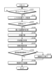
- FIG. 32 is a flow chart showing an example of a main task of processing of the lighting device.
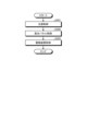
- FIG. 33 is a flow chart illustrating an example of a control task for operation of a lighting device.
- FIG. 34 is a diagram illustrating an example of control before and after changing the irradiation range.
- FIG. 35 is a diagram illustrating an example of control before and after changing the irradiation range.
- FIG. 36 is a diagram illustrating an example of control before and after changing the irradiation range.
- FIG. 37 is a diagram illustrating an example of control before and after changing the irradiation range.
- FIG. 38 is a diagram illustrating an example of control before and after changing the irradiation range.
- FIG. 39 is a diagram illustrating an example of control before and after changing the irradiation range.
- FIG. 40 is a diagram showing an example of control before and after changing the irradiation range.
- FIG. 41 is a diagram showing an example of control before and after changing the irradiation range.
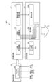
- FIG. 1 is a block diagram showing the functional configuration of the lighting device according to the embodiment of the present disclosure.
- FIG. 2 is a diagram schematically showing the structure of a lighting device according to an embodiment of the present disclosure.
- the lighting device 500 of this example includes a control board 6, a relay board 7, and an output device 8.
- the control board 6 includes a microcomputer 60 .
- the microcomputer 60 inputs position data, brightness data, and room data, and outputs light quantity data, applied voltage data, and rotation angle data, as will be described later.
- the relay board 7 includes a light source relay board 71 , a liquid crystal relay board 72 , and a driving device relay board 73 .
- the relay board 7 relays each data output from the control board 6 and outputs the data to the output device 8 .
- the output device 8 includes a light control section 80, a light distribution section 700, and a drive device 900.
- the output device 8 outputs light LT.
- the light control section 80 has a light source 800 .
- the light distribution unit 700 changes the irradiation shape of the light from the light source 800 based on the input signal.
- the light distribution section 700 has four light distribution panels 1-1 to 1-4.
- the light distribution panels 1-1 to 1-4 transform the light from the light source 800 into an elliptical shape.
- the driving device 900 adjusts the irradiation angle of the light LT.
- the driving device 900 is controlled to irradiate the light LT toward the position of the center point of the ellipse, as will be described later.
- the driving device 900 has a motor for adjusting the irradiation angle of the light LT. In this example, three motors are included as described below.
- the illumination device 500 includes an installation base MB, motors M1 to M3, a substrate K, a light source 800, a reflector 130, and a light distribution section 700.
- the installation base MB is fixed to the ceiling CE of the room.
- the lighting device 500 may be of a type suspended from the ceiling. In that case, the installation base MB is unnecessary.
- the motor M3 is fixed to the installation base MB.
- the motors M1, M2, M3 have rotation axes S1, S2, S3.
- the rotation axes S1, S2, S3 are orthogonal to each other.
- stepper motors can be used as motors M1, M2, M3.
- the motor M1 is a motor for adjusting the angle of the illumination device 500 itself with respect to the surface of the ceiling CE and moving the central position of light irradiation in the X-axis direction.
- the motor M2 is a motor for adjusting the angle of the illumination device 500 itself with respect to the surface of the ceiling CE and moving the central position of light irradiation in the Y-axis direction.
- Motor M3 is a motor for adjusting the rotation angle of lighting device 500 itself with respect to the plane of ceiling CE. By rotating the motors M1 and M2, the center point of the light with respect to the irradiation target can be moved in the X-axis direction and the Y-axis direction. In addition, the rotation of the motor M3 can change the rotation angle of the lighting device 500 itself.
- the board K includes the control board 6 and the relay board 7 described above in this example.
- the board K and each part in the lighting device 500 are electrically connected by a cable (not shown).
- a cable it is preferable to use a flexible cable, for example.
- the light source 800 is, for example, an LED.
- a light-emitting element other than an LED may be used as the light source 800 as long as the amount of light can be controlled.
- the reflector 130 has a curved surface that reflects the light output from the light source 800 .
- Light reflected by the reflector 130 enters the light distribution section 700 .
- the light distribution section 700 emits light from the surface opposite to the surface on which the light is incident. The emitted light is applied to, for example, a table or a floor surface.
- Light distribution unit 700 includes four light distribution panels 1-1 to 1-4.
- the four light distribution panels 1-1 to 1-4 have the same configuration.
- the four light distribution panels 1-1 to 1-4 can change the shape and size of incident light.
- the light distribution panels 1-1 to 1-4 for example, transform the light from the light source 800 into an elliptical shape.
- the light distribution panel 1-1 and the light distribution panel 1-2 are laminated.
- the light distribution panel 1-1 is a light distribution panel for p-wave polarized light.
- the light distribution panel 1-2 is a light distribution panel for s-wave polarized light.
- the light distribution panel 1-1 may be a light distribution panel for s-wave polarization
- the light distribution panel 1-2 may be a light distribution panel for p-wave polarization.
- One of the light distribution panel 1-1 and the light distribution panel 1-2 may be a light distribution panel for p-wave polarization and the other may be a light distribution panel for s-wave polarization.
- the light distribution panel 1-3 and the light distribution panel 1-4 are laminated.
- the light distribution panel 1-3 is a light distribution panel for p-wave polarized light.
- the light distribution panel 1-4 is a light distribution panel for s-wave polarized light.
- the light distribution panel 1-3 may be a light distribution panel for s-wave polarization
- the light distribution panel 1-4 may be a light distribution panel for p-wave polarization.
- One of the light distribution panel 1-3 and the light distribution panel 1-4 may be a light distribution panel for p-wave polarization and the other may be a light distribution panel for s-wave polarization.
- the four light distribution panels 1-1 to 1-4 each have two liquid crystal cells for p-wave polarization and two liquid crystal cells for s-wave polarization. With this configuration, the size and shape of the irradiated light can be changed, and more flexible light distribution control becomes possible.
- FIG. 3 is a block diagram showing the functional configuration of the microcomputer 60.
- the microcomputer 60 includes a position data acquisition section 61, a position data processing section 62, a storage section 63, a D (Digital)/A (Analog) conversion section 64, and a light source drive section 65. , a liquid crystal driving section 66 , a driving device driving section 67 , a light amount setting section 68 , an irradiation shape setting section 69 and an irradiation angle setting section 70 .
- Position data is data indicating the position of each of a plurality of persons (hereinafter sometimes referred to as people) who are detection targets. Position data is obtained, for example, by photographing a plurality of people collectively with an infrared camera and processing the images obtained by the photographing.
- An infrared camera is provided, for example, on the ceiling of a room or on a wall near the ceiling.
- the room data is data related to the room in which the lighting device 500 is installed.
- the room data is data indicating the size of the room in which lighting device 500 is installed.
- the room data is, for example, data indicating the length and width of the floor of the room and the height from the floor to the ceiling.
- the room data is set, for example, when lighting device 500 is installed. Room data may be stored in the storage unit 63 and the room data read out from the storage unit 63 may be used.
- the position data acquisition unit 61 acquires position data indicating the positions of each of a plurality of people around the table provided in the room. For example, the position data acquisition unit 61 receives position data detected by a position sensor (not shown) through wired communication or wireless communication. The position data acquired by the position data acquisition section 61 is input to the position data processing section 62 .
- the position data processing unit 62 calculates ellipse data corresponding to the minimum enclosing ellipse based on the position data acquired by the position data acquisition unit 61 .
- the position data processing unit calculates ellipse data corresponding to the minimum enclosing ellipse surrounding each person's position.
- the position data processing unit obtains an approximate ellipse corresponding to the position of the person, and expands the approximate ellipse to calculate ellipse data corresponding to the minimum enclosing ellipse.
- the position data processing unit 62 approximates each person's position to an ellipse by, for example, the method of least squares, and calculates ellipse data. After that, the ellipse based on the ellipse data is extended to calculate the ellipse data corresponding to the minimum enclosing ellipse.
- the storage unit 63 stores various data.
- the D/A converter 64 receives digital data.
- the D/A converter 64 outputs an analog signal corresponding to digital data.
- the light amount setting unit 68 sets the light amount of the light source 800 based on the ellipse data calculated by the position data processing unit 62 .
- the light amount setting unit 68 sets the light amount based on the area of the ellipse corresponding to the ellipse data, the set brightness, and the data regarding the room in which the lighting device is installed.
- the light amount setting unit 68 generates light amount data corresponding to the set light amount. That is, when setting the light amount, the light amount setting unit 68 generates the light amount data based on the ellipse data (the area of the ellipse), the set brightness, and the data related to the room in which the lighting device is installed. Set the amount of light. In the following description, the same applies to the case where it is described as "based on ellipse data" with respect to the setting of the amount of light.
- the irradiation shape setting unit 69 sets the irradiation shape of the light from the light source 800 based on the elliptical data calculated by the position data processing unit 62 .
- the irradiation shape setting unit 69 sets the light irradiation shape based on the length of the major axis radius and the minor axis radius of the ellipse corresponding to the ellipse data and the data related to the room in which the lighting device is installed.
- Set the irradiation shape of The irradiation shape setting unit 69 generates applied voltage data corresponding to the set light irradiation shape.
- the irradiation shape setting unit 69 when setting the irradiation shape of light, the irradiation shape setting unit 69 generates the applied voltage data based on the ellipse data (major axis radius and minor axis radius) as well as data related to the room in which the lighting device is installed. and set the irradiation shape of the light.
- the irradiation angle setting unit 70 sets the irradiation angle of light from the light source 800 based on the elliptical data calculated by the position data processing unit 62 .
- the irradiation angle setting unit 70 sets the light irradiation angle based on the coordinates of the center point of the ellipse corresponding to the ellipse data, the inclination of the ellipse, and the data related to the room in which the lighting device is installed. to set the irradiation angle of the
- the irradiation angle setting unit 70 generates rotation angle data corresponding to the set irradiation angle of light.
- the irradiation angle setting unit 70 sets the rotation angle based on the ellipse data (the coordinates of the center point of the ellipse, the inclination of the ellipse) and the data related to the room in which the lighting device is installed. Generate data and set the irradiation angle of light. In the following description, the same applies to the case where it is described as "based on ellipse data" with respect to the setting of the irradiation angle of light.
- the light source driving section 65 outputs light amount data for driving the light source 800 in the light adjusting section 80 based on the light amount data generated by the light amount setting section 68 .
- the liquid crystal driving section 66 outputs applied voltage data to be applied to the light distribution panels 1-1 to 1-4 in the light distribution section 700 based on the applied voltage data generated by the irradiation shape setting section 69.
- the driving device driving section 67 outputs rotation angle data for driving each motor of the driving device 900 based on the rotation angle data generated by the irradiation angle setting section 70 .
- the illumination device 500 described with reference to FIGS. emit a light based on People in the room are irradiated with the light emitted by the lighting device 500 . According to the illumination device 500, operation is not troublesome, energy is not wasted, and energy saving can be achieved.
- FIG. 4 is a diagram illustrating an example of a light irradiation range by a lighting device of a comparative example.
- FIGS. 5 to 14 are diagrams showing examples of the light irradiation range of the lighting device of the present disclosure.
- FIGS. 4 to 14 it is assumed that a horizontally long table with a non-square shape when viewed from the ceiling side is installed in the room. In such a case, if a circular light is emitted, the light may be emitted even in a place where no person is present, resulting in a wastefully irradiated portion. That is, in addition to the area where people are present, the area where no people are present is also irradiated with light, resulting in wasted power consumption and energy saving.
- the light is irradiated to the portions where no people are present, and part of the light is irradiated to the walls other than the floor FL. or Therefore, the light is irradiated to a portion that should not be irradiated originally, and energy is wasted.
- the light irradiation area in the case of FIG. 5 is 50% of the light irradiation area in the case of FIG. Therefore, as shown in FIG. 5, the energy can be effectively utilized without waste by minimizing the irradiation area within the necessary range. It is assumed that the power consumption is proportional to the light irradiation area. The same applies to the following description.
- FIG. 6 shows a state in which two persons P1 and P3 are seated at the end of the table TL. In the case of FIG. 6, two persons P1 and P3 are seated facing each other.
- FIG. 6 shows a state in which light is applied to a portion where a person is present, and light is not applied to an unnecessary portion. That is, in FIG. 6, light of an ellipse D2 having a smaller area than the ellipse D1 shown in FIG. 5 is irradiated. At this time, the ellipse D2 is vertically long unlike the ellipse D1. Therefore, for example, the light irradiation area in the case of FIG. 6 is 20% of the light irradiation area in the case of FIG. Therefore, as shown in FIG. 6, energy can be effectively utilized without waste by reducing the irradiation area as much as possible within the necessary range.
- FIG. 7 shows a state where four persons P6, P7, P8 and P9 are seated near the center of the table TL.
- light of a perfect circle or an ellipse D3 close to a perfect circle is irradiated.
- FIG. 7 shows a state in which light is irradiated to a portion where a person is present, and light is not irradiated to an unnecessary portion. That is, in FIG. 7, light of an ellipse D3 having an area smaller than that of the ellipse D0 shown in FIG. 4 is irradiated. Therefore, for example, the light irradiation area in the case of FIG. 7 is 30% of the light irradiation area in the case of FIG. Therefore, as shown in FIG. 7, the energy can be effectively used without waste by reducing the irradiation area as much as possible within the necessary range.
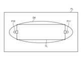
- FIG. 8 shows a state in which a person P10 is seated at one end of the table TL and a person P11 is seated at the other end.
- light of oblong ellipse D4 is irradiated.
- FIG. 8 shows a state in which light is applied to a portion where a person is present, and light is not applied to an unnecessary portion. That is, in FIG. 8, light of an ellipse D4 having an area smaller than that of the ellipse D0 shown in FIG. 4 is irradiated. Therefore, for example, the light irradiation area in the case of FIG. 8 is 50% of the light irradiation area in the case of FIG. Therefore, as shown in FIG. 8, the energy can be effectively used without waste by reducing the irradiation area as much as possible within the necessary range.
- the light irradiation area in the case of FIG. 10 is 40% of the light irradiation area in the case of FIG. Therefore, as shown in FIG. 10, energy can be effectively used without waste by reducing the irradiation area as much as possible.
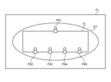
- FIG. 11 shows a state in which a person P41 is seated near the center of one of the long sides of the table TL, and persons P42, P43, P44 and P45 are seated on the other long side of the table TL.
- the entire table TL is irradiated with the horizontally long elliptical light D7.
- FIG. 11 shows a state in which light is applied to a portion where a person is present, and light is not applied to an unnecessary portion. That is, in FIG. 11, light of an ellipse D7 having an area smaller than that of the ellipse D0 shown in FIG. 4 is irradiated. Therefore, for example, the light irradiation area in the case of FIG. 11 is 60% of the light irradiation area in the case of FIG. Therefore, as shown in FIG. 11, the energy can be effectively used without waste by minimizing the irradiation area within the necessary range.
- FIG. 12 shows a state in which persons P51, P52, P53 and P54 are seated on one long side of the table TL, and persons P55, P56, P57 and P58 are seated on the other long side.
- the entire table TL is irradiated with the horizontally long elliptical light D8.
- FIG. 12 shows a state in which light is applied to a portion where a person is present, and light is not applied to an unnecessary portion. That is, in FIG. 12, light of an ellipse D8 having an area smaller than that of the ellipse D0 shown in FIG. 4 is irradiated. Therefore, for example, the light irradiation area in the case of FIG. 12 is 70% of the light irradiation area in the case of FIG. Therefore, as shown in FIG. 12, energy can be effectively utilized without waste by reducing the irradiation area as much as possible within the necessary range.
- FIGs. 13 and 14 are diagrams for explaining a case in which a person leaves the seat in the middle. 13 shows the state before leaving the seat, and FIG. 14 shows the state after leaving the seat.
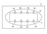
- FIG. 13 shows a state in which persons P61, P62, P63 and P64 are seated on one of the long sides of the table TL, and persons P65, P66, P67 and P68 are seated on the other long side of the table TL.
- the entire table TL is irradiated with light of a horizontally long ellipse D9.
- light of an ellipse D9 having an area smaller than that of the ellipse D0 shown in FIG. 4 is irradiated. Therefore, for example, the light irradiation area in the case of FIG. 13 is 70% of the light irradiation area in the case of FIG.
- FIG. 14 shows a state in which persons P62, P63 and P64 on one of the long sides of the table TL have left their seats and persons P67 and P68 on the other long side of the table TL have left their seats from the state of FIG. Therefore, in the case of FIG. 14, the people P61, P65 and P66 who are currently seated are irradiated with light of an ellipse D10 smaller than the ellipse D9 of FIG. In the case of FIG. 14, light of an ellipse D10 having an area smaller than that of the ellipse D0 shown in FIG. 4 is irradiated. Therefore, for example, the light irradiation area in the case of FIG. 14 is 30% of the light irradiation area in the case of FIG. As described above, energy can be effectively utilized without waste by reducing the irradiation area as much as possible within a necessary range.
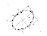
- FIG. 15 is a diagram illustrating an example of processing by the position data processing unit 62. As shown in FIG. The position data processing unit 62 performs ellipse approximation to obtain the data of the ellipse DA, and then enlarges the ellipse DA to calculate the data of the minimum enclosing ellipse DA'.
- Each rhombus in FIG. 15 indicates the position of the person acquired by the position data acquisition unit 61 .
- the position of each rhombus can be approximated to the ellipse DA by, for example, the method of least squares.
- length a be the radius of the major axis of ellipse DA
- length b be the radius of the minor axis of ellipse DA
- angle ⁇ be the angle between the major axis of ellipse DA and the X axis, that is, the inclination angle of ellipse DA.
- the ellipse DA can be expressed by equation (1).
- equation (3) By transposing "1" on the right side of equation (1) to the left side and replacing the unknown part with variables A 0 , B 0 , C 0 , D 0 , E 0 , and F 0 , equation (3) is obtained.
- equation (3) the variable can be reduced by one by dividing the entire equation by any of the variables A 0 , B 0 , C 0 , D 0 , E 0 , and F 0 , and equation (4) can be put as
- Equation (5) is partially differentiated by A, B, C, D, and E and represented by a matrix, resulting in Equation (6).
- Equation (10a) the coordinates (X 0 , Y 0 ) of the center of the ellipse DA to be obtained are given by the equations (8a) and (8b).
- the angle ⁇ is given by equation (9).
- the length a of the major axis radius of the ellipse is expressed by Equation (10a)
- the length b of the minor axis radius of the ellipse is expressed by Equation (10b).
- the ellipse DA is enlarged so that the ellipses before and after the enlargement have similar shapes.
- the ellipse DA is enlarged so that the rhombus P farthest from the center point of the ellipse passes through the outer circumference of the minimum enclosing ellipse DA'.
- an ellipse slightly larger than the minimum enclosing ellipse DA' may be used. For example, in FIG. 15, an ellipse that completely contains the rhombus P may be obtained.
- the ellipse DA passing through the rhombus P may be, for example, an ellipse with the major axis radius a increased by 5% and the minor axis radius b increased by 5%.
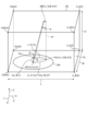
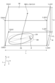
- FIG. 16 is a diagram illustrating an installation example of a lighting device.
- FIG. 16 shows a room in which lighting device 500 is installed.
- the room in which the lighting device 500 is installed has a length of L, a width of W, and a height of H.
- the direction along the length L is the X-axis direction
- the direction along the width W is the Y-axis direction
- the direction along the height H is the Z-axis direction.
- a lighting device 500 is provided on the ceiling CE of the room. Below the illumination device 500 are five persons P1 to P5. Ellipse DA is the minimum enclosing ellipse that encloses persons P1 to P5.
- the position data processing unit 62 described above calculates ellipse data corresponding to the ellipse DA based on the position data of the persons P1 to P5.
- a center point P0 in FIG. 16 is the center point of the ellipse DA.
- a perpendicular line sh in FIG. 16 is a perpendicular line extending from the lighting device 500 toward the floor FL.
- Illumination device 500 controls motors M1 and M2 of driving device 900 so as to irradiate light toward the position of center point P0 of ellipse DA.
- light may be applied to a range slightly wider than the range of the minimum enclosing ellipse. It is preferable to adjust how wide the range should be at the site of the room in which the lighting device 500 is installed. In order to irradiate a slightly wider range, it is realized by slightly increasing the degree of diffusion of the light by the light distribution panels 1-1 to 1-4. For example, an elliptical range lengthened by about 5% with respect to the major axis radius a and the minor axis radius b may be irradiated.
- the area s of the ellipse DA can be calculated by multiplying the product of the major axis radius a and the minor axis radius b of the ellipse DA by the circular constant ⁇ .
- the amount of light Lm can be set based on the area s, height H and brightness BL of the ellipse DA. The larger the area of the ellipse DA, the larger the light amount data Lm. As the height H of the room increases, the light amount data of the light amount Lm increases. The higher the requested brightness is, the larger the light amount data Lm is.
- FIG. 17 is a diagram for explaining rotation angles of motors M1 and M2 of drive device 900.
- the coordinates of the four corners of the floor FL are (0,0,0), (L,0,0), (0,W,0), and (L,W,0).
- the coordinates of the four corners of the ceiling CE are (0, 0, H), (L, 0, H), (0, W, H), and (L, W, H).
- the coordinates of the central position of lighting device 500 are (L/2, W/2, H).
- the coordinates of the leg Psh of the perpendicular sh are (L/2, W/2, 0).
- the coordinates of the center point P0 of the ellipse DA are (Cx, Cy, 0).
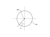
- the rotation angle of the motor M1 is assumed to be an angle ⁇
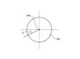
- the rotation angle of the motor M2 is assumed to be an angle ⁇ .
- Pm be the center position of the light irradiation after being moved by the rotation of the motor M1.
- the distance between the center point P0 and the point Pm is L/2-Cx
- the distance between the point Pm and the foot Psh of the perpendicular sh The distance is Cy-W/2. Therefore, the distance between the center point P0 and the foot Psh of the perpendicular sh is (L/2-Cx) 2 +(Cy-W/2) 2 .
- FIG. 18 is a diagram explaining the rotation angle of the motor M1 of the driving device 900.
- the rotation of the motor M1 moves the center position of the light irradiation in the X-axis direction.
- the rotation angle of the motor M1 with respect to the illumination device 500 is an angle ⁇ .
- FIG. 19 is a diagram explaining the rotation angle of the motor M2 of the driving device 900.
- the rotation of the motor M2 moves the center position of the light irradiation in the Y-axis direction.
- the rotation angle of the motor M2 with respect to the illumination device 500 is an angle ⁇ .
- FIG. 21 Next, the light distribution panel 1 included in the light distribution section 700 will be described with reference to FIGS. 21 to 25.
- FIG. 21 and subsequent figures a coordinate system different from the XYZ coordinate system shown in FIGS. 15 to 20 is used.
- FIG. 21 is a perspective view of the light distribution panel according to the embodiment.
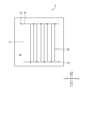
- FIG. 22 is a plan view showing the wiring of the array substrate of the light distribution panel according to the embodiment, and is a view of the array substrate viewed from above.
- FIG. 23 is a plan view showing the wiring of the opposing substrate of the light distribution panel according to the embodiment, and is a view of the opposing substrate viewed from above.
- FIG. 24 is a plan view showing wiring of the light distribution panel according to the embodiment, and is a view of the light distribution panel as seen from above. 25 is a cross-sectional view taken along line IV-IV of FIG. 24.
- the light distribution panel 1 has an array substrate 2, a counter substrate 3, a liquid crystal layer 4, and a sealing material 30.
- the array substrate (first substrate) 2 is larger than the opposing substrate (second substrate) 3. That is, the area of the counter substrate (second substrate) 3 is smaller than the area of the array substrate (first substrate) 2 .
- the array substrate 2 has transparent glass 23 (see FIG. 22).
- the counter substrate 3 has a transparent glass 31 (see FIG. 23).
- the array substrate 2 and the counter substrate 3 are square when viewed from above, but the shape of the substrate according to the present invention is not limited to square.
- a first terminal group area 21 and a second terminal group area 22 are provided on the surface 2 a of the array substrate 2 .
- the first terminal group area 21 is located at the end on the y1 side of the surface 2a of the array substrate 2 .
- the second terminal group area 22 is located at the end of the surface 2a of the array substrate 2 on the x2 side.
- the first terminal group area 21 and the second terminal group area 22 have an L shape when viewed from above.
- the first terminal group 10 is arranged in the first terminal group area 21
- the second terminal group 20 is arranged in the second terminal group area 22 . Since the area of the counter substrate 3 is smaller than that of the array substrate 2, the first terminal group 10 and the second terminal group 20 are exposed. Further, the first terminal group 10 and the second terminal group 20 are also simply referred to as terminal portions.
- the first terminal group 10 includes a first terminal 101, a second terminal 102, a third terminal 103, a fourth terminal 104, a first pad 105, and a second terminal.
- Pad 106 , third pad 107 , fourth pad 108 , fifth pad 109 , sixth pad 110 , seventh pad 111 and eighth pad 112 are included.
- the seventh pad 111 and the eighth pad 112 are arranged side by side in order from the x1 side to the x2 side in the horizontal direction.
- the first pad 105 and the eighth pad 112 are electrically connected via the lead wire 113 .
- the second pad 106 and the seventh pad 111 are electrically connected via the lead wire 113 .
- the third pad 107 and the sixth pad 110 are electrically connected via the lead wire 113 .
- the fourth pad 108 and the fifth pad 109 are electrically connected via the lead wire 113 .
- the second terminal group 20 includes a fifth terminal 201, a sixth terminal 202, a seventh terminal 203, an eighth terminal 204, a ninth pad 205, and a tenth terminal. It includes a pad 206 , an eleventh pad 207 , a twelfth pad 208 , a thirteenth pad 209 , a fourteenth pad 210 , a fifteenth pad 211 and a sixteenth pad 212 .
- the fifteenth pad 211 and the sixteenth pad 212 are arranged side by side in order in the front-rear direction from the y2 side to the y1 side.
- the ninth pad 205 and the sixteenth pad 212 are electrically connected via a lead wire 213 .
- the tenth pad 206 and fifteenth pad 211 are electrically connected via a lead wire 213 .
- the eleventh pad 207 and the fourteenth pad 210 are electrically connected via a lead wire 213 .
- the twelfth pad 208 and the thirteenth pad 209 are electrically connected via a lead wire 213 .
- the counter substrate 3 is arranged above the array substrate 2 (on the z1 side).
- a sealing material 30 and a liquid crystal layer 4 are provided between the opposing substrate 3 and the array substrate 2 .
- the sealing material 30 is annularly provided along the outer periphery of the opposing substrate 3 , and the inside of the sealing material 30 is filled with the liquid crystal layer 4 .
- the area where the liquid crystal layer 4 is provided is the active area, the outside of the liquid crystal layer 4 is the frame area, and the first terminal group area 21 and the second terminal group area 22 are terminal areas.
- the wiring of the array substrate 2 and the counter substrate 3 will be described.
- the wiring is provided on the front surface of the substrate and the rear surface thereof. That is, the surface on which the wiring is provided is defined as the front surface, and the surface opposite to the front surface is defined as the back surface.
- wiring is provided on the upper surface 2a of the front surface 2a and the rear surface 2b of the array substrate 2, and wiring is provided on the lower surface 3a of the front surface 3a and the rear surface 3b of the counter substrate 3. is provided.
- the surface 2a of the array substrate 2 and the surface 3a of the counter substrate 3 are arranged to face each other with the liquid crystal layer 4 interposed therebetween.
- the wiring 32 and the second electrode 33 are provided on the surface 3a of the opposing substrate 3. As shown in FIG. Specifically, wirings 32 are provided on the y1 side and the y2 side, respectively. The wiring 32 extends in the x direction. A second electrode 33 is electrically connected to the wiring 32 . The second electrodes 33 extend in the y direction. The wiring 32 is provided with connection portions C3 and C4. Although the number of the first electrodes 25 and the number of the second electrodes 33 are eight in the examples shown in FIGS. It does not indicate the number of two electrodes 33 . The number of the first electrodes 25 and the number of the second electrodes 33 may be two or more, and naturally may be nine or more.
- the opposing substrate 3 is arranged above the array substrate 2 with a space therebetween.
- a liquid crystal layer 4 is filled between the array substrate 2 and the counter substrate 3 .
- the connection portion C1 of the array substrate 2 and the connection portion C3 of the counter substrate 3 are electrically connected via a conductive column (not shown).
- the connection portion C2 of the array substrate 2 and the connection portion C4 of the counter substrate 3 are electrically connected via a conductive column (not shown).
- the first terminal 101, the second terminal 102, the third terminal 103, the fourth terminal 104, the first pad 105, the second pad 106, the third pad 107, and the fourth pad 108 are , can be electrically connected to an FPC (Flexible Printed Circuits) 40 indicated by a two-dot chain line.
- the plurality of light distribution panels 1-1 to 1-4 are connected to the D/A converter 64 via, for example, FPCs 40 individually provided.
- FIG. 26 is a schematic diagram showing the configuration of the light distribution section 700.
- the light distribution section 700 has, for example, four light distribution panels 1-1 to 1-4 stacked in the z direction.
- the four light distribution panels 1-1 to 1-4 are the light distribution panels 1-1 to 1-4 described with reference to FIGS. 21 to 25.
- FIG. The four light distribution panels 1-1 to 1-4 are stacked such that the respective liquid crystal layers 4 are overlapped, and the arrangement of the plurality of first electrodes 25 and the plurality of second electrodes 33 of each panel are overlapped in a plan view.
- a planar viewpoint is a viewpoint that views a plane along the x-direction and the y-direction from the front.
- a region in which the plurality of first electrodes 25 and the plurality of second electrodes 33 are arranged functions as a light distribution control region LDA shown in FIG. 27 and the like, which will be described later.
- FIG. 27 is a schematic diagram showing an example of light distribution control by the light distribution control area LDA.
- the light distribution control area LDA is an area in which the plurality of first electrodes 25 and the plurality of second electrodes 33 are arranged in plan view. That is, the light distribution control area LDA includes a plurality of electrodes extending in the x direction and arranged in the y direction, and a plurality of electrodes extending in the y direction and arranged in the x direction.
- the electrodes extending in the x direction and arranged in the y direction are, for example, the first electrodes 25 .
- the electrodes extending in the y direction and arranged in the x direction are, for example, the second electrodes 33 .
- the light distribution unit 700 has four light distribution panels 1-1 to 1-4 overlapping in the z direction, a plurality of electrodes extending in the x direction and arranged in the y direction and a plurality of electrodes extending in the y direction and arranged in the x direction are provided. A plurality of electrodes arranged side by side is quadruple in the z direction.
- a plurality of electrodes extending in the x direction and lined up in the y direction and a plurality of electrodes extending in the y direction and lined up in the x direction of the four light distribution panels 1-1 to 1-4 of the light distribution unit 700 By controlling the potential of each of the light distribution control areas LDA, the light distribution control area LDA can be controlled from one surface side of the light distribution section 700, for example, as in the examples E1, E2, E3, and E4 of the "example of light distribution pattern" shown in FIG. It is possible to control the transmission range and the degree of transmission of light directed toward the other side.
- Example E1 in FIG. 27 shows the light source when all the potentials of the plurality of electrodes extending in the x direction and aligned in the y direction and the plurality of electrodes extending in the y direction and aligned in the x direction are 0 volts (V).
- FIG. 4 is a schematic diagram showing a state in which the light distribution control area LDA is viewed from the opposite side of (for example, the light source 800) from a planar viewpoint. In example E1, the light from the light source is transmitted through the light distribution control area LDA almost as it is.
- FIG. 10 is a schematic diagram showing a state in which the light distribution control area LDA is seen from the opposite side of the light source (for example, the light source 800) from a planar viewpoint when the potential exceeds the potential.
- the light distribution control area LDA in the state of controlling .
- the potential of a plurality of electrodes extending in the x direction and arranged in the y direction exceeds 0 volt (V), and the potential of the plurality of electrodes extending in the y direction and arranged in the x direction is 0 volt ( V)
- the light distribution control area LDA is viewed from the opposite side of the light source (for example, the light source 800) from a plan view.
- the light from the light source spreads relatively greatly in the y direction, but does not spread so much in the x direction. , shows the light distribution control area LDA in the state of controlling .
- Example E4 is a light source when all the potentials of the plurality of electrodes extending in the x-direction and aligned in the y-direction and the plurality of electrodes extending in the y-direction and aligned in the x-direction are potentials exceeding 0 volts (V).
- FIG. 4 is a schematic diagram showing a state in which the light distribution control area LDA is viewed from the opposite side of (for example, the light source 800) from a planar viewpoint.
- the light from the light source is largely blocked by the light distribution control area LDA, so that when viewed from the opposite side of the light source across the light distribution control area LDA, the overall state is dark.
- a light distribution control area LDA is shown.
- the light distribution control area LDA has two or more electrodes extending in the x direction and aligned in the y direction and two or more electrodes extending in the y direction and aligned in the x direction from a plan view. It is good if there is Here, one light distribution control area LDA has m electrodes extending in the x direction and arranged in the y direction, and n electrodes extending in the y direction and arranged in the x direction. This is the first condition. In one light distribution panel 1-1 to 1-4, the number of electrodes (for example, first electrodes 25) extending in the x direction and arranged in the y direction is m ⁇ p.
- a second condition is that the number of electrodes (for example, the second electrodes 33) arranged in the x direction is n ⁇ q.
- the light distribution section 700 can set p light distribution control areas LDA in the x direction and q light distribution control areas LDA in the y direction in a matrix.
- m, n, p, and q are natural numbers of 2 or more.
- the entire active area (the area in which the liquid crystal layer 4 is provided) of one light distribution panel in plan view may be one light distribution control area LDA.
- examples E1, E2, E3, and E4 shown in FIG. 27 particularly show the difference in the shape of the light distribution range from the plane viewpoint due to the potential control.
- the relationship between the potential applied to the first electrode 25 and the potential applied to the second electrode 33 determines the shape of the light transmission range and the size of the light transmission range. can be controlled more flexibly. With this control, the shape and size of the emitted light can be changed.
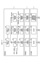
- FIG. 28 is a diagram showing an example of data flow in lighting device 500.
- FIG. 28 shows the flow of data in the control board 6, the relay board 7 and the output device 8 that constitute the illumination device 500.
- the position data acquisition unit 61 of the control board 6 acquires position data.
- the position data processing unit 62 calculates ellipse data corresponding to the positions of a plurality of people based on the position data acquired by the position data acquisition unit 61 .
- the ellipse data calculated by the position data processing unit 62 is input to the light amount setting unit 68 , the irradiation shape setting unit 69 and the irradiation angle setting unit 70 .
- the light amount setting section 68 sets the light amount of the light source based on the ellipse data calculated by the position data processing section 62 . At this time, the light amount setting unit 68 sets the light amount based on the area of the ellipse corresponding to the ellipse data, the set brightness, and the data regarding the room in which the lighting device is installed. The light amount setting unit 68 generates light amount data corresponding to the set light amount.
- the light source driving section 65 outputs a voltage for causing the light source 800 in the light control section 80 to emit light based on the light amount data generated by the light amount setting section 68 .
- the light source relay board 71 relays the voltage output by the light source driving section 65 .
- a voltage output from the light source drive unit 65 is input to the light control unit 80 .
- Light is output by operating the light source 800 in the light control unit 80 .
- the irradiation shape setting unit 69 sets the irradiation shape of the light from the light source based on the elliptical data calculated by the position data processing unit 62 . At this time, the irradiation shape setting unit 69 sets the irradiation shape of the light based on the length of the major axis radius and the minor axis radius of the ellipse corresponding to the ellipse data and the data regarding the room in which the lighting device is installed. . The irradiation shape setting unit 69 generates applied voltage data corresponding to the set light irradiation shape.
- the applied voltage data generated by the irradiation shape setting unit 69 is data indicating applied voltages corresponding to the X-axis direction and the Y-axis direction of the ellipse.
- the liquid crystal driving section 66 outputs voltages to be applied to the light distribution panels 1-1 to 1-4 in the light distribution section 700 based on the applied voltage data generated by the irradiation shape setting section 69.
- FIG. The liquid crystal relay board 72 relays the voltage output by the liquid crystal driving section 66 .
- a voltage output from the liquid crystal drive unit 66 is input to the light distribution unit 700 .
- Light can be diffused by the operation of the light distribution panels 1-1 to 1-4 in the light distribution section 700.
- the irradiation angle setting unit 70 sets the irradiation angle of the light from the light source based on the elliptical data calculated by the position data processing unit 62 . At this time, the irradiation angle setting unit 70 sets the irradiation angle of the light based on the coordinates of the center point of the ellipse corresponding to the ellipse data, the inclination of the ellipse, and the data regarding the room in which the lighting device is installed. . The irradiation angle setting unit 70 generates rotation angle data corresponding to the set irradiation angle of light.
- the driving device driving section 67 outputs a voltage for rotating each motor in the driving device 900 based on the rotation angle data generated by the irradiation angle setting section 70 . That is, the driving device driving section 67 outputs a control voltage for the X-axis direction motor, a control voltage for the Y-axis direction motor, and a control voltage for the elliptical tilt motor.
- the driving device relay board 73 relays the voltage output by the driving device driving section 67 .
- Each voltage output by the driving device driving section 67 is input to the driving device 900 .
- the light irradiation direction can be changed by the operation of each motor in the driving device 900 .
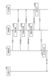
- FIGS. 29 to 31 are sequence diagrams showing examples of the timing of data transmission/reception of each unit in lighting device 500.
- FIG. 29 to 31 are sequence diagrams showing examples of the timing of data transmission/reception of each unit in lighting device 500.
- FIG. 29 shows an example of the timing of transmission and reception of each data when the lighting device 500 starts operating.
- the control board 6 sends the initial value of the light amount data to the relay board 7 .
- the relay board 7 relays the initial value of the light amount data (step S701) and sends the initial value of the light amount data to the output device 8.
- control board 6 sends the initial value of the applied voltage to the relay board 7 .
- the relay board 7 relays the initial value of the applied voltage data (step S702) and sends the initial value of the applied voltage data to the output device 8.
- control board 6 sends the initial value of the rotation angle data to the relay board 7 .
- the relay board 7 relays the initial value of the rotation angle data (step S703) and sends the initial value of the rotation angle data to the output device 8.
- the output device 8 outputs a response signal (step S704), and the response signal is sent to the control board 6 via the relay board 7. Then, the control board 6 outputs a start instruction (step S705), and this start instruction is sent to the position sensor 600.
- FIG. This causes the position sensor 600 to start detecting the positions of people.
- FIG. 30 shows an example of the timing of transmission and reception of each data while the lighting device 500 is in operation.
- step S600 when the position sensor 600 detects the positions of people (step S600), position data regarding the positions of the people is sent from the position sensor 600 to the control board 6.
- the control board 6 acquires the position data (step S601), it calculates ellipse data corresponding to the minimum enclosing ellipse based on the position data (step S602). After that, the control board 6 calculates light amount data based on the ellipse data (step S603).
- the control board 6 calculates applied voltage data based on the ellipse data (step S604).
- the control board 6 calculates rotation angle data based on the ellipse data (step S605).
- control board 6 When the control board 6 outputs the light intensity data, it is relayed by the relay board 7 (step S701a) and sent to the output device 8.
- the output device 8 sets the light intensity of the light source 800 based on the light intensity data.
- control board 6 When the control board 6 outputs the applied voltage data, it is relayed by the relay board 7 (step S702a) and sent to the output device 8.
- the output device 8 sets the degree of diffusion by each of the light distribution panels 1-1 to 1-4 of the light distribution section 700 based on the applied voltage data.
- control board 6 When the control board 6 outputs the rotation angle data, it is relayed by the relay board 7 (step S703a) and sent to the output device 8.
- the output device 8 rotates each motor of the driving device 900 based on the rotation angle data.
- the output device 8 outputs a response signal (step S704a), and the response signal is sent to the control board 6 via the relay board 7. Thereafter, operations similar to those described above are repeatedly performed at predetermined intervals during the operation of the illumination device 500 .
- By performing the operation at a predetermined cycle it is possible to cope with the increase or decrease in the number of people in the room. That is, as described with reference to FIGS. 13 and 14, when the number of people in the room increases or decreases, the positions of the plurality of people indicated by the position data change.
- the position data processing unit 62 calculates elliptical data based on the changed position data
- the light amount setting unit 68 sets the light amount of the light source based on the elliptical data based on the changed position data, and sets the irradiation shape.
- a unit 69 sets the irradiation shape of the light based on the ellipse data based on the position data after the change
- an irradiation angle setting unit 70 sets the center point of the ellipse based on the position data after the change to the center of the ellipse based on the position data before the change.
- the driving device 900 is controlled to adjust the irradiation angle so as to match the points.
- FIG. 31 shows an example of the timing of transmission and reception of each data at the end of the operation of the lighting device 500.
- the control board 6 sends the light amount data to the relay board 7 as "0".
- the relay board 7 relays this light quantity data (step S701b) and sends it to the output device 8.
- control board 6 sends the applied voltage to the relay board 7 as "0".
- the relay board 7 relays this applied voltage data (step S702b) and sends it to the output device 8.
- control board 6 sends the rotation angle data to the relay board 7 as "0".
- the relay board 7 relays the rotation angle data (step S703b) and sends it to the output device 8.
- the output device 8 outputs a response signal (step S704b), and the response signal is sent to the control board 6 via the relay board 7. Then, the control board 6 outputs an end instruction (step S706), and this end instruction is sent to the position sensor 600.
- FIG. Accordingly, the position sensor 600 ends the operation of detecting the positions of people.
- FIG. 32 and 33 are flowcharts showing an operation example of lighting device 500.
- FIG. FIG. 32 is a flow chart showing an example of the main task of the processing of lighting device 500 .
- the processing waits until a timeout of a timer (not shown) is detected (No in step S101). When the timeout of the timer is detected, the process proceeds to the next process (Yes in step S101). The subsequent processes are repeated at a predetermined cycle by a timer (not shown).
- the lighting device 500 acquires people's position data (step S102).
- the illumination device 500 determines whether or not the acquired position data is different from the previously acquired position data (step S103).
- step S104 ellipse data corresponding to the minimum enclosing ellipse is calculated (step S104).
- step S105 the amount of light is calculated based on the ellipse data.
- step S106 the applied voltages to be applied to the light distribution panels 1-1 to 1-4 are calculated (step S106).
- step S107 the rotation angle is calculated based on the ellipse data (step S107).
- step S108 it is determined whether or not the adjustment of the lighting device has been completed. If it is determined in step S108 that the adjustment of the lighting device has ended (Yes in step S108), the control task, which is the next process, is activated (step S109). As a result, the process shifts to the control task described with reference to FIG. 33 .
- step S103 If it is determined in step S103 that there is no change in the content of the position data (No in step S103), the process returns to step S101 to continue processing. If it is determined in step S108 that the adjustment of the lighting device has not been completed (No in step S108), the control task is terminated (step S110), and the control task is activated (step S109). As a result, the process shifts to the control task described with reference to FIG. 33 . In step S103, when the position data is acquired for the first time, it can be considered that there is a change. It should be noted that the order of operations shown in FIG. 32 is an example, and the order of operations of each unit of lighting device 500 may be changed.
- FIG. 33 is a flowchart showing an example of control tasks for the operation of the lighting device 500.
- FIG. FIG. 33 shows an example of the order of control of each unit of lighting device 500 .
- the control of the light source 800 of the dimming unit 80 is performed (step S201).
- the light distribution panels 1-1 to 1-4 of the light distribution unit 700 are controlled (step S202).
- the driving device 900 is controlled (step S203). Note that the order of control shown in FIG. 33 is an example, and the order of control of each unit of lighting device 500 may be changed.
- control of the light source 800, control of the light distribution panels 1-1 to 1-4, and control of the driving device 900 are performed in this order. If the irradiation range of light changes, there is a possibility that people in the room will feel uncomfortable. Therefore, it is preferable to control the amount of light so as not to cause discomfort.
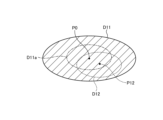
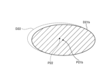
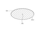
- 34 to 41 are diagrams showing an example of control before and after changing the irradiation range. 34 to 41 are diagrams for explaining control that does not give a sense of discomfort while changing the irradiation range of light. In FIGS. 34 to 37, the light amount is indicated by hatching intervals. Closely spaced hatching indicates high light (ie, bright), and widely spaced hatching indicates low light (ie, dark).
- the amount of light is adjusted as follows. First, the ellipse D11 is moved by the operation of the driving device 900 . In this example, the position of the ellipse D11 shown in FIG. 34 is moved to the position of the ellipse D11' shown in FIG.
- the driving device 900 moves so that the center point P0 of the ellipse D11 shown in FIG. 34 and the center point P12 of the ellipse D12 after the movement coincide with each other.
- the ellipse D11a and the ellipse D11 have the same center point and are similar shapes.
- the ellipse D11a' and the ellipse D11' have the same center point and similar shapes.
- the ellipse D11a' and the ellipse D12 are the same ellipse, but are shown slightly shifted for convenience of drawing.
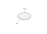
- the area of the ellipse D11' shown in FIG. 35 is reduced by the operation of the light distribution unit 700 to form the ellipse D11b shown in FIG.
- the ellipse D11b and the ellipse D12 are the same ellipse, but they are shown slightly shifted for convenience of drawing.
- the ellipse D11b becomes brighter than the ellipse D11' because the area is reduced.
- an ellipse D11b' shown in FIG. 37 is formed.
- the ellipse D11b' has the same brightness as the ellipse D11'.
- the ellipse D11b' and the ellipse D12 are the same ellipse, but are shown slightly shifted for convenience of drawing.
- the driving device 900, the light distribution unit 700, and the light source 800 are controlled in this order.
- the light amount of the light source 800 is reduced.
- the driving device 900 aligns the center point P12 of the ellipse D12, which is the light irradiation range after the change shown in FIG. 34, with the center point P0 of the ellipse D11, which is the light irradiation range before the change. move. That is, the center points before and after the change are matched.
- the ellipse D11 which is the light irradiation range before change
- the ellipse D12 which is the light irradiation range after change, shown in FIG. 34 have similar shapes with the same central point P0.
- the ellipse D21 and the ellipse D21b have the same center point and are similar shapes.
- the ellipse D21a and the ellipse D21b have the same center point and are similar shapes.
- the area of the ellipse D21a shown in FIG. 39 is enlarged to form the ellipse D21b shown in FIG.
- the center point P21a of the ellipse D21a shown in FIG. 39 and the center point P21b of the ellipse D21b shown in FIG. 40 are at the same position. Therefore, the ellipse D21a and the ellipse D21b have the same center point and are similar in shape.
- the ellipse D21b is darker than the ellipse D21a because the area is expanded, although the light intensity is not controlled. 40 is moved to the position of the ellipse D22 shown in FIG.
- the center point P21b of the ellipse D21b is moved so as to coincide with the center point P22 of the ellipse D22.
- the ellipse D21b' and the ellipse D22 are the same ellipse, but are shown slightly shifted for convenience of drawing.
- the light source 800, the light distribution unit 700, and the driving device 900 are controlled in this order.
- the light distribution unit 700 and the driving device 900 are controlled in this order.
- the center point P22 of the ellipse D22, which is the light irradiation range after the change shown in FIG. 41, and the center point P21b of the ellipse D21b, which is the light irradiation range before the change shown in FIG. Move to match. That is, the center points before and after the change are matched.
- a light source a position data acquisition unit that acquires position data indicating the positions of each of the plurality of detection targets; a position data processing unit that calculates ellipse data corresponding to the positions of the plurality of detection targets based on the position data; a light amount setting unit that sets the light amount of the light source based on the ellipse data calculated by the position data processing unit; an irradiation shape setting unit that sets an irradiation shape of light from the light source based on the elliptical data calculated by the position data processing unit; an irradiation angle setting unit that sets an irradiation angle of light from the light source based on the ellipse data calculated by the position data processing unit; lighting equipment including; ⁇ 2> The illumination device according to ⁇ 1>, wherein the position data processing unit calculates ellipse data corresponding to a minimum enclosing ellipse surrounding the position of the detection
- ⁇ 3> The illumination device according to ⁇ 2>, wherein the position data processing unit obtains an approximate ellipse corresponding to the position of the detection target, and expands the approximate ellipse to calculate ellipse data corresponding to the minimum enclosing ellipse.
- the light amount setting unit sets the light amount of the light source based on the area of the ellipse based on the ellipse data.
- ⁇ 5> further comprising a light distribution unit that changes the irradiation shape of the light
- the illumination device according to any one of ⁇ 1> to ⁇ 4>, wherein the light distribution unit changes the irradiation shape of the light from the light source based on a signal input from the irradiation shape setting unit.
- the light distribution unit includes a light distribution panel for p-wave polarization and a light distribution panel for s-wave polarization,
- the light distribution panel for p-wave polarization and the light distribution panel for s-wave polarization are laminated, applying a signal based on the light to be irradiated to the light distribution panel for p-wave polarization and the light distribution panel for s-wave polarization;
- By irradiating the light emitted from the light source through the p-wave polarized light distribution panel and the s-wave polarized light distribution panel By irradiating the light emitted from the light source through the p-wave polarized light distribution panel and the s-wave polarized light distribution panel,
- the illumination device according to ⁇ 5>, wherein the light from the light source is transformed into an elliptical shape based on the ellipse data.
- the irradiation shape setting unit indicates a voltage to be applied to the p-wave polarized light distribution panel and the s-wave polarized light distribution panel based on the major axis radius and minor axis radius of the ellipse based on the ellipse data.
- the lighting device according to ⁇ 6> which generates data.
- ⁇ 8> further comprising a driving device for adjusting the irradiation angle of the light, According to any one of ⁇ 1> to ⁇ 7>, the irradiation angle setting unit controls the driving device so as to irradiate the light from the light source toward the position of the center point of the ellipse based on the ellipse data. lighting system.
- the position data processing unit calculates the ellipse data based on the changed position data
- the light amount setting unit sets the light amount of the light source based on the ellipse data based on the position data after the change
- Device. ⁇ 10> The lighting device according to any one of ⁇ 1> to ⁇ 9>, wherein the position data acquisition unit acquires position data indicating respective positions of a plurality of detection targets around a table provided in the room.
Landscapes
- Physics & Mathematics (AREA)
- Nonlinear Science (AREA)
- Engineering & Computer Science (AREA)
- General Engineering & Computer Science (AREA)
- General Physics & Mathematics (AREA)
- Optics & Photonics (AREA)
- Chemical & Material Sciences (AREA)
- Crystallography & Structural Chemistry (AREA)
- Non-Portable Lighting Devices Or Systems Thereof (AREA)
- Circuit Arrangement For Electric Light Sources In General (AREA)
Abstract
Description
図3は、マイクロコンピュータ60の機能構成を示すブロック図である。図3に示すように、マイクロコンピュータ60は、位置データ取得部61と、位置データ処理部62と、記憶部63と、D(Digital)/A(Analog)変換部64と、光源駆動部65と、液晶駆動部66と、駆動装置駆動部67と、光量設定部68と、照射形状設定部69と、照射角度設定部70と、を含む。
図4は、比較例の照明装置による光の照射範囲の例を示す図である。図5から図14は、本開示の照明装置による光の照射範囲の例を示す図である。図4から図14においては、天井側から見た形状が正方形でない横長のテーブルが部屋内に設置されていることを前提とする。このような場合に円形の光を照射すると、人が居ない場所にも光が照射され、無駄に照射する部分が生じることがある。すなわち、人がいる範囲の他に、人がいない範囲にも光を照射することになり、電力を無駄に消費し、省エネルギを実現できない。
最小包囲楕円に対応する楕円データを算出するための位置データ処理部62の処理の内容について、図15を参照して説明する。図15は、位置データ処理部62の処理の例を説明する図である。位置データ処理部62は、楕円近似を行って楕円DAのデータを得た後、楕円DAを拡大することによって最小包囲楕円DA’のデータを算出する。








図16は、照明装置の設置例を示す図である。図16は、照明装置500が設置される部屋を示す。図16において、照明装置500が設置される部屋は、長さL、幅W、高さH、である。図16において、長さLに沿った方向をX軸方向、幅Wに沿った方向をY軸方向、高さHに沿った方向をZ軸方向、とする。
光源800の光量Lmについては、楕円DAの面積s、部屋の高さH、および、要求された明るさBLに比例する。すなわち、光量Lmは、面積s、高さHおよび明るさBLの関数であり、Lm=fLm(s,H,BL)と表すことができる。楕円DAの面積sは、楕円DAの長軸半径aと短軸半径bとの積に、円周率πを乗じることによって算出できる。楕円DAの面積s、高さHおよび明るさBLに基づいて、光量Lmを設定することができる。楕円DAの面積が大きいほど、光量Lmの大きい光量データとする。部屋の高さHが大きいほど、光量Lmの大きい光量データとする。要求された明るさが大きいほど、光量Lmの大きい光量データとする。
光源800からの光の拡散度については、配光パネル1-1から1-4への印加電圧によって設定することができる。配光パネル1-1から1-4による拡散度dは印加電圧vの関数であり、d=fd(v)と表すことができる。ここで、拡散度d=fd(v)の逆関数はv=fd -1(d)である。長軸半径a、短軸半径bの楕円DAについては、X軸方向に対応する印加電圧vx=fd -1(a)、Y軸方向に対応する印加電圧vy=fd -1(b)である。部屋の高さHを考えると、vx=fd -1(a、H)、vy=fd -1(b、H)と表すことができる。楕円DAの長軸半径a、短軸半径bおよび高さHに基づいて、配光パネル1-1から1-4への印加電圧を算出することができる。
図17は、駆動装置900のモータM1およびM2の回転角度を説明する図である。図17において、床FLの四隅の座標は、(0,0,0)、(L,0,0)、(0,W,0)、(L,W,0)である。また、天井CEの四隅の座標は、(0,0,H)、(L,0,H)、(0,W,H)、(L,W,H)である。照明装置500の中心位置の座標は、(L/2,W/2,H)である。垂線shの足Pshの座標は、(L/2,W/2,0)である。楕円DAの中心点P0の座標は、(Cx,Cy,0)である。
次に、配光部700に含まれる配光パネル1について、図21から図25を参照して説明する。なお、図21以降の説明においては、図15から図20までのXYZ座標系とは異なる座標系を用いている。
図28は、照明装置500内のデータの流れの例を示す図である。図28は、照明装置500を構成する、制御基板6、中継基板7および出力装置8におけるデータの流れを示す。図28において、制御基板6の位置データ取得部61は、位置データを取得する。位置データ処理部62は、位置データ取得部61が取得した位置データに基づいて、複数の人の位置に対応する楕円データを算出する。位置データ処理部62が算出した楕円データは、光量設定部68、照射形状設定部69および照射角度設定部70に入力される。
図29から図31は、照明装置500内の各部のデータの授受のタイミングの例を示すシーケンス図である。
図32および図33は、照明装置500の動作例を示すフローチャートである。図32は、照明装置500の処理のメインタスクの例を示すフローチャートである。
図33の場合、光源800の制御、配光パネル1-1から1-4の制御、駆動装置900の制御の順序で行われる。光の照射範囲が変化すると、部屋内に居る人に違和感を与える可能性がある。そこで、違和感を与えないように光量を制御することが好ましい。図34から図41は、照射範囲の変更前後の制御の一例を示す図である。図34から図41は、光の照射範囲を変更している最中に違和感を与えない制御を説明する図である。図34から図37では、ハッチングの間隔によって光量を示す。間隔の狭いハッチングは光量が高い(すなわち明るい)ことを示し、間隔の広いハッチングは光量が低い(すなわち暗い)ことを示す。
図34から図37において、光の照射範囲を、面積の大きい楕円D11(実線で示す)から、面積の小さい楕円D12(破線で示す)に変更する場合、照射範囲を変更している最中に部屋が暗くなる違和感を与えないために、例えば、以下のように光量などを調整する。最初に、駆動装置900の動作によって楕円D11を移動させる。本例では、図34に示す楕円D11の位置から、図35に示す楕円D11’の位置に移動させる。このとき、駆動装置900は、図34に示す楕円D11の中心点P0と移動後の楕円D12の中心点P12とが一致するように移動させる。なお、図34において、楕円D11aと楕円D11とは、中心点が同じで、相似形である。図35において、楕円D11a’と楕円D11’とは、中心点が同じで、相似形である。図35において、楕円D11a’と楕円D12とは同じ楕円であるが、作図の都合から少しずらして表現している。
図38から図41において、光の照射範囲を、面積の小さい楕円D21(実線で示す)から、面積の大きい楕円D22(破線で示す)に変更する場合、明るさの変化による違和感を与えないために、例えば、以下のように光量などを調整する。最初に、光源800の光量を上昇させる。これにより、図38に示す楕円D21から図39に示す楕円D21aになる。楕円D21aは楕円D21より明るい。なお、図38において、楕円D21と楕円D21bとは、中心点が同じで、相似形である。図39において、楕円D21aと楕円D21bとは、中心点が同じで、相似形である。
<1>
光源と、
複数の検出対象のそれぞれの位置を示す位置データを取得する位置データ取得部と、
前記位置データに基づいて、前記複数の検出対象の位置に対応する楕円データを算出する位置データ処理部と、
前記位置データ処理部によって算出された楕円データに基づいて、前記光源の光量を設定する光量設定部と、
前記位置データ処理部によって算出された楕円データに基づいて、前記光源からの光の照射形状を設定する照射形状設定部と、
前記位置データ処理部によって算出された楕円データに基づいて、前記光源からの光の照射角度を設定する照射角度設定部と、
を含む照明装置。
<2>
前記位置データ処理部は、前記検出対象の位置を囲む最小包囲楕円に対応する楕円データを算出する<1>に記載の照明装置。
<3>
前記位置データ処理部は、前記検出対象の位置に対応する近似楕円を求め、前記近似楕円を拡張することによって、前記最小包囲楕円に対応する楕円データを算出する<2>に記載の照明装置。
<4>
前記光量設定部は、前記楕円データによる楕円の面積に基づいて、前記光源の光量を設定する<1>から<3>のいずれか1つに記載の照明装置。
<5>
前記光の照射形状を変化させる配光部をさらに含み、
前記配光部は、前記照射形状設定部から入力される信号に基づいて前記光源からの光の照射形状を変化させる<1>から<4>のいずれか1つに記載の照明装置。
<6>
前記配光部は、p波偏光用の配光パネルと、s波偏光用の配光パネルとを含み、
前記p波偏光用の配光パネルと前記s波偏光用の配光パネルとは積層されており、
照射する光に基づく信号を、前記p波偏光用の配光パネルと前記s波偏光用の配光パネルに与え、
前記光源から出射される光を、前記p波偏光用の配光パネルと前記s波偏光用の配光パネルとを通して、照射することにより、
前記光源からの光を、前記楕円データに基づく楕円の形状に変形させる
<5>に記載の照明装置。
<7>
前記照射形状設定部は、前記楕円データによる楕円の長軸半径および短軸半径に基づいて、前記p波偏光用の配光パネルと前記s波偏光用の配光パネルとに印加する電圧を示すデータを生成する<6>に記載の照明装置。
<8>
前記光の照射角度を調整する駆動装置をさらに含み、
前記照射角度設定部は、前記楕円データによる楕円の中心点の位置に向かって前記光源の光を照射するように、前記駆動装置を制御する<1>から<7>のいずれか1つに記載の照明装置。
<9>
前記位置データ取得部が取得する位置データが示す複数の検出対象のそれぞれの位置に変化があった場合、
前記位置データ処理部は、変化後の位置データに基づいて、前記楕円データを算出し、
前記光量設定部は、変化後の位置データによる楕円データに基づいて、前記光源の光量を設定し、
前記照射角度設定部は、変化後の位置データに基づく楕円の中心点を、変化前の位置データに基づく楕円の中心点に一致させるように、前記駆動装置を制御する<8>に記載の照明装置。
<10>
前記位置データ取得部は、室内に設けられたテーブルの周囲の、複数の検出対象のそれぞれの位置を示す位置データを取得する<1>から<9>のいずれか1つに記載の照明装置。
6 制御基板
7 中継基板
8 出力装置
60 マイクロコンピュータ
61 位置データ取得部
62 位置データ処理部
63 記憶部
64 D/A変換部
65 光源駆動部
66 液晶駆動部
67 駆動装置駆動部
68 光量設定部
69 照射形状設定部
70 照射角度設定部
71 光源中継基板
72 液晶中継基板
73 駆動装置中継基板
80 調光部
130 反射板
500 照明装置
600 位置センサ
700 配光部
800 光源
900 駆動装置
FL 床
M1,M2,M3 モータ
MB 設置ベース
TL テーブル
Claims (10)
- 光源と、
複数の検出対象のそれぞれの位置を示す位置データを取得する位置データ取得部と、
前記位置データに基づいて、前記複数の検出対象の位置に対応する楕円データを算出する位置データ処理部と、
前記位置データ処理部によって算出された楕円データに基づいて、前記光源の光量を設定する光量設定部と、
前記位置データ処理部によって算出された楕円データに基づいて、前記光源からの光の照射形状を設定する照射形状設定部と、
前記位置データ処理部によって算出された楕円データに基づいて、前記光源からの光の照射角度を設定する照射角度設定部と、
を含む照明装置。 - 前記位置データ処理部は、前記検出対象の位置を囲む最小包囲楕円に対応する楕円データを算出する請求項1に記載の照明装置。
- 前記位置データ処理部は、前記検出対象の位置に対応する近似楕円を求め、前記近似楕円を拡張することによって、前記最小包囲楕円に対応する楕円データを算出する請求項2に記載の照明装置。
- 前記光量設定部は、前記楕円データによる楕円の面積に基づいて、前記光源の光量を設定する請求項1から請求項3のいずれか1つに記載の照明装置。
- 前記光の照射形状を変化させる配光部をさらに含み、
前記配光部は、前記照射形状設定部から入力される信号に基づいて前記光源からの光の照射形状を変化させる請求項1から請求項3のいずれか1つに記載の照明装置。 - 前記配光部は、p波偏光用の配光パネルと、s波偏光用の配光パネルとを含み、
前記p波偏光用の配光パネルと前記s波偏光用の配光パネルとは積層されており、
照射する光に基づく信号を、前記p波偏光用の配光パネルと前記s波偏光用の配光パネルに与え、
前記光源から出射される光を、前記p波偏光用の配光パネルと前記s波偏光用の配光パネルとを通して、照射することにより、
前記光源からの光を、前記楕円データに基づく楕円の形状に変形させる
請求項5に記載の照明装置。 - 前記照射形状設定部は、前記楕円データによる楕円の長軸半径および短軸半径に基づいて、前記p波偏光用の配光パネルと前記s波偏光用の配光パネルとに印加する電圧を示すデータを生成する請求項6に記載の照明装置。
- 前記光の照射角度を調整する駆動装置をさらに含み、
前記照射角度設定部は、前記楕円データによる楕円の中心点の位置に向かって前記光源の光を照射するように、前記駆動装置を制御する請求項1から請求項3のいずれか1つに記載の照明装置。 - 前記位置データ取得部が取得する位置データが示す複数の検出対象のそれぞれの位置に変化があった場合、
前記位置データ処理部は、変化後の位置データに基づいて、前記楕円データを算出し、
前記光量設定部は、変化後の位置データによる楕円データに基づいて、前記光源の光量を設定し、
前記照射角度設定部は、変化後の位置データに基づく楕円の中心点を、変化前の位置データに基づく楕円の中心点に一致させるように、前記駆動装置を制御する請求項8に記載の照明装置。 - 前記位置データ取得部は、室内に設けられたテーブルの周囲の、複数の検出対象のそれぞれの位置を示す位置データを取得する請求項1から請求項3のいずれか1つに記載の照明装置。
Priority Applications (3)
| Application Number | Priority Date | Filing Date | Title |
|---|---|---|---|
| JP2023580119A JP7664431B2 (ja) | 2022-02-08 | 2023-01-12 | 照明装置 |
| CN202380020831.2A CN118661473A (zh) | 2022-02-08 | 2023-01-12 | 照明装置 |
| US18/791,779 US12529467B2 (en) | 2022-02-08 | 2024-08-01 | Illumination device |
Applications Claiming Priority (2)
| Application Number | Priority Date | Filing Date | Title |
|---|---|---|---|
| JP2022018019 | 2022-02-08 | ||
| JP2022-018019 | 2022-02-08 |
Related Child Applications (1)
| Application Number | Title | Priority Date | Filing Date |
|---|---|---|---|
| US18/791,779 Continuation US12529467B2 (en) | 2022-02-08 | 2024-08-01 | Illumination device |
Publications (1)
| Publication Number | Publication Date |
|---|---|
| WO2023153128A1 true WO2023153128A1 (ja) | 2023-08-17 |
Family
ID=87564232
Family Applications (1)
| Application Number | Title | Priority Date | Filing Date |
|---|---|---|---|
| PCT/JP2023/000684 Ceased WO2023153128A1 (ja) | 2022-02-08 | 2023-01-12 | 照明装置 |
Country Status (4)
| Country | Link |
|---|---|
| US (1) | US12529467B2 (ja) |
| JP (1) | JP7664431B2 (ja) |
| CN (1) | CN118661473A (ja) |
| WO (1) | WO2023153128A1 (ja) |
Citations (2)
| Publication number | Priority date | Publication date | Assignee | Title |
|---|---|---|---|---|
| JP2019175686A (ja) * | 2018-03-28 | 2019-10-10 | パナソニックIpマネジメント株式会社 | 照明システム |
| JP2021018412A (ja) * | 2018-07-17 | 2021-02-15 | 大日本印刷株式会社 | 光学構造体、光学構造体付き偏光板及び表示装置 |
Family Cites Families (2)
| Publication number | Priority date | Publication date | Assignee | Title |
|---|---|---|---|---|
| JPH0265001A (ja) | 1988-08-30 | 1990-03-05 | Sekisui Chem Co Ltd | 照明器具の調光装置 |
| CN106954325B (zh) * | 2017-04-27 | 2019-01-29 | 武汉理工大学 | 一种基于图像识别的舞台追光灯控制方法 |
-
2023
- 2023-01-12 JP JP2023580119A patent/JP7664431B2/ja active Active
- 2023-01-12 CN CN202380020831.2A patent/CN118661473A/zh active Pending
- 2023-01-12 WO PCT/JP2023/000684 patent/WO2023153128A1/ja not_active Ceased
-
2024
- 2024-08-01 US US18/791,779 patent/US12529467B2/en active Active
Patent Citations (2)
| Publication number | Priority date | Publication date | Assignee | Title |
|---|---|---|---|---|
| JP2019175686A (ja) * | 2018-03-28 | 2019-10-10 | パナソニックIpマネジメント株式会社 | 照明システム |
| JP2021018412A (ja) * | 2018-07-17 | 2021-02-15 | 大日本印刷株式会社 | 光学構造体、光学構造体付き偏光板及び表示装置 |
Also Published As
| Publication number | Publication date |
|---|---|
| JP7664431B2 (ja) | 2025-04-17 |
| US20240392952A1 (en) | 2024-11-28 |
| CN118661473A (zh) | 2024-09-17 |
| US12529467B2 (en) | 2026-01-20 |
| JPWO2023153128A1 (ja) | 2023-08-17 |
Similar Documents
| Publication | Publication Date | Title |
|---|---|---|
| US10219347B2 (en) | Cove lighting | |
| JPH0945121A (ja) | 光源装置及び光学機器 | |
| JP2007149343A (ja) | 面光源装置 | |
| JP6964242B2 (ja) | 照明装置および照明システム | |
| US20240397599A1 (en) | Illumination device | |
| EP3008375B1 (en) | Light-emitting panel | |
| CN112258981B (zh) | 一种背光模块 | |
| WO2023153128A1 (ja) | 照明装置 | |
| US11694604B2 (en) | Adjustable light-emissive elements in a display wall | |
| CN109407399B (zh) | 发光均匀的背光模块及相应的调光方法 | |
| WO2017086331A1 (ja) | 採光装置、採光システムおよび採光装置の製造方法 | |
| JP2018163778A (ja) | 照明システム及び照明制御方法 | |
| US20180302975A1 (en) | Method and System for Automatically Implementing Lighting Control Scene | |
| Ahrens et al. | Catoptric surface | |
| CN205048375U (zh) | 散射反射模块及系统 | |
| CN108873442B (zh) | 显示装置及其驱动方法 | |
| JP7610729B2 (ja) | 照明制御装置 | |
| JP6872720B2 (ja) | 照明装置 | |
| Ahrens et al. | Controlling daylight reflectance with cyber-physical systems | |
| KR20240040865A (ko) | 제스처 인식 사용자 인터페이스 스마트 조명장치 | |
| JP3245467U (ja) | 画枠の陰影動的調整装置 | |
| CN109154769A (zh) | 用于逆反射显示系统优化的定制化反射轮廓特征 | |
| US11835817B2 (en) | Light source module and display apparatus | |
| JPH11162216A (ja) | 照明装置 | |
| Durlik et al. | Human-Centric Lighting System with AI-Based Object Tracking |
Legal Events
| Date | Code | Title | Description |
|---|---|---|---|
| 121 | Ep: the epo has been informed by wipo that ep was designated in this application |
Ref document number: 23752597 Country of ref document: EP Kind code of ref document: A1 |
|
| ENP | Entry into the national phase |
Ref document number: 2023580119 Country of ref document: JP Kind code of ref document: A |
|
| WWE | Wipo information: entry into national phase |
Ref document number: 202380020831.2 Country of ref document: CN |
|
| NENP | Non-entry into the national phase |
Ref country code: DE |
|
| 122 | Ep: pct application non-entry in european phase |
Ref document number: 23752597 Country of ref document: EP Kind code of ref document: A1 |