WO2023153054A1 - リアクタモジュール、液体燃料合成方法、分離膜モジュール及び分離方法 - Google Patents
リアクタモジュール、液体燃料合成方法、分離膜モジュール及び分離方法 Download PDFInfo
- Publication number
- WO2023153054A1 WO2023153054A1 PCT/JP2022/044168 JP2022044168W WO2023153054A1 WO 2023153054 A1 WO2023153054 A1 WO 2023153054A1 JP 2022044168 W JP2022044168 W JP 2022044168W WO 2023153054 A1 WO2023153054 A1 WO 2023153054A1
- Authority
- WO
- WIPO (PCT)
- Prior art keywords
- sweep gas
- reactor
- space
- separation membrane
- separation
- Prior art date
- Legal status (The legal status is an assumption and is not a legal conclusion. Google has not performed a legal analysis and makes no representation as to the accuracy of the status listed.)
- Ceased
Links
Images





Classifications
-
- B—PERFORMING OPERATIONS; TRANSPORTING
- B01—PHYSICAL OR CHEMICAL PROCESSES OR APPARATUS IN GENERAL
- B01D—SEPARATION
- B01D63/00—Apparatus in general for separation processes using semi-permeable membranes
- B01D63/06—Tubular membrane modules
- B01D63/066—Tubular membrane modules with a porous block having membrane coated passages
-
- B—PERFORMING OPERATIONS; TRANSPORTING
- B01—PHYSICAL OR CHEMICAL PROCESSES OR APPARATUS IN GENERAL
- B01D—SEPARATION
- B01D61/00—Processes of separation using semi-permeable membranes, e.g. dialysis, osmosis or ultrafiltration; Apparatus, accessories or auxiliary operations specially adapted therefor
- B01D61/36—Pervaporation; Membrane distillation; Liquid permeation
- B01D61/362—Pervaporation
-
- B—PERFORMING OPERATIONS; TRANSPORTING
- B01—PHYSICAL OR CHEMICAL PROCESSES OR APPARATUS IN GENERAL
- B01J—CHEMICAL OR PHYSICAL PROCESSES, e.g. CATALYSIS OR COLLOID CHEMISTRY; THEIR RELEVANT APPARATUS
- B01J19/00—Chemical, physical or physico-chemical processes in general; Their relevant apparatus
- B01J19/0053—Details of the reactor
- B01J19/0073—Sealings
-
- C—CHEMISTRY; METALLURGY
- C07—ORGANIC CHEMISTRY
- C07C—ACYCLIC OR CARBOCYCLIC COMPOUNDS
- C07C29/00—Preparation of compounds having hydroxy or O-metal groups bound to a carbon atom not belonging to a six-membered aromatic ring
- C07C29/15—Preparation of compounds having hydroxy or O-metal groups bound to a carbon atom not belonging to a six-membered aromatic ring by reduction of oxides of carbon exclusively
- C07C29/151—Preparation of compounds having hydroxy or O-metal groups bound to a carbon atom not belonging to a six-membered aromatic ring by reduction of oxides of carbon exclusively with hydrogen or hydrogen-containing gases
- C07C29/152—Preparation of compounds having hydroxy or O-metal groups bound to a carbon atom not belonging to a six-membered aromatic ring by reduction of oxides of carbon exclusively with hydrogen or hydrogen-containing gases characterised by the reactor used
-
- C—CHEMISTRY; METALLURGY
- C07—ORGANIC CHEMISTRY
- C07C—ACYCLIC OR CARBOCYCLIC COMPOUNDS
- C07C29/00—Preparation of compounds having hydroxy or O-metal groups bound to a carbon atom not belonging to a six-membered aromatic ring
- C07C29/74—Separation; Purification; Use of additives, e.g. for stabilisation
- C07C29/76—Separation; Purification; Use of additives, e.g. for stabilisation by physical treatment
-
- C—CHEMISTRY; METALLURGY
- C10—PETROLEUM, GAS OR COKE INDUSTRIES; TECHNICAL GASES CONTAINING CARBON MONOXIDE; FUELS; LUBRICANTS; PEAT
- C10G—CRACKING HYDROCARBON OILS; PRODUCTION OF LIQUID HYDROCARBON MIXTURES, e.g. BY DESTRUCTIVE HYDROGENATION, OLIGOMERISATION, POLYMERISATION; RECOVERY OF HYDROCARBON OILS FROM OIL-SHALE, OIL-SAND, OR GASES; REFINING MIXTURES MAINLY CONSISTING OF HYDROCARBONS; REFORMING OF NAPHTHA; MINERAL WAXES
- C10G2/00—Production of liquid hydrocarbon mixtures of undefined composition from oxides of carbon
- C10G2/30—Production of liquid hydrocarbon mixtures of undefined composition from oxides of carbon from carbon monoxide with hydrogen
- C10G2/32—Production of liquid hydrocarbon mixtures of undefined composition from oxides of carbon from carbon monoxide with hydrogen with the use of catalysts
- C10G2/34—Apparatus, reactors
-
- B—PERFORMING OPERATIONS; TRANSPORTING
- B01—PHYSICAL OR CHEMICAL PROCESSES OR APPARATUS IN GENERAL
- B01D—SEPARATION
- B01D2311/00—Details relating to membrane separation process operations and control
- B01D2311/13—Use of sweep gas
-
- B—PERFORMING OPERATIONS; TRANSPORTING
- B01—PHYSICAL OR CHEMICAL PROCESSES OR APPARATUS IN GENERAL
- B01D—SEPARATION
- B01D2311/00—Details relating to membrane separation process operations and control
- B01D2311/26—Further operations combined with membrane separation processes
- B01D2311/263—Chemical reaction
-
- B—PERFORMING OPERATIONS; TRANSPORTING
- B01—PHYSICAL OR CHEMICAL PROCESSES OR APPARATUS IN GENERAL
- B01D—SEPARATION
- B01D2313/00—Details relating to membrane modules or apparatus
- B01D2313/08—Flow guidance means within the module or the apparatus
-
- B—PERFORMING OPERATIONS; TRANSPORTING
- B01—PHYSICAL OR CHEMICAL PROCESSES OR APPARATUS IN GENERAL
- B01D—SEPARATION
- B01D53/00—Separation of gases or vapours; Recovering vapours of volatile solvents from gases; Chemical or biological purification of waste gases, e.g. engine exhaust gases, smoke, fumes, flue gases, aerosols
- B01D53/22—Separation of gases or vapours; Recovering vapours of volatile solvents from gases; Chemical or biological purification of waste gases, e.g. engine exhaust gases, smoke, fumes, flue gases, aerosols by diffusion
- B01D53/228—Separation of gases or vapours; Recovering vapours of volatile solvents from gases; Chemical or biological purification of waste gases, e.g. engine exhaust gases, smoke, fumes, flue gases, aerosols by diffusion characterised by specific membranes
-
- B—PERFORMING OPERATIONS; TRANSPORTING
- B01—PHYSICAL OR CHEMICAL PROCESSES OR APPARATUS IN GENERAL
- B01J—CHEMICAL OR PHYSICAL PROCESSES, e.g. CATALYSIS OR COLLOID CHEMISTRY; THEIR RELEVANT APPARATUS
- B01J19/00—Chemical, physical or physico-chemical processes in general; Their relevant apparatus
- B01J19/24—Stationary reactors without moving elements inside
- B01J19/2475—Membrane reactors
-
- B—PERFORMING OPERATIONS; TRANSPORTING
- B01—PHYSICAL OR CHEMICAL PROCESSES OR APPARATUS IN GENERAL
- B01J—CHEMICAL OR PHYSICAL PROCESSES, e.g. CATALYSIS OR COLLOID CHEMISTRY; THEIR RELEVANT APPARATUS
- B01J19/00—Chemical, physical or physico-chemical processes in general; Their relevant apparatus
- B01J19/24—Stationary reactors without moving elements inside
- B01J19/248—Reactors comprising multiple separated flow channels
- B01J19/2485—Monolithic reactors
-
- B—PERFORMING OPERATIONS; TRANSPORTING
- B01—PHYSICAL OR CHEMICAL PROCESSES OR APPARATUS IN GENERAL
- B01J—CHEMICAL OR PHYSICAL PROCESSES, e.g. CATALYSIS OR COLLOID CHEMISTRY; THEIR RELEVANT APPARATUS
- B01J2219/00—Chemical, physical or physico-chemical processes in general; Their relevant apparatus
- B01J2219/00049—Controlling or regulating processes
- B01J2219/00164—Controlling or regulating processes controlling the flow
-
- B—PERFORMING OPERATIONS; TRANSPORTING
- B01—PHYSICAL OR CHEMICAL PROCESSES OR APPARATUS IN GENERAL
- B01J—CHEMICAL OR PHYSICAL PROCESSES, e.g. CATALYSIS OR COLLOID CHEMISTRY; THEIR RELEVANT APPARATUS
- B01J2219/00—Chemical, physical or physico-chemical processes in general; Their relevant apparatus
- B01J2219/24—Stationary reactors without moving elements inside
- B01J2219/2401—Reactors comprising multiple separate flow channels
- B01J2219/2402—Monolithic-type reactors
- B01J2219/2423—Separation means, e.g. membrane inside the reactor
Definitions
- the present invention relates to a reactor module, a liquid fuel synthesis method, a separation membrane module and a separation method.
- Patent Document 1 a tubular type comprising a separation membrane that allows water vapor, which is one of the products of the conversion reaction, to permeate, a non-permeate side channel through which the raw material gas flows, and a permeate side channel through which the sweep gas flows reactor is disclosed.
- the reaction heat generated by the conversion reaction can be removed by flowing the sweep gas through the permeate-side channel, so that the conversion efficiency can be further improved.
- the separation membrane in order to control the temperature of the separation membrane for permeation of desired components contained in the mixed fluid at an appropriate temperature, the separation membrane is cooled or You may want to heat it up.
- An object of the present invention is to provide a reactor module, a liquid fuel synthesis method, a separation membrane module, and a separation method that can efficiently control temperature.
- a reactor module comprises a longitudinally extending monolithic reactor, a housing containing the reactor, an annular first seal sealing between the housing and a first end of the reactor, a housing a second annular seal sealing between the reactor and the second end of the reactor; and an annular flow stop longitudinally disposed between the first and second seals.
- the reactor includes a separation membrane through which a product of a conversion reaction from a source gas containing hydrogen and carbon dioxide to a liquid fuel permeates, a first channel on the non-permeate side of the separation membrane, and a second channel on the permeate side of the separation membrane. and a flow path.
- the second flow path has an inlet opening into a first space between the first sealing portion and the flow stopping portion, and an outlet opening into a second space between the second sealing portion and the flow stopping portion.
- the housing has a sweep gas supply port for supplying the sweep gas to the first space and a sweep gas exhaust port for discharging the sweep gas from the second space.
- the direction of the sweep gas flowing through the second space is opposite to the direction of the sweep gas flowing through the second channel.
- FIG. 1 is a perspective view of the reactor 1.
- FIG. 2 is a cross-sectional view taken along line AA of FIG.
- FIG. 3 is a cross-sectional view along BB in FIG. 4 is a cross-sectional view taken along line CC of FIG. 2.
- FIG. 1 is a perspective view of the reactor 1.
- FIG. 2 is a cross-sectional view taken along line AA of FIG.
- FIG. 3 is a cross-sectional view along BB in FIG. 4 is a cross-sectional view taken along line CC of FIG. 2.
- the reactor 1 is a so-called membrane reactor for converting raw material gas into liquid fuel.
- the source gas contains at least hydrogen and carbon dioxide.
- the source gas may contain carbon monoxide.
- the source gas may be a so-called synthesis gas (Syngas).
- the liquid fuel is a fuel that is liquid at room temperature and pressure, or a fuel that can be liquefied at room temperature and pressure. Examples of fuels in a liquid state at normal temperature and pressure include methanol, ethanol, liquid fuels represented by C n H 2 (m-2n) (m is an integer less than 90, n is an integer less than 30), and these mixtures. Fuels that can be liquefied at room temperature and under pressure include, for example, propane, butane, and mixtures thereof.
- reaction formula (1) for synthesizing methanol by catalytically hydrogenating a raw material gas containing carbon dioxide and hydrogen in the presence of a catalyst is as follows.
- the above reaction is an equilibrium reaction, and is preferably carried out at high temperature and high pressure (eg, 180°C or higher, 2 MPa or higher) in order to increase both conversion efficiency and reaction rate.
- the liquid fuel is in a gaseous state when it is synthesized and remains in a gaseous state at least until it flows out of the reactor 1 .
- the reactor 1 preferably has heat resistance and pressure resistance suitable for the desired conditions for synthesizing the liquid fuel.
- the reactor 1 is formed in a monolithic shape.
- a monolith means a shape having a plurality of holes penetrating in the longitudinal direction, and is a concept including a honeycomb.
- Reactor 1 extends longitudinally.
- Reactor 1 is formed in a columnar shape.
- the reactor 1 is formed in a cylindrical shape, but the outer shape of the reactor 1 is not particularly limited.
- the reactor 1 has a first end 1a and a second end 1b.
- the first end 1a is a portion extending from one end of the reactor 1 to 2/5 when the reactor 1 is equally divided into 5 in the longitudinal direction.
- the second end portion 1b is a portion extending from the other end portion of the reactor 1 to 2/5 when the reactor 1 is equally divided into 5 in the longitudinal direction.
- the first end 1a of the reactor 1 is the source gas inflow side
- the second end 1b of the reactor 1 is the liquid fuel outflow side.
- the reactor 1 has a first end face S1, a second end face S2 and a side face S3.
- the first end surface S1 is an end surface on the side of the first end portion 1a.
- the second end face S2 is the end face on the second end portion 1b side.
- the first end surface S1 is provided on the opposite side of the second end surface S2.
- the side surface S3 continues to the outer edges of the first end surface S1 and the second end surface S2.
- the reactor 1 includes a porous support 10, a catalyst 20, a separation membrane 30, a first sealing portion 40 and a second sealing portion 50.
- the porous support 10 is a column extending in the longitudinal direction of the reactor 1.
- the porous support 10 is composed of a porous material.
- a ceramic material As the porous material, a ceramic material, a metal material, a resin material, or the like can be used, and a ceramic material is particularly suitable.
- aggregates for ceramic materials include alumina (Al 2 O 3 ), titania (TiO 2 ), mullite (Al 2 O 3 SiO 2 ), cerven and cordierite (Mg 2 Al 4 Si 5 O 18 ). At least one of them can be used. At least one of titania, mullite, sinterable alumina, silica, glass frit, clay mineral, and sinterable cordierite can be used as the inorganic binder for the ceramic material.
- the ceramic material need not contain inorganic binders.
- the porous support 10 has multiple first channels 11 and multiple second channels 12 .
- Each first flow path 11 is formed along the longitudinal direction of the reactor 1, as shown in FIG. Each first channel 11 is on the non-permeate side of the separation membrane 30 . A raw material gas is caused to flow through each of the first flow paths 11 . Each first channel 11 is a through hole. Each first flow path 11 opens to the first end surface S ⁇ b>1 and the second end surface S ⁇ b>2 of the reactor 1 . Each first flow path 11 has an inlet e1 for the source gas formed in the first end surface S1 and an outlet e2 for the liquid fuel formed in the second end surface S2.
- a catalyst 20 is arranged in each first channel 11 .
- the number, position, shape, and the like of the first flow paths 11 can be changed as appropriate.
- Each second channel 12 is the permeation side of the separation membrane 30 .
- a sweep gas for sweeping the water vapor that has permeated the separation membrane 30 is flowed through each of the second flow paths 12 .
- An inert gas for example, nitrogen
- air can be used as the sweep gas.
- the temperature of the sweep gas is below the operating temperature of reactor 1 .
- the number, position, shape, and the like of the second flow paths 12 can be changed as appropriate.
- each second channel 12 is composed of a plurality of cells 13, an inflow slit 14 and an outflow slit 15, as shown in FIGS.
- a plurality of cells 13 are arranged in a row along the short direction of the reactor 1 (the direction perpendicular to the longitudinal direction). Each cell 13 is formed along the longitudinal direction of the reactor 1, as shown in FIG. Both ends of each cell 13 are sealed with first and second plugging portions 17 and 18 .
- the first and second plugging portions 17 and 18 can be made of the porous material described above.
- the inflow slit 14 is formed at the first end 1a of the reactor 1 in the longitudinal direction, as shown in FIG.
- the inflow slit 14 is formed along the lateral direction of the reactor 1, as shown in FIG.
- the inflow slit 14 penetrates the plurality of cells 13 . Both ends of the inflow slit 14 open to the side surface S3.
- the inflow slit 14 has a pair of inflow ports d1 formed in the side surface S3.
- the pair of inlets d1 is one end of the second channel 12 in the longitudinal direction.
- the outflow slit 15 is formed at the second end 1b of the reactor 1 in the longitudinal direction, as shown in FIG.
- the outflow slit 15 is formed along the lateral direction of the reactor 1, as shown in FIG.
- Outflow slits 15 pass through the plurality of cells 13 . Both ends of the outflow slit 15 are opened to the side surface S3.
- the outflow slit 15 has a pair of outflow ports d2 formed in the side surface S3.
- the pair of outflow ports d2 is the other end of the second channel 12 in the longitudinal direction.
- a catalyst 20 is arranged in each first channel 11 .
- the catalyst 20 is preferably filled in each first channel 11 , but may be arranged in layers on the surface of the separation membrane 30 .
- the catalyst 20 promotes the conversion reaction from the raw material gas to the liquid fuel as shown in formula (1) above.
- a known catalyst suitable for the conversion reaction to the desired liquid fuel can be used.
- the catalyst 20 include metal catalysts (copper, palladium, etc.), oxide catalysts (zinc oxide, zirconia, gallium oxide, etc.), and composite catalysts thereof (copper-zinc oxide, copper-zinc oxide-alumina , copper-zinc oxide-chromium oxide-alumina, copper-cobalt-titania, and catalysts obtained by modifying these with palladium).
- the separation membrane 30 is supported by the porous support 10. Separation membrane 30 surrounds first channel 11 . Separation membrane 30 is arranged between first channel 11 and second channel 12 .
- the separation membrane 30 allows water vapor, which is one of the products of the conversion reaction from the source gas to the liquid fuel, to permeate. As a result, the equilibrium shift effect can be used to shift the reaction equilibrium of the above formula (1) to the product side.
- the separation membrane 30 preferably has a water vapor permeability coefficient of 100 nmol/(s ⁇ Pa ⁇ m 2 ) or more.
- the water vapor permeability coefficient can be determined by a known method (see Ind. Eng. Chem. Res., 40, 163-175 (2001)).
- the separation membrane 30 preferably has a separation factor of 100 or more.
- the higher the separation factor the easier it is for water vapor to permeate, and the less it is for components other than water vapor (hydrogen, carbon dioxide, liquid fuel, etc.) to permeate.
- the separation factor can be determined by a known method (see Fig. 1 of "Separation and Purification Technology 239 (2020) 116533").
- An inorganic membrane can be used as the separation membrane 30 .
- An inorganic film is preferable because it has heat resistance, pressure resistance, and water vapor resistance.
- inorganic membranes include zeolite membranes, silica membranes, alumina membranes, and composite membranes thereof.
- an LTA-type zeolite membrane in which the molar ratio (Si/Al) of silicon element (Si) and aluminum element (Al) is 1.0 or more and 3.0 or less is preferable because it has excellent water vapor permeability. be.
- the first seal portion 40 covers the first end surface S1 and part of the side surface S3 of the porous support 10, as shown in FIG.
- the first seal portion 40 prevents the raw material gas from entering the porous support 10 .
- the first seal portion 40 is formed so as not to block the inlet e1 of the first flow path 11, as shown in FIG.
- the first sealing portion 40 covers the first plugging portion 17 .
- the first seal portion 40 can be made of glass, metal, rubber, resin, or the like.
- the second seal portion 50 covers the second end surface S2 and part of the side surface S3 of the porous support 10, as shown in FIG.
- the second seal portion 50 prevents liquid fuel from entering the porous support 10 .
- the second seal portion 50 is formed so as not to block the outlet e2 of the first flow path 11, as shown in FIG.
- the second sealing portion 50 covers the second plugging portion 18 .
- the second seal portion 50 can be made of glass, metal, rubber, resin, or the like.
- the raw material gas flows into the first channel 11 from the inlet e1 of the first channel 11 .
- water vapor is generated together with the liquid fuel according to the above formula (1).
- the synthesized liquid fuel flows out from the outlet e2 of the first channel 11 .
- Water vapor which is one of the products, sequentially permeates the separation membrane 30 and the porous support 10 and moves to the second channel 12 .
- the liquid fuel flowing out from the outlet e2 may contain residual raw material gas not used in the conversion reaction, water vapor, which is one of the products of the conversion reaction, and the like.
- the sweep gas flows into the cell 13 from the inflow slit 14 after flowing in from the inflow port d1 of the inflow slit 14 .
- the sweep gas that has flowed into the cell 13 from the inflow slit 14 takes in water vapor that has permeated the separation membrane 30a, absorbs reaction heat generated in the conversion reaction, and moves toward the outflow slit 15 into the cell 13. flowing.
- the sweep gas that has reached the outflow slit 15 flows out from the outflow port d2 of the outflow slit 15 .
- the direction of the sweep gas flowing through the second channel 12 is the same as the direction of the source gas flowing through the first channel 11 when the separation membrane 30 is viewed from the side. That is, the sweep gas flowing through the second flow path 12 flows parallel to the source gas flowing through the first flow path 11 .
- the direction of the sweep gas flowing through the second channel 12 may be opposite to the direction of the source gas flowing through the first channel 11 . That is, the sweep gas flowing through the second flow path 12 may flow in a direction facing the source gas flowing through the first flow path 11 .
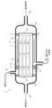
- FIG. 5 is a see-through side view of the reactor module 2.
- the reactor module 2 includes the above-described monolithic reactor 1 , housing 3 , annular first sealing portion 4 , annular second sealing portion 5 and annular flow stop portion 6 .
- the housing 3 is made of, for example, a metal material (such as stainless steel). Housing 3 accommodates reactor 1 therein.
- the housing 3 has a sweep gas supply port 3a, a sweep gas discharge port 3b, a source gas supply port 3c and a liquid fuel discharge port 3d.
- the interior of the housing 3 is partitioned into first to fourth spaces P1 to P4 by the first sealing portion 4, the second sealing portion 5 and the flow stop portion 6. As shown in FIG.
- the first space P1 is a space between the first sealing portion 4 and the flow stop portion 6.
- a sweep gas inlet d1 formed in the side surface S3 of the reactor 1 opens into the first space P1.
- a sweep gas supply port 3a for supplying a sweep gas to the first space P1 opens in the first space P1.
- a second space P ⁇ b>2 is a space between the second sealing portion 5 and the flow stop portion 6 .
- a sweep gas outlet d2 formed in the side surface S3 of the reactor 1 opens into the second space P2.
- a sweep gas discharge port 3b for discharging the sweep gas from the second space P2 opens in the second space P2.
- the first space P ⁇ b>1 and the second space P ⁇ b>2 are separated by the flow stopper 6 .
- a raw material gas supply port 3c for supplying raw material gas to the third space P3 opens in the third space P3.
- a raw material gas inlet e1 (see FIG. 4) formed in the first end surface S1 of the reactor 1 opens into the third space P3.
- a liquid fuel outlet 3d for discharging the liquid fuel from the fourth space P4 opens in the fourth space P4.
- a liquid fuel outlet e2 (see FIG. 4) formed in the second end surface S2 of the reactor 1 opens into the fourth space P4.
- the first space P ⁇ b>1 and the third space P ⁇ b>3 are separated by the first sealing portion 4
- the second space P ⁇ b>2 and the fourth space P ⁇ b>4 are separated by the second sealing portion 5 .
- the first sealing portion 4 is formed in an annular shape.
- the first sealing part 4 fixes the first end 1 a of the reactor 1 to the housing 3 .
- the first sealing portion 4 is connected to the side surface S ⁇ b>3 of the reactor 1 and the inner surface T ⁇ b>1 of the housing 3 .
- the first sealing portion 4 seals between the first end portion 1 a of the reactor 1 and the housing 3 .
- Examples of the constituent material of the first sealing portion 4 include glass, silver solder, solder, inorganic adhesives, and the like.
- the second sealing portion 5 is formed in an annular shape.
- the second sealing portion 5 secures the second end 1 b of the reactor 1 to the housing 3 .
- the second sealing portion 5 is connected to the side surface S ⁇ b>3 of the reactor 1 and the inner surface T ⁇ b>1 of the housing 3 . Since the fourth space P4 side of the second sealing portion 5 is exposed to the high-temperature liquid fuel and water vapor, the resistance to the chemical load of the high-temperature liquid fuel and the resistance to water vapor are the constituent materials of the second sealing portion 5. is required.
- the constituent material of the second sealing portion 5 include glass, silver solder, solder, inorganic adhesives, and the like. Rubber and plastic are not suitable materials for the second sealing portion 5 .
- the flow stop portion 6 is formed in an annular shape.
- the flow stop portion 6 is arranged between the first sealing portion 4 and the second sealing portion 5 in the longitudinal direction.
- the flow stopper 6 separates the first space P1 and the second space P2.
- the flow stop portion 6 is formed in an annular shape.
- a flow stop 6 is arranged between the reactor 1 and the housing 3 .
- the flow stopper 6 is arranged between the first space P1 and the second space P2.
- the flow stopper 6 prevents the sweep gas from flowing from the first space P1 to the second space P2.
- the flow stopper 6 only needs to be able to suppress the flow of the sweep gas, and does not have to seal the space between the reactor 1 and the housing 3 .
- the flow stopper 6 can be made of, for example, expanded graphite, rubber, resin, or the like.
- the sweep gas is supplied to the first space P1 from the sweep gas supply port 3a.
- the sweep gas flows into the second flow path 12 from the inlet d1 of the reactor 1 .
- the sweep gas that has taken in water vapor and absorbed reaction heat in the second flow path 12 flows out from the outlet d2 of the reactor 1 into the second space P2.
- the sweep gas that has flowed out from the outlet d2 into the second space P2 flows through the second space P2 from the outlet d2 toward the sweep gas discharge port 3b.
- the sweep gas that has passed through the second space P2 is discharged to the outside from the sweep gas outlet 3b.
- the reactor 1 can be cooled from the inside by the sweep gas flowing through the second flow path 12, and the reactor 1 can be cooled from the outside by the sweep gas flowing through the second space P2. Therefore, the reaction heat generated by the conversion reaction can be removed efficiently, so that the conversion efficiency can be further improved.
- the direction of the sweep gas flowing in the second space P2 is opposite to the direction of the sweep gas flowing in the second flow path 12 when the reactor 1 is viewed from the side. Therefore, since the entire amount of the sweep gas can flow outside the reactor 1, heat can be transported and dispersed by a large amount of the sweep gas. Therefore, it is possible to achieve both heat removal from the outside and heat equalization.
- the flow rate of the sweep gas flowing outside the reactor 1 is large and the pressure loss from the outflow port d2 to the sweep gas discharge port 3b increases, the flow rate distribution of the sweep gas flowing inside the reactor 1 should be uniform. can be done. Therefore, it is possible to achieve both heat removal from the inside and heat equalization.
- the sweep gas supply port 3a and the sweep gas discharge port 3b formed in the housing 3 are arranged on a straight line that intersects the axis of the reactor 1 in cross-sectional view.
- the flow path lengths of the sweep gas flowing from the sweep gas supply port 3a to the sweep gas discharge port 3b through the second flow paths 12 can be made equal, so that the flow of the sweep gas can be prevented from becoming biased.
- the positional relationship between the sweep gas supply port 3a and the sweep gas discharge port 3b can be changed as appropriate.
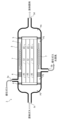
- the reactor module 2 may further include a heat exchanger that cools the sweep gas flowing through the second space P2.
- the reactor module 2 may include a heat exchanger 7 arranged inside the second space P2.
- the reactor module 2 may have a heat exchanger 8 arranged outside the second space P2.
- the heat exchangers 7 and 8 for example, refrigerant heat exchangers can be used.
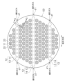
- FIG. 8 is a cross-sectional view of the reactor module 2 shown in FIG. In FIG. 8, a cross section perpendicular to the axis of the reactor 1 is illustrated.
- the first extension direction in which the outflow slit 15 extends inside the reactor 1 is inclined or orthogonal to the discharge direction of the sweep gas discharged to the outside from the sweep gas discharge port 3b.
- the angle ⁇ 1 of the first extending direction with respect to the discharge direction is preferably 45 degrees or more and 135 degrees or less.
- FIG. 9 is a cross-sectional view of the reactor module 2 shown in FIG. In FIG. 9, a cross section perpendicular to the axis of the reactor 1 is illustrated.
- the second extending direction in which the inflow slit 14 extends inside the reactor 1 is preferably inclined or orthogonal to the supply direction of the sweep gas supplied from the sweep gas supply port 3a.
- the angle ⁇ 2 of the second extending direction with respect to the supply direction is preferably 45 degrees or more and 135 degrees or less.
- the separation membrane 30 is configured to allow water vapor, which is one of the products of the conversion reaction from the source gas to the liquid fuel, to permeate therethrough, but the invention is not limited to this.
- the separation membrane 30 may permeate the liquid fuel itself produced by the conversion reaction from the source gas to the liquid fuel. Also in this case, the reaction equilibrium of the above formula (1) can be shifted to the product side.
- the separation membrane 30 is permeable to the liquid fuel, even when the liquid fuel is generated by a reaction that does not generate water vapor (eg, H 2 +CO ⁇ CH 3 OH), the reaction equilibrium is shifted to the product side. be able to.
- a reaction that does not generate water vapor eg, H 2 +CO ⁇ CH 3 OH
- Modification 4 In the above embodiments, a reactor module including a reactor was described, but the present invention is also applicable to a separation membrane module including a separation filter.
- the separation filter has the same configuration as the reactor 1 according to the above embodiment except that it has a separation membrane for separating a predetermined component from the mixed fluid.
- the temperature of the sweep gas is lower than the operating temperature of the reactor 1, but in the separation membrane module, if the separation membrane is to be cooled, the temperature of the sweep gas must be lower than the temperature of the separation filter. In order to heat the separation membrane, the temperature of the sweep gas must be higher than the temperature of the separation filter.
- the separation membrane module may further include a heat exchanger (see FIGS. 6 and 7) that cools or heats the sweep gas flowing through the second space P2.
- a refrigerant heat exchanger is used to cool the sweep gas flowing through the second space P2
- a heat medium heat exchanger is used to heat the sweep gas flowing through the second space P2. .
Landscapes
- Chemical & Material Sciences (AREA)
- Organic Chemistry (AREA)
- Chemical Kinetics & Catalysis (AREA)
- Engineering & Computer Science (AREA)
- Oil, Petroleum & Natural Gas (AREA)
- Water Supply & Treatment (AREA)
- General Chemical & Material Sciences (AREA)
- Separation Using Semi-Permeable Membranes (AREA)
- Organic Low-Molecular-Weight Compounds And Preparation Thereof (AREA)
- Liquid Carbonaceous Fuels (AREA)
Priority Applications (6)
| Application Number | Priority Date | Filing Date | Title |
|---|---|---|---|
| AU2022439903A AU2022439903B2 (en) | 2022-02-08 | 2022-11-30 | Reactor module, method for synthesizing liquid fuel, separation membrane module and separation method |
| EP22926070.8A EP4303206A4 (en) | 2022-02-08 | 2022-11-30 | REACTOR MODULE, LIQUID FUEL SYNTHESIS METHOD, SEPARATION MEMBRANE MODULE AND SEPARATION METHOD |
| CN202280029745.3A CN117242048A (zh) | 2022-02-08 | 2022-11-30 | 反应器模块、液体燃料合成方法、分离膜模块及分离方法 |
| JP2023552324A JP7419610B2 (ja) | 2022-02-08 | 2022-11-30 | リアクタモジュール、液体燃料合成方法、分離膜モジュール及び分離方法 |
| US18/474,352 US20240017237A1 (en) | 2022-02-08 | 2023-09-26 | Reactor module, liquid fuel synthesis method, separation membrane module, and separation method |
| JP2024002055A JP2024032764A (ja) | 2022-02-08 | 2024-01-10 | リアクタモジュール、液体燃料合成方法、分離膜モジュール及び分離方法 |
Applications Claiming Priority (4)
| Application Number | Priority Date | Filing Date | Title |
|---|---|---|---|
| JP2022017959 | 2022-02-08 | ||
| JP2022-017959 | 2022-02-08 | ||
| JP2022134440 | 2022-08-25 | ||
| JP2022-134440 | 2022-08-25 |
Related Child Applications (1)
| Application Number | Title | Priority Date | Filing Date |
|---|---|---|---|
| US18/474,352 Continuation US20240017237A1 (en) | 2022-02-08 | 2023-09-26 | Reactor module, liquid fuel synthesis method, separation membrane module, and separation method |
Publications (1)
| Publication Number | Publication Date |
|---|---|
| WO2023153054A1 true WO2023153054A1 (ja) | 2023-08-17 |
Family
ID=87564140
Family Applications (1)
| Application Number | Title | Priority Date | Filing Date |
|---|---|---|---|
| PCT/JP2022/044168 Ceased WO2023153054A1 (ja) | 2022-02-08 | 2022-11-30 | リアクタモジュール、液体燃料合成方法、分離膜モジュール及び分離方法 |
Country Status (5)
| Country | Link |
|---|---|
| US (1) | US20240017237A1 (https=) |
| EP (1) | EP4303206A4 (https=) |
| JP (2) | JP7419610B2 (https=) |
| AU (1) | AU2022439903B2 (https=) |
| WO (1) | WO2023153054A1 (https=) |
Citations (2)
| Publication number | Priority date | Publication date | Assignee | Title |
|---|---|---|---|---|
| WO2010134514A1 (ja) * | 2009-05-18 | 2010-11-25 | 日本碍子株式会社 | セラミック浸透気化膜及びセラミック蒸気透過膜 |
| JP2018008940A (ja) | 2016-07-04 | 2018-01-18 | 公益財団法人地球環境産業技術研究機構 | メタノール製造方法およびメタノール製造装置 |
Family Cites Families (3)
| Publication number | Priority date | Publication date | Assignee | Title |
|---|---|---|---|---|
| US7169213B2 (en) * | 2004-10-29 | 2007-01-30 | Corning Incorporated | Multi-channel cross-flow porous device |
| JP7076229B2 (ja) * | 2018-03-08 | 2022-05-27 | Jfeスチール株式会社 | 二酸化炭素の再利用方法 |
| JP6707169B1 (ja) * | 2019-10-03 | 2020-06-10 | 川崎重工業株式会社 | ガス分離膜モジュール |
-
2022
- 2022-11-30 EP EP22926070.8A patent/EP4303206A4/en active Pending
- 2022-11-30 WO PCT/JP2022/044168 patent/WO2023153054A1/ja not_active Ceased
- 2022-11-30 AU AU2022439903A patent/AU2022439903B2/en active Active
- 2022-11-30 JP JP2023552324A patent/JP7419610B2/ja active Active
-
2023
- 2023-09-26 US US18/474,352 patent/US20240017237A1/en active Pending
-
2024
- 2024-01-10 JP JP2024002055A patent/JP2024032764A/ja active Pending
Patent Citations (2)
| Publication number | Priority date | Publication date | Assignee | Title |
|---|---|---|---|---|
| WO2010134514A1 (ja) * | 2009-05-18 | 2010-11-25 | 日本碍子株式会社 | セラミック浸透気化膜及びセラミック蒸気透過膜 |
| JP2018008940A (ja) | 2016-07-04 | 2018-01-18 | 公益財団法人地球環境産業技術研究機構 | メタノール製造方法およびメタノール製造装置 |
Non-Patent Citations (2)
| Title |
|---|
| IND. ENG. CHEM. RES., vol. 40, 2001, pages 163 - 175 |
| See also references of EP4303206A4 |
Also Published As
| Publication number | Publication date |
|---|---|
| JP7419610B2 (ja) | 2024-01-22 |
| EP4303206A1 (en) | 2024-01-10 |
| JP2024032764A (ja) | 2024-03-12 |
| EP4303206A4 (en) | 2024-10-02 |
| US20240017237A1 (en) | 2024-01-18 |
| JPWO2023153054A1 (https=) | 2023-08-17 |
| AU2022439903B2 (en) | 2025-02-27 |
| AU2022439903A1 (en) | 2023-10-12 |
Similar Documents
| Publication | Publication Date | Title |
|---|---|---|
| US20240017236A1 (en) | Reactor module, liquid fuel synthesis method, separation membrane module, and separation method | |
| JP7559190B2 (ja) | 分離膜モジュール | |
| JP7245585B1 (ja) | リアクタ及び液体燃料合成方法 | |
| JP7419610B2 (ja) | リアクタモジュール、液体燃料合成方法、分離膜モジュール及び分離方法 | |
| JP7612879B2 (ja) | リアクタ及び液体燃料合成方法 | |
| JP7853401B2 (ja) | リアクタモジュール及び分離膜モジュール | |
| JP7797193B2 (ja) | リアクタ及び液体燃料合成方法 | |
| CN117242048A (zh) | 反应器模块、液体燃料合成方法、分离膜模块及分离方法 | |
| JP7853755B2 (ja) | 分離膜モジュール | |
| JP7650376B2 (ja) | 分離膜モジュール | |
| JP7577242B2 (ja) | 膜モジュール | |
| CN117177803A (zh) | 反应器模块、液体燃料合成方法、分离膜模块及分离方法 | |
| CN117043129A (zh) | 反应器以及液体燃料合成方法 | |
| CN118317827A (zh) | 分离膜组件 | |
| WO2024029569A1 (ja) | 分離膜モジュール | |
| CN119013091A (zh) | 膜组件和分离膜模块 |
Legal Events
| Date | Code | Title | Description |
|---|---|---|---|
| WWE | Wipo information: entry into national phase |
Ref document number: 2023552324 Country of ref document: JP |
|
| 121 | Ep: the epo has been informed by wipo that ep was designated in this application |
Ref document number: 22926070 Country of ref document: EP Kind code of ref document: A1 |
|
| WWE | Wipo information: entry into national phase |
Ref document number: AU2022439903 Country of ref document: AU Ref document number: 2022439903 Country of ref document: AU Ref document number: 22926070 Country of ref document: EP |
|
| WWE | Wipo information: entry into national phase |
Ref document number: 2022926070 Country of ref document: EP |
|
| ENP | Entry into the national phase |
Ref document number: 2022926070 Country of ref document: EP Effective date: 20231005 |
|
| ENP | Entry into the national phase |
Ref document number: 2022439903 Country of ref document: AU Date of ref document: 20221130 Kind code of ref document: A |
|
| WWE | Wipo information: entry into national phase |
Ref document number: 202280029745.3 Country of ref document: CN |
|
| NENP | Non-entry into the national phase |
Ref country code: DE |