WO2023153024A1 - サーボ記録装置、サーボライトヘッド、磁気テープの製造方法及び磁気テープ - Google Patents
サーボ記録装置、サーボライトヘッド、磁気テープの製造方法及び磁気テープ Download PDFInfo
- Publication number
- WO2023153024A1 WO2023153024A1 PCT/JP2022/038907 JP2022038907W WO2023153024A1 WO 2023153024 A1 WO2023153024 A1 WO 2023153024A1 JP 2022038907 W JP2022038907 W JP 2022038907W WO 2023153024 A1 WO2023153024 A1 WO 2023153024A1
- Authority
- WO
- WIPO (PCT)
- Prior art keywords
- servo
- magnetic tape
- write head
- angle
- width direction
- Prior art date
- Legal status (The legal status is an assumption and is not a legal conclusion. Google has not performed a legal analysis and makes no representation as to the accuracy of the status listed.)
- Ceased
Links
Images


Classifications
-
- G—PHYSICS
- G11—INFORMATION STORAGE
- G11B—INFORMATION STORAGE BASED ON RELATIVE MOVEMENT BETWEEN RECORD CARRIER AND TRANSDUCER
- G11B5/00—Recording by magnetisation or demagnetisation of a record carrier; Reproducing by magnetic means; Record carriers therefor
- G11B5/74—Record carriers characterised by the form, e.g. sheet shaped to wrap around a drum
- G11B5/78—Tape carriers
-
- G—PHYSICS
- G11—INFORMATION STORAGE
- G11B—INFORMATION STORAGE BASED ON RELATIVE MOVEMENT BETWEEN RECORD CARRIER AND TRANSDUCER
- G11B21/00—Head arrangements not specific to the method of recording or reproducing
- G11B21/02—Driving or moving of heads
- G11B21/10—Track finding or aligning by moving the head ; Provisions for maintaining alignment of the head relative to the track during transducing operation, i.e. track following
-
- G—PHYSICS
- G11—INFORMATION STORAGE
- G11B—INFORMATION STORAGE BASED ON RELATIVE MOVEMENT BETWEEN RECORD CARRIER AND TRANSDUCER
- G11B5/00—Recording by magnetisation or demagnetisation of a record carrier; Reproducing by magnetic means; Record carriers therefor
- G11B5/127—Structure or manufacture of heads, e.g. inductive
- G11B5/187—Structure or manufacture of the surface of the head in physical contact with, or immediately adjacent to the recording medium; Pole pieces; Gap features
-
- G—PHYSICS
- G11—INFORMATION STORAGE
- G11B—INFORMATION STORAGE BASED ON RELATIVE MOVEMENT BETWEEN RECORD CARRIER AND TRANSDUCER
- G11B5/00—Recording by magnetisation or demagnetisation of a record carrier; Reproducing by magnetic means; Record carriers therefor
- G11B5/127—Structure or manufacture of heads, e.g. inductive
- G11B5/29—Structure or manufacture of unitary devices formed of plural heads for more than one track
- G11B5/295—Manufacture
-
- G—PHYSICS
- G11—INFORMATION STORAGE
- G11B—INFORMATION STORAGE BASED ON RELATIVE MOVEMENT BETWEEN RECORD CARRIER AND TRANSDUCER
- G11B5/00—Recording by magnetisation or demagnetisation of a record carrier; Reproducing by magnetic means; Record carriers therefor
- G11B5/127—Structure or manufacture of heads, e.g. inductive
- G11B5/31—Structure or manufacture of heads, e.g. inductive using thin films
-
- G—PHYSICS
- G11—INFORMATION STORAGE
- G11B—INFORMATION STORAGE BASED ON RELATIVE MOVEMENT BETWEEN RECORD CARRIER AND TRANSDUCER
- G11B5/00—Recording by magnetisation or demagnetisation of a record carrier; Reproducing by magnetic means; Record carriers therefor
- G11B5/48—Disposition or mounting of heads or head supports relative to record carriers ; arrangements of heads, e.g. for scanning the record carrier to increase the relative speed
- G11B5/58—Disposition or mounting of heads or head supports relative to record carriers ; arrangements of heads, e.g. for scanning the record carrier to increase the relative speed with provision for moving the head for the purpose of maintaining alignment of the head relative to the record carrier during transducing operation, e.g. to compensate for surface irregularities of the latter or for track following
- G11B5/584—Disposition or mounting of heads or head supports relative to record carriers ; arrangements of heads, e.g. for scanning the record carrier to increase the relative speed with provision for moving the head for the purpose of maintaining alignment of the head relative to the record carrier during transducing operation, e.g. to compensate for surface irregularities of the latter or for track following for track following on tapes
- G11B5/588—Disposition or mounting of heads or head supports relative to record carriers ; arrangements of heads, e.g. for scanning the record carrier to increase the relative speed with provision for moving the head for the purpose of maintaining alignment of the head relative to the record carrier during transducing operation, e.g. to compensate for surface irregularities of the latter or for track following for track following on tapes by controlling the position of the rotating heads
- G11B5/592—Disposition or mounting of heads or head supports relative to record carriers ; arrangements of heads, e.g. for scanning the record carrier to increase the relative speed with provision for moving the head for the purpose of maintaining alignment of the head relative to the record carrier during transducing operation, e.g. to compensate for surface irregularities of the latter or for track following for track following on tapes by controlling the position of the rotating heads using bimorph elements supporting the heads
- G11B5/5921—Disposition or mounting of heads or head supports relative to record carriers ; arrangements of heads, e.g. for scanning the record carrier to increase the relative speed with provision for moving the head for the purpose of maintaining alignment of the head relative to the record carrier during transducing operation, e.g. to compensate for surface irregularities of the latter or for track following for track following on tapes by controlling the position of the rotating heads using bimorph elements supporting the heads using auxiliary signals, e.g. pilot signals
- G11B5/5926—Disposition or mounting of heads or head supports relative to record carriers ; arrangements of heads, e.g. for scanning the record carrier to increase the relative speed with provision for moving the head for the purpose of maintaining alignment of the head relative to the record carrier during transducing operation, e.g. to compensate for surface irregularities of the latter or for track following for track following on tapes by controlling the position of the rotating heads using bimorph elements supporting the heads using auxiliary signals, e.g. pilot signals recorded in separate tracks, e.g. servo tracks
- G11B5/5928—Longitudinal tracks
-
- G—PHYSICS
- G11—INFORMATION STORAGE
- G11B—INFORMATION STORAGE BASED ON RELATIVE MOVEMENT BETWEEN RECORD CARRIER AND TRANSDUCER
- G11B5/00—Recording by magnetisation or demagnetisation of a record carrier; Reproducing by magnetic means; Record carriers therefor
- G11B5/62—Record carriers characterised by the selection of the material
- G11B5/68—Record carriers characterised by the selection of the material comprising one or more layers of magnetisable material homogeneously mixed with a bonding agent
- G11B5/70—Record carriers characterised by the selection of the material comprising one or more layers of magnetisable material homogeneously mixed with a bonding agent on a base layer
- G11B5/706—Record carriers characterised by the selection of the material comprising one or more layers of magnetisable material homogeneously mixed with a bonding agent on a base layer characterised by the composition of the magnetic material
- G11B5/70626—Record carriers characterised by the selection of the material comprising one or more layers of magnetisable material homogeneously mixed with a bonding agent on a base layer characterised by the composition of the magnetic material containing non-metallic substances
- G11B5/70642—Record carriers characterised by the selection of the material comprising one or more layers of magnetisable material homogeneously mixed with a bonding agent on a base layer characterised by the composition of the magnetic material containing non-metallic substances iron oxides
- G11B5/70678—Ferrites
-
- G—PHYSICS
- G11—INFORMATION STORAGE
- G11B—INFORMATION STORAGE BASED ON RELATIVE MOVEMENT BETWEEN RECORD CARRIER AND TRANSDUCER
- G11B5/00—Recording by magnetisation or demagnetisation of a record carrier; Reproducing by magnetic means; Record carriers therefor
- G11B5/84—Processes or apparatus specially adapted for manufacturing record carriers
Definitions
- This technology relates to technologies such as servo recording devices that record servo patterns on magnetic tape.
- a magnetic tape is provided with a plurality of data bands on which data is recorded and a plurality of servo bands on which servo patterns are recorded.
- a servo pattern is recorded on a servo band by a servo write head of a servo recording device (see, for example, Japanese Unexamined Patent Application Publication No. 2002-200016).
- the data write head of the data recording device writes data to any position of the data band while recognizing the position of the magnetic tape based on the servo pattern (see, for example, Patent Document 2 below).
- the width of the magnetic tape may fluctuate depending on temperature, humidity, etc.
- Japanese Patent Application Laid-Open No. 2002-200000 proposes to arrange the data write head so as to be inclined with respect to the width direction of the magnetic tape.
- the purpose of the present technology is to provide a technology for writing servo patterns that can be read accurately even when the data write head is arranged tilted with respect to the width direction of the magnetic tape. to do.
- a servo recording device includes a servo write head.
- the plurality of servo bands of the magnetic tape used in a data recording apparatus including a data write head in which the servo write head is arranged such that its longitudinal direction is inclined at a first head azimuth angle with respect to the width direction of the magnetic tape.
- a first servo pattern and a second servo pattern which are asymmetric with respect to the width direction of the magnetic tape, are respectively written.
- the servo write head has a first servo element for writing the first servo pattern and a second servo element for writing the second servo pattern. There may be corresponding pairs of servo elements.
- the first servo element and the second servo element may be provided in the servo write head so as to be asymmetric with respect to the width direction of the magnetic tape.
- the first servo element is inclined at a first angle with respect to the width direction of the magnetic tape
- the second servo element is inclined with respect to the width direction of the magnetic tape. It may be tilted at a second angle different from the first angle, opposite to the first angle.
- the first head azimuth angle of the data write head of the data recording device may be adjusted.
- the first head azimuth angle of the data write head in the data recording device may be adjusted within a reference angle ⁇ x°.
- the first angle and the second angle may be related to the reference angle.
- the first angle may be a value obtained by adding a servo azimuth angle to the reference angle.
- the second angle may be a value obtained by subtracting the servo azimuth angle from the reference angle.
- the servo write head may be arranged such that its longitudinal direction is inclined at a second head azimuth angle with respect to the width direction of the magnetic tape.
- the first servo element and the second servo element may be inclined at the same angle in opposite directions with respect to the longitudinal direction of the servo write head.
- the second head azimuth angle may match the reference angle.
- the first servo element and the second servo element each have a longitudinal direction, and the length in the longitudinal direction of the first servo element is the length in the longitudinal direction of the second servo element. may be different from the length in
- the component in the width direction of the magnetic tape in the length of the first servo element and the component in the width direction of the magnetic tape in the length of the second servo element are the same.
- the servo write head has a width direction, the servo write head has a facing surface facing the magnetic tape, and the facing surface is non-parallel to the width direction of the servo write head. It may include a plurality of grooves along any direction.
- the reference angle may be 2.5° or more with respect to the width direction of the magnetic tape.
- the value of x may be 0.7° or less.
- the first servo pattern and the second servo pattern are included, where Ref ⁇ is the reference angle and SP is the pitch of the adjacent servo bands in the width direction of the magnetic tape.
- the phase difference of the servo pattern in servo bands adjacent to each other may be represented by SP ⁇ tan(Ref ⁇ ).
- a servo write head is used in a data recording device including a data write head arranged such that its longitudinal direction is inclined at a first head azimuth angle with respect to the width direction of the magnetic tape.
- a first servo pattern and a second servo pattern, which are asymmetrical with respect to the width direction of the magnetic tape, are respectively written in the servo bands of .
- a magnetic tape manufacturing method is the magnetic tape used in a data recording device including a data write head arranged such that its longitudinal direction is inclined at a first head azimuth angle with respect to the width direction of the magnetic tape.
- a servo write head of a servo recording device writes a first servo pattern and a second servo pattern that are asymmetric with respect to the width direction of the magnetic tape, respectively, on the plurality of servo bands.
- a magnetic tape according to the present technology includes a base, a non-magnetic layer laminated on the base, and a magnetic layer laminated on the non-magnetic layer, Having a plurality of servo bands in which servo patterns including a first servo pattern and a second servo pattern asymmetric with respect to the width direction of the magnetic tape are written,
- the servo patterns in servo bands adjacent to each other have a phase difference.
- the first servo pattern is inclined at a first angle with respect to the width direction of the magnetic tape
- the second servo pattern is inclined at the first angle with respect to the width direction of the magnetic tape. It may be inclined at a second angle different from the first angle, opposite to the first angle.
- the first servo pattern and the second servo pattern each have a longitudinal direction, and the length in the longitudinal direction of the first servo pattern and the length in the longitudinal direction of the second servo pattern It can be different than the length.
- the magnetic tape may be used in a data recording device including a data write head arranged such that its longitudinal direction is inclined at a first head azimuth angle with respect to the width direction of the magnetic tape.
- the first head azimuth angle may be adjusted within a predetermined range with reference to a reference angle.
- the phase difference may be related to a reference angle.
- the phase difference can be expressed by SP ⁇ tan(Ref ⁇ ). good.
- the phases of the servo patterns may be the same in the direction of the reference angle with respect to the width direction of the magnetic tape.
- the first angle and the second angle may be related to the reference angle.
- the first angle may be a value obtained by adding a servo azimuth angle to the reference angle.
- the second angle may be a value obtained by subtracting the servo azimuth angle from the reference angle.
- FIG. 3 is a schematic diagram of the magnetic tape as viewed from the side;
- FIG. 2 is a schematic view of the magnetic tape as viewed from above (magnetic layer side); 1 is a diagram showing a data recording/reproducing device;
- FIG. 4 is a schematic view of the data write head viewed from below (back layer side);
- FIG. 4 is a diagram showing the relationship between the angular range Ref ⁇ x° of the azimuth angle of the data write head and the azimuth loss L ⁇ (recording wavelength: 0.1 ⁇ m).
- 6 is a diagram showing the relationship between the angular range Ref ⁇ x° at the azimuth angle ⁇ of the data write head and the correction amount for the servo band pitch difference based on the width variation of the magnetic tape 1;
- FIG. 3 is a schematic diagram of the magnetic tape as viewed from the side
- FIG. 2 is a schematic view of the magnetic tape as viewed from above (magnetic layer side)
- 1 is a diagram showing a data recording
- FIG. 10 is a diagram showing a correction amount for a servo band pitch difference based on width variation of a magnetic tape
- FIG. 4 is a diagram showing the relationship between the angle range Ref ⁇ x° of the azimuth angle ⁇ of the data write head and the azimuth loss L ⁇ (recording wavelength: 0.07 ⁇ m).
- BRIEF DESCRIPTION OF THE DRAWINGS It is a figure which shows the servo recording/reproducing apparatus which concerns on 1st Embodiment of this technique.
- FIG. 4 is a diagram showing a servo write head according to the first embodiment and a pulse signal input to the servo write head; 4 is an enlarged view of a servo element included in the servo write head according to the first embodiment;
- FIG. 4 is a diagram showing a servo write head according to the first embodiment and a pulse signal input to the servo write head; 4 is an enlarged view of a servo element included in the servo write head according to the
- FIG. 5 is a diagram showing how a servo pattern is written on a magnetic tape by the servo write head according to the first embodiment
- FIG. 8 is an enlarged view of a servo write head according to a second embodiment and a servo element included in the servo write head
- FIG. 10 is a diagram showing how a servo pattern is written on a magnetic tape by the servo write head according to the second embodiment
- FIG. 10 is a diagram showing the servo write head with reference to the coordinate system of the servo write head in the second embodiment
- FIG. 10 is a diagram showing a state in which the facing surface of the servo write head is subjected to low-friction processing
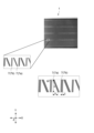
- FIG. 10 is a diagram showing how a servo pattern is read by the servo read section of the data write head in the first comparative example, the second comparative example, and the present embodiment
- FIG. 14 is an enlarged view of the drawing on the right side of FIG. 13, showing an example of specific dimensions of the first servo element and the second servo element (based on the XYZ coordinate system)
- FIG. 16 is an enlarged view of the drawing on the right side of FIG. 15, showing an example of specific dimensions of the first servo element and the second servo element (based on the X′′Y′′Z′′ coordinate system);
- FIG. 2 is a diagram showing a first example of a method for checking whether a magnetic tape is a magnetic tape used in a data write head tilt type data recording/reproducing apparatus
- FIG. 5 is a diagram showing a second example of a method for confirming whether a magnetic tape is a magnetic tape used in a data write head tilt type data recording/reproducing apparatus
- the servo recording/reproducing device 101 (servo recording device) (see FIG. 9) can accurately read by the data write head 20 of the data recording/reproducing device 100 (data recording device) (see FIG. 3). servo pattern 7 on the servo band s of the magnetic tape 1 (see FIG. 2).
- the data write head 20 of the data recording/reproducing device 100 is arranged obliquely with respect to the width direction of the magnetic tape 1 (see FIG. 4). Therefore, in this embodiment, the first servo pattern 7a ("/") and the first servo pattern 7b (" ⁇ ") that are asymmetric with respect to the width direction of the magnetic tape are written in the servo band s (Fig. 2).
- the configuration of the magnetic tape 1, the configuration of the data recording/reproducing device 100, and the configuration of the servo recording/reproducing device 101 will be described in this order.
- FIG. 1 is a schematic view of the magnetic tape 1 viewed from the side
- FIG. 2 is a schematic view of the magnetic tape 1 viewed from above (the side of the magnetic layer 4).
- the magnetic tape 1 is long in the longitudinal direction (X-axis direction), short in the width direction (Y-axis direction), and thin in the thickness direction (Z-axis direction). ing.
- the width (in the Y-axis direction) of the magnetic tape 1 is typically about 1/2 inch, but the width of the magnetic tape 1 may be about 1 inch, and the size may be changed as appropriate. It is possible.
- the magnetic tape 1 includes a tape-shaped substrate 2 elongated in the longitudinal direction (X-axis direction), an underlayer 3 (non-magnetic layer) provided on one main surface of the substrate 2, and It includes a magnetic layer 4 provided and a back layer 5 provided on the other main surface of the substrate 2 .
- the back layer 5 may be provided as necessary, and the back layer 5 may be omitted.
- the magnetic layer 4 may be vertically oriented or longitudinally oriented. Further, the magnetic layer 4 may be a coated film of a magnetic material, or may be a deposited film or a sputtered film of a magnetic material. Details of each layer constituting the magnetic tape 1 will be described later.
- the magnetic layer 4 includes a plurality of data bands d (data bands d0 to d3) in which data are written and a plurality of servo bands s (servo bands s0 to s4) in which servo patterns 7 are written.
- the plurality of data bands d and the plurality of servo bands s each have a shape that is long in the longitudinal direction (X-axis direction) and short in the width direction (Y-axis direction).
- the servo bands s are arranged at positions sandwiching the data bands d in the width direction (Y-axis direction).
- the number of data bands d is four and the number of servo bands s is five.
- the number of data bands d and the number of servo bands s can be changed as appropriate.
- the ratio of the area of the servo band s to the area of the entire surface of the magnetic layer 4 is, for example, 4.0% or less.
- the width of the servo band s is 1/2 inch tape width, for example, 96 ⁇ m or less.
- the ratio of the area of the servo band s to the area of the entire surface of the magnetic layer 43 can be obtained, for example, by developing the magnetic tape 1 using a developer such as a ferricolloid developer, and then observing the developed magnetic tape 1 with an optical microscope. It can be measured by observation.
- the data band d includes a plurality of recording tracks 6 that are long in the longitudinal direction and aligned in the width direction.
- the number of recording tracks 6 included in one data band d is, for example, approximately 1,000 to 2,500. Data is recorded within the recording track 6 along this recording track 6 .
- One bit length in the longitudinal direction of the data recorded in the data band d is, for example, 48 nm or less.
- the width of the recording track 6 (track pitch: Y-axis direction) is, for example, 2.0 ⁇ m or less. Note that such a recording track width can be obtained, for example, by developing the magnetic layer 4 of the magnetic tape 1 using a developing solution such as a ferricolloid developing solution, and then observing the developed magnetic layer 4 of the magnetic tape 1 with an optical microscope. It can be measured by observation.
- a method using a data write head 20 may be used as a method for measuring the recording track width.
- the data write head 20 in order to ignore fluctuations during running of the magnetic tape 1, the data write head 20 is placed in the recording and reproduction states, and the recording track width is measured from the output change when the azimuth angle ⁇ of the data write head 20 is changed. can be done.
- IEEE_Sept1996_Crosstrack Profiles of Thin Film MR Tape Heads Using the Azimuth Displacement Method IEEE_Sept1996_Crosstrack Profiles of Thin Film MR Tape Heads Using the Azimuth Displacement Method
- the servo band s includes a servo pattern 7 having a predetermined shape recorded by a servo recording/reproducing device 101 (see FIG. 9), which will be described later.
- the servo patterns 7 include a first servo pattern 7a ("/") and a second servo pattern 7b (" ⁇ ").
- the symbols "/" and “ ⁇ ” in the first servo pattern 7a and the second servo pattern 7b refer to the servo pattern when the magnetic tape 1 is viewed from below (back layer side). It is used as a code indicating the direction of inclination of the pattern. Therefore, the signs of "/" and " ⁇ ” in the first servo pattern 7a and the second servo pattern 7b are opposite to those seen from the magnetic layer side in FIG. On the other hand, in FIGS.
- the first servo element 42a (“/”) for writing the first servo pattern 7a (“/”) and the second servo pattern 7b (
- the second servo element 42b (“ ⁇ ") for writing " ⁇ ") and the servo patterns 7a, 7b recorded on the magnetic layers by the servo elements 42a, 42b are shown as viewed from the back layer side.
- the first servo pattern 7a (“/”) and the second servo pattern 7b (“ ⁇ ”) are arranged so as to be asymmetric with respect to the width direction (Y-axis direction) of the magnetic tape 1. written in band s.
- the first servo pattern 7a (“/”) and the second servo pattern 7b (“ ⁇ ”) are symmetrical (line symmetrical) with respect to the width direction of the magnetic tape 1. is written in the servo band s.
- the first servo pattern 7a (“/”) is inclined at a first angle ⁇ s1 with respect to the width direction of the magnetic tape 1
- the second servo pattern 7b (“ ⁇ ”) is inclined in the width direction of the magnetic tape 1. , at a second angle ⁇ s2 that is opposite to the first angle ⁇ s1 and different from the first angle ⁇ s1 (see FIGS. 11 and 13 described later).
- a group of first servo patterns 7 a (“/”) and a group of second servo patterns 7 (“ ⁇ ”) are alternately arranged in the longitudinal direction of the magnetic tape 1 .
- the number of first servo patterns 7a (“/") included in one group of first servo patterns 7a (“/”) is typically four or five.
- the number of second servo patterns 7b (“ ⁇ ") included in the second servo patterns 7b (“ ⁇ ") of is typically four or five.
- the magnetic layer 4 of the magnetic tape 1 is developed using a developing solution such as a ferricolloid developing solution, and then the magnetic layer 4 of the developed magnetic tape 1 is observed with an optical microscope. can be measured by
- the details of the first servo pattern 7a ("/") and the second servo pattern 7b (" ⁇ ") are described in the description of the servo write head 40 of the servo recording/reproducing apparatus 101 that writes this servo pattern 7. explain.
- the number of recording tracks 6 increases with each generation, and the recording capacity is dramatically improved.
- the number of recording tracks 6 in the original LTO-1 was 384, but the number of recording tracks 6 in LTO-2 to LTO-9 was 512, 704, 896, and 896, respectively. 1280, 2176, 3584 and 6656, 8960.
- the data recording capacity was 100 GB (gigabytes) for LTO-1, but 200 GB, 400 GB, 800 GB, 1.5 TB (terabytes), and 2.5 TB for LTO-2 to LTO-9 respectively. , 6.0 TB, 12 TB, and 18 TB.
- the number of recording tracks 6 and the recording capacity are not particularly limited, and can be changed as appropriate.
- the present technology is applied to a magnetic tape 1 that has a large number of recording tracks 6 and a large recording capacity (e.g., 6656 or more, 12 TB or more: LTO8 or later) and is susceptible to fluctuations in the width of the magnetic tape 1. It is advantageous if
- FIG. 3 is a diagram showing the data recording/reproducing apparatus 100. As shown in FIG. The data recording/reproducing apparatus 100 can record data on the magnetic tape 1 and reproduce the data recorded on the magnetic tape 1 .
- the data recording/reproducing device 100 is configured so that the cartridge 10 can be loaded.
- the cartridge 10 is configured so that the wound magnetic tape 1 can be rotatably accommodated therein.
- the data recording/reproducing apparatus 100 may be configured so that one cartridge 10 can be loaded, or multiple cartridges 10 can be loaded simultaneously.
- the data recording/reproducing device 100 includes a spindle 11, a take-up reel 12, a spindle driving device 13, a reel driving device 14, a data write head 20, a control device 15, a width measuring section 16, and an angle adjusting section 17. , and a plurality of guide rollers 18 .
- the spindle 11 is configured to be able to rotate the magnetic tape 1 housed inside the cartridge 10 by its rotation.
- the spindle driving device 13 rotates the spindle 11 according to a command from the control device 15 .
- the take-up reel 12 is configured so that the leading end of the magnetic tape 1 pulled out from the cartridge 10 via a tape loading mechanism (not shown) can be fixed.
- the reel driving device 14 rotates the take-up reel 12 according to a command from the control device 15 .
- a plurality of guide rollers 18 guide the travel of the magnetic tape 1 so that the transport path formed between the cartridge 10 and the take-up reel 12 has a predetermined relative positional relationship with respect to the data write head 20 .
- the data write head 20 writes data to the data band d (recording track 6) of the magnetic tape 1 according to a command from the control device 15 when the magnetic tape 1 passes under the data write head 20. can be recorded, and the recorded data can be reproduced.
- the running direction of the magnetic tape 1 is the forward direction indicated by arrow A1 in FIG. side) can be reciprocated.
- the data write head 20 is capable of recording/reproducing data in both the forward running direction and the reverse running direction of the magnetic tape 1 .
- the data write head 20 has the longitudinal direction (Y′-axis direction) of the data write head 20 with respect to the width direction (Y-axis direction) of the magnetic tape 1 at a predetermined angle ⁇ (first (head azimuth angle .theta.) is inclined (see FIG. 4, which will be described later).
- the angle at which the longitudinal direction (Y′-axis direction) of the data write head 20 is inclined with respect to the width direction (Y-axis direction) of the magnetic tape 1 is the azimuth angle ⁇ of the data write head 20 . call. Details of the configuration of the data write head 20 will be described later with reference to FIG. 4 and the like.
- the width measuring section 16 is configured to be able to measure the width of the magnetic tape 1 when the magnetic tape 1 passes under the width measuring section 16 .
- the width measuring section 16 is configured to be able to measure the width of the magnetic tape 1 when the data write head 20 records/reproduces data on/from the magnetic tape 1 .
- the width measuring unit 16 measures the width of the magnetic tape 1 and transmits it to the control device 15 .
- the width measurement unit 16 is composed of various sensors such as an optical sensor, for example. Any sensor that can measure the width of the magnetic tape 1 may be used as the width measuring unit 16 .
- the width of the magnetic tape 1 can also be predicted by reading adjacent servo patterns 7 and obtaining the difference between the position signals. In this case, the width measuring section 16 can be omitted.
- the angle adjuster 17 is configured to be able to hold the data write head 20 rotatably around the vertical axis (Z-axis).
- the angle adjuster 17 is configured to be able to adjust the azimuth angle ⁇ of the data write head 20 according to a command from the control device 15 .
- the control device 15 includes, for example, a control section, a storage section, a communication section, and the like.
- the control section is composed of, for example, a CPU (Central Processing Unit), etc., and comprehensively controls each section of the data recording/reproducing apparatus 100 according to a program stored in the storage section.
- CPU Central Processing Unit
- the storage unit includes a non-volatile memory in which various data and various programs are recorded, and a volatile memory used as a work area for the control unit.
- the various programs described above may be read from a portable recording medium such as an optical disk or a semiconductor memory, or may be downloaded from a server device on a network.
- the communication unit is configured to be able to communicate with other devices such as a PC (Personal Computer) and a server device.
- control device 15 acquires information on the width of the magnetic tape 1 from the width measurement section 16 (or predicts the width of the magnetic tape 1 from the servo signal), Based on the width information, the angle adjuster 17 adjusts the azimuth angle ⁇ (see FIG. 4) of the data write head 20 .
- the azimuth angle ⁇ of the data write head 20 by adjusting the azimuth angle ⁇ of the data write head 20, variations in the width of the magnetic tape 1 are dealt with.
- the azimuth angle ⁇ of the data write head 20 is made small, and conversely, when the width of the magnetic tape 1 becomes relatively narrow, data write is performed.
- the azimuth angle ⁇ of the head 20 is increased.
- the width of the magnetic tape 1 may fluctuate for various reasons such as temperature, humidity, tension applied in the longitudinal direction of the magnetic tape 1, and the like.
- FIG. 4 is a schematic view of the data write head 20 viewed from below (back layer side).
- the longitudinal direction of the data write head 20 is the Y'-axis direction
- the width direction of the data write head 20 is the X'-axis direction
- the vertical direction of the data write head 20 is the Z'-axis direction.
- the longitudinal direction (running direction) of the magnetic tape 1 is the X-axis direction
- the width direction of the magnetic tape 1 is the Y-axis direction
- the thickness direction of the magnetic tape 1 is the Z-axis direction.
- the direction of the magnetic tape 1 is based on the direction of the magnetic tape 1 when passing under the data write head 20 .
- the data write head 20 includes a first data write head 20a and a second data write head 20b.
- the data write head 20 when the two data write heads 20 are not particularly distinguished, they are collectively referred to simply as the data write head 20, and when the two data write heads 20 are particularly distinguished, these are called a first data write head 20a and a second data write head 20b.
- the first data write head 20a and the second data write head 20b are configured symmetrically in the width direction (Y'-axis direction) of the data write head 20, but basically have the same configuration.
- the first data write head 20 and the second data write head 20 are integrally movable in the width direction (Y-axis direction) of the magnetic tape 1, thereby enabling all data bands d0 to d3 to be read. Data can be written to any one of the data bands d.
- the first data write head 20a is a head used when the magnetic tape 1 is running in the forward direction (the A1 direction in FIG. 3).
- the second data write head 20b is a head that is used when the magnetic tape 1 is running in the reverse direction (direction A2 in FIG. 3).
- the data write head 20 has a facing surface 21 that faces the magnetic tape 1 .
- the facing surface 21 has a shape that is long in the longitudinal direction (Y′-axis direction) of the data write head 20 and short in the width direction (X′-axis direction) of the data write head 20 .
- Two servo read sections 22 and a plurality of data write/read sections 23 are provided on the facing surface 21 .
- the servo read sections 22 are provided on each side of the data write head 20 in the longitudinal direction (Y'-axis direction).
- the servo read unit 22 is configured to read the magnetic field of the servo pattern 7 recorded in the servo band s of the magnetic tape 1 by means of an MR element (MR: Magneto Resistive effect) or the like, thereby reproducing the servo signal.
- MR Magneto Resistive effect
- MR elements include anisotropic magneto resistive effect (AMR), giant magneto resistive effect (GMR), and tunnel magneto resistive effect (TMR). etc. are used.
- AMR anisotropic magneto resistive effect
- GMR giant magneto resistive effect
- TMR tunnel magneto resistive effect
- the data write/read units 23 are arranged at equal intervals along the longitudinal direction (Y'-axis direction) of the data write head 20.
- the data write/read section 23 is arranged at a position sandwiched between the two servo read sections 22 .
- the number of data write/read units 23 is, for example, approximately 20 to 40, but this number is not particularly limited.
- the data write/read section 23 includes a data write section 24 and a data read section 25 .
- the data write unit 24 is configured to record data on the data band d of the magnetic tape 1 by the magnetic field generated from the magnetic gap.
- the data read section 25 is configured to be able to reproduce the data signal by reading the magnetic field generated by the data recorded in the data band d of the magnetic tape 1 with an MR element or the like.
- an MR element an anisotropic magnetoresistive element (AMR), a giant magnetoresistive element (GMR), a tunnel magnetoresistive element (TMR), or the like is used.
- the data write section 24 is arranged on the left side of the data read section 25 (on the upstream side when the magnetic tape 1 flows in the forward direction).
- the data write section 24 is arranged on the right side of the data read section 25 (on the upstream side when the magnetic tape 1 flows in the opposite direction).
- the data read section 25 can reproduce the data signal immediately after the data write section 24 paired with the data read section 25 writes the data onto the magnetic tape 1 .
- the data written by the data write unit 24 of one of the first data write head 20a and the second data write head 20b is the data of the other data write head 20. It may be reproduced by the read section 25 .
- Data is recorded on the recording tracks 6 by the first data write head 20a and the second data write head 20b while the magnetic tape 1 is reciprocated many times while changing the running direction between forward and reverse directions. be.
- the angle adjuster 17 can hold the first data write head 20a and the second data write head 20b rotatably around the vertical axis (Z' axis). In addition, the angle adjuster 17 can individually rotate the first data write head 20a and the second data write head 20b around the vertical axis.
- the angle adjuster 17 is arranged such that the longitudinal directions of the first data write head 20a and the second data write head 20b are inclined at an azimuth angle ⁇ with respect to the width direction of the magnetic tape 1, and the first The angles of the data write head 20a and the second data write head 20b are adjusted.
- the positions of the servo read portion 22 and the data write/read portion 23 of the first data write head 20a in the Y-axis direction (the width direction of the magnetic tape 1) and the servo read portion 22 of the second data write head 20b and the position of the data write/read section 23 in the Y-axis direction are the same. These positional relationships do not change even if the first data write head 20 and the second data write head 20 rotate around the Z axis.
- the angle adjuster 17 adjusts the position of the servo read section 22 and the data write/read section 23 of the first data write head 20 in the Y-axis direction (the width direction of the magnetic tape 1) and the position of the second data write head 20b.
- the first data write head 20a and the second data write head 20b are individually rotatable so that the positions in the Y-axis direction of the servo read section 22 and the data write/read section 23 are the same. .
- a reference angle Ref ⁇ is set as a reference for the azimuth angle ⁇ of the data write head 20, and the azimuth angle ⁇ of the data write head 20 is represented by the reference angle Ref ⁇ x°. angle range is set.
- FIG. 4 shows an example in which the reference angle Ref ⁇ is set clockwise with respect to the width direction of the magnetic tape 1 (lower side: viewed from the magnetic tape 1 side). .
- the reference angle Ref ⁇ may be set in the counterclockwise direction (lower side: viewed from the magnetic tape 1 side) with respect to the width direction of the magnetic tape 1 .
- FIG. 5 is a diagram showing the relationship between the angle range Ref ⁇ x° of the azimuth angle ⁇ of the data write head 20 and the azimuth loss L ⁇ (recording wavelength: 0.1 ⁇ m).
- the horizontal axis indicates the value of x in the angle range Ref ⁇ x° of the azimuth angle ⁇ of the data write head 20, and the vertical axis indicates the azimuth loss L ⁇ .
- L ⁇ [dB] is represented by the following equation.
- L ⁇ ⁇ 20 Log 10 [sin ⁇ ( ⁇ W/ ⁇ ) tan ⁇ /( ⁇ W/ ⁇ ) tan ⁇ ]
- W is the reproducing track width
- ⁇ is the data recording wavelength
- ⁇ is the azimuth angle of the data write head 20 .
- FIG. 5 shows five graphs when the read track width W is 0.8 ⁇ m, 0.5 ⁇ m, 0.4 ⁇ m, 0.3 ⁇ m, and 0.2 ⁇ m, respectively.
- the recording wavelength ⁇ was set to 0.1 ⁇ m.
- the graph where the read track width W is 0.8 ⁇ m corresponds to LTO-9
- the graph where the read track width W is 0.5 ⁇ m, 0.4 ⁇ m, 0.3 ⁇ m, and 0.2 ⁇ m. corresponds to LTO-10 or later (estimated value).
- the recording track 6 This means that the magnetic tape 1 (for example, LTO-10 or later) having a larger number of .
- the allowable value of the azimuth loss L ⁇ is 0.05 [dB] or less. It is also assumed that the read track width W on the magnetic tape 1 is 0.5 ⁇ m or less (LTO-10 or later (estimated value)).
- the maximum angular range of the azimuth angle ⁇ of the data write head 20 is Ref ⁇ 0.7°. Therefore, in the present embodiment, the value of x in Ref ⁇ x° is typically 0.7° or less in the angular range of the azimuth angle ⁇ of the data write head 20 .
- FIG. 6 is a diagram showing the relationship between the angular range Ref ⁇ x° at the azimuth angle ⁇ of the data write head 20 and the correction amount for the servo band pitch difference based on the width variation of the magnetic tape 1.
- FIG. 6 is a diagram showing the relationship between the angular range Ref ⁇ x° at the azimuth angle ⁇ of the data write head 20 and the correction amount for the servo band pitch difference based on the width variation of the magnetic tape 1.
- the horizontal axis indicates the value of x in the angle range Ref ⁇ x° of the azimuth angle ⁇ of the data write head 20, and the vertical axis indicates the correction for the servo band pitch difference based on the width variation of the magnetic tape 1. showing quantity.
- FIG. 7 is a diagram showing the correction amount for the servo band pitch difference based on the width variation of the magnetic tape 1.
- this correction amount is represented by ab.
- the value of a is the distance between the two servo read portions 22 in the width direction (Y-axis direction) of the magnetic tape 1 when the azimuth angle ⁇ of the data write head 20 is Ref ⁇ x°. be.
- the value of b is the distance between the two servo read portions 22 in the width direction (Y-axis direction) of the magnetic tape 1 when the azimuth angle ⁇ of the data write head 20 is Ref ⁇ +x°.
- the angular range of the azimuth angle ⁇ of the data write head 20 is The maximum is Ref ⁇ 0.7° (see the vertical dashed line in FIG. 6).
- the correction amount is 10 ⁇ m or more (see the dashed line on the side of FIG. 6).
- a reference angle Ref ⁇ of 7.5° is slightly insufficient, and a reference angle Ref ⁇ of 10° is sufficient. I understand. In other words, in order to satisfy the above conditions, the reference angle Ref ⁇ should be 8° or more.
- the reference angle Ref ⁇ must be 8° or more in this embodiment. That is, in the present embodiment, the reference angle Ref ⁇ is appropriately set to 2.5° or more, 5° or more, 7.5° or more, 8° or more, 10° or more, 12.5° or more, or 15° or more. can do.
- FIG. 8 is a diagram showing the relationship between the angular range Ref ⁇ x° of the azimuth angle ⁇ of the data write head 20 and the azimuth loss L ⁇ (recording wavelength: 0.07 ⁇ m).
- the horizontal axis indicates the value of x in the angle range Ref ⁇ x° of the azimuth angle ⁇ of the data write head 20, and the vertical axis indicates the azimuth loss L ⁇ .
- the data recording wavelength ⁇ is set to 0.07 ⁇ m.
- FIGS. 5 and 8 The difference between FIGS. 5 and 8 is that the data recording wavelength ⁇ is 0.1 ⁇ m in FIG. 5, whereas the data recording wavelength ⁇ is 0.07 ⁇ m in FIG. is. Note that, after LTO-10, the data recording wavelength ⁇ is presumed to be 0.1 ⁇ m or less, 0.07 ⁇ m or less, or the like.
- the azimuth angle of the data write head 20 is The value of x in the angular range Ref ⁇ x° of ⁇ should be 0.6° or less.
- FIG. 6 attention is focused on the point where the value of x is 0.6° in the angular range Ref ⁇ x° of the azimuth angle ⁇ of the data write head 20 (see the horizontal axis in FIG. 6). It can be seen that when the angle range of the azimuth angle ⁇ of the data write head 20 is Ref ⁇ 0.6° and the correction amount is set to 10 ⁇ m or more, the reference angle Ref ⁇ should be set to 10° or more.
- the angle range Ref ⁇ x° of the azimuth angle ⁇ of the data write head 20 becomes smaller as the data recording wavelength ⁇ becomes smaller.
- the angular range Ref ⁇ x° of the azimuth angle ⁇ of the data write head 20 increases as the read track width W decreases (see FIGS. 5 and 8).
- the reference angle Ref ⁇ at the azimuth angle ⁇ of the data write head 20 increases as the data recording wavelength ⁇ decreases. Also, the reference angle Ref ⁇ at the azimuth angle ⁇ of the data write head 20 decreases as the read track width W decreases (see FIG. 6).
- the value of x in the angular range Ref ⁇ x° of the azimuth angle ⁇ of the data write head 20 is set to an appropriate value (for example, 0.7° or less, 0.6° or less, 0.5° or less). 0.4° or less, etc.), and the reference angle Ref ⁇ of the azimuth angle ⁇ of the data write head 20 may be set to an appropriate value (for example, 2.5° or more, 5° or more, 7° or more, etc.). .5° or more, 8° or more, 10° or more, 12.5° or more, 15° or more, etc.).
- FIG. 9 is a diagram showing a servo recording/reproducing device 101 according to the first embodiment of the present technology.
- the servo recording/reproducing device 101 includes a feed roller 31, a demagnetizing section 32, a servo write head 40, a servo read head 35, a winding roller 36 and four pairs of capstan rollers 37.
- the delivery roller 31 is capable of rotatably supporting the roll-shaped magnetic tape 1 .
- the delivery roller 31 is rotated in accordance with the driving of a motor or the like, and delivers the magnetic tape 1 toward the downstream side according to the rotation.
- the take-up roller 36 can rotatably support the rolled magnetic tape 1 .
- the take-up roller 36 rotates in accordance with the driving of a motor or the like, and takes up the magnetic tape 1 in accordance with the rotation.
- the four pairs of capstan rollers 37 are capable of sandwiching the magnetic tape 1 from both sides in the vertical direction.
- the four pairs of capstan rollers 37 are rotated by driving a motor or the like, and convey the magnetic tape 1 along the conveying path according to the rotation.
- the feed roller 31, take-up roller 36, and four pairs of capstan rollers 37 are capable of transporting the magnetic tape 1 at a constant speed within the transport path.
- the servo write head 40 is arranged, for example, above the magnetic tape 1 (on the side of the magnetic layer 4).
- the servo write head 40 applies a magnetic field to the servo band s at a predetermined timing according to the rectangular wave pulse signal, and records the servo pattern 7 on the servo band s.
- the servo write head 40 is capable of recording servo patterns 7 on all servo bands s (s0 to s4) when the magnetic tape 1 passes under the servo write head 40. .
- the details of the configuration of the servo write head 40 will be described later with reference to FIGS. 10 to 16.
- FIG. 10 The details of the configuration of the servo write head 40 will be described later with reference to FIGS. 10 to 16.
- the demagnetizing section 32 is arranged, for example, on the upstream side of the servo write head 40 and below the magnetic tape 1 (on the substrate 2 side).
- the demagnetizing section 32 is composed of, for example, two permanent magnets 33 and 34 .
- the permanent magnets 33 and 34 apply a magnetic field to the entire magnetic layer 4 with a DC magnetic field to demagnetize the entire magnetic layer 4 .
- the servo read head 35 is arranged downstream of the servo write head 40 and above the magnetic tape 1 (magnetic layer 4 side).
- the servo read head 35 is configured to read the magnetic field generated from the servo pattern 7 recorded on the magnetic tape 1 so as to reproduce the information of the servo pattern 7 .
- the servo read head 35 can read the servo patterns 7 from all the servo bands s (s0 to s4) when the magnetic tape 1 passes under the servo read head 35.
- the information of the servo pattern 7 read by the servo read head 35 is used to confirm whether the servo pattern 7 has been recorded correctly.
- the type of the servo read head 35 is, for example, an inductive type, an MR type (Magneto Resistive), a GMR type (Giant Magneto Resistive), a TMR type (Tunnel Magneto Resistive), or the like.
- the servo recording/reproducing device 101 includes a control device that controls each part of the servo recording/reproducing device 101 in an integrated manner.
- a control device includes, for example, a control unit, a storage unit, a communication unit, and the like.
- the control unit is composed of, for example, a CPU (Central Processing Unit) or the like, and comprehensively controls each unit of the servo recording/reproducing device 101 according to a program stored in the storage unit.
- CPU Central Processing Unit
- the storage unit includes a non-volatile memory in which various data and various programs are recorded, and a volatile memory used as a work area for the control unit.
- the various programs described above may be read from a portable recording medium such as an optical disk or a semiconductor memory, or may be downloaded from a server device on a network.
- the communication unit is configured to be able to communicate with another device such as a PC or a server device, for example.
- the configuration of the servo write head 40 will be described in detail.
- the data write head 20 in the data recording/reproducing apparatus 100 is arranged to be inclined with respect to the width direction of the magnetic tape 1 . Therefore, the first servo pattern 7a ("/") and the second servo pattern 7b (" ⁇ ") are arranged over the width of the magnetic tape 1 so that the data write head 20 can read the servo pattern 7 accurately. It is written so as to be asymmetric with respect to the direction. Writing of this asymmetric servo pattern 7 is performed by the servo write head 40 according to the present embodiment.
- the longitudinal direction (Y′′-axis direction) of the servo write head 40a is arranged parallel to the width direction (Y-axis direction) of the magnetic tape 1 (see later-described FIGS. 10 to 12).
- the longitudinal direction (Y′′-axis direction) of the servo write head 40b is arranged at a predetermined angle with respect to the width direction (Y-axis direction) of the magnetic tape 1 (described later). 13 to 16).
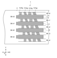
- FIG. 10 is a diagram showing the servo write head 40a and pulse signals input to the servo write head 40a.
- FIG. 11 is an enlarged view of the servo element 42 of the servo write head 40a.
- FIG. 12 shows how the servo pattern 7 is written on the magnetic tape 1 by the servo write head 40a. 10 to 12 show the surface of the servo write head 40a facing the magnetic tape 1.
- FIG. 10 is a diagram showing the servo write head 40a and pulse signals input to the servo write head 40a.
- FIG. 11 is an enlarged view of the servo element 42 of the servo write head 40a.
- FIG. 12 shows how the servo pattern 7 is written on the magnetic tape 1 by the servo write head 40a.
- 10 to 12 show the surface of the servo write head 40a facing the magnetic tape 1.
- the servo write head 40a has a shape that is long in the longitudinal direction (Y'' axis direction) and short in the width direction (X'' axis direction). 10 and 11, the longitudinal direction of the servo write head 40a is the Y''-axis direction, the width direction of the servo write head 40a is the X''-axis direction, and the vertical direction of the servo write head 40a is the Z''-axis direction.
- the longitudinal direction (conveyance direction) of the magnetic tape 1 is the X-axis direction, the width direction of the magnetic tape 1 is the Y-axis direction, and the thickness direction of the magnetic tape 1 is the Z-axis direction. Note that this also applies to FIGS.
- the longitudinal direction (Y'' axis direction) of the servo write head 40a coincides with the width direction (Y'' axis direction) of the magnetic tape 1, and the width direction (X'' axis direction) of the servo write head 40a is aligned. coincides with the longitudinal direction (X-axis direction) of the magnetic tape 1 .
- the servo write head 40 a has a facing surface 41 facing the magnetic tape 1 .
- the facing surface 41 has a shape that is long in the longitudinal direction (Y′′ axis direction) and short in the width direction (X′′ axis direction).
- the servo write head 40 a has five pairs of servo elements 42 (magnetic gaps) on the facing surface 41 .
- the five pairs of servo elements 42 are arranged at predetermined intervals (servo element pitch: SP) in the longitudinal direction (Y′′-axis direction) of the servo write head 40a.
- the interval (servo element pitch) between two pairs of adjacent servo elements 42 is, for example, 2858.8. In the magnetic tape 1, this value corresponds to the interval (servo band pitch: SP) between two servo bands s adjacent to each other in the width direction (Y-axis direction) of the magnetic tape 1. handle.
- the pair of servo elements 42 includes a first servo element 42a (“/” ) and a second servo element 42b (“ ⁇ ”) (see FIG. 11 in particular).
- the first servo element 42a (“/”) is inclined at a first angle ⁇ s1 with respect to the longitudinal direction (Y′′-axis direction) of the servo write head 40a (width direction of the magnetic tape 1: Y-axis direction).
- the second servo element 42b (“ ⁇ ”) is positioned at a first angle ⁇ s1 with respect to the longitudinal direction (Y′-axis direction) of the servo write head 40a (width direction of the magnetic tape 1: Y-axis direction). It inclines in the opposite direction at a second angle ⁇ s2.
- the reference angle Ref ⁇ of the data write head 20 is 10° and the servo azimuth angle ⁇ a is 12°
- the first angle ⁇ s1 of the first servo element 42a (“/”) is 22°
- the second angle ⁇ s2 of the second servo element 42b (“ ⁇ ”) is 2°.
- the first servo element 42a (“/”) and the second servo element 42b (“ ⁇ ”) is, for example, 38 ⁇ m at a position half the width direction component SL of the length of the servo element.
- the direction along the first angle ⁇ s1 (the direction at 22° with respect to the width direction of the magnetic tape 1) is the first servo element 42a ("/"). ) in the longitudinal direction.
- the direction along the second angle ⁇ s2 (the direction of -2° with respect to the width direction of the magnetic tape 1) is shifted to the second servo element 42b (" ⁇ " ) in the longitudinal direction.
- the longitudinal length of the first servo element 42a (“/”) is different than the longitudinal length of the second servo element 42b (" ⁇ "), which in the example shown is the first
- the longitudinal length of the servo element 42a (“/”) is longer than the longitudinal length of the second servo element 42b (“ ⁇ ”).
- the component SL (Y-axis direction) in the width direction of the magnetic tape 1 in the length in the longitudinal direction of the first servo element 42a (“/”) and the length of the second servo element 42b (“ ⁇ ”) The component SL in the width direction of the magnetic tape 1 (in the Y-axis direction) in the length in the direction is the same.
- the width direction component SL of the length of the servo element 42 is set to 96 ⁇ 3 ⁇ m, for example.
- FIG. 10 shows pulse signals input to five pairs of servo elements 42, respectively.
- FIG. 12 also shows a servo pattern 7 written in the servo band s of the magnetic tape 1 by inputting the pulse signal to the five pairs of servo elements 42 .
- the data write head 20 is arranged at an azimuth angle ⁇ with respect to the width direction of the magnetic tape 1 .
- pulse signals of the same phase are input to five pairs of servo elements 42 at the same time, and servo patterns 7 of the same phase are written at positions parallel to the width direction of the magnetic tape 1. do.
- the phases of the servo patterns 7 read at the same time by the two servo read sections 22 of the data write head 20 arranged at an angle will differ.
- the phases of the pulse signals inputted to the five pairs of servo elements 42 at the same time are varied so that the servo patterns 7 of the same phase are made non-parallel to the width direction of the magnetic tape 1. I am planning to write.
- phase difference between pulse signals input to two pairs of servo elements 42 adjacent to each other in the longitudinal direction (Y′-axis direction: width direction of the magnetic tape 1) of the servo write head 40a is SP ⁇ tan(Ref ⁇ ).
- phase differences of the input pulses of the servo elements 42 of the servo band s3, the servo band s2, the servo band s1, and the servo band s0 with respect to the input pulse of the servo element 42 of the servo band s4 are 504.08 ⁇ m in order. , 1008.17 ⁇ m, 1512.25 ⁇ m, and 2016.33 ⁇ m.
- the input pulse with the most advanced phase is input to the five pairs of servo elements 42 corresponding to the five servo bands s, in the servo band s0. is the servo element 42 of .
- the order of the phases of the input pulses is the order of the servo element 42 of the servo band s1, the servo element 42 of the servo band s2, the servo element 42 of the servo band s3, and the servo element 42 of the servo band s4.
- the servo element 42 of the servo band s0 corresponds to 504.08 ⁇ m more than the servo element 42 of the servo band s1.
- a pulse signal of the previous phase is input for the phase.
- phase difference in the width direction (Y-axis direction) of the magnetic tape 1 between the servo patterns 7 written in two servo bands s adjacent to each other in the width direction of the magnetic tape 1 is SP ⁇ tan(Ref ⁇ ).
- phase differences of the servo patterns 7 of the servo band s3, the servo band s2, the servo band s1, and the servo band s2 with respect to the servo pattern 7 of the servo band s4 are 504.08 ⁇ m, 1008.17 ⁇ m, 1512.25 ⁇ m, The phase corresponds to 2016.33 ⁇ m.
- the servo pattern 7 of the servo band s0 has the most advanced phase in the width direction (Y-axis direction) of the magnetic tape 1.
- the order of phases is the order of servo pattern 7 of servo band s1, servo pattern 7 of servo band s2, servo pattern 7 of servo band s3, and servo pattern 7 of servo band s4.
- the phase of the servo pattern 7 of the servo band s0 is 504 degrees higher than that of the servo pattern 7 of the servo band s1.
- the phase corresponding to 0.08 ⁇ m is the previous phase.
- the servo pattern 7 written in the five servo bands s is assumed to be in phase.
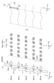
- FIG. 13 is an enlarged view of the servo write head 40b and the servo element 42 of the servo write head 40b according to the second embodiment.
- FIG. 14 is a diagram showing how the servo pattern 7 is written on the magnetic tape 1 by the servo write head 40b according to the second embodiment. 13 and 14 show the surface of the servo write head 40b facing the magnetic tape 1. FIG. 15 to 19, which will be described later, similarly show the surface of the servo write head 40 facing the magnetic tape 1. As shown in FIG.
- the servo write head 40b has a shape that is long in the longitudinal direction (Y'' axis direction) and short in the width direction (X'' axis direction).
- the servo write head 40b is arranged such that the longitudinal direction (Y′′-axis direction) of the servo write head 40b is inclined at a predetermined angle (second head azimuth angle) with respect to the width direction of the magnetic tape 1.
- the angle at which the longitudinal direction (Y′′-axis direction) of 40b is inclined with respect to the width direction (Y-axis direction) of the magnetic tape 1 is related to the reference angle Ref ⁇ of the data write head 20. It matches the angle Ref ⁇ (for example, 10°).
- the servo write head 40 b has a facing surface 41 that faces the magnetic tape 1 .
- the facing surface 41 has a shape that is long in the longitudinal direction (Y′′ axis direction) and short in the width direction (X′′ axis direction).
- the servo write head 40 b has five pairs of servo elements 42 (magnetic gaps) on the facing surface 41 .
- the five pairs of servo elements 42 are arranged at predetermined intervals (servo element pitch: SP1) in the width direction (Y-axis direction) of the magnetic tape 1 .
- the interval (servo element pitch: SP1) in the width direction (Y-axis direction) of the magnetic tape 1 between two pairs of servo elements 42 adjacent to each other is, for example, 2858.8 ⁇ 4.6 ⁇ m. This value corresponds to the interval (servo band pitch: SP1) between two servo bands s adjacent to each other in the width direction (Y-axis direction) of the magnetic tape 1 .
- Ref ⁇ is the reference angle of the data write head 20 .
- the value of SP1 is 2858.8 ⁇ m and the reference angle Ref ⁇ in the data write head 20 is 10°.
- the pair of servo elements 42 includes a first servo element 42a ("/") and a second servo element 42b (" ⁇ ") that are asymmetrical with respect to the width direction (Y-axis direction) of the magnetic tape 1. (See in particular the right side of FIG. 13).
- the first servo element 42a (“/") is inclined at a first angle ⁇ s1 with respect to the width direction (Y-axis direction) of the magnetic tape 1.
- the second servo element 42b (“ ⁇ ”) is inclined at a second angle ⁇ s2 opposite to the first angle ⁇ s1 with respect to the width direction (Y-axis direction) of the magnetic tape 1 .
- the reference angle Ref ⁇ of the data write head 20 is 10° and the servo azimuth angle ⁇ a is 12°
- the first angle ⁇ s1 of the first servo element 42a (“/”) is 22°
- the second angle ⁇ s2 of the second servo element 42b (“ ⁇ ”) is 2°.
- the interval between the first servo element 42a ("/") and the second servo element 42b (“ ⁇ ") is, for example, the width of the length of the servo element 42. It is 38 ⁇ m at the half position of the directional component SL.
- the direction along the first angle ⁇ s1 (the direction at 22° with respect to the width direction of the magnetic tape 1) is the first servo element 42a ("/"). ) in the longitudinal direction.
- the direction along the second angle ⁇ s2 (the direction of -2° with respect to the width direction of the magnetic tape 1) is shifted to the second servo element 42b (" ⁇ " ) in the longitudinal direction.
- the longitudinal length of the first servo element 42a (“/”) is different than the longitudinal length of the second servo element 42b (" ⁇ "), which in the example shown is the first
- the longitudinal length of the servo element 42a (“/”) is longer than the longitudinal length of the second servo element 42b (“ ⁇ ”).
- the width direction component (Y-axis direction) SL1 of the magnetic tape 1 in the longitudinal length of the first servo element 42a ("/") and the length of the second servo element 42b (" ⁇ ") It is the same as the width direction component (Y-axis direction) SL1 of the magnetic tape 1 in the length in the direction.
- the width direction component SL1 of the length of the servo element 42 is set to 96 ⁇ 3 ⁇ m, for example.
- FIG. 18 is an enlarged view of the right side of FIG. 13, showing an example of specific dimensions of the first servo element 42a (“/”) and the second servo element 42b (“ ⁇ ”). (XYZ coordinate system reference).
- the phase difference was set for the pulse signals respectively input to the five pairs of servo elements 42 .
- the servo write head 40b since the servo write head 40b is tilted, it is not necessary to set a phase difference with respect to the pulse signal. In other words, pulse signals corresponding to the same phase at the same time are input to the five pairs of servo elements 42 respectively.
- FIG. 14 shows servo patterns 7 written in five servo bands s by five pairs of servo elements 42, respectively.
- phase difference in the width direction of the magnetic tape 1 between the servo patterns 7 written in two servo bands s adjacent to each other in the width direction (Y-axis direction) of the magnetic tape 1 is represented by SP1 ⁇ tan(Ref ⁇ ). .
- the value of SP1 is 2858.8 ⁇ m and the reference angle Ref ⁇ in the data write head 20 is 10°.
- the phase differences of the servo patterns 7 of the servo band s3, the servo band s2, the servo band s1, and the servo patterns 7 of the servo band s1 with respect to the servo pattern 7 of the servo band s4 are 504.08 ⁇ m, 1008.17 ⁇ m, 1512 .mu.m, respectively.
- the phases correspond to 25 ⁇ m and 2016.33 ⁇ m.
- the servo pattern 7 of the servo band s0 has the most advanced phase in the width direction (Y-axis direction) of the magnetic tape 1.
- the order of phases is the order of servo pattern 7 of servo band s1, servo pattern 7 of servo band s2, servo pattern 7 of servo band s3, and servo pattern 7 of servo band s4.
- the phase of the servo pattern 7 of the servo band s0 is 504 degrees higher than that of the servo pattern 7 of the servo band s1.
- the phase corresponding to 0.08 ⁇ m is the previous phase.
- the servo pattern 7 written in the five servo bands s is assumed to be in phase.
- the configuration of the servo write head 40b based on the coordinate system (XYZ coordinate system) of the magnetic tape 1 has been described.
- the configuration of the servo write head 40b based on the coordinate system (X′′Y′′Z′′ coordinate system) of the servo write head 40b will be described.
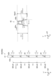
- FIG. 15 is a diagram showing the servo write head 40b with reference to the coordinate system of the servo write head 40b in the second embodiment.
- the five pairs of servo elements 42 are arranged at predetermined intervals (servo element pitch: SP2) in the longitudinal direction (Y′′-axis direction) of the servo write head 40b.
- the interval (servo element pitch: SP2) between two pairs of servo elements 42 adjacent to each other in the longitudinal direction (Y′′-axis direction) of 40b is represented by SP1 ⁇ cos ⁇ 1 (Ref ⁇ ).
- the interval (servo element pitch: SP1) between two pairs of servo elements 42 adjacent to each other is 2858.8 ⁇ m, and the reference angle Ref ⁇ of the data write head 20 is 10°.
- the interval (servo element pitch: SP2) between two pairs of servo elements 42 adjacent to each other in the longitudinal direction (Y′′-axis direction) of the servo write head 40b is 2902.9 ⁇ m.
- the axis of symmetry of the first servo element 42a (“/") and the second servo element 42b (“ ⁇ ") is the width direction (Y-axis direction) of the magnetic tape 1. and the longitudinal direction (Y′′-axis direction) of the servo write head 40b.
- the first servo element 42a (“/” ) and the second servo element 42b (“ ⁇ ") are non-parallel to the width direction (Y-axis direction) of the magnetic tape 1, while the longitudinal direction (Y''-axis direction).
- the first servo element 42a (“/”) is inclined at a servo azimuth angle ⁇ a with respect to the longitudinal direction (Y′′-axis direction) of the servo write head 40b. ) is the same as the first servo element 42a (“/”) in the opposite direction to the first servo element 42a (“/”) with respect to the longitudinal direction (Y′′-axis direction) of the servo write head 40b. It tilts at the servo azimuth angle ⁇ a.
- the direction along the servo azimuth angle ⁇ a (the direction +12° with respect to the longitudinal direction of the servo write head 40b) is the first servo element 42a ("/"). ) in the longitudinal direction.
- the direction along the servo azimuth angle ⁇ a (the direction of -12° with respect to the longitudinal direction of the servo write head 40b) is set to the second servo element 42b (" ⁇ " ) in the longitudinal direction.
- the longitudinal length of the first servo element 42a (“/”) is different than the longitudinal length of the second servo element 42b (" ⁇ "), which in the example shown is the first
- the longitudinal length of the servo element 42a (“/”) is longer than the longitudinal length of the second servo element 42b (“ ⁇ ”).
- the longitudinal component SL21 (Y′′-axis direction) of the servo write head 40b in the longitudinal length of the first servo element 42a (“/”) and the second servo element 42b (“ ⁇ ”) The longitudinal direction component SL22 (Y′′-axis direction) of the servo write head 40b in the length of the longitudinal direction is also different.
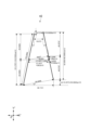
- FIG. 19 is an enlarged view of the right side of FIG. 15, showing an example of specific dimensions of the first servo element 42a (“/”) and the second servo element 42b (“ ⁇ ”). (X"Y"Z" coordinate system reference).
- the width direction component SL1 (Y-axis direction) of the magnetic tape 1 in the length of the servo element 42 is 96 ⁇ m
- the reference angle Ref ⁇ of the data write head 20 is 10°
- the servo azimuth angle ⁇ a is 12°.
- FIG. 12 shows how the two servo read sections 22 of the data write head 20 are reading the servo pattern 7 written by the servo write head 40a according to the first embodiment.
- the servo write head 40a As described above, in the servo write head 40a according to the first embodiment, the servo write head 40a is arranged without being inclined with respect to the width direction of the magnetic tape 1, and the phase of the pulse signal input to the servo element 42 is adjusted. A method of writing the servo pattern 7 by doing so is used.
- the magnetic tape 1 may slightly move in the width direction (in the Y-axis direction).
- the servo element 42 of the servo band s0 writes a servo pattern 7 of a certain phase ph1 at a certain time t1 to the servo band s0.
- the servo element 42 of the servo band s1 writes the servo pattern 7 of the phase ph1 to the servo band s1 at the subsequent time t2 (the time when the magnetic tape 1 is conveyed 504.08 ⁇ m in the conveying direction). .
- the magnetic tape 1 slightly moves in the width direction between time t1 and time t2.
- the interval (direction of the reference angle Ref ⁇ (10°)) between the position of the servo pattern 7 of phase ph1 in the servo band s0 and the position of the servo pattern 7 of phase ph1 in the servo band s1 is a predetermined value. (the interval between the two servo read portions 22: the direction of the reference angle Ref ⁇ (10°)).
- FIG. 14 shows how the two servo read sections 22 of the data write head 20 are reading the servo pattern 7 written by the servo write head 40b according to the second embodiment.
- the servo write head 40b is inclined with respect to the width direction of the magnetic tape 1, and the phases of the pulse signals input to the servo elements 42 are set to be the same to form the servo pattern 7. A writing method is used.
- the servo elements 42 of the servo band s0 and the servo elements 42 of the servo band s1 perform servo operations of the same phase ph1 at the same time t1 for the servo bands s0 and s1. Assume that pattern 7 is written.
- the interval between the position of the servo pattern 7 of phase ph1 in the servo band s0 and the position of the servo pattern 7 of phase ph1 in the servo band s1 (in the direction of the reference angle Ref ⁇ (10°)) is is the same as the interval between the position of the servo pattern 7 of phase ph2 at s1 and the position of the servo pattern 7 of phase ph2 at servo band s1.
- These intervals are the same as the predetermined value (the interval between the two servo read sections 22: the direction of the reference angle Ref ⁇ (10°)) and are constant.
- the interval (in the direction of the reference angle Ref ⁇ ) between the servo patterns 7 of the same phase in the mutually adjacent servo bands s is adjusted to can be made constant.
- the data write head 20 can accurately servo trace the servo pattern 7 .
- the second embodiment is more advantageous than the first embodiment from the viewpoint of fine movement in the width direction of the magnetic tape 1 when writing the servo pattern 7 .
- this does not mean that the method according to the first embodiment cannot be adopted, and the first embodiment is also included as an example of the present technology.
- the fine movement in the width direction of the magnetic tape 1 during writing of the servo pattern 7 may be at a negligible level, or the fine movement in the width direction of the magnetic tape 1 at the time of writing the servo pattern 7 may be suppressed to a negligible level. If it is possible, the method according to the first embodiment may be adopted.
- the facing surface 41 of the servo write head 40 may be subjected to low-friction processing to intentionally draw air between itself and the magnetic tape 1 to reduce frictional resistance.
- FIG. 16 is a diagram showing how the facing surface 41 of the servo write head 40 is subjected to low-friction processing.
- the left side of FIG. 16 shows how the facing surface 41 of the servo write head 40a according to the first embodiment is subjected to low-friction processing.
- the right side of FIG. 16 shows a state where the facing surface 41 of the servo write head 40b according to the second embodiment is subjected to low-friction processing.
- the facing surface 41 of the servo write head 40a is positioned so that the servo element 42 extends in the longitudinal direction of the servo write head 40 (Y-axis direction: width direction of the magnetic tape 1). It has a first area 43 corresponding to the area where the servo element 42 is provided and a second area 44 corresponding to the area where the servo element 42 is not provided.
- a plurality of grooves along the width direction of the servo write head 40a are formed in the longitudinal direction of the servo write head 40a (the Y-axis direction: the longitudinal direction of the magnetic tape 1). width direction).
- the facing surface 41 of the servo write head 40b is arranged in the longitudinal direction of the servo write head 40 (in the direction of the reference angle Ref ⁇ with respect to the width direction of the magnetic tape 1): It has a first region 43 corresponding to the region provided with the servo element 42 and a second region 44 corresponding to the region not provided with the servo element 42 .
- a plurality of grooves are formed along the direction of the reference angle Ref ⁇ (X-axis direction: longitudinal direction of the magnetic tape 1) with respect to the width direction (X′′-axis direction) of the servo write head 40b. They are aligned along the direction of the reference angle Ref ⁇ (Y-axis direction: width direction of the magnetic tape 1) with respect to the longitudinal direction (Y′′-axis direction) of the head 40 .
- a plurality of grooves extending in the direction parallel to the width direction of the servo write head 40a extend in the direction parallel to the longitudinal direction of the servo write head 40a. aligned along.
- second embodiment on the right side of FIG. Aligned along non-parallel directions.
- the opposing surface 41 is subjected to low-friction processing, so that the vibration of the magnetic tape 1 due to friction can be suppressed. , the servo pattern 7 can be written accurately.
- a plurality of grooves along the direction of the reference angle Ref ⁇ (X-axis direction: longitudinal direction of the magnetic tape 1) with respect to the width direction (X′′-axis direction) of the servo write head 40b They are aligned along the direction of the reference angle Ref ⁇ (Y-axis direction: width direction of the magnetic tape 1) with respect to the longitudinal direction (Y′′-axis direction) of the servo write head 40 .
- the friction between the servo write head 40 and the magnetic tape 1 can be appropriately reduced.
- the servo write head 40 creates the first servo patterns 7a ("/") asymmetrical with respect to the width direction of the magnetic tape 1 and A second servo pattern 7b (" ⁇ ") can be written respectively.
- the data write head 20 when the data write head 20 is arranged to be tilted with respect to the width direction of the magnetic tape 1, the data write head 20 can read the servo pattern 7 accurately.
- FIG. 17 is a diagram showing how the servo pattern 7 is read by the servo read section 22 of the data write head 20 in the first comparative example, the second comparative example, and the present embodiment.
- the first servo pattern 7a (“/”) and the second servo pattern 7b (“ ⁇ ”) are the width of the magnetic tape 1. It is symmetrical with respect to the direction. Also, the longitudinal direction of the data write head 20 is parallel to the width direction of the magnetic tape 1 .
- the azimuth loss of the servo pattern 7 with respect to the servo read portion 22 of the data write head 20 is the same for every 7 groups of servo patterns. Therefore, when the servo pattern 7 is read by the servo read section 22 of the servo write head 40, the output of the servo signal is the same for each servo burst corresponding to the servo pattern 7 group.
- the first servo pattern 7a (“/”) and the second servo pattern 7b (“ ⁇ ”) correspond to the width of the magnetic tape 1. It is symmetrical with respect to the direction. On the other hand, the longitudinal direction of the data write head 20 is inclined with respect to the width direction of the magnetic tape 1 .
- the azimuth loss of the servo pattern 7 with respect to the servo read portion 22 of the data write head 20 differs for each group of servo patterns. Therefore, when the servo pattern 7 is read by the servo read section 22 of the servo write head 40, in the servo signal, the output of the servo burst corresponding to the servo pattern 7 group with little azimuth loss is large, while the azimuth loss is large. The output of the servo burst corresponding to the 7th group of servo patterns with a large value is small. Therefore, an error may occur in the tracking reference position.
- the first servo pattern 7a ("/") and the second servo pattern 7b (“ ⁇ ") are arranged in the width direction of the magnetic tape 1. is asymmetric with respect to Also, the longitudinal direction of the data write head 20 is not parallel to the width direction of the magnetic tape 1 .
- the azimuth loss of the servo pattern 7 with respect to the servo read portion 22 of the data write head 20 is the same for every 7 groups of servo patterns. Therefore, when the servo pattern 7 is read by the servo read section 22 of the servo write head 40, the output of the servo signal is the same for each servo burst corresponding to the servo pattern 7 group.
- the first servo pattern 7a (“/") and the second servo pattern 7b (“ ⁇ ") are asymmetrical with respect to the width direction of the magnetic tape 1, so that the data When the write head 20 is arranged tilted with respect to the width direction of the magnetic tape 1, the data write head 20 can read the servo pattern 7 accurately.
- the longitudinal direction of the data write head 20 in the data recording/reproducing device 100 is arranged at an azimuth angle ⁇ with respect to the width direction of the magnetic tape 1, and the azimuth angle ⁇ is adjusted. As a result, variations in the width of the magnetic tape 1 can be accommodated.
- the azimuth angle ⁇ of the data write head 20 is adjusted within the range of the reference angle Ref ⁇ x°.
- the correction amount can be increased (for example, 10 ⁇ m or more).
- the first servo element 42a (“/") and the second servo element 42b (“ ⁇ ") are asymmetrical with respect to the width direction of the magnetic tape 1. are provided in the servo write head 40 so as to be as follows.
- the servo pattern 7 asymmetric with respect to the width direction of the magnetic tape 1 can be appropriately written by the first servo element 42a ("/") and the second servo element 42b (" ⁇ ").
- the first servo element 42a (“/") is inclined at the first angle ⁇ s1 with respect to the width direction of the magnetic tape 1
- the second servo element 42b (“ ⁇ ") is , with respect to the width direction of the magnetic tape 1, at a second angle .theta.s2 different from the first angle .theta.s1, opposite to the first angle .theta.s1.
- the first angle ⁇ s1 and the second angle ⁇ s2 are related to the reference angle Ref ⁇ of the data write head 20 .
- the first servo element 42a ("/") and the second servo element 42b (" ⁇ ") appropriately write the asymmetric servo pattern 7 that can be accurately read by the data write head 20. can be done.
- the length in the longitudinal direction of the first servo element 42a (“/”) is different from the length in the longitudinal direction of the first servo element 42a ("/").
- the component in the width direction of the magnetic tape 1 in the length of the second servo element 42a (“/") is the same as the component in the width direction of the magnetic tape 1 in the length of the second servo element 42b (“ ⁇ "). be.
- the first servo pattern 7a (“/”) and the second servo pattern 7b (“ ⁇ ”) written by the first servo element 42a (“/”) and the second servo element 42b (“ ⁇ ”) are written. ”), the length of the magnetic tape 1 in the width direction can be made uniform.
- the longitudinal direction of the servo write head 40 may be arranged so as to be inclined at a predetermined angle with respect to the width direction of the magnetic tape 1 (see the second embodiment). It is possible to appropriately cope with the slight movement in the width direction of the magnetic tape 1 when the pattern 7 is written.
- the angle at which the longitudinal direction of the servo write head 40 is inclined with respect to the width direction of the magnetic tape 1 may be related to the reference angle Ref ⁇ of the data write head 20, and this angle may match the reference angle Ref ⁇ of the data write head 20 .
- an asymmetric servo pattern 7 that can be accurately read by the tilted data write head 20 can be appropriately written.
- the phase difference in the width direction of the magnetic tape 1 between the servo patterns 7 in the mutually adjacent servo bands s is related to the reference angle Ref ⁇ of the servo write head 40. It is represented by SP ⁇ tan(Ref ⁇ ). As a result, the servo pattern 7 can be accurately read by the tilted data write head 20 .
- FIG. 20 is a diagram showing a first example of a method for confirming whether or not the magnetic tape 1 is the magnetic tape 1 used in the data write head tilt type data recording/reproducing apparatus 100.
- the angle (first angle ⁇ s1) at which the first servo pattern 7a (“/”) is inclined with respect to the width direction (Y-axis direction) of the magnetic tape 1 and the second servo pattern
- the following confirmation is performed based on the angle (second angle ⁇ s2) at which 7b (" ⁇ ") is inclined with respect to the width direction of the magnetic tape.
- the 20 shows the magnetic tape 1 viewed from the upper side (magnetic layer side) (therefore, the first servo pattern 7a (“/”), the second servo pattern 7b (“ ⁇ ”) ), the signs of "/” and " ⁇ " are opposite to what they appear to be).
- the magnetic layer 4 of the magnetic tape 1 is developed by applying a developer such as a ferricolloid developer (for example, SigmarQ Q (registered trademark) manufactured by Sigma High Chemical Co., Ltd.). conduct. After that, the shape of the servo pattern 7 is confirmed by observing the magnetic layer 4 of the developed magnetic tape 1 with an optical microscope.
- a developer such as a ferricolloid developer (for example, SigmarQ Q (registered trademark) manufactured by Sigma High Chemical Co., Ltd.).
- the upper and lower ends of the first servo pattern 7a (“/") and the upper and lower ends of the second servo pattern 7b (“ ⁇ ") are measured as measurement points. Then, the distance a (corresponding to the servo band width) between the upper end and the lower end of the servo pattern 7 in the width direction (Y-axis direction) of the magnetic tape 1 is measured.
- the distance b between the upper end and the lower end of the first servo pattern 7a (“/" is measured. Also, in the longitudinal direction (X-axis direction) of the magnetic tape 1, the distance c between the upper end and the lower end of the second servo pattern 7b (“ ⁇ ") is measured.
- the angle (first angle ⁇ s1) at which the first servo pattern 7a (“/”) is inclined with respect to the width direction (Y-axis direction) of the magnetic tape 1 is tan ⁇ 1 (b/a) required by
- the angle (second angle ⁇ s2) at which the second servo pattern 7b (“ ⁇ ”) is inclined with respect to the width direction (Y-axis direction) of the magnetic tape 1 is given by tan ⁇ 1 (c/a). Desired.
- the angle obtained at this time corresponds to the angle at which the axes of symmetry of the first servo pattern 7a and the second servo pattern 7b are inclined with respect to the width direction of the magnetic tape 1 (Y-axis direction).
- the azimuth loss of the servo pattern 7 with respect to the servo read portion 22 of the data write head 20 is the same for every 7 groups of servo patterns.
- the output of the servo signal is the same for each servo burst corresponding to the group of servo patterns 7.
- the magnetic tape 1 can be regarded as a magnetic tape 1 used in a data recording/reproducing apparatus 100 in which the data write head 20 is arranged obliquely with respect to the width direction (Y-axis direction) of the magnetic tape 1. .
- FIG. 21 is a diagram showing a second example of a method for confirming whether or not the magnetic tape 1 is the magnetic tape 1 used in the data write head tilt type data recording/reproducing apparatus 100.
- the verification is based on the phase difference in the servo patterns 7 in mutually adjacent servo bands.
- a data recording/reproducing device is used.
- the data write head 20 is arranged parallel to the width direction (Y-axis direction) of the magnetic tape 1 .
- the two servo read sections 22 of the data write head 20 respectively read the servo patterns 7 in the servo bands adjacent to each other, and reproduce the servo signals.
- phase of the servo signal reproduced by the lower servo read section 22 precedes the phase of the servo signal reproduced by the upper servo read section 22, resulting in a phase difference.
- the difference in time when the same LPOS (Longitudinal Position) information is read between the servo signal reproduced by the lower servo read section 22 and the servo signal reproduced by the upper servo read section 22 is obtained. be done. Then, this time difference is converted into a distance, and a phase difference d in the longitudinal direction of the magnetic tape is obtained (for example, 0.505 ⁇ m).
- phase difference d for example, 0.505 ⁇ m
- servo band pitch SP known
- tan ⁇ 1 d/SP
- the angle obtained at this time is defined by a straight line connecting the positions where the information of the same phase is written in the servo pattern 7 of one servo band and the servo pattern 7 of the other servo band and formed with respect to the width direction of the magnetic tape. corresponds to the angle.
- this magnetic tape 1 is assumed to be a magnetic tape 1 used in a data recording/reproducing apparatus 100 in which the data write head 20 is arranged obliquely with respect to the width direction (Y-axis direction) of the magnetic tape 1. can be regarded.
- the magnetic tape 1 has a long tape shape, and is run in the longitudinal direction when data and servo patterns 7 are recorded/reproduced.
- the surface of the magnetic layer 4 is the surface on which the data write head 20 and the servo write head 40 travel.
- the magnetic tape 1 is preferably used in a recording/reproducing apparatus having a ring head as a recording head.
- the magnetic tape 1 is preferably used in a recording/reproducing apparatus capable of recording data with a data track width of 1200 nm or less or 1000 nm or less.
- the substrate 2 is a non-magnetic support that supports the underlayer 3 and the magnetic layer 4 .
- the base material 2 has a long film shape.
- the upper limit of the average thickness of the substrate 2 is preferably 4.4 ⁇ m or less, more preferably 4.2 ⁇ m or less, still more preferably 4.0 ⁇ m or less, and most preferably 3.6 ⁇ m or less.
- the recording capacity that can be recorded in one data cartridge 10 can be made higher than that of a general magnetic tape 1 .
- the lower limit of the average thickness of the substrate 2 is preferably 3 ⁇ m or more, more preferably 3.2 ⁇ m or more. When the lower limit of the average thickness of the base material 2 is 3 ⁇ m or more, a decrease in the strength of the base material 2 can be suppressed.
- the average thickness of the base material 2 is obtained as follows. First, a magnetic tape 1 having a width of 1/2 inch is prepared and cut into a length of 250 mm to prepare a sample. Subsequently, the layers of the sample other than the substrate 2 (that is, the underlayer 3, the magnetic layer 4 and the back layer 5) are removed with a solvent such as MEK (methyl ethyl ketone) or dilute hydrochloric acid. Next, using a Mitutoyo laser hologram (LGH-110C) as a measuring device, the thickness of the sample (substrate 2) is measured at five or more points, and the measured values are simply averaged (arithmetic average ) to calculate the average thickness of the substrate 2 . It is assumed that the measurement position is randomly selected from the sample.
- a Mitutoyo laser hologram LGH-110C
- the base material 2 preferably contains polyester.
- the longitudinal Young's modulus of the substrate 2 is, for example, 2.5 GPa or more and 10 GPa or less, preferably 2.5 GPa or more and 7.8 GPa or less, more preferably 3.0 GPa or more and 7.0 GPa or less.
- Polyesters are, for example, polyethylene terephthalate (PET), polyethylene naphthalate (PEN), polybutylene terephthalate (PBT), polybutylene naphthalate (PBN), polycyclohexylene dimethylene terephthalate (PCT), polyethylene-p-oxybenzoate ( PEB) and at least one of polyethylene bisphenoxycarboxylate.
- PET polyethylene terephthalate
- PEN polyethylene naphthalate
- PBT polybutylene terephthalate
- PBN polybutylene naphthalate
- PCT polycyclohexylene dimethylene terephthalate
- PEB polyethylene-p-oxybenzoate
- at least one of the terminal and the side chain of the polyester may be modified.
- polyester in the base material 2 can be confirmed, for example, as follows. First, similarly to the method for measuring the average thickness of the base material 2, the magnetic tape 1 is prepared, cut into a length of 250 mm to prepare a sample, and then the layers other than the base material 2 are removed from the sample. Next, an IR spectrum of the sample (substrate 2) is acquired by infrared absorption spectrometry (IR). Based on this IR spectrum, it can be confirmed that the substrate 2 contains polyester.
- IR infrared absorption spectrometry
- the base material 2 may be, other than polyester, for example, polyamide, polyetheretherketone, polyimide and polyamideimide, polyetheretherketone (PEEK), polyolefins, cellulose derivatives, vinyl resins, and other polymer resins.
- the polyamide may be an aromatic polyamide (aramid).
- the polyimide may be an aromatic polyimide.
- the polyamideimide may be an aromatic polyamideimide.
- the base material 2 may contain at least one of polyamide, polyetheretherketone, polyimide, polyamideimide, and polyetheretherketone (PEEK), or may include polyamide, polyimide, polyamideimide, polyolefins, and cellulose derivatives.
- a resin such as a vinyl resin may be used as a main component.
- the base material 2 when the base material 2 contains a polymer resin other than polyester, the base material 2 preferably contains polyester as the main component.
- the main component means the component with the highest content (mass ratio) among the polymer resins contained in the substrate 2 .
- the polyester and the polymer resin other than polyester may be mixed or copolymerized.
- the base material 2 may be biaxially stretched in the longitudinal direction and the width direction.
- the polymer resin contained in the base material 2 is preferably oriented obliquely with respect to the width direction of the base material 2 .
- the magnetic layer 4 is a recording layer for recording signals by magnetization patterns.
- the magnetic layer 4 may be a perpendicular recording type recording layer or a longitudinal recording type recording layer.
- the magnetic layer 4 contains, for example, magnetic powder, binder and lubricant.
- the magnetic layer 4 may further contain at least one additive selected from antistatic agents, abrasives, hardening agents, rust preventives, non-magnetic reinforcing particles, and the like, if necessary.
- the magnetic layer 4 is not limited to being composed of a coated film of a magnetic material, and may be composed of a sputtered film or vapor-deposited film of a magnetic material.
- the arithmetic mean roughness Ra of the surface of the magnetic layer 4 is 2.0 nm or less, preferably 1.8 nm or less, more preferably 1.6 nm or less. When the arithmetic mean roughness Ra is 2.0 nm or less, it is possible to suppress the decrease in output due to the spacing loss, so excellent electromagnetic conversion characteristics can be obtained.
- the lower limit of the arithmetic mean roughness Ra of the surface of the magnetic layer 4 is preferably 1.0 nm or more, more preferably 1.2 nm or more. When the lower limit of the arithmetic mean roughness Ra of the surface of the magnetic layer 4 is 1.0 nm or more, it is possible to suppress deterioration in running performance due to an increase in friction.
- the arithmetic mean roughness Ra is obtained as follows. First, the surface of the magnetic layer 4 is observed with an AFM (Atomic Force Microscope) to obtain an AFM image of 40 ⁇ m ⁇ 40 ⁇ m.
- the AFM is Nano Scope IIIa D3100 manufactured by Digital Instruments, the cantilever is made of silicon single crystal (Note 1), and the tapping frequency is tuned at 200 to 400 Hz.
- the average height (average surface) Zave ( (Z (1) + Z (2) + ... + Z ( 262, 144))/262, 144).
- the upper limit of the average thickness t m of the magnetic layer 4 is 80 nm or less, preferably 70 nm or less, more preferably 50 nm or less. If the upper limit of the average thickness t m of the magnetic layer 4 is 80 nm or less, the influence of the demagnetizing field can be reduced when a ring-type head is used as the recording head, so that even better electromagnetic conversion characteristics can be obtained. .
- the lower limit of the average thickness t m of the magnetic layer 4 is preferably 35 nm or more. If the lower limit of the average thickness t m of the magnetic layer 4 is 35 nm or more, output can be ensured when an MR head is used as the reproducing head, so that even better electromagnetic conversion characteristics can be obtained.
- the average thickness t m of the magnetic layer 4 is obtained as follows. First, the magnetic tape 1 accommodated in the cartridge 10 is unwound, and three samples are prepared by cutting the magnetic tape 1 at three positions of 10 m, 30 m, and 50 m from one end on the outermost circumference side. Subsequently, each sample (the magnetic tape 1 to be measured) is processed by the FIB method or the like to be thinned. When the FIB method is used, a carbon layer and a tungsten layer are formed as protective films as a pretreatment for observing a cross-sectional TEM image, which will be described later.
- the carbon layer is formed on the magnetic layer 4 side surface and the back layer 5 side surface of the magnetic tape 1 by vapor deposition, and the tungsten layer is further formed on the magnetic layer 4 side surface by vapor deposition or sputtering.
- the thinning is performed along the longitudinal direction (longitudinal direction) of the magnetic tape 1 . That is, by the thinning, a cross section parallel to both the longitudinal direction and the thickness direction of the magnetic tape 1 is formed.
- TEM transmission electron microscope
- the thickness of the magnetic layer 4 is measured at 10 or more points on each sliced sample.
- the ten measurement positions of each thinned sample are different positions in the longitudinal direction of the magnetic tape 1. randomly selected from.
- the average value obtained by simply averaging (arithmetic mean) the measured values of the obtained thinned samples (the thickness of the magnetic layer 4 at a total of 30 points) is defined as the average thickness t m [nm] of the magnetic layer 4. do.
- Magnetic powder includes a plurality of magnetic particles.
- the magnetic particles are, for example, particles containing hexagonal ferrite (hereinafter referred to as “hexagonal ferrite particles”), particles containing epsilon-type iron oxide ( ⁇ iron oxide) (hereinafter referred to as “ ⁇ iron oxide particles”), or Co-containing particles. It is a particle containing spinel ferrite (hereinafter referred to as “cobalt ferrite particle”).
- the magnetic powder preferably has crystal magnetic anisotropy and uniaxial anisotropy.
- the hexagonal ferrite particles have, for example, a plate shape such as a hexagonal plate shape or a columnar shape such as a hexagonal columnar shape (where the thickness or height is smaller than the major axis of the plate surface or bottom surface).
- the hexagonal slope shape includes a substantially hexagonal slope shape.
- the hexagonal ferrite preferably contains at least one of Ba, Sr, Pb and Ca, more preferably at least one of Ba and Sr.
- the hexagonal ferrite may in particular be, for example, barium ferrite or strontium ferrite. Barium ferrite may further contain at least one of Sr, Pb and Ca in addition to Ba.
- the strontium ferrite may further contain at least one of Ba, Pb and Ca in addition to Sr.
- hexagonal ferrite has an average composition represented by the general formula MFe 12 O 19 .
- M is, for example, at least one metal selected from Ba, Sr, Pb and Ca, preferably at least one metal selected from Ba and Sr.
- M may be a combination of Ba and one or more metals selected from the group consisting of Sr, Pb and Ca.
- M may be a combination of Sr and one or more metals selected from the group consisting of Ba, Pb and Ca.
- Part of Fe in the above general formula may be substituted with another metal element.
- the average particle size of the magnetic powder is preferably 13 nm or more and 22 nm or less, more preferably 13 nm or more and 19 nm or less, even more preferably 13 nm or more and 18 nm or less, and particularly preferably 14 nm or more and 17 nm. Below, it is most preferably 14 nm or more and 16 nm or less.
- the average particle size of the magnetic powder is 22 nm or less, even better electromagnetic conversion characteristics (for example, SNR) can be obtained in the high recording density magnetic tape 1 .
- the average particle size of the magnetic powder is 13 nm or more, the dispersibility of the magnetic powder is further improved, and even better electromagnetic conversion characteristics (for example, SNR) can be obtained.
- the average aspect ratio of the magnetic powder is preferably 1.0 or more and 3.0 or less, more preferably 1.5 or more and 2.8 or less, and even more preferably 1.8. 2.7 or less. If the average aspect ratio of the magnetic powder is within the range of 1.0 or more and 3.0 or less, the aggregation of the magnetic powder can be suppressed. In addition, when the magnetic powder is vertically oriented in the process of forming the magnetic layer 4, the resistance applied to the magnetic powder can be suppressed. Therefore, the perpendicular orientation of the magnetic powder can be improved.
- the average particle size and average aspect ratio of the magnetic powder are obtained as follows.
- the magnetic tape 1 to be measured is processed by the FIB method or the like to be thinned.
- a carbon layer and a tungsten layer are formed as protective films as a pretreatment for observing a cross-sectional TEM image, which will be described later.
- the carbon layer is formed on the magnetic layer 4 side surface and the back layer 5 side surface of the magnetic tape 1 by vapor deposition, and the tungsten layer is further formed on the magnetic layer 4 side surface by vapor deposition or sputtering. be.
- the thinning is performed along the longitudinal direction (longitudinal direction) of the magnetic tape 1 . That is, by the thinning, a cross section parallel to both the longitudinal direction and the thickness direction of the magnetic tape 1 is formed.
- the particle size of the hexagonal ferrite (hereinafter referred to as "particle size") means that the shape of the particles observed in the above TEM photograph is plate-like or columnar (however, the thickness or height is is smaller than the major axis of the plate surface or bottom), the major axis of the plate surface or bottom is taken as the value of the plate diameter DB.
- the thickness or height of the particles observed in the above TEM photograph is taken as the plate thickness DA value.
- the plate thickness DA When the grain thickness or height is not constant within one grain, the thickness or height of the largest grain is defined as the plate thickness DA.
- 50 particles to be extracted from the TEM photograph taken are selected based on the following criteria. Particles partly protruding outside the field of view of the TEM photograph are not measured, but particles with clear contours and present in isolation are measured. If the particles overlap each other and the boundary between them is clear and the shape of the entire particle can be determined, each particle is measured as a single particle, but the boundary is not clear and the entire shape of the particle cannot be determined. Particles that do not have a shape are not measured as the shape of the particles cannot be determined.
- the plate thickness DA of each of the 50 selected particles is measured.
- the average plate thickness DA ave is obtained by simply averaging (arithmetic mean) the plate thicknesses DA thus obtained.
- the average thickness DA ave is the average grain thickness.
- the plate diameter DB of each magnetic powder is measured.
- 50 particles whose tabular diameter DB of the particles can be clearly confirmed are selected from the photographed TEM photographs.
- the plate diameter DB of each of the 50 selected particles is measured.
- a simple average (arithmetic mean) of the plate diameters DB obtained in this way is obtained to obtain an average plate diameter DB ave .
- the average platelet diameter DB ave is the average particle size.
- the average aspect ratio (DB ave /DA ave ) of the particles is obtained from the average plate thickness DA ave and the average plate diameter DB ave .
- the average particle volume of the magnetic powder is preferably 500 nm 3 or more and 2500 nm 3 or less, more preferably 500 nm 3 or more and 1600 nm 3 or less, still more preferably 500 nm 3 or more and 1500 nm 3 or less, especially It is preferably 600 nm 3 or more and 1200 nm 3 or less, and most preferably 600 nm 3 or more and 1000 nm 3 or less.
- the average particle volume of the magnetic powder is 2500 nm 3 or less, the same effects as when the average particle size of the magnetic powder is 22 nm or less can be obtained.
- the average particle volume of the magnetic powder is 500 nm 3 or more, the same effect as when the average particle size of the magnetic powder is 13 nm or more can be obtained.
- the average particle volume of magnetic powder is determined as follows. First, the average major axis length DA ave and the average tabular diameter DB ave are determined as described above for the method of calculating the average particle size of the magnetic powder. Next, the average volume V of the magnetic powder is obtained by the following formula.
- ⁇ iron oxide particles are hard magnetic particles capable of obtaining a high coercive force even when they are fine particles.
- the ⁇ -iron oxide particles have a spherical shape or have a cubic shape.
- the spherical shape shall include substantially spherical shape.
- the cubic shape includes a substantially cubic shape. Since the ⁇ -iron oxide particles have the above-described shape, when the ⁇ -iron oxide particles are used as the magnetic particles, compared to the case where the hexagonal barium ferrite particles are used as the magnetic particles, the magnetic tape 1 It is possible to reduce the contact area between the particles in the thickness direction and suppress the aggregation of the particles. Therefore, it is possible to improve the dispersibility of the magnetic powder and obtain even better electromagnetic conversion characteristics (for example, SNR).
- SNR electromagnetic conversion characteristics
- ⁇ -iron oxide particles have a composite particle structure such as a core-shell structure, a Janus structure, or a surface-bonded structure.
- a portion of the composite structure includes ⁇ -iron oxide.
- the ⁇ -iron oxide preferably has an ⁇ -Fe 2 O 3 crystal as a main phase, more preferably a single-phase ⁇ -Fe 2 O 3 .
- the ⁇ -iron oxide part and the other part are exchange-coupled and have magnetic properties such as It preferably behaves like a single particle.
- the other part is preferably the soft magnetic layer 4, and includes, for example, a soft magnetic material such as ⁇ -Fe, Ni-Fe alloy or Fe-Si-Al alloy.
- ⁇ -Fe may be obtained by reducing ⁇ -iron oxide contained in the core. Alternatively, it may have higher ⁇ s and lower Hc than ⁇ -iron oxide, even if it is not soft magnetic.
- the ⁇ -iron oxide particles may contain an additive instead of the above structure, or may have the above structure and contain an additive. In this case, part of the Fe in the ⁇ -iron oxide particles is replaced with the additive.
- the coercive force Hc of the ⁇ -iron oxide particles as a whole can also be adjusted to a coercive force Hc suitable for recording, so that the ease of recording can be improved.
- the additive is a metal element other than iron, preferably a trivalent metal element, more preferably at least one of Al, Ga and In, still more preferably at least one of Al and Ga.
- the ⁇ -iron oxide containing additives is ⁇ -Fe 2-x M x O 3 crystals.
- the additive is a metal element other than iron, more preferably Al (aluminum), Ga (gallium), In (indium), Co (cobalt), Mn (manganese), Zr (zirconium), Hf (hafnium), Cs ( cesium) and at least one of Ti (titanium), Sm (samarium), Nd (neodymium), Pr (praseodymium) and Tb (terbium).
- the average particle size of the magnetic powder is preferably 10 nm or more and 20 nm or less, more preferably 10 nm or more and 18 nm or less, even more preferably 10 nm or more and 16 nm or less, and particularly preferably 10 nm or more and 15 nm or less. , most preferably 10 nm or more and 14 nm or less.
- a region having a size of 1/2 of the recording wavelength is the actual magnetized region. Therefore, by setting the average particle size of the magnetic powder to half or less of the shortest recording wavelength, even better electromagnetic conversion characteristics (for example, SNR) can be obtained.
- the magnetic tape 1 having a high recording density (for example, the magnetic tape 1 configured to record a signal at the shortest recording wavelength of 40 nm or less) exhibits even better electromagnetic conversion.
- a characteristic eg, SNR
- the average particle size of the magnetic powder is 10 nm or more, the dispersibility of the magnetic powder is further improved, and even better electromagnetic conversion characteristics (for example, SNR) can be obtained.
- the average aspect ratio of the magnetic powder is preferably 1.0 or more and 3.0 or less, more preferably 1.0 or more and 2.5 or less, and even more preferably 1.0 or more. 2.1 or less, particularly preferably 1.0 or more and 1.8 or less. If the average aspect ratio of the magnetic powder is within the range of 1.0 or more and 3.0 or less, the aggregation of the magnetic powder can be suppressed. In addition, when the magnetic powder is vertically oriented in the process of forming the magnetic layer 4, the resistance applied to the magnetic powder can be suppressed. Therefore, the perpendicular orientation of the magnetic powder can be improved.
- the average particle size and average aspect ratio of the magnetic powder are obtained as follows.
- the magnetic tape 1 to be measured is processed by the FIB (Focused Ion Beam) method or the like to be thinned.
- FIB Flucused Ion Beam
- a carbon layer and a tungsten layer are formed as protective layers as a pretreatment for observing a cross-sectional TEM image, which will be described later.
- the carbon layer is formed on the magnetic layer 4 side surface and the back layer 5 side surface of the magnetic tape 1 by vapor deposition, and the tungsten layer is further formed on the magnetic layer 4 side surface by vapor deposition or sputtering. be.
- Thinning is performed along the longitudinal direction (longitudinal direction) of the magnetic tape 1 . That is, by the thinning, a cross section parallel to both the longitudinal direction and the thickness direction of the magnetic tape 1 is formed.
- the above cross section of the obtained thin sample was observed at an acceleration voltage of 200 kV and a total magnification of 500,000 times. 4 Observe the cross section so that the whole is included, and take a TEM photograph. Next, 50 particles whose shape can be clearly confirmed are selected from the TEM photograph taken, and the major axis length DL and the minor axis length DS of each particle are measured.
- the major axis length DL means the maximum distance (so-called maximum Feret diameter) between two parallel lines drawn from all angles so as to touch the outline of each particle.
- the minor axis length DS means the maximum particle length in the direction perpendicular to the major axis (DL) of the particle.
- the average major axis length DL ave is obtained by simply averaging (arithmetic mean) the major axis lengths DL of the measured 50 particles.
- the average major axis length DL ave obtained in this manner is taken as the average particle size of the magnetic powder.
- the short axis length DS of the measured 50 particles is simply averaged (arithmetic mean) to obtain the average short axis length DS ave .
- the average aspect ratio (DL ave /DS ave ) of the particles is obtained from the average long axis length DL ave and the average short axis length DS ave .
- the average particle volume of the magnetic powder is preferably 500 nm 3 or more and 4000 nm 3 or less, more preferably 500 nm 3 or more and 3000 nm 3 or less, even more preferably 500 nm 3 or more and 2000 nm 3 or less, especially It is preferably 600 nm 3 or more and 1600 nm 3 or less, and most preferably 600 nm 3 or more and 1300 nm 3 or less.
- the noise of the magnetic tape 1 is inversely proportional to the square root of the number of particles (that is, proportional to the square root of the particle volume). can.
- the average particle volume of the magnetic powder is 4000 nm 3 or less, it is possible to obtain even better electromagnetic conversion characteristics (for example, SNR) as in the case where the average particle size of the magnetic powder is 20 nm or less.
- the average particle volume of the magnetic powder is 500 nm 3 or more, the same effect as when the average particle size of the magnetic powder is 10 nm or more can be obtained.
- the average volume of the magnetic powder is obtained as follows.
- the magnetic tape 1 is processed by FIB (Focused Ion Beam) method or the like to be thinned.
- FIB Flucused Ion Beam
- a carbon film and a tungsten thin film are formed as protective films as a pretreatment for observing a cross-sectional TEM image, which will be described later.
- the carbon film is formed on the magnetic layer 4 side surface and the back layer 5 side surface of the magnetic tape 1 by vapor deposition, and the tungsten thin film is further formed on the magnetic layer 4 side surface by vapor deposition or sputtering.
- the thinning is performed along the longitudinal direction (longitudinal direction) of the magnetic tape 1 . That is, by the thinning, a cross section parallel to both the longitudinal direction and the thickness direction of the magnetic tape 1 is formed.
- the thin sample thus obtained was examined at an acceleration voltage of 200 kV and a total magnification of 500,000 times. A cross-sectional observation is performed so that it can be seen, and a TEM photograph is obtained. Note that the magnification and the acceleration voltage may be appropriately adjusted according to the type of apparatus.
- 50 particles with a clear particle shape are selected from the TEM photograph taken, and the side length DC of each particle is measured.
- the average side length DC ave is obtained by simply averaging (arithmetic mean) the side lengths DC of the 50 particles measured.
- the cobalt ferrite particles preferably have uniaxial crystal anisotropy. Since the cobalt ferrite particles have uniaxial crystal anisotropy, the magnetic powder can be preferentially crystalline in the thickness direction (perpendicular direction) of the magnetic tape 1 .
- Cobalt ferrite particles have, for example, a cubic shape. In this specification, the cubic shape includes a substantially cubic shape.
- the Co-containing spinel ferrite may further contain at least one of Ni, Mn, Al, Cu and Zn in addition to Co.
- a Co-containing spinel ferrite has, for example, an average composition represented by the following formula.
- CoxMyFe2Oz _ _ _ _ (Wherein, M is, for example, at least one of Ni, Mn, Al, Cu and Zn.
- x is a value within the range of 0.4 ⁇ x ⁇ 1.0
- y is a value within the range of 0 ⁇ y ⁇ 0.3, provided that x and y satisfy the relationship of (x+y) ⁇ 1.0
- z is a value within the range of 3 ⁇ z ⁇ 4.
- a part of Fe may be substituted with another metal element.
- the average particle size of the magnetic powder is preferably 8 nm or more and 16 nm or less, more preferably 8 nm or more and 13 nm or less, and even more preferably 8 nm or more and 10 nm or less.
- the average particle size of the magnetic powder is 16 nm or less, even better electromagnetic conversion characteristics (for example, SNR) can be obtained in the high recording density magnetic tape 1 .
- the average particle size of the magnetic powder is 8 nm or more, the dispersibility of the magnetic powder is further improved, and even better electromagnetic conversion characteristics (for example, SNR) can be obtained.
- the method for calculating the average particle size of the magnetic powder is the same as the method for calculating the average particle size of the magnetic powder when the magnetic powder contains ⁇ -iron oxide particles.
- the average aspect ratio of the magnetic powder is preferably 1.0 or more and 3.0 or less, more preferably 1.0 or more and 2.5 or less, and even more preferably 1.0 or more. 2.1 or less, particularly preferably 1.0 or more and 1.8 or less. If the average aspect ratio of the magnetic powder is within the range of 1.0 or more and 3.0 or less, the aggregation of the magnetic powder can be suppressed. In addition, when the magnetic powder is vertically oriented in the process of forming the magnetic layer 4, the resistance applied to the magnetic powder can be suppressed. Therefore, the perpendicular orientation of the magnetic powder can be improved.
- the method for calculating the average aspect ratio of the magnetic powder is the same as the method for calculating the average aspect ratio of the magnetic powder when the magnetic powder contains ⁇ -iron oxide particles.
- the average particle volume of the magnetic powder is preferably 500 nm 3 or more and 4000 nm 3 or less, more preferably 600 nm 3 or more and 2000 nm 3 or less, and even more preferably 600 nm 3 or more and 1000 nm 3 or less.
- the average particle volume of the magnetic powder is 4000 nm 3 or less, the same effect as when the average particle size of the magnetic powder is 16 nm or less can be obtained.
- the average particle volume of the magnetic powder is 500 nm 3 or more, the same effect as when the average particle size of the magnetic powder is 8 nm or more can be obtained.
- the method for calculating the average particle volume of the magnetic component is the same as the method for calculating the average particle volume when the ⁇ -iron oxide particles have a cubic shape.
- binders include thermoplastic resins, thermosetting resins, and reactive resins.
- thermoplastic resins include vinyl chloride, vinyl acetate, vinyl chloride-vinyl acetate copolymer, vinyl chloride-vinylidene chloride copolymer, vinyl chloride-acrylonitrile copolymer, acrylate-acrylonitrile copolymer, acrylic Acid ester-vinyl chloride-vinylidene chloride copolymer, acrylic acid ester-acrylonitrile copolymer, acrylic acid ester-vinylidene chloride copolymer, methacrylic acid ester-vinylidene chloride copolymer, methacrylic acid ester-vinylidene chloride copolymer , methacrylate ester-ethylene copolymer, polyvinyl fluoride, vinylidene chloride-acrylonitrile copolymer, acrylonitrile-butadiene copolymer, polyamide resin, polyvinyl but
- thermosetting resins examples include phenol resins, epoxy resins, polyurethane curing resins, urea resins, melamine resins, alkyd resins, silicone resins, polyamine resins, and urea-formaldehyde resins.
- R1, R2, and R3 represent a hydrogen atom or a hydrocarbon group
- X- represents a halogen element ion such as fluorine, chlorine, bromine, or iodine, an inorganic ion, or an organic ion.
- -OH, - Polar functional groups such as SH, —CN, and epoxy groups may be introduced.
- the amount of these polar functional groups introduced into the binder is preferably 10 -1 to 10 -8 mol/g, more preferably 10 -2 to 10 -6 mol/g.
- the lubricant contains, for example, at least one selected from fatty acids and fatty acid esters, preferably both fatty acids and fatty acid esters. Containing a lubricant in the magnetic layer 4 , particularly containing both a fatty acid and a fatty acid ester, contributes to improving the running stability of the magnetic tape 1 . In particular, good running stability is achieved by the magnetic layer 4 containing a lubricant and having pores. The improvement in running stability is considered to be due to the fact that the dynamic friction coefficient of the magnetic layer 4 side surface of the magnetic tape 1 is adjusted to a value suitable for the running of the magnetic tape 1 by the lubricant.
- the fatty acid may preferably be a compound represented by the following general formula (1) or (2).
- a compound represented by the following general formula (1) and a compound represented by general formula (2) may be included as the fatty acid.
- the fatty acid ester may preferably be a compound represented by the following general formula (3) or (4).
- a compound represented by the following general formula (3) and a compound represented by general formula (4) may be included as the fatty acid ester.
- the lubricant is one or both of the compound represented by the general formula (1) and the compound represented by the general formula (2), and the compound represented by the general formula (3) and the compound represented by the general formula (4). By including either one or both of, it is possible to suppress an increase in the dynamic friction coefficient due to repeated recording or reproduction of the magnetic tape 1 .
- CH3 ( CH2 ) kCOOH (1) (However, in the general formula (1), k is an integer selected from the range of 14 or more and 22 or less, more preferably 14 or more and 18 or less.)
- nCH CH( CH2 ) mCOOH (2) (However, in general formula (2), the sum of n and m is an integer selected from the range of 12 or more and 20 or less, more preferably 14 or more and 18 or less.)
- Antistatic agents include, for example, carbon black, natural surfactants, nonionic surfactants, cationic surfactants and the like.
- Abrasives include, for example, ⁇ -alumina, ⁇ -alumina, ⁇ -alumina, silicon carbide, chromium oxide, cerium oxide, ⁇ -iron oxide, corundum, silicon nitride, titanium carbide, and oxides with an ⁇ conversion rate of 90% or more. Titanium, silicon dioxide, tin oxide, magnesium oxide, tungsten oxide, zirconium oxide, boron nitride, zinc oxide, calcium carbonate, calcium sulfate, barium sulfate, molybdenum disulfide, and magnetic iron oxide. iron oxides, and those surface-treated with aluminum and/or silica, if necessary, and the like.
- curing agents examples include polyisocyanate and the like.
- polyisocyanates include aromatic polyisocyanates such as adducts of tolylene diisocyanate (TDI) and active hydrogen compounds, and aliphatic polyisocyanates such as adducts of hexamethylene diisocyanate (HMDI) and active hydrogen compounds. mentioned.
- the weight average molecular weight of these polyisocyanates is desirably in the range of 100-3000.
- anti-rust examples include phenols, naphthols, quinones, nitrogen atom-containing heterocyclic compounds, oxygen atom-containing heterocyclic compounds, and sulfur atom-containing heterocyclic compounds.
- Non-magnetic reinforcing particles examples include aluminum oxide ( ⁇ , ⁇ or ⁇ alumina), chromium oxide, silicon oxide, diamond, garnet, emery, boron nitride, titanium carbide, silicon carbide, titanium carbide, titanium oxide (rutile or anatase type titanium oxide) and the like.
- the underlayer 3 is for alleviating the unevenness of the surface of the base material 2 and adjusting the unevenness of the surface of the magnetic layer 4 .
- the underlayer 3 is a non-magnetic layer 4 containing non-magnetic powder, a binder and a lubricant.
- the underlayer 3 supplies a lubricant to the surface of the magnetic layer 4 .
- the underlayer 3 may further contain at least one additive selected from among an antistatic agent, a curing agent, an antirust agent, and the like, if necessary.
- the average thickness t2 of the underlayer 3 is preferably 0.3 ⁇ m or more and 1.2 ⁇ m or less, more preferably 0.3 ⁇ m or more and 0.9 ⁇ m or less, and 0.3 ⁇ m or more and 0.6 ⁇ m or less.
- the average thickness t 2 of the underlayer 3 is obtained in the same manner as the average thickness t 1 of the magnetic layer 4 .
- the magnification of the TEM image is appropriately adjusted according to the thickness of the underlying layer 3 .
- the average thickness t2 of the underlayer 3 is 1.2 ⁇ m or less, the stretchability of the magnetic tape 1 due to an external force is further increased, so that the width of the magnetic tape 1 can be more easily adjusted by adjusting the tension.
- the non-magnetic powder includes, for example, at least one of inorganic powder and organic powder. Also, the non-magnetic powder may contain carbon powder such as carbon black. One type of non-magnetic powder may be used alone, or two or more types of non-magnetic powder may be used in combination.
- Inorganic particles include, for example, metals, metal oxides, metal carbonates, metal sulfates, metal nitrides, metal carbides, metal sulfides, and the like. Examples of the shape of the non-magnetic powder include various shapes such as acicular, spherical, cubic, and plate-like, but are not limited to these shapes.
- binder (binder, lubricant)
- lubricant The binder and lubricant are the same as those for the magnetic layer 4 described above.
- the antistatic agent, curing agent, and antirust agent are the same as those of the magnetic layer 4 described above.
- Back layer 5 contains a binder and non-magnetic powder.
- the back layer 5 may further contain at least one additive selected from lubricants, curing agents, antistatic agents, and the like, if necessary.
- the binder and non-magnetic powder are the same as those for the underlayer 3 described above.
- the average particle size of the non-magnetic powder is preferably 10 nm or more and 150 nm or less, more preferably 15 nm or more and 110 nm or less.
- the average particle size of the non-magnetic powder is determined in the same manner as the average particle size of the magnetic powder.
- the non-magnetic powder may contain non-magnetic powder having two or more particle size distributions.
- the upper limit of the average thickness of the back layer 5 is preferably 0.6 ⁇ m or less.
- the thickness of the underlayer 3 and the substrate 2 can be kept thick even when the average thickness of the magnetic tape 1 is 5.6 ⁇ m or less. , the running stability of the magnetic tape 1 in the recording/reproducing apparatus can be maintained.
- the lower limit of the average thickness of the back layer 5 is not particularly limited, it is, for example, 0.2 ⁇ m or more.
- the back layer 5 has a surface provided with a large number of protrusions.
- a large number of protrusions are for forming a large number of holes in the surface of the magnetic layer 4 when the magnetic tape 1 is wound into a roll.
- a large number of holes are composed of, for example, a large number of non-magnetic particles protruding from the surface of the back layer 5 .
- the upper limit of the average thickness (average total thickness) t T of the magnetic tape 1 is 5.4 ⁇ m or less, preferably 5.2 ⁇ m or less, more preferably 4.9 ⁇ m or less, and even more preferably 4.6 ⁇ m or less.
- the recording capacity that can be recorded in one data cartridge 10 can be made higher than that of a general magnetic tape 1 .
- the lower limit of the average thickness t T of the magnetic tape 1 is not particularly limited, it is, for example, 3.5 ⁇ m or more.
- the average thickness t T of the magnetic tape 1 is obtained as follows. First, a magnetic tape 1 having a width of 1/2 inch is prepared and cut into a length of 250 mm to prepare a sample. Next, using a Mitutoyo laser hologram (LGH-110C) as a measuring device, the thickness of the sample is measured at 5 or more points, and the measured values are simply averaged (arithmetic average) to obtain an average Calculate the value t T [ ⁇ m]. It is assumed that the measurement position is randomly selected from the sample.
- LGH-110C Mitutoyo laser hologram
- the upper limit of the coercive force Hc2 of the magnetic layer 4 in the longitudinal direction of the magnetic tape 1 is preferably 2200 Oe or less, more preferably 2000 Oe or less, more preferably 1800 Oe or less, still more preferably 1600 Oe or less. If the coercive force Hc2 of the magnetic layer 4 in the longitudinal direction is 2200 Oe or less, sufficient electromagnetic conversion characteristics can be obtained even with a high recording density.
- the lower limit of the coercive force Hc2 of the magnetic layer 4 measured in the longitudinal direction of the magnetic tape 1 is preferably 1000 Oe or more.
- the coercive force Hc2 of the magnetic layer 4 measured in the longitudinal direction is 1000 Oe or more, demagnetization due to leakage flux from the recording head can be suppressed.
- the above coercive force Hc2 is obtained as follows. First, the magnetic tape 1 accommodated in the cartridge 10 is unwound, and the magnetic tape 1 is cut out at a position of 30 m from one end on the outermost circumference side. After stacking the sheets, they are punched out with a punch of ⁇ 6.39 mm to prepare a measurement sample. At this time, marking is performed with any non-magnetic ink so that the longitudinal direction (running direction) of the magnetic tape 1 can be recognized. Then, the MH loop of the measurement sample (entire magnetic tape 1) corresponding to the longitudinal direction (running direction) of the magnetic tape 1 is measured using a vibrating sample magnetometer (VSM).
- VSM vibrating sample magnetometer
- the coating film (underlying layer 3, magnetic layer 4, backing layer 5, etc.) of the magnetic tape 1 cut out above is wiped off with acetone, ethanol, or the like, leaving only the substrate 2.
- three sheets of the obtained base material 2 are superimposed with double-sided tape and punched out with a punch of ⁇ 6.39 mm to prepare a sample for background correction (hereinafter simply referred to as "correction sample").
- the VSM is used to measure the MH loop of the correction sample (substrate 2) corresponding to the vertical direction of the substrate 2 (the vertical direction of the magnetic tape 1).
- a high-sensitivity vibration sample magnetometer "VSM-P7" manufactured by Toei Kogyo Co., Ltd. -15 type” is used. Measurement conditions are measurement mode: full loop, maximum magnetic field: 15 kOe, magnetic field step: 40 bits, Time constant of locking amp: 0.3 sec, Waiting time: 1 sec, MH average number: 20.
- the MH loop of the measurement sample (entire magnetic tape 1) and the MH loop of the correction sample (substrate 2)
- the MH loop of the measurement sample is corrected.
- the measurement/analysis program attached to the "VSM-P7-15 type” is used for the calculation of this background correction.
- the coercive force Hc2 is obtained from the obtained MH loop after background correction.
- the measurement/analysis program attached to the "VSM-P7-15 model” is used. It should be noted that the above MH loop measurements are all performed at 25° C. ⁇ 2° C. and 50% RH ⁇ 5% RH. In addition, when measuring the MH loop in the longitudinal direction of the magnetic tape 1, "demagnetizing field correction" is not performed.
- the squareness ratio S1 of the magnetic layer 4 in the perpendicular direction (thickness direction) of the magnetic tape 1 is preferably 60% or more, more preferably 65% or more, still more preferably 70% or more, particularly preferably 75% or more, and most preferably. is 80% or more.
- the squareness ratio S1 is 60% or more, the perpendicular orientation of the magnetic powder is sufficiently high, so that even better electromagnetic conversion characteristics (for example, SNR) can be obtained.
- the squareness ratio S1 in the vertical direction is obtained as follows. First, the magnetic tape 1 accommodated in the cartridge 10 is unwound, and the magnetic tape 1 is cut out at a position of 30 m from one end on the outermost circumference side. After stacking the sheets, they are punched out with a punch of ⁇ 6.39 mm to prepare a measurement sample. At this time, marking is performed with any non-magnetic ink so that the longitudinal direction (running direction) of the magnetic tape 1 can be recognized. Then, the MH loop of the measurement sample (entire magnetic tape 1) corresponding to the longitudinal direction (running direction) of the magnetic tape 1 is measured using a vibrating sample magnetometer (VSM).
- VSM vibrating sample magnetometer
- the coating films (underlying layer 3, magnetic layer 4, backing layer 5, etc.) of the magnetic tape 1 cut out above are wiped off with acetone, ethanol, or the like, leaving only the substrate 2.
- three sheets of the obtained base material 2 are superimposed with double-sided tape and punched out with a punch of ⁇ 6.39 mm to prepare a sample for background correction (hereinafter simply referred to as "correction sample").
- the VSM is used to measure the MH loop of the correction sample (substrate 2) corresponding to the vertical direction of the substrate 2 (the vertical direction of the magnetic tape 1).
- a high-sensitivity vibration sample magnetometer "VSM-P7" manufactured by Toei Kogyo Co., Ltd. -15 type” is used. Measurement conditions are measurement mode: full loop, maximum magnetic field: 15 kOe, magnetic field step: 40 bits, Time constant of locking amp: 0.3 sec, Waiting time: 1 sec, MH average number: 20.
- the MH loop of the measurement sample (entire magnetic tape 1) and the MH loop of the correction sample (substrate 2)
- the MH loop of the measurement sample is corrected.
- the MH loop after background correction is obtained.
- the measurement/analysis program attached to the "VSM-P7-15 type" is used for the calculation of this background correction.
- the squareness ratio S2 of the magnetic layer 4 in the longitudinal direction (running direction) of the magnetic tape 1 is preferably 35% or less, more preferably 30% or less, still more preferably 25% or less, particularly preferably 20% or less, most preferably 20% or less. is 15% or less.
- the squareness ratio S2 is 35% or less, the perpendicular orientation of the magnetic powder is sufficiently high, so that even better electromagnetic conversion characteristics (for example, SNR) can be obtained.
- the squareness ratio should satisfy either the vertical direction or the longitudinal direction.
- the squareness ratio S2 in the longitudinal direction is obtained in the same manner as the squareness ratio S1 except that the MH loop is measured in the longitudinal direction (running direction) of the magnetic tape 1 and the substrate 2.
- the surface roughness of the back surface (the surface roughness of the back layer 5) R b satisfies R b ⁇ 6.0 [nm].
- R b of the back surface is within the above range, even better electromagnetic conversion characteristics can be obtained.
- This technique can also take the following configurations.
- a servo recording apparatus comprising a servo write head that writes a first servo pattern and a second servo pattern that are asymmetric with respect to the width direction of a magnetic tape.
- the servo write head has a first servo element for writing the first servo pattern and a second servo element for writing the second servo pattern, and has a plurality of pairs of servos corresponding to the plurality of servo bands.
- a servo recorder having an element.
- the first servo element is inclined at a first angle with respect to the width direction of the magnetic tape;
- the servo recording apparatus wherein the second servo element is inclined at a second angle different from the first angle, opposite to the first angle, with respect to the width direction of the magnetic tape.
- the data write head is adjusted in the first head azimuth angle.
- a servo recording apparatus In the data recording device, the first head azimuth angle of the data write head is adjusted within a range of reference angles ⁇ x°.
- Servo recording apparatus. The servo recording device according to (7) or (8) above, The second angle is a value obtained by subtracting the servo azimuth angle from the reference angle.
- Servo recording apparatus. (10) The servo recording device according to (7) above, The servo recording apparatus, wherein the servo write head is arranged such that its longitudinal direction is inclined at a second head azimuth angle with respect to the width direction of the magnetic tape.
- the servo recording device (11) The servo recording device according to (10) above, The first servo element and the second servo element are inclined at the same angle in opposite directions with respect to the longitudinal direction of the servo write head. (12) The servo recording device according to (10) or (11) above, The servo recording apparatus, wherein the second head azimuth angle matches the reference angle. (13) The servo recording device according to any one of (4) to (12) above, the first servo element and the second servo element each have a longitudinal direction; A servo recording apparatus in which the length in the longitudinal direction of the first servo element is different from the length in the longitudinal direction of the first servo element.
- the servo recording device according to (13) above, A width-direction component of the magnetic tape in the length of the first servo element and a width-direction component of the magnetic tape in the length of the second servo element are the same.
- the servo recording device according to any one of (10) to (14) above, The servo write head has a width direction, The servo write head has a facing surface facing the magnetic tape, The servo recording device, wherein the facing surface includes a plurality of grooves along a direction non-parallel to the width direction of the servo write head.
- a magnetic tape comprising a substrate, a non-magnetic layer laminated on the substrate, and a magnetic layer laminated on the non-magnetic layer, Having a plurality of servo bands in which servo patterns including a first servo pattern and a second servo pattern asymmetric with respect to the width direction of the magnetic tape are written,
- the servo patterns in mutually adjacent servo bands have phase differences.
- the magnetic tape according to (21) above, the first servo pattern is inclined at a first angle with respect to the width direction of the magnetic tape;
- the second servo pattern is inclined at a second angle different from the first angle with respect to the width direction of the magnetic tape, opposite to the first angle.
- the magnetic tape according to (21) or (22) above, the first servo pattern and the second servo pattern each having a longitudinal direction; A magnetic tape in which the length in the longitudinal direction of the first servo pattern is different from the length in the longitudinal direction of the second servo pattern.
- a widthwise component of the magnetic tape over the length of the first servo pattern is the same as a widthwise component of the magnetic tape over the length of the second servo pattern.
- the magnetic tape according to (22) above The magnetic tape is used in a data recording device including a data write head arranged such that its longitudinal direction is inclined at a first head azimuth angle with respect to the width direction of the magnetic tape.
- the magnetic tape according to (25) above The magnetic tape, wherein the first head azimuth angle is adjusted within a predetermined range with reference to a reference angle.
- the magnetic tape according to (26) above The phase difference is associated with a reference angle of the magnetic tape.
- the magnetic tape according to (27) above Letting Ref be the reference angle, and let SP be the pitch in the width direction of the magnetic tape in the adjacent servo bands, The phase difference is represented by SP ⁇ tan(Ref ⁇ ). Magnetic tape.
Landscapes
- Engineering & Computer Science (AREA)
- Manufacturing & Machinery (AREA)
- Adjustment Of The Magnetic Head Position Track Following On Tapes (AREA)
Priority Applications (3)
| Application Number | Priority Date | Filing Date | Title |
|---|---|---|---|
| CN202280091125.2A CN118661222A (zh) | 2022-02-14 | 2022-10-19 | 伺服记录设备、伺服写头、磁带的制作方法和磁带 |
| JP2023580071A JPWO2023153024A1 (https=) | 2022-02-14 | 2022-10-19 | |
| US18/727,624 US20250095678A1 (en) | 2022-02-14 | 2022-10-19 | Servo recording apparatus, servo write head, method of producing a magnetic tape, and magnetic tape |
Applications Claiming Priority (4)
| Application Number | Priority Date | Filing Date | Title |
|---|---|---|---|
| JP2022-020837 | 2022-02-14 | ||
| JP2022020837 | 2022-02-14 | ||
| JP2022117550 | 2022-07-22 | ||
| JP2022-117550 | 2022-07-22 |
Publications (1)
| Publication Number | Publication Date |
|---|---|
| WO2023153024A1 true WO2023153024A1 (ja) | 2023-08-17 |
Family
ID=87564045
Family Applications (1)
| Application Number | Title | Priority Date | Filing Date |
|---|---|---|---|
| PCT/JP2022/038907 Ceased WO2023153024A1 (ja) | 2022-02-14 | 2022-10-19 | サーボ記録装置、サーボライトヘッド、磁気テープの製造方法及び磁気テープ |
Country Status (3)
| Country | Link |
|---|---|
| US (1) | US20250095678A1 (https=) |
| JP (1) | JPWO2023153024A1 (https=) |
| WO (1) | WO2023153024A1 (https=) |
Cited By (2)
| Publication number | Priority date | Publication date | Assignee | Title |
|---|---|---|---|---|
| WO2025187093A1 (ja) * | 2024-03-07 | 2025-09-12 | ソニーグループ株式会社 | 磁気記録媒体及びテープカートリッジ |
| WO2025243789A1 (ja) * | 2024-05-23 | 2025-11-27 | ソニーグループ株式会社 | サーボライトヘッド、サーボパターン記録装置、磁気テープの製造方法及びサーボパターンの記録方法 |
Citations (5)
| Publication number | Priority date | Publication date | Assignee | Title |
|---|---|---|---|---|
| JP2003168269A (ja) * | 2001-11-29 | 2003-06-13 | Fuji Photo Film Co Ltd | サーボ制御方法 |
| JP2005327386A (ja) * | 2004-05-14 | 2005-11-24 | Fuji Photo Film Co Ltd | 磁気記録媒体、サーボ信号書込ヘッドユニット及びサーボライタ |
| JP2010182411A (ja) * | 2010-03-26 | 2010-08-19 | Sony Corp | 磁気テープ及びサーボパターン記録装置 |
| JP2011192341A (ja) * | 2010-03-12 | 2011-09-29 | Fujifilm Corp | サーボライトヘッドおよびその製造方法ならびにサーボライタおよびサーボ信号が書き込まれた磁気テープの製造方法 |
| US20150356993A1 (en) * | 2012-06-28 | 2015-12-10 | International Business Machines Corporation | Magnetic tape medium with magnetically encoded servo band bursts |
Family Cites Families (8)
| Publication number | Priority date | Publication date | Assignee | Title |
|---|---|---|---|---|
| JPS5928827U (ja) * | 1982-08-13 | 1984-02-22 | 日本ビクター株式会社 | 磁気ヘツドのアジマス調整機構 |
| US5982711A (en) * | 1997-06-05 | 1999-11-09 | Hewlett-Packard Co. | Device for reading data from or writing data to magnetic storage media and a method of positioning a tape head relative to the magnetic storage media |
| US7466510B2 (en) * | 2005-06-03 | 2008-12-16 | Imation Corp. | Distributed servo patterns for data storage media |
| JP2009151851A (ja) * | 2007-12-19 | 2009-07-09 | Sony Corp | 磁気テープ、磁気テープ装置、サーボパターン記録装置、磁気テープの製造方法及び記録方法 |
| US9019653B2 (en) * | 2013-08-12 | 2015-04-28 | International Business Machines Corporation | High density timing based servo format for use with tilted transducer arrays |
| US10366716B1 (en) * | 2018-07-24 | 2019-07-30 | International Business Machines Corporation | Characterization of nonlinearity in servo patterns |
| US11138996B1 (en) * | 2020-05-08 | 2021-10-05 | Western Digital Technologies, Inc. | Data storage device employing embedded servo sectors for magnetic tape |
| US11295773B1 (en) * | 2020-10-01 | 2022-04-05 | Western Digital Technologies, Inc. | Data storage device demodulating digital data based on number of servo stripes in servo frame |
-
2022
- 2022-10-19 JP JP2023580071A patent/JPWO2023153024A1/ja active Pending
- 2022-10-19 WO PCT/JP2022/038907 patent/WO2023153024A1/ja not_active Ceased
- 2022-10-19 US US18/727,624 patent/US20250095678A1/en active Pending
Patent Citations (5)
| Publication number | Priority date | Publication date | Assignee | Title |
|---|---|---|---|---|
| JP2003168269A (ja) * | 2001-11-29 | 2003-06-13 | Fuji Photo Film Co Ltd | サーボ制御方法 |
| JP2005327386A (ja) * | 2004-05-14 | 2005-11-24 | Fuji Photo Film Co Ltd | 磁気記録媒体、サーボ信号書込ヘッドユニット及びサーボライタ |
| JP2011192341A (ja) * | 2010-03-12 | 2011-09-29 | Fujifilm Corp | サーボライトヘッドおよびその製造方法ならびにサーボライタおよびサーボ信号が書き込まれた磁気テープの製造方法 |
| JP2010182411A (ja) * | 2010-03-26 | 2010-08-19 | Sony Corp | 磁気テープ及びサーボパターン記録装置 |
| US20150356993A1 (en) * | 2012-06-28 | 2015-12-10 | International Business Machines Corporation | Magnetic tape medium with magnetically encoded servo band bursts |
Cited By (2)
| Publication number | Priority date | Publication date | Assignee | Title |
|---|---|---|---|---|
| WO2025187093A1 (ja) * | 2024-03-07 | 2025-09-12 | ソニーグループ株式会社 | 磁気記録媒体及びテープカートリッジ |
| WO2025243789A1 (ja) * | 2024-05-23 | 2025-11-27 | ソニーグループ株式会社 | サーボライトヘッド、サーボパターン記録装置、磁気テープの製造方法及びサーボパターンの記録方法 |
Also Published As
| Publication number | Publication date |
|---|---|
| US20250095678A1 (en) | 2025-03-20 |
| JPWO2023153024A1 (https=) | 2023-08-17 |
Similar Documents
| Publication | Publication Date | Title |
|---|---|---|
| JP7247953B2 (ja) | 磁気記録媒体及びカートリッジ | |
| CN111512368A (zh) | 伺服图案记录方法、伺服图案记录装置、带状磁记录介质的制造方法、和带状磁记录介质 | |
| US12340827B2 (en) | Servo pattern recording apparatus, method of producing a servo pattern recording method, and magnetic tape | |
| JP6813069B1 (ja) | 磁気記録媒体、磁気記録再生装置および磁気記録媒体カートリッジ | |
| JP2025038207A (ja) | カートリッジ | |
| JP7586266B2 (ja) | 磁気記録媒体 | |
| US20250095678A1 (en) | Servo recording apparatus, servo write head, method of producing a magnetic tape, and magnetic tape | |
| JP7513145B2 (ja) | データ再生装置 | |
| US12347470B2 (en) | Servo pattern recording method, servo pattern recording apparatus, method of producing magnetic tape, magnetic tape, and tape cartridge | |
| CN118661222A (zh) | 伺服记录设备、伺服写头、磁带的制作方法和磁带 | |
| WO2024090255A1 (ja) | 磁気記録カートリッジ | |
| US12406691B2 (en) | Magnetic head, servo pattern recording apparatus, tape drive device, method of producing a magnetic tape, and recording method | |
| JP7563148B2 (ja) | 磁気記録媒体、磁気記録再生装置および磁気記録媒体カートリッジ | |
| WO2025187093A1 (ja) | 磁気記録媒体及びテープカートリッジ | |
| WO2024070719A1 (ja) | 磁気記録媒体およびカートリッジ | |
| JP2024041335A (ja) | 磁気記録媒体 | |
| WO2024090258A1 (ja) | 磁気記録カートリッジ | |
| WO2024090286A1 (ja) | 磁気記録カートリッジ |
Legal Events
| Date | Code | Title | Description |
|---|---|---|---|
| 121 | Ep: the epo has been informed by wipo that ep was designated in this application |
Ref document number: 22926041 Country of ref document: EP Kind code of ref document: A1 |
|
| WWE | Wipo information: entry into national phase |
Ref document number: 18727624 Country of ref document: US |
|
| ENP | Entry into the national phase |
Ref document number: 2023580071 Country of ref document: JP Kind code of ref document: A |
|
| WWE | Wipo information: entry into national phase |
Ref document number: 202280091125.2 Country of ref document: CN |
|
| NENP | Non-entry into the national phase |
Ref country code: DE |
|
| 122 | Ep: pct application non-entry in european phase |
Ref document number: 22926041 Country of ref document: EP Kind code of ref document: A1 |
|
| WWP | Wipo information: published in national office |
Ref document number: 18727624 Country of ref document: US |