WO2023152875A1 - トラフユニットの接続方法及びトラフユニット - Google Patents
トラフユニットの接続方法及びトラフユニット Download PDFInfo
- Publication number
- WO2023152875A1 WO2023152875A1 PCT/JP2022/005368 JP2022005368W WO2023152875A1 WO 2023152875 A1 WO2023152875 A1 WO 2023152875A1 JP 2022005368 W JP2022005368 W JP 2022005368W WO 2023152875 A1 WO2023152875 A1 WO 2023152875A1
- Authority
- WO
- WIPO (PCT)
- Prior art keywords
- trough
- slit
- hook portion
- unit
- surface portion
- Prior art date
- Legal status (The legal status is an assumption and is not a legal conclusion. Google has not performed a legal analysis and makes no representation as to the accuracy of the status listed.)
- Ceased
Links
Images



Classifications
-
- A—HUMAN NECESSITIES
- A01—AGRICULTURE; FORESTRY; ANIMAL HUSBANDRY; HUNTING; TRAPPING; FISHING
- A01K—ANIMAL HUSBANDRY; AVICULTURE; APICULTURE; PISCICULTURE; FISHING; REARING OR BREEDING ANIMALS, NOT OTHERWISE PROVIDED FOR; NEW BREEDS OF ANIMALS
- A01K39/00—Feeding or drinking appliances for poultry or other birds
- A01K39/01—Feeding devices
- A01K39/012—Feeding devices filling automatically, e.g. by gravity from a reserve
Definitions
- the present invention relates to a method and a trough unit for connecting trough units to form a feeding trough arranged along a row of cages in a poultry farm.
- a row of cages in which multiple cages are arranged horizontally is stacked in multiple levels.
- feed supply it is common for feed introduced from a device having a hopper at some portion of a long trough to be conveyed through the trough by a feed device.
- a feed device there is a chain feed device (chain feeder) having a chain arranged on the bottom surface of the trough and a driving device for moving the chain along the trough.
- chain feed device chain feeder
- the food is agitated and conveyed through the trough, so that the birds reared in each cage can ingest the food.
- the row of cages is long, ranging from several tens of meters to 150 meters, so the feeding trough must be approximately the same length. Therefore, one feeding trough is formed by connecting a number of trough units with a length of 2 to 4 meters.
- the trough unit 100u is connected using a belt-like connector 150 having a similar inner surface shape slightly larger than the outer shape of the trough unit 100u and having a width of several centimeters.
- two trough units 100u having the same configuration are placed adjacent to each other, and the belt-like connector 150 is fitted to the abutted portion from the outside, and the belt-like connector 150 and the trough unit 100u are connected by screws or bolts. Fasteners connected these two trough units 100u. By repeating similar connections, a long feeding trough 100 is formed. Further, in order to prevent the chain 180 of the chain feeder from being caught by the fastener, the bottom portion 110 is covered from above with the cover plate 160 at the portion fixed by the fastener. The feeding trough 100 thus formed is supported by supports 190 here and there.
- the support 190 is attached to the frame that holds the cage, and has a similar recess 191 slightly larger than the outer shape of the trough unit 100u.
- the feeding troughs 100 are arranged along the row of cages by being fitted into the recesses 191 of the supports 190 .
- connection points of the trough unit 100u are enormous, so if the number of parts required for connection is large, there is a problem that the cost increases and the parts management becomes complicated.
- the operation of placing the trough units 100u adjacent to each other and abutting their ends, fitting the belt-shaped connector 150 thereon from the outside, and fixing the trough unit 100u and the belt-shaped connector 150 with fasteners while maintaining this state is This is very time-consuming, and there is a problem that performing this work for each of a huge number of connection points is a heavy burden of labor.
- the present invention provides a trough unit connection method and a trough unit that can reduce the number of parts required for connecting the trough unit and can easily connect the trough unit. is the subject.
- connection method of the trough unit includes: “A method of connecting a plurality of trough units of the same configuration to form a feeding trough in which a plurality of cages for breeding birds are arranged along a row of horizontally arranged cages,
- the longitudinal direction the direction perpendicular to the longitudinal direction toward the cage is referred to as the rear
- the direction away from the cage is referred to as the front
- each of said trough units comprising: a rectangular bottom portion elongated in the longitudinal direction; a rear surface portion rising from the rear long side of the pair of long sides of the bottom surface; a front portion rising from the front long side of the bottom portion; It has a first hook portion extending upward from the front surface portion, a second hook portion extending forward from the first hook portion, and a third hook portion extending downward from the second hook portion.
- a hook portion presenting an inverted U shape; a first slit opening at one end of either a first side that is a boundary between the bottom surface portion and the rear surface portion, or a second side that is a boundary between the bottom surface portion and the front surface portion; One end of either the third side, which is the boundary between the second hook portion and the first hook portion, or the fourth side, which is the boundary between the second hook portion and the third hook portion, is opened at one end.
- each adjacent trough unit is overlapped and connected.
- the trough unit has two slits (the first slit and the second slit), by sandwiching the adjacent trough units between the slits, the trough units can be easily connected to form a long slit.
- a feeding trough can be formed.
- the belt-shaped connector 150 is not required for connecting the trough unit, so the number of parts can be reduced and the manufacturing cost can be reduced. , the complexity of parts management can be reduced.
- the first slits are provided on either the first side or the second side, which are both sides of the bottom portion, which is the lower portion of the trough unit.
- the second slits are provided on either the third side or the fourth side, which are both sides of the second hook portion, which is the high portion of the trough unit.
- the method for connecting a trough unit according to the present invention includes: "said feeding trough is provided with a chain sliding in one direction over said bottom part for the supply of food, Of the adjacent trough units, the bottom portion of the trough unit on the upstream side in the sliding direction of the chain overlaps the bottom portion of the trough unit on the downstream side in the sliding direction from above.
- the chain may get caught on the step at the boundary and not slide smoothly.
- the upstream trough unit is connected to cover the downstream trough unit from above at the bottom portion, there is no possibility that the chain will get caught on the joint boundary.
- the method for connecting a trough unit according to the present invention includes: "The first slit is formed on the first side.”
- the first side is the boundary side between the bottom portion and the rear portion, that is, the "rear" side in the direction toward the cage. That is, the first side is the side closest to the cage.
- the first side is the side closest to the cage.
- the first slit is formed in the first side, which is a portion that is difficult to corrode.
- the method for connecting a trough unit according to the present invention includes: "The trough unit has a rear edge portion that extends while bending from the rear surface portion, One end of the trailing edge portion has a cutout portion cut out by the same length as the first slit and the second slit.
- the bending rigidity of the long feeding trough is enhanced by the trough unit having a "rear edge that bends and extends from the rear surface".
- one end of the rear edge portion has a notch portion, and the length of the notch portion is the same as the length of the first slit and the second slit. If such a notch were not present, one trough unit would cover the other trough unit from above at both the rear end and the front end of the connecting portion of the two trough units. Become. Therefore, in a long feeding trough in which many trough units are continuously connected, even if one trough unit needs to be replaced, it is difficult to remove only that trough unit. On the other hand, in this configuration, when the adjacent trough units are connected, the rear edges, which are the rear ends, do not overlap. Only one trough unit can be removed and likewise only a new trough unit can be installed by plugging it in.
- the trough unit according to the present invention is "A trough unit for forming a feeding trough by connecting a plurality of a rectangular bottom; a rear surface portion rising from one of a pair of long sides of the bottom portion; a front portion rising from the other of the pair of long sides of the bottom portion; A first hook portion extending upward from the front surface portion, a second hook portion extending from the first hook portion in a direction away from the rear surface portion, and a third hook portion extending downward from the second hook portion.
- a hook portion having a hook portion and exhibiting an inverted U shape
- One end of either the third side, which is the boundary between the second hook portion and the first hook portion, or the fourth side, which is the boundary between the second hook portion and the third hook portion is opened at one end.
- a second slit having the same length as the first slit;
- the present invention it is possible to reduce the number of parts required for connecting the trough unit, and to provide a trough unit connection method and a trough unit that can easily connect the trough unit. be able to.
- FIG. 1(a) is an exploded perspective view of a feeding trough
- FIG. 1(b) is a perspective view of the trough unit viewed from a different angle
- FIG. 2(a) is a developed view of the trough unit of FIG. 1(b)
- FIG. 2(b) is a sectional view taken along the line IIB-IIB.
- FIG. 3 is a diagram for explaining a connection method of the trough unit of FIG. 2(a).
- FIG. 4 is a diagram for explaining another connection method of the trough unit of FIG. 2(a).
- FIG. 5A and 5B are diagrams for explaining a connection method of a trough unit having a first slit and a second slit whose opening directions are different from those of the trough unit shown in FIG. 2A.
- FIG. 6 is a diagram for explaining a connection method of a trough unit having a first slit opening direction different from that of the trough unit of FIG. 2(a).
- FIG. 7 is a diagram for explaining a method of connecting a trough unit having a first slit in a different position from the trough unit shown in FIG. 2(a).
- FIG. 8 is a diagram for explaining a connection method of a trough unit having a second slit in a different position from the trough unit of FIG. 2(a).
- FIG. 9(a) is an exploded perspective view of a conventional feeding trough
- FIG. 2(b) is a perspective view of a belt-shaped connector used to connect the conventional trough unit.
- a plurality of trough units 1u having the same structure are connected to form a feeding trough 1 in which a plurality of cages for breeding birds are arranged along a row of horizontally arranged cages. It's a way to connect.
- Feed is supplied to this feeding trough 1 by a chain 180 of a chain feeder.
- Two rows of cages are arranged back to back at the same height, and both ends of a feeding trough arranged along one row of cages and a feeding trough along the other row of cages are connected. Connected on the same side by roads.
- the two feeding troughs and the two connecting paths form an annular travel path, and the endless chain 180 circulates in one direction on this travel path to supply food.
- the configuration of the trough unit 1u will be described using FIGS. 1(a) to 2(b).
- the direction in which the trough unit 1u is connected that is, the direction in which the feeding trough 1 extends is referred to as the "longitudinal direction”.
- the direction toward the cage is called “rear”
- the opposite direction (direction away from the cage) is called “forward”
- the rear end of the trough unit 1u is called " The front end is referred to as the "front end” (see Figure 2(a)).
- each trough unit 1u the edge on the upstream side with respect to the moving direction of the chain 180 sliding in one direction inside the feeding trough 1 is "upstream edge UE”, and the edge on the downstream side is “upstream edge UE”. downstream end LE”.
- the direction of travel of the chain 180 is indicated by an arrow F. As shown in FIG.
- the trough unit 1u includes a bottom portion 10, a rear portion 11, a rear edge portion 12, a front portion 20, and a hook portion 30, as shown in FIGS. 2(a) and 2(b). .
- the bottom portion 10 is an elongated rectangle and is horizontal when the feeding trough is in use.
- the rear surface portion 11 rises upward at a right angle from the rear long side of the pair of long sides of the bottom surface portion 10 .
- the rear edge portion 12 extends from the upper end side of the rear surface portion 11 while bending forward.
- the front part 20 consists of a first front part 21 and a second front part 22 .
- the first front surface portion 21 rises upward at a right angle from the front long side of the pair of long sides of the bottom surface portion 10 .
- the second front surface portion 22 is inclined forward while extending further upward from the upper edge of the first front surface portion 21 .
- the hook portion 30 has a first hook portion 31, a second hook portion 32, and a third hook portion 33, and has an inverted U-shaped cross section perpendicular to the longitudinal direction. More specifically, the first hook portion 31 extends perpendicularly upward from the upper edge of the second front surface portion 22 .
- the second hook portion 32 extends forward from the upper edge of the first hook portion 31 and is parallel to the bottom surface portion 10 . That is, the second hook portion 32 is horizontal when the feeding trough is in use.
- the third hook portion 33 extends downward at a right angle from the front edge of the second hook portion 32 .
- the trough unit 1u having such a configuration is formed by bending a metal flat plate.
- FIG. 2(a) which is a developed view of the trough unit 1u, the mountain fold lines in the bending process are indicated by dashed lines, and the valley fold lines are indicated by two-dot chain lines.
- the boundary between the bottom surface portion 10 and the rear surface portion 11 is the first side 41
- the boundary between the bottom surface portion 10 and the first front surface portion 21 is the second side 42
- the first hook portion 31 and the second hook portion 32 is the boundary between the third side 43 and the second hook portion 32 and the third hook portion 33.
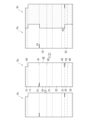
- the trough unit 1u has a first slit 51 that opens at the downstream end LE on the first side 41 and a second slit 52 that opens on the fourth side 44 at the upstream end UE.
- the lengths of the first slit 51 and the second slit 52 are the same, and are 1/5 to 1/10 of the length of the trough unit 1u in the longitudinal direction.
- the trough unit 1u has a notch 55 at the trailing edge 12.
- the notch portion 55 is formed by cutting the rear edge portion 12 by a certain length from the upstream end UE.
- the notched length is the same as the first slit 51 and the second slit 52 .
- the two trough units 1u are adjacent to each other, and the first side 41 of the trough unit 1u on the downstream side is inserted into the first slit 51 of the trough unit 1u on the upstream side to become the downstream side.
- the connection can be made by inserting the fourth side 44 of the trough unit 1u on the upstream side into the second slit 52 of the trough unit 1u.
- the trough unit 1u on the upstream side is called “upstream unit 1u”
- the trough unit 1u on the downstream side is called "downstream unit 1u".
- the portion near the upstream end UE in the downstream unit 1u and the portion near the downstream end LE in the upstream unit 1u overlap by the lengths of the first slit 51 and the second slit 52.
- the upstream unit 1u is downstream of the bottom surface portion 10, the first front surface portion 21, the second front surface portion 22, the first hook portion 31, and the second hook portion 32.
- the unit 1u is covered from above, and in the rear surface portion 11 and the third hook portion 33, the downstream unit 1u covers the upstream unit 1u from above.
- the upstream unit 1u is covered from above, and the upstream unit 1u covers the downstream unit 1u from above at the rear surface portion 11 and the third hook portion 33 .
- FIGS. 3 and 4 show the connected state of the trough unit 1u
- the trough unit 1u on the upstream side is shaded in order to clearly show the overlap. This also applies to FIGS. 5 to 8, which will be described later.
- the chain 180 of the chain feeder slides on the bottom surface portion 10 in the direction from the upstream unit 1u to the downstream unit 1u. Therefore, as shown in FIG. 4, if the downstream unit 1u covers the upstream unit 1u from above on the bottom surface 10, the chain 180 may get caught on the step at the boundary between them and may not slide smoothly. Therefore, as shown in FIG. 3, the two trough units 1u are connected so that the upstream unit 1u covers the downstream unit 1u on the bottom surface 10 from above.
- the trough units 1u having the same configuration can be easily manufactured.
- the trough unit 1u has a notch 55 on the upstream end UE side of the trailing edge 12 . If the notch 55 were not present, the downstream unit 1u would cover the upstream unit 1u from above at both the rear and front ends of the connecting portion of the two trough units 1u. Become. Therefore, in a long feeding trough 1 in which many trough units 1u are continuously connected, even if one trough unit 1u needs to be replaced, it is difficult to remove only that trough unit 1u.
- the rear edge portions 12, which are the rear ends do not overlap each other, so both trough units 1u are slightly elastically deformed at the connecting portion. Thus, only one trough unit 1u can be removed, and similarly, only a new trough unit 1u can be installed by inserting it.
- the notch portion 55 is provided at the upstream end UE of the trailing edge portion 12 of the trough unit 1u, it may be provided at the downstream end LE of the trailing edge portion 12 of the trough unit 1u. , the same effects are exhibited.
- FIG. 3 illustrates a trough unit 1u in which the first slit 51 opens at the downstream end LE on the first side 41 and the second slit 52 opens on the fourth side 44 at the upstream end UE.
- the first slit 51 opens at the upstream end UE on the first side 41
- the second slit 52 opens at the downstream end LE on the fourth side 44.
- the trough unit 2u can be configured as follows. Except for the opening directions of the first slit 51 and the second slit 52, the configuration of the trough unit 2u is the same as that of the trough unit 1u. Even in the trough unit 2u having such a configuration, as shown in the right diagram of FIG.
- connection state is the same as the connection state of the trough unit 1u shown in FIG.
- the upstream unit 2u covers the downstream unit 2u from above in the second front surface portion 22, the first hook portion 31, and the second hook portion 32, and the downstream unit 2u covers the rear surface portion 11 and the third hook portion 33.
- the upstream unit 2u can be covered from above.
- the notch portion 55 is provided at the upstream end UE of the trailing edge portion 12, but the notch portion 55 is provided at the downstream end LE of the trailing edge portion 12.
- the good thing is the same as the trough unit 1u described above. This is the same for trough units of other aspects described later.
- the first slit 51 and the second slit 52 are opened in opposite directions
- a case where one of the second slits 52 is open at the downstream end LE and the other is open at the upstream end UE is illustrated.
- the first slit 51 and the second slit 52 may be opened in the same direction.
- the first slit 51 opens at the upstream end UE on the first side 41
- the second slit 52 opens on the fourth side 44 at the upstream end UE. It can be a unit 3u.
- the configuration of the trough unit 3u is the same as that of the trough units 1u and 2u except that the first slit 51 and the second slit 52 open in the same direction.
- a trough unit having a configuration in which the first slit 51 opens at the downstream end LE on the first side 41 and the second slit 52 opens at the downstream end LE on the fourth side 44. can be Even with such a configuration, the same connection state as the state shown in the right figures in FIGS. 3 and 5 can be obtained.
- the trough units 1u, 2u, and 3u provided with two slits are exemplified for connecting the adjacent trough units. Even if there are three or more slits opening at the upstream end UE or the downstream end LE, it is possible to connect adjacent trough units using those slits. However, an increase in the number of slits complicates the manufacturing process of the trough unit, increases the cost, and increases the work required for connection. Therefore, the number of slits is set to two in this embodiment. If the number of slits is one, the connection state may become unstable, and the minimum number of slits for stable connection is two.
- the bottom portion 10 is the lowest portion, so the first slit 51 is long in the bottom portion 10.
- the high portions are the second hook portion 32 and the high edge portion 12, but the second hook portion 32 is selected as the high portion because the connection state is more stable when the two slits are separated.
- the second slit 52 is opened at either the upstream end UE or the downstream end LE on either side of the third side 43 and the fourth side 44, which are a pair of sides parallel to the longitudinal direction of the second hook portion 32.
- the second slit 52 is provided so as to open to the upstream end UE on the fourth side 44, similarly to the trough units 1u and 3u, while the first slit 51 is provided at the second A trough unit 4u may be provided at the side 42 so as to open to the downstream end LE. Except for the position of the first slit 51, the configuration of the trough unit 4u is the same as that of the trough units 1u and 3u. Even with the trough unit 4u having such a configuration, as shown in the right diagram of FIG. Is possible.
- the birds reared in the cage are fed to the food near the cage, that is, to the first side 41. They tend to eat food that is close to them. Therefore, in the bottom surface portion 10 , the portion closer to the second side 42 is more likely to corrode due to the retention of the bait than the portion closer to the first side 41 . Therefore, it is preferable to form the first slit 51 in the first side 41 rather than forming the first slit 51 in the second side 42, which is a portion that is likely to corrode.
- the first slit 51 is provided so as to open to the downstream end LE on the first side 41 in the same manner as the trough unit 1u, while the second slit 52 is provided at the third end LE.
- It can be a trough unit 5u that is provided so as to open to the upstream end UE at the side 43 .
- the configuration of the trough unit 4u is the same as that of the trough unit 1u. Even with the trough unit 4u having such a configuration, as shown in the right diagram of FIG. It is possible.
- the two points where the adjacent trough units are engaged are In contrast to P1 and P2 (see FIG. 3), in the trough unit 5u in which the second slit 52 is formed in the third side 43, the two points where adjacent trough units are engaged are P1 and P3. (see FIG. 8).
- the distance between P1-P2 is longer than the distance between P1-P3. Therefore, the trough unit 1u is more desirable than the trough unit 5u because the connection state is more stable.
- the feeding trough 1 formed by connecting the trough units 1u to 5u as described above is supported from below by a support 190 and held horizontally.
- the support 190 is attached to the frame holding the cage, and includes the rear surface 11, the bottom surface 10, the first front surface 21, the second front surface 22, and the first hooks of the trough units 1u to 5u.
- a concave portion 191 into which the portion 31 can be fitted, and an inverted U-shaped hook portion 30 composed of a first hook portion 31, a second hook portion 32, and a third hook portion 33 are hooked to hook the second hook. It has an upper surface portion 194 on which the portion 32 is placed.
- the connected trough units 1u to 5u are maintained in a connected state by fastening bolts passed through the holes 19 with nuts as described above.
- the bottom portion 10 can be covered from above with a cover plate 160 at that portion.
- a countersunk hole 165 is provided through the center of the cover plate 160, and a countersunk machine screw (not shown) as a bolt is passed through the hole and fastened with a nut so that the head of the bolt does not protrude upward. It's becoming The countersunk machine screws have a function of fixing the superimposed trough units 1u to 5u together and a function of fixing the cover plate 160 to the trough units 1u to 5u.
- the cover plate 160 has an inclined portion whose height gradually rises from the upstream side in order to allow the chain 180 to smoothly ride up, and also has an inclined portion in order to allow the chain 180 to pass smoothly. , with a slope whose height gradually decreases toward the downstream side.
- the trough units 1u to 5u have two slits (the first slit 51 and the second slit 52).
- a feeding trough 1 can be formed.
- the belt-like connector 150 is not required for connecting the trough unit 100u, so the number of parts can be reduced and the manufacturing cost can be reduced. At the same time, the complexity of component management can be reduced.
- the front surface portion 20 is composed of a first front surface portion 21 and a second front surface portion 22, the first front surface portion 21 being perpendicular to the bottom surface portion 10, and the second front surface portion 22 being perpendicular to the bottom surface portion 10. is inclined forward.
- the angles formed between the first front surface portion 21 and the second front surface portion 22 and the bottom surface portion 10 are not limited to those illustrated above.
- the front surface portion 20 may be composed of one plane, or may be composed of three or more planes.
- the rear surface portion 11 is composed of one surface and forms a right angle with the bottom surface portion 10 is exemplified.
- the angle formed by the rear surface portion 11 and the bottom surface portion 10 is not limited to the one exemplified above. Further, the rear surface portion 11 may be composed of two or more flat surfaces.
- the trough unit is provided with three or more slits.
Landscapes
- Life Sciences & Earth Sciences (AREA)
- Environmental Sciences (AREA)
- Birds (AREA)
- Animal Husbandry (AREA)
- Biodiversity & Conservation Biology (AREA)
- Laying Of Electric Cables Or Lines Outside (AREA)
Priority Applications (4)
| Application Number | Priority Date | Filing Date | Title |
|---|---|---|---|
| CN202280090446.0A CN118647266A (zh) | 2022-02-10 | 2022-02-10 | 饲料槽单元的连接方法及饲料槽单元 |
| KR1020247019099A KR20240148313A (ko) | 2022-02-10 | 2022-02-10 | 트로프 유닛의 접속방법 및 트로프 유닛 |
| JP2023579956A JPWO2023152875A1 (https=) | 2022-02-10 | 2022-02-10 | |
| PCT/JP2022/005368 WO2023152875A1 (ja) | 2022-02-10 | 2022-02-10 | トラフユニットの接続方法及びトラフユニット |
Applications Claiming Priority (1)
| Application Number | Priority Date | Filing Date | Title |
|---|---|---|---|
| PCT/JP2022/005368 WO2023152875A1 (ja) | 2022-02-10 | 2022-02-10 | トラフユニットの接続方法及びトラフユニット |
Publications (1)
| Publication Number | Publication Date |
|---|---|
| WO2023152875A1 true WO2023152875A1 (ja) | 2023-08-17 |
Family
ID=87563962
Family Applications (1)
| Application Number | Title | Priority Date | Filing Date |
|---|---|---|---|
| PCT/JP2022/005368 Ceased WO2023152875A1 (ja) | 2022-02-10 | 2022-02-10 | トラフユニットの接続方法及びトラフユニット |
Country Status (4)
| Country | Link |
|---|---|
| JP (1) | JPWO2023152875A1 (https=) |
| KR (1) | KR20240148313A (https=) |
| CN (1) | CN118647266A (https=) |
| WO (1) | WO2023152875A1 (https=) |
Citations (7)
| Publication number | Priority date | Publication date | Assignee | Title |
|---|---|---|---|---|
| JPS59136956U (ja) * | 1983-03-04 | 1984-09-12 | 大可工業株式会社 | 養鶏用餌樋装置 |
| JPS6456655U (https=) * | 1987-09-30 | 1989-04-10 | ||
| JPH10108579A (ja) * | 1996-10-02 | 1998-04-28 | Toyo Syst Kk | ケージシステム |
| JP2005304402A (ja) * | 2004-04-22 | 2005-11-04 | Fujii Shokai:Kk | 養鶏用飼料供給装置 |
| KR20160043694A (ko) * | 2014-10-14 | 2016-04-22 | 이범성 | 아파트형 케이지의 사료 공급장치 |
| WO2020035891A1 (ja) * | 2018-08-13 | 2020-02-20 | 株式会社ハイテム | トラフの支持構造及び支持具 |
| WO2021079454A1 (ja) * | 2019-10-24 | 2021-04-29 | 株式会社ハイテム | 給餌装置 |
Family Cites Families (4)
| Publication number | Priority date | Publication date | Assignee | Title |
|---|---|---|---|---|
| JP2005229951A (ja) * | 2004-02-23 | 2005-09-02 | Fujii Shokai:Kk | 養鶏用自動給餌装置 |
| CN206078577U (zh) * | 2016-08-31 | 2017-04-12 | 广州广兴牧业设备集团有限公司 | 一种喂料料槽 |
| CN206442925U (zh) * | 2017-01-13 | 2017-08-29 | 安徽瑞格电子科技有限公司 | 笼养设备自支撑料槽 |
| CN206808422U (zh) * | 2017-06-07 | 2017-12-29 | 河南中州牧业养殖设备有限公司 | 层叠式蛋鸡饲养设备的缩口食槽 |
-
2022
- 2022-02-10 CN CN202280090446.0A patent/CN118647266A/zh active Pending
- 2022-02-10 KR KR1020247019099A patent/KR20240148313A/ko active Pending
- 2022-02-10 JP JP2023579956A patent/JPWO2023152875A1/ja active Pending
- 2022-02-10 WO PCT/JP2022/005368 patent/WO2023152875A1/ja not_active Ceased
Patent Citations (7)
| Publication number | Priority date | Publication date | Assignee | Title |
|---|---|---|---|---|
| JPS59136956U (ja) * | 1983-03-04 | 1984-09-12 | 大可工業株式会社 | 養鶏用餌樋装置 |
| JPS6456655U (https=) * | 1987-09-30 | 1989-04-10 | ||
| JPH10108579A (ja) * | 1996-10-02 | 1998-04-28 | Toyo Syst Kk | ケージシステム |
| JP2005304402A (ja) * | 2004-04-22 | 2005-11-04 | Fujii Shokai:Kk | 養鶏用飼料供給装置 |
| KR20160043694A (ko) * | 2014-10-14 | 2016-04-22 | 이범성 | 아파트형 케이지의 사료 공급장치 |
| WO2020035891A1 (ja) * | 2018-08-13 | 2020-02-20 | 株式会社ハイテム | トラフの支持構造及び支持具 |
| WO2021079454A1 (ja) * | 2019-10-24 | 2021-04-29 | 株式会社ハイテム | 給餌装置 |
Also Published As
| Publication number | Publication date |
|---|---|
| CN118647266A (zh) | 2024-09-13 |
| KR20240148313A (ko) | 2024-10-11 |
| JPWO2023152875A1 (https=) | 2023-08-17 |
Similar Documents
| Publication | Publication Date | Title |
|---|---|---|
| CN101877960B (zh) | 水产养殖筐和附接系统 | |
| USRE46401E1 (en) | Concave with an array of longitudinally notched spaced apart threshing elements | |
| KR100226536B1 (ko) | 개방 힌지핀 구조를 갖는 모듈식 컨베이어 벨트 및 이벨트에 사용되는 모듈 | |
| US20150150238A1 (en) | Bird Spike With Plastic Base Having Upper Recesses | |
| US6079543A (en) | Lane-divided plastic conveyor belt | |
| US10308436B2 (en) | Modular conveyor belt with attached plates | |
| WO2023152875A1 (ja) | トラフユニットの接続方法及びトラフユニット | |
| US20190263593A1 (en) | Modular Eye Link Conveyor Belt | |
| JP2003012134A (ja) | 平格子形ベルトモジュール | |
| JP7701066B2 (ja) | 給餌用トラフ構造及び給餌用補助具 | |
| CN108883876B (zh) | 用于模块化塑料输送带的驱动和侧挡板带插设件 | |
| US3180319A (en) | Hog trough | |
| CN101878169A (zh) | 用于模块化带的可交换的连接件和连接件保持器 | |
| JP7002789B2 (ja) | トラフの支持構造及び支持具 | |
| FR2612972A1 (fr) | Panneau de plancher | |
| US11497195B2 (en) | Poultry behavioral development system | |
| US4195592A (en) | Poultry cage system | |
| US3478721A (en) | Brooding and growing cage | |
| JP7207791B2 (ja) | 給餌装置 | |
| NL9200942A (nl) | Kooienbatterij. | |
| CN220431557U (zh) | 一种蛋类排列装置 | |
| US3800739A (en) | Feed saver for a poultry egg laying battery | |
| DE202013002291U1 (de) | Geflügelaufstandsrost mit Sitzstange zur Geflügelhaltung | |
| JP2026002377A (ja) | 爪とぎ | |
| CN114929015A (zh) | 多层家禽护笼的翻倒防止构造 |
Legal Events
| Date | Code | Title | Description |
|---|---|---|---|
| 121 | Ep: the epo has been informed by wipo that ep was designated in this application |
Ref document number: 22925896 Country of ref document: EP Kind code of ref document: A1 |
|
| ENP | Entry into the national phase |
Ref document number: 2023579956 Country of ref document: JP Kind code of ref document: A |
|
| WWE | Wipo information: entry into national phase |
Ref document number: 202427056045 Country of ref document: IN |
|
| WWE | Wipo information: entry into national phase |
Ref document number: 202280090446.0 Country of ref document: CN |
|
| NENP | Non-entry into the national phase |
Ref country code: DE |
|
| 32PN | Ep: public notification in the ep bulletin as address of the adressee cannot be established |
Free format text: NOTING OF LOSS OF RIGHTS PURSUANT TO RULE 112(1) EPC (EPO FORM 1205A DATED 19.11.2024) |
|
| 122 | Ep: pct application non-entry in european phase |
Ref document number: 22925896 Country of ref document: EP Kind code of ref document: A1 |