WO2023148917A1 - 空気調和用熱交換器 - Google Patents
空気調和用熱交換器 Download PDFInfo
- Publication number
- WO2023148917A1 WO2023148917A1 PCT/JP2022/004387 JP2022004387W WO2023148917A1 WO 2023148917 A1 WO2023148917 A1 WO 2023148917A1 JP 2022004387 W JP2022004387 W JP 2022004387W WO 2023148917 A1 WO2023148917 A1 WO 2023148917A1
- Authority
- WO
- WIPO (PCT)
- Prior art keywords
- hairpin
- peripheral surface
- straight pipe
- hydrophilic
- heat exchanger
- Prior art date
- Legal status (The legal status is an assumption and is not a legal conclusion. Google has not performed a legal analysis and makes no representation as to the accuracy of the status listed.)
- Ceased
Links
Images




Classifications
-
- F—MECHANICAL ENGINEERING; LIGHTING; HEATING; WEAPONS; BLASTING
- F28—HEAT EXCHANGE IN GENERAL
- F28F—DETAILS OF HEAT-EXCHANGE AND HEAT-TRANSFER APPARATUS, OF GENERAL APPLICATION
- F28F19/00—Preventing the formation of deposits or corrosion, e.g. by using filters or scrapers
- F28F19/02—Preventing the formation of deposits or corrosion, e.g. by using filters or scrapers by using coatings, e.g. vitreous or enamel coatings
-
- F—MECHANICAL ENGINEERING; LIGHTING; HEATING; WEAPONS; BLASTING
- F28—HEAT EXCHANGE IN GENERAL
- F28F—DETAILS OF HEAT-EXCHANGE AND HEAT-TRANSFER APPARATUS, OF GENERAL APPLICATION
- F28F9/00—Casings; Header boxes; Auxiliary supports for elements; Auxiliary members within casings
- F28F9/007—Auxiliary supports for elements
- F28F9/013—Auxiliary supports for elements for tubes or tube-assemblies
Definitions
- the present disclosure relates to an air-conditioning heat exchanger that includes a holder that accommodates hairpin portions of heat transfer tubes.
- An air conditioning heat exchanger comprising a plurality of fins, a heat transfer tube having one end bent at a hairpin portion and penetrating the plurality of fins, and a holder for housing the hairpin portion of the heat transfer tube.
- Patent Literature 1 describes an air-conditioning heat exchanger provided with a holder having effects such as ensuring strength, optimizing air passages, and preventing corrosion at hairpin portions.
- Patent Document 1 In the air-conditioning heat exchanger as described in Patent Document 1, condensed water generated on the surface of the heat exchanger during cooling operation is trapped by surface tension in the gap between the hairpin portion and the inner peripheral surface of the holder. There is a concern that corrosion will occur at the hairpin portion because it continues to stay. Therefore, in Patent Document 1, it is proposed to prevent the condensed water from accumulating by sufficiently opening a gap between the hairpin portion and the inner peripheral surface of the holder so that the condensed water can flow down, thereby avoiding the occurrence of corrosion. ing.
- the condensed water that adheres to the hairpin tends to gather in the vertical direction of the hairpin due to gravity. Therefore, even if there is a sufficient gap between the hairpin portion and the inner peripheral surface of the holder, the condensed water may collect and continue to remain due to the surface tension while blocking the gap. Also, the condensed water falling from the hairpin portion is received by the bottom surface of the holder. Therefore, even when the condensed water falls from the hairpin portion, the condensed water may continue to remain in a state where the gap between the heat transfer tube and the bottom surface of the holder is closed. Therefore, the condensed water remains in the gap between the heat transfer tube and the inner peripheral surface of the holder for a long time, which may cause corrosion in the hairpin portion.
- the present disclosure has been made to solve the above problems, and provides an air-conditioning heat exchanger that suppresses the occurrence of corrosion in the hairpin portions of the heat transfer tubes.
- An air-conditioning heat exchanger includes a plurality of fins arranged at intervals in a first direction, and a hairpin portion provided penetrating the plurality of fins and folded at an end portion in the first direction. and a holder having a cylindrical portion in which the hairpin portion is accommodated, the heat transfer tube having a first straight pipe portion and a second straight pipe portion arranged in the vertical direction, the first straight pipe portion , located above the second straight pipe portion, the hairpin portion is provided between the first straight pipe portion and the second straight pipe portion, and connects the first straight pipe portion and the second straight pipe portion,
- the outer peripheral surface of the hairpin portion has a first hydrophilic portion formed with a hydrophilic film in a portion positioned above the axis of the second straight pipe portion in the vertical direction, and the inner circumference of the bottom portion of the tubular portion.
- the surface has a second hydrophilic portion with a hydrophilic coating formed thereon.
- the hairpin portion of the heat transfer tube has the first hydrophilic portion formed with a hydrophilic coating on the outer peripheral surface located above the axis of the second straight pipe portion.
- the cylindrical portion of the holder in which the hairpin portion is accommodated has a second hydrophilic portion formed with a hydrophilic coating on the inner peripheral surface of the bottom portion.
- the second hydrophilic portion facilitates the movement of condensed water, and prevents the condensed water from staying so as to close the gap between the inner peripheral surface of the holder and the outer peripheral surface of the hairpin portion. . Therefore, it is possible to prevent the dew condensation water from adhering to the hairpin portion of the heat transfer tube for a long period of time, thereby suppressing the occurrence of corrosion in the hairpin portion.
- FIG. 1 is a circuit diagram showing an air conditioner according to Embodiment 1.
- FIG. 1 is a perspective view showing an air-conditioning heat exchanger according to Embodiment 1.
- FIG. 4 is a front view of the holder according to Embodiment 1.
- FIG. 4 is a partial perspective view of the cylindrical portion of the holder and the heat transfer tube according to Embodiment 1.
- FIG. 4 is a simplified front view showing a tubular portion and a hairpin portion of the holder according to Embodiment 1;
- 2 is a schematic diagram showing a hydrophilic portion according to Embodiment 1;
- FIG. FIG. 4 is a schematic vertical cross-sectional view taken along the line AA of FIG.
- FIG. 3; 4 is a schematic diagram showing a state in which condensed water remains between the outer peripheral surface of the hairpin portion and the inner peripheral surface of the cylindrical portion of the holder in Embodiment 1.
- FIG. FIG. 8 is a schematic diagram showing a water-repellent portion according to Embodiment 2;
- FIG. 8 is a schematic vertical cross-sectional view of a holder and a heat transfer tube according to Embodiment 2;
- FIG. 1 is a circuit diagram showing an air conditioner 1 according to Embodiment 1.
- the air conditioner 1 is a device that adjusts indoor air, and includes an outdoor unit 2 and an indoor unit 3 .
- the outdoor unit 2 is provided with, for example, a compressor 6 , a flow path switching device 7 , an outdoor heat exchanger 8 , an outdoor fan 9 , and an expansion section 10 .
- the indoor unit 3 is provided with, for example, an air-conditioning heat exchanger 11 and a fan 12 .
- a refrigerant circuit 4 is configured by connecting the compressor 6 , the flow path switching device 7 , the outdoor heat exchanger 8 , the expansion section 10 , and the air-conditioning heat exchanger 11 through refrigerant pipes 5 .
- the compressor 6 sucks in a low-temperature, low-pressure refrigerant, compresses the sucked-in refrigerant, converts it into a high-temperature, high-pressure refrigerant, and discharges it.
- the flow switching device 7 switches the direction in which the refrigerant flows in the refrigerant circuit 4, and is, for example, a four-way valve.
- the outdoor heat exchanger 8 exchanges heat, for example, between outdoor air and refrigerant.
- the outdoor heat exchanger 8 acts as a condenser during cooling operation and dehumidifying operation, and acts as an evaporator during heating operation.
- the outdoor fan 9 is a device that sends outdoor air to the outdoor heat exchanger 8 .
- the expansion section 10 is a pressure reducing valve or an expansion valve that reduces the pressure of the refrigerant to expand it.
- the expansion section 10 is, for example, an electronic expansion valve whose opening is adjusted.
- the air-conditioning heat exchanger 11 exchanges heat, for example, between indoor air and refrigerant.
- the air-conditioning heat exchanger 11 acts as an evaporator during cooling and dehumidifying operations, and acts as a condenser during heating operation.
- the blower 12 is a device that sends indoor air to the heat exchanger 11 for air conditioning.
- the condensed liquid refrigerant flows into the expansion section 10, where it is expanded and decompressed to become a low-temperature, low-pressure gas-liquid two-phase refrigerant. Then, the gas-liquid two-phase refrigerant flows into the air-conditioning heat exchanger 11 acting as an evaporator, where it is heat-exchanged with the room air sent by the blower 12 to evaporate. to gasify. At this time, the room air is cooled, so that the room is cooled or dehumidified. The vaporized low-temperature, low-pressure gaseous refrigerant passes through the flow switching device 7 and is sucked into the compressor 6 .
- heating operation Next, the heating operation will be explained.
- the refrigerant sucked into the compressor 6 is compressed by the compressor 6 and discharged in a high-temperature and high-pressure gas state.
- the high-temperature and high-pressure gaseous refrigerant discharged from the compressor 6 passes through the flow path switching device 7 and flows into the air-conditioning heat exchanger 11 acting as a condenser. , it is heat-exchanged with the indoor air sent by the blower 12 to condense and liquefy. At this time, indoor air is warmed, and heating is carried out in the room.
- the condensed liquid refrigerant flows into the expansion section 10, where it is expanded and decompressed to become a low-temperature, low-pressure gas-liquid two-phase refrigerant. Then, the gas-liquid two-phase refrigerant flows into the outdoor heat exchanger 8 that acts as an evaporator, and in the outdoor heat exchanger 8, heat is exchanged with the outdoor air sent by the outdoor fan 9 to evaporate and gasify. do.
- the vaporized low-temperature, low-pressure gaseous refrigerant passes through the flow switching device 7 and is sucked into the compressor 6 .
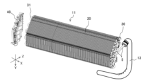
- FIG. 2 is a perspective view showing the air-conditioning heat exchanger 11 according to Embodiment 1.
- the first direction X is the width direction of the air-conditioning heat exchanger 11 .
- the second direction Y indicates the vertical direction of the air-conditioning heat exchanger 11 .
- the third direction Z is the front-rear direction of the air-conditioning heat exchanger 11 .
- the air-conditioning heat exchanger 11 includes multiple fins 20 , multiple heat transfer tubes 30 , and a holder 40 .
- fin 20 The plurality of fins 20 are arranged side by side at intervals in the first direction X, which is the width direction of the air-conditioning heat exchanger 11 .
- the indoor air drawn into the air-conditioning heat exchanger 11 passes through the plurality of fins 20 .
- the heat transfer tubes 30 are made of metal, for example, and provided so as to penetrate the plurality of fins 20 .
- the heat transfer tube 30 has a hairpin portion 31 that is folded back at the end in the first direction X. As shown in FIG. The hairpin portion 31 is bent at 180 degrees with a predetermined curvature.
- refrigerant flows inside the heat transfer tubes 30 .
- a part of the heat transfer tube 30 is exposed between the plurality of fins 20 arranged in the first direction X.
- the room air passing between the plurality of fins 20 hits the heat transfer tubes 30, and heat exchange is performed between the refrigerant flowing inside the heat transfer tubes 30 and the room air.
- the heat transfer tube 30 has a cylindrical shape.
- a refrigerant pipe 5 is connected to a portion of the heat transfer pipe 30 at one end in the first direction X. As shown in FIG.
- the refrigerant pipe 5 is covered with a pipe cover 13 .
- the refrigerant pipe 5 is protected by a pipe cover 13 and insulated from the outside air.
- the holder 40 is provided at one end in the first direction X in the unit in which the fins 20 and the heat transfer tubes 30 are combined, as shown in FIG.
- the end in the first direction X where the holder 40 is provided is the end opposite to the end where the refrigerant pipe 5 is connected to the heat transfer tube 30 .
- the holder 40 has a function of securing the strength of the air-conditioning heat exchanger 11 and protecting the hairpin portion 31 of the heat transfer tube 30 .
- the holder 40 is made of resin, for example.
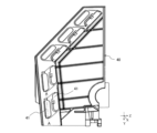
- FIG. 3 is a front view of the holder 40 according to Embodiment 1.
- FIG. FIG. 4 is a partial perspective view of cylindrical portion 42 of holder 40 and heat transfer tube 30 according to the first embodiment.
- FIG. 4 shows the outlines of the holder 40, the fins 20, and the heat transfer tubes 30 in a simplified manner.
- FIG. 5 is a simplified front view showing cylindrical portion 42 and hairpin portion 31 of holder 40 according to the first embodiment.
- FIG. 5 shows a portion of the holder 40 extracted.
- FIG. 6 is a schematic diagram showing the hydrophilic portion 51 according to the first embodiment.
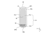
- FIG. 7 is a schematic vertical cross-sectional view taken along line AA of FIG.
- the holder 40 has an opening 41. Further, as shown in FIG. 4 , a cylindrical portion 42 of the holder 40 protrudes outward in the first direction X from the edge of the opening 41 of the holder 40 .
- the outside in the first direction X refers to the side opposite to the side where the fins 20 are located.
- the holder 40 has a cylindrical opening 43 facing the opening 41 .
- the heat transfer tube 30 has a first straight pipe portion 33 and a second straight pipe portion 34 arranged vertically.
- the first straight pipe portion 33 is positioned above the second straight pipe portion 34 .
- the hairpin portion 31 is provided between the first straight pipe portion 33 and the second straight pipe portion 34 and connects the first straight pipe portion 33 and the second straight pipe portion 34 .
- the top portion 32 of the hairpin portion 31 is positioned between the first straight pipe portion 33 and the second straight pipe portion 34 in the vertical direction.
- a portion of the heat transfer tube 30 that is accommodated in the cylindrical portion 42 of the holder 40 is called a hairpin portion 31 .
- the hairpin portion 31 includes a bent portion and a straight tube portion.
- the hairpin portion 31 of the heat transfer tube 30 is inserted into the opening 41 of the holder 40 and housed in the tubular portion 42 of the holder 40 .
- a portion of the outer peripheral surface 31a of the hairpin portion 31 and a portion of the inner peripheral surface 42a of the cylindrical portion 42 face each other.
- the cylindrical portion 42 has a bottom portion 42b.
- the tubular portion opening 43 is provided in the tubular portion 42 .
- a second hydrophilic portion 51b which will be described later, is provided on the inner peripheral surface 42a of the bottom portion 42b of the cylindrical portion 42.
- the hairpin portion 31 of the heat transfer tube 30 has a top portion 32 at the end portion in the first direction X.
- the apex 32 is the apex of the bent portion of the hairpin portion 31 .
- the hairpin portion 31 is housed in the tubular portion 42 of the holder 40 without protruding from the tubular portion 42 . Therefore, when the air-conditioning heat exchanger 11 is viewed in the front-rear direction, that is, in the third direction Z, the hairpin portion 31 is covered with the tubular portion 42 and is not visible. Since the hairpin portion 31 is housed in the cylindrical portion 42, it is less likely to be affected by the outside. In other words, the tubular portion 42 of the holder 40 protects the hairpin portion 31 . 4 to 7, one hairpin portion 31 is accommodated in one cylindrical portion 42. As shown in FIG. However, although not shown, a configuration may be adopted in which a plurality of hairpin portions 31 are housed in one tubular portion 42 .
- the tubular portion 42 of the holder 40 optimizes the airflow path of the air flowing through the heat exchanger 11 for air conditioning.
- the tubular portion 42 has the fins 20 instead of the air flowing into the air-conditioning heat exchanger 11 flowing in the third direction Z at the side portion of the air-conditioning heat exchanger 11 where the hairpin portion 31 is arranged.
- the air is made to flow in the first direction X toward the central portion of the air-conditioning heat exchanger 11 .
- the hydrophilic portion 51 of the outer peripheral surface 31a of the hairpin portion 31 and the inner peripheral surface 42a of the cylindrical portion 42 will be described with reference to FIGS. 6 and 7.
- FIG. 1 the outer peripheral surface 31a of the hairpin portion 31 has a first hydrophilic portion 51a formed by applying a hydrophilic film.
- the inner peripheral surface 42a of the tubular portion 42 has a second hydrophilic portion 51b formed by applying a hydrophilic film.
- hydrophilic portion 51 when there is no particular need to distinguish between the first hydrophilic portion 51a and the second hydrophilic portion 51b, they are simply referred to as "hydrophilic portion 51".
- hydrophilic portion 51 when used, both singular and plural portions are included.
- the hydrophilic film of the hydrophilic portion 51 is applied to the outer peripheral surface 31a of the hairpin portion 31 and the inner peripheral surface 42a of the cylindrical portion 42 by spray coating or brush coating, for example.
- not all of the outer peripheral surface 31a of the hairpin portion 31 has the first hydrophilic portion 51a, and all of the inner peripheral surface 42a of the cylindrical portion 42 has the second hydrophilic portion 51b. does not have.
- the first hydrophilic portion 51a of the outer peripheral surface 31a of the hairpin portion 31 is It is provided above the axis AX.
- the first hydrophilic portion 51a is not provided on the outer peripheral surface 31a of the hairpin portion 31 located below the axis AX in the vertical direction.
- the second hydrophilic portion 51b is provided below the axis AX on the inner peripheral surface 42a of the tubular portion 42. As shown in FIG. In other words, the second hydrophilic portion 51b is not provided on the inner peripheral surface 42a of the cylindrical portion 42 located above the axis AX in the vertical direction.
- the first hydrophilic portion 51a may not be provided in a portion of the outer peripheral surface 31a of the hairpin portion 31 located above the axis AX that does not face the inner peripheral surface 42a of the cylindrical portion 42.
- the first hydrophilic portion 51a may not be provided on the outer peripheral surface 31a of the bottom surface.
- the first hydrophilic portion 51a may not be provided on the outer peripheral surface 31a of the upper surface.
- the first hydrophilic portion 51a may not be provided on the outer peripheral surface 31a of the bent portion between the bottom surface of the upper straight pipe portion of the hairpin portion 31 and the upper surface of the lower straight pipe portion.
- the gap between the outer peripheral surface 31a of the hairpin portion 31 located above the axis AX and the inner peripheral surface 42a of the cylindrical portion 42 having the first hydrophilic portion 51a will be referred to as the gap SP1.
- a gap between the outer peripheral surface 31a of the hairpin portion 31 located below the axis AX and the inner peripheral surface 42a of the cylindrical portion 42, which does not have the first hydrophilic portion 51a is referred to as a gap SP2.
- gap SP1 and the gap SP2 are simply referred to as the "gap SP".
- the second hydrophilic portion 51b may be provided on the inner peripheral surface 42a of the bottom surface portion 42b of the tubular portion 42, as shown in FIGS. More preferably, the second hydrophilic portion 51b is provided in a portion of the inner peripheral surface 42a of the cylindrical portion 42 that faces the outer peripheral surface 31a of the hairpin portion 31 and faces the portion where the first hydrophilic portion 51a is not provided. Good. Further, when the second hydrophilic portion 51b is projected onto the outer peripheral surface 31a of the hairpin portion 31, the portion of the first hydrophilic portion 51a located below the axis AX does not overlap with the projected area of the second hydrophilic portion 51b. . That is, when the second hydrophilic portion 51b is projected onto the outer peripheral surface 31a of the hairpin portion 31, the first hydrophilic portion 51a is not provided in the projection area.
- the hydrophilic portion 51 prevents the condensed water 50 from remaining in a state of blocking the gap SP between the outer peripheral surface 31 a of the hairpin portion 31 and the inner peripheral surface 42 a of the cylindrical portion 42 .
- FIG. 8 is a schematic diagram showing a state in which condensed water 50 remains between the outer peripheral surface 31a of the hairpin portion 31 and the inner peripheral surface 42a of the tubular portion 42 of the holder 40 in the first embodiment.
- the heat transfer tubes 30 are cooled by the refrigerant flowing inside the heat transfer tubes 30 .
- the humidity around the heat transfer tube 30 is high, dew condensation may occur on the surface of the heat transfer tube 30 .
- the condensed water 50 straddled the gap SP between the outer peripheral surface 31a of the hairpin portion 31 and the inner peripheral surface 42a of the cylindrical portion 42. adhere to the state. That is, the condensed water 50 closes the gap SP. In such a state, the condensed water 50 becomes difficult to move and stays in the gap SP for a long time.
- the condensed water 50 since the hydrophilic portion 51 is provided in a part of the portion where the gap SP contacts, the condensed water 50 preferentially moves to the hydrophilic portion 51 . Therefore, it is difficult for the condensed water 50 to stay in one place in the gap SP1 between the outer peripheral surface 31a of the hairpin portion 31 having the first hydrophilic portion 51a and the inner peripheral surface 42a of the tubular portion 42 . Also, the condensed water 50 flows vertically along the outer peripheral surface 31a of the hairpin portion 31 due to gravity and gathers. Since the heat transfer tube 30 has a cylindrical shape, the condensed water 50 tends to collect on the outer peripheral surface 31 a of the bottom surface of the straight tube portion of the hairpin portion 31 .
- the condensed water 50 is less likely to remain in the gap SP1 between the outer peripheral surface 31a of the hairpin portion 31 located above the axis AX and the inner peripheral surface 42a of the tubular portion 42 . Further, since the contact angle of the condensed water 50 is small in the first hydrophilic portion 51a, a large amount of the condensed water 50 needs to gather in order for the condensed water 50 to block the gap SP. However, the gap SP1 between the outer peripheral surface 31a of the hairpin portion 31 located above the axis AX and the inner peripheral surface 42a of the tubular portion 42 is difficult for the condensed water 50 to stay in, so the gap SP1 is blocked by the condensed water 50. is suppressed.
- the condensed water 50 dropped from the hairpin portion 31 is received by the inner peripheral surface 42a of the bottom portion 42b of the cylindrical portion 42. Since the inner peripheral surface 42a of the bottom surface portion 42b of the cylindrical portion 42 is provided with the second hydrophilic portion 51b, the contact angle of the condensed water 50 is small. A large amount of the condensed water 50 needs to gather in order for the condensed water 50 to close the gap SP2, but it is difficult for a large amount of the condensed water 50 to stay in one place in the second hydrophilic portion 51b.
- the first hydrophilic portion 51a of the hairpin portion 31 is not provided on the opposite side of the second hydrophilic portion 51b.
- the condensed water 50 adheres to the gap SP2 between the inner peripheral surface 42a of the bottom surface portion 42b of the cylindrical portion 42 and the outer peripheral surface 31a of the hairpin portion 31, the condensed water 50 It moves preferentially to the second hydrophilic portion 51b. Therefore, between the inner peripheral surface 42a of the bottom surface portion 42b of the cylindrical portion 42 and the outer peripheral surface 31a of the hairpin portion 31, the condensed water 50 is less likely to stay in a state of closing the gap SP2.
- the air-conditioning heat exchanger 11 includes the plurality of fins 20 arranged at intervals in the first direction X, and the plurality of fins 20 penetrating the , a heat transfer tube 30 having a hairpin portion 31 folded back at the end in the first direction X, and a holder 40 having a cylindrical portion 42 in which the hairpin portion 31 is accommodated.
- the heat transfer tube 30 has a first straight pipe portion 33 and a second straight pipe portion 34 arranged vertically. is provided between the first straight pipe portion 33 and the second straight pipe portion 34 and connects the first straight pipe portion 33 and the second straight pipe portion 34 .
- the outer peripheral surface 31 a of the hairpin portion 31 has a first hydrophilic portion 51 a formed with a hydrophilic coating in a portion positioned above the axis AX of the second straight pipe portion 34 in the vertical direction.
- the inner peripheral surface 42a of the bottom surface portion 42b of has a second hydrophilic portion 51b formed with a hydrophilic film.
- the outer peripheral surface 31a of the hairpin portion 31 of the heat transfer tube 30 located above the axis AX in the vertical direction has the first hydrophilic portion 51a.
- the inner peripheral surface 42a of the cylindrical portion 42 located above the axis AX does not have the second hydrophilic portion 51b. Therefore, in the gap SP1 between the outer peripheral surface 31a of the hairpin portion 31 and the inner peripheral surface 42a of the tubular portion 42 located above the axis AX, the condensed water 50 preferentially moves to the first hydrophilic portion 51a. . Therefore, above the axis AX, it is difficult for the condensed water 50 to remain in a state in which the gap SP1 is closed.
- the condensed water 50 flows vertically on the outer peripheral surface 31a of the hairpin portion 31 and gathers, so that the condensed water 50 tends to drop from the outer peripheral surface 31a of the hairpin portion 31 due to gravity. Also, the condensed water 50 dropped from the hairpin portion 31 is received by the inner peripheral surface 42a of the bottom surface portion 42b of the cylindrical portion 42, and preferentially moves to the second hydrophilic portion 51b. Therefore, the gap SP2 between the inner peripheral surface 42a of the bottom surface portion 42b of the cylindrical portion 42 and the outer peripheral surface 31a of the hairpin portion 31 facing each other is not easily blocked by the condensed water 50.
- the first hydrophilic portion 51a is not provided in the area where the second hydrophilic portion 51b is projected onto the outer peripheral surface 31a of the hairpin portion 31 .
- the second hydrophilic portion 51b is provided on a portion of the outer peripheral surface 31a of the hairpin portion 31 that faces the portion that does not have the first hydrophilic portion 51a. Condensed water 50 dropped from the outer peripheral surface 31a of the hairpin portion 31 located above the axis AX may adhere to the outer peripheral surface 31a of the hairpin portion 31 located below the axis AX.
- the outer peripheral surface 31 a of the hairpin portion 31 located below the axis AX does not have the hydrophilic portion 51 . Therefore, the condensed water 50 that has fallen and the condensed water 50 that has originally adhered are likely to gather, and the condensed water 50 is likely to adhere across the gap SP2.
- the inner peripheral surface 42a of the tubular portion 42 has the second hydrophilic portion 51b, the condensed water 50 preferentially moves to the second hydrophilic portion 51b. Therefore, it is possible to prevent the condensed water 50 from blocking the gap SP2 between the outer peripheral surface 31a of the hairpin portion 31 and the inner peripheral surface 42a of the cylindrical portion 42 below the axis AX. Therefore, it is possible to prevent the dew condensation water 50 from adhering to the outer peripheral surface 31a of the hairpin portion 31 located below the axis AX for a long period of time.
- Embodiment 2 The difference between the air-conditioning heat exchanger 11 according to Embodiment 2 and the air-conditioning heat exchanger 11 according to Embodiment 1 is that the outer peripheral surface 31 a of the hairpin portion 31 has the water-repellent portion 52 . be.
- the water-repellent portion 52 according to the present embodiment will be described below, focusing on differences from the first embodiment. Except for the water-repellent portion 52, the configuration of the air-conditioning heat exchanger 11 of the present embodiment is the same as the configuration of the first embodiment, so descriptions other than the water-repellent portion 52 will be omitted. Also, the same reference numerals are given to the same components as those in the first embodiment, and the description thereof will be omitted as appropriate.
- FIG. 9 is a schematic diagram showing a water-repellent portion 52 according to the second embodiment.
- FIG. 10 is a vertical cross-sectional schematic diagram of the holder 40 and the heat transfer tube 30 according to the second embodiment.
- FIG. 10 shows a longitudinal section taken along line AA of FIG.
- the water-repellent portion 52 is painted out for visibility.
- the outer peripheral surface 31a of the hairpin portion 31 has a water-repellent portion 52 on which a water-repellent film is formed.
- the water-repellent portion 52 is provided at a portion of the outer peripheral surface 31a of the hairpin portion 31 located below the axis AX. More specifically, the water-repellent portion 52 is provided in a portion of the outer peripheral surface 31a of the hairpin portion 31 located below the axis AX where the first hydrophilic portion 51a is not provided.
- the contact angle of the condensed water 50 increases, and the condensed water 50 adheres to the water-repellent portion 52 in a substantially spherical shape. Therefore, the condensed water 50 rolls on the water-repellent portion 52 and easily gathers on the outer peripheral surface 31 a of the bottom surface of the straight pipe portion located below the hairpin portion 31 . For this reason, the condensed water 50 adheres to the gap SP2 between the outer peripheral surface 31a of the bottom surface of the straight pipe portion of the hairpin portion 31 and the inner peripheral surface 42a of the bottom surface portion 42b of the tubular portion 42 while spanning the gap.
- Cheap
- the condensed water 50 preferentially moves to the second hydrophilic portion 51b. Therefore, in the gap SP2 located below the axis AX, the condensed water 50 blocks the space between the outer peripheral surface 31a of the bottom surface of the straight pipe portion of the hairpin portion 31 and the inner peripheral surface 42a of the bottom surface portion 42b of the cylindrical portion 42. You can restrain yourself from staying in a state of Therefore, the occurrence of corrosion in the hairpin portion 31 can be suppressed, and as a result, the highly reliable air-conditioning heat exchanger 11 can be provided.
- the water-repellent portion 52 is provided at a position facing the second hydrophilic portion 51b. Even when the amount of the condensed water 50 adhering to the water repellent portion 52 is small, the condensed water 50 adheres in a substantially spherical shape. easy to come into contact with. Since the inner peripheral surface 42a of the cylindrical portion 42 facing the water-repellent portion 52 has the second hydrophilic portion 51b, the condensed water 50 preferentially moves to the second hydrophilic portion 51b.
- the condensed water 50 can preferentially move to the second hydrophilic portion 51b of the inner peripheral surface 42a of the tubular portion 42 . Therefore, the dew condensation water 50 is prevented from adhering to the hairpin portion 31 for a long time. Therefore, the occurrence of corrosion in the hairpin portion 31 can be suppressed, and as a result, the highly reliable air-conditioning heat exchanger 11 can be provided.
Landscapes
- Engineering & Computer Science (AREA)
- Physics & Mathematics (AREA)
- Thermal Sciences (AREA)
- Mechanical Engineering (AREA)
- General Engineering & Computer Science (AREA)
- Heat-Exchange Devices With Radiators And Conduit Assemblies (AREA)
Priority Applications (2)
| Application Number | Priority Date | Filing Date | Title |
|---|---|---|---|
| JP2023578299A JP7706578B2 (ja) | 2022-02-04 | 2022-02-04 | 空気調和用熱交換器 |
| PCT/JP2022/004387 WO2023148917A1 (ja) | 2022-02-04 | 2022-02-04 | 空気調和用熱交換器 |
Applications Claiming Priority (1)
| Application Number | Priority Date | Filing Date | Title |
|---|---|---|---|
| PCT/JP2022/004387 WO2023148917A1 (ja) | 2022-02-04 | 2022-02-04 | 空気調和用熱交換器 |
Publications (1)
| Publication Number | Publication Date |
|---|---|
| WO2023148917A1 true WO2023148917A1 (ja) | 2023-08-10 |
Family
ID=87553420
Family Applications (1)
| Application Number | Title | Priority Date | Filing Date |
|---|---|---|---|
| PCT/JP2022/004387 Ceased WO2023148917A1 (ja) | 2022-02-04 | 2022-02-04 | 空気調和用熱交換器 |
Country Status (2)
| Country | Link |
|---|---|
| JP (1) | JP7706578B2 (https=) |
| WO (1) | WO2023148917A1 (https=) |
Citations (5)
| Publication number | Priority date | Publication date | Assignee | Title |
|---|---|---|---|---|
| JP2009243796A (ja) * | 2008-03-31 | 2009-10-22 | Mitsubishi Electric Corp | 空気調和装置 |
| JP2014206325A (ja) * | 2013-04-12 | 2014-10-30 | 三菱電機株式会社 | 空気調和機 |
| JP2014214368A (ja) * | 2013-04-26 | 2014-11-17 | 日本パーカライジング株式会社 | 親水化表面処理金属材及び熱交換器 |
| WO2020165970A1 (ja) * | 2019-02-13 | 2020-08-20 | 三菱電機株式会社 | 空気調和用熱交換器 |
| WO2021181683A1 (ja) * | 2020-03-13 | 2021-09-16 | 三菱電機株式会社 | 空気調和機の熱交換器、及び、空気調和機の熱交換器の製造方法 |
-
2022
- 2022-02-04 WO PCT/JP2022/004387 patent/WO2023148917A1/ja not_active Ceased
- 2022-02-04 JP JP2023578299A patent/JP7706578B2/ja active Active
Patent Citations (5)
| Publication number | Priority date | Publication date | Assignee | Title |
|---|---|---|---|---|
| JP2009243796A (ja) * | 2008-03-31 | 2009-10-22 | Mitsubishi Electric Corp | 空気調和装置 |
| JP2014206325A (ja) * | 2013-04-12 | 2014-10-30 | 三菱電機株式会社 | 空気調和機 |
| JP2014214368A (ja) * | 2013-04-26 | 2014-11-17 | 日本パーカライジング株式会社 | 親水化表面処理金属材及び熱交換器 |
| WO2020165970A1 (ja) * | 2019-02-13 | 2020-08-20 | 三菱電機株式会社 | 空気調和用熱交換器 |
| WO2021181683A1 (ja) * | 2020-03-13 | 2021-09-16 | 三菱電機株式会社 | 空気調和機の熱交換器、及び、空気調和機の熱交換器の製造方法 |
Also Published As
| Publication number | Publication date |
|---|---|
| JP7706578B2 (ja) | 2025-07-11 |
| JPWO2023148917A1 (https=) | 2023-08-10 |
Similar Documents
| Publication | Publication Date | Title |
|---|---|---|
| JP6972314B2 (ja) | 空気調和装置 | |
| ES3057192T3 (en) | Air conditioner | |
| JP6466631B1 (ja) | 熱交換器およびこれを備えた空気調和機 | |
| WO2020240661A1 (ja) | 除湿装置 | |
| JP7292510B2 (ja) | 熱交換器及び空気調和機 | |
| JPH07208821A (ja) | 空気調和装置 | |
| JP3103144U (ja) | 空気調和機の熱放出部、及び空気調和機 | |
| JP7003306B2 (ja) | 空気調和用熱交換器 | |
| WO2023148917A1 (ja) | 空気調和用熱交換器 | |
| JP2004293904A (ja) | 空気調和装置 | |
| JP7608230B2 (ja) | 熱交換器および冷凍サイクル装置 | |
| JP2011064338A (ja) | 空気調和機 | |
| ES3039562T3 (en) | Heat exchanger | |
| WO2021019758A1 (ja) | 空気調和機の室外機及び空気調和機 | |
| WO2020004395A1 (ja) | 屋外空気調和装置 | |
| CN107208987B (zh) | 空调装置 | |
| JP6947262B1 (ja) | 空気調和装置 | |
| WO2017130976A1 (ja) | 熱交換器、及びそれを備えた冷凍装置の室外ユニット | |
| JP2006138504A (ja) | 熱交換器および空気調和機 | |
| WO2021234963A1 (ja) | 室外機および冷凍サイクル装置 | |
| JP3021226B2 (ja) | 空気調和機 | |
| KR101914499B1 (ko) | 공기조화기 | |
| CN109219723A (zh) | 空调装置的室外机 | |
| JPWO2018066025A1 (ja) | 空気調和装置 | |
| JP6413662B2 (ja) | 冷凍装置 |
Legal Events
| Date | Code | Title | Description |
|---|---|---|---|
| 121 | Ep: the epo has been informed by wipo that ep was designated in this application |
Ref document number: 22924827 Country of ref document: EP Kind code of ref document: A1 |
|
| ENP | Entry into the national phase |
Ref document number: 2023578299 Country of ref document: JP Kind code of ref document: A |
|
| NENP | Non-entry into the national phase |
Ref country code: DE |
|
| 122 | Ep: pct application non-entry in european phase |
Ref document number: 22924827 Country of ref document: EP Kind code of ref document: A1 |