WO2023148855A1 - ステアリング装置 - Google Patents
ステアリング装置 Download PDFInfo
- Publication number
- WO2023148855A1 WO2023148855A1 PCT/JP2022/004098 JP2022004098W WO2023148855A1 WO 2023148855 A1 WO2023148855 A1 WO 2023148855A1 JP 2022004098 W JP2022004098 W JP 2022004098W WO 2023148855 A1 WO2023148855 A1 WO 2023148855A1
- Authority
- WO
- WIPO (PCT)
- Prior art keywords
- fixed
- movable
- steering
- guide
- guide mechanism
- Prior art date
- Legal status (The legal status is an assumption and is not a legal conclusion. Google has not performed a legal analysis and makes no representation as to the accuracy of the status listed.)
- Ceased
Links
Images



Classifications
-
- B—PERFORMING OPERATIONS; TRANSPORTING
- B62—LAND VEHICLES FOR TRAVELLING OTHERWISE THAN ON RAILS
- B62D—MOTOR VEHICLES; TRAILERS
- B62D1/00—Steering controls, i.e. means for initiating a change of direction of the vehicle
- B62D1/02—Steering controls, i.e. means for initiating a change of direction of the vehicle vehicle-mounted
- B62D1/16—Steering columns
- B62D1/18—Steering columns yieldable or adjustable, e.g. tiltable
- B62D1/183—Steering columns yieldable or adjustable, e.g. tiltable adjustable between in-use and out-of-use positions, e.g. to improve access
-
- B—PERFORMING OPERATIONS; TRANSPORTING
- B62—LAND VEHICLES FOR TRAVELLING OTHERWISE THAN ON RAILS
- B62D—MOTOR VEHICLES; TRAILERS
- B62D1/00—Steering controls, i.e. means for initiating a change of direction of the vehicle
- B62D1/02—Steering controls, i.e. means for initiating a change of direction of the vehicle vehicle-mounted
- B62D1/16—Steering columns
- B62D1/18—Steering columns yieldable or adjustable, e.g. tiltable
- B62D1/185—Steering columns yieldable or adjustable, e.g. tiltable adjustable by axial displacement, e.g. telescopically
-
- F—MECHANICAL ENGINEERING; LIGHTING; HEATING; WEAPONS; BLASTING
- F16—ENGINEERING ELEMENTS AND UNITS; GENERAL MEASURES FOR PRODUCING AND MAINTAINING EFFECTIVE FUNCTIONING OF MACHINES OR INSTALLATIONS; THERMAL INSULATION IN GENERAL
- F16C—SHAFTS; FLEXIBLE SHAFTS; ELEMENTS OR CRANKSHAFT MECHANISMS; ROTARY BODIES OTHER THAN GEARING ELEMENTS; BEARINGS
- F16C29/00—Bearings for parts moving only linearly
- F16C29/005—Guide rails or tracks for a linear bearing, i.e. adapted for movement of a carriage or bearing body there along
-
- F—MECHANICAL ENGINEERING; LIGHTING; HEATING; WEAPONS; BLASTING
- F16—ENGINEERING ELEMENTS AND UNITS; GENERAL MEASURES FOR PRODUCING AND MAINTAINING EFFECTIVE FUNCTIONING OF MACHINES OR INSTALLATIONS; THERMAL INSULATION IN GENERAL
- F16C—SHAFTS; FLEXIBLE SHAFTS; ELEMENTS OR CRANKSHAFT MECHANISMS; ROTARY BODIES OTHER THAN GEARING ELEMENTS; BEARINGS
- F16C29/00—Bearings for parts moving only linearly
- F16C29/04—Ball or roller bearings
- F16C29/045—Ball or roller bearings having rolling elements journaled in one of the moving parts
-
- F—MECHANICAL ENGINEERING; LIGHTING; HEATING; WEAPONS; BLASTING
- F16—ENGINEERING ELEMENTS AND UNITS; GENERAL MEASURES FOR PRODUCING AND MAINTAINING EFFECTIVE FUNCTIONING OF MACHINES OR INSTALLATIONS; THERMAL INSULATION IN GENERAL
- F16C—SHAFTS; FLEXIBLE SHAFTS; ELEMENTS OR CRANKSHAFT MECHANISMS; ROTARY BODIES OTHER THAN GEARING ELEMENTS; BEARINGS
- F16C29/00—Bearings for parts moving only linearly
- F16C29/04—Ball or roller bearings
- F16C29/048—Ball or roller bearings with thin walled races, e.g. tracks of sheet metal
-
- F—MECHANICAL ENGINEERING; LIGHTING; HEATING; WEAPONS; BLASTING
- F16—ENGINEERING ELEMENTS AND UNITS; GENERAL MEASURES FOR PRODUCING AND MAINTAINING EFFECTIVE FUNCTIONING OF MACHINES OR INSTALLATIONS; THERMAL INSULATION IN GENERAL
- F16C—SHAFTS; FLEXIBLE SHAFTS; ELEMENTS OR CRANKSHAFT MECHANISMS; ROTARY BODIES OTHER THAN GEARING ELEMENTS; BEARINGS
- F16C29/00—Bearings for parts moving only linearly
- F16C29/04—Ball or roller bearings
- F16C29/06—Ball or roller bearings in which the rolling bodies circulate partly without carrying load
- F16C29/0676—Ball or roller bearings in which the rolling bodies circulate partly without carrying load with a bearing body or carriage almost fully embracing the guide rail or track, e.g. a circular sleeve with a longitudinal slot for the support posts of the rail
-
- F—MECHANICAL ENGINEERING; LIGHTING; HEATING; WEAPONS; BLASTING
- F16—ENGINEERING ELEMENTS AND UNITS; GENERAL MEASURES FOR PRODUCING AND MAINTAINING EFFECTIVE FUNCTIONING OF MACHINES OR INSTALLATIONS; THERMAL INSULATION IN GENERAL
- F16C—SHAFTS; FLEXIBLE SHAFTS; ELEMENTS OR CRANKSHAFT MECHANISMS; ROTARY BODIES OTHER THAN GEARING ELEMENTS; BEARINGS
- F16C29/00—Bearings for parts moving only linearly
- F16C29/04—Ball or roller bearings
- F16C29/06—Ball or roller bearings in which the rolling bodies circulate partly without carrying load
- F16C29/068—Ball or roller bearings in which the rolling bodies circulate partly without carrying load with the bearing body fully encircling the guide rail or track
- F16C29/0692—Ball or roller bearings in which the rolling bodies circulate partly without carrying load with the bearing body fully encircling the guide rail or track the bearing body encircles a guide rail or track of non-circular cross-section, e.g. with grooves or protrusions, i.e. the linear bearing is suited to transmit torque
- F16C29/0695—Ball or roller bearings in which the rolling bodies circulate partly without carrying load with the bearing body fully encircling the guide rail or track the bearing body encircles a guide rail or track of non-circular cross-section, e.g. with grooves or protrusions, i.e. the linear bearing is suited to transmit torque with balls
-
- B—PERFORMING OPERATIONS; TRANSPORTING
- B62—LAND VEHICLES FOR TRAVELLING OTHERWISE THAN ON RAILS
- B62D—MOTOR VEHICLES; TRAILERS
- B62D1/00—Steering controls, i.e. means for initiating a change of direction of the vehicle
- B62D1/02—Steering controls, i.e. means for initiating a change of direction of the vehicle vehicle-mounted
- B62D1/16—Steering columns
- B62D1/18—Steering columns yieldable or adjustable, e.g. tiltable
- B62D1/181—Steering columns yieldable or adjustable, e.g. tiltable with power actuated adjustment, e.g. with position memory
-
- F—MECHANICAL ENGINEERING; LIGHTING; HEATING; WEAPONS; BLASTING
- F16—ENGINEERING ELEMENTS AND UNITS; GENERAL MEASURES FOR PRODUCING AND MAINTAINING EFFECTIVE FUNCTIONING OF MACHINES OR INSTALLATIONS; THERMAL INSULATION IN GENERAL
- F16C—SHAFTS; FLEXIBLE SHAFTS; ELEMENTS OR CRANKSHAFT MECHANISMS; ROTARY BODIES OTHER THAN GEARING ELEMENTS; BEARINGS
- F16C2326/00—Articles relating to transporting
- F16C2326/20—Land vehicles
- F16C2326/24—Steering systems, e.g. steering rods or columns
Definitions
- the present invention relates to a steering device that holds a steering member that is steered by a driver in a vehicle or the like.
- the steering member steered by the driver is retracted to the front side of the vehicle to improve comfort for the driver during automatic driving, and the steering member is advanced during manual driving to arrange the steering member at a position where the driver can operate it.
- Retractable steering devices are known. (For example, see Patent Document 1 and Patent Document 2).
- the present invention has been made based on the knowledge of the above inventors, and is a steering device that holds a steering member so as to be able to advance and retreat, and has a strength that can withstand the downward force applied by the driver to the steering member in the advanced state. , the object is to provide a steering device with rigidity.
- a steering device is a steering device that holds a steering member movably between an advanced position where the driver can steer and a retracted position in front of the vehicle.
- a fixed member attached to the vehicle body; a movable member to which a steering shaft holding the steering member is rotatably attached; an upper guide mechanism that linearly guides the movable member with respect to the fixed member; mechanism, and the position of the advancing side end of the upper guide mechanism is arranged on the advancing side relative to the position of the advancing side end of the lower guide mechanism in the advancing/retracting direction of the movable member.
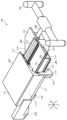
- FIG. 4 is a perspective view showing a steering device holding a steering member;
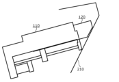
- FIG. 4 is a side view showing the steering device in a reversed state;
- FIG. 4 is a side view showing the steering device in the advanced state and the foot of the driver;
- FIG. 2 is a perspective view showing a steering device with a fixing member omitted;
- FIG. 4 is a side view showing a movable guide portion, rolling elements, and a retainer together with a movable member;
- FIG. 4 is a side view showing a state of torque generation;
- drawings are schematic diagrams that have been appropriately emphasized, omitted, or adjusted in proportion in order to explain the present invention, and differ from the actual shape, positional relationship, and proportion.
- the X-axis, Y-axis, and Z-axis that may be shown in the drawing indicate orthogonal coordinates that are arbitrarily set for explanation of the drawing.
- the Z-axis is not necessarily the axis along the vertical direction
- the X-axis and the Y-axis are not necessarily in the horizontal plane.
- FIG. 1 is a perspective view showing a steering device holding a steering member.
- the steering device 100 is a steering device 100 that holds a steering member 200 movably between an advanced position where the driver can steer and a backward position that is the front side of the vehicle.
- a member 120 , an upper guide mechanism 130 and a lower guide mechanism 140 are provided.
- the fixed member 110 is a member that is fixedly attached to a reinforcement, which is one of the structural members provided on the vehicle body.
- the manner in which the fixing member 110 is attached to the vehicle body is not limited, but in the case of the present embodiment, the fixing member 110 is attached in a state of being suspended from reinforcement stretched across the width direction of the vehicle body.
- the cross-sectional shape of the fixed member 110 perpendicular to the moving direction of the movable member 120 (the Y-axis direction in the drawing) is an L-shape rotated 90 degrees to the right. and a fixed wall portion 112 extending in a drooping manner on one side (X ⁇ side in the drawing) of the fixed top plate portion 111 in the direction (the X-axis direction in the drawing).
- a moving device 115 for moving the movable member 120 is attached below the fixed member 110 (Z- side in the figure).
- the type of the moving device 115 is not particularly limited, but in the case of the present embodiment, the movable member 120 is attached via the fixed bracket 116 so as to extend in the moving direction of the movable member 120 (the Y-axis direction in the drawing). 120, a movable nut 128 that meshes with the feed screw 117 and reciprocates in the moving direction of the movable member 120 by the rotation of the feed screw 117, and a motor that rotates the feed screw 117. and a drive device 118 .
- the movable member 120 is a member attached to the fixed member 110 by the upper guide mechanism 130, the lower guide mechanism 140, and the moving device 115 so as to be able to reciprocate between an advanced position and a retracted position.
- a steering shaft 150 that holds the steering member 200 is rotatably attached to the movable member 120 .
- the cross-sectional shape perpendicular to the movement direction (the Y-axis direction in the drawing) of the movable member 120 is an L-shape rotated 90 degrees to the right.
- the movable wall portion 122 is thicker than the fixed wall portion 112 in the width direction, and is provided with a through hole 125 through which a harness or the like connected to an operation switch or the like is inserted.
- the movable top plate portion 121 is provided with a notch portion 129 on the front side of the vehicle (the Y+ side in the figure) of the steering shaft body 150 .
- the cutout portion 129 in the movable top plate portion 121 the movable member 120 in the retracted position can be prevented from interfering with a part of the brake mechanism, the air conditioner, the tire house, etc., and the retracted position is arranged in front of the vehicle. It becomes possible to
- the position of the end of the advancing side (Y ⁇ side in the figure) of the movable top plate portion 121, which is the upper portion to which the upper guide mechanism 130 of the movable member 120 is attached, is the position where the lower guide mechanism 140 of the movable member 120 is attached. It is positioned on the advance side of the position of the end on the advance side of the lower portion of the movable wall portion 122, which is the lower portion.
- the advancing-side end of the movable wall portion 122 is inclined so as to protrude toward the advancing side as it goes upward, and the advancing-side end of the movable wall portion 122 is lower than the lower portion.
- the upper portion is located on the advancing side.
- the movable member 120 can be accommodated without protruding inside. Also, the length of the upper side of the movable wall portion 122 of the movable member 120 can be increased according to the inclination of the vehicle member 210 . As a result, the upper guide mechanism 130, which will be described later, can be arranged on the advance side of the lower guide mechanism 140. As shown in FIG. Further, as shown in FIG. 3, when the movable member 120 is arranged at the advanced position, even if the driver's knee 300 moves to the front side of the vehicle at the time of a vehicle collision, the protruding movable member 120 and the knee will not move. 300 can be avoided.
- FIG. 4 is a perspective view showing the steering device 100 with the fixing member omitted.
- the upper guide mechanism 130 is a mechanism that linearly guides the movable member 120 in the advance and retreat direction with respect to the fixed member 110 .
- the upper guide mechanism 130 includes an upper fixed guide portion 131 fixed inside the fixed wall portion 112 of the fixed member 110 and an upper movable guide portion 131 fixed outside the movable wall portion 122 of the movable member 120 .
- a guide portion 132 is provided.
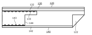
- the upper movable guide portion 132 may slide with respect to the upper fixed guide portion 131, but in this embodiment, between the upper fixed guide portion 131 and the upper movable guide portion 132, as shown in FIG. , an upper rolling element 133 which is held rollably is arranged.
- the upper fixed guide part 131 is fixedly attached to the inside of the fixed wall part 112 in the width direction (the X+ side in the drawing) while extending in the movement direction of the movable member 120 .
- the first rail 113 having the same function as the upper fixed guide portion 131 also extends on the lower surface (the Z-side surface in the figure) of the fixed top plate portion 111 in the moving direction of the movable member 120. fixedly mounted. In the advancing/retreating direction of the movable member 120 , the advancing-side end of the upper fixed guide portion 131 is located at the same position as the advancing-side end of the first rail 113 .
- the upper movable guide part 132 is fixedly attached to the outside of the movable wall part 122 in the width direction (the X ⁇ side in the figure) while extending in the moving direction of the movable member 120 .
- a second rail 123 having the same function as the upper movable guide portion 132 is also fixedly mounted on the upper surface (Z+ side surface in the figure) of the movable top plate portion 121 while extending in the movement direction. installed.
- the position of the advancing side end of the upper movable guide portion 132 is arranged at the same position as the position of the advancing side end of the second rail.
- the first rail 113 and the second rail 123 are connected so as to be linearly movable via two rows of balls held by a retainer, similarly to the upper guide mechanism 130 in the present embodiment.
- the lower guide mechanism 140 is arranged parallel to the upper guide mechanism 130 on the lower side of the upper guide mechanism 130 (the Z ⁇ side in the drawing), and is a mechanism that linearly guides the movable member 120 with respect to the fixed member 110 in the advancing/retreating direction. is.
- the lower guide mechanism 140 includes a lower fixed guide portion 141 fixed inside the fixed wall portion 112 of the fixed member 110 and fixed outside the movable wall portion 122 of the movable member 120. and a lower movable guide portion 142 .
- the lower movable guide portion 142 may slide with respect to the lower fixed guide portion 141, but in the present embodiment, between the lower fixed guide portion 141 and the lower movable guide portion 142, there is a gap as shown in FIG. 2, a lower rolling element 143 is arranged so as to be rollably held so as to maintain a predetermined spacing.
- the lower fixed guide portion 141 is arranged in parallel with the upper fixed guide portion 131, and extends in the moving direction of the movable member 120 inside the fixed wall portion 112 in the width direction (X+ side in the drawing). attached to the
- the lower movable guide portion 142 is arranged parallel to the upper movable guide portion 132, and is fixed to the outside of the movable wall portion 122 in the width direction (the X ⁇ side in the figure) while extending in the moving direction of the movable member 120. properly attached.
- the fixed member 110 is arranged so that the end of the upper fixed guide portion 131 on the advancing side is arranged on the advancing side relative to the end of the lower fixed guide portion 141 on the advancing side in the advancing/retreating direction of the movable member 120 .
- the upper movable guide portion 132 is attached to the movable member 120 so that the advance side end of the upper movable guide portion 132 is arranged on the advance side of the advance side end of the lower movable guide portion 142 .
- the length of the upper movable guide portion 132 is longer than the length of the lower movable guide portion.
- the number of upper rolling elements 133 is greater than the number of lower rolling elements 143 .
- the upper fixed guide portion 131 and the lower fixed guide portion 141 are formed integrally by bending sheet metal.
- the upper movable guide portion 132 and the lower movable guide portion 142 are integrally formed by bending sheet metal.
- the upper rolling element 133 and the lower rolling element 143 are rotatably held by a single trapezoidal retainer 144 whose upper base is longer than its lower base.
- the steering shaft 150 is a member that is attached to the movable member 120 and holds the steering member 200 rotatably.
- the shape of the steering shaft body 150 is not particularly limited, and examples thereof include a columnar shape and a hexagonal columnar shape.
- the steering shaft body 150 may have a cross-sectional shape and a cross-sectional area that change in the axial direction.
- the steering shaft body 150 is attached to the movable member 120 so as to be rotatable about its axis.
- a sensor such as a steering angle sensor is attached to the end of the steering shaft 150 on the driver's side (the Y- side in the drawing).
- the rotation angle of the steering shaft 150 that is, the steering angle of the steering member 200 is detected by a steering angle sensor (not shown), and the steerable wheels are steered based on the signal from the steering angle sensor. be.
- the torque T generated when the driver applies a downward force to the steering member 200 arranged in the advanced position is set to a distance longer than the arrangement length of the plurality of lower rolling elements 143 arranged in a line. It can be supported in at least two places (for example, between point A and point B). As a result, the structural strength of the steering device 100 can be improved, and the driver holding the steering member 200 can feel a sense of stability and security.
- the number of upper rolling elements 133 is greater than the number of lower rolling elements 143, that is, the contact length between the upper fixed guide portion 131 and the upper movable guide portion 132 (via the rolling elements) is Since the guide portion 141 and the lower movable guide portion 142 are longer than the length of contact (via the rolling element), it occurs when the driver applies downward force to the steering member 200 arranged at the advanced position. Torque can be effectively supported. Thereby, the structural strength of the steering device 100 can be further improved.
- the present invention is not limited to the above embodiments.
- another embodiment realized by arbitrarily combining the constituent elements described in this specification or omitting some of the constituent elements may be an embodiment of the present invention.
- the present invention also includes modifications obtained by making various modifications to the above-described embodiment within the scope of the gist of the present invention, that is, the meaning of the words described in the claims, which a person skilled in the art can think of. be
- the steering device 100 may include a tilt mechanism that tilts the moving direction of the movable member 120 .
- the fixed member 110 may be swingably attached to the vehicle body, or the movable member 120 may be swingably attached to the fixed member 110 .
- the steering Another upper guide mechanism 130 and lower guide mechanism 140 may be provided on the opposite side of the shaft 150 from the upper guide mechanism 130 and the lower guide mechanism 140 .
- the present invention can be used for steering devices for steering vehicles such as automobiles, buses, and trucks, linkless steering devices, and the like.
Landscapes
- Engineering & Computer Science (AREA)
- General Engineering & Computer Science (AREA)
- Mechanical Engineering (AREA)
- Chemical & Material Sciences (AREA)
- Combustion & Propulsion (AREA)
- Transportation (AREA)
- Platform Screen Doors And Railroad Systems (AREA)
- Steering Controls (AREA)
- Body Structure For Vehicles (AREA)
Priority Applications (5)
| Application Number | Priority Date | Filing Date | Title |
|---|---|---|---|
| US18/727,243 US12286147B2 (en) | 2022-02-02 | 2022-02-02 | Steering device |
| CN202280090225.3A CN118613415A (zh) | 2022-02-02 | 2022-02-02 | 转向装置 |
| PCT/JP2022/004098 WO2023148855A1 (ja) | 2022-02-02 | 2022-02-02 | ステアリング装置 |
| JP2023578250A JP7729411B2 (ja) | 2022-02-02 | 2022-02-02 | ステアリング装置 |
| EP22924595.6A EP4474244A4 (en) | 2022-02-02 | 2022-02-02 | STEERING DEVICE |
Applications Claiming Priority (1)
| Application Number | Priority Date | Filing Date | Title |
|---|---|---|---|
| PCT/JP2022/004098 WO2023148855A1 (ja) | 2022-02-02 | 2022-02-02 | ステアリング装置 |
Publications (1)
| Publication Number | Publication Date |
|---|---|
| WO2023148855A1 true WO2023148855A1 (ja) | 2023-08-10 |
Family
ID=87553388
Family Applications (1)
| Application Number | Title | Priority Date | Filing Date |
|---|---|---|---|
| PCT/JP2022/004098 Ceased WO2023148855A1 (ja) | 2022-02-02 | 2022-02-02 | ステアリング装置 |
Country Status (5)
| Country | Link |
|---|---|
| US (1) | US12286147B2 (https=) |
| EP (1) | EP4474244A4 (https=) |
| JP (1) | JP7729411B2 (https=) |
| CN (1) | CN118613415A (https=) |
| WO (1) | WO2023148855A1 (https=) |
Cited By (1)
| Publication number | Priority date | Publication date | Assignee | Title |
|---|---|---|---|---|
| US12371092B2 (en) * | 2021-12-20 | 2025-07-29 | Jtekt Corporation | Steering device |
Citations (5)
| Publication number | Priority date | Publication date | Assignee | Title |
|---|---|---|---|---|
| US3977692A (en) * | 1975-03-20 | 1976-08-31 | The Scott & Fetzer Company | Extensible support structure |
| WO2019005736A1 (en) | 2017-06-26 | 2019-01-03 | Nio Usa, Inc. | SLIDING STEERING COLUMN MOUNTED ON A BODY AND COMPRISING A DECALED FEEDBACK ACTUATOR |
| WO2019193956A1 (ja) | 2018-04-04 | 2019-10-10 | 株式会社ジェイテクト | ステアリング装置 |
| JP2020185851A (ja) * | 2019-05-13 | 2020-11-19 | 株式会社ジェイテクト | ステアリング装置 |
| JP2021020583A (ja) * | 2019-07-29 | 2021-02-18 | 株式会社ジェイテクト | ステアリング装置 |
Family Cites Families (6)
| Publication number | Priority date | Publication date | Assignee | Title |
|---|---|---|---|---|
| FR2841524B1 (fr) | 2002-06-27 | 2005-12-16 | Nacam | Dispositif d'absorption d'energie d'une colonne de direction de vehicule automobile |
| DE102005022408A1 (de) * | 2005-05-14 | 2006-11-16 | Zf Lenksysteme Gmbh | Anordnung einer Lenksäule |
| KR101953140B1 (ko) * | 2017-01-26 | 2019-03-05 | 주식회사 만도 | 차량의 조향컬럼 |
| US10457314B2 (en) | 2017-06-26 | 2019-10-29 | Nio Usa, Inc. | Retractable telescopic mechanism for steering column with feedback actuator |
| JP7374406B2 (ja) * | 2019-09-17 | 2023-11-07 | 株式会社アイシン | 車両のステアリング装置 |
| KR102368822B1 (ko) * | 2020-06-30 | 2022-03-03 | 남양넥스모 주식회사 | 레일 스토어블 전동 컬럼 |
-
2022
- 2022-02-02 EP EP22924595.6A patent/EP4474244A4/en active Pending
- 2022-02-02 US US18/727,243 patent/US12286147B2/en active Active
- 2022-02-02 JP JP2023578250A patent/JP7729411B2/ja active Active
- 2022-02-02 CN CN202280090225.3A patent/CN118613415A/zh active Pending
- 2022-02-02 WO PCT/JP2022/004098 patent/WO2023148855A1/ja not_active Ceased
Patent Citations (5)
| Publication number | Priority date | Publication date | Assignee | Title |
|---|---|---|---|---|
| US3977692A (en) * | 1975-03-20 | 1976-08-31 | The Scott & Fetzer Company | Extensible support structure |
| WO2019005736A1 (en) | 2017-06-26 | 2019-01-03 | Nio Usa, Inc. | SLIDING STEERING COLUMN MOUNTED ON A BODY AND COMPRISING A DECALED FEEDBACK ACTUATOR |
| WO2019193956A1 (ja) | 2018-04-04 | 2019-10-10 | 株式会社ジェイテクト | ステアリング装置 |
| JP2020185851A (ja) * | 2019-05-13 | 2020-11-19 | 株式会社ジェイテクト | ステアリング装置 |
| JP2021020583A (ja) * | 2019-07-29 | 2021-02-18 | 株式会社ジェイテクト | ステアリング装置 |
Non-Patent Citations (1)
| Title |
|---|
| See also references of EP4474244A4 |
Cited By (1)
| Publication number | Priority date | Publication date | Assignee | Title |
|---|---|---|---|---|
| US12371092B2 (en) * | 2021-12-20 | 2025-07-29 | Jtekt Corporation | Steering device |
Also Published As
| Publication number | Publication date |
|---|---|
| US20250091635A1 (en) | 2025-03-20 |
| EP4474244A4 (en) | 2025-04-02 |
| JPWO2023148855A1 (https=) | 2023-08-10 |
| JP7729411B2 (ja) | 2025-08-26 |
| US12286147B2 (en) | 2025-04-29 |
| CN118613415A (zh) | 2024-09-06 |
| EP4474244A1 (en) | 2024-12-11 |
Similar Documents
| Publication | Publication Date | Title |
|---|---|---|
| EP3628565B1 (en) | Steering apparatus and method for controlling steering apparatus | |
| JP7380445B2 (ja) | ステアリング装置、異常判断方法、および異常判断プログラム | |
| WO2023148855A1 (ja) | ステアリング装置 | |
| US12371092B2 (en) | Steering device | |
| JP7268646B2 (ja) | 車両用ステアリング装置 | |
| WO2023119744A1 (ja) | ステアリング装置 | |
| US20250276731A1 (en) | Steering system for motor vehicle and motor vehicle comprising the same | |
| JP2018131058A (ja) | ステアリング装置 | |
| JP7790553B2 (ja) | ステアリング装置、およびステアリング装置の製造方法 | |
| US20220048554A1 (en) | Bracket and steering apparatus | |
| JP7786185B2 (ja) | ステアリング装置 | |
| JP6754431B2 (ja) | レール走行構造およびそのレール走行構造を備えた工作機械 | |
| JP2025162352A (ja) | ステアリング装置 | |
| JP6164470B2 (ja) | ステアリング装置 | |
| WO2025004208A1 (ja) | ステアリング装置 | |
| US20250242853A1 (en) | Steering system | |
| JP2006051838A (ja) | 全方向移動車 | |
| WO2023175876A1 (ja) | ステアリング装置 | |
| EP4733172A1 (en) | Steering device | |
| JP2007045276A (ja) | ステアリング装置 | |
| JP2024035550A (ja) | 回転伝達装置及び操舵装置 | |
| JP2023077175A (ja) | ステアリングコラム装置 | |
| JP2007015678A (ja) | 車両用電動位置調整式ステアリング装置 | |
| JP2009077478A (ja) | 減速機構付モータ及びこれを使用したステアリング装置 |
Legal Events
| Date | Code | Title | Description |
|---|---|---|---|
| 121 | Ep: the epo has been informed by wipo that ep was designated in this application |
Ref document number: 22924595 Country of ref document: EP Kind code of ref document: A1 |
|
| ENP | Entry into the national phase |
Ref document number: 2023578250 Country of ref document: JP Kind code of ref document: A |
|
| WWE | Wipo information: entry into national phase |
Ref document number: 18727243 Country of ref document: US |
|
| WWE | Wipo information: entry into national phase |
Ref document number: 202280090225.3 Country of ref document: CN |
|
| WWE | Wipo information: entry into national phase |
Ref document number: 2022924595 Country of ref document: EP |
|
| NENP | Non-entry into the national phase |
Ref country code: DE |
|
| ENP | Entry into the national phase |
Ref document number: 2022924595 Country of ref document: EP Effective date: 20240902 |
|
| WWP | Wipo information: published in national office |
Ref document number: 18727243 Country of ref document: US |
|
| WWG | Wipo information: grant in national office |
Ref document number: 18727243 Country of ref document: US |