WO2023148841A1 - 熱交換器および空気調和装置 - Google Patents
熱交換器および空気調和装置 Download PDFInfo
- Publication number
- WO2023148841A1 WO2023148841A1 PCT/JP2022/004016 JP2022004016W WO2023148841A1 WO 2023148841 A1 WO2023148841 A1 WO 2023148841A1 JP 2022004016 W JP2022004016 W JP 2022004016W WO 2023148841 A1 WO2023148841 A1 WO 2023148841A1
- Authority
- WO
- WIPO (PCT)
- Prior art keywords
- heat exchange
- refrigerant
- exchange section
- distributor
- heat
- Prior art date
- Legal status (The legal status is an assumption and is not a legal conclusion. Google has not performed a legal analysis and makes no representation as to the accuracy of the status listed.)
- Ceased
Links
Images








Classifications
-
- F—MECHANICAL ENGINEERING; LIGHTING; HEATING; WEAPONS; BLASTING
- F28—HEAT EXCHANGE IN GENERAL
- F28D—HEAT-EXCHANGE APPARATUS, NOT PROVIDED FOR IN ANOTHER SUBCLASS, IN WHICH THE HEAT-EXCHANGE MEDIA DO NOT COME INTO DIRECT CONTACT
- F28D1/00—Heat-exchange apparatus having stationary conduit assemblies for one heat-exchange medium only, the media being in contact with different sides of the conduit wall, in which the other heat-exchange medium is a large body of fluid, e.g. domestic or motor car radiators
- F28D1/02—Heat-exchange apparatus having stationary conduit assemblies for one heat-exchange medium only, the media being in contact with different sides of the conduit wall, in which the other heat-exchange medium is a large body of fluid, e.g. domestic or motor car radiators with heat-exchange conduits immersed in the body of fluid
- F28D1/04—Heat-exchange apparatus having stationary conduit assemblies for one heat-exchange medium only, the media being in contact with different sides of the conduit wall, in which the other heat-exchange medium is a large body of fluid, e.g. domestic or motor car radiators with heat-exchange conduits immersed in the body of fluid with tubular conduits
- F28D1/053—Heat-exchange apparatus having stationary conduit assemblies for one heat-exchange medium only, the media being in contact with different sides of the conduit wall, in which the other heat-exchange medium is a large body of fluid, e.g. domestic or motor car radiators with heat-exchange conduits immersed in the body of fluid with tubular conduits the conduits being straight
- F28D1/0535—Heat-exchange apparatus having stationary conduit assemblies for one heat-exchange medium only, the media being in contact with different sides of the conduit wall, in which the other heat-exchange medium is a large body of fluid, e.g. domestic or motor car radiators with heat-exchange conduits immersed in the body of fluid with tubular conduits the conduits being straight the conduits having a non-circular cross-section
- F28D1/05366—Assemblies of conduits connected to common headers, e.g. core type radiators
- F28D1/05383—Assemblies of conduits connected to common headers, e.g. core type radiators with multiple rows of conduits or with multi-channel conduits
-
- F—MECHANICAL ENGINEERING; LIGHTING; HEATING; WEAPONS; BLASTING
- F28—HEAT EXCHANGE IN GENERAL
- F28F—DETAILS OF HEAT-EXCHANGE AND HEAT-TRANSFER APPARATUS, OF GENERAL APPLICATION
- F28F9/00—Casings; Header boxes; Auxiliary supports for elements; Auxiliary members within casings
- F28F9/02—Header boxes; End plates
- F28F9/0246—Arrangements for connecting header boxes with flow lines
-
- F—MECHANICAL ENGINEERING; LIGHTING; HEATING; WEAPONS; BLASTING
- F25—REFRIGERATION OR COOLING; COMBINED HEATING AND REFRIGERATION SYSTEMS; HEAT PUMP SYSTEMS; MANUFACTURE OR STORAGE OF ICE; LIQUEFACTION SOLIDIFICATION OF GASES
- F25B—REFRIGERATION MACHINES, PLANTS OR SYSTEMS; COMBINED HEATING AND REFRIGERATION SYSTEMS; HEAT PUMP SYSTEMS
- F25B13/00—Compression machines, plants or systems, with reversible cycle
-
- F—MECHANICAL ENGINEERING; LIGHTING; HEATING; WEAPONS; BLASTING
- F25—REFRIGERATION OR COOLING; COMBINED HEATING AND REFRIGERATION SYSTEMS; HEAT PUMP SYSTEMS; MANUFACTURE OR STORAGE OF ICE; LIQUEFACTION SOLIDIFICATION OF GASES
- F25B—REFRIGERATION MACHINES, PLANTS OR SYSTEMS; COMBINED HEATING AND REFRIGERATION SYSTEMS; HEAT PUMP SYSTEMS
- F25B39/00—Evaporators; Condensers
-
- F—MECHANICAL ENGINEERING; LIGHTING; HEATING; WEAPONS; BLASTING
- F25—REFRIGERATION OR COOLING; COMBINED HEATING AND REFRIGERATION SYSTEMS; HEAT PUMP SYSTEMS; MANUFACTURE OR STORAGE OF ICE; LIQUEFACTION SOLIDIFICATION OF GASES
- F25B—REFRIGERATION MACHINES, PLANTS OR SYSTEMS; COMBINED HEATING AND REFRIGERATION SYSTEMS; HEAT PUMP SYSTEMS
- F25B41/00—Fluid-circulation arrangements
- F25B41/40—Fluid line arrangements
- F25B41/42—Arrangements for diverging or converging flows, e.g. branch lines or junctions
-
- F—MECHANICAL ENGINEERING; LIGHTING; HEATING; WEAPONS; BLASTING
- F28—HEAT EXCHANGE IN GENERAL
- F28D—HEAT-EXCHANGE APPARATUS, NOT PROVIDED FOR IN ANOTHER SUBCLASS, IN WHICH THE HEAT-EXCHANGE MEDIA DO NOT COME INTO DIRECT CONTACT
- F28D1/00—Heat-exchange apparatus having stationary conduit assemblies for one heat-exchange medium only, the media being in contact with different sides of the conduit wall, in which the other heat-exchange medium is a large body of fluid, e.g. domestic or motor car radiators
- F28D1/02—Heat-exchange apparatus having stationary conduit assemblies for one heat-exchange medium only, the media being in contact with different sides of the conduit wall, in which the other heat-exchange medium is a large body of fluid, e.g. domestic or motor car radiators with heat-exchange conduits immersed in the body of fluid
- F28D1/04—Heat-exchange apparatus having stationary conduit assemblies for one heat-exchange medium only, the media being in contact with different sides of the conduit wall, in which the other heat-exchange medium is a large body of fluid, e.g. domestic or motor car radiators with heat-exchange conduits immersed in the body of fluid with tubular conduits
- F28D1/053—Heat-exchange apparatus having stationary conduit assemblies for one heat-exchange medium only, the media being in contact with different sides of the conduit wall, in which the other heat-exchange medium is a large body of fluid, e.g. domestic or motor car radiators with heat-exchange conduits immersed in the body of fluid with tubular conduits the conduits being straight
- F28D1/0535—Heat-exchange apparatus having stationary conduit assemblies for one heat-exchange medium only, the media being in contact with different sides of the conduit wall, in which the other heat-exchange medium is a large body of fluid, e.g. domestic or motor car radiators with heat-exchange conduits immersed in the body of fluid with tubular conduits the conduits being straight the conduits having a non-circular cross-section
- F28D1/05366—Assemblies of conduits connected to common headers, e.g. core type radiators
- F28D1/05391—Assemblies of conduits connected to common headers, e.g. core type radiators with multiple rows of conduits or with multi-channel conduits combined with a particular flow pattern, e.g. multi-row multi-stage radiators
-
- F—MECHANICAL ENGINEERING; LIGHTING; HEATING; WEAPONS; BLASTING
- F28—HEAT EXCHANGE IN GENERAL
- F28F—DETAILS OF HEAT-EXCHANGE AND HEAT-TRANSFER APPARATUS, OF GENERAL APPLICATION
- F28F9/00—Casings; Header boxes; Auxiliary supports for elements; Auxiliary members within casings
- F28F9/02—Header boxes; End plates
- F28F9/026—Header boxes; End plates with static flow control means, e.g. with means for uniformly distributing heat exchange media into conduits
- F28F9/027—Header boxes; End plates with static flow control means, e.g. with means for uniformly distributing heat exchange media into conduits in the form of distribution pipes
- F28F9/0275—Header boxes; End plates with static flow control means, e.g. with means for uniformly distributing heat exchange media into conduits in the form of distribution pipes with multiple branch pipes
-
- F—MECHANICAL ENGINEERING; LIGHTING; HEATING; WEAPONS; BLASTING
- F28—HEAT EXCHANGE IN GENERAL
- F28F—DETAILS OF HEAT-EXCHANGE AND HEAT-TRANSFER APPARATUS, OF GENERAL APPLICATION
- F28F9/00—Casings; Header boxes; Auxiliary supports for elements; Auxiliary members within casings
- F28F9/02—Header boxes; End plates
- F28F9/026—Header boxes; End plates with static flow control means, e.g. with means for uniformly distributing heat exchange media into conduits
- F28F9/0278—Header boxes; End plates with static flow control means, e.g. with means for uniformly distributing heat exchange media into conduits in the form of stacked distribution plates or perforated plates arranged over end plates
-
- F—MECHANICAL ENGINEERING; LIGHTING; HEATING; WEAPONS; BLASTING
- F28—HEAT EXCHANGE IN GENERAL
- F28D—HEAT-EXCHANGE APPARATUS, NOT PROVIDED FOR IN ANOTHER SUBCLASS, IN WHICH THE HEAT-EXCHANGE MEDIA DO NOT COME INTO DIRECT CONTACT
- F28D21/00—Heat-exchange apparatus not covered by any of the groups F28D1/00 - F28D20/00
- F28D2021/0019—Other heat exchangers for particular applications; Heat exchange systems not otherwise provided for
- F28D2021/0068—Other heat exchangers for particular applications; Heat exchange systems not otherwise provided for for refrigerant cycles
-
- F—MECHANICAL ENGINEERING; LIGHTING; HEATING; WEAPONS; BLASTING
- F28—HEAT EXCHANGE IN GENERAL
- F28F—DETAILS OF HEAT-EXCHANGE AND HEAT-TRANSFER APPARATUS, OF GENERAL APPLICATION
- F28F1/00—Tubular elements; Assemblies of tubular elements
- F28F1/10—Tubular elements and assemblies thereof with means for increasing heat-transfer area, e.g. with fins, with projections, with recesses
- F28F1/12—Tubular elements and assemblies thereof with means for increasing heat-transfer area, e.g. with fins, with projections, with recesses the means being only outside the tubular element
- F28F1/24—Tubular elements and assemblies thereof with means for increasing heat-transfer area, e.g. with fins, with projections, with recesses the means being only outside the tubular element and extending transversely
- F28F1/32—Tubular elements and assemblies thereof with means for increasing heat-transfer area, e.g. with fins, with projections, with recesses the means being only outside the tubular element and extending transversely the means having portions engaging further tubular elements
-
- F—MECHANICAL ENGINEERING; LIGHTING; HEATING; WEAPONS; BLASTING
- F28—HEAT EXCHANGE IN GENERAL
- F28F—DETAILS OF HEAT-EXCHANGE AND HEAT-TRANSFER APPARATUS, OF GENERAL APPLICATION
- F28F9/00—Casings; Header boxes; Auxiliary supports for elements; Auxiliary members within casings
- F28F9/22—Arrangements for directing heat-exchange media into successive compartments, e.g. arrangements of guide plates
- F28F2009/222—Particular guide plates, baffles or deflectors, e.g. having particular orientation relative to an elongated casing or conduit
Definitions
- the present disclosure relates to heat exchangers and air conditioners equipped with refrigerant distributors.
- the refrigerant flowing into the communication header at this time is in a gas-liquid two-phase state, for example, due to the influence of gravity, for example, the liquid-phase refrigerant flows downward and the gas-phase refrigerant flows upward, causing a drift in the refrigerant flow. and, as a result, the refrigerant cannot be evenly distributed. If the refrigerant cannot be evenly distributed, the performance of the heat exchanger tends to deteriorate, especially during heating.
- the present disclosure has been made to solve such problems, and has an optimal number of stages that maximizes the performance of the heat exchanger while realizing even distribution of the refrigerant to the heat transfer tubes of the heat exchanger. , heat exchangers and air conditioners.
- a heat exchanger includes a plurality of fins spaced from each other in a first direction, and a plurality of fins penetrating the plurality of fins and spaced from each other in a second direction intersecting the first direction.
- a heat exchange unit that exchanges heat between a refrigerant flowing inside and air flowing around the heat exchange unit, and a heat exchange unit that has a plurality of heat transfer tubes arranged in the first direction, and at one end of the heat exchange unit in the first direction and a connected refrigerant distributor, the refrigerant distributor having a first inlet and a plurality of first outlets, wherein a portion of the plurality of heat transfer tubes are located at the first outlets.
- a distributor having a collision wall inside, and branching the refrigerant that has flowed in from the first inlet when the refrigerant collides with the collision wall, and causes the refrigerant to flow out from each of the first outlets.
- a distributor having a second inlet, and a plurality of second outlets, the other part of the plurality of heat transfer tubes being connected to the second outlet, and having a communication space inside and a communication header that branches the refrigerant that has flowed into the communication space from the second inlet and flows out from each of the second outlets, and the number of branches of the refrigerant that passes through the communication header.
- K is less than the number M of branches of the refrigerant through the distributor.
- An air conditioner is an air conditioner in which an outdoor unit and an indoor unit are pipe-connected to form a refrigerant circuit, wherein the outdoor unit includes a compressor that compresses and discharges a refrigerant; an outdoor heat exchanger that exchanges heat between outdoor air and the refrigerant; an outdoor fan that blows the outdoor air to the outdoor heat exchanger; and expands the refrigerant and an expansion valve for reducing the pressure by reducing the pressure, wherein the indoor unit includes an indoor heat exchanger that exchanges heat between indoor air and the refrigerant, and blows the indoor air to the indoor heat exchanger. and an indoor fan, wherein at least one of the outdoor heat exchanger and the outdoor heat exchanger is composed of the heat exchanger described above.
- the refrigerant distributor of the heat exchanger has a collision wall inside, and the refrigerant collides with the collision wall to distribute the refrigerant. and a communication header for distributing the refrigerant through the communication space. Also, the branch number K of the communication header is set to a value smaller than the branch number M of the distributor.
- a main method of distributing the refrigerant one or more distributors having a configuration that facilitates even distribution of the refrigerant are used. This makes it possible to evenly distribute the refrigerant throughout the heat exchanger.
- a communication header with a branch number K smaller than M is also used so as not to be hindered by the restriction of "every M stages" depending on the branch number M of the distributor.
- the number of stages of the heat exchanger can be freely selected. As a result, it is possible to realize a design with the optimum number of stages that maximizes the performance of the heat exchanger.
- FIG. 1 is a refrigerant circuit diagram showing an example of a configuration of a refrigeration cycle device that constitutes an air conditioner according to Embodiment 1.
- FIG. 1 is a configuration diagram schematically showing the configuration of a heat exchanger according to Embodiment 1;
- FIG. 1 is a perspective view showing a configuration of a heat exchanger according to Embodiment 1;
- FIG. 4 is a partially enlarged perspective view showing the configuration of a heat exchange section provided in the heat exchanger according to Embodiment 1.
- FIG. 4 is a partially enlarged side view showing the configuration of a heat exchange section provided in the heat exchanger according to Embodiment 1;
- FIG. 1 is a configuration diagram schematically showing the configuration of a heat exchanger according to Embodiment 1;
- FIG. 1 is a perspective view showing a configuration of a heat exchanger according to Embodiment 1;
- FIG. 4 is a partially enlarged perspective view showing the configuration of a heat exchange section provided in the heat exchanger according to Em
- FIG. 4 is a cross-sectional view showing an example of the configuration of a communication header provided in the heat exchanger according to Embodiment 1;
- FIG. 3 is an exploded perspective view showing an example of the configuration of a distributor provided in the heat exchanger according to Embodiment 1;
- FIG. 4 is a perspective view showing another example of the configuration of the distributor provided in the heat exchanger according to Embodiment 1.
- FIG. FIG. 9 is a cross-sectional view showing the configuration of the distributor shown in FIG. 8;
- FIG. 4 is a graph showing the relationship between the number of paths of the heat exchange section and the year-round energy consumption efficiency APF in the heat exchanger according to Embodiment 1;
- FIG. 3 is a configuration diagram showing the configuration of a heat exchanger of a comparative example;
- FIG. 5 is an explanatory diagram showing refrigerant flow rates in a communication header and heat transfer tubes under a condition where the refrigerant flow rate is low in a heat exchanger of a comparative example
- FIG. 10 is an explanatory diagram showing a refrigerant distribution state of a communication header under a condition where a refrigerant circulation flow rate is small in an air conditioner of a comparative example
- FIG. 10 is an explanatory diagram showing the distribution of refrigerant in the communication header under conditions where the refrigerant circulation flow rate is high in the air conditioner of the comparative example
- FIG. 3 is a configuration diagram showing the configuration of a heat exchanger according to a modification of Embodiment 1;
- FIG. 4 is a perspective view showing the configuration of a heat exchanger according to a modification of Embodiment 1;
- FIG. 6 is a configuration diagram schematically showing the configuration of a heat exchanger according to Embodiment 2;
- FIG. 7 is a perspective view showing the configuration of a heat exchanger according to Embodiment 2;
- FIG. 8 is a perspective view showing an example of a joint that connects heat transfer tubes of an upwind heat exchange section and a downwind heat exchange section in the heat exchanger according to Embodiment 2;
- FIG. 6 is a configuration diagram schematically showing the configuration of a heat exchanger according to Embodiment 2;
- FIG. 7 is a perspective view showing the configuration of a heat exchanger according to Embodiment 2;
- FIG. 7 is a configuration diagram schematically showing the configuration of a heat exchanger according to Embodiment 3;
- FIG. 11 is a perspective view showing the configuration of a heat exchanger according to Embodiment 3;
- FIG. 7 is a configuration diagram schematically showing the configuration of a heat exchanger according to Embodiment 3;
- FIG. 11 is a perspective view showing the configuration of a heat exchanger according to Embodiment 3;
- FIG. 11 is a configuration diagram schematically showing the configuration of a heat exchanger according to Embodiment 4;
- FIG. 11 is a perspective view showing the configuration of a heat exchanger according to Embodiment 4;
- FIG. 11 is a configuration diagram schematically showing the configuration of a heat exchanger according to Embodiment 4;
- FIG. 11 is a configuration diagram schematically showing the configuration of a heat exchanger according to Embodiment 4;
- FIG. 11 is a perspective view showing the configuration of a heat exchanger according to Embodiment 4;
- FIG. 5 is an explanatory diagram illustrating a case where refrigerant stagnation occurs in a general heat exchanger.
- FIG. 11 is a cross-sectional view showing the configuration of a communication header of a refrigerant distributor and a second refrigerant distributor provided in a heat exchanger according to Embodiment 4;
- the X direction is, for example, the horizontal direction.
- the Y direction indicates a direction intersecting the X direction and the Z direction, for example the horizontal direction.
- the X direction is sometimes called the first direction.
- the Z direction is sometimes called the second direction.
- the Y direction is sometimes called the third direction.
- FIG. 1 is a refrigerant circuit diagram showing an example of the configuration of a refrigeration cycle device that constitutes an air conditioner according to Embodiment 1.
- FIG. 1 is a refrigerant circuit diagram showing an example of the configuration of a refrigeration cycle device that constitutes an air conditioner according to Embodiment 1.
- the refrigeration cycle device that constitutes the air conditioner 1 has an outdoor unit 2 and an indoor unit 3.
- the outdoor unit 2 and the indoor unit 3 are connected via refrigerant pipes 4 .
- the outdoor unit 2 is provided with a compressor 5, a four-way valve 6, an outdoor heat exchange portion 7a, an outdoor fan 8a, an expansion valve 9, a refrigerant distributor 10a, and a gas header 11a.
- the indoor unit 3 is provided with an indoor heat exchange portion 7b, an indoor fan 8b, a refrigerant distributor 10b, and a gas header 11b.
- the refrigerant distributor 10a, the outdoor heat exchange section 7a, and the gas header 11a constitute an outdoor heat exchanger 20a.
- the refrigerant distributor 10b, the indoor heat exchange portion 7b, and the gas header 11b constitute an indoor heat exchanger 20b.
- the outdoor heat exchanger 20a and the indoor heat exchanger 20b are collectively called the heat exchanger 20 in some cases. At least one of the outdoor heat exchanger 20a and the indoor heat exchanger 20b constitutes the "heat exchanger" according to the first embodiment.
- the outdoor heat exchange section 7a and the indoor heat exchange section 7b may be collectively referred to as the heat exchange section 7.
- the outdoor fan 8a and the indoor fan 8b are collectively called the ventilation fan 8 in some cases.
- the refrigerant distributor 10a and the refrigerant distributor 10b may be collectively referred to as the refrigerant distributor 10 .
- the gas header 11a and the gas header 11b may be collectively called the gas header 11. As shown in FIG.
- the compressor 5 sucks the refrigerant flowing through the refrigerant pipe 4 .
- the compressor 5 compresses the sucked refrigerant and discharges it to the refrigerant pipe 4 .
- Compressor 5 is an inverter compressor, for example.
- the compressor 5 is an inverter compressor, the operating frequency is arbitrarily changed by an inverter circuit or the like under the control of a control device (not shown) to change the capacity of the compressor 5 to send out refrigerant per unit time. good too.
- the refrigerant discharged from the compressor 5 flows into the indoor heat exchanging portion 7b during heating, and flows into the outdoor heat exchanging portion 7a during cooling.
- the outdoor heat exchange section 7a exchanges heat between the refrigerant flowing inside the outdoor heat exchange section 7a and the air flowing around the outdoor heat exchange section 7a (that is, outdoor air).
- the outdoor heat exchange portion 7a functions as a condenser during cooling operation, and condenses and liquefies the refrigerant.
- the outdoor heat exchange portion 7a functions as an evaporator during heating operation, and evaporates the refrigerant to vaporize it.
- the indoor heat exchange section 7b exchanges heat between the refrigerant flowing inside the indoor heat exchange section 7b and the air flowing around the indoor heat exchange section 7b (that is, the indoor air to be air-conditioned).
- the indoor heat exchange portion 7b functions as an evaporator during cooling operation, and evaporates the refrigerant to vaporize it.
- the indoor heat exchange portion 7b functions as a condenser during heating operation, and condenses and liquefies the refrigerant.
- the outdoor heat exchange section 7a and the indoor heat exchange section 7b are, for example, fin-and-tube heat exchangers having heat transfer tubes and fins.
- the outdoor fan 8a has a fan motor 81a and blades 82a.
- the outdoor fan 8a blows outdoor air to the outdoor heat exchange section 7a.
- the indoor fan 8b has a fan motor 81b and a blade portion 82b.
- the indoor fan 8b blows indoor air to the indoor heat exchange portion 7b.
- the fan motor 81a and the fan motor 81b may be collectively called the fan motor 81.
- the wings 82 a and 82 b may be collectively referred to as the wings 82 .
- the four-way valve 6 is configured to switch between a cooling operation for cooling the indoor space provided with the indoor unit 3 and a heating operation for warming the indoor space.
- the four-way valve 6 is a channel switching device that switches the flow of refrigerant between cooling operation and heating operation.
- the four-way valve 6 In the case of heating operation, the four-way valve 6 is in the state indicated by the solid line in FIG. 1, and the refrigerant discharged from the compressor 5 flows into the indoor heat exchange portion 7b.
- the indoor heat exchange section 7b of the indoor unit 3 functions as a condenser, and the outdoor heat exchange section 7a of the outdoor unit 2 functions as an evaporator.
- the four-way valve 6 is in the state indicated by the dashed line in FIG. At this time, the outdoor heat exchange section 7a of the outdoor unit 2 functions as a condenser, and the indoor heat exchange section 7b of the indoor unit 3 functions as an evaporator.
- the expansion valve 9 is a decompression device that decompresses and expands the refrigerant, and is composed of, for example, an electronic expansion valve.
- the expansion valve 9 is an electronic expansion valve, the degree of opening is adjusted based on instructions from a control device (not shown) or the like.
- the expansion valve 9 is provided between the outdoor heat exchange section 7 a of the outdoor unit 2 and the indoor heat exchange section 7 b of the indoor unit 3 .
- a refrigerant distributor 10a provided in the outdoor unit 2 is connected to one end of the outdoor heat exchange section 7a.
- the refrigerant distributor 10a distributes the refrigerant to flow into the heat transfer tubes of the outdoor heat exchange section 7a when the outdoor heat exchange section 7a functions as an evaporator.
- the gas header 11a provided in the outdoor unit 2 is connected to the other end of the outdoor heat exchange section 7a.
- the gas header 11a allows the high-temperature, high-pressure gaseous refrigerant discharged from the compressor 5 to flow into the heat transfer tubes of the outdoor heat exchange section 7a when the outdoor heat exchange section 7a functions as a condenser.
- a refrigerant distributor 10b provided in the indoor unit 3 is connected to one end of the indoor heat exchange section 7b.
- the refrigerant distributor 10b distributes the refrigerant to flow into the heat transfer tubes of the indoor heat exchange portion 7b when the indoor heat exchange portion 7b functions as an evaporator.
- the gas header 11b provided in the indoor unit 3 is connected to the other end of the indoor heat exchange section 7b.
- the gas header 11b allows the high-temperature, high-pressure gaseous refrigerant discharged from the compressor 5 to flow into the heat transfer tubes of the indoor heat exchange section 7b when the indoor heat exchange section 7b functions as a condenser.
- Compressor 5 four-way valve 6, gas header 11b, indoor heat exchange portion 7b, refrigerant distributor 10b, expansion valve 9, refrigerant distributor 10a, outdoor heat exchange portion 7a, and gas header 11a are connected by refrigerant pipes 4. , constitute a refrigerant circuit.
- the high-pressure, high-temperature gaseous refrigerant discharged from the compressor 5 flows through the four-way valve 6 from the gas header 11b into the indoor heat exchange section 7b. be done.
- the refrigerant is condensed by exchanging heat with indoor air supplied by the indoor fan 8b.
- the condensed refrigerant becomes a high-pressure liquid state and flows out from the indoor heat exchange section 7b through the refrigerant distributor 10b.
- the refrigerant is decompressed by the expansion valve 9 and becomes a low-pressure gas-liquid two-phase state.
- the low-pressure gas-liquid two-phase refrigerant flows into the outdoor heat exchange section 7a via the refrigerant distributor 10a.
- the refrigerant evaporates by exchanging heat with the outdoor air supplied by the outdoor fan 8a.
- the evaporated refrigerant becomes a low-pressure gas state and is sucked into the compressor 5 .
- the refrigerant flows in the direction opposite to that in heating operation. That is, when the air conditioner 1 is in cooling operation, the high-pressure, high-temperature gaseous refrigerant discharged from the compressor 5 flows through the four-way valve 6 from the gas header 11a into the outdoor heat exchange section 7a. In the outdoor heat exchange portion 7a, the refrigerant is condensed by exchanging heat with the outdoor air supplied by the outdoor fan 8a. The condensed refrigerant becomes a high-pressure liquid state and flows out from the outdoor heat exchange section 7a through the refrigerant distributor 10a. Then, the refrigerant is decompressed by the expansion valve 9 and becomes a low-pressure gas-liquid two-phase state.
- the low-pressure gas-liquid two-phase refrigerant flows into the indoor heat exchange section 7b via the refrigerant distributor 10b.
- the refrigerant evaporates by exchanging heat with indoor air supplied by the indoor fan 8b.
- the evaporated refrigerant becomes a low-pressure gas state and is sucked into the compressor 5 .
- FIG. 2 is a configuration diagram schematically showing the configuration of the heat exchanger according to Embodiment 1.
- FIG. 3 is a perspective view showing the configuration of the heat exchanger according to Embodiment 1.
- FIG. 4 is a partially enlarged perspective view showing the configuration of the heat exchange section provided in the heat exchanger according to Embodiment 1.
- FIG. 5 is a partially enlarged side view showing the configuration of the heat exchange section provided in the heat exchanger according to Embodiment 1.
- the heat exchanger 20 is composed of a heat exchanging section 7 and a refrigerant distributor 10 connected to one end of the heat exchanging section 7 .
- the heat exchanger 20 further has a gas header 11 .
- the gas header 11 is connected to the other end of the heat exchange section 7 .
- the arrows in FIG. 2 indicate the direction in which the refrigerant flows when the heat exchange section 7 functions as an evaporator. That is, when the heat exchange section 7 functions as an evaporator, refrigerant flows from the refrigerant distributor 10 into the heat exchange section 7 and flows out toward the compressor 5 (see FIG. 1) via the gas header 11 .
- the refrigerant flows in the opposite direction when the heat exchange portion 7 functions as a condenser. That is, when the heat exchange section 7 functions as a condenser, the refrigerant flows from the gas header 11 into each heat transfer tube 70 of the heat exchange section 7, joins at the refrigerant distributor 10, and flows into the expansion valve 9 (see FIG. 1). It is discharged towards.
- the heat exchange section 7 has a plurality of fins 71 spaced apart from each other in the X direction, and heat transfer tubes 70 passing through the fins 71 .
- the heat transfer tubes 70 are spaced apart from each other in the Z direction that intersects with the X direction. That is, the heat transfer tube 70 extends in the X direction. Also, the heat transfer tubes 70 are joined to the fins 71 .
- the heat transfer tube 70 is composed of, for example, a flat tube.
- the heat transfer tubes 70 are not limited to flat tubes, and may be thin tube heat transfer tubes having an inner diameter smaller than that of ordinary heat transfer tubes.
- the heat transfer tube 70 When the heat transfer tube 70 is a flat tube, as shown in FIG. 5, the heat transfer tube 70 has a flat shape with a major axis and a minor axis. The short axis of the heat transfer tube 70 extends in the Z direction, and the long axis of the heat transfer tube 70 extends in the Y direction.
- the heat transfer tube 70 By making the heat transfer tube 70 flat, it is possible to make the outer circumference of the heat transfer tube per section longer than that of a circular tube. In this case, the diameter of the circular tube is the same length as the short diameter of the flat tube.
- the heat transfer tube 70 is formed to have a longer outer circumference than the circular tube. Accordingly, the heat transfer area of the heat transfer tube 70 is larger than that of the circular tube.
- FIG. 5 shows the case where the heat transfer tubes 70 are composed of flat perforated tubes among flat tubes.
- the inside of the heat transfer tube 70 is sectioned by the inner pillars 72 to form a plurality of small-diameter refrigerant flow paths 73 .
- a circular tube has a configuration in which only one coolant channel having a large diameter is provided.
- the heat transfer tube 70 shown in FIG. 5 can more than double the length of contact between the refrigerant and the inside of the tube in one cross section due to the subdivision, as compared with a flat tube that is not subdivided. Thereby, the heat transfer area inside the heat transfer tube 70 can be increased. As a result, heat exchange efficiency is further improved.
- the use of thin heat transfer tubes can reduce the amount of refrigerant and improve the performance of the heat exchange section 7 .
- the flat tube has a small hydraulic diameter, it is necessary to increase the number of branches in order to reduce the pressure loss of the refrigerant. If the number of branches is increased, it becomes difficult to evenly distribute the refrigerant to each heat transfer tube 70 when the heat exchange section 7 functions as an evaporator. Therefore, in Embodiment 1, in order to distribute the refrigerant evenly to each heat transfer tube 70 and realize the optimum number of stages of the heat exchange section 7, a refrigerant distributor that combines two types of distributors with different configurations 10 is used. A detailed description will be given below.
- the refrigerant distributor 10 is connected to one end of the heat exchange section 7 in the X direction.
- the one end of the heat exchanging portion 7 in the X direction is sometimes called a first end.
- the other end of the heat exchanging portion 7 in the X direction is sometimes called a second end.
- a gas header 11 is connected to the second end of the heat exchange section 7 .
- the refrigerant distributor 10 has one or more distributors 10-1 and one communication header 10-2.
- FIG. 2 shows an example in which the refrigerant distributor 10 has N distributors 10-1 and one communication header 10-2.
- the number of distributors 10-1 may be any number of one or more, and may be appropriately set as required.
- N is any integer greater than or equal to 1.
- N distributors 10-1 and one communication header 10-2 are arranged side by side in the Z direction. Assuming that the Z direction is the vertical direction, the communication header 10-2 is arranged below the distributor 10-1. Further, if the number of branches of each distributor 10-1 is M, a part of the plurality of heat transfer tubes 70 included in the heat exchange section 7 (that is, the heat transfer tubes 70 of the total number of (N ⁇ M) are connected. On the other hand, another part (K pieces) of the plurality of heat transfer tubes 70 included in the heat exchange section 7 is connected to the communication header 10-2.
- the number of branches of the distributor 10-1 is M in all. In Embodiment 1, the case where M is 8 will be described as an example, but it is not limited to this. M may be an integer of 2 or greater. However, M is a power of two. Thus, since each of the N distributors 10-1 has M branches, the number of heat transfer tubes 70 connected to all the distributors 10-1 is N ⁇ M as described above. becomes. On the other hand, the number of branches of the communication header 10-2 is K. Therefore, the number of heat transfer tubes 70 connected to the communication header is K. The total number of heat transfer tubes 70 in the heat exchange section 7 is N ⁇ M+K.
- the total number of heat transfer tubes 70 in the heat exchange section 7 is sometimes referred to as the number of paths of the heat exchange section 7 or the number of stages of the heat exchange section 7 .
- K is set to a value smaller than M in the first embodiment. That is, when M is 8, K is any integer from 1 to 7. A detailed description will be given below.
- FIG. 6 is a cross-sectional view showing an example of the configuration of a communication header provided in the heat exchanger according to Embodiment 1.
- FIG. The communication header 10-2 as shown in FIG. 3, has a bottomed cylindrical shape extending in the Z direction.
- the communication header 10-2 has closed upper and lower ends. Further, as shown in FIG. 6, the communication header 10-2 has one first opening 100 and a plurality of second openings 101 on its side surface. The first opening 100 and the second opening 101 face each other.
- the number of second openings 101 is the number of branches of the communication header 10-2. In the example of FIG. 2, the case where the number of branches is K is shown. Therefore, the number of second openings 101 is K.
- the K second openings 101 of the communication header 10-2 are connected to the K heat transfer tubes 70 out of the plurality of heat transfer tubes 70 of the heat exchange section 7. As shown in FIG.
- the second opening 101 functions as a heat transfer tube insertion space.
- the communication header 10-2 has a communication space 102 inside, as shown in FIG.
- the communication space 102 extends in the Z direction.
- the communication space 102 communicates with the first openings 100 and all the second openings 101 .
- the refrigerant that has flowed into the communication space 102 from the first openings 100 flows out from each of the K second openings 101 to the heat transfer tubes 70 of the heat exchange section 7 .
- the communication header 10-2 functions as a distributor that branches the refrigerant that has flowed into the interior into K pieces and causes them to flow out to the heat transfer tubes 70 of the heat exchange section 7.
- the gas header 11 has the same configuration as the communication header 10-2 shown in FIG. That is, the gas header 11 has a bottomed tubular shape extending in the Z direction. The gas header 11 is closed at its upper and lower ends. Also, the gas header 11 has one first opening and a plurality of second openings on its side surface. The gas header has a communication space inside. The communication space extends in the Z direction. The communication space communicates with the first openings and with all the second openings. The refrigerant that has flowed into the communication space from the first openings flows out from each of the second openings 101 to the connecting pipes connected to the gas header 11 .
- FIG. 7 is an exploded perspective view showing an example of the configuration of a distributor provided in the heat exchanger according to Embodiment 1.
- the distributor 10-1 includes, for example, one first opening 103, a plurality of second openings 104, and a distribution channel 105 connecting the first openings 103 and the second openings 104. , and a stacked header.
- the distributor 10-1 is a two-branch type distributor with the number of branches being a power of two.
- the case where the distributor 10-1 repeats 2-branching 3 times is taken as an example, but it is not limited to that case, and 2 to the power of X may be used.
- X is any integer greater than or equal to 1.
- the distributor 10-1 has a first plate member 106, a second plate member 107, and a third plate member .
- the first plate-like member 106, the second plate-like member 107, and the third plate-like member 108 have basically the same shape and size in their plate-like peripheries. , each of which has a vertically long rectangular plate shape. Therefore, the longitudinal direction of the first plate member 106, the second plate member 107, and the third plate member 108 is the Z direction.
- the distributor 10-1 is formed by laminating one or more plate-like members each having a channel for branching the refrigerant into two.
- the distributor 10-1 includes a communication wall 109 arranged between the first plate-like member 106 and the second plate-like member 107, the second plate-like member 107 and the third plate-like member 107. and a collision wall 110 disposed between the plate member 108 and the plate member 108 .
- the communication wall 109 and the collision wall 110 have a vertically long rectangular plate shape, as shown in FIG.
- the communication wall 109 and the collision wall 110 have basically the same plate-like outer periphery as the first plate-like member 106, the second plate-like member 107, and the third plate-like member 108. It has shape and size. Therefore, the longitudinal direction of the first plate member 106, the second plate member 107, and the third plate member 108 is the Z direction.
- the laminated header that constitutes the distributor 10-1 includes a first plate-like member 106, a communication wall 109, a second plate-like member 107, a collision wall 110, and a third plate-like member 108 in that order, It is formed by stacking layers in order.
- the first plate member 106 is provided with a first opening 103 as shown in FIG.
- the first opening 103 is composed of, for example, an inflow pipe.
- the first opening 103 is arranged in the longitudinally central portion of the vertically long first plate member 106 .
- two second flow paths 105c are arranged in the first plate member 106, as shown in FIG.
- the two second flow paths 105c are arranged in the vertical direction of the first opening 103, respectively.
- the second flow path 105c is configured by a convex portion.
- the second channel 105c basically extends substantially in the Z direction, but is inclined at a certain angle with respect to the Z direction.
- the second flow path 105c protrudes away from the communication wall 109. As shown in FIG.
- the inside of the second channel 105c is a groove.
- a pair of third channels 105e are arranged on both sides of the second channel 105c in the Y direction.
- the third flow path 105e is configured by a convex portion.
- the third channel 105e basically extends substantially in the Z direction, but extends at a certain angle with respect to the Z direction.
- the third channel 105e is arranged parallel to the second channel 105c.
- the third flow path 105e protrudes away from the communication wall 109.
- the inside of the third channel 105e is a groove.
- the height position of one end (hereinafter referred to as the first end) of the third flow path 105e is the same as that of one end (hereinafter referred to as the first end) of the second flow path 105c.
- a plurality of through holes are formed in the communication wall 109 .
- the through holes include a first through hole 109a, a second through hole 109b, and a third through hole 109c.
- the first through-hole 109a, the second through-hole 109b, and the third through-hole 109c penetrate through the plate thickness of the communication wall 109.
- the first opening 103 and the second of the second flow path 105c are connected via three first through holes 109a arranged in the Y direction provided in the central portion of the communicating wall 109 in the longitudinal direction. communicates with the end.
- the second end of the second flow path 105c is the end opposite to the first end of the second flow path 105c in the longitudinal direction.
- Three second through holes 109b are also formed in the vertical direction of the first through hole 109a and are aligned in the Y direction.
- a first end of the second flow path 105c and a first end of the third flow path 105e communicate with each other via the second through hole 109b.
- a single third through hole 109c is formed in the vertical direction of each of the second through holes 109b.
- the third through hole 109c communicates with the second end of the third channel 105e.
- the second end of the third flow path 105e is the end opposite to the first end of the third flow path 105e in the longitudinal direction.
- the second plate member 107 is provided with a plurality of slits for bifurcating the refrigerant.
- the slits include a first slit 107a, a second slit 107b, and a third slit 107c.
- the first slit 107a, the second slit 107b, and the third slit 107c penetrate through the thickness of the second plate member 107.
- the first opening 103 and the second end of the second channel 105c are connected via the I-shaped first slit 107a formed in the longitudinal central portion of the second plate member 107. are in communication with each other.
- the longitudinal direction of the first slit 107a is the Y direction.
- the coolant that has flowed in from the first opening 103 flows into the first slit 107a of the second plate member 107 through the first channel 105a.
- the refrigerant that has passed through the first slit 107a collides with the collision wall 110 and is branched into two. Then, it flows into the second end of the second channel 105c of the first plate member 106 through the first branch channel 105b.
- an I-shaped second slit 107b is formed in the vertical direction of the I-shaped first slit 107a of the second plate member 107 .
- the longitudinal direction of the second slit 107b is the Y direction.
- the coolant that has flowed through the second flow path 105c flows out from the first end of the second flow path 105c.
- the refrigerant passes through the second slit 107b of the second plate member 107, collides with the collision wall 110, and is branched into two. Then, it flows into the first end of the third channel 105e of the first plate member 106 through the second branch channel 105d.
- an S-shaped third slit 107c is formed in the vertical direction of the I-shaped second slit 107b of the second plate-shaped member 107 .
- the coolant that has flowed through the third flow path 105e flows out from the second end of the third flow path 105e.
- the coolant then flows into the central portion of the S-shaped third slit 107c of the second plate member 107 .
- the coolant that has passed through the central portion of the third slit 107c collides with the collision wall 110 and is branched into two. Then, it flows out from both ends of the S-shaped third slit 107c in the Z direction.
- the collision wall 110 is formed with a plurality of I-shaped slits 110a.
- the longitudinal direction of the slit 110a is the Y direction.
- These slits 110 a are arranged corresponding to the arrangement positions of the heat transfer tubes 70 .
- a plurality of second openings 104 are formed in the third plate member 108 .
- the second opening 104 is composed of an I-shaped slit.
- the longitudinal direction of the second opening 104 is the Y direction.
- the second openings 104 are arranged corresponding to the arrangement positions of the heat transfer tubes 70 .
- the second opening 104 functions as a heat transfer tube insertion space into which the heat transfer tube 70 is inserted.
- the coolant that has flowed out from both ends in the Z direction of the S-shaped third slit 107c of the second plate member 107 flows along the third branch flow path 105f and flows through the slit 110a of the collision wall 110 and the third plate member 108. It flows into the heat transfer tube 70 through the second opening 104 .
- the distributor 10-1 is not limited to the laminated header shown in FIG. 8 is a perspective view showing another example of the configuration of the distributor provided in the heat exchanger according to Embodiment 1.
- FIG. 9 is a sectional view showing the configuration of the distributor shown in FIG. 8.
- the distributor 10-1 may be configured by a Y-shaped joint having a Y-shaped flow path for branching the refrigerant into two.
- the distributor 10-1 has one first opening 103 and a plurality of second openings 104.
- FIG. Further, as shown in FIG. 9, the distributor 10-1 is formed therein with a channel 120 through which the refrigerant flows.
- the channel 120 is bifurcated between the first opening 103 and the second opening 104 .
- the branch point functions as a collision wall 121 .
- the coolant that has flowed in from the first opening 103 collides with the collision wall 121 and is branched into two.
- the number of branches is a power of 2. . That is, if Y-shaped joints are connected in two stages in the X direction, the number of branches will be four, and if Y-shaped joints are connected in three stages in the X direction, the number of branches will be eight.
- the distributor 10-1 has collision walls 110 and 121 inside, and the collision of the refrigerant against the collision walls 110 and 121 causes the refrigerant flowing in from the first opening 103 to branch into the second opening 104. drain from each.
- the distributor 10-1 is a two-branch type distributor having a configuration in which two branches are repeated a plurality of times, and the number of branches M is a power of two.
- the first opening 103 of the distributor 10-1 is called the “first inlet”
- the second opening 104 of the distributor 10-1 is called the “first flow inlet”. It is sometimes called an exit.
- the first opening 100 of the communication header 10-2 is called “second inlet”
- the second opening 101 of the communication header 10-2 is sometimes called “second outlet”.
- K is set to a value smaller than M in the first embodiment.
- the number of the distributors 10-1 corresponds to the number of the heat exchange units 7.
- the number of stages increases by M stages. In this case, since the optimal number of stages of the heat exchange section 7 is not necessarily a multiple of M, it becomes difficult to use the heat exchange section 7 with the optimal number of stages.
- FIG. 10 is a graph showing the relationship between the number of passes of the heat exchange section and the year-round energy consumption efficiency APF in the heat exchanger according to Embodiment 1.
- FIG. 10 the horizontal axis indicates the number of paths in the heat exchange section, and the vertical axis indicates the year-round energy consumption efficiency APF.
- the year-round energy consumption efficiency APF (Annual Performance Factor) is based on JIS C9612 and under certain conditions (specified in JIS C9612), cooling per kilowatt of power consumption when the air conditioner is operated and heating capacity. The larger the value of the year-round energy consumption efficiency APF, the higher the energy saving performance. Looking at the graph of FIG.
- the value of the year-round energy consumption efficiency APF changes according to the number of paths of the heat exchange section 7.
- FIG. 10 the value of the year-round energy consumption efficiency APF is highest when the number of paths of the heat exchange unit 7 is N ⁇ M+K.
- the year-round energy consumption efficiency APF is lowest when the number of paths of the heat exchange unit 7 is N ⁇ M, and the year-round energy consumption efficiency APF is obtained when the number of paths of the heat exchange unit 7 is (N+1) ⁇ M. is the second lowest. I will explain why. Even though the optimal number of stages is N ⁇ M+K, if the number of paths is N ⁇ M, the number of stages in the heat exchange section 7 is insufficient, and the pressure loss in the pipe increases with the increase in refrigerant flow velocity, resulting in evaporation. Decreased device performance.
- the refrigerant distributor 10 does not include the communication header 10-2 and includes only the distributor 10-1, the number of the distributors 10-1 (N pieces) will affect the number of the heat exchange units 7. Since the number of stages increases by M stages, the optimum number of paths cannot be realized.
- the number of paths of the communication header 10-2 is K, and K is set to a value smaller than M. The optimal number of paths of the heat exchange section 7 can be easily realized.
- FIG. 11 is a configuration diagram showing the configuration of a heat exchanger of a comparative example.
- FIG. 12 is an explanatory diagram showing the refrigerant flow rates of the communication header and the heat transfer tubes under the condition that the refrigerant flow rate is small in the heat exchanger of the comparative example.
- FIG. 13 is an explanatory diagram showing the refrigerant distribution state of the communication header under the condition that the refrigerant circulation flow rate is small in the air conditioner of the comparative example.
- FIG. 14 is an explanatory diagram showing the distribution of refrigerant in the communication header under conditions where the refrigerant circulation flow rate is high in the air conditioner of the comparative example.
- the heat exchanger in the comparative example has a heat exchange section 7R with the number of stages L, a refrigerant distributor 10R, and a gas header 11R.
- the refrigerant distributor 10R is composed only of the communication headers 10-2R having L branches. Any number of branches can be selected for the communication header 10-2R.
- the communication header 10-2R has the following disadvantages.
- FIG. 12 shows the refrigerant flow rate of the communication header 10-2R and the plurality of heat transfer tubes 70 under the condition that the refrigerant flow rate of the comparative example is low.
- pressure loss within the communication header 10-2R is primarily caused by flow resistance due to gravity.
- the pressure loss within the plurality of heat transfer tubes 70 is mainly caused by frictional resistance. Therefore, the refrigerant flowing through the path of the heat transfer tubes 70 connected to the lower part of the communication header 10-2R has a higher flow resistance due to gravity than the refrigerant flowing through the path of the heat transfer tubes 70 connected to the upper part of the communication header 10-2R. is small.
- the flow rate of the refrigerant flowing through the path of the heat transfer tubes 70 connected to the lower portion of the communication header 10-2R tends to be increased by the amount corresponding to the smaller flow resistance.
- the amount of coolant passing through may become uneven, resulting in uneven flow.
- the gas phase component of the refrigerant with a small specific gravity mainly flows into one end side of the heat transfer tube 70 arranged relatively upward, the other end side of the heat transfer tube 70 The refrigerant exiting from becomes too superheated. As a result, no phase change occurs while passing through the heat transfer tube 70, and the heat exchange capability cannot be fully exhibited.
- FIG. 14 shows a case where the refrigerant circulation flow rate is large.
- the refrigerant circulation flow rate is large, there is a possibility that the flow drift may occur between the heat transfer tubes 70 .
- the flow velocity of the refrigerant flowing into the communication header 10-2R becomes relatively fast. Therefore, when the refrigerant circulation flow rate is large, the liquid-phase component having a large specific gravity in the refrigerant that has vigorously passed through the inlet of the communication header 10-2R tends to gather above the communication header 10-2R. .
- the number of stages is small, such as seven stages or less, almost no drift occurs in any case regardless of the magnitude of the refrigerant circulation flow rate.
- the communication header 10-2 is installed below so as not to be affected by the gravity. That is, a communication header 10-2 is arranged below one or more distributors 10-1. As a result, the communication header 10-2 is less likely to be affected by gravity, so that the occurrence of drift of the refrigerant in the communication header 10-2 can be further suppressed.
- Embodiment 1 a two-branch type distributor that repeats two-branching multiple times is used as the distributor 10-1.
- Embodiment 1 shows an example in which the number of branches M of distributor 10-1 is eight. If the refrigerant is branched into eight branches at once, the above-described drift occurs, making it difficult to evenly distribute the refrigerant to each heat transfer tube 70 . Therefore, in order to distribute the refrigerant as evenly as possible, the first embodiment uses a bifurcated distributor. In the two-branch type distributor, the refrigerant is branched up to the final number of branches (in the first embodiment, the final number of branches is M) by repeating bifurcation a plurality of times. Thereby, the refrigerant can be evenly distributed.
- the distributor 10-1 which is composed of a two-branched distributor that facilitates even distribution of the refrigerant, and the communication header 10-2 are used in combination. Also, the number of branches of the distributor is set to M, the number of branches of the communication header 10-2 is set to K, and K is set to a value smaller than M. As a result, firstly, by setting the branch number K of the communication header 10-2 to a small value, it is possible to suppress the occurrence of drift in the communication header 10-2.
- Embodiment 1 the refrigerant distributor 10 that combines two types of distributors is used. As a result, even when thin heat transfer tubes such as flat tubes are used as the heat transfer tubes 70, the refrigerant is evenly distributed to the heat transfer tubes 70, and the optimum number of stages for maximizing the heat exchange performance is achieved. It becomes possible to realize the exchange unit 7 .
- the refrigerant distributor 10 is composed of a distributor 10-1 with M branches and a communication header 10-2 with K branches.
- the distributor 10-1 has a collision wall inside, and has a structure in which the refrigerant collides with the collision wall to branch the refrigerant.
- the distributor 10-1 is a two-branch type distributor with the number of branches being a power of two.
- the distributor 10-1 repeats bifurcation a plurality of times to branch the refrigerant up to the final number M of branches. can be evenly distributed.
- the degree of freedom in designing the heat exchange section 7 is limited.
- Embodiment 1 When the value of M is 8 or more, the change in the number of stages of the heat exchange section 7 when the number of distributors 10-1 is increased or decreased by one is large. Therefore, in Embodiment 1, the degree of freedom in designing the heat exchanging portion 7 is realized by jointly using the communication header 10-2 in which the number of branches K can be freely selected. As a result, it is possible to obtain the heat exchange section 7 having the optimum number of paths that maximizes the year-round energy consumption efficiency APF. As described above, in the first embodiment, by using the distributor 10-1 having M branches and the communication header 10-2 having K branches, the performance of the heat exchanger can be improved.
- the refrigerant distributor 10 of the heat exchanger 20 has a collision wall inside, and the refrigerant collides with the collision wall. and a communication header 10-2 for distributing the refrigerant through the communication space. Also, the branch number K of the communication header 10-2 is set to a value smaller than the branch number M of the distributor 10-1.
- one or more distributors 10-1 having a configuration that facilitates even distribution of the refrigerant are used. This makes it possible to distribute the refrigerant evenly throughout the heat exchanger 20 .
- the communication header 10-2 with the number of branches K smaller than M is also used so as not to be blocked by the restriction of "every M stages" depending on the number of branches M of the distributor.
- the number of stages of the heat exchanger 20 can be freely selected. As a result, it is possible to realize a design with an optimum number of stages that maximizes the performance of the heat exchanger 20 .
- FIG. 15 is a configuration diagram showing a configuration of a heat exchanger according to a modification of Embodiment 1.
- FIG. 16 is a perspective view showing a configuration of a heat exchanger according to a modification of Embodiment 1.
- the configuration of the main heat exchange section 7A is the same as that of the heat exchange section 7 of the first embodiment. Therefore, a refrigerant distributor 10 and a gas header 11 are connected to both ends of the main heat exchange section 7A in the X direction.
- the auxiliary heat exchange section 7B is arranged below the main heat exchange section 7A.
- the auxiliary heat exchange section 7B functions as an aid to the main heat exchange section 7A.
- the heat exchange section 7 functions as a condenser
- the refrigerant flows in the order of the main heat exchange section 7A ⁇ the auxiliary heat exchange section 7B.
- the refrigerant that has been heat-exchanged in the main heat exchange section 7A and has become low temperature is further heat-exchanged in the auxiliary heat exchange section 7B to be cooled.
- the number of stages of the auxiliary heat exchange section 7B is smaller than that of the main heat exchange section 7A.
- the flow velocity of the supercooled liquid refrigerant flowing through the auxiliary heat exchange section 7B becomes faster than the flow velocity of the refrigerant flowing through the main heat exchange section 7A.
- the heat exchange efficiency of the auxiliary heat exchange section 7B is increased, and the heat exchange performance of the heat exchanger 20 as a whole is improved.
- the auxiliary heat exchange section 7B may be operated only when necessary.
- an on-off valve (not shown) is provided to switch presence/absence of refrigerant to the auxiliary heat exchange section 7B.
- the main heat exchange section 7A is operated at first, and when it is desired to increase the output of the heat exchanger 20, the auxiliary heat exchange section 7B is operated together with the main heat exchange section 7A.
- the timing at which the auxiliary heat exchange section 7B is operated may be appropriately set according to the application of the air conditioner 1. FIG.
- a second refrigerant distributor 30 and a third refrigerant distributor 31 are connected to both ends of the auxiliary heat exchange section 7B in the X direction.
- the second refrigerant distributor 30 and the third refrigerant distributor 31 are refrigerant distributors for auxiliary heat exchangers.
- the second refrigerant distributor 30 is composed of, for example, a confluence header.
- the confluence header has a cylindrical shape with a bottom, and the upper end and the lower end are closed. 16, the internal space of the confluence header is divided into a plurality of sub-internal spaces 30a by first partition plates 30b according to the number of connecting pipes 51 (see FIG. 17) and heat transfer tubes 70 to be connected. are divided.
- the first partition plate 30b has a disc shape with a radial direction extending in the horizontal direction.
- the sub-internal spaces 30a are partitioned by the first partition plate 30b and are not communicated with each other.
- the third refrigerant distributor 31 has basically the same configuration as the gas header 11 .
- the heat exchange section 7 may be composed of the main heat exchange section 7A and the auxiliary heat exchange section 7B, as in the modifications shown in Figs. 15 and 16 . Moreover, it goes without saying that the same effect as in the first embodiment can be obtained in the modified example as well.
- the heat exchange section 7 has the auxiliary heat exchange section 7B, so that when the heat exchange section 7 functions as a condenser, The heat exchanger performance is improved by increasing the flow velocity of the supercooled liquid refrigerant.
- Embodiment 2 A heat exchanger according to Embodiment 2 will be described with reference to FIGS. 17 to 21.
- FIG. 17 A heat exchanger according to Embodiment 2 will be described with reference to FIGS. 17 to 21.
- FIG. 17 is a configuration diagram schematically showing the configuration of the heat exchanger according to Embodiment 2.
- FIG. 18 is a perspective view showing the configuration of a heat exchanger according to Embodiment 2.
- FIG. 17 and 18 show the case where the heat exchanger according to Embodiment 2 functions as an evaporator.
- FIG. 19 is a perspective view showing an example of a joint that connects the heat transfer tubes of the upwind heat exchange section and the downwind heat exchange section in the heat exchanger according to the second embodiment.
- FIG. 20 is a configuration diagram schematically showing the configuration of the heat exchanger according to Embodiment 2.
- FIG. 21 is a perspective view showing the configuration of a heat exchanger according to Embodiment 2.
- FIG. 20 and 21 show the case where the heat exchanger according to Embodiment 2 functions as a condenser.
- FIGS. 17 to 21 the same reference numerals are given to the same or corresponding configurations as in Embodiment 1, and the description of these configurations will be omitted as appropriate.
- the heat transfer tubes 70 of the heat exchanging section 7 are arranged in two rows on the windward side and the leeward side in the direction of air flow.
- the direction in which air flows is the Y direction, which intersects with the X direction and the Z direction, as indicated by white arrows in FIGS. 18 and 21 .
- the lower right is the windward side
- the upper left side is the leeward side.
- the heat exchange section 7 includes an upwind heat exchange section 7-1 including a windward heat transfer tube row forming one row arranged on the windward side and one row arranged on the leeward side. and a leeward heat exchange section 7-2 including a leeward heat transfer tube array to be formed.
- the air is supplied by a blower fan 8 (see 8a and 8b in FIG. 1).
- the windward heat exchange section 7-1 has an upwind main heat exchange section 7C and an upwind auxiliary heat exchange section 7D.
- the upwind main heat exchange section 7C has a first number of stages. The first number of stages is, for example, K+N ⁇ 2X .
- the upwind auxiliary heat exchange section 7D is arranged side by side in the Z direction with respect to the upwind main heat exchange section 7C. Specifically, the upwind auxiliary heat exchange section 7D is installed below the upwind main heat exchange section 7C.
- the upwind auxiliary heat exchange section 7D has a second number of stages that is less than the first number of stages. Assuming that the total number of stages of the upwind heat exchange section 7-1 is L, the second number of stages is L ⁇ (K+N ⁇ 2 X ).
- a gas header 11 is connected to one end of the upwind main heat exchange section 7C.
- a third refrigerant distributor 31 is connected to one end of the upwind auxiliary heat exchange section 7D.
- the third refrigerant distributor 31 is a distributor for the auxiliary heat exchange section.
- the third refrigerant distributor 31 has the same configuration as the gas header 11, for example.
- the leeward heat exchange section 7-2 has a leeward main heat exchange section 7E and a leeward auxiliary heat exchange section 7F.
- the leeward main heat exchange section 7E has a first number of stages. The first number of stages is, for example, K+N ⁇ 2X .
- the leeward auxiliary heat exchange section 7F is arranged side by side in the Z direction with respect to the leeward main heat exchange section 7E. Specifically, the leeward auxiliary heat exchange section 7F is installed below the leeward main heat exchange section 7E.
- the leeward auxiliary heat exchange section 7F has a second number of stages that is less than the first number of stages. Assuming that the total number of stages of the downwind heat exchange section 7-2 is L, the second number of stages is L ⁇ (K+N ⁇ 2 X ).
- the first number of stages and the second number of stages in the upwind heat exchange section 7-1 may be the same as or different from the first number of stages and the second number of stages in the downwind heat exchange section 7-2. good.
- the case where the first number of stages and the second number of stages in the upwind heat exchange section 7-1 are the same as the first number of stages and the second number of stages in the downwind heat exchange section 7-2 is taken as an example. explain.
- a refrigerant distributor 10 is connected to one end of the leeward main heat exchange section 7E.
- the configuration of the refrigerant distributor 10 is the same as that of the refrigerant distributor 10 shown in the first embodiment.
- a second refrigerant distributor 30 is connected to one end of the leeward auxiliary heat exchange section 7F.
- the second refrigerant distributor 30 is a distributor for the auxiliary heat exchange section.
- the configuration of the second refrigerant distributor 30 is the same as that of the second refrigerant distributor 30 shown in the first embodiment.
- the heat transfer tubes 70 included in the upwind heat transfer tube array of the upwind heat exchange section 7-1 and the heat transfer tubes 70 included in the leeward heat transfer tube array of the leeward heat exchange section 7-2 are: They are connected by a joint 50 .
- the joint 50 is connected to the end opposite to the one end to which the gas header 11 and the refrigerant distributor 10 are connected (that is, the other end) in the X direction.
- the heat transfer tubes 70 included in the windward heat transfer tube array and the heat transfer tubes 70 included in the leeward heat transfer tube array are connected by joints 50 to form refrigerant flow paths through which the refrigerant flows in the heat exchange section 7 . be.
- the joint 50 is composed of, for example, a U-shaped tube.
- the joint 50 is not limited to this case, and may have, for example, a box-like shape having a communication space inside.
- the refrigerant flows in the order indicated by arrows (1), (2), (3), and (4) in FIG. That is, when the heat exchange section 7 functions as an evaporator, the refrigerant is supplied in the order of the upwind auxiliary heat exchange section 7D, the leeward auxiliary heat exchange section 7F, the leeward main heat exchange section 7E, and the upwind main heat exchange section 7C. flow.
- the heat exchange section 7 functions as a condenser, as shown in FIG. 20, the refrigerant flows in the order indicated by arrows (1), (2), (3), and (4) flow. That is, when the heat exchange section 7 functions as a condenser, the refrigerant flows through the upwind main heat exchange section 7C, the leeward main heat exchange section 7E, the leeward auxiliary heat exchange section 7F, and the upwind auxiliary heat exchange section 7D in this order. flow.
- the refrigerant distributor 10 composed of the distributor 10-1 and the communication header 10-2 is used. You can get the same effect as That is, in Embodiment 2 as well, the heat exchange section 7 having the optimal number of stages that maximizes the year-round energy consumption efficiency APF of the air conditioner 1 while distributing the refrigerant evenly can be realized.
- Embodiment 2 when the heat exchange section 7 functions as a condenser, as shown in FIG. 7F, and the windward auxiliary heat exchange section 7D.
- the outdoor heat exchange section 7a of the outdoor heat exchanger 20a of FIG. 1 functions as a condenser
- the outdoor heat exchange section 7a can be defrosted during operation of the air conditioner 1 when the outdoor temperature is low. be.
- the high-temperature gas refrigerant discharged from the compressor 5 flows from the windward side where a large amount of frost builds up, so that the frost can be efficiently melted and the heating capacity at low temperatures is improved.
- Embodiment 3 A heat exchanger according to Embodiment 3 will be described with reference to FIGS. 22 to 25.
- FIG. 22 to 25 A heat exchanger according to Embodiment 3 will be described with reference to FIGS. 22 to 25.
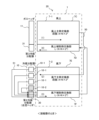
- FIG. 22 is a configuration diagram schematically showing the configuration of the heat exchanger according to Embodiment 3.
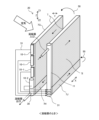
- FIG. 23 is a perspective view showing a configuration of a heat exchanger according to Embodiment 3.
- FIG. 22 and 23 show the case where the heat exchanger according to Embodiment 3 functions as an evaporator.
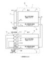
- FIG. 24 is a configuration diagram schematically showing the configuration of the heat exchanger according to Embodiment 3.
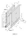
- FIG. 25 is a perspective view showing a configuration of a heat exchanger according to Embodiment 3.
- FIG. 24 and 25 show the case where the heat exchanger according to Embodiment 3 functions as a condenser.
- FIGS. 22 to 25 the same reference numerals are assigned to the configurations that are the same as or correspond to those of the first and second embodiments, and the description of these configurations will be omitted as appropriate.
- the heat transfer tubes 70 of the heat exchange section 7 are arranged in two rows on the windward side and the leeward side in the direction of air flow. are placed in The direction in which air flows is the Y direction, which intersects with the X direction and the Z direction, as indicated by white arrows in FIGS. 23 and 25 .
- the upper left is the windward side and the lower right side is the leeward side.
- 23 and 25 are opposite to those in FIGS. 18 and 21 of the second embodiment. Therefore, the windward side and the leeward side in FIGS. 23 and 25 are opposite to the windward side and the leeward side in FIGS. 18 and 21 of the second embodiment.
- the heat exchange section 7 includes an upwind heat exchange section 7-1 including an upwind heat transfer tube row forming one of the two rows arranged on the windward side, and a leeward heat exchange section 7-2 including a row of leeward heat transfer tubes forming a row arranged side by side.
- the downwind heat exchange section 7-2 has basically the same configuration as the modified example of the first embodiment. A detailed description will be given below.
- the windward heat exchange section 7-1 has an upwind main heat exchange section 7G and an upwind auxiliary heat exchange section 7H.
- the upwind main heat exchange section 7G has a first number of stages. The first number of stages is, for example, K+N ⁇ 2X .
- the upwind auxiliary heat exchange section 7H is arranged side by side in the Z direction with respect to the upwind main heat exchange section 7G. Specifically, the upwind auxiliary heat exchange section 7H is installed below the upwind main heat exchange section 7G.
- the upwind auxiliary heat exchange section 7H has a second number of stages that is less than the first number of stages. Assuming that the total number of stages of the upwind heat exchange section 7-1 is L, the second number of stages is L ⁇ (K+N ⁇ 2 X ).
- a refrigerant distributor 10 is connected to one end of the upwind main heat exchange section 7G.
- the configuration of the refrigerant distributor 10 is the same as that of the refrigerant distributor 10 shown in the first embodiment.
- a second refrigerant distributor 30A is connected to one end of the upwind auxiliary heat exchange section 7H.
- the second refrigerant distributor 30A is a distributor for the auxiliary heat exchange section.
- the configuration of the second refrigerant distributor 30A is, for example, a communication header.
- the leeward heat exchange section 7-2 has a leeward main heat exchange section 7I and a leeward auxiliary heat exchange section 7J.
- the leeward main heat exchange section 7I has a first number of stages. The first number of stages is, for example, K+N ⁇ 2X .
- the leeward auxiliary heat exchange section 7J is arranged side by side in the Z direction with respect to the leeward main heat exchange section 7I. Specifically, the leeward auxiliary heat exchange section 7J is installed below the leeward main heat exchange section 7I.
- the leeward auxiliary heat exchange section 7J has a second number of stages that is smaller than the first number of stages. Assuming that the total number of stages of the downwind heat exchange section 7-2 is L, the second number of stages is L ⁇ (K+N ⁇ 2 X ).
- the first number of stages and the second number of stages in the upwind heat exchange section 7-1 may be the same as or different from the first number of stages and the second number of stages in the downwind heat exchange section 7-2. good.
- the case where the first number of stages and the second number of stages in the upwind heat exchange section 7-1 are the same as the first number of stages and the second number of stages in the downwind heat exchange section 7-2 is taken as an example. explain.
- a gas header 11 is connected to one end of the leeward main heat exchange section 7I.
- a third refrigerant distributor 31A is connected to one end of the leeward auxiliary heat exchange section 7J.
- coolant distributors are distributors for auxiliary heat exchange parts.
- the third refrigerant distributor 31 is composed of, for example, a confluence header.
- the configuration of the confluence header may be the same as that of the second refrigerant distributor 30 shown in the second embodiment.
- the heat transfer tubes 70 included in the upwind heat transfer tube array of the upwind heat exchange section 7-1 and the heat transfer tubes 70 included in the leeward heat transfer tube array of the leeward heat exchange section 7-2 are as shown in FIG. , is connected by a joint 50 . Description of the joint 50 is omitted.
- the refrigerant flows in the order indicated by arrows (1), (2), (3), and (4) in FIG. That is, when the heat exchange section 7 functions as an evaporator, the refrigerant flows through the upwind auxiliary heat exchange section 7H, the leeward auxiliary heat exchange section 7J, the upwind main heat exchange section 7G, and the leeward main heat exchange section 7I in this order. flow.
- the heat exchange section 7 functions as a condenser, as shown in FIG. 24, the refrigerant flows in the order indicated by arrows (1), (2), (3), and (4) flow. That is, when the heat exchange section 7 functions as a condenser, the refrigerant flows through the leeward main heat exchange section 7I, the windward main heat exchange section 7G, the leeward auxiliary heat exchange section 7J, and the upwind auxiliary heat exchange section 7H in this order. flow.
- Embodiment 3 when the heat exchange section 7 functions as an evaporator, the refrigerant flow and the air flow are parallel flows, as shown in FIG. On the other hand, as shown in FIG. 25, when the heat exchange section 7 functions as a condenser, the refrigerant flows and the air flow countercurrently.
- Embodiment 3 As described above, in Embodiment 3, as in Embodiments 1 and 2, refrigerant distributor 10 composed of distributor 10-1 and communication header 10-2 is used. , effects similar to those of the first and second embodiments can be obtained. That is, in Embodiment 3 as well, the heat exchange section 7 having the optimal number of stages that maximizes the year-round energy consumption efficiency APF of the air conditioner 1 while distributing the refrigerant evenly can be realized.
- Embodiment 3 when the heat exchange section 7 functions as a condenser, as shown in FIG. 7J, and the windward auxiliary heat exchange section 7H.
- the outdoor heat exchange portion 7a of the outdoor heat exchanger 20a in FIG. 1 functions as a condenser, so the direction in which the refrigerant flows and the direction in which the air flows are opposite to each other, so the temperature difference between the air and the refrigerant must be large. is possible, and the heat exchange performance is improved.
- Embodiment 4 A heat exchanger according to Embodiment 4 will be described with reference to FIGS. 26 to 31. FIG.
- FIG. 26 is a configuration diagram schematically showing the configuration of the heat exchanger according to Embodiment 4.
- FIG. 27 is a perspective view showing the configuration of a heat exchanger according to Embodiment 4.
- FIG. 26 and 27 show the case where the heat exchanger according to Embodiment 4 functions as an evaporator.
- FIG. 28 is a configuration diagram schematically showing the configuration of the heat exchanger according to Embodiment 4.
- FIG. 29 is a perspective view showing the configuration of a heat exchanger according to Embodiment 4.
- FIG. 28 and 29 show the case where the heat exchanger according to Embodiment 4 functions as a condenser.
- FIG. 30 is an explanatory diagram illustrating a case where refrigerant stagnation occurs in a general heat exchanger.
- a liquid pipe 91 is a refrigerant distributor composed of a communication header
- a gas pipe 90 is a gas header.
- a heat transfer pipe 92 is connected to the gas pipe 90
- a connection pipe 93 is connected to the liquid pipe 91 .
- FIG. 30 will be described later.
- FIG. 31 is a cross-sectional view showing the configuration of the communication header and the second refrigerant distributor of the refrigerant distributor provided in the heat exchanger according to the fourth embodiment.
- FIGS. 26 to 31 the same reference numerals are assigned to the same or corresponding configurations as in Embodiment 1, and the description of these configurations will be omitted as appropriate.
- the configuration of the heat exchange section 7 according to the fourth embodiment is basically the same as that of the second embodiment.
- the difference between the fourth embodiment and the second embodiment is that in the fourth embodiment, the communication header 10-2A of the refrigerant distributor 10 and the second refrigerant distributor 30B are integrated.
- Other configurations and operations are the same as those of the second embodiment.
- the communication header 10-2A and the second refrigerant distributor 30B are integrated.
- the second refrigerant distributor 30B is composed of a confluence header.
- the confluence header that constitutes the second refrigerant distributor 30B has an internal space divided into a plurality of sub-internal spaces 30Ba by a first partition plate 30Bb in accordance with the heat transfer tubes 70 connected thereto.
- the sub-internal space 30Ba arranged at the highest position and the internal space of the communication header 10-2A are separated from each other as shown in FIG.
- a through hole 61 is formed in the second partition plate 60 so as to pass through the plate thickness of the second partition plate 60 . Therefore, the sub-internal space 30Ba located at the highest position communicates with the internal space of the communication header 10-2A through the through hole 61. As shown in FIG.
- the second refrigerant distributor 30 and the refrigerant distributor 10 are connected by the connecting pipe 51 as shown in FIG.
- the connecting pipe 51 connecting the second refrigerant distributor 30B and the refrigerant distributor 10 is The number is smaller than that of the second embodiment.
- this connection connects the sub-internal space 30Ba located at the highest position and the internal space of the communication header 10-2A. This is because the pipe 51 is no longer necessary.
- connection pipe 51 that connects the second refrigerant distributor 30B connected to the leeward auxiliary heat exchange section 7F and the refrigerant distributor 10 connected to the leeward main heat exchange section 7E can reduce the number of Therefore, in the heat exchanger 20 having the same housing size, the size of the heat exchanging portion 7, particularly the heat transfer area of the heat exchanging portion 7, can be increased accordingly. As a result, the heat exchange performance of the heat exchange portion 7 can be improved.
- Embodiment 4 As described above, in Embodiment 4, as in Embodiments 1 to 3, refrigerant distributor 10 composed of distributor 10-1 and communication header 10-2 is used. Effects similar to those of forms 1 to 3 can be obtained. That is, in Embodiment 4 as well, the heat exchange section 7 having the optimal number of stages that maximizes the year-round energy consumption efficiency APF of the air conditioner 1 while distributing the refrigerant evenly can be realized.
- the number of connection pipes 51 connecting the second refrigerant distributor 30B connected to the leeward auxiliary heat exchange section 7F and the refrigerant distributor 10 connected to the leeward main heat exchange section 7E is can be reduced. Therefore, in the heat exchanger 20 having the same housing size, the size of the heat exchanging portion 7, particularly the heat transfer area of the heat exchanging portion 7, can be increased accordingly. As a result, the heat exchange performance of the heat exchange portion 7 can be improved.
- the heat transfer tubes 70 are flat tubes. However, it is not limited to that case.
- the heat transfer tube 70 may be, for example, a circular tube. Even in that case, the same effect as in the first to fourth embodiments can be obtained. That is, even when the heat transfer tube 70 is a circular tube, the refrigerant distributor of the heat exchanger includes one or more distributors that have a collision wall inside and distribute the refrigerant by colliding with the collision wall. a communication header for distributing coolant through the communication space. Also, the branch number K of the communication header is set to a value smaller than the branch number M of the distributor.
- one or more distributors having a configuration that facilitates even distribution of the refrigerant are used. This makes it possible to evenly distribute the refrigerant throughout the heat exchanger.
- a communication header with a branch number K smaller than M is also used so as not to be hindered by the restriction of "every M stages" depending on the branch number M of the distributor. Thereby, the number of stages of the heat exchanger can be freely selected. As a result, it is possible to realize a design with the optimum number of stages that maximizes the performance of the heat exchanger.
Landscapes
- Engineering & Computer Science (AREA)
- Physics & Mathematics (AREA)
- Thermal Sciences (AREA)
- Mechanical Engineering (AREA)
- General Engineering & Computer Science (AREA)
- Heat-Exchange Devices With Radiators And Conduit Assemblies (AREA)
Priority Applications (4)
| Application Number | Priority Date | Filing Date | Title |
|---|---|---|---|
| EP22924754.9A EP4474734A4 (en) | 2022-02-02 | 2022-02-02 | HEAT EXCHANGER AND AIR CONDITIONING DEVICE |
| PCT/JP2022/004016 WO2023148841A1 (ja) | 2022-02-02 | 2022-02-02 | 熱交換器および空気調和装置 |
| JP2023578241A JPWO2023148841A1 (https=) | 2022-02-02 | 2022-02-02 | |
| US18/714,339 US20250020420A1 (en) | 2022-02-02 | 2022-02-02 | Heat exchanger and air-conditioning apparatus |
Applications Claiming Priority (1)
| Application Number | Priority Date | Filing Date | Title |
|---|---|---|---|
| PCT/JP2022/004016 WO2023148841A1 (ja) | 2022-02-02 | 2022-02-02 | 熱交換器および空気調和装置 |
Publications (1)
| Publication Number | Publication Date |
|---|---|
| WO2023148841A1 true WO2023148841A1 (ja) | 2023-08-10 |
Family
ID=87553352
Family Applications (1)
| Application Number | Title | Priority Date | Filing Date |
|---|---|---|---|
| PCT/JP2022/004016 Ceased WO2023148841A1 (ja) | 2022-02-02 | 2022-02-02 | 熱交換器および空気調和装置 |
Country Status (4)
| Country | Link |
|---|---|
| US (1) | US20250020420A1 (https=) |
| EP (1) | EP4474734A4 (https=) |
| JP (1) | JPWO2023148841A1 (https=) |
| WO (1) | WO2023148841A1 (https=) |
Cited By (2)
| Publication number | Priority date | Publication date | Assignee | Title |
|---|---|---|---|---|
| WO2025203542A1 (ja) * | 2024-03-29 | 2025-10-02 | 三菱電機株式会社 | 熱交換器、および冷凍サイクル装置 |
| WO2025203543A1 (ja) * | 2024-03-29 | 2025-10-02 | 三菱電機株式会社 | 熱交換器、および冷凍サイクル装置 |
Citations (5)
| Publication number | Priority date | Publication date | Assignee | Title |
|---|---|---|---|---|
| WO2014184918A1 (ja) * | 2013-05-15 | 2014-11-20 | 三菱電機株式会社 | 積層型ヘッダー、熱交換器、及び、空気調和装置 |
| CN104913678A (zh) * | 2015-06-24 | 2015-09-16 | 台州龙江化工机械科技有限公司 | 一种管壳式干式蒸发器的均液装置 |
| WO2015162678A1 (ja) * | 2014-04-21 | 2015-10-29 | 三菱電機株式会社 | 積層型ヘッダー、熱交換器、及び、空気調和装置 |
| WO2016056063A1 (ja) * | 2014-10-07 | 2016-04-14 | 三菱電機株式会社 | 熱交換器、及び、空気調和装置 |
| JP6214789B2 (ja) | 2014-11-04 | 2017-10-18 | 三菱電機株式会社 | 積層型ヘッダ、熱交換器、及び、空気調和装置 |
Family Cites Families (2)
| Publication number | Priority date | Publication date | Assignee | Title |
|---|---|---|---|---|
| EP3205967B1 (en) * | 2014-10-07 | 2019-09-04 | Mitsubishi Electric Corporation | Heat exchanger and air conditioning device |
| EP3575730A4 (en) * | 2017-01-24 | 2020-01-15 | Mitsubishi Electric Corporation | HEAT SOURCE SIDE UNIT AND REFRIGERATION CYCLE DEVICE |
-
2022
- 2022-02-02 US US18/714,339 patent/US20250020420A1/en active Pending
- 2022-02-02 WO PCT/JP2022/004016 patent/WO2023148841A1/ja not_active Ceased
- 2022-02-02 EP EP22924754.9A patent/EP4474734A4/en not_active Withdrawn
- 2022-02-02 JP JP2023578241A patent/JPWO2023148841A1/ja active Pending
Patent Citations (5)
| Publication number | Priority date | Publication date | Assignee | Title |
|---|---|---|---|---|
| WO2014184918A1 (ja) * | 2013-05-15 | 2014-11-20 | 三菱電機株式会社 | 積層型ヘッダー、熱交換器、及び、空気調和装置 |
| WO2015162678A1 (ja) * | 2014-04-21 | 2015-10-29 | 三菱電機株式会社 | 積層型ヘッダー、熱交換器、及び、空気調和装置 |
| WO2016056063A1 (ja) * | 2014-10-07 | 2016-04-14 | 三菱電機株式会社 | 熱交換器、及び、空気調和装置 |
| JP6214789B2 (ja) | 2014-11-04 | 2017-10-18 | 三菱電機株式会社 | 積層型ヘッダ、熱交換器、及び、空気調和装置 |
| CN104913678A (zh) * | 2015-06-24 | 2015-09-16 | 台州龙江化工机械科技有限公司 | 一种管壳式干式蒸发器的均液装置 |
Non-Patent Citations (1)
| Title |
|---|
| See also references of EP4474734A4 |
Cited By (2)
| Publication number | Priority date | Publication date | Assignee | Title |
|---|---|---|---|---|
| WO2025203542A1 (ja) * | 2024-03-29 | 2025-10-02 | 三菱電機株式会社 | 熱交換器、および冷凍サイクル装置 |
| WO2025203543A1 (ja) * | 2024-03-29 | 2025-10-02 | 三菱電機株式会社 | 熱交換器、および冷凍サイクル装置 |
Also Published As
| Publication number | Publication date |
|---|---|
| US20250020420A1 (en) | 2025-01-16 |
| EP4474734A1 (en) | 2024-12-11 |
| EP4474734A4 (en) | 2025-03-12 |
| JPWO2023148841A1 (https=) | 2023-08-10 |
Similar Documents
| Publication | Publication Date | Title |
|---|---|---|
| JP6352401B2 (ja) | 空気調和装置 | |
| US9651317B2 (en) | Heat exchanger and air conditioner | |
| US10309701B2 (en) | Heat exchanger and air conditioner | |
| JP6091641B2 (ja) | 熱交換器、及び、空気調和装置 | |
| JP5195733B2 (ja) | 熱交換器及びこれを備えた冷凍サイクル装置 | |
| JP5741658B2 (ja) | 熱交換器及び空気調和機 | |
| WO2015025702A1 (ja) | 熱交換器、空調機、冷凍サイクル装置及び熱交換器の製造方法 | |
| JPWO2017183180A1 (ja) | 熱交換器 | |
| WO2023148841A1 (ja) | 熱交換器および空気調和装置 | |
| JP6253814B2 (ja) | 熱交換器、及び冷凍サイクル装置 | |
| JP6742112B2 (ja) | 熱交換器及び空気調和機 | |
| JP2015055411A (ja) | 熱交換器および空気調和機 | |
| JP7399286B2 (ja) | 熱交換器および冷凍サイクル装置 | |
| JP2019060596A (ja) | 熱交換器及びそれを備えた空気調和装置 | |
| JP7414845B2 (ja) | 冷凍サイクル装置 | |
| JP6198976B2 (ja) | 熱交換器、及び冷凍サイクル装置 | |
| JP2019060513A (ja) | 熱交換器及びそれを備えた空気調和装置 | |
| KR102719518B1 (ko) | 냉동사이클의 열교환기 | |
| JP6853867B2 (ja) | 熱交換器及び空気調和機 | |
| WO2023199466A1 (ja) | 熱交換器及びこれを有する空気調和装置 | |
| WO2025169459A1 (ja) | 熱交換器及び空気調和装置 | |
| WO2025182083A1 (ja) | 熱交換器、熱交換器を備えた空気調和装置の室外機、および、空気調和装置の室外機を備えた空気調和装置 | |
| JP2019060512A (ja) | 空気調和装置 | |
| WO2024252674A1 (ja) | 空気調和装置 | |
| JP2025144516A (ja) | 熱交換器、この熱交換器を用いた熱交換システム及びこの熱交換器を用いた空気調和機 |
Legal Events
| Date | Code | Title | Description |
|---|---|---|---|
| 121 | Ep: the epo has been informed by wipo that ep was designated in this application |
Ref document number: 22924754 Country of ref document: EP Kind code of ref document: A1 |
|
| ENP | Entry into the national phase |
Ref document number: 2023578241 Country of ref document: JP Kind code of ref document: A |
|
| WWE | Wipo information: entry into national phase |
Ref document number: 18714339 Country of ref document: US |
|
| WWE | Wipo information: entry into national phase |
Ref document number: 2022924754 Country of ref document: EP |
|
| NENP | Non-entry into the national phase |
Ref country code: DE |
|
| ENP | Entry into the national phase |
Ref document number: 2022924754 Country of ref document: EP Effective date: 20240902 |
|
| WWW | Wipo information: withdrawn in national office |
Ref document number: 2022924754 Country of ref document: EP |