WO2023145501A1 - ガス検出装置およびガス検出システム - Google Patents
ガス検出装置およびガス検出システム Download PDFInfo
- Publication number
- WO2023145501A1 WO2023145501A1 PCT/JP2023/000913 JP2023000913W WO2023145501A1 WO 2023145501 A1 WO2023145501 A1 WO 2023145501A1 JP 2023000913 W JP2023000913 W JP 2023000913W WO 2023145501 A1 WO2023145501 A1 WO 2023145501A1
- Authority
- WO
- WIPO (PCT)
- Prior art keywords
- gas
- detected
- detection
- sensor
- gas sensor
- Prior art date
- Legal status (The legal status is an assumption and is not a legal conclusion. Google has not performed a legal analysis and makes no representation as to the accuracy of the status listed.)
- Ceased
Links
Images




Classifications
-
- G—PHYSICS
- G01—MEASURING; TESTING
- G01N—INVESTIGATING OR ANALYSING MATERIALS BY DETERMINING THEIR CHEMICAL OR PHYSICAL PROPERTIES
- G01N27/00—Investigating or analysing materials by the use of electric, electrochemical, or magnetic means
- G01N27/26—Investigating or analysing materials by the use of electric, electrochemical, or magnetic means by investigating electrochemical variables; by using electrolysis or electrophoresis
- G01N27/416—Systems
-
- G—PHYSICS
- G01—MEASURING; TESTING
- G01N—INVESTIGATING OR ANALYSING MATERIALS BY DETERMINING THEIR CHEMICAL OR PHYSICAL PROPERTIES
- G01N27/00—Investigating or analysing materials by the use of electric, electrochemical, or magnetic means
- G01N27/02—Investigating or analysing materials by the use of electric, electrochemical, or magnetic means by investigating impedance
- G01N27/04—Investigating or analysing materials by the use of electric, electrochemical, or magnetic means by investigating impedance by investigating resistance
- G01N27/12—Investigating or analysing materials by the use of electric, electrochemical, or magnetic means by investigating impedance by investigating resistance of a solid body in dependence upon absorption of a fluid; of a solid body in dependence upon reaction with a fluid, for detecting components in the fluid
-
- G—PHYSICS
- G01—MEASURING; TESTING
- G01N—INVESTIGATING OR ANALYSING MATERIALS BY DETERMINING THEIR CHEMICAL OR PHYSICAL PROPERTIES
- G01N33/00—Investigating or analysing materials by specific methods not covered by groups G01N1/00 - G01N31/00
- G01N33/0004—Gaseous mixtures, e.g. polluted air
- G01N33/0009—General constructional details of gas analysers, e.g. portable test equipment
- G01N33/0027—General constructional details of gas analysers, e.g. portable test equipment concerning the detector
- G01N33/0031—General constructional details of gas analysers, e.g. portable test equipment concerning the detector comprising two or more sensors, e.g. a sensor array
-
- G—PHYSICS
- G01—MEASURING; TESTING
- G01N—INVESTIGATING OR ANALYSING MATERIALS BY DETERMINING THEIR CHEMICAL OR PHYSICAL PROPERTIES
- G01N33/00—Investigating or analysing materials by specific methods not covered by groups G01N1/00 - G01N31/00
- G01N33/0004—Gaseous mixtures, e.g. polluted air
- G01N33/0009—General constructional details of gas analysers, e.g. portable test equipment
- G01N33/0027—General constructional details of gas analysers, e.g. portable test equipment concerning the detector
- G01N33/0036—General constructional details of gas analysers, e.g. portable test equipment concerning the detector specially adapted to detect a particular component
- G01N33/0044—Sulphides, e.g. H2S
-
- G—PHYSICS
- G01—MEASURING; TESTING
- G01N—INVESTIGATING OR ANALYSING MATERIALS BY DETERMINING THEIR CHEMICAL OR PHYSICAL PROPERTIES
- G01N33/00—Investigating or analysing materials by specific methods not covered by groups G01N1/00 - G01N31/00
- G01N33/0004—Gaseous mixtures, e.g. polluted air
- G01N33/0009—General constructional details of gas analysers, e.g. portable test equipment
- G01N33/0027—General constructional details of gas analysers, e.g. portable test equipment concerning the detector
- G01N33/0036—General constructional details of gas analysers, e.g. portable test equipment concerning the detector specially adapted to detect a particular component
- G01N33/0047—Organic compounds
-
- G—PHYSICS
- G01—MEASURING; TESTING
- G01N—INVESTIGATING OR ANALYSING MATERIALS BY DETERMINING THEIR CHEMICAL OR PHYSICAL PROPERTIES
- G01N33/00—Investigating or analysing materials by specific methods not covered by groups G01N1/00 - G01N31/00
- G01N33/48—Biological material, e.g. blood, urine; Haemocytometers
- G01N33/483—Physical analysis of biological material
-
- G—PHYSICS
- G01—MEASURING; TESTING
- G01N—INVESTIGATING OR ANALYSING MATERIALS BY DETERMINING THEIR CHEMICAL OR PHYSICAL PROPERTIES
- G01N33/00—Investigating or analysing materials by specific methods not covered by groups G01N1/00 - G01N31/00
- G01N33/48—Biological material, e.g. blood, urine; Haemocytometers
- G01N33/483—Physical analysis of biological material
- G01N33/497—Physical analysis of biological material of gaseous biological material, e.g. breath
-
- Y—GENERAL TAGGING OF NEW TECHNOLOGICAL DEVELOPMENTS; GENERAL TAGGING OF CROSS-SECTIONAL TECHNOLOGIES SPANNING OVER SEVERAL SECTIONS OF THE IPC; TECHNICAL SUBJECTS COVERED BY FORMER USPC CROSS-REFERENCE ART COLLECTIONS [XRACs] AND DIGESTS
- Y02—TECHNOLOGIES OR APPLICATIONS FOR MITIGATION OR ADAPTATION AGAINST CLIMATE CHANGE
- Y02A—TECHNOLOGIES FOR ADAPTATION TO CLIMATE CHANGE
- Y02A50/00—TECHNOLOGIES FOR ADAPTATION TO CLIMATE CHANGE in human health protection, e.g. against extreme weather
- Y02A50/20—Air quality improvement or preservation, e.g. vehicle emission control or emission reduction by using catalytic converters
Definitions
- the present disclosure relates to a gas detection device that detects the concentration of gas, and a gas detection system that includes the gas detection device.
- Patent Document 1 A system for detecting odorous gas generated from stool excreted by a subject is known (for example, Patent Document 1).
- a gas detection device includes a sample gas sampling unit that samples a sample gas including a first gas to be detected and a second gas to be detected; a gas detection unit including a plurality of gas sensors including a first gas sensor and a second gas sensor capable of detecting both of a second detection target gas, wherein the first gas sensor and the second gas sensor are capable of detecting the first detection target gas;
- the relative relationship between the detection sensitivity with respect to the detection gas and the detection sensitivity with respect to the second gas to be detected is different from each other.
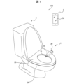
- FIG. 1 is an external view showing an example of the configuration of an analysis system according to an embodiment of the present disclosure
- FIG. 1 is a schematic diagram showing an example of a configuration of a gas detection device according to an embodiment of the present disclosure
- FIG. 1 is a block diagram showing an example configuration of a gas detection device according to an embodiment of the present disclosure
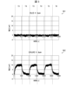
- FIG. 4 is a graph showing an example of variations in the first detection signal due to hydrogen sulfide and methyl mercaptan.
- FIG. 10 is a graph showing an example of variations in the second detection signal due to hydrogen sulfide and methyl mercaptan;
- FIG. 4 is a partial cross-sectional view showing an example of the configuration of a first gas sensor included in the gas sensor group;
- FIG. 11 is a schematic diagram showing an example of the configuration of a gas detection device according to Embodiment 3;
- FIG. 11 is a schematic diagram showing an example of the configuration of a gas detection device according to Embodiment 5;
- FIG. 1 is an external view showing an example configuration of an analysis system 100 according to an embodiment of the present disclosure.
- Each figure referred to in this specification is a schematic diagram showing only a part of members in a simplified manner for describing the embodiment for convenience of explanation.
- analysis system 100 may include any components not shown in the figures to which this specification refers. Also, the dimensions of the members in each drawing do not faithfully represent the actual dimensions of the constituent members, the dimensional ratios of the respective members, and the like.
- the analysis system 100 as shown in FIG. 1 can be called a "gas detection system” or a “gas analysis system”.
- the analysis system 100 includes a gas detection device 1 and electronic equipment (terminal device) 3 .
- the gas detection device 1 detects gas generated from the specimen of the subject.
- the detected gas can be used for analysis of the subject's health condition, and the like.
- the specimen of the subject may be, for example, a part of the tissue or urine of the subject, but in this embodiment, it is the stool of the subject.
- a chemical substance that is a target chemical substance to be detected by the gas sensor group 24 (to be described later) provided in the gas detection device 1 and that can exist as a gas is referred to as a "detection target gas".
- the gas to be detected may be of one type or of multiple types.
- the gas to be detected may be contained, for example, in the gas (sample gas) discharged from the subject's stool.
- the concentration of the detection target gas is intended to be the concentration in the sample gas of the chemical substance to be detected.
- the gas detection device 1 is installed, for example, in a flush toilet bowl 2, as shown in FIG.
- the toilet bowl 2 includes a toilet bowl 2A and a toilet seat 2B.
- the gas detection device 1 may be installed anywhere on the toilet bowl 2 .
- the gas detection device 1 may be arranged from between the toilet bowl 2A and the toilet seat 2B to the outside of the toilet 2, as shown in FIG. Part of the gas detection device 1 may be embedded in the toilet seat 2B.
- the toilet bowl 2A of the toilet bowl 2 can be discharged with feces of the subject.
- the gas detection device 1 can obtain a sample gas in which gas generated from stool discharged into the toilet bowl 2A is mixed with outside air.
- the gas detection device 1 can detect the type, concentration, etc. of the detection target gas contained in the sample gas.
- the gas detection device 1 can transmit detection results to the electronic device 3 .
- the toilet bowl 2 can be installed in a toilet room such as a house or a hospital.
- the electronic device 3 is, for example, a smart phone used by the subject.
- the electronic device 3 is not limited to a smart phone, and may be any electronic device.
- the electronic device 3 may be inside the toilet room or outside the toilet room.
- the electronic device 3 can receive the detection result from the gas detection device 1 by wireless communication or wired communication. In this case, the electronic device 3 may receive the detection result from the gas detection device 1 via the server. The electronic device 3 can display the received detection result on the display unit 3A.
- the display unit 3A may include a display capable of displaying characters and the like, and a touch screen capable of detecting contact with a user's (subject's) finger or the like.
- the display may include a display device such as a liquid crystal display (LCD), an organic electroluminescence display (OELD) or an inorganic electroluminescence display (IELD). .
- the detection method of the touch screen may be any method such as a capacitance method, a resistive film method, a surface acoustic wave method, an ultrasonic method, an infrared method, an electromagnetic induction method, or a load detection method.
- FIG. 2 is a schematic diagram showing an example of the configuration of the gas detection device 1 according to one embodiment.
- FIG. 3 is a block diagram showing an example of the configuration of the gas detection device 1.
- the gas detection device 1 is installed in the toilet bowl 2, collects a sample gas containing gas discharged from the subject's stool, and detects the type and concentration of the gas to be detected contained in the sample gas. can be detected. Further, the gas detection device 1 can transmit information indicating the type and concentration of the detected gas to be detected to the electronic device 3 as a detection result. As shown in FIGS.
- the gas detection device 1 includes a housing 10, a sampling section 21 (sample gas sampling section), a storage pump 22, a storage tank 25, a sensor chamber 23 (gas detection section), and a gas sensor group 24. , a chamber pump 26 , a discharge path 30 , a control section 40 , a subject detection section 50 , a communication section 51 and a storage section 52 .
- Housing 10 accommodates various components of the gas detection device 1 .
- Housing 10 may be constructed of any material.
- the housing 10 may be made of a material such as metal or resin.
- the collection unit 21 is a tubular member that collects a sample gas in the target space and supplies the collected sample gas into the storage tank 25 .
- the sampling part 21 is exposed to the inside of the toilet bowl 2A and has an opening 211 that opens toward the inside of the toilet bowl 2A. sample gas.
- the sampling part 21 has a sample channel for flowing the sample gas therein.
- the sample flow path is intended to be a flow path through which the collected sample gas moves.
- the sample channel communicates the opening 211 and the sensor chamber 23 .
- a reservoir pump 22 is a pump located on the sample flow path.
- the storage pump 22 may operate under the control of a pump control section 41 (described later).
- reservoir pump 22 may be a pump that operates at a constant delivery rate.
- the storage pump 22 may supply the sample gas from the sampling section 21 into the storage tank 25 .
- the storage tank 25 is located behind the storage pump 22 on the sample flow path, and temporarily stores the sample gas sampled from the sampling section 21 by the storage pump 22 .
- the function of the storage tank 25 is not limited to temporarily storing the sample gas, and may function as part of a flow path that does not store the sample gas.
- the storage tank 25 may be made of resin in the shape of a bag, or may be made of metal in the shape of a cylinder or square.
- the sensor chamber 23 is a chamber that houses the gas sensor group 24 inside. Sensor chamber 23 communicates with reservoir 25 .
- the number of gas sensors included in the gas sensor group 24 housed inside the sensor chamber 23 is not particularly limited.
- the gas sensor group 24 may include any number of gas sensors according to the types and number of gases to be detected.
- the gas sensor group 24 includes a first gas sensor 24a and a second gas sensor 24b. Both the first gas sensor 24a and the second gas sensor 24b are gas sensors capable of detecting both the first gas to be detected and the second gas to be detected. That is, the first gas sensor 24a and the second gas sensor 24b both detect the first gas to be detected and the second gas to be detected.
- the detection signal output from the first gas sensor 24a is referred to as a first detection signal.
- a detection signal output from the second gas sensor 24b is referred to as a second detection signal.
- the gas sensor group 24 may be a set of sensors that output different detection signals according to the concentration of the gas to be detected.
- a sensor constituting the gas sensor group 24 a sensor whose detection signal intensity changes according to the concentration of the gas to be detected will be described as an example, but the sensor is not limited to this.
- the sensors constituting the gas sensor group 24 can output to the signal acquisition section 42 of the control section 40 a detection signal having an intensity corresponding to the concentration of the detection target gas that can be contained in the sample gas.
- the gas detection device 1 may include multiple gas sensors. Further, the plurality of gas sensors may be capable of outputting detection signals according to concentrations of different types of detection target gases. Thereby, the gas detection device 1 can analyze the concentration of a plurality of types of detection target gases.
- Both the first gas to be detected and the second gas to be detected may be gases containing sulfur atoms in their composition formulas. Sensors that are sensitive to one type of gas that has a sulfur atom in its formula tend to be sensitive to another type of gas that has a sulfur atom in its formula. Therefore, when the sample gas contains multiple types of detection target gases that contain sulfur atoms in the composition formula, it is difficult to detect the concentration of any one of the multiple types of detection target gases with a single gas sensor. is. According to the gas detection device 1, instead of detecting individual concentrations of a plurality of types of detection target gases containing sulfur atoms in their compositional formulas, the concentrations are detected based on the first detection signal and the second detection signal, as will be described later. can be estimated with high accuracy.
- the first gas to be detected may be hydrogen sulfide.
- the second gas to be detected may be methyl mercaptan.
- Hydrogen sulfide and methyl mercaptan are gas species that are particularly difficult to detect in individual gas concentration with a single gas sensor. According to the gas detection device 1, the concentrations of hydrogen sulfide and methyl mercaptan can be accurately estimated based on the first detection signal and the second detection signal, as described later, instead of detecting individual concentrations.
- the first gas to be detected and the second gas to be detected may be gas containing a sulfur atom in its composition formula, other than hydrogen sulfide and methyl mercaptan.
- the first gas to be detected and the second gas to be detected are not limited to gases containing sulfur atoms in their compositional formulas.
- both the first gas to be detected and the second gas to be detected may be gases containing nitrogen atoms.
- the sample gas contains multiple types of detection target gases that contain nitrogen atoms in the composition formula, it is difficult to detect the concentration of any one of the multiple types of detection target gases with a single gas sensor. be.
- the gas detection device 1 instead of detecting individual concentrations of a plurality of types of detection target gases containing nitrogen atoms in their composition formulas, the concentrations are detected based on the first detection signal and the second detection signal, as will be described later. can be estimated with high accuracy.
- FIG. 4 is a graph showing an example of variation in the first detection signal output from the first gas sensor 24a due to hydrogen sulfide and methyl mercaptan.
- the horizontal axis indicates time, and the vertical axis indicates the first detection signal (voltage).
- reference numeral 401 is a graph showing an example of variation in the first detection signal caused by hydrogen sulfide with a concentration of 0.3 ppm.
- reference numeral 402 is a graph showing an example of variation in the first detection signal due to methyl mercaptan having a concentration of 0.3 ppm.
- a period T1 in FIG. 4 is a period during which hydrogen sulfide or methyl mercaptan is supplied to the first gas sensor 24a.
- the first detection signal shows clear fluctuations due to hydrogen sulfide between period T1 and period T2.
- the first detection signal shows slight fluctuations due to methyl mercaptan between periods T1 and T2, but the fluctuations are small compared to the fluctuations due to hydrogen sulfide. . That is, the detection sensitivity of the first gas sensor 24a to hydrogen sulfide is greater than the detection sensitivity of the first gas sensor 24a to methyl mercaptan.
- FIG. 5 is a graph showing an example of variations in the second detection signal output from the second gas sensor 24b caused by hydrogen sulfide and methyl mercaptan.
- the horizontal axis indicates time, and the vertical axis indicates the second detection signal (voltage).
- reference numeral 501 is a graph showing an example of variations in the second detection signal caused by hydrogen sulfide with a concentration of 0.3 ppm.
- reference numeral 502 is a graph showing an example of variations in the second detection signal due to methyl mercaptan having a concentration of 0.3 ppm.
- a period T3 in FIG. 5 is a period during which hydrogen sulfide or methyl mercaptan is supplied to the second gas sensor 24b.
- the second detection signal shows clear fluctuations due to methyl mercaptan between period T3 and period T4.
- the second detection signal shows slight fluctuations caused by hydrogen sulfide between periods T3 and T4, but the fluctuations are small compared to the fluctuations caused by methyl mercaptan. . That is, the detection sensitivity of the second gas sensor 24b to methyl mercaptan is higher than the detection sensitivity of the second gas sensor 24b to hydrogen sulfide.
- the relative relationship between the detection sensitivity to hydrogen sulfide and the detection sensitivity to methyl mercaptan of the first gas sensor 24a and the second gas sensor 24b may differ from each other. Specifically, when the concentrations of hydrogen sulfide and methyl mercaptan are equal to each other, the ratio of the intensity of the first detection signal due to methyl mercaptan to the intensity of the first detection signal due to hydrogen sulfide is may be smaller than the ratio of the intensity of the second detection signal due to methyl mercaptan to the intensity of the second detection signal resulting from methyl mercaptan.
- the concentrations of hydrogen sulfide and methyl mercaptan can be accurately estimated as described later.
- the chamber pump 26 is a pump that introduces sample gas from the reservoir 25 into the sensor chamber 23 .
- the chamber pump 26 may operate under the control of a pump control section 41 (described later).
- Chamber pump 26 may be, for example, a pump that operates at a constant air delivery rate.
- the discharge amount of the chamber pump 26 may be set smaller than the discharge amount of the storage pump 22 .
- the discharge path 30 may be configured by a tubular member such as a resin tube or a metal or glass pipe.
- the exhaust channel 30 communicates the sensor chamber 23 with the outside of the housing 10 .
- the chamber pump 26 may be provided in the middle of the discharge path 30 .
- the discharge path 30 discharges the exhaust from the sensor chamber 23 to the outside of the gas detection device 1 by the operation of the chamber pump 26 .
- a portion of the discharge channel 30 may be exposed outside the toilet bowl 2A, as shown in FIG.
- control unit 40 The control unit 40 controls the operation of each unit of the gas detection device 1 and estimates the concentration of the detection target gas contained in the sample gas. As shown in FIG. 3 , the controller 40 includes a pump controller 41 , a signal acquirer 42 and an estimator 43 .
- the pump control unit 41 controls operations of the storage pump 22 and the chamber pump 26 . Specifically, the pump control unit 41 operates the storage pump 22 and the chamber pump 26 according to the detection result of the subject detection unit 50 (described later), and stops them after a predetermined time has passed. As a result, the sample gas in the toilet bowl 2A is sucked from the collection part 21 and supplied into the sensor chamber 23 via the storage tank 25 .
- the signal acquisition unit 42 acquires a detection signal corresponding to the type and concentration of the detection target gas contained in the sample gas from each gas sensor included in the gas sensor group 24 . Specifically, the signal acquisition unit 42 acquires the detection signal output from each gas sensor included in the gas sensor group 24 when the operation of the storage pump 22 and the chamber pump 26 by the pump control unit 41 is stopped. you can
- the estimation unit 43 estimates the type and concentration of the detection target gas contained in the sample gas based on the detection signal acquired by the signal acquisition unit 42 from each gas sensor included in the gas sensor group 24 .
- the detection signal acquired from each gas sensor is the detection signal output from the gas sensor.
- the estimation unit 43 estimates the concentrations of the first gas to be detected and the second gas to be detected based on the first detection signal output from the first gas sensor 24a and the second detection signal output from the second gas sensor 24b. You can As described above, both the first gas sensor 24a and the second gas sensor 24b can detect both the first gas to be detected and the second gas to be detected.
- the estimator 43 can uniquely estimate the combination of the concentration of the first gas to be detected and the concentration of the second gas to be detected that match both the first detection signal and the second detection signal.
- the estimation unit 43 may be provided in the control unit 40 of the gas detection device 1 as shown in FIG. Also, the estimation unit 43 may not be provided in the control unit 40 but may be provided on a cloud connected to the gas detection device 1 via a network. When the estimation unit 43 is provided on the cloud, the signal acquisition unit 42 may transmit the detection signal acquired from each gas sensor included in the gas sensor group 24 to the cloud via the network. The estimation unit 43 on the cloud may estimate the type and concentration of the detection target gas based on the detection signal transmitted from the signal acquisition unit 42 .
- the estimation unit 43 uses a concentration estimation model created from the first detection signal and the second detection signal for a plurality of types of teacher gases to estimate the concentrations of the first gas to be detected and the second gas to be detected contained in the sample gas. can be estimated.
- a teacher gas is a sample gas containing a first gas to be detected and a second gas to be detected whose concentrations are known.
- the concentration estimation model is created by machine learning using a set of the first detection signal and second detection signal for the teacher gas and the concentrations of the first and second target gases contained in the teacher gas. good.
- the estimating unit 43 can easily perform estimation by estimating the concentrations of the first detectable gas and the second detectable gas using such a concentration estimation model.
- the subject detection unit 50 may include at least one of an image camera (not shown), a personal identification switch, an infrared sensor, a pressure sensor, and the like.
- the subject detection unit 50 outputs the detection result to the control unit 40 .
- the subject detection unit 50 when the subject detection unit 50 includes an infrared sensor, the subject detection unit 50 detects infrared light reflected from an object irradiated by the infrared sensor, thereby detecting that the subject has entered the toilet room. can be detected. The subject detection unit 50 outputs a signal indicating that the subject has entered the toilet room to the control unit 40 as a detection result.
- the subject detection unit 50 when the subject detection unit 50 includes a pressure sensor, it detects that the subject has sat on the toilet seat 2B by detecting an increase in pressure applied to the toilet seat 2B shown in FIG. can.
- the subject detection unit 50 outputs a signal indicating that the subject has sat on the toilet seat 2B to the control unit 40 as a detection result.
- the subject detection unit 50 when the subject detection unit 50 includes a pressure sensor, it detects that the subject stands up from the toilet seat 2B by detecting a decrease in the pressure applied to the toilet seat 2B shown in FIG. can.
- the subject detection unit 50 outputs a signal indicating that the subject has stood up from the toilet seat 2B to the control unit 40 as a detection result.
- the subject detection unit 50 when the subject detection unit 50 includes an image camera, an individual identification switch, and the like, it collects data such as face images, sitting height, and weight.
- the target person detection unit 50 identifies and detects an individual from the collected data.
- the subject detection unit 50 outputs a signal indicating the identified individual to the control unit 40 as a detection result.
- the subject detection unit 50 identifies (detects) an individual based on the operation of the individual identification switch.
- personal information may be registered (stored) in advance in the storage unit 52 .
- the target person detection unit 50 outputs a signal indicating the specified individual to the control unit 40 as a detection result.
- the subject detection unit 50 may detect that the subject has defecated.
- the subject detection unit 50 outputs a signal indicating that the subject has defecated to the control unit 40 as a detection result.
- the communication unit 51 communicates with the electronic device 3 to present the analysis result of the gas to be detected by the control unit 40 to the subject by, for example, display on the display unit 3A or voice.
- the communication unit 51 may be capable of communicating with an external server.
- the communication method used for communication between the communication unit 51 and the electronic device 3 and the external server may be a short-range wireless communication standard, a wireless communication standard for connecting to a mobile phone network, or a wired communication standard.
- Near field communication standards may include, for example, WiFi (registered trademark), Bluetooth (registered trademark), infrared rays, and Near Field Communication (NFC).
- a wireless communication standard for connecting to a mobile phone network may include, for example, LTE (Long Term Evolution) or a mobile communication system of fourth generation or higher.
- the communication method used for communication between the communication unit 51 and the electronic device 3 and the external server may be a communication standard such as LPWA (Low Power Wide Area) or LPWAN (Low Power Wide Area Network).
- the storage unit 52 is composed of, for example, a semiconductor memory, a magnetic memory, or the like.
- the storage unit 52 stores various information and programs for operating the gas detection device 1 .
- the storage unit 52 may function as a work memory.
- the storage unit 52 may also store, for example, a concentration estimation model for the estimation unit 43 to estimate the concentration of the first detection gas and the second detection gas.
- the gas detection device 1 may include a sampling section 21 , a storage pump 22 , a storage tank 25 , a sensor chamber 23 , a gas sensor group 24 , a chamber pump 26 and a control section 40 .
- the gas sensor group 24 may include a first gas sensor 24a and a second gas sensor 24b.
- the control unit 40 may include an estimation unit 43 .
- the concentration of the detection target gas contained in the sample gas is detected by the gas sensor group 24 including the first gas sensor 24a and the second gas sensor 24b.
- Both the first gas sensor 24a and the second gas sensor 24b may be gas sensors capable of detecting both the first gas to be detected and the second gas to be detected.
- the estimation unit 43 estimates the concentrations of the first gas to be detected and the second gas to be detected.
- the gas detection device 1 can highly accurately estimate the concentration of a gas whose concentration is difficult to measure accurately with a single sensor.
- both the first gas sensor 24a and the second gas sensor 24b may be electrochemical sensors.
- electrochemical sensors By using electrochemical sensors as the first gas sensor 24a and the second gas sensor 24b, the concentrations of the first gas to be detected and the second gas to be detected can be detected with high sensitivity.
- the first gas sensor 24a and the second gas sensor 24b are not limited to electrochemical sensors. Semiconductor) type sensor, sensitive film type sensor, optical sensor, photoacoustic sensor, or the like. As the sensitive film type sensor, a sensitive film stress type sensor or a sensitive film resonance type sensor may be used.
- the gas sensor group 24 may include multiple types of sensors. The first gas sensor 24a and the second gas sensor 24b may be selected according to the first gas to be detected and the second gas to be detected.
- FIG. 6 is a partial cross-sectional view showing an example of the configuration of the first gas sensor 24a included in the gas sensor group 24.
- the first gas sensor 24a may include a case 241, a first electrode 244, a second electrode 245, and electrode pins 246.
- the first gas sensor 24a may include a case 241, a first electrode 244, a second electrode 245, and electrode pins 246.
- the case 241 is a housing that accommodates the first electrode 244 (electrode), the second electrode 245 (electrode), and the electrolytic solution. There may be a reference electrode between the first electrode 244 and the second electrode 245 .
- a vent hole 242 is formed in the case 241 for taking in the sample gas.
- a pre-filter 243 may be provided in the ventilation hole 242 to reduce foreign matter such as dust from entering the case 241 .
- the first electrode 244 and the second electrode 245 may be arranged at positions facing each other within the case 241, for example.
- the first electrode 244 may be arranged on the vent hole 242 side, for example.
- the second electrode 245 may be installed, for example, on the side facing the first electrode 244 within the case 241 . Also, when the first electrode 244 and the second electrode 245 are adjacent to each other, a non-woven fabric may be placed between them.
- the first electrode 244 and the second electrode 245 are electrically connected to each other through the electrolytic solution.
- the first electrode 244, the second electrode 245, and the electrolyte constitute an electrode unit that outputs a signal corresponding to the concentration of the detection target gas contained in the sample gas.
- the first electrode 244 and the second electrode 245 may be carbon-based electrodes.
- the electrolytic solution may contain, for example, sulfuric acid as a main component, but is not limited to this.
- the resistance value between the first electrode 244 and the second electrode 245 changes.
- the degree of change in resistance varies depending on the type and concentration of gas contained in the sample gas.
- the voltage between the first electrode 244 and the second electrode 245 changes according to the type and concentration of gas contained in the sample gas.
- a change in the voltage becomes a signal indicating the type and concentration of the gas contained in the sample gas.
- the electrode pin 246 is a pin for extracting signals output from the first electrode 244 and the second electrode 245 to the outside.
- the first gas sensor 24 a may comprise an electrode pin 246 connected to the first electrode 244 and an electrode pin 246 connected to the second electrode 245 .
- the electrode pin 246 may be made of platinum, for example, but is not limited to this.
- FIG. 7 is a schematic diagram showing an example of the configuration of the gas detection device 1A according to the third embodiment. As shown in FIG. 7, the gas detection device 1A differs from the gas detection device 1 only in that the gas sensor group 24 further includes a third gas sensor 24c.
- the third gas sensor 24c is a gas sensor capable of detecting the first gas to be detected and the second gas to be detected.
- the detection sensitivity of the third gas sensor 24c to the first detectable gas may be different from both the detection sensitivity of the first gas sensor 24a to the first detectable gas and the detection sensitivity of the second gas sensor 24b to the first detectable gas.
- the gas detection device 1A can obtain three types of detection signals for the first gas to be detected and the second gas to be detected. Therefore, the concentrations of the first gas to be detected and the second gas to be detected can be estimated with higher accuracy.
- the gas species of the first gas to be detected and the second gas to be detected are different from those in the first embodiment.
- the first gas to be detected may be hydrogen sulfide or methyl mercaptan.
- the second gas to be detected may be hydrogen, water, ammonia, or alcohol.
- the second gas to be detected is a gas that causes noise or interferes with the output signal from the gas sensor that detects the first gas to be detected. That is, the concentration of the second gas to be detected affects the detection signal from the gas sensor that detects the first gas to be detected. Therefore, in an environment where the second gas to be detected exists, it is difficult to detect the concentration of the first gas to be detected with a single gas sensor.
- the intensity of the second detection signal caused by the first gas to be detected is compared with the intensity of the second detection signal caused by the first gas to be detected.
- the ratio of the strengths of the two detected signals may be greater than one.
- a second detection signal resulting from the second detection gas relative to the intensity of the second detection signal resulting from the first detection gas when the concentrations of the first detection gas and the second detection gas are substantially equal to each other; may be greater than ten. That is, the second gas sensor 24b may be a gas sensor that mainly detects the second gas to be detected.
- the estimation unit 43 can accurately estimate the concentration of the second gas to be detected based on the second detection signal. That is, the estimation unit 43 can also accurately estimate the magnitude of the influence of the concentration of the second gas to be detected on the first detection signal. Therefore, the estimator 43 can accurately estimate the concentration of the first gas to be detected based on the first detection signal.
- the second detection signal output from the second gas sensor 24b has little effect on the estimation of the concentration of the first gas to be detected.
- such a second detection signal is not used as an explanatory variable in the concentration estimation model of the first gas to be detected.
- the second detection signal may also be used as an explanatory variable in the concentration estimation model of the first detected gas.
- the second detection signal may also be used as an explanatory variable in the model for estimating the concentration of the first gas to be detected.
- FIG. 8 is a schematic diagram showing an example of the configuration of the gas detection device 1B according to the fifth embodiment.
- the gas detection device 1B differs from the gas detection device 1 in that the sensor chamber 23 is positioned downstream of the chamber pump 26.
- the concentration of a gas whose concentration is difficult to accurately measure with a single sensor can be estimated with high accuracy.
- the functions of the gas detection devices 1, 1A, and 1B are programs for causing a computer to function as the apparatus, and each control block of the apparatus (especially each part included in the control unit 40). ) can be implemented by a program for causing a computer to function.
- the device comprises a computer having at least one control device (eg processor) and at least one storage device (eg memory) as hardware for executing the program.
- control device eg processor
- storage device eg memory
- the above program may be recorded on one or more computer-readable recording media, not temporary.
- the recording medium may or may not be included in the device.
- the program may be supplied to the device via any transmission medium, wired or wireless.
- part or all of the functions of the above control blocks can be realized by logic circuits.
- an integrated circuit in which logic circuits functioning as the above control blocks are formed is also included in the scope of the present disclosure.
- each process described in each of the above embodiments may be executed by AI (Artificial Intelligence).
- AI Artificial Intelligence
- the AI may operate on the control device, or may operate on another device (for example, an edge computer or a cloud server).
Landscapes
- Chemical & Material Sciences (AREA)
- Health & Medical Sciences (AREA)
- Life Sciences & Earth Sciences (AREA)
- Engineering & Computer Science (AREA)
- Physics & Mathematics (AREA)
- General Physics & Mathematics (AREA)
- Pathology (AREA)
- Immunology (AREA)
- Analytical Chemistry (AREA)
- Biochemistry (AREA)
- General Health & Medical Sciences (AREA)
- Food Science & Technology (AREA)
- Medicinal Chemistry (AREA)
- Combustion & Propulsion (AREA)
- Molecular Biology (AREA)
- Biomedical Technology (AREA)
- Chemical Kinetics & Catalysis (AREA)
- Electrochemistry (AREA)
- Biophysics (AREA)
- Hematology (AREA)
- Urology & Nephrology (AREA)
- Investigating Or Analyzing Materials By The Use Of Fluid Adsorption Or Reactions (AREA)
Priority Applications (3)
| Application Number | Priority Date | Filing Date | Title |
|---|---|---|---|
| US18/833,296 US20250102461A1 (en) | 2022-01-27 | 2023-01-16 | Gas detection apparatus and gas detection system |
| CN202380018203.0A CN118575077A (zh) | 2022-01-27 | 2023-01-16 | 气体检测装置以及气体检测系统 |
| JP2023576791A JP7823086B2 (ja) | 2022-01-27 | 2023-01-16 | ガス検出装置およびガス検出システム |
Applications Claiming Priority (2)
| Application Number | Priority Date | Filing Date | Title |
|---|---|---|---|
| JP2022011291 | 2022-01-27 | ||
| JP2022-011291 | 2022-01-27 |
Publications (1)
| Publication Number | Publication Date |
|---|---|
| WO2023145501A1 true WO2023145501A1 (ja) | 2023-08-03 |
Family
ID=87471312
Family Applications (1)
| Application Number | Title | Priority Date | Filing Date |
|---|---|---|---|
| PCT/JP2023/000913 Ceased WO2023145501A1 (ja) | 2022-01-27 | 2023-01-16 | ガス検出装置およびガス検出システム |
Country Status (4)
| Country | Link |
|---|---|
| US (1) | US20250102461A1 (https=) |
| JP (1) | JP7823086B2 (https=) |
| CN (1) | CN118575077A (https=) |
| WO (1) | WO2023145501A1 (https=) |
Citations (9)
| Publication number | Priority date | Publication date | Assignee | Title |
|---|---|---|---|---|
| JP2005189146A (ja) * | 2003-12-26 | 2005-07-14 | Nippon Telegr & Teleph Corp <Ntt> | 揮発性硫化物センサおよび検知方法 |
| JP2009156768A (ja) * | 2007-12-27 | 2009-07-16 | Shimadzu Corp | 臭気測定装置 |
| JP2009250922A (ja) * | 2008-04-10 | 2009-10-29 | Toto Ltd | 健康状態測定装置 |
| JP2015068820A (ja) * | 2013-10-01 | 2015-04-13 | 日本特殊陶業株式会社 | ガスセンサ装置 |
| JP2017067538A (ja) * | 2015-09-29 | 2017-04-06 | Toto株式会社 | 生体情報測定システム |
| JP2021508797A (ja) * | 2018-01-29 | 2021-03-11 | グリー エレクトリック アプライアンスィズ(ウーハン)カンパニー リミテッド | スマート・トイレ及び電気器具システム |
| JP2021509958A (ja) * | 2018-01-04 | 2021-04-08 | ナノセント リミテッド | 揮発性有機化合物に基づく被検体の状態を決定するシステムおよび方法 |
| JP2021067548A (ja) * | 2019-10-23 | 2021-04-30 | 国立大学法人 筑波大学 | 濃度判定装置、検知器、及びプログラム |
| WO2021117691A1 (ja) * | 2019-12-10 | 2021-06-17 | 京セラ株式会社 | 健康状態推定装置および健康状態推定方法 |
Family Cites Families (1)
| Publication number | Priority date | Publication date | Assignee | Title |
|---|---|---|---|---|
| CN113597550A (zh) * | 2019-03-20 | 2021-11-02 | 京瓷株式会社 | 气体检测系统 |
-
2023
- 2023-01-16 US US18/833,296 patent/US20250102461A1/en active Pending
- 2023-01-16 CN CN202380018203.0A patent/CN118575077A/zh active Pending
- 2023-01-16 JP JP2023576791A patent/JP7823086B2/ja active Active
- 2023-01-16 WO PCT/JP2023/000913 patent/WO2023145501A1/ja not_active Ceased
Patent Citations (9)
| Publication number | Priority date | Publication date | Assignee | Title |
|---|---|---|---|---|
| JP2005189146A (ja) * | 2003-12-26 | 2005-07-14 | Nippon Telegr & Teleph Corp <Ntt> | 揮発性硫化物センサおよび検知方法 |
| JP2009156768A (ja) * | 2007-12-27 | 2009-07-16 | Shimadzu Corp | 臭気測定装置 |
| JP2009250922A (ja) * | 2008-04-10 | 2009-10-29 | Toto Ltd | 健康状態測定装置 |
| JP2015068820A (ja) * | 2013-10-01 | 2015-04-13 | 日本特殊陶業株式会社 | ガスセンサ装置 |
| JP2017067538A (ja) * | 2015-09-29 | 2017-04-06 | Toto株式会社 | 生体情報測定システム |
| JP2021509958A (ja) * | 2018-01-04 | 2021-04-08 | ナノセント リミテッド | 揮発性有機化合物に基づく被検体の状態を決定するシステムおよび方法 |
| JP2021508797A (ja) * | 2018-01-29 | 2021-03-11 | グリー エレクトリック アプライアンスィズ(ウーハン)カンパニー リミテッド | スマート・トイレ及び電気器具システム |
| JP2021067548A (ja) * | 2019-10-23 | 2021-04-30 | 国立大学法人 筑波大学 | 濃度判定装置、検知器、及びプログラム |
| WO2021117691A1 (ja) * | 2019-12-10 | 2021-06-17 | 京セラ株式会社 | 健康状態推定装置および健康状態推定方法 |
Also Published As
| Publication number | Publication date |
|---|---|
| JPWO2023145501A1 (https=) | 2023-08-03 |
| JP7823086B2 (ja) | 2026-03-03 |
| US20250102461A1 (en) | 2025-03-27 |
| CN118575077A (zh) | 2024-08-30 |
Similar Documents
| Publication | Publication Date | Title |
|---|---|---|
| CN104237456B (zh) | 利用移动设备的浓度测量 | |
| JP6749704B2 (ja) | 健康モニタリングシステム、健康モニタリング方法及び健康モニタリングプログラム | |
| US20100061889A1 (en) | Apparatus and method for providing result or urine and/or gas analysis | |
| AU2018233407B2 (en) | Method for improving usability and accuracy for physiological measurement | |
| RU2008148133A (ru) | Система детектирования аномального выходого сигнала для биосенсора | |
| US20170328884A1 (en) | Chemical analysis of urine and feces vapor | |
| CN114762060A (zh) | 健康状况估计装置和健康状况估计方法 | |
| CN105849556B (zh) | 分析物测试仪测试条检测 | |
| KR102136004B1 (ko) | 감지부의 잔존 수명을 추정할 수 있는 음주측정기 | |
| JP6268484B2 (ja) | 生体ガス検知装置、方法、及びプログラム | |
| CN104713614B (zh) | 一种液面检测装置及检测方法 | |
| WO2023145501A1 (ja) | ガス検出装置およびガス検出システム | |
| JP2022161298A (ja) | ガス検出装置、ガス検出方法、制御プログラム、記録媒体 | |
| JP7692502B2 (ja) | 腸内情報推定システム | |
| US20240125727A1 (en) | Electrochemical measurement with additional reference measurement | |
| Wei et al. | Sequential Bayesian detection of spike activities from fluorescence observations | |
| Mao et al. | An integrated flexible multi-sensing device for daily urine analysis at home | |
| EP3943938B1 (en) | Breath sensing device for a portable electronic device | |
| WO2023053902A1 (ja) | ガス検出方法、ガス検出装置、ガス検出システム、制御プログラム、記録媒体 | |
| CN205785945U (zh) | 一种多功能污染源采样测试仪 | |
| RU116239U1 (ru) | Мобильное радиоустройство с измерителем нитратов | |
| CN209894795U (zh) | 一种室内环保空气检测装置 | |
| RU129732U1 (ru) | Мобильное радиоустройство с измерителем уровня вредных газовых компонентов в воздухе | |
| Radogna et al. | Electronic Olfaction and Advanced Gas Sensing for Exposomics: Classification of Human Biosamples from Different Geographic Areas | |
| CN204389497U (zh) | 一种安装在抽水马桶中的常规健康监测装置 |
Legal Events
| Date | Code | Title | Description |
|---|---|---|---|
| 121 | Ep: the epo has been informed by wipo that ep was designated in this application |
Ref document number: 23746715 Country of ref document: EP Kind code of ref document: A1 |
|
| ENP | Entry into the national phase |
Ref document number: 2023576791 Country of ref document: JP Kind code of ref document: A |
|
| WWE | Wipo information: entry into national phase |
Ref document number: 202380018203.0 Country of ref document: CN |
|
| WWE | Wipo information: entry into national phase |
Ref document number: 18833296 Country of ref document: US |
|
| NENP | Non-entry into the national phase |
Ref country code: DE |
|
| 122 | Ep: pct application non-entry in european phase |
Ref document number: 23746715 Country of ref document: EP Kind code of ref document: A1 |
|
| WWP | Wipo information: published in national office |
Ref document number: 18833296 Country of ref document: US |