WO2023145501A1 - ガス検出装置およびガス検出システム - Google Patents
ガス検出装置およびガス検出システム Download PDFInfo
- Publication number
- WO2023145501A1 WO2023145501A1 PCT/JP2023/000913 JP2023000913W WO2023145501A1 WO 2023145501 A1 WO2023145501 A1 WO 2023145501A1 JP 2023000913 W JP2023000913 W JP 2023000913W WO 2023145501 A1 WO2023145501 A1 WO 2023145501A1
- Authority
- WO
- WIPO (PCT)
- Prior art keywords
- gas
- detected
- detection
- sensor
- gas sensor
- Prior art date
Links
Images


Classifications
-
- G—PHYSICS
- G01—MEASURING; TESTING
- G01N—INVESTIGATING OR ANALYSING MATERIALS BY DETERMINING THEIR CHEMICAL OR PHYSICAL PROPERTIES
- G01N27/00—Investigating or analysing materials by the use of electric, electrochemical, or magnetic means
- G01N27/26—Investigating or analysing materials by the use of electric, electrochemical, or magnetic means by investigating electrochemical variables; by using electrolysis or electrophoresis
- G01N27/416—Systems
-
- G—PHYSICS
- G01—MEASURING; TESTING
- G01N—INVESTIGATING OR ANALYSING MATERIALS BY DETERMINING THEIR CHEMICAL OR PHYSICAL PROPERTIES
- G01N33/00—Investigating or analysing materials by specific methods not covered by groups G01N1/00 - G01N31/00
- G01N33/48—Biological material, e.g. blood, urine; Haemocytometers
- G01N33/483—Physical analysis of biological material
- G01N33/497—Physical analysis of biological material of gaseous biological material, e.g. breath
-
- Y—GENERAL TAGGING OF NEW TECHNOLOGICAL DEVELOPMENTS; GENERAL TAGGING OF CROSS-SECTIONAL TECHNOLOGIES SPANNING OVER SEVERAL SECTIONS OF THE IPC; TECHNICAL SUBJECTS COVERED BY FORMER USPC CROSS-REFERENCE ART COLLECTIONS [XRACs] AND DIGESTS
- Y02—TECHNOLOGIES OR APPLICATIONS FOR MITIGATION OR ADAPTATION AGAINST CLIMATE CHANGE
- Y02A—TECHNOLOGIES FOR ADAPTATION TO CLIMATE CHANGE
- Y02A50/00—TECHNOLOGIES FOR ADAPTATION TO CLIMATE CHANGE in human health protection, e.g. against extreme weather
- Y02A50/20—Air quality improvement or preservation, e.g. vehicle emission control or emission reduction by using catalytic converters
Definitions
- the present disclosure relates to a gas detection device that detects the concentration of gas, and a gas detection system that includes the gas detection device.
- Patent Document 1 A system for detecting odorous gas generated from stool excreted by a subject is known (for example, Patent Document 1).
- a gas detection device includes a sample gas sampling unit that samples a sample gas including a first gas to be detected and a second gas to be detected; a gas detection unit including a plurality of gas sensors including a first gas sensor and a second gas sensor capable of detecting both of a second detection target gas, wherein the first gas sensor and the second gas sensor are capable of detecting the first detection target gas;
- the relative relationship between the detection sensitivity with respect to the detection gas and the detection sensitivity with respect to the second gas to be detected is different from each other.
- FIG. 1 is an external view showing an example of the configuration of an analysis system according to an embodiment of the present disclosure
- FIG. 1 is a schematic diagram showing an example of a configuration of a gas detection device according to an embodiment of the present disclosure
- FIG. 1 is a block diagram showing an example configuration of a gas detection device according to an embodiment of the present disclosure
- FIG. 4 is a graph showing an example of variations in the first detection signal due to hydrogen sulfide and methyl mercaptan.
- FIG. 10 is a graph showing an example of variations in the second detection signal due to hydrogen sulfide and methyl mercaptan;
- FIG. 4 is a partial cross-sectional view showing an example of the configuration of a first gas sensor included in the gas sensor group;
- FIG. 11 is a schematic diagram showing an example of the configuration of a gas detection device according to Embodiment 3;
- FIG. 11 is a schematic diagram showing an example of the configuration of a gas detection device according to Embodiment 5;
- FIG. 1 is an external view showing an example configuration of an analysis system 100 according to an embodiment of the present disclosure.
- Each figure referred to in this specification is a schematic diagram showing only a part of members in a simplified manner for describing the embodiment for convenience of explanation.
- analysis system 100 may include any components not shown in the figures to which this specification refers. Also, the dimensions of the members in each drawing do not faithfully represent the actual dimensions of the constituent members, the dimensional ratios of the respective members, and the like.
- the analysis system 100 as shown in FIG. 1 can be called a "gas detection system” or a “gas analysis system”.
- the analysis system 100 includes a gas detection device 1 and electronic equipment (terminal device) 3 .
- the gas detection device 1 detects gas generated from the specimen of the subject.
- the detected gas can be used for analysis of the subject's health condition, and the like.
- the specimen of the subject may be, for example, a part of the tissue or urine of the subject, but in this embodiment, it is the stool of the subject.
- a chemical substance that is a target chemical substance to be detected by the gas sensor group 24 (to be described later) provided in the gas detection device 1 and that can exist as a gas is referred to as a "detection target gas".
- the gas to be detected may be of one type or of multiple types.
- the gas to be detected may be contained, for example, in the gas (sample gas) discharged from the subject's stool.
- the concentration of the detection target gas is intended to be the concentration in the sample gas of the chemical substance to be detected.
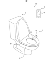
- the gas detection device 1 is installed, for example, in a flush toilet bowl 2, as shown in FIG.
- the toilet bowl 2 includes a toilet bowl 2A and a toilet seat 2B.
- the gas detection device 1 may be installed anywhere on the toilet bowl 2 .
- the gas detection device 1 may be arranged from between the toilet bowl 2A and the toilet seat 2B to the outside of the toilet 2, as shown in FIG. Part of the gas detection device 1 may be embedded in the toilet seat 2B.
- the toilet bowl 2A of the toilet bowl 2 can be discharged with feces of the subject.
- the gas detection device 1 can obtain a sample gas in which gas generated from stool discharged into the toilet bowl 2A is mixed with outside air.
- the gas detection device 1 can detect the type, concentration, etc. of the detection target gas contained in the sample gas.
- the gas detection device 1 can transmit detection results to the electronic device 3 .
- the toilet bowl 2 can be installed in a toilet room such as a house or a hospital.
- the electronic device 3 is, for example, a smart phone used by the subject.
- the electronic device 3 is not limited to a smart phone, and may be any electronic device.
- the electronic device 3 may be inside the toilet room or outside the toilet room.
- the electronic device 3 can receive the detection result from the gas detection device 1 by wireless communication or wired communication. In this case, the electronic device 3 may receive the detection result from the gas detection device 1 via the server. The electronic device 3 can display the received detection result on the display unit 3A.
- the display unit 3A may include a display capable of displaying characters and the like, and a touch screen capable of detecting contact with a user's (subject's) finger or the like.
- the display may include a display device such as a liquid crystal display (LCD), an organic electroluminescence display (OELD) or an inorganic electroluminescence display (IELD). .
- the detection method of the touch screen may be any method such as a capacitance method, a resistive film method, a surface acoustic wave method, an ultrasonic method, an infrared method, an electromagnetic induction method, or a load detection method.
- FIG. 2 is a schematic diagram showing an example of the configuration of the gas detection device 1 according to one embodiment.
- FIG. 3 is a block diagram showing an example of the configuration of the gas detection device 1.
- the gas detection device 1 is installed in the toilet bowl 2, collects a sample gas containing gas discharged from the subject's stool, and detects the type and concentration of the gas to be detected contained in the sample gas. can be detected. Further, the gas detection device 1 can transmit information indicating the type and concentration of the detected gas to be detected to the electronic device 3 as a detection result. As shown in FIGS.
- the gas detection device 1 includes a housing 10, a sampling section 21 (sample gas sampling section), a storage pump 22, a storage tank 25, a sensor chamber 23 (gas detection section), and a gas sensor group 24. , a chamber pump 26 , a discharge path 30 , a control section 40 , a subject detection section 50 , a communication section 51 and a storage section 52 .
- Housing 10 accommodates various components of the gas detection device 1 .
- Housing 10 may be constructed of any material.
- the housing 10 may be made of a material such as metal or resin.
- the collection unit 21 is a tubular member that collects a sample gas in the target space and supplies the collected sample gas into the storage tank 25 .
- the sampling part 21 is exposed to the inside of the toilet bowl 2A and has an opening 211 that opens toward the inside of the toilet bowl 2A. sample gas.
- the sampling part 21 has a sample channel for flowing the sample gas therein.
- the sample flow path is intended to be a flow path through which the collected sample gas moves.
- the sample channel communicates the opening 211 and the sensor chamber 23 .
- a reservoir pump 22 is a pump located on the sample flow path.
- the storage pump 22 may operate under the control of a pump control section 41 (described later).
- reservoir pump 22 may be a pump that operates at a constant delivery rate.
- the storage pump 22 may supply the sample gas from the sampling section 21 into the storage tank 25 .
- the storage tank 25 is located behind the storage pump 22 on the sample flow path, and temporarily stores the sample gas sampled from the sampling section 21 by the storage pump 22 .
- the function of the storage tank 25 is not limited to temporarily storing the sample gas, and may function as part of a flow path that does not store the sample gas.
- the storage tank 25 may be made of resin in the shape of a bag, or may be made of metal in the shape of a cylinder or square.
- the sensor chamber 23 is a chamber that houses the gas sensor group 24 inside. Sensor chamber 23 communicates with reservoir 25 .
- the number of gas sensors included in the gas sensor group 24 housed inside the sensor chamber 23 is not particularly limited.
- the gas sensor group 24 may include any number of gas sensors according to the types and number of gases to be detected.
- the gas sensor group 24 includes a first gas sensor 24a and a second gas sensor 24b. Both the first gas sensor 24a and the second gas sensor 24b are gas sensors capable of detecting both the first gas to be detected and the second gas to be detected. That is, the first gas sensor 24a and the second gas sensor 24b both detect the first gas to be detected and the second gas to be detected.
- the detection signal output from the first gas sensor 24a is referred to as a first detection signal.
- a detection signal output from the second gas sensor 24b is referred to as a second detection signal.
- the gas sensor group 24 may be a set of sensors that output different detection signals according to the concentration of the gas to be detected.
- a sensor constituting the gas sensor group 24 a sensor whose detection signal intensity changes according to the concentration of the gas to be detected will be described as an example, but the sensor is not limited to this.
- the sensors constituting the gas sensor group 24 can output to the signal acquisition section 42 of the control section 40 a detection signal having an intensity corresponding to the concentration of the detection target gas that can be contained in the sample gas.
- the gas detection device 1 may include multiple gas sensors. Further, the plurality of gas sensors may be capable of outputting detection signals according to concentrations of different types of detection target gases. Thereby, the gas detection device 1 can analyze the concentration of a plurality of types of detection target gases.
- Both the first gas to be detected and the second gas to be detected may be gases containing sulfur atoms in their composition formulas. Sensors that are sensitive to one type of gas that has a sulfur atom in its formula tend to be sensitive to another type of gas that has a sulfur atom in its formula. Therefore, when the sample gas contains multiple types of detection target gases that contain sulfur atoms in the composition formula, it is difficult to detect the concentration of any one of the multiple types of detection target gases with a single gas sensor. is. According to the gas detection device 1, instead of detecting individual concentrations of a plurality of types of detection target gases containing sulfur atoms in their compositional formulas, the concentrations are detected based on the first detection signal and the second detection signal, as will be described later. can be estimated with high accuracy.
- the first gas to be detected may be hydrogen sulfide.
- the second gas to be detected may be methyl mercaptan.
- Hydrogen sulfide and methyl mercaptan are gas species that are particularly difficult to detect in individual gas concentration with a single gas sensor. According to the gas detection device 1, the concentrations of hydrogen sulfide and methyl mercaptan can be accurately estimated based on the first detection signal and the second detection signal, as described later, instead of detecting individual concentrations.
- the first gas to be detected and the second gas to be detected may be gas containing a sulfur atom in its composition formula, other than hydrogen sulfide and methyl mercaptan.
- the first gas to be detected and the second gas to be detected are not limited to gases containing sulfur atoms in their compositional formulas.
- both the first gas to be detected and the second gas to be detected may be gases containing nitrogen atoms.
- the sample gas contains multiple types of detection target gases that contain nitrogen atoms in the composition formula, it is difficult to detect the concentration of any one of the multiple types of detection target gases with a single gas sensor. be.
- the gas detection device 1 instead of detecting individual concentrations of a plurality of types of detection target gases containing nitrogen atoms in their composition formulas, the concentrations are detected based on the first detection signal and the second detection signal, as will be described later. can be estimated with high accuracy.
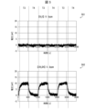
- FIG. 4 is a graph showing an example of variation in the first detection signal output from the first gas sensor 24a due to hydrogen sulfide and methyl mercaptan.
- the horizontal axis indicates time, and the vertical axis indicates the first detection signal (voltage).
- reference numeral 401 is a graph showing an example of variation in the first detection signal caused by hydrogen sulfide with a concentration of 0.3 ppm.
- reference numeral 402 is a graph showing an example of variation in the first detection signal due to methyl mercaptan having a concentration of 0.3 ppm.
- a period T1 in FIG. 4 is a period during which hydrogen sulfide or methyl mercaptan is supplied to the first gas sensor 24a.
- the first detection signal shows clear fluctuations due to hydrogen sulfide between period T1 and period T2.
- the first detection signal shows slight fluctuations due to methyl mercaptan between periods T1 and T2, but the fluctuations are small compared to the fluctuations due to hydrogen sulfide. . That is, the detection sensitivity of the first gas sensor 24a to hydrogen sulfide is greater than the detection sensitivity of the first gas sensor 24a to methyl mercaptan.
- FIG. 5 is a graph showing an example of variations in the second detection signal output from the second gas sensor 24b caused by hydrogen sulfide and methyl mercaptan.
- the horizontal axis indicates time, and the vertical axis indicates the second detection signal (voltage).
- reference numeral 501 is a graph showing an example of variations in the second detection signal caused by hydrogen sulfide with a concentration of 0.3 ppm.
- reference numeral 502 is a graph showing an example of variations in the second detection signal due to methyl mercaptan having a concentration of 0.3 ppm.
- a period T3 in FIG. 5 is a period during which hydrogen sulfide or methyl mercaptan is supplied to the second gas sensor 24b.
- the second detection signal shows clear fluctuations due to methyl mercaptan between period T3 and period T4.
- the second detection signal shows slight fluctuations caused by hydrogen sulfide between periods T3 and T4, but the fluctuations are small compared to the fluctuations caused by methyl mercaptan. . That is, the detection sensitivity of the second gas sensor 24b to methyl mercaptan is higher than the detection sensitivity of the second gas sensor 24b to hydrogen sulfide.
- the relative relationship between the detection sensitivity to hydrogen sulfide and the detection sensitivity to methyl mercaptan of the first gas sensor 24a and the second gas sensor 24b may differ from each other. Specifically, when the concentrations of hydrogen sulfide and methyl mercaptan are equal to each other, the ratio of the intensity of the first detection signal due to methyl mercaptan to the intensity of the first detection signal due to hydrogen sulfide is may be smaller than the ratio of the intensity of the second detection signal due to methyl mercaptan to the intensity of the second detection signal resulting from methyl mercaptan.
- the concentrations of hydrogen sulfide and methyl mercaptan can be accurately estimated as described later.
- the chamber pump 26 is a pump that introduces sample gas from the reservoir 25 into the sensor chamber 23 .
- the chamber pump 26 may operate under the control of a pump control section 41 (described later).
- Chamber pump 26 may be, for example, a pump that operates at a constant air delivery rate.
- the discharge amount of the chamber pump 26 may be set smaller than the discharge amount of the storage pump 22 .
- the discharge path 30 may be configured by a tubular member such as a resin tube or a metal or glass pipe.
- the exhaust channel 30 communicates the sensor chamber 23 with the outside of the housing 10 .
- the chamber pump 26 may be provided in the middle of the discharge path 30 .
- the discharge path 30 discharges the exhaust from the sensor chamber 23 to the outside of the gas detection device 1 by the operation of the chamber pump 26 .
- a portion of the discharge channel 30 may be exposed outside the toilet bowl 2A, as shown in FIG.
- control unit 40 The control unit 40 controls the operation of each unit of the gas detection device 1 and estimates the concentration of the detection target gas contained in the sample gas. As shown in FIG. 3 , the controller 40 includes a pump controller 41 , a signal acquirer 42 and an estimator 43 .
- the pump control unit 41 controls operations of the storage pump 22 and the chamber pump 26 . Specifically, the pump control unit 41 operates the storage pump 22 and the chamber pump 26 according to the detection result of the subject detection unit 50 (described later), and stops them after a predetermined time has passed. As a result, the sample gas in the toilet bowl 2A is sucked from the collection part 21 and supplied into the sensor chamber 23 via the storage tank 25 .
- the signal acquisition unit 42 acquires a detection signal corresponding to the type and concentration of the detection target gas contained in the sample gas from each gas sensor included in the gas sensor group 24 . Specifically, the signal acquisition unit 42 acquires the detection signal output from each gas sensor included in the gas sensor group 24 when the operation of the storage pump 22 and the chamber pump 26 by the pump control unit 41 is stopped. you can
- the estimation unit 43 estimates the type and concentration of the detection target gas contained in the sample gas based on the detection signal acquired by the signal acquisition unit 42 from each gas sensor included in the gas sensor group 24 .
- the detection signal acquired from each gas sensor is the detection signal output from the gas sensor.
- the estimation unit 43 estimates the concentrations of the first gas to be detected and the second gas to be detected based on the first detection signal output from the first gas sensor 24a and the second detection signal output from the second gas sensor 24b. You can As described above, both the first gas sensor 24a and the second gas sensor 24b can detect both the first gas to be detected and the second gas to be detected.
- the estimator 43 can uniquely estimate the combination of the concentration of the first gas to be detected and the concentration of the second gas to be detected that match both the first detection signal and the second detection signal.
- the estimation unit 43 may be provided in the control unit 40 of the gas detection device 1 as shown in FIG. Also, the estimation unit 43 may not be provided in the control unit 40 but may be provided on a cloud connected to the gas detection device 1 via a network. When the estimation unit 43 is provided on the cloud, the signal acquisition unit 42 may transmit the detection signal acquired from each gas sensor included in the gas sensor group 24 to the cloud via the network. The estimation unit 43 on the cloud may estimate the type and concentration of the detection target gas based on the detection signal transmitted from the signal acquisition unit 42 .
- the estimation unit 43 uses a concentration estimation model created from the first detection signal and the second detection signal for a plurality of types of teacher gases to estimate the concentrations of the first gas to be detected and the second gas to be detected contained in the sample gas. can be estimated.
- a teacher gas is a sample gas containing a first gas to be detected and a second gas to be detected whose concentrations are known.
- the concentration estimation model is created by machine learning using a set of the first detection signal and second detection signal for the teacher gas and the concentrations of the first and second target gases contained in the teacher gas. good.
- the estimating unit 43 can easily perform estimation by estimating the concentrations of the first detectable gas and the second detectable gas using such a concentration estimation model.
- the subject detection unit 50 may include at least one of an image camera (not shown), a personal identification switch, an infrared sensor, a pressure sensor, and the like.
- the subject detection unit 50 outputs the detection result to the control unit 40 .
- the subject detection unit 50 when the subject detection unit 50 includes an infrared sensor, the subject detection unit 50 detects infrared light reflected from an object irradiated by the infrared sensor, thereby detecting that the subject has entered the toilet room. can be detected. The subject detection unit 50 outputs a signal indicating that the subject has entered the toilet room to the control unit 40 as a detection result.
- the subject detection unit 50 when the subject detection unit 50 includes a pressure sensor, it detects that the subject has sat on the toilet seat 2B by detecting an increase in pressure applied to the toilet seat 2B shown in FIG. can.
- the subject detection unit 50 outputs a signal indicating that the subject has sat on the toilet seat 2B to the control unit 40 as a detection result.
- the subject detection unit 50 when the subject detection unit 50 includes a pressure sensor, it detects that the subject stands up from the toilet seat 2B by detecting a decrease in the pressure applied to the toilet seat 2B shown in FIG. can.
- the subject detection unit 50 outputs a signal indicating that the subject has stood up from the toilet seat 2B to the control unit 40 as a detection result.
- the subject detection unit 50 when the subject detection unit 50 includes an image camera, an individual identification switch, and the like, it collects data such as face images, sitting height, and weight.
- the target person detection unit 50 identifies and detects an individual from the collected data.
- the subject detection unit 50 outputs a signal indicating the identified individual to the control unit 40 as a detection result.
- the subject detection unit 50 identifies (detects) an individual based on the operation of the individual identification switch.
- personal information may be registered (stored) in advance in the storage unit 52 .
- the target person detection unit 50 outputs a signal indicating the specified individual to the control unit 40 as a detection result.
- the subject detection unit 50 may detect that the subject has defecated.
- the subject detection unit 50 outputs a signal indicating that the subject has defecated to the control unit 40 as a detection result.
- the communication unit 51 communicates with the electronic device 3 to present the analysis result of the gas to be detected by the control unit 40 to the subject by, for example, display on the display unit 3A or voice.
- the communication unit 51 may be capable of communicating with an external server.
- the communication method used for communication between the communication unit 51 and the electronic device 3 and the external server may be a short-range wireless communication standard, a wireless communication standard for connecting to a mobile phone network, or a wired communication standard.
- Near field communication standards may include, for example, WiFi (registered trademark), Bluetooth (registered trademark), infrared rays, and Near Field Communication (NFC).
- a wireless communication standard for connecting to a mobile phone network may include, for example, LTE (Long Term Evolution) or a mobile communication system of fourth generation or higher.
- the communication method used for communication between the communication unit 51 and the electronic device 3 and the external server may be a communication standard such as LPWA (Low Power Wide Area) or LPWAN (Low Power Wide Area Network).
- the storage unit 52 is composed of, for example, a semiconductor memory, a magnetic memory, or the like.
- the storage unit 52 stores various information and programs for operating the gas detection device 1 .
- the storage unit 52 may function as a work memory.
- the storage unit 52 may also store, for example, a concentration estimation model for the estimation unit 43 to estimate the concentration of the first detection gas and the second detection gas.
- the gas detection device 1 may include a sampling section 21 , a storage pump 22 , a storage tank 25 , a sensor chamber 23 , a gas sensor group 24 , a chamber pump 26 and a control section 40 .
- the gas sensor group 24 may include a first gas sensor 24a and a second gas sensor 24b.
- the control unit 40 may include an estimation unit 43 .
- the concentration of the detection target gas contained in the sample gas is detected by the gas sensor group 24 including the first gas sensor 24a and the second gas sensor 24b.
- Both the first gas sensor 24a and the second gas sensor 24b may be gas sensors capable of detecting both the first gas to be detected and the second gas to be detected.
- the estimation unit 43 estimates the concentrations of the first gas to be detected and the second gas to be detected.
- the gas detection device 1 can highly accurately estimate the concentration of a gas whose concentration is difficult to measure accurately with a single sensor.
- both the first gas sensor 24a and the second gas sensor 24b may be electrochemical sensors.
- electrochemical sensors By using electrochemical sensors as the first gas sensor 24a and the second gas sensor 24b, the concentrations of the first gas to be detected and the second gas to be detected can be detected with high sensitivity.
- the first gas sensor 24a and the second gas sensor 24b are not limited to electrochemical sensors. Semiconductor) type sensor, sensitive film type sensor, optical sensor, photoacoustic sensor, or the like. As the sensitive film type sensor, a sensitive film stress type sensor or a sensitive film resonance type sensor may be used.
- the gas sensor group 24 may include multiple types of sensors. The first gas sensor 24a and the second gas sensor 24b may be selected according to the first gas to be detected and the second gas to be detected.
- FIG. 6 is a partial cross-sectional view showing an example of the configuration of the first gas sensor 24a included in the gas sensor group 24.
- the first gas sensor 24a may include a case 241, a first electrode 244, a second electrode 245, and electrode pins 246.
- the first gas sensor 24a may include a case 241, a first electrode 244, a second electrode 245, and electrode pins 246.
- the case 241 is a housing that accommodates the first electrode 244 (electrode), the second electrode 245 (electrode), and the electrolytic solution. There may be a reference electrode between the first electrode 244 and the second electrode 245 .
- a vent hole 242 is formed in the case 241 for taking in the sample gas.
- a pre-filter 243 may be provided in the ventilation hole 242 to reduce foreign matter such as dust from entering the case 241 .
- the first electrode 244 and the second electrode 245 may be arranged at positions facing each other within the case 241, for example.
- the first electrode 244 may be arranged on the vent hole 242 side, for example.
- the second electrode 245 may be installed, for example, on the side facing the first electrode 244 within the case 241 . Also, when the first electrode 244 and the second electrode 245 are adjacent to each other, a non-woven fabric may be placed between them.
- the first electrode 244 and the second electrode 245 are electrically connected to each other through the electrolytic solution.
- the first electrode 244, the second electrode 245, and the electrolyte constitute an electrode unit that outputs a signal corresponding to the concentration of the detection target gas contained in the sample gas.
- the first electrode 244 and the second electrode 245 may be carbon-based electrodes.
- the electrolytic solution may contain, for example, sulfuric acid as a main component, but is not limited to this.
- the resistance value between the first electrode 244 and the second electrode 245 changes.
- the degree of change in resistance varies depending on the type and concentration of gas contained in the sample gas.
- the voltage between the first electrode 244 and the second electrode 245 changes according to the type and concentration of gas contained in the sample gas.
- a change in the voltage becomes a signal indicating the type and concentration of the gas contained in the sample gas.
- the electrode pin 246 is a pin for extracting signals output from the first electrode 244 and the second electrode 245 to the outside.
- the first gas sensor 24 a may comprise an electrode pin 246 connected to the first electrode 244 and an electrode pin 246 connected to the second electrode 245 .
- the electrode pin 246 may be made of platinum, for example, but is not limited to this.
- FIG. 7 is a schematic diagram showing an example of the configuration of the gas detection device 1A according to the third embodiment. As shown in FIG. 7, the gas detection device 1A differs from the gas detection device 1 only in that the gas sensor group 24 further includes a third gas sensor 24c.
- the third gas sensor 24c is a gas sensor capable of detecting the first gas to be detected and the second gas to be detected.
- the detection sensitivity of the third gas sensor 24c to the first detectable gas may be different from both the detection sensitivity of the first gas sensor 24a to the first detectable gas and the detection sensitivity of the second gas sensor 24b to the first detectable gas.
- the gas detection device 1A can obtain three types of detection signals for the first gas to be detected and the second gas to be detected. Therefore, the concentrations of the first gas to be detected and the second gas to be detected can be estimated with higher accuracy.
- the gas species of the first gas to be detected and the second gas to be detected are different from those in the first embodiment.
- the first gas to be detected may be hydrogen sulfide or methyl mercaptan.
- the second gas to be detected may be hydrogen, water, ammonia, or alcohol.
- the second gas to be detected is a gas that causes noise or interferes with the output signal from the gas sensor that detects the first gas to be detected. That is, the concentration of the second gas to be detected affects the detection signal from the gas sensor that detects the first gas to be detected. Therefore, in an environment where the second gas to be detected exists, it is difficult to detect the concentration of the first gas to be detected with a single gas sensor.
- the intensity of the second detection signal caused by the first gas to be detected is compared with the intensity of the second detection signal caused by the first gas to be detected.
- the ratio of the strengths of the two detected signals may be greater than one.
- a second detection signal resulting from the second detection gas relative to the intensity of the second detection signal resulting from the first detection gas when the concentrations of the first detection gas and the second detection gas are substantially equal to each other; may be greater than ten. That is, the second gas sensor 24b may be a gas sensor that mainly detects the second gas to be detected.
- the estimation unit 43 can accurately estimate the concentration of the second gas to be detected based on the second detection signal. That is, the estimation unit 43 can also accurately estimate the magnitude of the influence of the concentration of the second gas to be detected on the first detection signal. Therefore, the estimator 43 can accurately estimate the concentration of the first gas to be detected based on the first detection signal.
- the second detection signal output from the second gas sensor 24b has little effect on the estimation of the concentration of the first gas to be detected.
- such a second detection signal is not used as an explanatory variable in the concentration estimation model of the first gas to be detected.
- the second detection signal may also be used as an explanatory variable in the concentration estimation model of the first detected gas.
- the second detection signal may also be used as an explanatory variable in the model for estimating the concentration of the first gas to be detected.
- FIG. 8 is a schematic diagram showing an example of the configuration of the gas detection device 1B according to the fifth embodiment.
- the gas detection device 1B differs from the gas detection device 1 in that the sensor chamber 23 is positioned downstream of the chamber pump 26.
- the concentration of a gas whose concentration is difficult to accurately measure with a single sensor can be estimated with high accuracy.
- the functions of the gas detection devices 1, 1A, and 1B are programs for causing a computer to function as the apparatus, and each control block of the apparatus (especially each part included in the control unit 40). ) can be implemented by a program for causing a computer to function.
- the device comprises a computer having at least one control device (eg processor) and at least one storage device (eg memory) as hardware for executing the program.
- control device eg processor
- storage device eg memory
- the above program may be recorded on one or more computer-readable recording media, not temporary.
- the recording medium may or may not be included in the device.
- the program may be supplied to the device via any transmission medium, wired or wireless.
- part or all of the functions of the above control blocks can be realized by logic circuits.
- an integrated circuit in which logic circuits functioning as the above control blocks are formed is also included in the scope of the present disclosure.
- each process described in each of the above embodiments may be executed by AI (Artificial Intelligence).
- AI Artificial Intelligence
- the AI may operate on the control device, or may operate on another device (for example, an edge computer or a cloud server).
Abstract
サンプルガスに含まれる成分の濃度を精度良く検出する。ガス検出装置は、採取部と、第1ガスセンサおよび第2ガスセンサと、を備える。採取部は、第1被検出ガスおよび第2被検出ガスを含むサンプルガスを採取する。第1ガスセンサおよび第2ガスセンサは、第1被検出ガスおよび第2被検出ガスの双方を検出可能なセンサである。第1ガスセンサと第2ガスセンサとは、第1被検出ガスに対する検出感度と第2被検出ガスに対する検出感度との相対的関係が互いに異なる。
Description
本開示は、ガスの濃度を検出するガス検出装置、および当該ガス検出装置を備えるガス検出システムに関する。
被検者が排出した便から発生する臭気性ガスを検出するシステムが知られている(例えば、特許文献1)。
本開示の一態様に係るガス検出装置は、第1被検出ガスおよび第2被検出ガスを含むサンプルガスを採取するサンプルガス採取部と、前記サンプルガスに含まれる前記第1被検出ガスおよび前記第2被検出ガスの双方を検出可能な、第1ガスセンサおよび第2ガスセンサを含む複数のガスセンサを備えるガス検出部と、を備え、前記第1ガスセンサと前記第2ガスセンサとは、前記第1被検出ガスに対する検出感度と前記第2被検出ガスに対する検出感度との相対的関係が互いに異なる。
〔実施形態1〕
以下、本開示の一実施形態について、詳細に説明する。
以下、本開示の一実施形態について、詳細に説明する。
<分析システム100>
図1は、本開示の一実施形態に係る分析システム100の構成の一例を示す外観図である。本明細書において参照する各図は、説明の便宜上、実施形態を説明するために一部の部材のみを簡略化して示した模式図である。従って、分析システム100は、本明細書が参照する各図に示されていない任意の構成部材を備え得る。また、各図中の部材の寸法は、実際の構成部材の寸法および各部材の寸法比率などを忠実に表したものではない。
図1は、本開示の一実施形態に係る分析システム100の構成の一例を示す外観図である。本明細書において参照する各図は、説明の便宜上、実施形態を説明するために一部の部材のみを簡略化して示した模式図である。従って、分析システム100は、本明細書が参照する各図に示されていない任意の構成部材を備え得る。また、各図中の部材の寸法は、実際の構成部材の寸法および各部材の寸法比率などを忠実に表したものではない。
図1に示すような分析システム100は、「ガス検出システム」、あるいは「ガス分析システム」と呼称され得る。図1に示すように、分析システム100は、ガス検出装置1、および電子機器(端末装置)3を備える。また、ガス検出装置1は、被検者の検体から発生したガスを検出する。検出されたガスは被検者の健康状態の分析等に用いられ得る。ここで、被検者の検体は、例えば被検者の組織の一部または尿等であり得るが、本実施形態においては被検者の便である。ガス検出装置1が備える、後述するガスセンサ群24によって検出される対象となる化学物質であり、かつ、気体として存在可能な化学物質を「検出対象ガス」と称する。検出対象ガスは、1種類であってもよいし、複数種類であってもよい。検出対象ガスは、例えば、被検者の便から排出されるガス(サンプルガス)に含まれ得る。検出対象ガスの濃度とは、検出される対象となる化学物質のサンプルガス中における濃度を意図している。
ガス検出装置1は、図1に示すように、例えば水洗の便器2に設置される。便器2は、便器ボウル2Aと、便座2Bとを備える。ガス検出装置1は、便器2の任意の箇所に設置されてよい。一例として、ガス検出装置1は、図1に示すように、便器ボウル2Aと便座2Bとの間から便器2の外部にわたって配置されてよい。ガス検出装置1の一部は、便座2Bに埋め込まれていてよい。便器2の便器ボウル2Aには、被検者の便が排出され得る。ガス検出装置1は、便器ボウル2Aに排出された便から発生するガスが外気と混成されたサンプルガスを取得し得る。ガス検出装置1は、サンプルガスに含まれる検出対象ガスの種類および濃度等を検出し得る。ガス検出装置1は、検出結果を電子機器3に送信し得る。
便器2は、住宅または病院等のトイレ室に設置され得る。また、電子機器3は、例えば、被検者が利用するスマートフォンである。ただし、電子機器3は、スマートフォンに限定されず、任意の電子機器であってもよい。電子機器3は、トイレ室の内部にあってもよいし、トイレ室の外部にあってもよい。
電子機器3は、ガス検出装置1から検出結果を、無線通信または有線通信によって、受信し得る。この場合、電子機器3は、サーバを経由してガス検出装置1から検出結果を受信してもよい。電子機器3は、受信した検出結果を、表示部3Aに表示し得る。表示部3Aは、文字等を表示可能なディスプレイと、ユーザ(被検者)の指等の接触を検出可能なタッチスクリーンとを含んで構成されてよい。当該ディスプレイは、液晶ディスプレイ(LCD:Liquid Crystal Display)、有機ELディスプレイ(OELD:Organic Electro‐Luminescence Display)または無機ELディスプレイ(IELD:Inorganic Electro‐Luminescence Display)等の表示デバイスを含んで構成されてよい。当該タッチスクリーンの検出方式は、静電容量方式、抵抗膜方式、表面弾性波方式、超音波方式、赤外線方式、電磁誘導方式または荷重検出方式等の任意の方式でよい。
<ガス検出装置1>
図2は、一実施形態に係るガス検出装置1の構成の一例を示す概略図である。図3は、ガス検出装置1の構成の一例を示すブロック図である。上述したように、ガス検出装置1は、便器2に設置され、被検者の便から排出されたガスを含むサンプルガスを採取し、当該サンプルガスに含まれる検出対象ガスの種類および濃度等を検出し得る。また、ガス検出装置1は、検出した検出対象ガスの種類および濃度等を示す情報を、検出結果として電子機器3に送信し得る。図2および図3に示すように、ガス検出装置1は、筐体10、採取部21(サンプルガス採取部)、貯留ポンプ22、貯留槽25、センサチャンバ23(ガス検出部)、ガスセンサ群24、チャンバポンプ26、排出路30、制御部40、対象者検知部50、通信部51、および記憶部52を備える。
図2は、一実施形態に係るガス検出装置1の構成の一例を示す概略図である。図3は、ガス検出装置1の構成の一例を示すブロック図である。上述したように、ガス検出装置1は、便器2に設置され、被検者の便から排出されたガスを含むサンプルガスを採取し、当該サンプルガスに含まれる検出対象ガスの種類および濃度等を検出し得る。また、ガス検出装置1は、検出した検出対象ガスの種類および濃度等を示す情報を、検出結果として電子機器3に送信し得る。図2および図3に示すように、ガス検出装置1は、筐体10、採取部21(サンプルガス採取部)、貯留ポンプ22、貯留槽25、センサチャンバ23(ガス検出部)、ガスセンサ群24、チャンバポンプ26、排出路30、制御部40、対象者検知部50、通信部51、および記憶部52を備える。
(筐体10)
筐体10は、ガス検出装置1の各種部品を収容する。筐体10は、任意の材料で構成されてよい。例えば、筐体10は、金属または樹脂等の材料で構成されてよい。
筐体10は、ガス検出装置1の各種部品を収容する。筐体10は、任意の材料で構成されてよい。例えば、筐体10は、金属または樹脂等の材料で構成されてよい。
[採取部21]
採取部21は、対象空間内のサンプルガスを採取し、貯留槽25内に、採取された当該サンプルガスを供給する管状の部材である。採取部21は、便器ボウル2Aの内側に露出し、便器ボウル2A内に向けて開口する開口部211を有しており、貯留ポンプ22(後述)の動作により、対象空間としての便器ボウル2A内のサンプルガスを採取する。また、採取部21は、サンプルガスを流すためのサンプル流路を内部に有している。ここで、サンプル流路とは、採取されたサンプルガスが移動する流路を意図している。サンプル流路は、開口部211とセンサチャンバ23とを連通させる。
採取部21は、対象空間内のサンプルガスを採取し、貯留槽25内に、採取された当該サンプルガスを供給する管状の部材である。採取部21は、便器ボウル2Aの内側に露出し、便器ボウル2A内に向けて開口する開口部211を有しており、貯留ポンプ22(後述)の動作により、対象空間としての便器ボウル2A内のサンプルガスを採取する。また、採取部21は、サンプルガスを流すためのサンプル流路を内部に有している。ここで、サンプル流路とは、採取されたサンプルガスが移動する流路を意図している。サンプル流路は、開口部211とセンサチャンバ23とを連通させる。
[貯留ポンプ22]
貯留ポンプ22は、サンプル流路上に位置しているポンプである。貯留ポンプ22は、ポンプ制御部41(後述)の制御に従って動作してよい。一例として、貯留ポンプ22は、一定の送気速度で動作するポンプであってよい。貯留ポンプ22は、採取部21から貯留槽25内にサンプルガスを供給してよい。
貯留ポンプ22は、サンプル流路上に位置しているポンプである。貯留ポンプ22は、ポンプ制御部41(後述)の制御に従って動作してよい。一例として、貯留ポンプ22は、一定の送気速度で動作するポンプであってよい。貯留ポンプ22は、採取部21から貯留槽25内にサンプルガスを供給してよい。
[貯留槽25]
貯留槽25は、サンプル流路上では貯留ポンプ22の後方にあり、採取部21から貯留ポンプ22によって採取されたサンプルガスを一時的に貯留する。ただし、貯留槽25の機能は、サンプルガスを一時的に貯留することに限定されず、サンプルガスを貯留しない流路の一部として機能してもよい。貯留槽25は、樹脂により袋状に形成されていてもよいし、金属により筒状または角型に形成されていてもよい。
貯留槽25は、サンプル流路上では貯留ポンプ22の後方にあり、採取部21から貯留ポンプ22によって採取されたサンプルガスを一時的に貯留する。ただし、貯留槽25の機能は、サンプルガスを一時的に貯留することに限定されず、サンプルガスを貯留しない流路の一部として機能してもよい。貯留槽25は、樹脂により袋状に形成されていてもよいし、金属により筒状または角型に形成されていてもよい。
[センサチャンバ23]
センサチャンバ23は、ガスセンサ群24を内部に格納するチャンバである。センサチャンバ23は、貯留槽25と連通している。センサチャンバ23が内部に格納するガスセンサ群24に含まれるガスセンサの数は特に制限されない。ガスセンサ群24は、検出対象ガスの種類および数に応じて任意の数のガスセンサを含んでいてよい。
センサチャンバ23は、ガスセンサ群24を内部に格納するチャンバである。センサチャンバ23は、貯留槽25と連通している。センサチャンバ23が内部に格納するガスセンサ群24に含まれるガスセンサの数は特に制限されない。ガスセンサ群24は、検出対象ガスの種類および数に応じて任意の数のガスセンサを含んでいてよい。
[ガスセンサ群24]
ガスセンサ群24は、第1ガスセンサ24aおよび第2ガスセンサ24bを含んでいる。第1ガスセンサ24aおよび第2ガスセンサ24bは、いずれも第1被検出ガスおよび第2被検出ガスの双方を検出可能なガスセンサである。すなわち、第1ガスセンサ24aおよび第2ガスセンサ24bは、いずれも第1被検出ガスおよび第2被検出ガスを検出対象ガスとする。以下では、第1ガスセンサ24aから出力される検出信号を、第1検出信号と称する。また、第2ガスセンサ24bから出力される検出信号を、第2検出信号と称する。
ガスセンサ群24は、第1ガスセンサ24aおよび第2ガスセンサ24bを含んでいる。第1ガスセンサ24aおよび第2ガスセンサ24bは、いずれも第1被検出ガスおよび第2被検出ガスの双方を検出可能なガスセンサである。すなわち、第1ガスセンサ24aおよび第2ガスセンサ24bは、いずれも第1被検出ガスおよび第2被検出ガスを検出対象ガスとする。以下では、第1ガスセンサ24aから出力される検出信号を、第1検出信号と称する。また、第2ガスセンサ24bから出力される検出信号を、第2検出信号と称する。
ガスセンサ群24は、検出対象ガスの濃度に応じて異なる検出信号を出力するセンサの集合であればよい。以下では、ガスセンサ群24を構成するセンサとして、検出対象ガスの濃度に応じて検出信号の強度が変化するセンサを例に挙げて説明するが、これに限定されない。一例として、ガスセンサ群24を構成するセンサは、サンプルガスに含まれ得る検出対象ガスの濃度に応じた強度の検出信号を制御部40の信号取得部42に出力可能である。図2に示すように、ガス検出装置1には、複数のガスセンサが含まれていてよい。また、複数のガスセンサは、それぞれ異なる種類の検出対象ガスの濃度に応じた検出信号を出力可能であってもよい。これにより、ガス検出装置1は、複数種類の検出対象ガスの濃度を分析することができる。
第1被検出ガスおよび第2被検出ガスは、いずれも組成式中に硫黄原子を含むガスであってよい。組成式中に硫黄原子を含む、ある種類のガスに対して感度を有するセンサは、組成式中に硫黄原子を含む、別の種類のガスに対しても感度を有する傾向がある。このため、組成式中に硫黄原子を含む、複数種類の検出対象ガスをサンプルガスが含む場合、当該複数種類の検出対象ガスのうちいずれかの濃度を、単一のガスセンサによって検出することは困難である。ガス検出装置1によれば、組成式中に硫黄原子を含む複数種類の検出対象ガスについて、個々の濃度を検出する代わりに、後述するとおり、第1検出信号および第2検出信号に基づいて濃度を精度よく推定できる。
具体的には、第1被検出ガスは、硫化水素であってよい。また、第2被検出ガスは、メチルメルカプタンであってよい。硫化水素およびメチルメルカプタンは、単一のガスセンサによって個々のガスの濃度を検出することが特に困難なガス種である。ガス検出装置1によれば、硫化水素およびメチルメルカプタンについて、個々の濃度を検出する代わりに、後述するとおり、第1検出信号および第2検出信号に基づいて濃度を精度よく推定できる。ただし、第1被検出ガスおよび第2被検出ガスは、硫化水素およびメチルメルカプタンとは別の、組成式中に硫黄原子を含むガスであってもよい。
また、第1被検出ガスおよび第2被検出ガスは、組成式中に硫黄原子を含むガスに限定されない。例えば第1被検出ガスおよび第2被検出ガスは、いずれも窒素原子を含むガスであってもよい。組成式中に窒素原子を含む、複数種類の検出対象ガスをサンプルガスが含む場合にも、当該複数種類の検出対象ガスのうちいずれかの濃度を、単一のガスセンサによって検出することは困難である。ガス検出装置1によれば、組成式中に窒素原子を含む複数種類の検出対象ガスについて、個々の濃度を検出する代わりに、後述するとおり、第1検出信号および第2検出信号に基づいて濃度を精度よく推定できる。
図4は、第1ガスセンサ24aから出力される第1検出信号の、硫化水素およびメチルメルカプタンに起因する変動の例を示すグラフである。図4において、横軸は時間を示し、縦軸は第1検出信号(電圧)を示す。図4において、符号401は、濃度が0.3ppmである硫化水素に起因する第1検出信号の変動の例を示すグラフである。図4において、符号402は、濃度が0.3ppmであるメチルメルカプタンに起因する第1検出信号の変動の例を示すグラフである。図4における期間T1は、硫化水素またはメチルメルカプタンを第1ガスセンサ24aに供給していた期間である。また、図4における期間T2は、硫化水素またはメチルメルカプタンの第1ガスセンサ24aへの供給を停止し、それまでに供給していた硫化水素またはメチルメルカプタンを、例えば、外部の空気または窒素などを用いて除去していた期間である。
図4の符号401に示すように、第1検出信号には、期間T1と期間T2とで、硫化水素に起因する明確な変動がみられる。一方で、図4の符号402に示すように、第1検出信号には、期間T1と期間T2とで、メチルメルカプタンに起因する変動は若干見られるものの、硫化水素に起因する変動と比較すると小さい。すなわち、第1ガスセンサ24aの硫化水素に対する検出感度は、第1ガスセンサ24aのメチルメルカプタンに対する検出感度に対する検出感度よりも大きい。
図5は、第2ガスセンサ24bから出力される第2検出信号の、硫化水素およびメチルメルカプタンに起因する変動の例を示すグラフである。図5において、横軸は時間を示し、縦軸は第2検出信号(電圧)を示す。図5において、符号501は、濃度が0.3ppmである硫化水素に起因する第2検出信号の変動の例を示すグラフである。図5において、符号502は、濃度が0.3ppmであるメチルメルカプタンに起因する第2検出信号の変動の例を示すグラフである。図5における期間T3は、硫化水素またはメチルメルカプタンを第2ガスセンサ24bに供給していた期間である。また、図5における期間T4は、硫化水素またはメチルメルカプタンの第1ガスセンサ24aへの供給を停止し、それまでに供給していた硫化水素またはメチルメルカプタンを、例えば、外部の空気または窒素などを用いて除去していた期間である。
図5の符号502に示すように、第2検出信号には、期間T3と期間T4とで、メチルメルカプタンに起因する明確な変動がみられる。一方で、図5の符号501に示すように、第2検出信号には、期間T3と期間T4とで、硫化水素に起因する変動は若干見られるものの、メチルメルカプタンに起因する変動と比較すると小さい。すなわち、第2ガスセンサ24bのメチルメルカプタンに対する検出感度は、第2ガスセンサ24bの硫化水素に対する検出感度よりも大きい。
図4および図5に示したように、第1ガスセンサ24aおよび第2ガスセンサ24bの、硫化水素に対する検出感度とメチルメルカプタンに対する検出感度との相対的関係は、互いに異なっていてよい。具体的には、硫化水素およびメチルメルカプタンの濃度が互いに等しい場合において、硫化水素に起因する第1検出信号の強度に対する、メチルメルカプタンに起因する第1検出信号の強度の比率は、硫化水素に起因する第2検出信号の強度に対する、メチルメルカプタンに起因する前記第2検出信号の強度の比率よりも小さくてよい。このような第1ガスセンサ24aおよび第2ガスセンサ24bをガスセンサ群24が含むことにより、後述するとおり、硫化水素およびメチルメルカプタンの濃度を精度よく推定することができる。
[チャンバポンプ26]
チャンバポンプ26は、サンプルガスを貯留槽25からセンサチャンバ23に導入するポンプである。チャンバポンプ26は、ポンプ制御部41(後述)の制御に従って動作してよい。チャンバポンプ26は、例えば、一定の送気速度で動作するポンプであってよい。また、チャンバポンプ26の吐出量は、貯留ポンプ22の吐出量よりも小さく設定されていてよい。
チャンバポンプ26は、サンプルガスを貯留槽25からセンサチャンバ23に導入するポンプである。チャンバポンプ26は、ポンプ制御部41(後述)の制御に従って動作してよい。チャンバポンプ26は、例えば、一定の送気速度で動作するポンプであってよい。また、チャンバポンプ26の吐出量は、貯留ポンプ22の吐出量よりも小さく設定されていてよい。
(排出路30)
排出路30は、樹脂製チューブ或いは金属製またはガラス製配管等の管状の部材で構成されてよい。排出路30は、センサチャンバ23を筐体10の外部と連通させる。チャンバポンプ26は、排出路30の途中に設けられていてよい。排出路30は、チャンバポンプ26の動作により、センサチャンバ23からの排気をガス検出装置1の外部に排出する。排出路30の一部は、図1に示すように、便器ボウル2Aの外側へ露出し得る。
排出路30は、樹脂製チューブ或いは金属製またはガラス製配管等の管状の部材で構成されてよい。排出路30は、センサチャンバ23を筐体10の外部と連通させる。チャンバポンプ26は、排出路30の途中に設けられていてよい。排出路30は、チャンバポンプ26の動作により、センサチャンバ23からの排気をガス検出装置1の外部に排出する。排出路30の一部は、図1に示すように、便器ボウル2Aの外側へ露出し得る。
(制御部40)
制御部40は、ガス検出装置1の各部の動作を制御し、サンプルガスに含まれる検出対象ガスの濃度の推定を行う。図3に示すように、制御部40は、ポンプ制御部41、信号取得部42および推定部43を備える。
制御部40は、ガス検出装置1の各部の動作を制御し、サンプルガスに含まれる検出対象ガスの濃度の推定を行う。図3に示すように、制御部40は、ポンプ制御部41、信号取得部42および推定部43を備える。
[ポンプ制御部41]
ポンプ制御部41は、貯留ポンプ22およびチャンバポンプ26の動作を制御する。具体的には、ポンプ制御部41は、対象者検知部50(後述)の検知結果に応じて貯留ポンプ22およびチャンバポンプ26を動作させ、所定時間が経過した後に停止させる。これにより、採取部21から便器ボウル2A内のサンプルガスが吸引され、貯留槽25を経由してセンサチャンバ23内に供給される。
ポンプ制御部41は、貯留ポンプ22およびチャンバポンプ26の動作を制御する。具体的には、ポンプ制御部41は、対象者検知部50(後述)の検知結果に応じて貯留ポンプ22およびチャンバポンプ26を動作させ、所定時間が経過した後に停止させる。これにより、採取部21から便器ボウル2A内のサンプルガスが吸引され、貯留槽25を経由してセンサチャンバ23内に供給される。
[信号取得部42]
信号取得部42は、サンプルガスに含まれる検出対象ガスの種類および濃度に応じた検出信号をガスセンサ群24に含まれる各ガスセンサから取得する。具体的には、信号取得部42は、ポンプ制御部41による貯留ポンプ22およびチャンバポンプ26の動作が停止することを契機として、ガスセンサ群24に含まれる各ガスセンサから出力される検出信号を取得してよい。
信号取得部42は、サンプルガスに含まれる検出対象ガスの種類および濃度に応じた検出信号をガスセンサ群24に含まれる各ガスセンサから取得する。具体的には、信号取得部42は、ポンプ制御部41による貯留ポンプ22およびチャンバポンプ26の動作が停止することを契機として、ガスセンサ群24に含まれる各ガスセンサから出力される検出信号を取得してよい。
[推定部43]
推定部43は、信号取得部42がガスセンサ群24に含まれる各ガスセンサから取得した検出信号に基づいて、サンプルガスに含まれる検出対象ガスの種類および濃度を推定する。各ガスセンサから取得した検出信号とは、すなわちガスセンサから出力された検出信号である。推定部43は、第1ガスセンサ24aから出力される第1検出信号、および第2ガスセンサ24bから出力される第2検出信号に基づいて、第1被検出ガスおよび第2被検出ガスの濃度を推定してよい。上述したとおり、第1ガスセンサ24aおよび第2ガスセンサ24bは、いずれも第1被検出ガスおよび第2被検出ガスの双方を検出可能である。このため、第1検出信号および第2検出信号のいずれか一方のみに基づいては、第1被検出ガスおよび第2被検出ガスの濃度の組み合わせを一意に推定できない。上述したとおり、第1ガスセンサ24aと第2ガスセンサ24bとは、第1被検出ガスに対する検出感度と第2被検出ガスに対する検出感度との相対的関係が互いに異なる。このため、推定部43は、第1検出信号および第2検出信号の両方に整合する第1被検出ガスの濃度および第2被検出ガスの濃度の組み合わせを一意に推定できる。
推定部43は、信号取得部42がガスセンサ群24に含まれる各ガスセンサから取得した検出信号に基づいて、サンプルガスに含まれる検出対象ガスの種類および濃度を推定する。各ガスセンサから取得した検出信号とは、すなわちガスセンサから出力された検出信号である。推定部43は、第1ガスセンサ24aから出力される第1検出信号、および第2ガスセンサ24bから出力される第2検出信号に基づいて、第1被検出ガスおよび第2被検出ガスの濃度を推定してよい。上述したとおり、第1ガスセンサ24aおよび第2ガスセンサ24bは、いずれも第1被検出ガスおよび第2被検出ガスの双方を検出可能である。このため、第1検出信号および第2検出信号のいずれか一方のみに基づいては、第1被検出ガスおよび第2被検出ガスの濃度の組み合わせを一意に推定できない。上述したとおり、第1ガスセンサ24aと第2ガスセンサ24bとは、第1被検出ガスに対する検出感度と第2被検出ガスに対する検出感度との相対的関係が互いに異なる。このため、推定部43は、第1検出信号および第2検出信号の両方に整合する第1被検出ガスの濃度および第2被検出ガスの濃度の組み合わせを一意に推定できる。
推定部43は、図3に示したように、ガス検出装置1の制御部40に備えられていてもよい。また、推定部43は、制御部40には備えられず、ネットワークを介してガス検出装置1と接続されたクラウド上に備えられていてもよい。推定部43がクラウド上に備えられる場合、信号取得部42は、ガスセンサ群24に含まれる各ガスセンサから取得した検出信号を、ネットワークを介してクラウドに送信してよい。クラウド上の推定部43は、信号取得部42から送信された検出信号に基づいて、検出対象ガスの種類および濃度を推定してよい。
推定部43は、複数種類の教師ガスについての第1検出信号および第2検出信号から作成された濃度推定モデルを用いて、サンプルガスに含まれる第1被検出ガスおよび第2被検出ガスの濃度を推定してよい。教師ガスとは、濃度が既知である第1被検出ガスおよび第2被検出ガスを含むサンプルガスである。濃度推定モデルは、教師ガスについての第1検出信号および第2検出信号と、教師ガスに含まれる第1被検出ガスおよび第2被検出ガスの濃度との組を用いた機械学習により作成されてよい。推定部43は、このような濃度推定モデルを用いて第1被検出ガスおよび第2被検出ガスの濃度を推定することで、簡易に推定を行うことができる。
(対象者検知部50)
対象者検知部50は、不図示の画像カメラ、個人識別スイッチ、赤外線センサおよび圧力センサ等の少なくとも何れかを含んで構成されていてよい。対象者検知部50は、検出結果を、制御部40に出力する。
対象者検知部50は、不図示の画像カメラ、個人識別スイッチ、赤外線センサおよび圧力センサ等の少なくとも何れかを含んで構成されていてよい。対象者検知部50は、検出結果を、制御部40に出力する。
例えば、対象者検知部50は、赤外線センサを含んで構成される場合には、赤外線センサが照射した赤外線の対象物からの反射光を検出することにより、被検者がトイレ室に入室したことを検出し得る。対象者検知部50は、検出結果として、被検者がトイレ室に入室したことを示す信号を制御部40に出力する。
例えば、対象者検知部50は、圧力センサを含んで構成される場合には、図1に示す便座2Bにかかる圧力の上昇を検出することにより、被検者が便座2Bに座ったことを検出し得る。対象者検知部50は、検出結果として、被検者が便座2Bに座ったことを示す信号を制御部40に出力する。
例えば、対象者検知部50は、圧力センサを含んで構成される場合には、図1に示す便座2Bにかかる圧力の低下を検出することにより、被検者が便座2Bから立ち上がったことを検出し得る。対象者検知部50は、検出結果として、被検者が便座2Bから立ち上がったことを示す信号を制御部40に出力する。
例えば、対象者検知部50は、画像カメラおよび個人識別スイッチ等を含んで構成される場合には、顔画像、座高および体重等のデータを収集する。対象者検知部50は、収集したデータから個人を特定識別して検出する。対象者検知部50は、検出結果として、特定識別した個人を示す信号を制御部40に出力する。
例えば、対象者検知部50は、個人識別スイッチ等を含んで構成される場合には、個人識別スイッチの操作に基づいて、個人を特定(検出)する。この場合、記憶部52には、予め個人情報が登録(記憶)されてよい。対象者検知部50は、検出結果として、特定した個人を示す信号を制御部40に出力する。
また、対象者検知部50は、被検者が排便したことを検知してもよい。対象者検知部50は、検出結果として、被検者が排便したことを示す信号を制御部40に出力する。
(通信部51)
通信部51は、制御部40による検出対象ガスの分析結果を、例えば表示部3Aへの表示または音声によって被検者に示す電子機器3と通信する。通信部51は、外部サーバと通信可能であってもよい。通信部51と電子機器3および外部サーバとの通信において用いられる通信方式は、近距離無線通信規格または携帯電話網へ接続する無線通信規格であってもよいし、有線通信規格であってもよい。近距離無線通信規格は、例えば、WiFi(登録商標)、Bluetooth(登録商標)、赤外線およびNFC(Near Field Communication)等を含んでよい。携帯電話網へ接続する無線通信規格は、例えば、LTE(Long Term Evolution)または第4世代以上の移動通信システム等を含んでよい。また、通信部51と電子機器3および外部サーバとの通信において用いられる通信方式は、例えばLPWA(Low Power Wide Area)またはLPWAN(Low Power Wide Area Network)等の通信規格でよい。
通信部51は、制御部40による検出対象ガスの分析結果を、例えば表示部3Aへの表示または音声によって被検者に示す電子機器3と通信する。通信部51は、外部サーバと通信可能であってもよい。通信部51と電子機器3および外部サーバとの通信において用いられる通信方式は、近距離無線通信規格または携帯電話網へ接続する無線通信規格であってもよいし、有線通信規格であってもよい。近距離無線通信規格は、例えば、WiFi(登録商標)、Bluetooth(登録商標)、赤外線およびNFC(Near Field Communication)等を含んでよい。携帯電話網へ接続する無線通信規格は、例えば、LTE(Long Term Evolution)または第4世代以上の移動通信システム等を含んでよい。また、通信部51と電子機器3および外部サーバとの通信において用いられる通信方式は、例えばLPWA(Low Power Wide Area)またはLPWAN(Low Power Wide Area Network)等の通信規格でよい。
(記憶部52)
記憶部52は、例えば、半導体メモリまたは磁気メモリ等で構成される。記憶部52は、各種情報、および、ガス検出装置1を動作させるためのプログラムを記憶する。記憶部52は、ワークメモリとして機能してよい。また、記憶部52は、例えば、推定部43が第1被検出ガスおよび第2被検出ガスの濃度を推定するための濃度推定モデルを記憶してよい。
記憶部52は、例えば、半導体メモリまたは磁気メモリ等で構成される。記憶部52は、各種情報、および、ガス検出装置1を動作させるためのプログラムを記憶する。記憶部52は、ワークメモリとして機能してよい。また、記憶部52は、例えば、推定部43が第1被検出ガスおよび第2被検出ガスの濃度を推定するための濃度推定モデルを記憶してよい。
<ガス検出装置1の効果>
従来、検出対象ガスの種類によっては、単一のセンサによって正確な濃度を測定することができなかった。これに対して、ガス検出装置1は、採取部21、貯留ポンプ22、貯留槽25、センサチャンバ23、ガスセンサ群24、チャンバポンプ26、および制御部40を備えてよい。特に、ガスセンサ群24は、第1ガスセンサ24aおよび第2ガスセンサ24bを含んでいてよい。また、制御部40は推定部43を備えていてよい。
従来、検出対象ガスの種類によっては、単一のセンサによって正確な濃度を測定することができなかった。これに対して、ガス検出装置1は、採取部21、貯留ポンプ22、貯留槽25、センサチャンバ23、ガスセンサ群24、チャンバポンプ26、および制御部40を備えてよい。特に、ガスセンサ群24は、第1ガスセンサ24aおよび第2ガスセンサ24bを含んでいてよい。また、制御部40は推定部43を備えていてよい。
上述の構成によれば、ガス検出装置1では、サンプルガスに含まれる検出対象ガスの濃度が、第1ガスセンサ24aおよび第2ガスセンサ24bを含むガスセンサ群24により検出される。第1ガスセンサ24aおよび第2ガスセンサ24bはいずれも、第1被検出ガスおよび第2被検出ガスの双方を検出可能なガスセンサであってよい。第1ガスセンサ24aが出力する第1検出信号、および第2ガスセンサ24bが出力する第2検出信号に基づいて、推定部43が第1被検出ガスおよび第2被検出ガスの濃度を推定する。これにより、ガス検出装置1は、単一のセンサによっては濃度を正確に測定することが困難なガスについて、高い精度で濃度を推定できる。
〔実施形態2〕
本開示の他の実施形態について、以下に説明する。説明の便宜上、上記実施形態にて説明した部材と同じ機能を有する部材については、同じ符号を付記し、その説明を繰り返さない。
本開示の他の実施形態について、以下に説明する。説明の便宜上、上記実施形態にて説明した部材と同じ機能を有する部材については、同じ符号を付記し、その説明を繰り返さない。
ガス検出装置1において、第1ガスセンサ24aおよび第2ガスセンサ24bは、いずれも電気化学式センサであってよい。第1ガスセンサ24aおよび第2ガスセンサ24bを電気化学式のセンサとすることで、上述した第1被検出ガスおよび第2被検出ガスの濃度を高い感度で検出できる。
ガス検出装置1において、第1ガスセンサ24aおよび第2ガスセンサ24bは、電気化学式センサに限られず、例えば、半導体式センサ、水晶振動子型センサ(QCM(Quartz Crystal Microbalance)センサ)、CMOS(Complementary Metal Oxide Semiconductor)型センサ、感応膜型センサ、光学式センサ、又は光音響式センサなどであってもよい。感応膜型センサとしては、感応膜応力型センサまたは感応膜共振型センサなどが用いられてもよい。ガスセンサ群24は、複数の種類のセンサを含んでいてもよい。第1ガスセンサ24aおよび第2ガスセンサ24bは、検出対象である第1被検出ガスおよび第2被検出ガスに応じて選択されてよい。
図6は、ガスセンサ群24に含まれる第1ガスセンサ24aの構成の一例を示す部分断面図である。第2ガスセンサ24bは、第1ガスセンサ24aと同じ構成を有していてもよいため、図示を省略している。図6に示すように、第1ガスセンサ24aは、ケース241、第1電極244、第2電極245、および電極ピン246を備えていてよい。
ケース241は、第1電極244(電極)、第2電極245(電極)、および電解液を収容する筐体である。第1電極244と第2電極245との間に参照電極があってもよい。ケース241には、内部にサンプルガスを取り込むための通気孔242が形成されている。通気孔242には、埃などの異物がケース241に侵入することを低減するためのプレフィルター243が設けられていてよい。
第1電極244、第2電極245は、例えば、ケース241内で互いに対向する位置に配置されていてよい。第1電極244は、例えば、通気孔242側に配置されていてもよい。その場合、第2電極245は、例えば、ケース241内で第1電極244と対向する面側に設置されていてもよい。また、第1電極244および第2電極245が互いに隣接している場合には、それらの間に不織布を配置してもよい。
第1ガスセンサ24aにおいて、第1電極244および第2電極245は、電解液を介して互いに電気的に接続されている。第1電極244、第2電極245および電解液は、サンプルガスに含まれる検出対象ガスの濃度に応じた信号を出力する電極ユニットを構成する。第1電極244および第2電極245は、炭素を主成分とする電極であってよい。電解液は例えば硫酸を主成分とするものであってよいがこれに限らない。
通気孔242からケース241内に取り込まれたサンプルガスが電解液に接触すると、サンプルガスの一部が電解液に溶解し、第1電極244と第2電極245との間の抵抗値が変化する。抵抗値の変化の度合いは、サンプルガスに含まれるガスの種類および濃度によって異なる。その結果、サンプルガスに含まれるガスの種類および濃度に応じて、第1電極244と第2電極245との間の電圧が変化する。当該電圧の変化が、サンプルガスに含まれるガスの種類および濃度を示す信号となる。
電極ピン246は、第1電極244および第2電極245から出力される信号を外部へ取り出すためのピンである。第1ガスセンサ24aは、第1電極244に接続される電極ピン246と、第2電極245に接続される電極ピン246とを備えていてよい。電極ピン246は、例えば白金で形成されていてよいがこれに限らない。
〔実施形態3〕
本開示のさらに他の実施形態について、以下に説明する。
本開示のさらに他の実施形態について、以下に説明する。
図7は、実施形態3に係るガス検出装置1Aの構成の一例を示す概略図である。図7に示すように、ガス検出装置1Aは、ガスセンサ群24に第3ガスセンサ24cをさらに備える点でのみガス検出装置1と相違する。
第3ガスセンサ24cは、第1被検出ガスおよび第2被検出ガスを検出可能なガスセンサである。第3ガスセンサ24cの第1被検出ガスに対する検出感度は、第1ガスセンサ24aの第1被検出ガスに対する検出感度および第2ガスセンサ24bの第1被検出ガスに対する検出感度のいずれとも異なっていてよい。ガス検出装置1Aは、第3ガスセンサ24cを備えることで、第1被検出ガスおよび第2被検出ガスについて、3通りの検出信号を得ることができる。したがって、第1被検出ガスおよび第2被検出ガスの濃度をより高い精度で推定できる。
〔実施形態4〕
本開示のさらに他の実施形態について、以下に説明する。
本開示のさらに他の実施形態について、以下に説明する。
実施形態4では、第1被検出ガスおよび第2被検出ガスのガス種が実施形態1とは異なる。実施形態4においては、第1被検出ガスは硫化水素またはメチルメルカプタンであってよい。また、第2被検出ガスは、水素、水、アンモニア、またはアルコールであってよい。
上述した第2被検出ガスは、上述した第1被検出ガスを検出するガスセンサからの出力信号に対して、ノイズとなるか、または干渉するガスである。すなわち、第2被検出ガスの濃度が、第1被検出ガスを検出するガスセンサからの検出信号に影響する。このため、上述した第2被検出ガスが存在する環境においては、単一のガスセンサにより第1被検出ガスの濃度を検出することは困難である。
実施形態4においては、第1被検出ガスおよび第2被検出ガスの濃度が互いに等しい場合において、第1被検出ガスに起因する第2検出信号の強度に対する、第2被検出ガスに起因する第2検出信号の強度の比率は、1よりも大きくてよい。第1被検出ガスおよび第2被検出ガスの濃度が互いに実質的に等しい場合において、第1被検出ガスに起因する第2検出信号の強度に対する、第2被検出ガスに起因する第2検出信号の強度の比率は、10よりも大きくてもよい。すなわち、第2ガスセンサ24bは、第2被検出ガスを主として検出するガスセンサであってよい。このような第2ガスセンサ24bをガス検出装置1が備えることで、推定部43は、第2被検出ガスの濃度を第2検出信号に基づいて精度よく推定できる。つまり、推定部43は、第1検出信号に対する第2被検出ガスの濃度の影響の大きさについても精度よく推定できる。したがって、推定部43は、第1検出信号に基づいて、第1被検出ガスの濃度を精度よく推定できる。
実施形態4においては、第2ガスセンサ24bから出力される第2検出信号が、第1被検出ガスの濃度の推定に与える影響は小さい。一般には、このような第2検出信号については、第1被検出ガスの濃度推定モデルにおいて説明変数としない。
しかし、推定部43による推定のための濃度推定モデルを作成するための機械学習においては、第2検出信号についても第1被検出ガスの濃度推定モデルにおける説明変数としてよい。第2検出信号を第1被検出ガスの濃度推定モデルにおける説明変数とすることで、第1検出信号に対する第2被検出ガスの濃度の影響を低減し、第1被検出ガスの濃度を精度よく推定できる。
〔実施形態5〕
本開示のさらに他の実施形態について、以下に説明する。
本開示のさらに他の実施形態について、以下に説明する。
図8は、実施形態5に係るガス検出装置1Bの構成の一例を示す概略図である。図8に示すように、ガス検出装置1Bは、センサチャンバ23がチャンバポンプ26の下流側に位置する点でガス検出装置1と相違する。このようなガス検出装置1Bによっても、単一のセンサによっては濃度を正確に測定することが困難なガスについて、高い精度で濃度を推定できる。
〔ソフトウェアによる実現例〕
ガス検出装置1,1A,1B(以下、「装置」と呼ぶ)の機能は、当該装置としてコンピュータを機能させるためのプログラムであって、当該装置の各制御ブロック(特に制御部40に含まれる各部)としてコンピュータを機能させるためのプログラムにより実現することができる。
ガス検出装置1,1A,1B(以下、「装置」と呼ぶ)の機能は、当該装置としてコンピュータを機能させるためのプログラムであって、当該装置の各制御ブロック(特に制御部40に含まれる各部)としてコンピュータを機能させるためのプログラムにより実現することができる。
この場合、上記装置は、上記プログラムを実行するためのハードウェアとして、少なくとも1つの制御装置(例えばプロセッサ)と少なくとも1つの記憶装置(例えばメモリ)を有するコンピュータを備えている。この制御装置と記憶装置により上記プログラムを実行することにより、上記各実施形態で説明した各機能が実現される。
上記プログラムは、一時的ではなく、コンピュータ読み取り可能な、1または複数の記録媒体に記録されていてもよい。この記録媒体は、上記装置が備えていてもよいし、備えていなくてもよい。後者の場合、上記プログラムは、有線または無線の任意の伝送媒体を介して上記装置に供給されてもよい。
また、上記各制御ブロックの機能の一部または全部は、論理回路により実現することも可能である。例えば、上記各制御ブロックとして機能する論理回路が形成された集積回路も本開示の範疇に含まれる。この他にも、例えば量子コンピュータにより上記各制御ブロックの機能を実現することも可能である。
また、上記各実施形態で説明した各処理は、AI(Artificial Intelligence:人工知能)に実行させてもよい。この場合、AIは上記制御装置で動作するものであってもよいし、他の装置(例えばエッジコンピュータまたはクラウドサーバ等)で動作するものであってもよい。
本開示は上述した各実施形態に限定されるものではなく、請求項に示した範囲で種々の変更が可能であり、異なる実施形態にそれぞれ開示された技術的手段を適宜組み合わせて得られる実施形態についても本開示の技術的範囲に含まれる。
1,1A,1B ガス検出装置
21 採取部(サンプルガス採取部)
23 センサチャンバ(ガス検出部)
24a 第1ガスセンサ
24b 第2ガスセンサ
24c 第3ガスセンサ
244 第1電極(電極)
245 第2電極(電極)
43 推定部
21 採取部(サンプルガス採取部)
23 センサチャンバ(ガス検出部)
24a 第1ガスセンサ
24b 第2ガスセンサ
24c 第3ガスセンサ
244 第1電極(電極)
245 第2電極(電極)
43 推定部
Claims (9)
- 第1被検出ガスおよび第2被検出ガスを含むサンプルガスを採取するサンプルガス採取部と、
前記サンプルガスに含まれる前記第1被検出ガスおよび前記第2被検出ガスの双方を検出可能な、第1ガスセンサおよび第2ガスセンサを含む複数のガスセンサを備えるガス検出部と、を備え、
前記第1ガスセンサと前記第2ガスセンサとは、前記第1被検出ガスに対する検出感度と前記第2被検出ガスに対する検出感度との相対的関係が互いに異なる、ガス検出装置。 - 前記第1被検出ガスに起因する、前記第1ガスセンサから出力される第1検出信号の強度に対する、前記第2被検出ガスに起因する前記第1検出信号の強度の比率は、
前記第1被検出ガスに起因する、前記第2ガスセンサから出力される第2検出信号の強度に対する、前記第2被検出ガスに起因する前記第2検出信号の強度の比率よりも小さい、請求項1に記載のガス検出装置。 - 前記第1ガスセンサおよび前記第2ガスセンサは、いずれも電気化学式センサである、請求項1または2に記載のガス検出装置。
- 前記第1被検出ガスおよび前記第2被検出ガスは、組成式中に、いずれも硫黄原子を含むガスであるか、またはいずれも窒素原子を含むガスである、請求項1から3のいずれか1項に記載のガス検出装置。
- 前記第1被検出ガスは、硫化水素であり、
前記第2被検出ガスは、メチルメルカプタンである、請求項4に記載のガス検出装置。 - 前記ガス検出部は、前記第1被検出ガスおよび前記第2被検出ガスを検出可能な第3ガスセンサをさらに備え、
前記第3ガスセンサの前記第1被検出ガスに対する検出感度は、前記第1ガスセンサの前記第1被検出ガスに対する検出感度および前記第2ガスセンサの前記第1被検出ガスに対する検出感度のいずれとも異なる、請求項3~5のいずれか1項に記載のガス検出装置。 - 前記第1被検出ガスは、硫化水素またはメチルメルカプタンであり、
前記第2被検出ガスは、水素、水、アンモニア、またはアルコールであり、
前記第1被検出ガスに起因する、前記第2ガスセンサから出力される第2検出信号の強度に対する、前記第2被検出ガスに起因する前記第2検出信号の強度の比率は、1よりも大きい請求項1から3のいずれか1項に記載のガス検出装置。 - 第1被検出ガスおよび第2被検出ガスを含むサンプルガスを採取するサンプルガス採取部と、
前記サンプルガスに含まれる前記第1被検出ガスおよび前記第2被検出ガスの双方を検出可能な、第1ガスセンサおよび第2ガスセンサを含む複数のガスセンサを備えるガス検出部と、を備え、
前記第1ガスセンサと前記第2ガスセンサとは、前記第1被検出ガスに対する検出感度と前記第2被検出ガスに対する検出感度との相対的関係が互いに異なるガス検出装置と、
前記第1ガスセンサから出力される第1検出信号、および前記第2ガスセンサから出力される第2検出信号に基づいて、前記第1被検出ガスおよび前記第2被検出ガスの濃度を推定する推定部と、を備えるガス検出システム。 - 前記推定部は、濃度が既知である前記第1被検出ガスおよび前記第2被検出ガスを含む複数種類の教師ガスについての前記第1検出信号および前記第2検出信号から作成された濃度推定モデルを用いて、前記サンプルガスに含まれる前記第1被検出ガスおよび前記第2被検出ガスの濃度を推定する請求項8に記載のガス検出システム。
Applications Claiming Priority (2)
| Application Number | Priority Date | Filing Date | Title |
|---|---|---|---|
| JP2022-011291 | 2022-01-27 | ||
| JP2022011291 | 2022-01-27 |
Publications (1)
| Publication Number | Publication Date |
|---|---|
| WO2023145501A1 true WO2023145501A1 (ja) | 2023-08-03 |
Family
ID=87471312
Family Applications (1)
| Application Number | Title | Priority Date | Filing Date |
|---|---|---|---|
| PCT/JP2023/000913 WO2023145501A1 (ja) | 2022-01-27 | 2023-01-16 | ガス検出装置およびガス検出システム |
Country Status (1)
| Country | Link |
|---|---|
| WO (1) | WO2023145501A1 (ja) |
Citations (9)
| Publication number | Priority date | Publication date | Assignee | Title |
|---|---|---|---|---|
| JP2005189146A (ja) * | 2003-12-26 | 2005-07-14 | Nippon Telegr & Teleph Corp <Ntt> | 揮発性硫化物センサおよび検知方法 |
| JP2009156768A (ja) * | 2007-12-27 | 2009-07-16 | Shimadzu Corp | 臭気測定装置 |
| JP2009250922A (ja) * | 2008-04-10 | 2009-10-29 | Toto Ltd | 健康状態測定装置 |
| JP2015068820A (ja) * | 2013-10-01 | 2015-04-13 | 日本特殊陶業株式会社 | ガスセンサ装置 |
| JP2017067538A (ja) * | 2015-09-29 | 2017-04-06 | Toto株式会社 | 生体情報測定システム |
| JP2021508797A (ja) * | 2018-01-29 | 2021-03-11 | グリー エレクトリック アプライアンスィズ(ウーハン)カンパニー リミテッド | スマート・トイレ及び電気器具システム |
| JP2021509958A (ja) * | 2018-01-04 | 2021-04-08 | ナノセント リミテッド | 揮発性有機化合物に基づく被検体の状態を決定するシステムおよび方法 |
| JP2021067548A (ja) * | 2019-10-23 | 2021-04-30 | 国立大学法人 筑波大学 | 濃度判定装置、検知器、及びプログラム |
| WO2021117691A1 (ja) * | 2019-12-10 | 2021-06-17 | 京セラ株式会社 | 健康状態推定装置および健康状態推定方法 |
-
2023
- 2023-01-16 WO PCT/JP2023/000913 patent/WO2023145501A1/ja unknown
Patent Citations (9)
| Publication number | Priority date | Publication date | Assignee | Title |
|---|---|---|---|---|
| JP2005189146A (ja) * | 2003-12-26 | 2005-07-14 | Nippon Telegr & Teleph Corp <Ntt> | 揮発性硫化物センサおよび検知方法 |
| JP2009156768A (ja) * | 2007-12-27 | 2009-07-16 | Shimadzu Corp | 臭気測定装置 |
| JP2009250922A (ja) * | 2008-04-10 | 2009-10-29 | Toto Ltd | 健康状態測定装置 |
| JP2015068820A (ja) * | 2013-10-01 | 2015-04-13 | 日本特殊陶業株式会社 | ガスセンサ装置 |
| JP2017067538A (ja) * | 2015-09-29 | 2017-04-06 | Toto株式会社 | 生体情報測定システム |
| JP2021509958A (ja) * | 2018-01-04 | 2021-04-08 | ナノセント リミテッド | 揮発性有機化合物に基づく被検体の状態を決定するシステムおよび方法 |
| JP2021508797A (ja) * | 2018-01-29 | 2021-03-11 | グリー エレクトリック アプライアンスィズ(ウーハン)カンパニー リミテッド | スマート・トイレ及び電気器具システム |
| JP2021067548A (ja) * | 2019-10-23 | 2021-04-30 | 国立大学法人 筑波大学 | 濃度判定装置、検知器、及びプログラム |
| WO2021117691A1 (ja) * | 2019-12-10 | 2021-06-17 | 京セラ株式会社 | 健康状態推定装置および健康状態推定方法 |
Similar Documents
| Publication | Publication Date | Title |
|---|---|---|
| CN103969428B (zh) | 带呼吸分析器的便携电子设备 | |
| CN104237456B (zh) | 利用移动设备的浓度测量 | |
| CN102520029B (zh) | 对用于计算葡萄糖浓度的电流采样进行处理的系统和方法 | |
| CN108431231B (zh) | 用于检测液体样本中的分析物的电化学发光方法和装置 | |
| US20100061889A1 (en) | Apparatus and method for providing result or urine and/or gas analysis | |
| RU2008148133A (ru) | Система детектирования аномального выходого сигнала для биосенсора | |
| JP6749704B2 (ja) | 健康モニタリングシステム、健康モニタリング方法及び健康モニタリングプログラム | |
| US20170328884A1 (en) | Chemical analysis of urine and feces vapor | |
| US20180306831A1 (en) | Automated medical sample collection and testing | |
| CN117129531A (zh) | 具有学习能力的便携式流体传感设备 | |
| CN105849556B (zh) | 分析物测试仪测试条检测 | |
| WO2023145501A1 (ja) | ガス検出装置およびガス検出システム | |
| KR102136004B1 (ko) | 감지부의 잔존 수명을 추정할 수 있는 음주측정기 | |
| JP6268484B2 (ja) | 生体ガス検知装置、方法、及びプログラム | |
| CN104713614B (zh) | 一种液面检测装置及检测方法 | |
| KR100864614B1 (ko) | 소변 분석 결과 정보 제공 시스템 | |
| JP6948705B2 (ja) | 健康モニタリングシステム、健康モニタリング方法および健康モニタリングプログラム | |
| WO2023053902A1 (ja) | ガス検出方法、ガス検出装置、ガス検出システム、制御プログラム、記録媒体 | |
| EP3943938B1 (en) | Breath sensing device for a portable electronic device | |
| JP2022161298A (ja) | ガス検出装置、ガス検出方法、制御プログラム、記録媒体 | |
| CN205785945U (zh) | 一种多功能污染源采样测试仪 | |
| US20240125727A1 (en) | Electrochemical measurement with additional reference measurement | |
| RU116239U1 (ru) | Мобильное радиоустройство с измерителем нитратов | |
| Mao et al. | An Integrated Flexible Multi-sensing Device for Daily Urine Analysis at Home | |
| RU129732U1 (ru) | Мобильное радиоустройство с измерителем уровня вредных газовых компонентов в воздухе |
Legal Events
| Date | Code | Title | Description |
|---|---|---|---|
| 121 | Ep: the epo has been informed by wipo that ep was designated in this application |
Ref document number: 23746715 Country of ref document: EP Kind code of ref document: A1 |