WO2023144994A1 - 航空機及び航空機の製造方法 - Google Patents
航空機及び航空機の製造方法 Download PDFInfo
- Publication number
- WO2023144994A1 WO2023144994A1 PCT/JP2022/003300 JP2022003300W WO2023144994A1 WO 2023144994 A1 WO2023144994 A1 WO 2023144994A1 JP 2022003300 W JP2022003300 W JP 2022003300W WO 2023144994 A1 WO2023144994 A1 WO 2023144994A1
- Authority
- WO
- WIPO (PCT)
- Prior art keywords
- arm
- aircraft
- support
- motor
- main body
- Prior art date
- Legal status (The legal status is an assumption and is not a legal conclusion. Google has not performed a legal analysis and makes no representation as to the accuracy of the status listed.)
- Ceased
Links
Images




Classifications
-
- B—PERFORMING OPERATIONS; TRANSPORTING
- B64—AIRCRAFT; AVIATION; COSMONAUTICS
- B64C—AEROPLANES; HELICOPTERS
- B64C39/00—Aircraft not otherwise provided for
- B64C39/02—Aircraft not otherwise provided for characterised by special use
Definitions
- the technology of the present disclosure relates to aircraft and aircraft manufacturing methods.
- the main body of the drone disclosed in Re-Table 2019/107009 has a flight controller or the like arranged between the upper plate and the lower plate, and a plurality of arms supporting the rotor on one end side. It is manufactured by connecting the upper and lower plates after the end sides are inserted.
- the purpose of the technology of the present disclosure is to provide an aircraft that is less likely to be disassembled than the conventional technology and a method for manufacturing the aircraft.
- the aircraft of the first aspect of the technology of the present disclosure includes a body, a support having a plurality of ends and penetrating the body, and each of the plurality of ends of the support and a propeller rotated by the motor, wherein the body is constructed in one piece, or the body and the support as a whole are constructed in one piece.
- a second aspect of the aircraft comprises a main body integrally constructed, a plurality of support sections each having one end and the other end, the one end being inserted into the main body, and the plurality of support sections and a propeller rotated by the motor and the motor arranged at the other end of each of the.
- a method of manufacturing an aircraft includes the steps of manufacturing a main body and a support having a plurality of ends and extending through the main body; and placing a propeller rotated by said motor, wherein said body is integrally manufactured by a three-dimensional (3D) printer, or said body and said support are The whole is manufactured in one piece by a three-dimensional (3D) printer.
- a method of manufacturing an aircraft includes the steps of integrally manufacturing a main body by a three-dimensional (3D) printer; The step of inserting into the body, and the step of arranging a motor and a propeller rotated by the motor at the other end of each of the plurality of support portions.
- 3D three-dimensional
- a fifth aspect of the aircraft comprises a body comprising a first member and a second member, and a support having a plurality of ends and extending between said first member and said second member. and a motor disposed at each of the plurality of ends of the support and a propeller rotated by the motor.
- a method of manufacturing an aircraft includes the step of manufacturing a first member and a second member with a three-dimensional (3D) printer; connecting the first member and the second member with the support penetrating therethrough; and a motor and a motor at each end of the support. and locating the propeller rotated by.
- 3D three-dimensional
- the technology of the present disclosure can make aircraft more difficult to disassemble than conventional technology.
- FIG. 1 is an overall perspective view of an aircraft 10A according to a first embodiment
- FIG. FIG. 12 is a partial perspective view of the upper portion of the aircraft 10B of the second embodiment
- FIG. 11 is a partial perspective view of the upper part of the aircraft 10C of the third embodiment
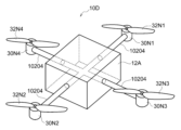
- FIG. 11 is a partial perspective view of the upper part of aircraft 10D of the fourth embodiment
- FIG. 11 is an overall perspective view of an aircraft 10E according to a fifth embodiment
- FIG. 11 is an overall perspective view of an aircraft 10F according to a sixth embodiment
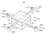
- FIG. 21 is a partial perspective view of the upper part of the aircraft 10G of the seventh embodiment
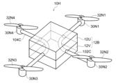
- FIG. 21 is a partial perspective view of the upper part of aircraft 10H of the eighth embodiment
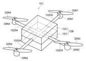
- FIG. 21 is a partial perspective view of the upper part of aircraft 10I of the ninth embodiment
- FIG. 1 shows an overall perspective view of an aircraft 10A.
- the aircraft 10A has a main body 12A that is integrally constructed.
- the main body 12A is a substantially rectangular parallelepiped having a top surface, a bottom surface and four side surfaces.
- the main body 12A may be substantially spherical, substantially dome-shaped, or the like.
- the aircraft 10A comprises a support having multiple ends and passing through the body 12A.
- the support includes a first arm 14, a second arm 16, a first retainer 18, a second retainer 20, a first support arm 22, and a second support arm 24, which will be described in detail below. I have.
- the first arm 14 and the second arm 16 pass through the main body 12A.
- the aircraft 10A includes a first arm 14 and a second arm 14 each having opposite ends and penetrating the body 12A via two opposite sides (left and right sides in FIG. 1) of the four sides of the body 12A. and an arm 16 of The first arm 14 and the second arm 16 have substantially the same length and are arranged substantially parallel to each other.
- aircraft 10A has two arms, the first arm 14 and the second arm 16, but the technology of the present disclosure is not limited to this.
- aircraft 10A may have one arm with opposite ends, or may have more than two arms, each with opposite ends.
- the first arm 14 and the second arm 16 are examples of the "first arm section" of the technology of the present disclosure.
- the aircraft 10A includes, for example, an inserted first holding portion 18 located at one end of each of the first arm 14 and the second arm 16 (right end in FIG. 1), and a second A second retainer 20, for example inserted, is located at the other end of each of the first arm 14 and the second arm 16 (the left end in FIG. 1).
- Each of the first holding portion 18 and the second holding portion 20 is a substantially rectangular parallelepiped having a top surface, a bottom surface and four side surfaces.
- the end of the first arm 14 is inserted into one of the four side surfaces of the first holding portion 18 facing the main body 12A (the left side surface in FIG. 1), and the four side surfaces of the second holding portion 20
- the end of the first arm 14 is inserted into the side surface facing the main body 12A (the side surface on the right side in FIG. 1).
- the end portion is a portion that includes the end and is located within a predetermined range from the end.
- the end of the first arm 14 is the portion of the range that includes the tip of the arm 14 and is a processing distance from the tip to the center.
- the aircraft 10A has a first support penetrating through the first holding part 18 via two opposing sides (sides on the far side and front side in FIG. 1) of the four sides of the first holding part 18.
- An arm 22 is provided.
- the aircraft 10A has a second support penetrating through the second holding part 20 via two opposing sides (sides on the far side and front side in FIG. 1) of the four sides of the second holding part 20.
- An arm 24 is provided.
- the first support arm 22 and the second support arm 24 have substantially the same length and are arranged substantially parallel to each other.
- first support arm 22 may be divided into two and each divided arm may be inserted into the first holding portion 18 .
- second holding part 20 may be split into two and each split arm may be inserted into the second support arm 24 .
- Each of the first support arm 22 and the second support arm 24 is an example of the "second arm section" of the technology of the present disclosure.
- Each of the first arm 14, the second arm 16, the first support arm 22, and the second support arm 24 is a cylinder (that is, a hollow pipe), and their central axes are located substantially on the same plane. do.
- Each of the first arm 14, the second arm 16, the first support arm 22, and the second support arm 24 may be a prism, a flat plate, or the like.
- the aircraft 10A includes a first motor 30N1 into which one end of the first support arm 22 is inserted, a second motor 30N2 into which the other end of the first support arm 22 is inserted, and a second support arm.
- the aircraft 10A includes a first propeller 32N1 rotated by a first motor 30N1, a second propeller 32N2 rotated by a second motor 30N2, a third propeller 32N3 rotated by a third motor 30N3, and a third propeller 32N3. and a fourth propeller 32N4 rotated by four motors 30N4.
- the aircraft 10A includes a first support column 42 with one end inserted into the bottom surface of the main body 12A, and a second support column 44 with one end inserted into the bottom surface of the main body 12A.
- the other end of the first support column 42 is inserted into the first connecting portion 46 .
- the other end of the second support column 44 is inserted into the second connecting portion 48 .
- the first support column 42 and the second support column 44 are not parallel to each other, but are arranged away from each other from one end to the other end.
- a first holding column 52 penetrates through the first connecting portion 46
- a second holding column 54 penetrates through the second connecting portion 48 .
- the first holding column 52 and the second holding column 54 are arranged substantially parallel to each other.
- a third holding column 56 is inserted between the first connecting portion 46 and the second connecting portion 48 so that the distance between the first connecting portion 46 and the second connecting portion 48 is maintained. ing.
- the third retention post 56 intersects (eg, is orthogonal to) the first retention post 52 and the second retention post 54 .
- Each of the first retaining column 52, the second retaining column 54, and the third retaining column 56 is a cylinder (that is, a hollow pipe), and their central axes are located substantially on the same plane.
- Each of the first retaining post 52, the second retaining post 54, and the third retaining post 56 may be a prism, a flat plate, or the like.
- Each of the first support column 42 and the second support column 44 is a cylinder (that is, a hollow pipe), and their central axes are located substantially on the same plane.
- Each of the first support column 42 and the second support column 44 may be a prism, a flat plate, or the like.
- a third plane in which the central axis of each of the first support column 42 and the second support column 44 is located intersects (eg, orthogonally crosses) each of the first plane and the second plane.
- a three-dimensional printer (hereinafter referred to as a "3D printer") is used to form the main body 12A, the first holding portion 18, the second holding portion 20, and the first holding portion 18 using a resin containing a carbon component.
- Each of the connecting portion 46 and the second connecting portion 48 is integrally manufactured.
- each of the main body 12A, the first holding portion 18, the second holding portion 20, the first connecting portion 46, and the second connecting portion 48 is divided into a first member and a second member. Instead, it can be constructed from one member (ie, block).
- the order of manufacturing the main body 12A, the first holding portion 18, the second holding portion 20, the first connecting portion 46, and the second connecting portion 48 is not limited to this.
- the second holding portion 20 may be arranged in the reverse order, or in the order of the first holding portion 18, the second holding portion 20, the first connecting portion 46, the second connecting portion 48, and the main body 12A. , the first connecting portion 46, the second connecting portion 48, the main body 12A, and the first holding portion 18, or the like. Furthermore, the main body 12A, the first retaining portion 18, the second retaining portion 20, the first connecting portion 46, and the second connecting portion 48 may be manufactured at the same time.
- the first holding portion 18 has a groove into which one end of the first arm 14 and the second arm 16 can be inserted, and a through hole through which the first support arm 22 can pass.
- the second holding portion 20 is formed with a groove into which the other ends of the first arm 14 and the second arm 16 can be inserted, and a through hole through which the second support arm 24 can pass.
- the first connecting portion 46 is formed with grooves into which the respective ends of the first support column 42 and the third holding column 56 can be inserted, and through holes through which the first holding column 52 can pass.
- the second connecting portion 48 is formed with grooves into which the respective ends of the second support column 44 and the third holding column 56 can be inserted, and through holes through which the second holding column 54 can pass. do.
- grooves into which the flight controller and electrical wiring can be inserted are formed in the main body 12A.
- step (b) a support having a plurality of ends and penetrating the main body 12A is manufactured.
- the support is manufactured as follows.
- step (b-1) the first arm 14 and the second arm 16 prepared in advance are passed through the main body 12A.
- step (b-2) one end of each of the first arm 14 and the second arm 16 (the right end in FIG. 1) is attached to one of the four side surfaces of the first holding portion 18.
- the side facing the main body 12A left side in FIG. 1 is inserted.
- step (b-3) each of the other ends of the first arm 14 and the second arm 16 (the left end in FIG. 1) is attached to the inner four side surfaces of the second holding part 20.
- the side facing the main body 12A (right side in FIG. 1) is inserted.
- step (b-4) two of the four side surfaces of the first holding portion 18 are provided in advance on the first holding portion 18 via two opposite side surfaces (side surfaces on the back side and the front side in FIG. 1).
- the first support arm 22 that has been extended is penetrated.
- step (b-5) two of the four side surfaces of the second holding portion 20 are provided in advance on the second holding portion 20 through two opposite side surfaces (side surfaces on the back side and the front side in FIG. 1). 2nd support arm 24 which carried out is penetrated
- steps (b-1) to (b-5) is not limited to this.
- step (b-2), step (b-4), step (b-1), step (b-3), and step (b-5) may be in order
- step (b-4), step (b-5), step (b-2), step (b-1), and step (b-3) may be performed in that order.
- step (c) the motor and propeller are arranged.
- step (c-1) the first motor 30N1 and the first propeller 32N1 are arranged at one end of the first support arm 22.
- step (c-2) the second motor 30N2 and the second propeller 32N2 are arranged at the other end of the first support arm 22. As shown in FIG.
- a third motor 30N3 and a third propeller 32N3 are arranged at one end of the second support arm 24.
- the fourth motor 30N4 and the fourth propeller 32N4 are arranged at the other end of the second support arm 24. As shown in FIG.
- steps (d-1) to (d-4) is not limited to this.
- step (d-2), step (d-3), step (d-4), step (d-1), step (d-3), step (d-4), step The order of (d-1), step (d-2), etc. may also be used.
- the support portion of the main body 12A is manufactured.
- step (d-1) one end of each of the first support column 42 and the second support column 44 is inserted into the bottom surface of the main body 12A.
- step (d-2) the first connecting portion 46 and the second connecting portion 48 are inserted into the other ends of the first support column 42 and the second support column 44, respectively.
- step (d-3) the first connecting portion 46 is passed through the first holding column 52, and the second connecting portion 48 is passed through the second holding column 54.
- step (d-4) a third holding column 56 is attached to the first connecting portion 46 and the second connecting portion 48 so that the distance between the first connecting portion 46 and the second connecting portion 48 is maintained. Insert as shown.
- steps (d-1) to (d-4) is not limited to this.
- step (d-2), step (d-3), step (d-4), step (d-1), step (d-2), step (d-3), step (d-4) and step (d-1) may be performed in that order.
- step (e) the flight controller, electrical wiring, etc. are inserted into the main body 12A. Arrange electrical wiring between the flight controller and the first motor 30N1 to the fourth motor 30N4. The electrical wiring from the main body 12A is connected to the first arm 14, the second arm 16, the first holding portion 18, the second holding portion 20, the first support arm 22, and the second support arm 24. Place on (or in) the surface.
- the main body 12A and the support are manufactured separately using a 3D printer, but the technology of the present disclosure is not limited to this.
- the main body 12A and the support as a whole may be integrally manufactured by a 3D printer.
- the material of the first arm 14 and the second arm 16 is different from the material of the main body 12A by using a 3D printer so that the first arm 14 and the second arm 16 pass through the main body 12A. In this way, it may be manufactured integrally.
- the material of the first support arm 22 and the material of the first holding part 18 are made different by a 3D printer so that the first supporting arm 22 penetrates the first holding part 18, and the material of the first holding part 18 is made to be integrally manufactured. You may Using a 3D printer, the material of the second holding part 20 and the material of the second supporting arm 24 are made different so that the second holding part 20 penetrates the second supporting arm 24, and integrally manufactured You may As a result, the main body 12A and the support are integrally configured as a whole.
- each of the main body 12A, the first retaining portion 18, the second retaining portion 20, the first connecting portion 46, and the second connecting portion 48 is a first member and a second member. It is composed of one member (that is, a block) without being divided into halves.
- the present embodiment can make the aircraft 10A more difficult to disassemble than the conventional aircraft.
- each Strength can be greater than conventional aircraft.
- the main body 12A, the first holding portion 18, the second holding portion 20, the first connecting portion 46, and the second connecting portion 48 are formed using a resin containing a carbon component by a 3D printer. Since each of them is integrally manufactured, the strength of each can be made greater than that of conventional aircraft. Therefore, the present embodiment can make the aircraft 10A more difficult to disassemble than the conventional aircraft.
- the number of parts can be reduced by eliminating the members that connect the upper and lower plates. Therefore, according to the present embodiment, the aircraft 10A can be made more difficult to disassemble than the conventional aircraft.
- the first arm 14 and the second arm 16 do not have one ends inserted into the main body 12A, but pass through the main body 12A. It is possible to prevent the arm 16 from coming off the main body 12A.
- the present embodiment can make the aircraft 10A more difficult to disassemble than the conventional aircraft.
- each of the main body 12A, the first holding portion 18, the second holding portion 20, the first connecting portion 46, and the second connecting portion 48 is manufactured by injection molding.
- injection molding a mold with a cavity that has the same shape as the product is made, the heated carbon is poured into the mold, cooled, and the unnecessary part of the cooled carbon is cut. , the main body 12A, the first retaining portion 18, the second retaining portion 20, the first connecting portion 46, and the second connecting portion 48, respectively.
- This requires large-scale equipment and requires a relatively long time. If you ask a manufacturing company that already has large-scale equipment to manufacture the product without preparing large-scale equipment, it will take a longer time for ordering, transportation, and the like.
- each of the main body 12A, the first holding portion 18, the second holding portion 20, the first connecting portion 46, and the second connecting portion 48 is manufactured by a 3D printer, it can be easily manufactured.
- Each of the main body 12A, the first holding portion 18, the second holding portion 20, the first connecting portion 46, and the second connecting portion 48, as well as the drone, can be manufactured with simple equipment and in a short time. .
- each of the first arm 14, the second arm 16, the first support arm 22, the second support arm 24, the first retention column 52, the second retention column 54, and the third retention column 56 consists of hollow pipes.
- each of the first arm 14, the second arm 16, the first support arm 22, the second support arm 24, the first retention post 52, the second retention post 54, and the third retention post 56 and eventually the weight of the drone can be reduced.
- first arm 14 and the second arm 14 penetrate the main body 12A via two opposing side surfaces (left and right side surfaces in FIG. 1) of the four side surfaces of the main body 12A and are arranged substantially parallel to each other. 2 arms 16; Note that the description of other structural parts of the support is omitted.
- the technology of the present disclosure is not limited to this.
- multiple supports may be provided.
- the first main body 12A penetrates through the main body 12A via two opposing side surfaces (the side surfaces on the back side and the front side in FIG. 1) of the four side surfaces of the main body 12A and is arranged substantially parallel to each other.
- An arm and a second arm may be provided.
- the main body 12A may be composed of more than 4 polygonal prisms (6, 8, 10, etc. polygonal prisms), each opposing side face being penetrated by a support.
- FIG. 2 shows a partial perspective view of the upper portion of the aircraft 10B of the second embodiment. Since the aircraft 10B of the second embodiment has the same configuration as the aircraft 10A of the first embodiment in the main body 12A and the portion below the main body 12A, description thereof will be omitted. As shown in FIG. 2, the aircraft 10B of the second embodiment includes the first arm 14 and the second arm 16, the first holding portion 18 and the second arm of the aircraft 10A of the first embodiment. A first arm 102 and a second arm 104 passing through the main body 12A are provided instead of the holding portion 20 and the first support arm 22 and the second support arm 24 . The first arm 102 and the second arm 104 have substantially the same length and are arranged inside the main body 12A such that they are spaced apart and their longitudinal directions are substantially perpendicular to each other.
- Each of the first arm 102 and the second arm 104 has one end and the other end.
- One end of the first arm 102 is provided with a first motor 30N1 and a first propeller 32N1 rotated by the first motor 30N1.
- the other end of the first arm 102 is provided with a second motor 30N2 and a second propeller 32N2 rotated by the second motor 30N2.
- One end of the second arm 104 is provided with a third motor 30N3 and a first propeller 32N3 rotated by the third motor 30N3.
- the other end of the second arm 104 is provided with a fourth motor 30N4 and a fourth propeller 32N4 rotated by the fourth motor 30N4.
- the first arm 102 and the second arm 104 are examples of the "support” and the “plurality of arms” of the technology of the present disclosure.
- main body 12A of the aircraft 10A of the first embodiment is a rectangular parallelepiped, while the main body 12A of the aircraft 10B of the second embodiment is a cube.
- the main body 12A may be composed of polygonal prisms larger than 4 (polygonal prisms such as 6, 8, 10, etc.), and arms having motors and propellers at both ends may be passed through each opposing side surface.
- a through hole is formed through which the first arm 102 and the second arm 104 can pass.
- the support body (first arm 102 and second arm 104) is passed through the main body 12A.
- a first motor 30N1 and a first propeller 32N1 are provided at one end of the first arm 102, and a second motor 30N2 and a second propeller 32N2 are provided at the other end of the first arm 102.
- a third motor 30N3 and a first propeller 32N3 are provided at one end of the second arm 104, and a fourth motor 30N4 and a fourth propeller 32N4 are provided at the other end of the second arm 104.
- the order in which the motors and propellers are provided is not limited to this.
- FIG. 3 shows a partial perspective view of the upper part of the aircraft 10C of the third embodiment. Since the aircraft 10C of the third embodiment has substantially the same configuration as the aircraft 10B of the second embodiment, only different parts will be described.
- the aircraft 10C has a first arm 102 and a second arm 104.
- the first arm 102 and the second arm 104 have approximately the same length.
- first arm 102 and the second arm 104 of the second embodiment aircraft 10B are cylindrical (see FIG. 2), they penetrate the body 12A of the third embodiment aircraft 10C.
- the first arm 102C and the second arm 104C are different in that they are bent inside the main body 12A.
- the first arm 102 and the second arm 104 of the aircraft 10B of the second embodiment pass through opposite sides of the body 12A, whereas the arms of the aircraft 10C of the third embodiment pass through opposite sides.
- the first arm 102C and the second arm 104C are different in that they pass through adjacent side surfaces of the main body 12A.
- the main body 12A is composed of polygonal prisms larger than 4 (polygonal prisms such as 6, 8, 10, etc.), and arms having motors and propellers at both ends are bent through the main body 12A on each adjacent side surface.
- the main body 12A, the first arm 102C and the second arm 104C are integrally manufactured by a 3D printer using different materials.
- FIG. 4 shows a partial perspective view of the upper part of the aircraft 10D of the fourth embodiment. Since the aircraft 10D of the fourth embodiment has substantially the same configuration as the aircraft 10B of the second embodiment, only different parts will be described.
- the aircraft 10D is equipped with an arm 10204.
- the aircraft 10B of the second embodiment comprises a first arm 102 and a second arm 104 which are separated from each other and whose longitudinal directions are substantially perpendicular to each other (see FIG. 2),
- the aircraft 10D of the fourth embodiment is different in that the first arm 102 and the second arm 104 intersect, for example, a single arm 10204 that is orthogonal and integrally constructed.
- the main body 12A is constructed of polygonal prisms greater than 4 (polygonal prisms such as 5, 6, 7, 8, 9, 10, etc.) and is manufactured from each side to pass through an arm having a motor and a propeller at one end.
- the main body 12A and the arm 10204 are integrally manufactured by a 3D printer using different materials.
- FIG. 5 shows an overall perspective view of an aircraft 10E according to the fifth embodiment. Since the aircraft 10E of the fifth embodiment has substantially the same configuration as the aircraft 10A of the first embodiment, only different parts will be described.
- the aircraft 10E includes a main body 12A integrally configured and a plurality of (for example, two) support portions having one end inserted into the main body 12A.
- the multiple supports may be, for example, two supports (a first support and a second support).
- the first support section includes a first arm 14B, a second arm 16B, a first holding section 18, and a first support arm 22, which will be described later in detail.
- the second support includes a first arm 14A, a second arm 16A, a second retainer 20, and a second support arm 24. As shown in FIG. In particular, one end of each of the first arm 14A, the second arm 16A, the first arm 14B, and the second arm 16B is inserted into the main body 12A.
- first arm 14 and the second arm 16 pass through the body 12A, whereas in the aircraft 10E of the fifth embodiment, the first arm 14 and the second arm 16 extend through the body 12A.
- Each of the two arms 16 is divided into two, and one end of each of the first arms 14A, 14B and the second arms 16A, 16B divided into two is inserted into the main body 12. differ in
- the aircraft 10E includes four arms, first arms 14A, 14B and second arms 16A, 16B, but the technology of the present disclosure is not limited to this.
- each of the first and second supports of aircraft 10E may comprise one arm having opposite ends, or may comprise more than two arms each having opposite ends. You may
- the first arms 14A, 14B and the second arms 16A, 16B are examples of the "arm section" of the technology of the present disclosure.
- a motor and a propeller rotated by the motor are arranged at the other ends of the first support and the second support, and at each of the plurality of ends of the support. Specifically, one end of each of the first arms 14A, 14B and the second arms 16A, 16B is inserted into the body 12A.
- FIG. 6 shows an overall perspective view of an aircraft 10F according to the sixth embodiment. Since the aircraft 10F of the sixth embodiment has substantially the same configuration as the aircraft 10A of the first embodiment, only different parts will be described.
- the main body 12A of the aircraft 10A of the first embodiment is not divided into an upper member and a lower member, but is composed of one member, whereas the main body 12B of the aircraft 10F of the sixth embodiment is different in that it includes an upper member 12U and a lower member 12D.
- the upper member 12U and the lower member 12D are examples of the “first member” and the “second member” of the technology of the present disclosure.
- the main body 12B is manufactured by manufacturing the upper member 12U and the lower member 12D using a 3D printer.
- the upper member 12U and the lower member 12D are connected with the support, in particular, the first arm 14 and the second arm 16 passing therethrough.
- the upper member 12U and the lower member 12D are connected by a connecting portion such as a screw, for example.
- FIGS. 7-9 show partial perspective views of the upper portion of the aircraft 10G-10I of the seventh-ninth embodiments.
- Aircraft 10G to 10I of the seventh to ninth embodiments have substantially the same configuration as aircraft 10B to 10D of the second to fourth embodiments, so only different parts will be described.
- the main body 12A of the aircraft 10B-D of the second to fourth embodiments is not divided into upper and lower members, but is composed of one member, whereas in the seventh to ninth embodiments.
- the main body 12B of the aircraft 10G-10I differs in that it comprises an upper member 12U and a lower member 12D.
- the method of manufacturing the aircraft 10G-10I of the seventh to ninth embodiments has substantially the same configuration as the manufacturing of the aircraft 10B-D of the second to fourth embodiments, so only different parts will be described.
- the main body 12B is manufactured by manufacturing the upper member 12U and the lower member 12D using a 3D printer.
- the first arm 102 is passed through the upper member 12U, and the second arm 104 is passed through the lower member 12D.
- a first arm 102 penetrates the upper member 12U and a second arm 104 penetrates the lower member 12D, thereby connecting the upper member 12U and the lower member 12D.
- the upper member 12U and the lower member 12D are connected so that the first arm 102C and the second arm 104C pass through.
- the upper member 12U and the lower member 12D are connected so that the arm 10204 penetrates.
- the main body 12B is composed of polygonal prisms larger than 4 (polygonal prisms such as 6, 8, 10, etc.), and each opposing side surface is provided with a motor at each end. and an arm with a propeller may be passed through.
- the main body 12B is composed of polygonal prisms larger than 4 (polygonal prisms such as 6, 8, 10, etc.), and each adjacent side surface is provided with motors at both ends. and propeller arms may be bent through body 12A.
- the main body 12B is composed of polygonal prisms larger than 4 (polygonal prisms such as 5, 6, 7, 8, 9, 10, etc.), and from each side, It may be manufactured to pass through an arm with a motor and propeller at one end.
- Each of the above aircraft is, for example, a drone (that is, a rotary wing aircraft), but may also be a vertical takeoff and landing (VTOL (Vertical Takeoff and Landing)) aircraft having a propeller, a fixed wing aircraft having a propeller, or a helicopter.
- VTOL Vertical Takeoff and Landing
- the aircraft may be manned or unmanned.
- the first to ninth embodiments described above are merely examples. Therefore, it is possible to delete unnecessary configurations, add new configurations, delete unnecessary processing steps, add new processing steps, and change the processing order within the scope of the gist. It goes without saying that this is also a good thing.
Landscapes
- Engineering & Computer Science (AREA)
- Aviation & Aerospace Engineering (AREA)
Priority Applications (2)
| Application Number | Priority Date | Filing Date | Title |
|---|---|---|---|
| PCT/JP2022/003300 WO2023144994A1 (ja) | 2022-01-28 | 2022-01-28 | 航空機及び航空機の製造方法 |
| JP2023576512A JPWO2023144994A1 (https=) | 2022-01-28 | 2022-01-28 |
Applications Claiming Priority (1)
| Application Number | Priority Date | Filing Date | Title |
|---|---|---|---|
| PCT/JP2022/003300 WO2023144994A1 (ja) | 2022-01-28 | 2022-01-28 | 航空機及び航空機の製造方法 |
Publications (1)
| Publication Number | Publication Date |
|---|---|
| WO2023144994A1 true WO2023144994A1 (ja) | 2023-08-03 |
Family
ID=87470919
Family Applications (1)
| Application Number | Title | Priority Date | Filing Date |
|---|---|---|---|
| PCT/JP2022/003300 Ceased WO2023144994A1 (ja) | 2022-01-28 | 2022-01-28 | 航空機及び航空機の製造方法 |
Country Status (2)
| Country | Link |
|---|---|
| JP (1) | JPWO2023144994A1 (https=) |
| WO (1) | WO2023144994A1 (https=) |
Cited By (1)
| Publication number | Priority date | Publication date | Assignee | Title |
|---|---|---|---|---|
| WO2026069447A1 (ja) * | 2024-09-25 | 2026-04-02 | 株式会社ワールドスキャンプロジェクト | 回転翼機及び回転翼機用フレームユニット |
Citations (8)
| Publication number | Priority date | Publication date | Assignee | Title |
|---|---|---|---|---|
| JP2016064768A (ja) * | 2014-09-25 | 2016-04-28 | 勉 横山 | マルチコプター |
| WO2017120654A1 (en) * | 2016-01-12 | 2017-07-20 | Dragan, Zenon | Multi-rotor uav with compact folding rotor arms |
| JP2018039507A (ja) * | 2017-11-09 | 2018-03-15 | エスゼット ディージェイアイ テクノロジー カンパニー リミテッドSz Dji Technology Co.,Ltd | 無人航空機、及び無人航空機で慣性計測ユニットを分離する方法 |
| WO2019062139A1 (zh) * | 2017-09-30 | 2019-04-04 | 深圳市道通智能航空技术有限公司 | 一种无人飞行器 |
| JP2019069658A (ja) * | 2017-10-06 | 2019-05-09 | ヤマハ発動機株式会社 | 無人飛行体用フレーム |
| JP2020000111A (ja) * | 2018-06-28 | 2020-01-09 | 株式会社マゼックス | 無人飛行体 |
| JP2020153844A (ja) * | 2019-03-20 | 2020-09-24 | 新日本非破壊検査株式会社 | マルチコプターを用いた計測器移動補助装置 |
| JP2021088256A (ja) * | 2019-12-04 | 2021-06-10 | 株式会社プロドローン | 無人航空機 |
Family Cites Families (1)
| Publication number | Priority date | Publication date | Assignee | Title |
|---|---|---|---|---|
| JP6952389B1 (ja) * | 2020-09-29 | 2021-10-20 | 株式会社エアロネクスト | 飛行体 |
-
2022
- 2022-01-28 JP JP2023576512A patent/JPWO2023144994A1/ja active Pending
- 2022-01-28 WO PCT/JP2022/003300 patent/WO2023144994A1/ja not_active Ceased
Patent Citations (8)
| Publication number | Priority date | Publication date | Assignee | Title |
|---|---|---|---|---|
| JP2016064768A (ja) * | 2014-09-25 | 2016-04-28 | 勉 横山 | マルチコプター |
| WO2017120654A1 (en) * | 2016-01-12 | 2017-07-20 | Dragan, Zenon | Multi-rotor uav with compact folding rotor arms |
| WO2019062139A1 (zh) * | 2017-09-30 | 2019-04-04 | 深圳市道通智能航空技术有限公司 | 一种无人飞行器 |
| JP2019069658A (ja) * | 2017-10-06 | 2019-05-09 | ヤマハ発動機株式会社 | 無人飛行体用フレーム |
| JP2018039507A (ja) * | 2017-11-09 | 2018-03-15 | エスゼット ディージェイアイ テクノロジー カンパニー リミテッドSz Dji Technology Co.,Ltd | 無人航空機、及び無人航空機で慣性計測ユニットを分離する方法 |
| JP2020000111A (ja) * | 2018-06-28 | 2020-01-09 | 株式会社マゼックス | 無人飛行体 |
| JP2020153844A (ja) * | 2019-03-20 | 2020-09-24 | 新日本非破壊検査株式会社 | マルチコプターを用いた計測器移動補助装置 |
| JP2021088256A (ja) * | 2019-12-04 | 2021-06-10 | 株式会社プロドローン | 無人航空機 |
Cited By (1)
| Publication number | Priority date | Publication date | Assignee | Title |
|---|---|---|---|---|
| WO2026069447A1 (ja) * | 2024-09-25 | 2026-04-02 | 株式会社ワールドスキャンプロジェクト | 回転翼機及び回転翼機用フレームユニット |
Also Published As
| Publication number | Publication date |
|---|---|
| JPWO2023144994A1 (https=) | 2023-08-03 |
Similar Documents
| Publication | Publication Date | Title |
|---|---|---|
| WO2023144994A1 (ja) | 航空機及び航空機の製造方法 | |
| CN205499318U (zh) | 多旋翼无人机机架中心件 | |
| US20250058243A1 (en) | Magnetic suction building block | |
| US20200171400A1 (en) | Building block | |
| JPH02221545A (ja) | トラスビーム取付装置 | |
| KR20210093238A (ko) | 3차원 구조 생성을 위한 구축 시스템 | |
| CN104890865B (zh) | 机臂组件、机架及无人机 | |
| CN110997092A (zh) | 方块型组件块系统 | |
| CA1178055A (en) | Constructional building set | |
| EP3878533B1 (en) | Model construction set | |
| US7954296B2 (en) | Radial tetrahedral modular structures | |
| CN213897568U (zh) | 墙面以及重型木屋 | |
| KR20230086196A (ko) | 골판지 조각을 이용한 탈장착 구조를 갖는 조립식 드론 | |
| CN107031813A (zh) | 多旋翼无人机机架中心件 | |
| CN206288232U (zh) | 一种多旋翼无人机的机架 | |
| CN105521611A (zh) | 一种多向连接球 | |
| CN118727929A (zh) | 一种钢结构标准化结构体系 | |
| CN105597339A (zh) | 多孔多面体积木 | |
| US20200216988A1 (en) | Additive manufacturing-3d printing of three-dimensional woven structures | |
| CN210356034U (zh) | 板材拼装立体场景及其基座 | |
| CN215043668U (zh) | 一种可拆卸无人机支架 | |
| KR102604206B1 (ko) | 복수의 단위 블록 및 링크를 갖는 조립 구조체 | |
| JP3197214U (ja) | 組立ブロックおもちゃ | |
| CN100556579C (zh) | 组合式浇注模具及其制造方法 | |
| CN110975306B (zh) | 积木玩具 |
Legal Events
| Date | Code | Title | Description |
|---|---|---|---|
| 121 | Ep: the epo has been informed by wipo that ep was designated in this application |
Ref document number: 22923858 Country of ref document: EP Kind code of ref document: A1 |
|
| DPE1 | Request for preliminary examination filed after expiration of 19th month from priority date (pct application filed from 20040101) | ||
| NENP | Non-entry into the national phase |
Ref country code: DE |
|
| WWE | Wipo information: entry into national phase |
Ref document number: 2023576512 Country of ref document: JP |
|
| 122 | Ep: pct application non-entry in european phase |
Ref document number: 22923858 Country of ref document: EP Kind code of ref document: A1 |