WO2023144875A1 - 接続装置 - Google Patents
接続装置 Download PDFInfo
- Publication number
- WO2023144875A1 WO2023144875A1 PCT/JP2022/002603 JP2022002603W WO2023144875A1 WO 2023144875 A1 WO2023144875 A1 WO 2023144875A1 JP 2022002603 W JP2022002603 W JP 2022002603W WO 2023144875 A1 WO2023144875 A1 WO 2023144875A1
- Authority
- WO
- WIPO (PCT)
- Prior art keywords
- gas
- bushing
- oil
- tank
- insulating spacer
- Prior art date
- Legal status (The legal status is an assumption and is not a legal conclusion. Google has not performed a legal analysis and makes no representation as to the accuracy of the status listed.)
- Ceased
Links
Images

Classifications
-
- H—ELECTRICITY
- H02—GENERATION; CONVERSION OR DISTRIBUTION OF ELECTRIC POWER
- H02B—BOARDS, SUBSTATIONS OR SWITCHING ARRANGEMENTS FOR THE SUPPLY OR DISTRIBUTION OF ELECTRIC POWER
- H02B13/00—Arrangement of switchgear in which switches are enclosed in, or structurally associated with, a casing, e.g. cubicle
- H02B13/02—Arrangement of switchgear in which switches are enclosed in, or structurally associated with, a casing, e.g. cubicle with metal casing
- H02B13/035—Gas-insulated switchgear
- H02B13/045—Details of casing, e.g. gas tightness
Definitions
- the present disclosure relates to a connection device that connects oil-insulated equipment and gas-insulated equipment.
- a connection device called a bushing as disclosed in Patent Document 1 is used.
- the bushing has a closed structure in which a central conductor is housed in a cylindrical bushing tank, and the bushing tank is filled with insulating gas.
- a method of detecting an abnormality such as a gas leak by monitoring the gas pressure of the insulating gas inside the bushing tank is widely used.
- a bushing with a closed structure requires sensors to monitor the gas pressure of the insulating gas in the bushing tank.
- sensors in order to withstand the increase in internal pressure when flashover occurs in the bushing tank, it is necessary to increase the volume of the bushing tank and install a pressure relief device, which reduces the number of parts and It was difficult to achieve compatibility with miniaturization.
- the present disclosure has been made in view of the above, and an object thereof is to obtain a connection device capable of connecting an oil-insulated device and a gas-insulated device and achieving a reduction in the number of parts and miniaturization.
- a connection device is installed between an oil-insulated device and a gas-insulated device to provide an inner conductor of the oil-insulated device and an inner conductor of the gas-insulated device a tubular bushing tank, a tubular gas side insulating spacer installed at one end of the bushing tank, and a tubular oil installed at the other end of the bushing tank.
- the contact portion includes a center conductor protruding from the oil-side insulating spacer in the axial direction of the bushing tank.
- a gas-side contact portion or a gas-side insulating spacer is formed with a vent hole that connects the inside and outside of the bushing tank.
- connection device it is possible to connect oil-insulated equipment and gas-insulated equipment, and it is possible to reduce the number of parts and reduce the size.
- FIG. 2 shows a state in which the bushing according to Embodiment 1 is installed between an oil-insulated device and a gas-insulated device; The figure which shows the state which installed the bushing which concerns on Embodiment 2 between the oil insulated equipment and the gas insulated equipment.
- connection device according to the embodiment will be described in detail based on the drawings.
- FIG. 1 is a cross-sectional view showing the configuration of a bushing according to Embodiment 1.
- the bushing 100 which is the connection device according to the first embodiment, includes a tubular bushing tank 10, a spacer ring 20 installed at one end of the bushing tank 10, and a tubular gas side insulating spacer fixed to the spacer ring 20. 30, a cylindrical oil-side insulating spacer 40 installed at the other end of the bushing tank 10, and a center conductor 50 passing through the gas-side insulating spacer 30, the spacer ring 20, the bushing tank 10, and the oil-side insulating spacer 40.
- a tubular bushing tank 10 which is the connection device according to the first embodiment, includes a tubular bushing tank 10, a spacer ring 20 installed at one end of the bushing tank 10, and a tubular gas side insulating spacer fixed to the spacer ring 20. 30, a cylindrical oil-side insulating spacer 40 installed at the other end of the bushing tank 10, and a center conductor
- the oil-side insulating spacer 40 and the gas-side insulating spacer 30 can be formed using resin as a material. Also, the bushing tank 10 and the central conductor 50 can be formed using aluminum as a material. Note that the oil-side insulating spacer 40, the gas-side insulating spacer 30, the bushing tank 10, and the central conductor 50 may be formed using materials different from those illustrated.
- a flange 11 is formed at one end of the bushing tank 10 and the spacer ring 20 is fixed to the flange 11 .
- Through holes 111 and 21 are formed in the flange 11 and the spacer ring 20, respectively. Through hole 111 and through hole 21 are connected in the axial direction of bushing tank 10 .
- a flange 12 is formed at the other end of the bushing tank 10 , and the oil side insulating spacer 40 is fixed to the flange 12 .
- the bushing tank 10 also has an intermediate flange 13 formed between one end and the other end.
- One end of the central conductor 50 protruding from the gas-side insulating spacer 30 in the axial direction of the bushing tank 10 serves as a gas-side contact portion 51 connected to the internal conductor of the gas-insulated equipment.
- the other end portion of the center conductor 50 protruding from the oil side insulating spacer 40 in the axial direction of the bushing tank 10 serves as an oil side contact portion 52 connected to the internal conductor of the oil-insulated device.
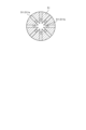
- FIG. 2 is a cross-sectional view of the gas side contact portion of the bushing according to Embodiment 1.
- FIG. FIG. 2 shows a cross section along line II-II in FIG.
- a plurality of vent holes 511 are formed in the gas side contact portion 51 .
- the plurality of vent holes 511 includes a first vent hole 511a radially extending from the center of the gas side contact portion 51 and a second vent hole 511b extending in the axial direction of the bushing tank 10.
- the first vent hole 511a and the second air hole 511b are connected.
- a plurality of vent holes 511 pass through the gas side contact portion 51 , and the inside and outside of the bushing tank 10 are connected through the vent holes 511 .
- vent holes 511 are formed in the gas side contact portion 51 .
- at least one vent hole 511 may be formed in the gas side contact portion 51 .
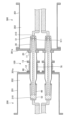
- FIG. 3 is a diagram showing a state in which the bushing according to Embodiment 1 is installed between the oil-insulated equipment and the gas-insulated equipment.
- Bushing 100 is installed between oil-insulated equipment 200 and gas-insulated equipment 300 and electrically connects internal conductor 210 of oil-insulated equipment 200 and internal conductor 310 of gas-insulated equipment 300 .
- Insulating oil 202 is enclosed in the oil-insulated equipment tank 201 of the oil-insulated equipment 200 .
- An insulating gas 302 such as SF6 is sealed in a gas-insulated equipment tank 301 of the gas-insulated equipment 300 .
- the gas insulation equipment 300 includes a sensor for detecting the gas pressure of the insulating gas 302 in the gas insulation equipment tank 301 .
- the bushing 100 has the gas side insulating spacer 30 and the gas side contact portion 51 inserted into the gas insulating equipment tank 301 .
- the spacer ring 20 is abutted against the end face plate 301a of the gas insulation equipment tank 301.
- the bushing 100 is fixed to the gas-insulated equipment 300 by screwing a bolt (not shown) passing through the through hole 111 of the flange 11 and the through hole 21 of the spacer ring 20 to the end plate 301a.
- the bushing 100 has the oil-side contact portion 52 , the oil-side insulating spacer 40 , and a portion of the bushing tank 10 on the other end portion side inserted into the oil-insulated equipment tank 201 .
- a bellows 70 is fixed to the end face plate 201a of the oil-insulated equipment tank 201 via a spacer ring 60, and the bushing 100 is inserted into the oil-insulated equipment tank 201 through the cylinder of the bellows 70. As shown in FIG. The bellows 70 is sandwiched between the spacer ring 60 and the intermediate flange 13 so that the bellows 70 contracts when the oil-side contact portion 52 abuts against the inner conductor 210 inside the oil-insulated equipment tank 201 .
- oil-side contact portion 52 can be reliably brought into contact with internal conductor 210 in oil-insulated equipment tank 201 .
- Oil seal members are arranged between the end face plate 201a and the spacer ring 60, between the spacer ring 60 and the bellows 70, and between the bellows 70 and the intermediate flange 13, but are not shown.
- the inside of the bushing tank 10 is Insulating gas 302 flows into the bushing tank 10 in the same gas division as in the gas insulation equipment tank 301 . Therefore, the gas pressure of the insulating gas 302 in the bushing tank 10 is the same as the gas pressure of the insulating gas 302 in the gas-insulated equipment tank 301 . Therefore, there is no need to provide sensors for detecting the gas pressure of the insulating gas 302 inside the bushing tank 10, and the number of parts can be reduced.
- bushing 100 according to Embodiment 1 can be miniaturized.
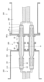
- FIG. 4 is a diagram showing a state in which a bushing according to Embodiment 2 is installed between an oil-insulated device and a gas-insulated device.
- the bushing 100 which is the connection device according to the second embodiment, does not have the vent hole 511 formed in the gas side contact portion 51, but has the vent hole 31 formed in the gas side insulating spacer 30. It differs from the bushing 100 according to the first embodiment.
- the vent hole 31 penetrates the gas side insulating spacer 30 , and the inside and outside of the bushing tank 10 are connected through the vent hole 31 .
- the bushing 100 according to the second embodiment has the gas-side insulating spacer 30 formed with the vent hole 31, the inside of the bushing tank 10 is It becomes the same gas division as in the gas insulation equipment tank 301 . Therefore, like the bushing 100 according to the first embodiment, there is no need to provide sensors for detecting the gas pressure of the insulating gas 302 inside the bushing tank 10 . Further, in the bushing 100 according to the second embodiment, similarly to the bushing 100 according to the first embodiment, the bushing caused by flashover can be prevented without increasing the volume of the bushing tank 10 or installing a pressure relief device. Damage to the tank 10 can be prevented. At least one vent hole 31 may be formed in the gas-side insulating spacer 30 .
- the configuration shown in the above embodiment shows an example of the contents, and it is possible to combine it with another known technique, and part of the configuration is omitted or changed without departing from the scope. is also possible.
Landscapes
- Engineering & Computer Science (AREA)
- Power Engineering (AREA)
- Gas-Insulated Switchgears (AREA)
- Insulators (AREA)
Abstract
油絶縁機器とガス絶縁機器との間に設置されて、油絶縁機器の内部導体とガス絶縁機器の内部導体とを電気的に接続するブッシング(100)であって、筒状のブッシングタンク(10)と、ブッシングタンク(10)の一端に設置された筒状のガス側絶縁スペーサ(30)と、ブッシングタンク(10)の他端に設置された筒状の油側絶縁スペーサ(40)と、ガス側絶縁スペーサ(30)、ブッシングタンク(10)及び油側絶縁スペーサ(40)を貫通し、一端部であるガス側接点部(51)がガス側絶縁スペーサ(30)からブッシングタンク(10)の軸方向に突出し、他端部である油側接点部(52)が油側絶縁スペーサ(40)からブッシングタンク(10)の軸方向に突出した中心導体(50)とを備え、ガス側接点部(51)には、ブッシングタンク(10)の内外を繋ぐ通気孔(511)が形成されている。
Description
本開示は、油絶縁機器とガス絶縁機器とを接続する接続装置に関する。
従来、油絶縁機器とガス絶縁機器とを接続するにあたっては、特許文献1に開示されるようなブッシングとも称される接続装置が用いられている。ブッシングは、筒状のブッシングタンク内に中心導体を収容した密閉構造であり、ブッシングタンクの内部には絶縁ガスが充填される。ブッシングを使用するにあたっては、ブッシングタンク内部の絶縁ガスのガス圧を監視することにより、ガス漏れなどの異常を検知する方法が広く用いられている。
密閉構造のブッシングは、ブッシングタンク内の絶縁ガスのガス圧を監視するためのセンサ類が必要である。また、ブッシングタンク内で閃絡が発生した際の内圧上昇に耐えられるようにするためには、ブッシングタンクの容積を大きくしたり、放圧装置を設けたりする必要があり、部品点数の低減と小型化との両立が困難であった。
本開示は、上記に鑑みてなされたものであって、油絶縁機器とガス絶縁機器とを接続可能であり、部品点数の低減及び小型化を図った接続装置を得ることを目的とする。
上述した課題を解決し、目的を達成するために、本開示に係る接続装置は、油絶縁機器とガス絶縁機器との間に設置されて、油絶縁機器の内部導体とガス絶縁機器の内部導体とを電気的に接続する接続装置であって、筒状のブッシングタンクと、ブッシングタンクの一端に設置された筒状のガス側絶縁スペーサと、ブッシングタンクの他端に設置された筒状の油側絶縁スペーサと、ガス側絶縁スペーサ、ブッシングタンク及び油側絶縁スペーサを貫通し、一端部であるガス側接点部がガス側絶縁スペーサからブッシングタンクの軸方向に突出し、他端部である油側接点部が油側絶縁スペーサからブッシングタンクの軸方向に突出した中心導体とを備える。ガス側接点部又はガス側絶縁スペーサには、ブッシングタンクの内外を繋ぐ通気孔が形成されている。
本開示に係る接続装置によれば、油絶縁機器とガス絶縁機器とを接続可能であり、部品点数の低減及び小型化を図れる、という効果を奏する。
以下に、実施の形態に係る接続装置を図面に基づいて詳細に説明する。
実施の形態1.
図1は、実施の形態1に係るブッシングの構成を示す断面図である。実施の形態1に係る接続装置であるブッシング100は、筒状のブッシングタンク10と、ブッシングタンク10の一端に設置されたスペーサリング20と、スペーサリング20に固定された筒状のガス側絶縁スペーサ30と、ブッシングタンク10の他端に設置された筒状の油側絶縁スペーサ40と、ガス側絶縁スペーサ30、スペーサリング20、ブッシングタンク10及び油側絶縁スペーサ40を貫通する中心導体50とを備える。油側絶縁スペーサ40及びガス側絶縁スペーサ30は、樹脂を材料に用いて形成できる。また、ブッシングタンク10及び中心導体50は、アルミニウムを材料に用いて形成できる。なお、油側絶縁スペーサ40、ガス側絶縁スペーサ30、ブッシングタンク10及び中心導体50は、例示した材料とは異なる材料を用いて形成してもよい。
図1は、実施の形態1に係るブッシングの構成を示す断面図である。実施の形態1に係る接続装置であるブッシング100は、筒状のブッシングタンク10と、ブッシングタンク10の一端に設置されたスペーサリング20と、スペーサリング20に固定された筒状のガス側絶縁スペーサ30と、ブッシングタンク10の他端に設置された筒状の油側絶縁スペーサ40と、ガス側絶縁スペーサ30、スペーサリング20、ブッシングタンク10及び油側絶縁スペーサ40を貫通する中心導体50とを備える。油側絶縁スペーサ40及びガス側絶縁スペーサ30は、樹脂を材料に用いて形成できる。また、ブッシングタンク10及び中心導体50は、アルミニウムを材料に用いて形成できる。なお、油側絶縁スペーサ40、ガス側絶縁スペーサ30、ブッシングタンク10及び中心導体50は、例示した材料とは異なる材料を用いて形成してもよい。
ブッシングタンク10の一端部にはフランジ11が形成されており、スペーサリング20はフランジ11に固定されている。フランジ11及びスペーサリング20には、それぞれ貫通孔111,21が形成されている。貫通孔111と貫通孔21とは、ブッシングタンク10の軸方向に繋がっている。ブッシングタンク10の他端部にはフランジ12が形成されており、油側絶縁スペーサ40はフランジ12に固定されている。また、ブッシングタンク10は、一端部と他端部との間に中間フランジ13が形成されている。なお、中心導体50と油側絶縁スペーサ40との間、及び油側絶縁スペーサ40とブッシングタンク10との間には油シール部材が設置されるが、図示を省略している。また、スペーサリング20とガス側絶縁スペーサ30との間にはガスシール部材が設置されるが、図示を省略している。
中心導体50のうち、ガス側絶縁スペーサ30からブッシングタンク10の軸方向に突出する一端部は、ガス絶縁機器の内部導体に接続されるガス側接点部51となっている。中心導体50のうち、油側絶縁スペーサ40からブッシングタンク10の軸方向に突出する他端部は、油絶縁機器の内部導体に接続される油側接点部52となっている。
図2は、実施の形態1に係るブッシングのガス側接点部の断面図である。図2は、図1中のII-II線に沿った断面を示している。ガス側接点部51には、複数の通気孔511が形成されている。複数の通気孔511は、ガス側接点部51の中心から放射状に伸びる第1の通気孔511aと、ブッシングタンク10の軸方向に伸びる第2の通気孔511bとを含み、第1の通気孔511aと第2の通気孔511bとは繋がっている。複数の通気孔511は、ガス側接点部51を貫通しており、ブッシングタンク10の内外は通気孔511を通じて繋がっている。
なお、ここではガス側接点部51に通気孔511が複数形成されている構成を例に挙げたが、通気孔511はガス側接点部51に少なくとも一つ形成されていればよい。
図3は、実施の形態1に係るブッシングを油絶縁機器とガス絶縁機器との間に設置した状態を示す図である。ブッシング100は、油絶縁機器200とガス絶縁機器300との間に設置され、油絶縁機器200の内部導体210とガス絶縁機器300の内部導体310とを電気的に接続する。油絶縁機器200の油絶縁機器タンク201内には、絶縁油202が封入されている。ガス絶縁機器300のガス絶縁機器タンク301内には、SF6といった絶縁ガス302が封入されている。なお、図示は省略するが、ガス絶縁機器300は、ガス絶縁機器タンク301内の絶縁ガス302のガス圧を検出するセンサを備えている。
ブッシング100は、ガス側絶縁スペーサ30及びガス側接点部51がガス絶縁機器タンク301内に挿入されている。スペーサリング20は、ガス絶縁機器タンク301の端面板301aに突き当てられている。フランジ11の貫通孔111及びスペーサリング20の貫通孔21を貫通させた不図示のボルトが端面板301aにねじ止めされることによって、ブッシング100はガス絶縁機器300に固定されている。
また、ブッシング100は、油側接点部52、油側絶縁スペーサ40及びブッシングタンク10の他端部側の一部分が油絶縁機器タンク201内に挿入されている。油絶縁機器タンク201の端面板201aにはスペーサリング60を介してベローズ70が固定されており、ブッシング100はベローズ70の筒内を通して油絶縁機器タンク201内に挿入されている。ベローズ70は、スペーサリング60と中間フランジ13とに挟まれており、油側接点部52が油絶縁機器タンク201内の内部導体210に突き当たるとベローズ70が縮むようになっている。ベローズ70が縮み始めるまでブッシング100を油絶縁機器タンク201内に挿入することにより、油側接点部52を確実に油絶縁機器タンク201内の内部導体210に接触させることができる。なお、端面板201aとスペーサリング60との間、スペーサリング60とベローズ70との間及びベローズ70と中間フランジ13との間には、油シール部材が配置されるが図示を省略している。
実施の形態1に係るブッシング100は、ガス側接点部51に通気孔511が形成されているため、油絶縁機器200とガス絶縁機器300との間に設置した際にブッシングタンク10の内部は、ガス絶縁機器タンク301内と同じガス区分となり、ブッシングタンク10内には絶縁ガス302が流入する。このため、ブッシングタンク10内の絶縁ガス302のガス圧は、ガス絶縁機器タンク301内の絶縁ガス302のガス圧と同じである。したがって、ブッシングタンク10内には絶縁ガス302のガス圧を検出するセンサ類を設ける必要がなく、部品点数を低減することができる。また、ブッシングタンク10内で閃絡が発生したことによる発熱でブッシングタンク10内の絶縁ガス302が膨張しても、通気孔511を通じてブッシングタンク10内の絶縁ガス302をガス絶縁機器タンク301内に放出し、ブッシングタンク10内の絶縁ガス302のガス圧の上昇を抑えることができる。したがって、ブッシングタンク10の容積を大きくしたり、放圧装置を設置したりすることなく、閃絡に起因するブッシングタンク10の破損を防止できる。このため、実施の形態1に係るブッシング100は、小型化が可能である。
実施の形態2.
図4は、実施の形態2に係るブッシングを油絶縁機器とガス絶縁機器との間に設置した状態を示す図である。実施の形態2に係る接続装置であるブッシング100は、ガス側接点部51には通気孔511が形成されておらず、ガス側絶縁スペーサ30に通気孔31が形成されている点で、実施の形態1に係るブッシング100と相違する。通気孔31は、ガス側絶縁スペーサ30を貫通しており、ブッシングタンク10の内外は、通気孔31を通じて繋がっている。
図4は、実施の形態2に係るブッシングを油絶縁機器とガス絶縁機器との間に設置した状態を示す図である。実施の形態2に係る接続装置であるブッシング100は、ガス側接点部51には通気孔511が形成されておらず、ガス側絶縁スペーサ30に通気孔31が形成されている点で、実施の形態1に係るブッシング100と相違する。通気孔31は、ガス側絶縁スペーサ30を貫通しており、ブッシングタンク10の内外は、通気孔31を通じて繋がっている。
実施の形態2に係るブッシング100は、ガス側絶縁スペーサ30に通気孔31が形成されているため、油絶縁機器200とガス絶縁機器300との間に設置した際にブッシングタンク10の内部は、ガス絶縁機器タンク301内と同じガス区分となる。したがって、実施の形態1に係るブッシング100と同様に、ブッシングタンク10内には絶縁ガス302のガス圧を検出するセンサ類を設ける必要がない。また、実施の形態2に係るブッシング100は、実施の形態1に係るブッシング100と同様に、ブッシングタンク10の容積を大きくしたり、放圧装置設置したりすることなく、閃絡に起因するブッシングタンク10の破損を防止できる。なお、通気孔31は、ガス側絶縁スペーサ30に少なくとも一つ形成されていればよい。
以上の実施の形態に示した構成は、内容の一例を示すものであり、別の公知の技術と組み合わせることも可能であるし、要旨を逸脱しない範囲で、構成の一部を省略、変更することも可能である。
10 ブッシングタンク、11,12 フランジ、13 中間フランジ、20,60 スペーサリング、21,111 貫通孔、30 ガス側絶縁スペーサ、31,511 通気孔、40 油側絶縁スペーサ、50 中心導体、51 ガス側接点部、52 油側接点部、70 ベローズ、100 ブッシング、200 油絶縁機器、201 油絶縁機器タンク、201a,301a 端面板、202 絶縁油、210,310 内部導体、300 ガス絶縁機器、301 ガス絶縁機器タンク、302 絶縁ガス、511a 第1の通気孔、511b 第2の通気孔。
Claims (2)
- 油絶縁機器とガス絶縁機器との間に設置されて、前記油絶縁機器の内部導体と前記ガス絶縁機器の内部導体とを電気的に接続する接続装置であって、
筒状のブッシングタンクと、
前記ブッシングタンクの一端に設置された筒状のガス側絶縁スペーサと、
前記ブッシングタンクの他端に設置された筒状の油側絶縁スペーサと、
前記ガス側絶縁スペーサ、前記ブッシングタンク及び前記油側絶縁スペーサを貫通し、一端部であるガス側接点部が前記ガス側絶縁スペーサから前記ブッシングタンクの軸方向に突出し、他端部である油側接点部が前記油側絶縁スペーサから前記ブッシングタンクの軸方向に突出した中心導体とを備え、
前記ガス側接点部又は前記ガス側絶縁スペーサには、前記ブッシングタンクの内外を繋ぐ通気孔が形成されていることを特徴とする接続装置。 - 前記通気孔が複数形成されていることを特徴とする請求項1に記載の接続装置。
Priority Applications (2)
| Application Number | Priority Date | Filing Date | Title |
|---|---|---|---|
| JP2022523036A JP7376709B1 (ja) | 2022-01-25 | 2022-01-25 | 接続装置 |
| PCT/JP2022/002603 WO2023144875A1 (ja) | 2022-01-25 | 2022-01-25 | 接続装置 |
Applications Claiming Priority (1)
| Application Number | Priority Date | Filing Date | Title |
|---|---|---|---|
| PCT/JP2022/002603 WO2023144875A1 (ja) | 2022-01-25 | 2022-01-25 | 接続装置 |
Publications (1)
| Publication Number | Publication Date |
|---|---|
| WO2023144875A1 true WO2023144875A1 (ja) | 2023-08-03 |
Family
ID=87471163
Family Applications (1)
| Application Number | Title | Priority Date | Filing Date |
|---|---|---|---|
| PCT/JP2022/002603 Ceased WO2023144875A1 (ja) | 2022-01-25 | 2022-01-25 | 接続装置 |
Country Status (2)
| Country | Link |
|---|---|
| JP (1) | JP7376709B1 (ja) |
| WO (1) | WO2023144875A1 (ja) |
Citations (4)
| Publication number | Priority date | Publication date | Assignee | Title |
|---|---|---|---|---|
| JPS5828812A (ja) * | 1981-08-12 | 1983-02-19 | Nissin Electric Co Ltd | 油入電気機器とガス入電気機器との接続装置 |
| JPS62155707A (ja) * | 1985-12-27 | 1987-07-10 | 株式会社東芝 | 電気機器装置 |
| JP2013240141A (ja) * | 2012-05-11 | 2013-11-28 | Mitsubishi Electric Corp | 接続装置 |
| JP2015191921A (ja) * | 2014-03-27 | 2015-11-02 | 三菱電機株式会社 | 油ガススペーサおよび油絶縁機器 |
Family Cites Families (2)
| Publication number | Priority date | Publication date | Assignee | Title |
|---|---|---|---|---|
| JP4202075B2 (ja) * | 2002-09-09 | 2008-12-24 | 中部電力株式会社 | ガス絶縁電気機器のスペーサ |
| JP5114331B2 (ja) * | 2008-07-23 | 2013-01-09 | 株式会社日立製作所 | 電気機器のガス−油直結三相一括型絶縁区分装置 |
-
2022
- 2022-01-25 WO PCT/JP2022/002603 patent/WO2023144875A1/ja not_active Ceased
- 2022-01-25 JP JP2022523036A patent/JP7376709B1/ja active Active
Patent Citations (4)
| Publication number | Priority date | Publication date | Assignee | Title |
|---|---|---|---|---|
| JPS5828812A (ja) * | 1981-08-12 | 1983-02-19 | Nissin Electric Co Ltd | 油入電気機器とガス入電気機器との接続装置 |
| JPS62155707A (ja) * | 1985-12-27 | 1987-07-10 | 株式会社東芝 | 電気機器装置 |
| JP2013240141A (ja) * | 2012-05-11 | 2013-11-28 | Mitsubishi Electric Corp | 接続装置 |
| JP2015191921A (ja) * | 2014-03-27 | 2015-11-02 | 三菱電機株式会社 | 油ガススペーサおよび油絶縁機器 |
Also Published As
| Publication number | Publication date |
|---|---|
| JP7376709B1 (ja) | 2023-11-08 |
| JPWO2023144875A1 (ja) | 2023-08-03 |
Similar Documents
| Publication | Publication Date | Title |
|---|---|---|
| CN1152243C (zh) | 压力传感器模块的预先组装 | |
| CN111255945B (zh) | 一种阀杆密封结构及阀门 | |
| US8816197B2 (en) | Pressure balanced connector termination | |
| US9601240B2 (en) | High-voltage insulator | |
| US8367935B2 (en) | Electrical power connection device | |
| EP3048619B1 (en) | Pressure compensator for subsea device | |
| US11018485B2 (en) | Explosion-proof structure | |
| CN103403834A (zh) | 海底熔断器组件 | |
| EP3057111A1 (en) | Pressure compensator and method of manufacturing a pressure compensator | |
| CN101876375B (zh) | 密封装置 | |
| CN213394022U (zh) | 用于气体绝缘设备的法兰组件以及气体绝缘设备 | |
| CN101933208A (zh) | 有封闭外壳的装置 | |
| CN100368720C (zh) | 缆线引入和管子穿过用的套筒 | |
| WO2023144875A1 (ja) | 接続装置 | |
| EP2117016A1 (en) | Draw rod mounting arrangement for a high voltage bushing, high voltage bushing comprising such arrangement and high voltage device comprising bushing with such arrangement | |
| US11415437B2 (en) | Sensor | |
| WO2023286112A1 (ja) | 真空遮断器 | |
| CN213451666U (zh) | 一种气体绝缘高压电器设备用高气密性密封结构 | |
| US20230366489A1 (en) | Device for guiding a line through a wall in a pressure-tight manner, and method for producing the device | |
| CN208539181U (zh) | 一种高压力差的电连接器 | |
| KR101600892B1 (ko) | 전기 관통구 집합체 | |
| US3869561A (en) | Cable separating joint | |
| WO2023113997A1 (en) | Electrical coupling | |
| CN114320208A (zh) | 一种气井井口可视化装置的自紧密封结构 | |
| CN107191594A (zh) | 水下密封装置 |
Legal Events
| Date | Code | Title | Description |
|---|---|---|---|
| WWE | Wipo information: entry into national phase |
Ref document number: 2022523036 Country of ref document: JP |
|
| 121 | Ep: the epo has been informed by wipo that ep was designated in this application |
Ref document number: 22923744 Country of ref document: EP Kind code of ref document: A1 |
|
| NENP | Non-entry into the national phase |
Ref country code: DE |
|
| 122 | Ep: pct application non-entry in european phase |
Ref document number: 22923744 Country of ref document: EP Kind code of ref document: A1 |