WO2023140183A1 - ガスタービン燃焼器の制御方法及びガスタービン燃焼器の制御装置 - Google Patents
ガスタービン燃焼器の制御方法及びガスタービン燃焼器の制御装置 Download PDFInfo
- Publication number
- WO2023140183A1 WO2023140183A1 PCT/JP2023/000738 JP2023000738W WO2023140183A1 WO 2023140183 A1 WO2023140183 A1 WO 2023140183A1 JP 2023000738 W JP2023000738 W JP 2023000738W WO 2023140183 A1 WO2023140183 A1 WO 2023140183A1
- Authority
- WO
- WIPO (PCT)
- Prior art keywords
- fuel
- gas turbine
- turbine combustor
- hydrogen
- air holes
- Prior art date
- Legal status (The legal status is an assumption and is not a legal conclusion. Google has not performed a legal analysis and makes no representation as to the accuracy of the status listed.)
- Ceased
Links
Images




Classifications
-
- F—MECHANICAL ENGINEERING; LIGHTING; HEATING; WEAPONS; BLASTING
- F02—COMBUSTION ENGINES; HOT-GAS OR COMBUSTION-PRODUCT ENGINE PLANTS
- F02C—GAS-TURBINE PLANTS; AIR INTAKES FOR JET-PROPULSION PLANTS; CONTROLLING FUEL SUPPLY IN AIR-BREATHING JET-PROPULSION PLANTS
- F02C9/00—Controlling gas-turbine plants; Controlling fuel supply in air- breathing jet-propulsion plants
- F02C9/26—Control of fuel supply
- F02C9/40—Control of fuel supply specially adapted to the use of a special fuel or a plurality of fuels
-
- F—MECHANICAL ENGINEERING; LIGHTING; HEATING; WEAPONS; BLASTING
- F02—COMBUSTION ENGINES; HOT-GAS OR COMBUSTION-PRODUCT ENGINE PLANTS
- F02C—GAS-TURBINE PLANTS; AIR INTAKES FOR JET-PROPULSION PLANTS; CONTROLLING FUEL SUPPLY IN AIR-BREATHING JET-PROPULSION PLANTS
- F02C3/00—Gas-turbine plants characterised by the use of combustion products as the working fluid
- F02C3/20—Gas-turbine plants characterised by the use of combustion products as the working fluid using a special fuel, oxidant, or dilution fluid to generate the combustion products
-
- F—MECHANICAL ENGINEERING; LIGHTING; HEATING; WEAPONS; BLASTING
- F02—COMBUSTION ENGINES; HOT-GAS OR COMBUSTION-PRODUCT ENGINE PLANTS
- F02C—GAS-TURBINE PLANTS; AIR INTAKES FOR JET-PROPULSION PLANTS; CONTROLLING FUEL SUPPLY IN AIR-BREATHING JET-PROPULSION PLANTS
- F02C3/00—Gas-turbine plants characterised by the use of combustion products as the working fluid
- F02C3/20—Gas-turbine plants characterised by the use of combustion products as the working fluid using a special fuel, oxidant, or dilution fluid to generate the combustion products
- F02C3/22—Gas-turbine plants characterised by the use of combustion products as the working fluid using a special fuel, oxidant, or dilution fluid to generate the combustion products the fuel or oxidant being gaseous at standard temperature and pressure
-
- F—MECHANICAL ENGINEERING; LIGHTING; HEATING; WEAPONS; BLASTING
- F02—COMBUSTION ENGINES; HOT-GAS OR COMBUSTION-PRODUCT ENGINE PLANTS
- F02C—GAS-TURBINE PLANTS; AIR INTAKES FOR JET-PROPULSION PLANTS; CONTROLLING FUEL SUPPLY IN AIR-BREATHING JET-PROPULSION PLANTS
- F02C7/00—Features, components parts, details or accessories, not provided for in, or of interest apart form groups F02C1/00 - F02C6/00; Air intakes for jet-propulsion plants
- F02C7/22—Fuel supply systems
- F02C7/228—Dividing fuel between various burners
-
- F—MECHANICAL ENGINEERING; LIGHTING; HEATING; WEAPONS; BLASTING
- F02—COMBUSTION ENGINES; HOT-GAS OR COMBUSTION-PRODUCT ENGINE PLANTS
- F02C—GAS-TURBINE PLANTS; AIR INTAKES FOR JET-PROPULSION PLANTS; CONTROLLING FUEL SUPPLY IN AIR-BREATHING JET-PROPULSION PLANTS
- F02C7/00—Features, components parts, details or accessories, not provided for in, or of interest apart form groups F02C1/00 - F02C6/00; Air intakes for jet-propulsion plants
- F02C7/22—Fuel supply systems
- F02C7/232—Fuel valves; Draining valves or systems
-
- F—MECHANICAL ENGINEERING; LIGHTING; HEATING; WEAPONS; BLASTING
- F02—COMBUSTION ENGINES; HOT-GAS OR COMBUSTION-PRODUCT ENGINE PLANTS
- F02C—GAS-TURBINE PLANTS; AIR INTAKES FOR JET-PROPULSION PLANTS; CONTROLLING FUEL SUPPLY IN AIR-BREATHING JET-PROPULSION PLANTS
- F02C9/00—Controlling gas-turbine plants; Controlling fuel supply in air- breathing jet-propulsion plants
- F02C9/26—Control of fuel supply
- F02C9/263—Control of fuel supply by means of fuel metering valves
-
- F—MECHANICAL ENGINEERING; LIGHTING; HEATING; WEAPONS; BLASTING
- F02—COMBUSTION ENGINES; HOT-GAS OR COMBUSTION-PRODUCT ENGINE PLANTS
- F02C—GAS-TURBINE PLANTS; AIR INTAKES FOR JET-PROPULSION PLANTS; CONTROLLING FUEL SUPPLY IN AIR-BREATHING JET-PROPULSION PLANTS
- F02C9/00—Controlling gas-turbine plants; Controlling fuel supply in air- breathing jet-propulsion plants
- F02C9/26—Control of fuel supply
- F02C9/32—Control of fuel supply characterised by throttling of fuel
-
- F—MECHANICAL ENGINEERING; LIGHTING; HEATING; WEAPONS; BLASTING
- F23—COMBUSTION APPARATUS; COMBUSTION PROCESSES
- F23C—METHODS OR APPARATUS FOR COMBUSTION USING FLUID FUEL OR SOLID FUEL SUSPENDED IN A CARRIER GAS OR AIR
- F23C1/00—Combustion apparatus specially adapted for combustion of two or more kinds of fuel simultaneously or alternately, at least one kind of fuel being either a fluid fuel or a solid fuel suspended in a carrier gas or air
-
- F—MECHANICAL ENGINEERING; LIGHTING; HEATING; WEAPONS; BLASTING
- F23—COMBUSTION APPARATUS; COMBUSTION PROCESSES
- F23N—REGULATING OR CONTROLLING COMBUSTION
- F23N1/00—Regulating fuel supply
- F23N1/002—Regulating fuel supply using electronic means
-
- F—MECHANICAL ENGINEERING; LIGHTING; HEATING; WEAPONS; BLASTING
- F23—COMBUSTION APPARATUS; COMBUSTION PROCESSES
- F23R—GENERATING COMBUSTION PRODUCTS OF HIGH PRESSURE OR HIGH VELOCITY, e.g. GAS-TURBINE COMBUSTION CHAMBERS
- F23R3/00—Continuous combustion chambers using liquid or gaseous fuel
- F23R3/28—Continuous combustion chambers using liquid or gaseous fuel characterised by the fuel supply
- F23R3/286—Continuous combustion chambers using liquid or gaseous fuel characterised by the fuel supply having fuel-air premixing devices
-
- F—MECHANICAL ENGINEERING; LIGHTING; HEATING; WEAPONS; BLASTING
- F23—COMBUSTION APPARATUS; COMBUSTION PROCESSES
- F23R—GENERATING COMBUSTION PRODUCTS OF HIGH PRESSURE OR HIGH VELOCITY, e.g. GAS-TURBINE COMBUSTION CHAMBERS
- F23R3/00—Continuous combustion chambers using liquid or gaseous fuel
- F23R3/28—Continuous combustion chambers using liquid or gaseous fuel characterised by the fuel supply
- F23R3/34—Feeding into different combustion zones
-
- F—MECHANICAL ENGINEERING; LIGHTING; HEATING; WEAPONS; BLASTING
- F23—COMBUSTION APPARATUS; COMBUSTION PROCESSES
- F23R—GENERATING COMBUSTION PRODUCTS OF HIGH PRESSURE OR HIGH VELOCITY, e.g. GAS-TURBINE COMBUSTION CHAMBERS
- F23R3/00—Continuous combustion chambers using liquid or gaseous fuel
- F23R3/28—Continuous combustion chambers using liquid or gaseous fuel characterised by the fuel supply
- F23R3/36—Supply of different fuels
-
- F—MECHANICAL ENGINEERING; LIGHTING; HEATING; WEAPONS; BLASTING
- F23—COMBUSTION APPARATUS; COMBUSTION PROCESSES
- F23C—METHODS OR APPARATUS FOR COMBUSTION USING FLUID FUEL OR SOLID FUEL SUSPENDED IN A CARRIER GAS OR AIR
- F23C2900/00—Special features of, or arrangements for combustion apparatus using fluid fuels or solid fuels suspended in air; Combustion processes therefor
- F23C2900/9901—Combustion process using hydrogen, hydrogen peroxide water or brown gas as fuel
-
- F—MECHANICAL ENGINEERING; LIGHTING; HEATING; WEAPONS; BLASTING
- F23—COMBUSTION APPARATUS; COMBUSTION PROCESSES
- F23R—GENERATING COMBUSTION PRODUCTS OF HIGH PRESSURE OR HIGH VELOCITY, e.g. GAS-TURBINE COMBUSTION CHAMBERS
- F23R3/00—Continuous combustion chambers using liquid or gaseous fuel
- F23R3/28—Continuous combustion chambers using liquid or gaseous fuel characterised by the fuel supply
Definitions
- the present disclosure relates to a gas turbine combustor control method and a gas turbine combustor control apparatus.
- This application claims priority based on Japanese Patent Application No. 2022-006878 filed with the Japan Patent Office on January 20, 2022, the content of which is incorporated herein.
- a gas turbine combustor in which an air hole plate is arranged between a fuel nozzle and a combustion chamber, and a fuel flow and an air flow formed on the outer peripheral side of the fuel flow are ejected into the combustion chamber inside the air holes provided in the air hole plate (see, for example, Patent Document 1).
- At least one embodiment of the present disclosure aims to suppress damage to a gas turbine combustor that burns hydrogen fuel and fuels other than hydrogen fuel.
- a gas turbine combustor control method includes: A control method for a gas turbine combustor that includes an air hole plate in which a plurality of air holes are formed and a plurality of fuel nozzles corresponding to the plurality of air holes, and that burns hydrogen fuel and other fuels other than hydrogen fuel, the method comprising:
- the plurality of air holes are a plurality of first air holes having inclined passages extending in a direction inclined with respect to the central axis of the air hole plate in a region including at least the outlet end among the passages between the inlet end and the outlet end; a plurality of second air holes extending parallel to the central axis; including
- the plurality of fuel nozzles are a plurality of first fuel nozzles respectively corresponding to the plurality of first air holes; a plurality of second fuel nozzles respectively corresponding to the plurality of second air holes; including
- the hydrogen fuel is not supplied to the plurality of first fuel nozzles during the hydrogen fuel mono-firing.
- a control device for controlling combustion in a gas turbine combustor that includes an air hole plate in which a plurality of air holes are formed and a plurality of fuel nozzles corresponding to each of the plurality of air holes, and that burns hydrogen fuel and other fuels other than hydrogen fuel
- the plurality of air holes are a plurality of first air holes having inclined passages extending in a direction inclined with respect to the central axis of the air hole plate in a region including at least the outlet end among the passages between the inlet end and the outlet end; a plurality of second air holes extending parallel to the central axis; including
- the plurality of fuel nozzles are a plurality of first fuel nozzles respectively corresponding to the plurality of first air holes; a plurality of second fuel nozzles respectively corresponding to the plurality of second air holes; including a fuel flow control valve that adjusts the flow rate of fuel supplied to the plurality of first fuel nozzles;
- damage to a gas turbine combustor that burns hydrogen fuel and other fuels other than hydrogen fuel can be suppressed.
- FIG. 1 shows a schematic configuration of a gas turbine with a gas turbine combustor according to some embodiments
- 2 is a schematic partial cross-sectional view showing a structure near a burner in a gas turbine combustor according to one embodiment provided in the gas turbine shown in FIG. 1
- FIG. FIG. 3 is a schematic partial cross-sectional view showing a structure near a burner in a gas turbine combustor according to another embodiment provided in the gas turbine shown in FIG. 1
- 2B is an axially downstream view of the air hole plate of the burner according to the embodiment shown in FIG. 2A
- FIG. FIG. 2C is an axially downstream view of the air hole plate of the burner according to another embodiment shown in FIG.
- FIG. 10 is a diagram showing another example of a first air hole among the air holes
- FIG. 3B is a diagram for explaining the control of the combustion injection ratio based on the hydrogen co-firing ratio in the gas turbine combustor according to the embodiment shown in FIGS. 2A and 3A
- FIG. 3C is a diagram for explaining control of the combustion injection ratio based on the hydrogen co-firing ratio in the gas turbine combustor according to another embodiment shown in FIGS. 2B and 3B
- FIG. 3B is a graph showing changes in fuel ratio and hydrogen co-firing ratio from the start of operation of the gas turbine having the gas turbine combustor according to the embodiment shown in FIGS.
- FIG. 3C is a graph showing changes in the fuel ratio and the hydrogen co-firing ratio from the start of operation of the gas turbine having the gas turbine combustor according to another embodiment shown in FIGS. 2B and 3B to transition to mono-firing of hydrogen fuel.
- expressions such as “same,””equal,” and “homogeneous” that indicate that things are in the same state not only indicate the state of being strictly equal, but also the state in which there is a tolerance or a difference to the extent that the same function can be obtained.
- the expression representing a shape such as a square shape or a cylindrical shape not only represents a shape such as a square shape or a cylindrical shape in a geometrically strict sense, but also represents a shape including an uneven part, a chamfered part, etc. to the extent that the same effect can be obtained.
- the expressions “comprising”, “comprising”, “having”, “including”, or “having” one component are not exclusive expressions excluding the presence of other components.
- FIG. 1 shows a schematic configuration of a gas turbine with gas turbine combustors according to some embodiments of the present disclosure.
- a gas turbine 1 shown in FIG. 1 includes an air compressor 110 , a gas turbine combustor 100 and a turbine 180 .
- a gas turbine combustor 100 includes a combustor liner (inner cylinder) 153, a liner flow sleeve (outer cylinder) 154, a transition piece 152, a transition piece flow sleeve 150, a burner 200, a fuel system 300, and a control device 10 (see FIGS. 2A and 2B).
- FIG. 1 shows the burner 200 and the fuel system 300 in a simplified manner, and shows only one fuel header 230 and one fuel supply pipe 305, which will be described later. Note that the burner 200 and the fuel system 300 will be described later.
- the air compressor 110 is rotationally driven by the turbine 180, compresses air (intake air) sucked from the atmosphere through an intake section (not shown), generates high-pressure air (combustion air) 120, and supplies it to the gas turbine combustor 100.
- Gas turbine combustor 100 mixes and burns high-pressure air 120 supplied from air compressor 110 with fuel supplied from fuel system 300 to generate high-temperature combustion gas 170 and supplies it to turbine 180 .
- high-pressure air 120 which is combustion air discharged from the air compressor 110, is introduced from the diffuser 130 into the casing 140, and flows through the air introduction hole 151 provided in the transition piece flow sleeve 150 of the gas turbine combustor 100 into the flow path formed in the gap between the transition piece flow sleeve 150 and the transition piece 152 disposed inside the transition piece flow sleeve 150.
- the high-pressure air 120 that has flowed into the flow path formed in this gap then flows through the flow path formed in the gap between the combustor liner 153 of the gas turbine combustor 100 and the liner flow sleeve 154 that is arranged concentrically with the combustor liner 153 on the outer peripheral side of the combustor liner 153, reverses the flow, and mixes with the fuel that is introduced from the fuel system 300 and injected from the plurality of fuel nozzles 210 that constitute the cluster nozzles.
- Combustion chamber 160 inside 153 forms flame 156 and generates high temperature and high pressure combustion gas 170 .
- the amount of work generated when the high-temperature, high-pressure combustion gas 170 introduced into the turbine 180 undergoes adiabatic expansion is converted into shaft rotational force by the turbine 180, thereby driving the generator 190 connected to the turbine 180 via the turbine shaft and obtaining output from the generator 190.
- the air compressor 110 and the generator 190 that constitute the gas turbine 1 are connected to the turbine 180 by a turbine shaft.
- the air compressor 110, the turbine 180, and the generator 190 may have two or more turbine shafts instead of one.
- gas turbines which are widely used in thermal power plants and the like, have a configuration in which multiple gas turbine combustors are arranged radially with respect to the turbine shaft.
- FIG. 2A is a schematic partial cross-sectional view showing a structure around a burner 200 in a gas turbine combustor 100 according to one embodiment provided in the gas turbine 1 shown in FIG. 1.
- FIG. 2B is a schematic partial cross-sectional view showing the structure around the burner 200 in the gas turbine combustor 100 according to another embodiment provided in the gas turbine 1 shown in FIG.
- FIG. 3A is an axially downstream view of the air hole plate 25 of the burner 200 according to the embodiment shown in FIG. 2A.
- FIG. 3B is an axially downstream view of the air hole plate 25 of the burner 200 according to another embodiment shown in FIG. 2B.
- the direction along the central axis AXc of the gas turbine combustor 100 is also referred to as the axial direction of the gas turbine combustor 100 or simply the axial direction.
- the direction in which the combustion gas 170 flows is referred to as the axial downstream side, or simply the downstream side
- the direction opposite to the flow of the combustion gas 170 is referred to as the axial upstream side, or simply the upstream side.
- the central axis AXc of the gas turbine combustor 100 is the central axis of the combustor liner 153 having a cylindrical shape, for example.
- the central axis AXc of the gas turbine combustor 100 is assumed to coincide with the central axis AXp of the air hole plate 25 .
- a gas turbine combustor 100 is a gas turbine combustor capable of combusting hydrogen fuel and fuels other than hydrogen fuel.
- the gas turbine combustor 100 burns natural gas fuel as an alternative fuel.
- the gas turbine combustor 100 according to some embodiments is capable of mono-firing hydrogen fuel, mono-firing natural gas fuel, and co-firing hydrogen fuel and natural gas fuel.
- the burner 200 is arranged perpendicular to the central axis AXc of the gas turbine combustor 100 (the central axis of the combustor liner 153), and is provided at the upstream end of the combustor liner 153 in the axial direction.
- burner 200 includes fuel header 230 , multiple fuel nozzles 210 and air hole plate 25 .
- a gas turbine combustor 100 is a so-called cluster combustor.
- the air hole plate 25 is formed with a plurality of air holes 250 .
- Each of the plurality of fuel nozzles 210 is arranged in one-to-one correspondence with each of the plurality of air holes 250 formed in the air hole plate 25 arranged close to the downstream side of the fuel nozzles 210 in the axial direction. Note that the tip of each fuel nozzle 210 may not be inserted into each of the air holes 250 as shown in FIGS. 2A and 2B, and may be inserted into each of the air holes 250 .
- the burner 200 is a so-called multi-burner including one central burner 211 arranged coaxially with the combustor liner 153 and a plurality of (six in this embodiment) outer burners 212 arranged around the central burner 211.
- the central burners 211 and outer burners 212 are each segmented into a plurality (three in this embodiment) of concentric circular rows.
- the plurality of annular rows of the central burner 211 and the outer burners 212 are appropriately referred to as first row, second row, and third row, respectively, from the inner peripheral side to the outer peripheral side.
- central burner 211 includes fuel header 230 , multiple fuel nozzles 210 , and multiple air holes 250 formed in air hole plate 25 .
- Central burner 211 is supported by fuel header 230 .
- the fuel nozzles 210 of the central burner 211 are arranged concentrically in the first to third rows of the central burner 211, and are provided over the entire circumference of each row (circularly arranged).
- Fuel nozzle 210 of central burner 211 injects fuel supplied from fuel system 300 toward air holes 250 formed in air hole plate 25 .
- the fuel header 230 of the central burner 211 includes an inner fuel header 231 and an outer fuel header 232 that surrounds the inner fuel header 231 in the radial direction.
- the plurality of fuel nozzles 210 of the central burner 211 includes inner fuel nozzles 210i connected to the inner fuel header 231 and outer fuel nozzles 210o connected to the outer fuel header 232.
- the inner peripheral fuel nozzles 210i of the central burner 211 correspond to the first row of fuel nozzles 210
- the outer peripheral fuel nozzles 210o of the central burner 211 correspond to the second and third rows of fuel nozzles 210.
- the air hole plate 25 includes a plurality of inner peripheral air holes 250i corresponding one-to-one with the plurality of inner fuel nozzles 210i of the central burner 211, and a plurality of outer peripheral air holes 250o corresponding one-to-one with the plurality of outer fuel nozzles 210o of the central burner 211.
- the first row of the central burner 211 is composed of the inner fuel header 231, the inner fuel nozzle 210i and the inner air holes 250i, and the second and third rows are composed of the outer fuel header 232, the outer fuel nozzle 210o and the outer air holes 250o.
- outer burner 212 includes fuel header 230 , multiple fuel nozzles 210 , and multiple air holes 250 formed in air hole plate 25 .
- Outer burners 212 are supported in fuel header 230 .
- the fuel nozzles 210 of the outer burners 212 are arranged concentrically in the first to third rows of the outer burners 212, and are provided along the entire circumference of each row (circularly arranged).
- Fuel nozzles 210 of outer burner 212 inject fuel supplied from fuel system 300 toward air holes 250 formed in air hole plate 25 .
- the fuel header 230 of the outer burner 212 includes an inner fuel header 231 and an outer fuel header 232 that radially surrounds the inner fuel header 231 .
- the plurality of fuel nozzles 210 of the outer burner 212 includes inner fuel nozzles 210i connected to the inner fuel header 231 and outer fuel nozzles 210o connected to the outer fuel header 232.
- the inner peripheral fuel nozzles 210i of the outer burners 212 correspond to the first row of fuel nozzles 210
- the outer peripheral fuel nozzles 210o of the outer burners 212 correspond to the second and third rows of fuel nozzles 210.
- the air hole plate 25 includes a plurality of inner peripheral air holes 250i corresponding one-to-one with the plurality of inner fuel nozzles 210i of the outer burner 212, and a plurality of outer peripheral air holes 250o corresponding one-to-one with the plurality of outer fuel nozzles 210o of the outer burner 212.
- the first row of the outer burner 212 is composed of the inner fuel header 231, the inner fuel nozzle 210i and the inner air holes 250i, and the second and third rows are composed of the outer fuel header 232, the outer fuel nozzle 210o and the outer air holes 250o.
- FIG. 4A is a diagram showing an example of the first air holes 251 in the air holes 250.
- FIG. FIG. 4B is a diagram showing another example of the first air holes 251 in the air holes 250.
- the plurality of air holes 250 includes a plurality of first air holes 251 having inclined passages 256 extending in a direction inclined with respect to the central axis AXp of the air hole plate 25 in a region including at least the outlet end 250b of the passages 255 between the inlet end 250a and the outlet end 250b, and parallel to the central axis AXp of the air hole plate 25. and a plurality of second air holes 252 extending to the .
- the inclined passage 256 in the first air hole 251 may be only a portion of the passage 255 on the outlet end 250b side (axial downstream side), and the passage 255 on the inlet end 250a side (axial upstream side) may extend parallel to the central axis AXp of the air hole plate 25. Also, the angled passage 256 in the first air hole 251 may extend from the inlet end 250a to the outlet end 250b, as shown in FIG. 4B.
- the fuel nozzles 210 corresponding to the first air holes 251 are also referred to as the first fuel nozzles 21, and the fuel nozzles 210 corresponding to the second air holes 252 are also referred to as the second fuel nozzles 22.
- the inner peripheral air holes 250 i corresponding to the first row of fuel nozzles 210 of the central burner 211 , ie, the inner peripheral fuel nozzles 210 i are first air holes 251 .
- the inner peripheral air holes 250i of the central burner 211 constitute a first air hole group G1 in which a plurality of first air holes 251 are arranged side by side.
- the first row of fuel nozzles 210 of the central burner 211 i.e., the inner circumference fuel nozzles 210i, is the first fuel nozzle 21.
- the second and third rows of fuel nozzles 210 of the central burner 211 are second air holes 252.
- the outer peripheral air holes 250o of the central burner 211 constitute a second air hole group G2 in which a plurality of second air holes 252 are arranged adjacent to each other.
- the second and third rows of fuel nozzles 210 of the central burner 211 ie, the outer fuel nozzles 210 o are the second fuel nozzles 22 .
- the first, second, and third rows of fuel nozzles 210 of the outer burner 212 i.e., inner air holes 250i corresponding to inner fuel nozzles 210i and outer air holes 250o corresponding to outer fuel nozzles 210o, are second air holes 252.
- the inner peripheral air holes 250i and the outer peripheral air holes 250o of the outer burner 212 constitute the second air hole group G2.
- all fuel nozzles 210 of the outer burner 212 are secondary fuel nozzles 22 .
- the inner peripheral air holes 250 i corresponding to the first row of fuel nozzles 210 of the central burner 211 , ie, the inner peripheral fuel nozzles 210 i are the first air holes 251 .
- the inner peripheral air holes 250i of the central burner 211 constitute the first air hole group G1.
- the first row of fuel nozzles 210 of the central burner 211 i.e. the inner circumference fuel nozzles 210i, is the first fuel nozzle 21.
- the second and third rows of fuel nozzles 210 of the central burner 211 i.e., the outer air holes 250o corresponding to the outer fuel nozzles 210o
- the outer peripheral air holes 250o of the central burner 211 constitute the second air hole group G2.
- the second and third rows of fuel nozzles 210 of the central burner 211 ie, the outer fuel nozzles 210 o
- the inner peripheral air holes 250 i corresponding to the first row of fuel nozzles 210 of the outer burner 212 , ie, the inner peripheral fuel nozzles 210 i are the first air holes 251 .
- the inner peripheral air holes 250i of the outer burner 212 constitute the first air hole group G1.
- the first row of fuel nozzles 210 of the outer burner 212 i.e., the inner circumference fuel nozzles 210i, are the first fuel nozzles 21.
- the second and third rows of fuel nozzles 210 of the outer burner 212 are second air holes 252.
- the outer peripheral air holes 250o of the outer burner 212 constitute the second air hole group G2.
- the second and third rows of fuel nozzles 210 of the outer burner 212 are the second fuel nozzles 22. As shown in FIG.
- the inner peripheral air holes 250i of the outer burner 212 are the second air holes 252, whereas in the burner 200 according to another embodiment shown in FIGS. 2B and 3B, the inner peripheral air holes 250i of the outer burner 212 are the first air holes 251.
- the burner 200 according to one embodiment shown in FIGS. 2A and 3A and the burner 200 according to another embodiment shown in FIGS. 2B and 3B have the same configuration except that the outer burner 212 has a different type of inner air hole 250i and the outer burner 212 has a different type of inner fuel nozzle 210i.
- the fuel system 300 includes a hydrogen fuel line 301, which is a hydrogen fuel line, and a natural gas fuel line 302, which is a natural gas fuel line.
- the fuel system 300 includes a mixing device (mixer) 307 for producing a mixed fuel of hydrogen fuel and natural gas fuel, and fuel supply piping 305 for supplying the mixed fuel from the mixing device 307 or the hydrogen fuel or the natural gas fuel supplied via the mixing device 307 to each fuel header 230.
- fuel system 300 includes a plurality of fuel flow control valves 310, 320 for regulating fuel flow.
- fuel flow control valves 310 include hydrogen flow control valves 311 for controlling the flow of hydrogen fuel supplied to mixing device 307 via hydrogen fuel piping 301 and natural gas flow control valves 312 for controlling the flow of natural gas fuel supplied to mixing device 307 via natural gas fuel piping 302.
- the hydrogen flow control valve 311 and the natural gas flow control valve 312 are each provided with an actuator (not shown) for changing the valve opening degree.
- the gas turbine combustor 100 is configured such that control signals for driving these actuators are output from a fuel flow control section 11, which will be described later.
- the fuel flow control valve 320 is a fuel flow control valve for adjusting the flow of fuel supplied to each fuel header 230 .
- the fuel flow control valves 320 include a first fuel flow control valve 321 for controlling the flow of fuel supplied to the inner peripheral fuel header 231 of the central burner 211 , a second fuel flow control valve 322 for adjusting the flow of fuel supplied to the outer peripheral fuel header 232 of the central burner 211 , a third fuel flow control valve 323 for adjusting the flow of fuel supplied to the inner peripheral fuel header 231 of the outer burner 212 , and the outer burner 21 . and a fourth fuel flow control valve 324 for regulating the flow of fuel supplied to the two perimeter fuel headers 232 .
- the first fuel flow control valve 321, the second fuel flow control valve 322, the third fuel flow control valve 323, and the fourth fuel flow control valve 324 are each provided with an actuator (not shown) for changing the valve opening degree.
- the gas turbine combustor 100 according to some embodiments is configured such that control signals for driving these actuators are output from a fuel flow control section 11, which will be described later.
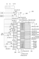
- control device 10 In the gas turbine combustor 100 according to some embodiments, the control device 10 includes the plurality of fuel flow control valves 310 and 320 and the fuel flow control section 11 that controls the plurality of fuel flow control valves 310 and 320 .
- the fuel flow rate control unit 11 includes a processor 12 that executes various types of arithmetic processing, and a memory 13 that non-temporarily or temporarily stores various data processed by the processor 12 .
- the processor 12 is implemented by a CPU, GPU, MPU, DSP, other various arithmetic devices, or a combination thereof.
- the memory 13 is implemented by ROM, RAM, flash memory, or a combination thereof.
- the air hole 250 extends in a direction that is inclined with respect to the central axis AXp of the air hole plate 25, there is a possibility that a region in which the flow velocity is relatively small locally occurs within the air hole plate 25 or at a position relatively close to the air hole plate 25.
- hydrogen which burns at a relatively high speed
- the flame may remain continuously in the above region if flashback occurs. If the flame continues to linger in this region, gas turbine combustor 100 may be damaged.
- damage to the gas turbine combustor 100 is suppressed as follows.
- hydrogen fuel is not supplied to the first fuel nozzle 21 during hydrogen fuel mono-firing. Since the hydrogen fuel is not supplied to the first air hole 251 having the inclined passage 256 during the hydrogen fuel mono-firing, it is possible to suppress the unintended continuation of the flame, thereby suppressing damage to the gas turbine combustor 100 .
- the second air hole group G2 may surround the first air hole group G1 when viewed along the central axis AXp of the air hole plate 25. Since the first air hole 251 has the inclined passage 256, the premixture of the fuel and the combustion air injected from the first air hole group G1 forms a circulating flow, which facilitates flame stabilization. Further, the ignition and flame holding of the premixed gas injected from the second air hole group G2 can be enhanced by the flame of the premixed gas injected from the first air hole group G1. As a result, it is possible to improve the flame stability of the gas turbine combustor 100 while suppressing unintended continuation of the flame.
- the first air hole group G1 may be formed in the central region Rc including the position where the central axis AXp of the air hole plate 25 passes through the air hole plate 25.
- a circulating flow is generated in the premixed gas in the region downstream of the central region Rc, facilitating flame stabilization.
- the ignition and flame holding of the premixed gas injected from the second air hole group G2 can be enhanced by the flame of the premixed gas injected from the first air hole group G1. Therefore, it is possible to improve the flame stability of the gas turbine combustor 100 while suppressing the unintended continuation of the flame.
- the first air hole groups G1 may be formed at a plurality of locations spaced apart along the circumferential direction of the air hole plate 25.
- a circulating flow is generated in the premixed gas in a plurality of downstream regions spaced apart along the circumferential direction of the air hole plate 25, thereby facilitating flame stabilization.
- the ignition and flame holding of the premixed gas injected from the second air hole group G2 can be enhanced by the flame of the premixed gas injected from the first air hole group G1. Therefore, it is possible to improve the flame stability of the gas turbine combustor 100 while suppressing the unintended continuation of the flame.
- the inner peripheral air holes 250i corresponding to the first row fuel nozzles 210 of the central burner 211, that is, the inner peripheral fuel nozzles 210i, may be the second air holes 252.
- natural gas fuel may be supplied to the plurality of first fuel nozzles 21 and the plurality of second fuel nozzles 22 so that the ratio of natural gas fuel in the premixed fuel of combustion air and natural gas fuel injected from the first air hole group G1 is greater than the ratio of natural gas fuel in the premixed fuel injected from the second air hole group G2.
- flame stability during natural gas fuel combustion is improved.
- the mixed fuel when hydrogen fuel and natural gas fuel are co-fired, the mixed fuel may be supplied to the plurality of first fuel nozzles 21 and the plurality of second fuel nozzles 22 when the hydrogen co-firing ratio, which is the ratio of the hydrogen fuel in the mixed fuel of hydrogen fuel and natural gas fuel, is equal to or less than the prescribed co-firing ratio, and the mixed fuel may be supplied only to the plurality of second fuel nozzles 22 when the hydrogen co-firing ratio exceeds the prescribed co-firing ratio.
- the hydrogen co-firing ratio which is the ratio of the hydrogen fuel in the mixed fuel of hydrogen fuel and natural gas fuel
- the mixed fuel of hydrogen fuel and natural gas fuel has a relatively high hydrogen co-firing ratio, unintended flames are likely to continue to linger. Therefore, as described above, when the hydrogen co-firing rate exceeds the specified co-firing rate, the mixed fuel is supplied only to the second fuel nozzle 22 and not to the first fuel nozzle 21. By doing so, it is possible to suppress unintended continuous flame flames. As a result, it is possible to suppress unintended continual lingering of the flame while ensuring the flame stability of the gas turbine combustor 100 .
- the hydrogen fuel may not be supplied to the first fuel nozzle 21 during co-firing of the hydrogen fuel and the natural gas fuel.
- only natural gas fuel may be supplied to the first fuel nozzle 21 in the fuel system 300 .
- unintended continuation of the flame can be further suppressed during co-firing of the hydrogen fuel and the natural gas fuel.
- natural gas fuel may be supplied to the first fuel nozzle 21 and the second fuel nozzle 22 during mono-firing of natural gas fuel. Since the first air hole 251 corresponding to the first fuel nozzle 21 has an inclined passage 256, the premixture of the fuel and combustion air injected from the first air hole 251 circulates and facilitates flame stabilization. Therefore, it is possible to improve the flame stability at the time of mono-firing of natural gas fuel.
- the hydrogen co-firing rate may be controlled as follows.
- FIG. 5A is a diagram for explaining control of the combustion injection ratios Q1, Q2, and Q3 based on the hydrogen co-firing ratio in the gas turbine combustor 100 according to the embodiment shown in FIGS. 2A and 3A.
- FIG. 5B is a diagram for explaining control of the combustion injection ratios Q1 and Q4 based on the hydrogen co-firing ratio in the gas turbine combustor 100 according to another embodiment shown in FIGS. 2B and 3B.
- FIG. 5A shows the ratios of the fuel injection ratios Q1, Q2, and Q3 to the hydrogen co-firing ratio (hereinafter also referred to as fuel ratios).
- the fuel injection ratio Q1 is the fuel injection ratio from the inner fuel nozzle 210i of the central burner 211
- the fuel injection ratio Q2 is the fuel injection ratio from the inner fuel nozzle 210i of the outer burner 212
- the fuel injection ratio Q3 is the fuel injection ratio from the outer fuel nozzle 210o of the central burner 211 and the outer burner 212.
- FIG. 5B shows the ratio (fuel ratio) of the fuel injection ratios Q1 and Q4 to the hydrogen co-firing ratio.
- the fuel injection ratio Q1 is the fuel injection ratio from the inner peripheral fuel nozzle 210i of the central burner 211
- the fuel injection ratio Q4 is the fuel injection ratio from the fuel nozzles 210 other than the inner peripheral fuel nozzle 210i of the central burner 211.
- the combustion injection ratio Q1 from the inner peripheral fuel nozzle 210i of the central burner 211 and the combustion injection from the inner peripheral fuel nozzle 210i of the outer burner 212 increase.
- the combustion injection ratio Q2 from the inner peripheral fuel nozzle 210i of the outer burner 212 is a constant value.
- the hydrogen co-firing ratio when the hydrogen co-firing ratio is in the range of the first co-firing ratio a1 (%) or more and the predetermined second co-firing ratio a2 (%) or less, as the hydrogen co-firing ratio increases, the combustion injection ratio Q1 from the inner peripheral fuel nozzle 210i of the central burner 211 gradually decreases, and the combustion injection from the peripheral fuel nozzle 210o of the central burner 211 and the outer burner 212.
- the ratio Q3 gradually increases.
- the combustion injection ratio Q1 from the inner peripheral fuel nozzle 210i of the central burner 211 becomes zero.
- the fuel injection ratio Q3 from the outer fuel nozzles 210o of the central burner 211 and the outer burner 212 is a constant value.
- the combustion injection ratio Q1 from the inner peripheral fuel nozzle 210i of the central burner 211 may be zero. That is, the combustion/injection ratio Q1 from the inner peripheral fuel nozzle 210i of the central burner 211 may change stepwise with the first mixed combustion ratio a1 (%) as a boundary.
- the fuel injection ratio Q3 from the outer peripheral fuel nozzle 210o of the central burner 211 and the outer burner 212 may be the same value as the value when the second co-firing ratio a2 (%) or more shown in FIG. 5A. That is, the fuel injection ratio Q3 from the outer fuel nozzles 210o of the central burner 211 and the outer burners 212 may change stepwise with the first mixed combustion ratio a1 (%) as a boundary.
- the rate of change of the combustion injection ratio Q1 changes with the first mixed combustion ratio a1 (%) as a boundary, but it may remain unchanged.
- the rate of change of the combustion/injection ratio Q3 changes with the first mixed combustion ratio a1 (%) as a boundary, but it may remain unchanged.
- the combustion injection ratio Q1 from the inner peripheral fuel nozzle 210i of the central burner 211 gradually decreases, and the fuel nozzles 21 other than the inner peripheral fuel nozzle 210i of the central burner 211 decrease.
- the combustion injection ratio Q4 from 0 gradually increases.
- the combustion injection ratio Q1 from the inner peripheral fuel nozzle 210i of the central burner 211 becomes zero, and all the fuel is injected from the fuel nozzles 210 other than the inner peripheral fuel nozzle 210i of the central burner 211.
- the combustion injection ratio Q1 from the inner peripheral fuel nozzle 210i of the central burner 211 may be zero. That is, the combustion/injection ratio Q1 from the inner peripheral fuel nozzle 210i of the central burner 211 may change stepwise with the first mixed combustion ratio a1 (%) as a boundary.
- the gas turbine combustor 100 according to another embodiment shown in FIGS. 2B and 3B when the hydrogen co-firing ratio exceeds the first co-firing ratio a1 (%), the combustion injection ratio Q1 from the inner peripheral fuel nozzle 210i of the central burner 211 may be zero. That is, the combustion/injection ratio Q1 from the inner peripheral fuel nozzle 210i of the central burner 211 may change stepwise with the first mixed combustion ratio a1 (%) as a boundary.
- the fuel injection ratio Q4 from the fuel nozzles 210 other than the inner peripheral fuel nozzle 210i of the central burner 211 may be the same value as the value when the second co-firing ratio a2 (%) or more shown in FIG. 5B. That is, the fuel injection ratio Q4 from the fuel nozzles 210 other than the inner peripheral fuel nozzle 210i of the central burner 211 may change stepwise with the first mixed combustion ratio a1 (%) as a boundary.
- the rate of change of the combustion injection ratio Q1 changes with the first mixed combustion ratio a1 (%) as a boundary, but it may remain unchanged.
- the rate of change of the combustion/injection ratio Q4 changes around the first mixed combustion ratio a1 (%), but it may remain unchanged.
- FIG. 6A is a graph showing changes in the fuel ratio and the hydrogen co-firing ratio from the start of operation of the gas turbine 1 including the gas turbine combustor 100 according to the embodiment shown in FIGS. 2A and 3A to transition to mono-firing of hydrogen fuel.
- FIG. 6B is a graph showing changes in fuel ratio and hydrogen co-firing ratio from the start of operation of the gas turbine 1 equipped with the gas turbine combustor 100 according to another embodiment shown in FIGS. As shown in FIGS.
- the operation of the gas turbine 1 may be started by mono-firing natural gas fuel (hydrogen co-firing ratio of 0%), and as time elapses, the hydrogen co-firing ratio may be gradually increased to transition to mono-firing of hydrogen fuel (hydrogen co-firing ratio of 100%).
- the processor 12 of the fuel flow control unit 11 calculates the opening degrees of the hydrogen flow control valve 311 and the natural gas flow control valve 312 so that fuel with the current hydrogen co-firing ratio determined by the operating conditions of the gas turbine 1, for example, is generated. Then, the processor 12 outputs a control signal for driving actuators (not shown) of the hydrogen flow control valve 311 and the natural gas flow control valve 312 so that the opening degrees of the hydrogen flow control valve 311 and the natural gas flow control valve 312 become the calculated opening degrees.
- actuators control the opening degrees of the hydrogen flow control valve 311 and the natural gas flow control valve 312 by receiving the control signal.
- fuel with a desired hydrogen co-firing ratio is produced by the mixing device 307 .
- the processor 12 of the fuel flow control unit 11 calculates the opening degrees of the first fuel flow control valve 321, the second fuel flow control valve 322, the third fuel flow control valve 323, and the fourth fuel flow control valve 324 so that the fuel ratio corresponds to the current hydrogen co-firing ratio determined by the operating conditions of the gas turbine 1, for example. Then, the processor 12 outputs control signals for driving the actuators (not shown) of the fuel flow control valves 321, 322, 323, 324 so that the openings of the fuel flow control valves 321, 322, 323, 324 become the calculated openings.
- each fuel flow control valve 321, 322, 323, 324 an actuator (not shown) adjusts the opening degree of each fuel flow control valve 321, 322, 323, 324 by receiving the control signal.
- fuel is injected from each fuel nozzle 210 so as to achieve a fuel ratio corresponding to the current hydrogen co-firing ratio.
- a control method for a gas turbine combustor 100 is a control method for a gas turbine combustor 100 that includes an air hole plate 25 in which a plurality of air holes 250 are formed, and a plurality of fuel nozzles 210 corresponding to each of the plurality of air holes 250, and that burns hydrogen fuel and other fuels other than hydrogen fuel.
- the plurality of air holes 250 includes a plurality of first air holes 251 having inclined passages 256 extending in a direction inclined with respect to the central axis AXp of the air hole plate 25 in a region including at least the outlet end 250b among the passages 255 between the inlet end 250a and the outlet end 250b, and a plurality of second air holes 252 extending parallel to the central axis AXp.
- the plurality of fuel nozzles 210 includes a plurality of first fuel nozzles 21 respectively corresponding to the plurality of first air holes 251 and a plurality of second fuel nozzles 22 respectively corresponding to the plurality of second air holes 252 . Hydrogen fuel is not supplied to the plurality of first fuel nozzles 21 during mono-fuel combustion of hydrogen fuel.
- the air hole plate 25 may have a first air hole group G1 in which a plurality of first air holes 251 are arranged adjacent to each other, and a second air hole group G2 in which a plurality of second air holes 252 are arranged adjacent to each other.
- the second air hole group G2 may surround the first air hole group G1 when viewed along the central axis AXp.
- the first air hole 251 since the first air hole 251 has the inclined passage 256, a circulating flow is generated in the premixture of the fuel and the combustion air injected from the first air hole group G1, which facilitates flame stabilization. Further, the ignition and flame holding of the premixed gas injected from the second air hole group G2 can be enhanced by the flame of the premixed gas injected from the first air hole group G1. As a result, it is possible to improve the flame stability of the gas turbine combustor 100 while suppressing unintended continuation of the flame.
- the first air hole group G1 may be formed in the central region Rc including the position where the center axis AXp passes through the air hole plate 25.
- a circulation flow is generated in the premixed gas in the region downstream of the central region Rc, making it easier to hold the flame. Further, the ignition and flame holding of the premixed gas injected from the second air hole group G2 can be enhanced by the flame of the premixed gas injected from the first air hole group G1. As a result, it is possible to improve the flame stability of the gas turbine combustor 100 while suppressing unintended continuation of the flame.
- the first air hole group G1 may be formed at a plurality of locations spaced apart along the circumferential direction of the air hole plate 25.
- a circulation flow is generated in the premixed gas in a plurality of downstream regions spaced apart along the circumferential direction of the air hole plate 25, thereby facilitating flame stabilization.
- the flame of the premixed gas injected from the first air hole group G1 can enhance the ignition and flame holding of the premixed gas injected from the second air hole group G2. As a result, it is possible to improve the flame stability of the gas turbine combustor 100 while suppressing unintended continuation of the flame.
- the other fuel when the other fuel is fired exclusively, the other fuel may be supplied to the plurality of first fuel nozzles 21 and the plurality of second fuel nozzles 22 so that the ratio of the other fuel in the premixed fuel of the combustion air and the other fuel injected from the first air hole group G1 is greater than the ratio of the other fuel in the premixed fuel injected from the second air hole group G2.
- the flame stability is improved when the other fuel is fired exclusively.
- the mixed fuel when the hydrogen fuel and the other fuel are co-fired, if the hydrogen co-firing rate, which is the ratio of the hydrogen fuel in the mixed fuel of the hydrogen fuel and the other fuel, is equal to or less than the specified co-firing rate, the mixed fuel may be supplied to the plurality of first fuel nozzles 21 and the plurality of second fuel nozzles 22, and if the hydrogen co-firing rate exceeds the specified co-firing rate, the mixed fuel may be supplied only to the plurality of second fuel nozzles 22. .
- hydrogen fuel may not be supplied to the plurality of first fuel nozzles 21 during mixed combustion of hydrogen fuel and other fuel.
- the other fuel may be supplied to the plurality of first fuel nozzles 21 and the plurality of second fuel nozzles 22 during mono-combustion of the other fuel.
- the control device 10 of the gas turbine combustor 100 includes an air hole plate 25 in which a plurality of air holes 250 are formed, and a plurality of fuel nozzles 210 corresponding to each of the plurality of air holes 250, and is a control device 10 for controlling combustion in the gas turbine combustor 100 that burns hydrogen fuel and other fuels other than hydrogen fuel.
- the plurality of air holes 250 includes a plurality of first air holes 251 having inclined passages 256 extending in a direction inclined with respect to the central axis AXp of the air hole plate 25 in a region including at least the outlet end 250b, and a plurality of second air holes extending parallel to the central axis.
- the plurality of fuel nozzles includes a plurality of first fuel nozzles 21 respectively corresponding to the plurality of first air holes 251 and a plurality of second fuel nozzles 22 respectively corresponding to the plurality of second air holes 252 .
- a control device 10 for a gas turbine combustor 100 includes fuel flow control valves 310 and 320 that adjust the flow rate of fuel supplied to a plurality of first fuel nozzles 21, and a fuel flow control unit 11 that controls the fuel flow control valves 310 and 320.
- the fuel flow rate control unit 11 controls the fuel flow rate control valves 310 and 320 so as not to supply the hydrogen fuel to the plurality of first fuel nozzles 21 during mono-fuel combustion of hydrogen fuel.
- Control device 11 Fuel flow controller 21 First fuel nozzle 22 Second fuel nozzle 25 Air hole plate 100 Gas turbine combustor 210 Fuel nozzle 250 Air hole 250a Inlet end 250b Outlet end 251 First air hole 252 Second air hole 255 Passage 256 Inclined passage 310 Fuel flow control valve 320 Fuel flow control valve G1 First air hole group G2 Second air hole group Rc central area
Landscapes
- Engineering & Computer Science (AREA)
- Chemical & Material Sciences (AREA)
- Combustion & Propulsion (AREA)
- Mechanical Engineering (AREA)
- General Engineering & Computer Science (AREA)
- Gas Burners (AREA)
Priority Applications (5)
| Application Number | Priority Date | Filing Date | Title |
|---|---|---|---|
| CN202380016535.5A CN118511036A (zh) | 2022-01-20 | 2023-01-13 | 燃气涡轮机燃烧器的控制方法及燃气涡轮机燃烧器的控制装置 |
| DE112023000354.8T DE112023000354T5 (de) | 2022-01-20 | 2023-01-13 | Steuerverfahren für gasturbinenbrennkammer und steuervorrichtung für gasturbinenbrennkammer |
| US18/727,215 US12404813B2 (en) | 2022-01-20 | 2023-01-13 | Control method for gas turbine combustor and control device for gas turbine combustor |
| KR1020247022076A KR102958848B1 (ko) | 2022-01-20 | 2023-01-13 | 가스 터빈 연소기의 제어 방법 및 가스 터빈 연소기의 제어 장치 |
| JP2023575222A JP7720928B2 (ja) | 2022-01-20 | 2023-01-13 | ガスタービン燃焼器の制御方法及びガスタービン燃焼器の制御装置 |
Applications Claiming Priority (2)
| Application Number | Priority Date | Filing Date | Title |
|---|---|---|---|
| JP2022006878 | 2022-01-20 | ||
| JP2022-006878 | 2022-01-20 |
Publications (1)
| Publication Number | Publication Date |
|---|---|
| WO2023140183A1 true WO2023140183A1 (ja) | 2023-07-27 |
Family
ID=87348801
Family Applications (1)
| Application Number | Title | Priority Date | Filing Date |
|---|---|---|---|
| PCT/JP2023/000738 Ceased WO2023140183A1 (ja) | 2022-01-20 | 2023-01-13 | ガスタービン燃焼器の制御方法及びガスタービン燃焼器の制御装置 |
Country Status (5)
| Country | Link |
|---|---|
| US (1) | US12404813B2 (https=) |
| JP (1) | JP7720928B2 (https=) |
| CN (1) | CN118511036A (https=) |
| DE (1) | DE112023000354T5 (https=) |
| WO (1) | WO2023140183A1 (https=) |
Cited By (3)
| Publication number | Priority date | Publication date | Assignee | Title |
|---|---|---|---|---|
| WO2024116963A1 (ja) * | 2022-12-01 | 2024-06-06 | 三菱重工業株式会社 | ガスタービンの運転方法 |
| WO2025033090A1 (ja) * | 2023-08-04 | 2025-02-13 | 三菱重工業株式会社 | ガスタービンの運転方法 |
| WO2025192443A1 (ja) * | 2024-03-15 | 2025-09-18 | 三菱重工業株式会社 | バーナ、燃焼器及びガスタービン |
Citations (7)
| Publication number | Priority date | Publication date | Assignee | Title |
|---|---|---|---|---|
| JP2008292139A (ja) * | 2007-04-26 | 2008-12-04 | Hitachi Ltd | 燃焼器及び燃焼器の燃料供給方法 |
| JP2009210200A (ja) * | 2008-03-05 | 2009-09-17 | Hitachi Ltd | 燃焼器及び燃焼器の燃料供給方法 |
| JP2010133339A (ja) * | 2008-12-05 | 2010-06-17 | Hitachi Ltd | ガスタービンの運転方法及びガスタービン燃焼器 |
| JP2014105601A (ja) * | 2012-11-26 | 2014-06-09 | Hitachi Ltd | ガスタービン燃焼器及びその運転方法 |
| JP2016038108A (ja) * | 2014-08-05 | 2016-03-22 | 三菱日立パワーシステムズ株式会社 | ガスタービン燃焼器 |
| JP2018071354A (ja) * | 2016-10-24 | 2018-05-10 | 三菱日立パワーシステムズ株式会社 | ガスタービン燃焼器及びその運転方法 |
| JP2021055644A (ja) * | 2019-10-01 | 2021-04-08 | 三菱パワー株式会社 | ガスタービン燃焼器及びその運転方法 |
Family Cites Families (18)
| Publication number | Priority date | Publication date | Assignee | Title |
|---|---|---|---|---|
| US6928823B2 (en) * | 2001-08-29 | 2005-08-16 | Hitachi, Ltd. | Gas turbine combustor and operating method thereof |
| JP4728176B2 (ja) * | 2005-06-24 | 2011-07-20 | 株式会社日立製作所 | バーナ、ガスタービン燃焼器及びバーナの冷却方法 |
| JP4922878B2 (ja) | 2007-09-19 | 2012-04-25 | 株式会社日立製作所 | ガスタービン燃焼器 |
| JP4872992B2 (ja) | 2008-09-12 | 2012-02-08 | 株式会社日立製作所 | 燃焼器,燃焼器の燃料供給方法及び燃焼器の改造方法 |
| JP5103454B2 (ja) * | 2009-09-30 | 2012-12-19 | 株式会社日立製作所 | 燃焼器 |
| JP5470662B2 (ja) * | 2011-01-27 | 2014-04-16 | 株式会社日立製作所 | ガスタービン燃焼器 |
| JP5908379B2 (ja) * | 2012-09-24 | 2016-04-26 | 三菱日立パワーシステムズ株式会社 | ガスタービン燃焼器 |
| JP6158504B2 (ja) | 2012-12-20 | 2017-07-05 | 三菱日立パワーシステムズ株式会社 | バーナ |
| JP6190670B2 (ja) * | 2013-08-30 | 2017-08-30 | 三菱日立パワーシステムズ株式会社 | ガスタービン燃焼システム |
| US10018359B2 (en) | 2013-11-05 | 2018-07-10 | Mitsubishi Hitachi Power Systems, Ltd. | Gas turbine combustor |
| JP6484546B2 (ja) * | 2015-11-13 | 2019-03-13 | 三菱日立パワーシステムズ株式会社 | ガスタービン燃焼器 |
| JP2017186950A (ja) * | 2016-04-05 | 2017-10-12 | 三菱日立パワーシステムズ株式会社 | ガスタービン燃焼器 |
| JP6800787B2 (ja) | 2017-03-15 | 2020-12-16 | 三菱パワー株式会社 | ガスタービン燃焼器及びその制御方法 |
| JP7044669B2 (ja) * | 2018-09-05 | 2022-03-30 | 三菱重工業株式会社 | ガスタービン燃焼器 |
| JP7130545B2 (ja) * | 2018-12-20 | 2022-09-05 | 三菱重工業株式会社 | ガスタービン燃焼器、ガスタービン及びガスタービン燃焼器の製造方法 |
| JP2021055971A (ja) * | 2019-10-01 | 2021-04-08 | 三菱パワー株式会社 | ガスタービン燃焼器 |
| JP7270517B2 (ja) * | 2019-10-01 | 2023-05-10 | 三菱重工業株式会社 | ガスタービン燃焼器 |
| JP7383573B2 (ja) | 2020-06-25 | 2023-11-20 | 株式会社パイロットコーポレーション | 熱変色性筆記具用水性インキ組成物、およびそれを用いた筆記具 |
-
2023
- 2023-01-13 DE DE112023000354.8T patent/DE112023000354T5/de active Pending
- 2023-01-13 CN CN202380016535.5A patent/CN118511036A/zh active Pending
- 2023-01-13 WO PCT/JP2023/000738 patent/WO2023140183A1/ja not_active Ceased
- 2023-01-13 US US18/727,215 patent/US12404813B2/en active Active
- 2023-01-13 JP JP2023575222A patent/JP7720928B2/ja active Active
Patent Citations (7)
| Publication number | Priority date | Publication date | Assignee | Title |
|---|---|---|---|---|
| JP2008292139A (ja) * | 2007-04-26 | 2008-12-04 | Hitachi Ltd | 燃焼器及び燃焼器の燃料供給方法 |
| JP2009210200A (ja) * | 2008-03-05 | 2009-09-17 | Hitachi Ltd | 燃焼器及び燃焼器の燃料供給方法 |
| JP2010133339A (ja) * | 2008-12-05 | 2010-06-17 | Hitachi Ltd | ガスタービンの運転方法及びガスタービン燃焼器 |
| JP2014105601A (ja) * | 2012-11-26 | 2014-06-09 | Hitachi Ltd | ガスタービン燃焼器及びその運転方法 |
| JP2016038108A (ja) * | 2014-08-05 | 2016-03-22 | 三菱日立パワーシステムズ株式会社 | ガスタービン燃焼器 |
| JP2018071354A (ja) * | 2016-10-24 | 2018-05-10 | 三菱日立パワーシステムズ株式会社 | ガスタービン燃焼器及びその運転方法 |
| JP2021055644A (ja) * | 2019-10-01 | 2021-04-08 | 三菱パワー株式会社 | ガスタービン燃焼器及びその運転方法 |
Cited By (3)
| Publication number | Priority date | Publication date | Assignee | Title |
|---|---|---|---|---|
| WO2024116963A1 (ja) * | 2022-12-01 | 2024-06-06 | 三菱重工業株式会社 | ガスタービンの運転方法 |
| WO2025033090A1 (ja) * | 2023-08-04 | 2025-02-13 | 三菱重工業株式会社 | ガスタービンの運転方法 |
| WO2025192443A1 (ja) * | 2024-03-15 | 2025-09-18 | 三菱重工業株式会社 | バーナ、燃焼器及びガスタービン |
Also Published As
| Publication number | Publication date |
|---|---|
| JP7720928B2 (ja) | 2025-08-08 |
| US20250092834A1 (en) | 2025-03-20 |
| CN118511036A (zh) | 2024-08-16 |
| US12404813B2 (en) | 2025-09-02 |
| DE112023000354T5 (de) | 2024-08-22 |
| KR20240121266A (ko) | 2024-08-08 |
| JPWO2023140183A1 (https=) | 2023-07-27 |
Similar Documents
| Publication | Publication Date | Title |
|---|---|---|
| US12404813B2 (en) | Control method for gas turbine combustor and control device for gas turbine combustor | |
| US9074772B2 (en) | Combustor and operating method thereof | |
| JP4177812B2 (ja) | タービンエンジンの燃料ノズル | |
| US10941940B2 (en) | Burner for a gas turbine and method for operating the burner | |
| JP5400936B2 (ja) | ガスタービンエンジン内で燃料を燃焼させるための方法及び装置 | |
| US11015809B2 (en) | Pilot nozzle in gas turbine combustor | |
| EP1426689B1 (en) | Gas turbine combustor having staged burners with dissimilar mixing passage geometries | |
| US20170074519A1 (en) | Gas Turbine Combustor | |
| JP5458121B2 (ja) | ガスタービン燃焼器およびガスタービン燃焼器の運転方法 | |
| CN101949540A (zh) | 对涡轮燃烧器燃料喷嘴中火焰稳定和回火的主动控制 | |
| JPH0828874A (ja) | ガスタービン燃焼器及びガスタービン | |
| JP2015534632A (ja) | 改良された操作性のための半径方向に段付けされた予混合されるパイロットを備える燃焼器 | |
| EP2943725A1 (en) | Lean-rich axial stage combustion in a can-annular gas turbine engine | |
| US6880339B2 (en) | Combination of a premixing chamber and a combustion chamber, with low emission of pollutants, for gas turbines running on liquid and/or gas fuel | |
| US12474053B2 (en) | Fuel injector and fuel nozzle for a gas turbine, and gas turbine engine including the nozzle | |
| EP4278133A1 (en) | Combustor for a gas turbine | |
| KR20140082659A (ko) | 가스 터빈 엔진에서 사용되는 예비혼합형 접선방향 연료-공기 노즐을 가진 캔-애뉼러형 연소실 | |
| JP2003207130A (ja) | 汚染物質低排出のガスタービンの予混合室付き単一燃焼室用の主液体燃料噴射装置 | |
| US7836677B2 (en) | At least one combustion apparatus and duct structure for a gas turbine engine | |
| US11493206B2 (en) | Gas turbine combustor having main fuel valves independently adjustable | |
| KR102958848B1 (ko) | 가스 터빈 연소기의 제어 방법 및 가스 터빈 연소기의 제어 장치 | |
| JP6182395B2 (ja) | ガスタービン燃焼器及びその制御方法 | |
| JP6740375B2 (ja) | 排気を減らすための選択的燃焼器制御の方法 | |
| US10371048B2 (en) | Combustor and gas turbine | |
| CN117321340B (en) | Fuel injector and fuel nozzle for a gas turbine and gas turbine engine comprising such a nozzle |
Legal Events
| Date | Code | Title | Description |
|---|---|---|---|
| 121 | Ep: the epo has been informed by wipo that ep was designated in this application |
Ref document number: 23743177 Country of ref document: EP Kind code of ref document: A1 |
|
| WWE | Wipo information: entry into national phase |
Ref document number: 2023575222 Country of ref document: JP |
|
| ENP | Entry into the national phase |
Ref document number: 20247022076 Country of ref document: KR Kind code of ref document: A |
|
| WWE | Wipo information: entry into national phase |
Ref document number: 112023000354 Country of ref document: DE |
|
| WWE | Wipo information: entry into national phase |
Ref document number: 18727215 Country of ref document: US Ref document number: 202380016535.5 Country of ref document: CN |
|
| 122 | Ep: pct application non-entry in european phase |
Ref document number: 23743177 Country of ref document: EP Kind code of ref document: A1 |
|
| WWP | Wipo information: published in national office |
Ref document number: 18727215 Country of ref document: US |
|
| WWG | Wipo information: grant in national office |
Ref document number: 18727215 Country of ref document: US |