WO2023140038A1 - 測定装置 - Google Patents
測定装置 Download PDFInfo
- Publication number
- WO2023140038A1 WO2023140038A1 PCT/JP2022/047301 JP2022047301W WO2023140038A1 WO 2023140038 A1 WO2023140038 A1 WO 2023140038A1 JP 2022047301 W JP2022047301 W JP 2022047301W WO 2023140038 A1 WO2023140038 A1 WO 2023140038A1
- Authority
- WO
- WIPO (PCT)
- Prior art keywords
- sensor
- human body
- measuring device
- signal
- blood vessel
- Prior art date
- Legal status (The legal status is an assumption and is not a legal conclusion. Google has not performed a legal analysis and makes no representation as to the accuracy of the status listed.)
- Ceased
Links
Images




Classifications
-
- A—HUMAN NECESSITIES
- A61—MEDICAL OR VETERINARY SCIENCE; HYGIENE
- A61B—DIAGNOSIS; SURGERY; IDENTIFICATION
- A61B5/00—Measuring for diagnostic purposes; Identification of persons
- A61B5/02—Detecting, measuring or recording for evaluating the cardiovascular system, e.g. pulse, heart rate, blood pressure or blood flow
Definitions
- the present invention relates to a measuring device that measures parameters related to blood vessel stiffness.
- Patent Document 1 the intravascular ultrasound technology described in Patent Document 1 is known as an invention related to a measuring device for measuring parameters related to blood vessel stiffness.
- This technique measures the stiffness of the blood vessel by propagating ultrasonic waves inside the blood vessel.
- an object of the present invention is to provide a measuring device that can measure blood vessel stiffness-related parameters without damaging the human body and that can accurately measure blood vessel stiffness-related parameters.
- a measuring device includes: a first sensor that contacts the surface of the human body and outputs a first signal by detecting a pulse wave of the first part of the human body; a first fixing member that fixes the first sensor to the first portion; a second sensor that contacts the surface of the human body and outputs a second signal by detecting a pulse wave of a second portion of the human body; a second fixing member that fixes the second sensor to the second portion; an arithmetic circuit for generating blood vessel stiffness-related data indicating a parameter related to blood vessel stiffness of the human body based on the first signal and the second signal; and the first portion is a joint; The first fixing member brings the first sensor into close contact with the first portion.
- the measuring device it is possible to measure the parameters related to blood vessel stiffness without damaging the human body, and to measure the parameters related to blood vessel stiffness with high accuracy.
- FIG. 1 is a block diagram of the measuring device 10.
- FIG. 2 is a top view and cross-sectional view of the first sensor 12a.
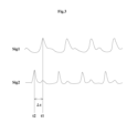
- FIG. 3 is a diagram showing waveforms of the first signal Sig1 and the second signal Sig2.
- FIG. 4 is a graph showing the relationship between the square of the pulse wave velocity V2 and the blood vessel stiffness G.
- FIG. 5 is a flowchart executed by the arithmetic circuit 18.
- FIG. FIG. 6 is a block diagram of the measuring device 10a.
- FIG. 1 is a block diagram of the measuring device 10.
- FIG. 2 is a top view and cross-sectional view of the first sensor 12a.
- FIG. 3 is a diagram showing waveforms of the first signal Sig1 and the second signal Sig2.
- FIG. 4 is a graph showing the relationship between pulse wave velocity V and blood vessel stiffness G.
- the measuring device 10 is a device that calculates parameters related to blood vessel stiffness of the human body.
- the measuring device 10 is, for example, a device that measures arteriosclerosis of a human body.
- the measuring device 10 includes a first sensor 12a, a second sensor 12b, a first fixing member 14a, a second fixing member 14b, a connecting member 16, an arithmetic circuit 18, and a display device 20, as shown in FIG.
- the first sensor 12a outputs the first signal Sig1 by detecting the pulse wave of the first part of the human body.
- the first part is the joint.
- the first portion is the wrist.
- the first sensor 12a detects expansion and contraction of the surface of the human body caused by pulse waves and generates an electrical signal having a voltage value corresponding to the expansion and contraction.
- the structure of the first sensor 12a will be described below.
- the first sensor 12a includes a piezoelectric film 24, an upper electrode 25a, a lower electrode 25b, a substrate 26, an adhesive layer 28 and an adhesive layer 30.
- the piezoelectric film 24 has a sheet shape.
- piezoelectric film 24 has an upper major surface and a lower major surface.
- the length of the piezoelectric film 24 in the left-right direction is longer than the length of the piezoelectric film 24 in the front-rear direction.
- the piezoelectric film 24 has a rectangular shape with long sides extending in the horizontal direction when viewed in the vertical direction.
- the piezoelectric film 24 generates an electric charge according to the amount of deformation of the piezoelectric film 24 .
- the piezoelectric film 24 is a PLA film. The piezoelectric film 24 will be described in more detail below.
- the piezoelectric film 24 has the property that the polarity of the charge generated when the piezoelectric film 24 is stretched in the left-right direction is opposite to the polarity of the charge generated when the piezoelectric film 24 is stretched in the front-rear direction.
- piezoelectric film 24 is a film formed from a chiral polymer.
- a chiral polymer is, for example, polylactic acid (PLA), particularly L-type polylactic acid (PLLA).
- a PLLA composed of a chiral polymer has a helical structure in its main chain. PLLA is uniaxially stretched and has piezoelectricity in which the molecules are oriented.
- the piezoelectric film 24 has a piezoelectric constant of d14.
- the uniaxial stretching direction (orientation direction) of the piezoelectric film 24 forms an angle of 45 degrees with respect to each of the front-back direction and the left-right direction.
- This 45 degrees includes angles including, for example, about 45 degrees ⁇ 10 degrees.
- the piezoelectric film 24 generates an electric charge when the piezoelectric film 24 is stretched in the front-back direction and the left-right direction or compressed in the front-back direction and the left-right direction.
- the piezoelectric film 24 generates a positive charge, for example, when stretched in the left-right direction.
- the piezoelectric film 24, for example, generates a negative charge when compressed in the left-right direction.
- the piezoelectric film 24, for example, generates a negative charge when stretched in the front-rear direction.
- the piezoelectric film 24 for example, generates a positive charge when compressed in the front-to-back direction.
- the magnitude of the charge depends on the amount of deformation of the piezoelectric film 24 due to stretching or compression. More precisely, the magnitude of the charge is proportional to the derivative of the deformation of the piezoelectric film 24 due to extension or compression.
- the upper electrode 25a is a signal electrode.
- a first signal Sig1 is output from the upper electrode 25a.
- the upper electrode 25 a is provided on the upper main surface of the piezoelectric film 24 .
- the lower electrode 25b is a ground electrode.
- the lower electrode 25b is connected to ground.
- the lower electrode 25 b is provided on the lower main surface of the piezoelectric film 24 .
- the material of the upper electrode 25a and the material of the lower electrode 25b are, for example, a conductive polymer such as PEDOT.
- the base material 26 is provided on the upper electrode 25a.
- the substrate 26 deforms together with the piezoelectric film 24 by holding the piezoelectric film 24, the upper electrode 25a and the lower electrode 25b.
- the base material 26 has a sheet shape.
- the substrate 26 has an upper major surface and a lower major surface.
- the length of the base material 26 in the left-right direction is longer than the length of the base material 26 in the front-rear direction.
- the base material 26 has a rectangular shape with long sides extending in the horizontal direction when viewed in the vertical direction.
- the long side of the base material 26 is longer than the long side of the piezoelectric film 24, the long side of the upper electrode 25a, and the long side of the lower electrode 25b.
- the short side of the substrate 26 is longer than the short side of the piezoelectric film 24, the short side of the upper electrode 25a, and the short side of the lower electrode 25b.
- the piezoelectric film 24, the upper electrode 25a, and the lower electrode 25b are arranged within a region surrounded by the outer edge of the substrate 26 when viewed in the vertical direction.
- the material of the base material 26 is, for example, polyurethane or PET. You may form with a flexible substrate and a printed wiring board.
- the adhesive layer 28 fixes the piezoelectric film 24 , the upper electrode 25 a and the lower electrode 25 b to the base material 26 . More specifically, the adhesive layer 28 is provided on the lower major surface of the substrate 26 . Adhesive layer 28 covers a portion of the lower major surface of substrate 26 . Further, the adhesive layer 28 covers the entire upper main surface of the upper electrode 25a. The outer edge of the adhesive layer 28 is surrounded by the outer edge of the base material 26 when viewed in the vertical direction. The adhesive layer 28 bonds the upper electrode 25a and the base material 26 together. As a result, deformation of substrate 26 is transmitted to piezoelectric film 24 .
- the material of the adhesive layer 28 is, for example, double-sided tape, thermosetting adhesive, or thermoplastic adhesive.
- the adhesive layer 30 is provided on the upper main surface of the base material 26 .
- the adhesive layer 30 secures the substrate 26 to the first portion. Accordingly, when the first portion is deformed, the substrate 26 is deformed and the piezoelectric film 24 is deformed.
- the first fixing member 14a contacts the surface of the human body and fixes the first sensor 12a to the first portion.
- the first fixing member 14a brings the first sensor 12a into close contact with the first portion. That the first sensor 12a is in close contact with the first portion means that there is no gap between the first sensor 12a and the first portion.
- the first fixing member 14a is, for example, a resin film having an adhesive layer.
- the first sensor 12a is attached to the first fixing member 14a so that the lower electrode 15b is in contact with the first fixing member 14a. Thereby, the first sensor 12a can be in close contact with the first portion.
- the second sensor 12b outputs the second signal Sig2 by contacting the surface of the human body and detecting the pulse wave of the second part of the human body.
- the second part is the joint.
- the second part is, for example, the elbow. Since the structure of the second sensor 12b is the same as that of the first sensor 12a, the description thereof is omitted.
- the second fixing member 14b fixes the second sensor 12b to the second portion. Since the structure of the second fixing member 14b is the same as the structure of the first fixing member 14a, the description thereof is omitted.
- the first sensor 12a and the second sensor 12b are in close contact with the first portion and the second portion
- first sensor 12a and the second sensor 12b do not have to be in direct contact with the first portion and the second portion. It is sufficient that the first sensor 12a and the second sensor 12b can detect expansion and contraction of the first portion and the second portion caused by the pulse wave. Therefore, an intervening material such as a silicone resin or a thin resin film may exist between the first sensor 12a and the first portion and/or between the second sensor 12b and the second portion.
- the connecting member 16 connects the first fixing member 14a and the second fixing member 14b.
- the connecting member 16 plays a role of keeping a constant distance L between the first sensor 12a and the second sensor 12b.
- the arithmetic circuit 18 Based on the first signal Sig1 and the second signal Sig2, the arithmetic circuit 18 generates blood vessel stiffness related data D indicating parameters related to the blood vessel stiffness of the human body. Generation of the blood vessel stiffness related data D will be described below.
- the pulse wave generation time included in the first signal Sig1 is called time t1.
- the pulse wave generation time included in the second signal Sig2 is referred to as time t2.
- the distance between the second sensor 12b and the heart is shorter than the distance between the first sensor 12a and the heart. Therefore, time t2 is before time t1.
- the difference between time t2 and time t1 is called difference ⁇ t.
- the arithmetic circuit 18 divides the distance L by the difference ⁇ t to calculate the pulse wave propagation velocity V, which is the velocity at which the pulse wave propagates. Note that the distance L is stored in a storage device (not shown).
- the blood vessel stiffness G is a parameter that indicates the stiffness of blood vessels in the human body. As the vessel stiffness G increases, the vessel becomes stiffer. That is, the blood vessel stiffness G indicates the degree of arteriosclerosis of the human body.
- the square of the pulse wave velocity V (V 2 ) and the blood vessel stiffness G have a proportional relationship, as shown in FIG. That is, when the square of the pulse wave velocity V increases, the blood vessel stiffness G increases. Therefore, if the pulse wave velocity V can be known, the blood vessel stiffness G can be known. Therefore, data corresponding to the graph in FIG.
- the arithmetic circuit 18 calculates the blood vessel stiffness G based on the pulse wave propagation velocity V using the data corresponding to the graph of FIG. Therefore, in this embodiment, the parameter related to the vascular stiffness of the human body is the vascular stiffness G.
- the arithmetic circuit 18 generates the blood vessel stiffness related data D such that the parameter changes when the difference ⁇ t between the pulse wave occurrence time t1 included in the first signal Sig1 and the pulse wave occurrence time t2 included in the second signal Sig2 changes.
- the arithmetic circuit 18 generates the blood vessel stiffness related data D such that the blood vessel stiffness G increases as the difference ⁇ t increases.
- the arithmetic circuit 18 as described above is, for example, a CPU (Central Processing Unit).
- the display device 20 displays parameters indicated by the blood vessel stiffness related data D generated by the arithmetic circuit 18 .
- the display device 20 displays the blood vessel stiffness G.
- FIG. The display device 20 is, for example, a liquid crystal display device or an organic EL display device.
- FIG. 5 is a flowchart executed by the arithmetic circuit 18. As shown in FIG. The arithmetic circuit 18 executes the flowchart of FIG. 5 by executing a program stored in a storage device (not shown).
- the arithmetic circuit 18 acquires the first signal Sig1 and the second signal Sig2 (step S1). Next, as shown in FIG. 2, the arithmetic circuit 18 detects a pulse wave from the first signal Sig1 and the second signal Sig2 (step S2). More specifically, the arithmetic circuit 18 identifies the pulse wave generation time t1 included in the first signal Sig1 and the pulse wave generation time t2 included in the second signal Sig2.
- the arithmetic circuit 18 acquires the difference ⁇ t between the generation time t1 and the generation time t2 of the detected pulse wave (step S3). Arithmetic circuit 18 then calculates pulse wave velocity V by dividing distance L stored in the storage device by difference ⁇ t (step S4). Finally, the arithmetic circuit 18 uses the data corresponding to the graph of FIG. 4 to calculate the blood vessel stiffness G based on the pulse wave velocity V (step S5). After that, the display device 20 displays the blood vessel stiffness G.
- the measuring device 10 parameters related to blood vessel stiffness can be measured without injuring the human body. More specifically, the first sensor 12a outputs the first signal Sig1 by contacting the surface of the human body and detecting the pulse wave of the first part of the human body. The second sensor 12b outputs a second signal Sig2 by contacting the surface of the human body and detecting the pulse wave of the second part of the human body. Based on the first signal Sig1 and the second signal Sig2, the arithmetic circuit 18 generates blood vessel stiffness-related data D representing parameters related to the blood vessel stiffness of the human body. Thus, the measuring device 10 can measure parameters related to blood vessel stiffness without damaging the human body.
- the measuring device 10 parameters related to blood vessel stiffness can be measured with high accuracy. More specifically, as a result of research, the inventors of the present application came to the conclusion that the pulse wave measurement position should be a joint. Furthermore, as a result of research, the inventors of the present application came to the conclusion that the pulse wave should be measured at the wrist. However, the wrist has complicated unevenness and is deformed. Therefore, the first fixing member 14a brings the first sensor 12a into close contact with the first portion, which is a joint. As a result, the first sensor 12a can accurately detect the pulse wave. As a result, the measuring device 10 can accurately measure parameters related to blood vessel stiffness.
- the connecting member 16 connects the first fixing member 14a and the second fixing member 14b. Thereby, the distance L between the first sensor 12a and the second sensor 12b is kept constant. As a result, it is unnecessary to measure and input the distance L between the first sensor 12a and the second sensor 12b.
- FIG. 6 is a block diagram of the measuring device 10a.
- the measuring device 10a differs from the measuring device 10 in that it does not include the connecting member 16 and further includes an input device 21. Therefore, the distance L between the first sensor 12a and the second sensor 12b is not constant. Therefore, the user measures the distance L. Furthermore, the user inputs the distance L using the input device 21 . Thereby, the arithmetic circuit 18 acquires the distance data DL indicating the distance L between the first portion and the second portion. Arithmetic circuit 18 generates blood vessel stiffness-related data D based on first signal Sig1, second signal Sig2, and distance data DL. Other structures of measuring device 10a are the same as those of measuring device 10, and description thereof will be omitted.
- the measuring apparatus according to the present invention is not limited to the measuring apparatuses 10 and 10a, and can be modified within the scope of the gist thereof. Also, the structures of the measurement devices 10 and 10a may be combined.
- the first sensor 12a and the second sensor 12b may be ultrasonic sensors or photoplethysmography sensors. Also, the first sensor 12a and the second sensor 12b may be different types of sensors.
- the second part does not have to be a joint.
- the second fixing member 14b does not need to bring the second sensor 12b into close contact with the second portion.
- the second fixing member 14b may be a band wrapped around a part of the human body.
- the parameter may be the pulse wave velocity V, which is the velocity at which the pulse wave propagates.
- the display device 20 displays the pulse wave velocity V.
- the parameters may be both the blood vessel stiffness G and the pulse wave velocity V.
- the parameter may be a value indicating the degree of arteriosclerosis of the human body.
- the arithmetic circuit 18 may use the difference ⁇ t to calculate the blood vessel stiffness G without calculating the pulse wave propagation velocity V.
- a storage device (not shown) stores a table showing the relationship between the difference ⁇ t and the blood vessel stiffness G.
- the first portion may be a joint other than the wrist.
- measuring devices 10 and 10a may further include a printing device for printing parameters.
- the arithmetic circuit 18 may generate the blood vessel stiffness-related data D indicating the parameters related to the blood vessel stiffness of the human body based on the first signal Sig1 and the second signal Sig2 when the human body is stimulated and the first signal Sig1 and the second signal Sig2 when the human body is not stimulated. Since the measuring devices 10 and 10a can measure the blood vessel stiffness-related data D in real time, it is possible to evaluate physical pain and mental stress felt by a person in real time using quantitative data. Heart rate variability analysis, which is currently used as a stress index, is known to take a certain amount of time to measure, and cannot be used to evaluate stimuli in a short period of time.
Landscapes
- Health & Medical Sciences (AREA)
- Life Sciences & Earth Sciences (AREA)
- Biomedical Technology (AREA)
- Heart & Thoracic Surgery (AREA)
- Physiology (AREA)
- Biophysics (AREA)
- Pathology (AREA)
- Engineering & Computer Science (AREA)
- Cardiology (AREA)
- Physics & Mathematics (AREA)
- Medical Informatics (AREA)
- Molecular Biology (AREA)
- Surgery (AREA)
- Animal Behavior & Ethology (AREA)
- General Health & Medical Sciences (AREA)
- Public Health (AREA)
- Veterinary Medicine (AREA)
- Measuring Pulse, Heart Rate, Blood Pressure Or Blood Flow (AREA)
Priority Applications (1)
| Application Number | Priority Date | Filing Date | Title |
|---|---|---|---|
| JP2023575153A JP7580095B2 (ja) | 2022-01-21 | 2022-12-22 | 測定装置 |
Applications Claiming Priority (2)
| Application Number | Priority Date | Filing Date | Title |
|---|---|---|---|
| JP2022-008023 | 2022-01-21 | ||
| JP2022008023 | 2022-01-21 |
Publications (1)
| Publication Number | Publication Date |
|---|---|
| WO2023140038A1 true WO2023140038A1 (ja) | 2023-07-27 |
Family
ID=87348208
Family Applications (1)
| Application Number | Title | Priority Date | Filing Date |
|---|---|---|---|
| PCT/JP2022/047301 Ceased WO2023140038A1 (ja) | 2022-01-21 | 2022-12-22 | 測定装置 |
Country Status (2)
| Country | Link |
|---|---|
| JP (1) | JP7580095B2 (https=) |
| WO (1) | WO2023140038A1 (https=) |
Citations (7)
| Publication number | Priority date | Publication date | Assignee | Title |
|---|---|---|---|---|
| JP2005226902A (ja) * | 2004-02-12 | 2005-08-25 | Daikin Ind Ltd | 環境温度の制御方法、温熱ストレスの報知方法、温熱ストレスの測定方法、環境温度制御装置、温熱ストレス報知装置及び温熱ストレス測定装置 |
| US20080039731A1 (en) * | 2005-08-22 | 2008-02-14 | Massachusetts Institute Of Technology | Wearable Pulse Wave Velocity Blood Pressure Sensor and Methods of Calibration Thereof |
| WO2014208289A1 (ja) * | 2013-06-28 | 2014-12-31 | 株式会社村田製作所 | 生体状態推定装置 |
| US20190059752A1 (en) * | 2017-08-28 | 2019-02-28 | Planexta, Inc. | Method and apparatus for cuff less blood pressure monitoring based on simultaneously measured ECG and PPG signals designed in wristband form for continuous wearing |
| JP2019516416A (ja) * | 2016-05-03 | 2019-06-20 | サムスン エレクトロニクス カンパニー リミテッド | 心血管特性抽出装置及び方法 |
| CN209770350U (zh) * | 2018-12-10 | 2019-12-13 | 重庆医科大学 | 一种心血管健康评估装置 |
| JP2022000065A (ja) * | 2020-06-19 | 2022-01-04 | 国立大学法人広島大学 | 血管剛性推定方法、血管剛性推定装置及びプログラム |
-
2022
- 2022-12-22 JP JP2023575153A patent/JP7580095B2/ja active Active
- 2022-12-22 WO PCT/JP2022/047301 patent/WO2023140038A1/ja not_active Ceased
Patent Citations (7)
| Publication number | Priority date | Publication date | Assignee | Title |
|---|---|---|---|---|
| JP2005226902A (ja) * | 2004-02-12 | 2005-08-25 | Daikin Ind Ltd | 環境温度の制御方法、温熱ストレスの報知方法、温熱ストレスの測定方法、環境温度制御装置、温熱ストレス報知装置及び温熱ストレス測定装置 |
| US20080039731A1 (en) * | 2005-08-22 | 2008-02-14 | Massachusetts Institute Of Technology | Wearable Pulse Wave Velocity Blood Pressure Sensor and Methods of Calibration Thereof |
| WO2014208289A1 (ja) * | 2013-06-28 | 2014-12-31 | 株式会社村田製作所 | 生体状態推定装置 |
| JP2019516416A (ja) * | 2016-05-03 | 2019-06-20 | サムスン エレクトロニクス カンパニー リミテッド | 心血管特性抽出装置及び方法 |
| US20190059752A1 (en) * | 2017-08-28 | 2019-02-28 | Planexta, Inc. | Method and apparatus for cuff less blood pressure monitoring based on simultaneously measured ECG and PPG signals designed in wristband form for continuous wearing |
| CN209770350U (zh) * | 2018-12-10 | 2019-12-13 | 重庆医科大学 | 一种心血管健康评估装置 |
| JP2022000065A (ja) * | 2020-06-19 | 2022-01-04 | 国立大学法人広島大学 | 血管剛性推定方法、血管剛性推定装置及びプログラム |
Also Published As
| Publication number | Publication date |
|---|---|
| JPWO2023140038A1 (https=) | 2023-07-27 |
| JP7580095B2 (ja) | 2024-11-11 |
Similar Documents
| Publication | Publication Date | Title |
|---|---|---|
| RU2750352C2 (ru) | Сенсорное устройство и способ измерения физиологического параметра | |
| Laurila et al. | Self-powered, high sensitivity printed e-tattoo sensor for unobtrusive arterial pulse wave monitoring | |
| JP3575025B2 (ja) | 脈波検出装置および拍動検出装置 | |
| US8075489B2 (en) | Ultrasound diagnostic apparatus | |
| JP6910290B2 (ja) | 振動波形センサ及び波形解析装置 | |
| Digiglio et al. | Microflotronic arterial tonometry for continuous wearable non-invasive hemodynamic monitoring | |
| JPH095014A (ja) | 曲げセンサ | |
| JP2004208711A (ja) | 圧脈波センサおよび圧脈波解析装置 | |
| KR20140052302A (ko) | 플렉시블 전자소자 장치의 인장 측정장치 | |
| US20160310025A1 (en) | System and method for measuring a pulse wave of a subject | |
| JP2011072645A (ja) | 脈波測定器及び脈波測定装置 | |
| JP2015054007A (ja) | 超音波測定装置、超音波画像装置及び超音波測定装置の制御方法 | |
| JP7580095B2 (ja) | 測定装置 | |
| Murayama et al. | Muscle tension dynamics of isolated frog muscle with application of perpendicular distortion | |
| KR20140022493A (ko) | 온도센서를 부착한 맥진센서 및 이를 이용한 맥파측정시스템 | |
| JP4668777B2 (ja) | 咬合力測定装置 | |
| CN209678491U (zh) | 脉搏信号测量传感器及脉搏信号测量装置 | |
| JP2010256307A (ja) | 硬さ測定装置 | |
| JP6971130B2 (ja) | 触感計測装置 | |
| JP6540891B2 (ja) | 嚥下センサおよびそれを備える嚥下能力診断システム | |
| JP2004267299A (ja) | 眼圧検査装置 | |
| JP2006247332A (ja) | 生体硬度測定装置 | |
| JP2004113811A (ja) | 圧力検出装置 | |
| JPWO2023140038A5 (https=) | ||
| Gaofeng et al. | A flexible thin film single-point force sensor from PVDF film |
Legal Events
| Date | Code | Title | Description |
|---|---|---|---|
| 121 | Ep: the epo has been informed by wipo that ep was designated in this application |
Ref document number: 22922188 Country of ref document: EP Kind code of ref document: A1 |
|
| WWE | Wipo information: entry into national phase |
Ref document number: 2023575153 Country of ref document: JP |
|
| NENP | Non-entry into the national phase |
Ref country code: DE |
|
| 122 | Ep: pct application non-entry in european phase |
Ref document number: 22922188 Country of ref document: EP Kind code of ref document: A1 |