WO2023140034A1 - 非線形抵抗樹脂材料、非線形抵抗体、過電圧保護装置および非線形抵抗樹脂材料の製造方法 - Google Patents
非線形抵抗樹脂材料、非線形抵抗体、過電圧保護装置および非線形抵抗樹脂材料の製造方法 Download PDFInfo
- Publication number
- WO2023140034A1 WO2023140034A1 PCT/JP2022/047193 JP2022047193W WO2023140034A1 WO 2023140034 A1 WO2023140034 A1 WO 2023140034A1 JP 2022047193 W JP2022047193 W JP 2022047193W WO 2023140034 A1 WO2023140034 A1 WO 2023140034A1
- Authority
- WO
- WIPO (PCT)
- Prior art keywords
- particles
- nonlinear resistance
- resin material
- resistance resin
- nonlinear
- Prior art date
- Legal status (The legal status is an assumption and is not a legal conclusion. Google has not performed a legal analysis and makes no representation as to the accuracy of the status listed.)
- Ceased
Links
Images










Classifications
-
- H—ELECTRICITY
- H01—ELECTRIC ELEMENTS
- H01C—RESISTORS
- H01C7/00—Non-adjustable resistors formed as one or more layers or coatings; Non-adjustable resistors made from powdered conducting material or powdered semi-conducting material with or without insulating material
- H01C7/10—Non-adjustable resistors formed as one or more layers or coatings; Non-adjustable resistors made from powdered conducting material or powdered semi-conducting material with or without insulating material voltage responsive, i.e. varistors
- H01C7/12—Overvoltage protection resistors; Arresters
-
- H—ELECTRICITY
- H01—ELECTRIC ELEMENTS
- H01C—RESISTORS
- H01C17/00—Apparatus or processes specially adapted for manufacturing resistors
- H01C17/06—Apparatus or processes specially adapted for manufacturing resistors adapted for coating resistive material on a base
- H01C17/065—Apparatus or processes specially adapted for manufacturing resistors adapted for coating resistive material on a base by thick film techniques, e.g. serigraphy
- H01C17/06506—Precursor compositions therefor, e.g. pastes, inks, glass frits or green body
- H01C17/06573—Precursor compositions therefor, e.g. pastes, inks, glass frits or green body characterised by the permanent binder
- H01C17/06586—Precursor compositions therefor, e.g. pastes, inks, glass frits or green body characterised by the permanent binder composed of organic material
-
- H—ELECTRICITY
- H01—ELECTRIC ELEMENTS
- H01C—RESISTORS
- H01C7/00—Non-adjustable resistors formed as one or more layers or coatings; Non-adjustable resistors made from powdered conducting material or powdered semi-conducting material with or without insulating material
- H01C7/10—Non-adjustable resistors formed as one or more layers or coatings; Non-adjustable resistors made from powdered conducting material or powdered semi-conducting material with or without insulating material voltage responsive, i.e. varistors
-
- H—ELECTRICITY
- H01—ELECTRIC ELEMENTS
- H01C—RESISTORS
- H01C7/00—Non-adjustable resistors formed as one or more layers or coatings; Non-adjustable resistors made from powdered conducting material or powdered semi-conducting material with or without insulating material
- H01C7/10—Non-adjustable resistors formed as one or more layers or coatings; Non-adjustable resistors made from powdered conducting material or powdered semi-conducting material with or without insulating material voltage responsive, i.e. varistors
- H01C7/1006—Thick film varistors
-
- H—ELECTRICITY
- H01—ELECTRIC ELEMENTS
- H01C—RESISTORS
- H01C7/00—Non-adjustable resistors formed as one or more layers or coatings; Non-adjustable resistors made from powdered conducting material or powdered semi-conducting material with or without insulating material
- H01C7/10—Non-adjustable resistors formed as one or more layers or coatings; Non-adjustable resistors made from powdered conducting material or powdered semi-conducting material with or without insulating material voltage responsive, i.e. varistors
- H01C7/105—Varistor cores
- H01C7/108—Metal oxide
- H01C7/112—ZnO type
-
- H—ELECTRICITY
- H01—ELECTRIC ELEMENTS
- H01C—RESISTORS
- H01C7/00—Non-adjustable resistors formed as one or more layers or coatings; Non-adjustable resistors made from powdered conducting material or powdered semi-conducting material with or without insulating material
- H01C7/10—Non-adjustable resistors formed as one or more layers or coatings; Non-adjustable resistors made from powdered conducting material or powdered semi-conducting material with or without insulating material voltage responsive, i.e. varistors
- H01C7/105—Varistor cores
- H01C7/118—Carbide, e.g. SiC type
Definitions
- the present disclosure relates to a nonlinear resistance resin material having nonlinear resistance characteristics, a nonlinear resistor using this nonlinear resistance resin material, an overvoltage protection device including this nonlinear resistance, and a method for manufacturing the nonlinear resistance resin material.
- devices with high electric field parts are designed so that the electric field is below the allowable value.
- the insulation distance can be shortened, so that the miniaturization of equipment can be promoted. Therefore, alleviating the electric field leads to miniaturization of the device.
- Patent Literature 1 discloses an electric field relaxation agent in which semiconductive whiskers and one type of resin are mixed with particles having nonlinear resistance characteristics.
- the thickness direction means the Z direction of the XYZ coordinates, for example, the press direction when the nonlinear resistance resin material is pressed, and the thickness direction of the film thickness of the nonlinear resistance resin material when the nonlinear resistance resin material is coated.
- the present disclosure has been made in view of the above, and an object thereof is to obtain a nonlinear resistance resin material that can prevent deterioration of its function as an insulator under the condition that it should function as an insulator.
- the nonlinear resistance resin material according to the present disclosure includes a plurality of first particles having a nonlinear resistance characteristic that exhibits insulating properties when a voltage lower than the threshold is applied and exhibits conductivity when a voltage equal to or higher than the threshold is applied, and semiconductive or conductive second particles. and a second resin phase having insulating properties. Adjacent first particles are mutually bound and electrically connected via the first resin phase.
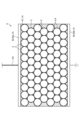
- FIG. 1 schematically shows a nonlinear resistance resin material according to a first embodiment
- FIG. Enlarged view of part A shown in FIG. FIG. 2 is a diagram schematically showing first particles and a first resin phase in Embodiment 1
- FIG. 4 is a diagram showing the current-voltage characteristics of the first particles of the nonlinear resistance resin material according to the first embodiment, the current-voltage characteristics of the material in a state close to an insulator, and the current-voltage characteristics of the material in a state close to a conductor
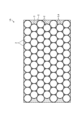
- FIG. 4 is a diagram schematically showing a nonlinear resistance resin material according to Modification 1 of Embodiment 1
- FIG. 4 is a diagram schematically showing a nonlinear resistance resin material according to Modification 2 of Embodiment 1;
- FIG. 10 is a diagram showing current-carrying paths of the nonlinear resistance resin material according to Modification 2 of Embodiment 1;
- FIG. 4 is a diagram schematically showing a nonlinear resistance resin material according to Modification 3 of Embodiment 1;
- FIG. 10 is a diagram schematically showing a connection example between the overvoltage protection device and the device to be protected according to the second embodiment, and showing when a voltage less than the threshold is applied;
- FIG. 10 is a diagram schematically showing a connection example between the overvoltage protection device and the device to be protected according to the second embodiment, and showing when a voltage equal to or higher than the threshold is applied;
- FIG. 10 is a diagram schematically showing the nonlinear resistor of the overvoltage protection device according to the second embodiment, and showing the nonlinear resistor using the nonlinear resistance resin material according to the first embodiment
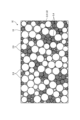
- FIG. 10 is a diagram schematically showing the nonlinear resistor of the overvoltage protection device according to the second embodiment, and showing the nonlinear resistor using the nonlinear resistance resin material according to the first modification of the first embodiment; The figure which showed typically the nonlinear resistance resin material concerning Embodiment 3.
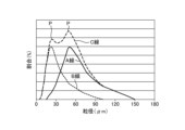
- FIG. 10 is a diagram showing the particle size distribution of first particles of the nonlinear resistance resin material according to the third embodiment
- FIG. 10 is a diagram showing the relationship between the mixing ratio of the first particles and the filling rate of the nonlinear resistance resin material according to the third embodiment;
- FIG. 10 is a diagram showing current paths of the nonlinear resistance resin material according to the third embodiment
- FIG. 10 is a diagram showing current-voltage characteristics of the first particles of the nonlinear resistance resin material according to the third embodiment and current-voltage characteristics of the first particles of the nonlinear resistance resin material according to the first embodiment
- FIG. 11 is a diagram schematically showing a nonlinear resistance resin material according to a modified example of Embodiment 3;
- nonlinear resistance resin material the nonlinear resistor, the overvoltage protection device, and the method for manufacturing the nonlinear resistance resin material according to the embodiments will be described in detail below with reference to the drawings.
- FIG. 1 is a diagram schematically showing a nonlinear resistance resin material 1 according to Embodiment 1.
- FIG. FIG. 2 is an enlarged view of part A shown in FIG.
- the nonlinear resistance resin material 1 includes a plurality of first particles 2 and a first resin phase 3 covering the surfaces of some or all of the plurality of first particles 2 .
- the first resin phase 3 covers the entire surfaces of the plurality of first particles 2 in this embodiment.
- Adjacent first particles 2 are mutually bound and electrically connected via the first resin phase 3 .
- Voids 4 are formed in portions of the nonlinear resistance resin material 1 other than the first particles 2 and the first resin phase 3 .
- a void 4 is formed between the outer edge of the nonlinear resistance resin material 1 and the first particles 2 . Moreover, as shown in FIG. 2, the void 4 is formed in a portion surrounded by three adjacent first particles 2 .
- FIG. 1 illustrates a state in which the first particles 2 having the same particle size are regularly aligned, when the first particles 2 having a plurality of particle size distributions are used, the first particles 2 of various sizes are tightly bound.
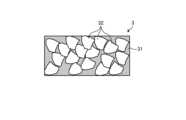
- FIG. 3 is a diagram schematically showing the first particles 2 and the first resin phase 3 in Embodiment 1.
- FIG. 4 is an enlarged view of the B section shown in FIG. 3.
- the first particles 2 shown in FIG. 3 have a non-linear resistance characteristic that exhibits insulating properties when a voltage below the threshold is applied and exhibits conductivity when a voltage above the threshold is applied. That is, the first particles 2 have the characteristic of reversibly changing between an insulator and a conductor at the threshold voltage Vth . Therefore, while general materials follow Ohm's law, the first particles 2 do not follow Ohm's law and are commonly called “varistors". In particular, a particle-shaped varistor such as the first particles 2 is called a "microvaristor".
- FIG. 5 is a diagram showing the current-voltage characteristics of the first particles 2 of the nonlinear resistance resin material 1 according to Embodiment 1, the current-voltage characteristics of the material in a state close to an insulator, and the current-voltage characteristics of a material in a state close to a conductor.
- the horizontal axis of FIG. 5 is current (A), and the vertical axis is voltage (V).
- a line L1 shown in FIG. 5 represents the current-voltage characteristics of the first particles 2.
- Line L2 shown in FIG. 5 represents the current-voltage characteristics of the material in a near-insulator state.
- Line L3 shown in FIG. 5 represents the current-voltage characteristics of the material in a state close to a conductor.
- the electrical resistance changes and the current flows abruptly at the boundary of the threshold voltage Vth beyond the small current region R indicated by the dot hatching in FIG. That is, the first particles 2 exhibit insulating properties when the applied voltage is lower than the threshold voltage Vth , but exhibit electrical conductivity when the applied voltage is higher than the threshold voltage Vth . It can be seen that the current-voltage characteristics of the first particles 2 are different from the current-voltage characteristics of the near-insulator and near-conductor states according to Ohm's law.
- the nonlinear resistance index which quantifies the nonlinear resistance characteristic in the present disclosure, represents the degree to which the electrical resistance changes abruptly at the threshold voltage Vth , is obtained from the slope of the two points of the current-voltage characteristic, and is generally represented by the following formula (1).
- Nonlinear resistance index (logI 2 -logI 1 )/(logV 2 -logV 1 ) (1)
- the nonlinear resistance characteristic is good and the non-linear resistance index is large when the current flows abruptly with the threshold voltage Vth as the boundary, as in the case of the first particle 2 indicated by the line L1 in FIG.
- the non-linear resistance characteristic is poor and the non-linear resistance index is small for a material with a low non-linear resistance characteristic and in a state close to an insulator as indicated by the line L2 in FIG.
- a material having no non-linear resistance characteristic and being in a state close to a conductor shown by line L3 in FIG. 5 has no non-linear resistance characteristic and a small non-linear resistance index.
- the first particles 2 shown in FIG. 3 a material obtained by adding a small amount of several types of subcomponents to the main component and firing the resulting material is used.
- performance such as the magnitude of the threshold voltage Vth , the volume resistance in the case of an insulator, and the nonlinear resistance characteristics can be controlled.
- Zinc oxide or silicon carbide for example, is used as the main component of the first particles 2 .
- the first particles 2 preferably contain 80 wt % or more of zinc oxide or silicon carbide.
- the main component of the first particles 2 it is preferable to use zinc oxide, which has higher nonlinear resistance characteristics than silicon carbide.
- subcomponents of the first particles 2 include bismuth oxide, antimony oxide, chromium oxide, nickel oxide, manganese oxide, cobalt oxide, and silicon oxide, and the composition is adjusted according to the application.
- the main component of the first particles 2 is zinc oxide powder.
- the main component of the first particles 2 is zinc oxide powder.
- 95.8 mol % of zinc oxide powder as the main component is weighed.
- 0.5 mol% of bismuth oxide, 1.2 mol% of antimony oxide, 0.5 mol% of chromium oxide, 0.5 mol% of nickel oxide, 0.5 mol% of manganese oxide, 0.5 mol% of cobalt oxide, and 0.5 mol% of silicon oxide are weighed as subcomponents, and the weighed subcomponents are added to the zinc oxide powder.
- These raw materials are pulverized and mixed using water as a medium.
- the raw materials are preferably pulverized and mixed so that the raw materials have the same average particle size.
- the pulverized and mixed raw material is spray-injected into a high-temperature atmosphere of 100° C. or higher to spray-dry the raw material.
- spherical granules are obtained in which raw materials such as zinc oxide powder, bismuth oxide, antimony oxide, chromium oxide, nickel oxide, manganese oxide, cobalt oxide, and silicon oxide are uniformly agglomerated.
- the granules are subsequently placed in a sagger and fired at a temperature of 1200°C. Since the granules after firing are agglomerated, they are pulverized by applying pressure to break the agglomeration.
- the first particles 2 have a spherical shape in which primary particles of zinc oxide or silicon carbide are gathered, and are actually almost spherical although there are minute irregularities.
- the particle size of the first particles 2 can be adjusted by adjusting the solid content concentration when pulverizing and mixing with water as a medium, the pressure when spraying, etc., and may be appropriately changed according to the application of the nonlinear resistance resin material 1.
- the average particle size of the primary particles that constitute the main component of the first particles 2 is preferably less than 20 ⁇ m from the viewpoint of the magnitude of the threshold voltage V th that becomes the nonlinear resistance characteristic and the adhesion to the first resin phase 3 .
- the first particles 2 zinc oxide or silicon carbide obtained by partially crushing spherical particles may be used.
- Partially pulverized means a state in which zinc oxide or silicon carbide is not pulverized to primary particles, and agglomeration of primary particles of zinc oxide or silicon carbide remains.
- the first particles 2 may be aggregates of two or more primary particles.
- the first particles 2 may be zinc oxide or silicon carbide that is partially unagglomerated.
- first particles 2 Even if such first particles 2 are used, the degree of freedom of the pressure during the crushing treatment during production is increased, so the productivity of the first particles 2 can be improved. However, if zinc oxide or silicon carbide that is partially crushed, or zinc oxide or silicon carbide that is partially unaggregated is used, the viscosity increases when mixed with the resin.
- the first resin phase 3 shown in FIG. 3 covers at least part of the surface of each first particle 2 and has semi-conductivity or conductivity. As shown in FIG. 4, the first resin phase 3 contains a first matrix resin 31 and a plurality of conductive or semiconductive second particles 32 .
- a solvent-insoluble resin may be used for the first matrix resin 31, but it is preferable to use a solvent-soluble resin such as polyvinyl alcohol resin, polyvinyl butyral, or polylactic acid.
- a solvent-soluble resin such as polyvinyl alcohol resin, polyvinyl butyral, or polylactic acid.
- water can be used as a solvent for polyvinyl alcohol resin
- ethanol can be used as a solvent for polyvinyl butyral resin
- chloroform can be used as a solvent for polylactic acid.
- a polyvinyl alcohol resin is used as the first matrix resin 31 .
- metal powder, carbon powder, and conductive ceramic powder are used for the second particles 32 .
- Carbon powder is preferably used for the second particles 32 from the viewpoint of ease of mixing. In this embodiment, carbon powder is used for the second particles 32 .
- the first resin phase 3 may cover the entire surface of the first particles 2 as shown in FIG.
- the first resin phase 3 preferably covers 50% or more of the surface of the first particles 2, and more preferably covers 70% or more of the surface of the first particles 2 from the viewpoint of binding the adjacent first particles 2 together in a post-process.
- the average particle size of the second particles 32 is preferably 1/10 or less of the average particle size of the first particles 2 . Such a size relationship makes it easier to cover the surfaces of the first particles 2 with the second particles 32 .
- each first particle 2 has a contact portion 21 that contacts the adjacent first particle 2 via the first resin phase 3 and a non-contact portion 22 that does not contact the adjacent first particle 2.
- the contact portion 21 is a portion electrically connected to the adjacent first particle 2 via the first resin phase 3 .
- the term “electrically connected” means a state in which adjacent first particles 2 are electrically connected via the first resin phase 3 .
- the contact portions 21 of adjacent first particles 2 are bound to each other via the first resin phase 3 .
- binding means that the first resin phase 3 is cured while the first resin phase 3 is in close contact with each of the adjacent first particles 2, so that the adjacent first particles 2 are connected via the first resin phase 3.
- the first resin phase 3 enters the fine unevenness of the first particles 2 and may be attached to the first particles 2 by physical bonding such as an anchor effect, or may be attached to the first particles 2 by chemical bonding such as hydrogen bonding due to the influence of moisture due to moisture absorption.
- a thin first resin phase 3 exists between the contact portions 21 of the adjacent first particles 2 .
- the volume ratio of the first particles 2 in the nonlinear resistance resin material 1 is preferably 25 vol % or more and 74 vol % or less. If the volume ratio of the second particles 32 in the first resin phase 3 is less than 1 vol %, there is a possibility that the adhesion between the first particles 2 will be insufficient due to the lack of conductive components, and the first particles 2 will approach an insulator.
- the volume ratio of the second particles 32 in the first resin phase 3 is preferably 1 vol % or more and 40 vol % or less.
- the volume ratio of the second particles 32 in the nonlinear resistance resin material 1 is preferably 0.2 vol % or more and 2 vol % or less.
- the volume of the voids 4 occupying the nonlinear resistance resin material 1 is preferably larger than the volume of the first resin phase 3 occupying the nonlinear resistance resin material 1 .
- FIG. A method of manufacturing the nonlinear resistance resin material 1 includes a mixing process, a pressure molding process, and a curing process. It should be noted that these steps are merely examples, and are not intended to limit the method of manufacturing the nonlinear resistance resin material 1 .
- the mixing step is a step of mixing a plurality of first particles 2 having a non-linear resistance characteristic that exhibits insulation when a voltage less than the threshold is applied and conductivity when a voltage equal to or higher than the threshold is applied, and a first resin phase 3 having semi-conductivity or conductivity, and covering at least a portion of the surfaces of some or all of the plurality of first particles 2 with the first resin phase 3.
- the first particles 2 shown in FIG. 3, the polyvinyl alcohol resin as the first matrix resin 31 shown in FIG. 4, and the carbon powder as the second particles 32 are weighed and then mixed.
- "GL-05" manufactured by Mitsubishi Chemical Corporation was used as the polyvinyl alcohol resin.
- the carbon powder was used as the carbon powder.
- the mixing method is not particularly limited, and may be appropriately selected from known mixing methods.
- the first particles 2, the first matrix resin 31 in a liquid state as a 5 wt % aqueous solution, and the second particles 32 are uniformly mixed using a machine. It is preferable to control the pressure during mixing so that the first particles 2 are not crushed.
- the non-linear resistance resin material 1 is obtained, which has the first particles 2 covered with the first resin phase 3 shown in FIG. 1 and which has not yet been molded.
- the pressure molding process is a process of molding the nonlinear resistance resin material 1 including the first particles 2 covered with the first resin phase 3 into a predetermined shape.
- the molding method is not particularly limited, and may be appropriately selected from known molding methods according to the shape of the nonlinear resistance resin material 1 to be produced.
- the nonlinear resistance resin material 1 having the first particles 2 covered with the first resin phase 3 may be filled in a mold, and a molding pressure may be applied to the nonlinear resistance resin material 1 by a pressing device to mold the nonlinear resistance resin material 1 into a predetermined shape.
- the nonlinear resistance resin material 1 may be molded into a predetermined shape by applying molding pressure to the nonlinear resistance resin material 1 by increasing the gas pressure.
- the nonlinear resistance resin material 1 is filled in a mold, and molding pressure is applied to the nonlinear resistance resin material 1 to mold the nonlinear resistance resin material 1 into a predetermined shape.
- the curing step is a step of heating and curing the nonlinear resistance resin material 1 molded into a predetermined shape. By heating and curing the nonlinear resistance resin material 1, adjacent first particles 2 are bound and electrically connected via the first resin phase 3 as shown in FIG.
- the curing method of the nonlinear resistance resin material 1 is not particularly limited, and may be appropriately selected from known curing methods. Through the above steps, the nonlinear resistance resin material 1 is manufactured.
- the nonlinear resistance resin material 1 includes a plurality of first particles 2 having a nonlinear resistance characteristic that exhibits insulating properties when a voltage below the threshold is applied and exhibits conductivity when a voltage above the threshold is applied, and a first resin phase 3 that includes semiconductive or conductive second particles 32 and covers at least a portion of the surfaces of some or all of the plurality of first particles 2.
- adjacent first particles 2 are mutually bound and electrically connected via the first resin phase 3 .
- the first resin phase 3 contains semiconductive or conductive second particles 32 .
- the volume ratio of the first particles 2 in the nonlinear resistance resin material 1 is 25 vol% or more and 74 vol% or less, and the volume ratio of the second particles 32 in the first resin phase 3 is 1 vol% or more and 40 vol% or less.
- the volume ratio of the second particles 32 in the nonlinear resistance resin material 1 is 0.2 vol% or more and 2 vol% or less, and the volume of the voids 4 in the nonlinear resistance resin material 1 is larger than the volume of the first resin phase 3 in the nonlinear resistance resin material 1.
- the average particle size of the second particles 32 is 1/10 or less of the average particle size of the first particles 2, the surfaces of the first particles 2 are easily covered with the second particles 32.
- the first particles 2 contain 80 wt % or more of zinc oxide or silicon carbide, so that the nonlinear resistance characteristics of the first particles 2 can be sufficiently secured.
- the first particles 2 are agglomerates of two or more primary particles, the degree of freedom of the pressure during the crushing process during manufacturing is increased, so the productivity of the first particles 2 can be improved.
- the average particle size of the primary particles that constitute the main component of the first particles 2 is less than 20 ⁇ m, so that the adhesion between the first particles 2 and the first resin phase 3 can be enhanced.
- FIG. 6 is a diagram schematically showing a nonlinear resistance resin material 1A according to Modification 1 of Embodiment 1.
- FIG. 7 is an enlarged view of the C section shown in FIG. 6.
- the nonlinear resistance resin material 1A according to Modification 1 differs from the nonlinear resistance resin material 1 of Embodiment 1 described above in that the second resin phase 5 is provided.
- the same reference numerals are given to the parts that overlap with the nonlinear resistance resin material 1 of the first embodiment, and the description thereof is omitted.
- 6 and 7 show a state in which the voids 4 in FIGS. 1 and 2 are filled with the second resin phase 5.
- FIG. In FIGS. 6 and 7, reference numerals 4 and 5 are written together for convenience of explanation.
- the second resin phase 5 fills the voids 4 formed in the portion other than the first particles 2 and the first resin phase 3 of the nonlinear resistance resin material 1A and has insulating properties.
- the volume ratio of the second resin phase 5 in the nonlinear resistance resin material 1A is preferably larger than the volume ratio of the first resin phase 3 in the nonlinear resistance resin material 1A.
- the second resin phase 5 should be incompatible with the first resin phase 3 .
- the second resin phase 5 for example, epoxy, polycarbonate, polypropylene, acrylic, phenol, polyvinyl chloride, polystyrene, unsaturated polyester, polyimide, acrylonitrile-butadiene-styrene copolymer is used. Each of these resins may be used alone, or two or more of them may be used. Also, a varnish obtained by dissolving these resins in a solvent may be used for the second resin phase 5 .
- polyvinyl alcohol is used for the first resin phase 3
- the compounding step is a step of compounding the molded nonlinear resistance resin material 1A with the second insulating resin phase 5 . That is, the second resin phase 5 in the liquid state is impregnated into the nonlinear resistance resin material 1A after the curing process, and the voids 4 are filled with the second resin phase 5 . In the compositing process, even finer voids 4 can be impregnated by carrying out under vacuum.
- a curing process is newly performed in which the nonlinear resistance resin material 1A including the second resin phase 5 is heated and cured.
- the nonlinear resistance resin material 1A fills the voids 4 formed in the portions other than the first particles 2 and the first resin phase 3, and is provided with the second resin phase 5 having insulating properties, so that a structure with even higher mechanical strength can be produced.
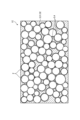
- FIG. 8 is a diagram schematically showing a nonlinear resistance resin material 1B according to Modification 2 of Embodiment 1.
- FIG. 9 is a diagram showing an energization path Z of the nonlinear resistance resin material 1B according to Modification 2 of Embodiment 1.
- the same reference numerals are given to the parts that overlap with the nonlinear resistance resin material 1 of the first embodiment, and the description thereof is omitted.
- the nonlinear resistance resin material 1B has a plurality of first particles 2 with different particle sizes.
- the average particle diameter of the first particles 2 is not particularly limited, it is 50 ⁇ m in the present embodiment.
- the first particles 2 are produced by spray-injecting the raw material described in the first embodiment and spray-drying the raw material.
- the particle size distribution of the first particles 2 can be changed by the amount of spray when spraying the raw material. The smaller the spray amount and the smaller the droplet size, the smaller the particle size of the first particles 2 .
- adjacent first particles 2 are bonded to each other via the first resin phase 3 , thereby forming an electric path Z that electrically connects the first particles 2 . This modification can also achieve the same effect as the first embodiment described above.
- FIG. 10 is a diagram schematically showing a nonlinear resistance resin material 1C according to Modification 3 of Embodiment 1.
- the nonlinear resistance resin material 1C differs from the nonlinear resistance resin material 1B according to Modification 2 of Embodiment 1 described above in that a second resin phase 5 is provided.
- the nonlinear resistance resin material 1C may include a second resin phase 5 that fills the voids 4 formed in portions other than the first particles 2 and the first resin phase 3 and has insulating properties.
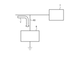
- FIG. 11 is a diagram schematically showing a connection example between the overvoltage protection device 6 and the device to be protected 7 according to the second embodiment, and shows a case where a voltage less than the threshold is applied.
- FIG. 12 is a diagram schematically showing a connection example between the overvoltage protection device 6 and the device to be protected 7 according to the second embodiment, and shows a case where a voltage equal to or higher than the threshold is applied.
- FIG. 11 is a diagram schematically showing a connection example between the overvoltage protection device 6 and the device to be protected 7 according to the second embodiment, and shows a case where a voltage equal to or higher than the threshold is applied.
- FIG. 13 is a diagram schematically showing the nonlinear resistor 61 of the overvoltage protection device 6 according to the second embodiment, and shows the nonlinear resistor 61 using the nonlinear resistance resin material 1 according to the first embodiment.
- the same reference numerals are given to the parts that overlap with the first embodiment, and the description thereof is omitted.
- the arrow Y shown in FIGS. 11 and 12 represents the flow of electricity.
- the overvoltage protection device 6 shown in FIGS. 11 and 12 is a device that prevents overvoltage from being applied to the device 7 to be protected. As shown in FIGS. 11 to 13, the overvoltage protection device 6 includes a nonlinear resistor 61 and wiring 63 electrically connected to the device 7 to be protected.
- a nonlinear resistor 61 shown in FIG. 13 includes the nonlinear resistance resin material 1 according to the first embodiment and a plurality of electrodes 62 attached to the nonlinear resistance resin material 1 .
- the shape of the nonlinear resistance resin material 1 is not particularly limited, it is columnar in this embodiment.
- the number of electrodes 62 is not particularly limited, but is two in this embodiment.
- the electrodes 62 are attached along both ends of the nonlinear resistance resin material 1 in the width direction.
- the shape of the electrode 62 is not particularly limited, it is circular in this embodiment.
- one electrode 62 is referred to as electrode 62a and the other electrode 62 is referred to as electrode 62b.
- the electrode 62a is connected to the wiring 63 and the electrode 62b is grounded.
- a silver paste that can be cured at room temperature, or an aluminum thermal spray material that has sufficient heat resistance is used.
- Non-linear resistor 61 is incorporated in overvoltage protection device 6 shown in FIGS. 11 and 12 .
- the overvoltage protection device 6 and the device to be protected 7 are electrically connected in parallel.
- one electrode 62a shown in FIG. 13 is charged and the other electrode 62b is grounded, and an overvoltage is applied to the electrode 62a on the charged side, the nonlinear resistance resin material 1 of the nonlinear resistor 61 becomes an insulator when a voltage lower than the threshold shown in FIG. I can.
- FIG. 14 is a diagram schematically showing the nonlinear resistor 61 of the overvoltage protection device 6 according to the second embodiment, and shows the nonlinear resistor 61 using the nonlinear resistance resin material 1A according to the first modification of the first embodiment.
- the nonlinear resistor 61 includes the nonlinear resistance resin material 1A according to the modified example of the first embodiment and a plurality of electrodes 62 attached to the nonlinear resistance resin material 1A. Even when the nonlinear resistance resin material 1A includes the second resin phase 5, the same effects as in the present embodiment can be obtained.
- the nonlinear resistance resin material 1 according to Embodiment 1, the nonlinear resistance resin material 1A according to Modification 1 of Embodiment 1, the nonlinear resistance resin material 1B according to Modification 2 of Embodiment 1, or the nonlinear resistance resin material 1C according to Modification 3 of Embodiment 1 can be used for the nonlinear resistor 61 that applies an electric field by providing a potential difference between the electrodes 62a and 62b so that one electrode 62a is charged and the other electrode 62b is grounded.
- FIG. 15 is a diagram schematically showing a nonlinear resistance resin material 1D according to the third embodiment.
- FIG. 16 is a diagram showing the particle size distribution of the first particles 2 of the nonlinear resistance resin material 1D according to the third embodiment.
- FIG. 17 is a diagram showing the relationship between the mixing ratio of the first particles 2 and the filling ratio of the nonlinear resistance resin material 1D according to the third embodiment.
- FIG. 18 is a diagram showing current paths Z of the nonlinear resistance resin material 1D according to the third embodiment.
- FIG. 19 is a diagram showing current-voltage characteristics of the first particles 2 of the nonlinear resistance resin material 1D according to the third embodiment and current-voltage characteristics of the first particles 2 of the nonlinear resistance resin material 1 according to the first embodiment.
- the nonlinear resistance resin material 1D according to the third embodiment is different from the nonlinear resistance resin material 1B according to the second modification of the first embodiment described above in that it includes two types of first particles 2 having different particle size distributions.
- the same reference numerals are given to the parts that overlap with the nonlinear resistance resin material 1B according to the second modification of the first embodiment, and the description thereof is omitted.
- a nonlinear resistance resin material 1D shown in FIG. 15 includes two or more types of first particles 2 having different particle size distributions.
- the nonlinear resistance resin material 1D includes two or more types of first particles 2 having different average particle diameters.
- the first particles 2 having an average particle size of 50 ⁇ m and the first particles 2 having an average particle size of 20 ⁇ m are mixed, and the particle size distribution of the first particles 2 having an average particle size of 50 ⁇ m is different from the particle size distribution of the first particles 2 having an average particle size of 20 ⁇ m.
- the first particles 2 having an average particle diameter of 50 ⁇ m may be referred to as large particles 8 and the first particles 2 having an average particle diameter of 20 ⁇ m may be referred to as small particles 9 .
- the large particles 8 are shown in white and the small particles 9 are hatched.
- the small particles 9 enter the voids 4 between the large particles 8 .
- the small particles 9 are arranged so as to fill the gaps 4 between the large particles 8 .
- the average particle size of the first particles 2 is not limited to the numerical values given as examples.
- Line A in FIG. 16 indicates the particle size distribution of the first particles 2 having an average particle size of 50 ⁇ m.
- Line B in FIG. 16 indicates the particle size distribution of the first particles 2 having an average particle size of 20 ⁇ m.
- Line C in FIG. 16 indicates the particle size distribution of the first particles 2 as a whole.
- the horizontal axis of FIG. 16 is the particle size ( ⁇ m) of the first particles 2, and the vertical axis of FIG. 16 is the ratio (%) of the first particles 2 of each particle size.
- the particle size distribution of the first particles 2 with an average particle size of 50 ⁇ m and the particle size distribution of the first particles 2 with an average particle size of 20 ⁇ m are different from each other.
- the particle size distribution of the entire first particles 2 has two maximum values P at which the proportion of the first particles 2 present is maximum.
- the particle size distribution curve has a shape having two maximum values P.
- FIG. 17 shows the relationship between the mixing ratio (vol%) of the first particles 2 having an average particle size of 50 ⁇ m and the filling rate (vol%) of the first particles 2 .
- the horizontal axis of FIG. 17 is the mixing ratio (vol %) of the first particles 2 having an average particle diameter of 50 ⁇ m
- the vertical axis of FIG. 17 is the filling rate (vol %) of the first particles 2 .
- the filling rate of the first particles 2 means the volume ratio of the first particles 2 in the nonlinear resistance resin material 1D.
- the filling rate of the first particles 2 was maximized when the mixing ratio of the first particles 2 having an average particle diameter of 50 ⁇ m was 60 vol %.
- the mixing ratio of the first particles 2 having an average particle size of 50 ⁇ m is 60 vol %
- the mixing ratio of the first particles 2 having an average particle size of 20 ⁇ m is 40 vol %.
- the nonlinear resistance resin material 1D includes two types of first particles 2 having different particle size distributions, and if the particle size distribution of the first particles 2 as a whole has two maximum values P at which the proportion of the first particles 2 present is maximized, the small particles 9 with a small particle size enter the gaps 4 between the large particles 8 with a large particle size. Therefore, the gap 4 between the adjacent first particles 2 is reduced or eliminated, so that the filling rate of the first particles 2 can be increased.
- the bonding area between the first particles 2 can be increased.
- the number of conductive paths Z electrically connecting the first particles 2 increases. That is, since the energization is performed through the bonding portion of the first particles 2, by increasing the bonding area between the first particles 2, the energization path Z electrically connecting the first particles 2 can be increased.
- the number of conducting paths Z increases, a large amount of current can flow in the current region after the threshold voltage Vth is exceeded.
- the line L1' in FIG. 19 shows the current-voltage characteristics of the first particles 2 of the nonlinear resistance resin material 1D when the mixing ratio of the first particles 2 having an average particle diameter of 50 ⁇ m is 60 vol% and the mixing ratio of the first particles 2 having an average particle diameter of 20 ⁇ m is 40 vol%, that is, when the filling rate of the first particles 2 is maximized.
- a line L1 in FIG. 19 is the same as L1 shown in FIG. 5, and shows the current-voltage characteristics of the first particles 2 of the nonlinear resistance resin material 1 according to the first embodiment.
- the slope of line L1' is smaller than the slope of line L1. In other words, in the present embodiment, the slope of line L1 can be further reduced to line L1'. Therefore, in the present embodiment, the nonlinear resistance characteristic of the nonlinear resistance resin material 1D can be further improved and the nonlinear resistance index of the nonlinear resistance resin material 1D can be further increased as compared with the first embodiment.
- FIG. 20 is a diagram schematically showing a nonlinear resistance resin material 1E according to a modified example of the third embodiment.
- the nonlinear resistance resin material 1E may include a second resin phase 5 that fills the gaps 4 formed in portions other than the first particles 2 and the first resin phase 3 and has insulating properties.
- the nonlinear resistance resin material 1D includes two types of first particles 2 with different particle size distributions in the present embodiment, it may include three or more types of first particles 2 with different particle size distributions as long as the filling rate of the first particles 2 can be increased.
- the nonlinear resistance resin material 1D may include two or more types of first particles 2 having different particle size distributions.
- the particle size distribution of the entire first particles 2 may have two or more maximum values P at which the proportion of the first particles 2 present is maximum.
- the first particles 2 with an average particle diameter of 50 ⁇ m may be covered with the first resin phase 3 containing the second particles 32, and the first particles 2 with an average particle diameter of 20 ⁇ m may not be covered with the first resin phase 3. It has been confirmed by experiments and studies by the present inventor that the current-voltage characteristics of the first particles 2 are improved from the line L1 shown in FIG. 19 toward the line L1' even in this manner. In addition, when the binding between the first particles 2 is insufficient, the first particles 2 having an average particle diameter of 20 ⁇ m as shown in FIG. 20 may be covered with the third resin phase 10 that does not contain the second particles 32.
- the composition of the third resin phase 10 may be the same as the composition of the first resin phase 3 except that it does not contain the second particles 32 .
- the first particles 2 having an average particle diameter of 50 ⁇ m may not be covered with the first resin phase 3, and the first particles 2 having an average particle diameter of 20 ⁇ m may be covered with the first resin phase 3 containing the second particles 32. It has been confirmed by experiments and studies by the present inventor that the current-voltage characteristics of the first particles 2 are improved from the line L1 shown in FIG. 19 toward the line L1' even in this manner. In addition, when the binding between the first particles 2 is insufficient, the first particles 2 having an average particle diameter of 50 ⁇ m may be covered with the third resin phase 10 that does not contain the second particles 32 .
- the nonlinear resistance resin material 1D includes two types of first particles 2 having different average particle diameters
- at least one type of the first particles 2 may be covered with the first resin phase 3 containing the second particles 32
- at least one type of the first particles 2 may not be covered with the first resin phase 3, or may be covered with the third resin phase 10 which does not contain the second particles 32.
- the amount of the first resin phase 3 containing the second particles 32 to be used can be reduced, and the amount of the first resin phase 3 containing the second particles 32 to be processed can be reduced, so that the productivity of the nonlinear resistance resin material 1D can be improved.
- At least one type of first particles 2 is not covered with the first resin phase 3, in the mixing step, at least one type of first particles 2, the first matrix resin 31 in a liquid state, and the second particles 32 are mixed to prepare the non-linear resistance resin material 1D before molding, and then another type of first particles 2 having a different average particle size is mixed into the non-linear resistance resin material 1D before molding.
- the mixing step includes a step of mixing at least one type of the first particles 2, the first matrix resin 31 in a liquid state, and the second particles 32 to prepare the non-linear resistance resin material 1D before molding, and a step of mixing another type of the first particles 2 having a different average particle size and the matrix resin in a liquid state to be the third resin phase 10 to prepare the non-linear resistance resin material 1D before molding. You can do it separately. Then, the non-linear resistance resin material 1D before molding, which is separately produced, may be mixed.
- the nonlinear resistance resin material 1D comprises three or more types of first particles 2 having different average particle diameters
- at least one type of first particles 2 may be covered with the first resin phase 3 containing the second particles 32, and at least one type of the first particles 2 may not be covered with the first resin phase 3, or may be covered with the third resin phase 10 which does not contain the second particles 32.
- the current-voltage characteristics of the first particles 2 are improved from the line L1 shown in FIG. 19 toward the line L1' even in this manner.
- the productivity of the nonlinear resistance resin material 1D can be improved.
- the nonlinear resistance resin material 1D includes the first particles 2 having one type of average particle diameter
- at least some of the first particles 2 may be covered with the first resin phase 3 containing the second particles 32, and at least some of the first particles 2 may be either not covered with the first resin phase 3 or covered with the third resin phase 10 which does not contain the second particles 32. It has been confirmed by experiments and studies by the present inventor that the current-voltage characteristics of the first particles 2 are improved from the line L1 shown in FIG. 19 toward the line L1' even in this manner.
- the productivity of the nonlinear resistance resin material 1D can be improved.
- Nonlinear resistance resin materials according to Examples 1 to 41 to which molding pressure was applied and nonlinear resistance resin materials according to Comparative Examples 1 to 8 to which molding pressure was not applied were prepared according to the blending amounts shown in Table 1.
- a polyvinyl alcohol resin (“GL-05” manufactured by Mitsubishi Chemical Corporation) was used as the first matrix resin constituting the first resin phase.
- Carbon powder (“CCE03PB” manufactured by Kojundo Chemical Laboratory Co., Ltd.) was used for the second particles constituting the first resin phase.
- An epoxy resin main agent: "CY230" manufactured by Nagase ChemteX Corporation, curing agent: "HY951” manufactured by Nagase ChemteX Corporation
- CY230 manufactured by Nagase ChemteX Corporation
- HY951 manufactured by Nagase ChemteX Corporation
- Example 1 to 41 the nonlinear resistance resin material before molding was filled in a mold, and a molding pressure of 300 kgf/cm 2 was applied to the nonlinear resistance resin material to mold the nonlinear resistance resin material.
- a molding pressure of 300 kgf/cm 2 was applied to the nonlinear resistance resin material to mold the nonlinear resistance resin material.
- the first particles are bonded together and electrically connected.
- Comparative Examples 1 to 8 in which no molding pressure was applied to the nonlinear resistance resin material, the first particles were not bound together and were not electrically connected.
- the first particles having nonlinear resistance characteristics are electrically connected and pressurized, the volume ratio of the first particles in the nonlinear resistance resin material, the volume ratio of the matrix resin of the first resin phase in the nonlinear resistance resin material, the volume ratio of the second particles in the first resin phase in the nonlinear resistance resin material, the volume ratio of the voids or the second resin phase in the nonlinear resistance resin material, and the volume ratio of the first resin phase in the first resin phase.
- the volume ratio of the second particles and the average particle size of the second particles to the first particles are changed.
- the nonlinear resistance characteristics, strength, and discharge initiation electric field were measured by the test methods shown below, and the nonlinear resistance characteristics, strength, and discharge initiation electric field were evaluated. Each evaluation was described in five steps. A higher number indicates better, a lower number indicates worse, and 3 or more indicates an acceptable range.
- the nonlinear resistance characteristic was represented by a nonlinear resistance index.
- Non-linear resistance index While applying a voltage to the obtained nonlinear resistance resin material, the current-voltage characteristics were obtained by measuring the value of the applied current, and the nonlinear resistance index was calculated.
- Example 5 Example 6, Example 11, Example 28, Example 29, Example 30, Example 31, Example 32, Example 33, Example 34, and Example 35 in which the volume ratio of the first particles in the nonlinear resistance resin material is not 25 vol% or more and 74 vol% or less, or the volume ratio of the second particles in the first resin phase is not 1 vol% or more and 40 vol% or less
- the nonlinear resistance index is 3.
- Example 39, and Example 40 had a nonlinear resistance index of 5. From this, it was found that the volume ratio of the second particles in the nonlinear resistance resin material is 0.2 vol% or more and 2 vol% or less, and the volume of the voids or the second resin phase is larger than the volume of the first resin phase, which is effective for improving the nonlinear resistance characteristics.
- Example 1 The difference between Example 1 and Example 36 is the average particle size of the second particles with respect to the first particles.
- Example 7 and Example 37 differ in average particle size of the second particles with respect to the first particles.
- the nonlinear resistance index was 5
- Example 36 in which the average particle diameter of the second particles exceeded 1/10 of the average particle diameter of the first particles, the nonlinear resistance index was 4.
- Example 7 in which the average particle diameter of the second particles was 1/10 or less of the average particle diameter of the first particles, the nonlinear resistance index was 4, whereas in Example 37 in which the average particle diameter of the second particles exceeded 1/10 of the average particle diameter of the first particles, the nonlinear resistance index was 3. From this, it was found that the average particle diameter of the second particles being 1/10 or less of the average particle diameter of the first particles is effective in improving the nonlinear resistance characteristics.
- Example 1 and Example 40 The difference between Example 1 and Example 40 is whether the voids are filled with the second resin phase or the voids are not filled.
- Example 7 and Example 41 the difference between Example 7 and Example 41 is whether the voids are filled with the second resin phase or the voids are not filled with the second resin phase.
- Example 1 in which the voids were not filled with the second resin phase, the strength and discharge starting electric field were 3
- Example 40 in which the voids were filled with the second resin phase, the strength and discharge starting electric field were 5.
- Example 7 In which the voids were not filled with the second resin phase, the strength and the electric discharge starting electric field were 4, whereas in Example 41, in which the voids were filled with the second resin phase, the strength and electric discharge starting electric field were 5. From this, it was found that filling the voids with the second resin phase is effective in improving the strength and discharge characteristics.
- Example 40 and Comparative Example 7 and the difference between Example 41 and Comparative Example 8 are only the presence or absence of pressurization in the state where the second resin phase is provided.
- both Examples 40 and 41 and Comparative Examples 7 and 8 the strength and discharge starting electric field can be maintained at a high level by providing the second resin phase.
- Comparative Examples 7 and 8 in which molding pressure was not applied to the nonlinear resistance resin material the first particles were not bound to each other and were not electrically connected, so the nonlinear resistance index was smaller than that of Examples 40 and 41.
Landscapes
- Engineering & Computer Science (AREA)
- Microelectronics & Electronic Packaging (AREA)
- Physics & Mathematics (AREA)
- Electromagnetism (AREA)
- Manufacturing & Machinery (AREA)
- Thermistors And Varistors (AREA)
Priority Applications (3)
| Application Number | Priority Date | Filing Date | Title |
|---|---|---|---|
| EP22922184.1A EP4471097A4 (en) | 2022-01-24 | 2022-12-21 | NONLINEAR RESISTIVE RESIN MATERIAL, NONLINEAR RESISTIVE BODY, OVERVOLTAGE PROTECTION DEVICE, AND METHOD FOR MANUFACTURING NONLINEAR RESISTIVE RESIN MATERIAL |
| JP2023575151A JP7657331B2 (ja) | 2022-01-24 | 2022-12-21 | 非線形抵抗樹脂材料、非線形抵抗体、過電圧保護装置および非線形抵抗樹脂材料の製造方法 |
| US18/730,305 US20250104892A1 (en) | 2022-01-24 | 2022-12-21 | Nonlinear-resistance resin material, nonlinear resistor, overvoltage protector, and manufacturing method of nonlinear-resistance resin material |
Applications Claiming Priority (2)
| Application Number | Priority Date | Filing Date | Title |
|---|---|---|---|
| JPPCT/JP2022/002377 | 2022-01-24 | ||
| JP2022002377 | 2022-01-24 |
Publications (1)
| Publication Number | Publication Date |
|---|---|
| WO2023140034A1 true WO2023140034A1 (ja) | 2023-07-27 |
Family
ID=87348203
Family Applications (1)
| Application Number | Title | Priority Date | Filing Date |
|---|---|---|---|
| PCT/JP2022/047193 Ceased WO2023140034A1 (ja) | 2022-01-24 | 2022-12-21 | 非線形抵抗樹脂材料、非線形抵抗体、過電圧保護装置および非線形抵抗樹脂材料の製造方法 |
Country Status (4)
| Country | Link |
|---|---|
| US (1) | US20250104892A1 (https=) |
| EP (1) | EP4471097A4 (https=) |
| JP (1) | JP7657331B2 (https=) |
| WO (1) | WO2023140034A1 (https=) |
Citations (5)
| Publication number | Priority date | Publication date | Assignee | Title |
|---|---|---|---|---|
| JP2002506578A (ja) * | 1998-04-27 | 2002-02-26 | エー ビー ビー リサーチ リミテッド | バリスター特性を有する非線形抵抗及びこの抵抗の製造方法 |
| JP2014013786A (ja) * | 2012-07-03 | 2014-01-23 | Toshiba Corp | 非直線抵抗材料およびその製造方法 |
| JP2015101714A (ja) | 2013-11-28 | 2015-06-04 | 株式会社東芝 | 非直線抵抗樹脂材料 |
| JP2016134605A (ja) * | 2015-01-22 | 2016-07-25 | 株式会社東芝 | 複合樹脂及び電子デバイス |
| JP2017069232A (ja) * | 2015-09-28 | 2017-04-06 | 住友ベークライト株式会社 | 熱硬化性樹脂シートおよび半導体装置の製造方法 |
Family Cites Families (6)
| Publication number | Priority date | Publication date | Assignee | Title |
|---|---|---|---|---|
| US6232866B1 (en) * | 1995-09-20 | 2001-05-15 | The United States Of America As Represented By The Administrator Of The National Aeronautics And Space Administration | Composite material switches |
| ATE403935T1 (de) * | 2004-04-06 | 2008-08-15 | Abb Research Ltd | Elektrisches nichtlineares material für anwendungen mit hoher und mittlerer spannung |
| US9082622B2 (en) * | 2010-02-26 | 2015-07-14 | Littelfuse, Inc. | Circuit elements comprising ferroic materials |
| JP6119005B2 (ja) * | 2013-09-26 | 2017-04-26 | 音羽電機工業株式会社 | 非オーム性を有する樹脂材料及びその製造方法、並びに該樹脂材料を用いた非オーム性抵抗体 |
| TWI508258B (zh) * | 2013-12-19 | 2015-11-11 | 矽品精密工業股份有限公司 | 半導體封裝件及其製法 |
| US12206234B2 (en) * | 2022-09-20 | 2025-01-21 | Ripd Ip Development Ltd | Overvoltage protection device modules |
-
2022
- 2022-12-21 WO PCT/JP2022/047193 patent/WO2023140034A1/ja not_active Ceased
- 2022-12-21 JP JP2023575151A patent/JP7657331B2/ja active Active
- 2022-12-21 EP EP22922184.1A patent/EP4471097A4/en not_active Withdrawn
- 2022-12-21 US US18/730,305 patent/US20250104892A1/en active Pending
Patent Citations (5)
| Publication number | Priority date | Publication date | Assignee | Title |
|---|---|---|---|---|
| JP2002506578A (ja) * | 1998-04-27 | 2002-02-26 | エー ビー ビー リサーチ リミテッド | バリスター特性を有する非線形抵抗及びこの抵抗の製造方法 |
| JP2014013786A (ja) * | 2012-07-03 | 2014-01-23 | Toshiba Corp | 非直線抵抗材料およびその製造方法 |
| JP2015101714A (ja) | 2013-11-28 | 2015-06-04 | 株式会社東芝 | 非直線抵抗樹脂材料 |
| JP2016134605A (ja) * | 2015-01-22 | 2016-07-25 | 株式会社東芝 | 複合樹脂及び電子デバイス |
| JP2017069232A (ja) * | 2015-09-28 | 2017-04-06 | 住友ベークライト株式会社 | 熱硬化性樹脂シートおよび半導体装置の製造方法 |
Non-Patent Citations (1)
| Title |
|---|
| See also references of EP4471097A4 |
Also Published As
| Publication number | Publication date |
|---|---|
| EP4471097A4 (en) | 2025-08-27 |
| JPWO2023140034A1 (https=) | 2023-07-27 |
| US20250104892A1 (en) | 2025-03-27 |
| JP7657331B2 (ja) | 2025-04-04 |
| EP4471097A1 (en) | 2024-12-04 |
Similar Documents
| Publication | Publication Date | Title |
|---|---|---|
| CN1681052B (zh) | 用于中高电压应用的非线性电气材料 | |
| AU629592B2 (en) | Electrical overstress pulse protection | |
| CN1145981C (zh) | 具有可变电阻性能的非线性电阻及其制造方法 | |
| JP2003049084A (ja) | 非直線性電流ー電圧ー特性曲線を有するポリマー配合物及びポリマー配合物の製造方法 | |
| US20080152898A1 (en) | Varistor-based field control tape | |
| JP2000503454A (ja) | 電気応力の制御 | |
| CN103080237B (zh) | 具有非线性电流-电压特性的组合物 | |
| JP6119005B2 (ja) | 非オーム性を有する樹脂材料及びその製造方法、並びに該樹脂材料を用いた非オーム性抵抗体 | |
| US9424967B2 (en) | Voltage-limiting composition | |
| US10950372B2 (en) | Surface mounted fuse device having positive temperature coefficient body | |
| JP6338686B2 (ja) | 電気機械用のコロナシールド系、特に外側コロナシールド系 | |
| WO2023140034A1 (ja) | 非線形抵抗樹脂材料、非線形抵抗体、過電圧保護装置および非線形抵抗樹脂材料の製造方法 | |
| TW200834612A (en) | Polymeric positive temperature coefficient thermistor and process for preparing the same | |
| ITMI20002695A1 (it) | Composizioni di polimero conduttivo contenenti fibre fibrillate e dispositivi | |
| US20240105364A1 (en) | Vacuum valve and method for manufacturing same | |
| US10790074B1 (en) | PTC circuit protection device | |
| JP4091402B2 (ja) | 電界緩和材料及びこの材料を用いた電界緩和部材並びに電磁コイル | |
| KR20090103491A (ko) | 저저항 폴리머 피티씨 써미스터 소자 및 그 제조방법 | |
| CN1278340C (zh) | 一种高分子ptc热敏电阻器及其制造方法 | |
| EP2709116B1 (en) | Nonlinear resistive element | |
| JPWO2023140034A5 (https=) | ||
| US20150103464A1 (en) | Static-protective component and static-protective composition | |
| JP4299215B2 (ja) | 有機質ptcサーミスタ | |
| JPH115915A (ja) | 導電性組成物 | |
| MXPA98005747A (en) | Control of electrical effort |
Legal Events
| Date | Code | Title | Description |
|---|---|---|---|
| 121 | Ep: the epo has been informed by wipo that ep was designated in this application |
Ref document number: 22922184 Country of ref document: EP Kind code of ref document: A1 |
|
| WWE | Wipo information: entry into national phase |
Ref document number: 2023575151 Country of ref document: JP |
|
| WWE | Wipo information: entry into national phase |
Ref document number: 18730305 Country of ref document: US |
|
| NENP | Non-entry into the national phase |
Ref country code: DE |
|
| ENP | Entry into the national phase |
Ref document number: 2022922184 Country of ref document: EP Effective date: 20240826 |
|
| WWP | Wipo information: published in national office |
Ref document number: 18730305 Country of ref document: US |
|
| WWW | Wipo information: withdrawn in national office |
Ref document number: 2022922184 Country of ref document: EP |