WO2023136356A1 - シールド部材及びワイヤハーネス - Google Patents
シールド部材及びワイヤハーネス Download PDFInfo
- Publication number
- WO2023136356A1 WO2023136356A1 PCT/JP2023/001064 JP2023001064W WO2023136356A1 WO 2023136356 A1 WO2023136356 A1 WO 2023136356A1 JP 2023001064 W JP2023001064 W JP 2023001064W WO 2023136356 A1 WO2023136356 A1 WO 2023136356A1
- Authority
- WO
- WIPO (PCT)
- Prior art keywords
- metal foil
- shield member
- bending
- corrugated tube
- amount
- Prior art date
- Legal status (The legal status is an assumption and is not a legal conclusion. Google has not performed a legal analysis and makes no representation as to the accuracy of the status listed.)
- Ceased
Links
Images


Classifications
-
- H—ELECTRICITY
- H01—ELECTRIC ELEMENTS
- H01B—CABLES; CONDUCTORS; INSULATORS; SELECTION OF MATERIALS FOR THEIR CONDUCTIVE, INSULATING OR DIELECTRIC PROPERTIES
- H01B7/00—Insulated conductors or cables characterised by their form
-
- H—ELECTRICITY
- H02—GENERATION; CONVERSION OR DISTRIBUTION OF ELECTRIC POWER
- H02G—INSTALLATION OF ELECTRIC CABLES OR LINES, OR OF COMBINED OPTICAL AND ELECTRIC CABLES OR LINES
- H02G3/00—Installations of electric cables or lines or protective tubing therefor in or on buildings, equivalent structures or vehicles
- H02G3/02—Details
- H02G3/04—Protective tubing or conduits, e.g. cable ladders or cable troughs
-
- H—ELECTRICITY
- H05—ELECTRIC TECHNIQUES NOT OTHERWISE PROVIDED FOR
- H05K—PRINTED CIRCUITS; CASINGS OR CONSTRUCTIONAL DETAILS OF ELECTRIC APPARATUS; MANUFACTURE OF ASSEMBLAGES OF ELECTRICAL COMPONENTS
- H05K9/00—Screening of apparatus or components against electric or magnetic fields
Definitions
- the present invention relates to shield members and wire harnesses.
- shielding members have been proposed to protect electric wires from external noise and the like.
- Braided conductors and metal foils are known as such shield members.
- a braided conductor is obtained by braiding wires such as metal wires into a tubular shape, and a metal foil is obtained by stretching a metal into a thin film.
- the braided conductor generally requires high manufacturing costs because it requires braiding of the wire rod.
- Metal foil on the other hand, does not require knitting and is advantageous in terms of manufacturing costs, but generally tends to crack (in other words, tear) due to bending or vibration.
- This cable includes an electric wire, a wrinkled metal foil arranged so as to surround the electric wire, and a sheath provided so as to surround the outer periphery of the metal foil.
- the wrinkles of the metal foil absorb the stretching and compression that occur in the metal foil when the cable is bent, thereby suppressing cracking of the metal foil.
- One of the objects of the present invention is to provide a wire harness having a shield member and excellent in productivity, and a shield member applicable to the wire harness and capable of appropriately suppressing cracking of metal foil. to do.
- the shield member and wire harness according to the present invention are characterized as follows.
- a resin pipe configured such that first concave portions and first convex portions extending in the circumferential direction are alternately arranged in the longitudinal direction; a metal foil provided so as to surround the outer periphery of the resin pipe and wrinkled so that second concave portions and second convex portions extending in the circumferential direction are alternately repeated and arranged in the longitudinal direction; a tape member provided to surround the outer periphery of the metal foil; A shield member comprising The metal foil is When the resin pipe is bent, the adjacent first protrusions are in contact with each other at the bend inner portion of the resin pipe.
- the amount of decrease in the length of the bend inner portion of the resin pipe is equal to or less than the compressible amount of the metal foil corresponding to the bend inner portion.
- FIG. 1 is a perspective view showing a wire harness according to an embodiment of the invention.
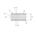
- 2A is a partial side view of the shield member shown in FIG. 1, and is a partial side view showing a state in which the shield member is not bent.
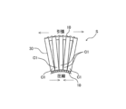
- FIG. 2B is a partial side view of the shield member shown in FIG. 1, and is a partial side view showing a state in which the shield member is bent to the maximum.
- FIG. 3 is an enlarged view showing unevenness of the metal foil shown in FIG. 2A.
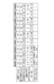
- FIG. 4 is a table showing the results of bending endurance tests performed on the shield members of Examples 1-3 and Comparative Examples 1-6.
- FIG. 1 is a perspective view showing a wire harness 1 according to an embodiment of the invention.
- the wire harness 1 includes electric wires W and a shield member S.
- the shield member S includes a corrugated tube (resin pipe) 30 , a metal foil 10 and a pressing tape (tape member) 20 .
- the electric wire W includes a conductor made of, for example, copper, aluminum, or an alloy thereof, and an insulating coating that coats the conductor.
- the electric wire W shown in FIG. 1 is a single wire having a single strand, but may be a twisted wire in which a plurality of strands are twisted together. Although two electric wires W are used in FIG. 1, one or three or more electric wires W may be used.
- the corrugated tube 30 is a cylindrical tube formed so that circumferentially extending concave portions C2 and convex portions C1 are alternately repeated and arranged in the longitudinal direction.
- the corrugated tube 30 is made of resin, and is arranged so as to surround the electric wire W, for example, by inserting the electric wire W into its tube.
- the metal foil 10 is a thin film member made of a conductive metal, and is provided in the form of a vertical winding (hereinafter simply referred to as "vertical winding") on the outside of the corrugated tube 30.
- the metal foil 10 is wrinkled to have a concave portion F2 and a convex portion F1.
- the metal foil 10 is configured such that circumferentially extending concave portions F2 and convex portions F1 are alternately repeated and arranged in the longitudinal direction of the corrugated tube 30 .
- the circumferential direction in which the concave portion F2 and the convex portion F1 extend is a direction orthogonal to the longitudinal direction.
- the wrinkling process is performed by pressing the thin film member, which is the original fabric of the metal foil 10, against a jig (such as a mold) having irregularities at a predetermined pitch.
- a jig such as a mold
- various parameters specifically, the number of unevenness per unit length, the distance D1 in the longitudinal direction between the protrusions F1, the length of the groove inner surface of the recess F2) regarding the protrusion F1 and the recess F2 described later
- the height D2, the height T2, and the radius of curvature R2 of the bottom end of the recess F2 can be set to desired values.
- the pressing tape 20 has a base material layer and an adhesive layer, and is wound around the metal foil 10 so as to surround the outer periphery of the metal foil 10 with the adhesive layer on the inside.
- the pressing tape 20 is wound around the metal foil 10 in an appropriate form (that is, winding method) such as vertical attachment or spiral winding.
- the pressing tape 20 is made of a material that is more stretchable than the metal foil 10 . Since the pressing tape 20 is sufficiently flexible as compared with the metal foil 10, the expansion and contraction of the metal foil 10 suppresses cracking of the metal foil 10 as described later. have no effect.
- FIG. 2A is a partial side view of the shield member S shown in FIG. 1, showing a state in which the shield member S is not bent.
- FIG. 2B is a partial side view of the shield member S shown in FIG. 1, showing a state where the bending of the shield member S is maximum.
- 2A and 2B from the viewpoint of making the explanation easier to understand, the cross section of the metal foil 10 is shown, and the illustration of the holding tape 20 is omitted.
- the corrugated tube 30 is configured such that concave portions C2 and convex portions C1 are alternately arranged in the longitudinal direction.
- the metal foil 10 is configured such that the concave portions F2 and the convex portions F1 are alternately arranged in the longitudinal direction.
- the shield member S can be integrally bent according to the unevenness of the corrugated tube 30 . For example, when the shield member S is bent as shown in FIG. 2B, the distance between the adjacent protrusions F1 of the metal foil 10 (that is, the distance in FIG.
- the metal foil 10 is stretched so that the depth of the concave portion F2 (that is, the uneven height T2 from the bottom end of the concave portion F2 to the tip of the convex portion F1 in FIG. 3) decreases.
- the metal foil 10 is compressed so that the distance between the adjacent protrusions F1 of the metal foil 10 (that is, the distance D1 in FIG. 3) is narrowed. be done.
- the state in which the adjacent protrusions C1 of the corrugated tube 30 are in contact with each other in the bending inner portion is referred to as the "maximum bending state.”
- the metal foil 10 secures an extension amount in the bending outer portion and a compression amount in the bending inner portion.
- a plurality of concave portions F2 and convex portions F1 are provided.
- the amount of increase in the length of the outer bend portion of the corrugated tube 30 is equal to or less than the stretchable amount of the metal foil 10 corresponding to the outer bend portion, and the length of the inner bend portion of the corrugated tube 30 is increased.
- the metal foil 10 is configured such that the amount of decrease is less than or equal to the compressible amount of the metal foil 10 corresponding to the inner bend portion. This point will be described in detail below.
- FIG. 3 is an enlarged view showing the concave portion F2 and the convex portion F1 of the metal foil 10 shown in FIG. 2A.
- D1 the distance in the longitudinal direction between the adjacent convex portions F1 of the metal foil 10 (in other words, the concave portions The width of the opening of F2 in the longitudinal direction) is defined as D1.
- D2 the length of the groove inner surface of the recess F2 in the cross section along the axis AX (see FIG. 2A) of the corrugated tube 30 (in other words, until the recess F2 disappears when the uneven height T2 becomes zero)
- D2 be the distance D1) when the metal foil 10 is stretched straight.
- the metal foil 10 is configured so as to "ensure the amount of stretching of the metal foil 10 at the bending outer portion of the corrugated tube 30 in the maximum bending state" will be explained. Specifically, when the shield member S of unit length is in the maximum bending state, the arc distance of the bending outer portion of the corrugated tube 30 is assumed to be "unit length + L1". At this time, if the relational expression “L1 ⁇ (D2 ⁇ D1) ⁇ a” is satisfied, it can be said that “the amount of stretching is ensured”. a is the number of recesses F2 per unit length when the shield member S is not bent.
- the definition that the metal foil 10 is configured so as to "secure the amount of compression of the metal foil 10 at the bending inner portion of the corrugated tube 30 in the maximum bending state" will be explained. Specifically, it is assumed that when the shield member S of unit length is in the maximum bending state, the arc distance of the bending inner portion of the corrugated tube 30 becomes "unit length - M1". At this time, if the relational expression “M1 ⁇ D1 ⁇ a” is satisfied, it can be said that “the amount of compression is ensured”. a is the number of recesses F2 in the unit length when the shield member S is not bent.
- the diameter of the corrugated tube 30 (specifically, the outer diameter of the corrugated tube 30 in a cross section orthogonal to the longitudinal direction of the corrugated tube 30 and passing through the convex portion C1) is T1 (see FIG. 2A).
- T2 (see FIG. 3) be the uneven height from the bottom end of the concave portion F2 of the metal foil 10 to the tip end of the convex portion F1 in the radial direction of the corrugated tube 30 .
- R2 be the radius of curvature of the bottom end of the concave portion F2 of the metal foil 10 in the cross section along the axis AX of the corrugated tube 30 (see FIG. 3).
- the shield member S when the bending degree S1 of the corrugated tube 30 is greater than the bending degree S2 of the concave portion F2 of the metal foil 10 (that is, when S1>S2), the shield member S It has been confirmed that the effect of suppressing cracking of the metal foil 10 when repeatedly bent is improved.
- the value of the bending radius R1 which is the bending limit of a general corrugated tube (that is, reaches the maximum bending state)
- the bending degree S1 of the corrugated tube 30 at the bending limit may be approximately calculated.
- the number of protrusions and recesses of the metal foil 10 per unit length in the longitudinal direction is equal to or greater than the number of protrusions and recesses of the corrugated tube 30 per unit length.
- the number of protrusions and recesses may be the number of protrusions, the number of recesses, or the number of sets when the protrusions and recesses are regarded as one set.
- the unevenness height T2 of the metal foil 10 tends to be lower than the unevenness height of the corrugated tube 30, in order to suppress cracking of the metal foil 10 due to tension or compression using the unevenness of the metal foil 10, It is considered preferable that the number of protrusions and recesses of the metal foil 10 is at least equal to or greater than the number of protrusions and recesses of the corrugated tube 30 .
- FIG. 4 is a table showing the results of bending endurance tests performed on the shield members of Examples 1-3 and Comparative Examples 1-6.
- the metal foil 10 used in the shield member S of Examples 1 to 3 and Comparative Examples 1 to 6 was a rolled copper foil (C1100 manufactured by JX Metals Co., Ltd., thickness 35 ⁇ m) on a jig having irregularities at a predetermined pitch.
- the convex portion F1 and the concave portion F2 are formed to have the concave-convex height T2 and the curvature radius R2 shown in FIG.
- the unevenness height T2 of the metal foil 10 is 0.035 mm
- the curvature radius R2 of the bottom end of the recessed portion F2 is 0.5 mm.
- Example 3 the unevenness height T2 of the metal foil 10 is 0.02 mm, and the curvature radius R2 of the bottom end of the recessed portion F2 is 0.05 mm.
- the unevenness height T2 was 0.035 mm, and the curvature radius R2 of the bottom end of the recess F2 was 0 mm (that is, D1 in FIG. is completely folded at the center).
- the unevenness height T2 is 0.035 mm, and the curvature radius R2 of the bottom end of the recessed portion F2 is 0.05 mm.
- the unevenness height T2 was 0.02 mm, and the curvature radius R2 of the bottom end of the recess F2 was 0 mm (that is, D1 in FIG. 3 was 0 mm, and the recess F2 fully folded).
- the unevenness height T2 is 0.02 mm, and the curvature radius R2 of the bottom end of the recess F2 is 0.02 mm.
- the metal foil 10 "secures the stretching amount by which the metal foil 10 is stretched at the bending outer portion of the corrugated tube 30 in the maximum bending state" as described above. and the condition of "securing the amount of compression by which the metal foil 10 is compressed in the bending inner portion of the corrugated tube 30 in the maximum bending state" are satisfied.
- Comparative Examples 1, 3, and 5 since the curvature radius R2 of the bottom end of the concave portion F2 is 0 mm (that is, D1 in FIG. 3 is 0 mm), at least the latter condition (compression amount guarantee) is not satisfied.
- the metal foils 10 of Examples 1 and 3 and Comparative Examples 1, 2, 5 and 6 as described above were wound vertically around a corrugated tube having a diameter T1 (outer diameter) of 12 mm. Further, a shielding member S was prepared by winding a general pressing tape 20 so as to surround the outer circumference of the metal foil 10 . A bending endurance test was performed on the prepared shield member S. Specifically, the shield member S having a predetermined length was repeatedly bent at an angle of 180 degrees at a bending speed of 30 rpm using a mandrel having a bending radius of 24 mm.
- the metal foils 10 of Example 2 and Comparative Examples 3 and 4 were wound vertically around a corrugated tube having a diameter T1 (outer diameter) of 16 mm. Further, a shielding member S was prepared by winding a general pressing tape 20 so as to surround the outer circumference of the metal foil 10 . A bending endurance test was performed on the prepared shield member S. Specifically, using a mandrel having a bending radius of 32 mm, the shield member S of a predetermined length was repeatedly bent at an angle of 180 degrees at a bending speed of 30 rpm.
- the corrugated tube 30, the wrinkled metal foil 10, and the pressing tape 20 form the shield member S.
- the wire harness 1 can be manufactured simply by attaching the shield member S to the electric wire W.
- the wire harness 1 can be manufactured in one process for attaching the shield member S to the electric wires W, as compared with the conventional cable described above which requires two processes to manufacture the cable. Therefore, productivity of the wire harness 1 can be improved.
- the metal foil 10 has a plurality of unevennesses for securing the amount of stretching in the outer portion of the bend in the maximum bending state and securing the amount of compression in the inner portion of the bending in the maximum bending state. formed. Therefore, it is possible to prevent the metal foil 10 from being stretched or compressed when the shield member S is bent, thereby preventing the metal foil 10 from being cracked. Furthermore, since the bending degree S1 of the corrugated tube 30 is greater than the bending degree S2 of the metal foil 10, the bending degree S2 to the metal foil 10 is relatively small. This can improve the effect of suppressing cracking of the metal foil 10 when the shield member S is repeatedly bent.
- the number of unevennesses of the metal foil 10 in a unit length of the corrugated tube 30 in the longitudinal direction is equal to or greater than the number of unevennesses of the corrugated tube 30 in that unit length.
- the productivity of the wire harness 1 including the shield member S that suppresses cracking of the metal foil 10 by tension or compression can be improved.
- the present invention is not limited to the above embodiments, and various modifications can be adopted within the scope of the present invention.
- the present invention is not limited to the above-described embodiments, and can be modified, improved, etc. as appropriate.
- the material, shape, size, number, location, etc. of each component in the above-described embodiment are arbitrary and not limited as long as the present invention can be achieved.
- the metal foil 10 is vertically attached to the corrugated tube 30 .
- the metal foil 10 may be provided on the corrugated tube 30 by other winding methods such as spiral winding.
- the metal foils 10 are provided so that the ends of the metal foils 10 in the circumferential direction have a laminated lap portion.
- the metal foil 10 may be provided so as not to have a wrap portion.
- the wire harness of the present invention has a shield member and is excellent in productivity, and the shield member of the present invention can be applied to the wire harness and can appropriately suppress cracking of the metal foil.
- the present invention having this effect can be used, for example, as a wire harness mounted on an automobile or the like.
- Wire harness 10 Metal foil 20: Holding tape (tape member) C1: convex portion (first convex portion) C2: concave portion (first concave portion) 30: corrugated tube (resin pipe) F1: convex portion (second convex portion) F2: concave portion (second concave portion) S: Shield member W: Electric wire
Landscapes
- Engineering & Computer Science (AREA)
- Microelectronics & Electronic Packaging (AREA)
- Architecture (AREA)
- Civil Engineering (AREA)
- Structural Engineering (AREA)
- Details Of Indoor Wiring (AREA)
- Insulated Conductors (AREA)
- Shielding Devices Or Components To Electric Or Magnetic Fields (AREA)
Abstract
シールド部材(S)は、樹脂管(30)と、シワ加工が施された金属箔(10)と、テープ部材(20)と、を備える。樹脂管(30)の最大曲げ状態において、曲げ外側部分の長さの増大量が金属箔(10)の引き延ばし可能量以下であり、且つ、曲げ内側部分の長さの減少量が金属箔(10)の圧縮可能量以下である。金属箔(10)の第2凹部(F1)及び第2凸部(F2)の凹凸高さをTとし、第2凹部(F1)の底端の曲率半径をRとした場合に、曲げ度合いS=T/(2×R+T)が1/5よりも小さい。
Description
本発明は、シールド部材及びワイヤハーネスに関する。
従来から、電線を外来ノイズ等から保護するシールド部材が提案されている。このようなシールド部材として、編組導体や金属箔が知られている。編組導体は、金属線等の線材を筒状に編み合わせたものであり、金属箔は、金属を薄膜状に引き延ばしたものである。
ここで、編組導体は、線材の編み加工が必要であることから、一般に製造コストが高い。一方、金属箔は、編み加工の必要がなく製造コストの点で有利であるが、一般に曲げや振動によって割れ(別の言い方をすると、破れ)が生じ易い。
そこで、シワ加工を施した金属箔をシールド部材として用いたケーブルが提案されている(例えば、特許文献1を参照)。このケーブルは、電線と、電線の外周を取り囲むように配置されたシワ加工を施した金属箔と、金属箔の外周を取り囲むように設けられたシースと、を備えている。このケーブルでは、ケーブルが曲がるときに金属箔に生じる引き延ばしや圧縮を金属箔のシワで吸収することで、金属箔の割れを抑制するようになっている。
特許文献1に記載のケーブルを製造するには、シワ加工を施した金属箔を電線に取り付ける工程と、金属箔が取り付けられた電線に更にシースを設ける工程と、の2つの工程を要する。しかし、例えば、生産性を向上する等の観点では、金属箔の割れを抑制する効果を損なうことなく、これら工程を1つの工程にまとめることが望ましい。
本発明の目的の一つは、シールド部材を備えて生産性に優れたワイヤハーネス、及び、そのワイヤハーネスに適用可能であって金属箔の割れを適正に抑制することが可能なシールド部材を提供することにある。
前述した目的を達成するために、本発明に係るシールド部材及びワイヤハーネスは、以下を特徴としている。
周方向に延びる第1凹部と第1凸部とが交互に繰り返して長手方向に並ぶように構成される樹脂管と、
前記樹脂管の外周を取り囲むように設けられ、前記周方向に延びる第2凹部と第2凸部とが交互に繰り返して前記長手方向に並ぶようにシワ加工が施された金属箔と、
前記金属箔の外周を取り囲むように設けられるテープ部材と、
を備えるシールド部材であって、
前記金属箔は、
前記樹脂管を曲げたときに隣接する前記第1凸部同士が前記樹脂管の曲げ内側部分において接触することになる最大曲げ状態において、前記樹脂管の曲げ外側部分の長さの増大量が前記曲げ外側部分に対応する当該金属箔の引き延ばし可能量以下であり、且つ、前記樹脂管の前記曲げ内側部分の長さの減少量が前記曲げ内側部分に対応する当該金属箔の圧縮可能量以下であるように、構成され、
前記金属箔の前記第2凹部の底端から前記第2凸部の突端までの径方向における高さをT2とし、前記第2凹部の前記底端の曲率半径をR2とした場合に、曲げ度合いS2=T2/(2×R2+T2)が1/5よりも小さい、
シールド部材であること。
前記樹脂管の外周を取り囲むように設けられ、前記周方向に延びる第2凹部と第2凸部とが交互に繰り返して前記長手方向に並ぶようにシワ加工が施された金属箔と、
前記金属箔の外周を取り囲むように設けられるテープ部材と、
を備えるシールド部材であって、
前記金属箔は、
前記樹脂管を曲げたときに隣接する前記第1凸部同士が前記樹脂管の曲げ内側部分において接触することになる最大曲げ状態において、前記樹脂管の曲げ外側部分の長さの増大量が前記曲げ外側部分に対応する当該金属箔の引き延ばし可能量以下であり、且つ、前記樹脂管の前記曲げ内側部分の長さの減少量が前記曲げ内側部分に対応する当該金属箔の圧縮可能量以下であるように、構成され、
前記金属箔の前記第2凹部の底端から前記第2凸部の突端までの径方向における高さをT2とし、前記第2凹部の前記底端の曲率半径をR2とした場合に、曲げ度合いS2=T2/(2×R2+T2)が1/5よりも小さい、
シールド部材であること。
電線と、
前記電線を取り囲むように設けられる請求項1又は請求項2に記載のシールド部材と、
を備えるワイヤハーネスであること。
前記電線を取り囲むように設けられる請求項1又は請求項2に記載のシールド部材と、
を備えるワイヤハーネスであること。
以下、本発明を好適な実施形態に沿って説明する。なお、本発明は以下に示す実施形態に限られるものではなく、本発明の趣旨を逸脱しない範囲において適宜変更可能である。また、以下に示す実施形態においては、一部構成の図示や説明を省略している箇所があるが、省略された技術の詳細については、以下に説明する内容と矛盾が発生しない範囲内において、適宜公知又は周知の技術が適用されていることはいうまでもない。
図1は、本発明の実施形態に係るワイヤハーネス1を示す斜視図である。図1に示すように、ワイヤハーネス1は、電線Wと、シールド部材Sとを備える。シールド部材Sは、コルゲートチューブ(樹脂管)30と、金属箔10と、押さえテープ(テープ部材)20とを備える。
電線Wは、例えば銅やアルミニウムやこれらの合金等によって構成される導体と、導体を被覆する絶縁性の被覆部と、を備える。図1に示す電線Wは、単一の素線を有する単線であるが、複数本の素線を撚り合わせた撚線であってもよい。図1では、2本の電線Wが用いられているが、1本又は3本以上の電線Wが用いられてもよい。
コルゲートチューブ30は、周方向に延びる凹部C2と凸部C1が交互に繰り返して長手方向に並ぶように形成された筒状管である。コルゲートチューブ30は、樹脂によって構成されており、例えばその筒内に電線Wが挿通されることで、電線Wを取り囲むように配置されることになる。
金属箔10は、導電性金属によって構成される薄膜部材であり、コルゲートチューブ30の外側に縦添え巻き(以下、単に「縦添え」という。)などの形態で設けられる。金属箔10には、シワ加工が施されて凹部F2と凸部F1が設けられている。具体的には、金属箔10は、周方向に延びる凹部F2と凸部F1とが交互に繰り返してコルゲートチューブ30の長手方向に並ぶように構成されている。凹部F2と凸部F1の延びる周方向は長手方向に直交する方向である。シワ加工は、所定のピッチで凹凸を有する治具(金型等)に金属箔10の原反である薄膜部材を押し付ける等の手法で行われる。シワ加工により、後述する凸部F1及び凹部F2に関する各種のパラメータ(具体的には、単位長さあたりの凹凸数、凸部F1同士の間の長手方向の距離D1、凹部F2の溝内面の長さD2、凹凸高さT2、及び、凹部F2の底端の曲率半径R2)を、所望の値に設定することができる。
押さえテープ20は、基材層と粘着層とを有し、粘着層が内側となるように金属箔10の外周を取り囲むように金属箔10に巻き付けられている。押さえテープ20は、縦添えや螺旋巻き等の適切な形態(即ち、巻き方)で、金属箔10に巻き付けられている。本実施形態において、押さえテープ20は、金属箔10よりも伸縮性に優れる材料で構成されている。押さえテープ20は、金属箔10に比べて十分に柔軟であるため、後述するように金属箔10の凹凸が伸縮することで金属箔10の割れを抑制するところ、この凹凸の伸縮に実質的な影響を及ぼさない。
図2Aは、図1に示したシールド部材Sの一部側面図であり、シールド部材Sの曲げが無い状態を示している。図2Bは、図1に示したシールド部材Sの一部側面図であり、シールド部材Sの曲げが最大である状態を示している。なお、図2A及び図2Bにおいては、説明を分かり易くする観点から、金属箔10についてはその断面を図示しており、押さえテープ20の図示を省略している。
図2Aに示すように、コルゲートチューブ30は、凹部C2と凸部C1とが交互に繰り返して長手方向に並ぶように構成されている。金属箔10も、同様に、凹部F2と凸部F1とが交互に繰り返して長手方向に並ぶように構成されている。シールド部材Sは、コルゲートチューブ30の凹凸に合わせて、一体的に曲げることが可能である。例えば、図2Bに示すようにシールド部材Sが曲げられると、曲げ外側(即ち、図2における上側)においては、金属箔10の隣り合う凸部F1同士の間の間隔(即ち、図3における距離D1)が広がるとともに、凹部F2の深さ(即ち、図3における凹部F2の底端から凸部F1の突端までの凹凸高さT2)が小さくなるように、金属箔10が引き延ばされる。逆に、曲げ内側(即ち、図2における下側)においては、金属箔10の隣り合う凸部F1同士の間の間隔(即ち、図3における距離D1)が狭まるように、金属箔10が圧縮される。なお、図2Bに示すように、曲げ内側部分においてコルゲートチューブ30の隣接する凸部C1同士が接触している状態を、「最大曲げ状態」と称呼する。
本実施形態に係る金属箔10は、コルゲートチューブ30が最大曲げ状態にあるとき、曲げ外側部分において引き延ばされる引き延ばし量を確保し、且つ、曲げ内側部分において圧縮される圧縮量を確保するように、複数の凹部F2及び凸部F1が設けられている。換言すると、最大曲げ状態において、コルゲートチューブ30の曲げ外側部分の長さの増大量が曲げ外側部分に対応する金属箔10の引き延ばし可能量以下であり、コルゲートチューブ30の曲げ内側部分の長さの減少量が曲げ内側部分に対応する金属箔10の圧縮可能量以下であるように、金属箔10が構成されている。以下、この点について詳細に説明する。
図3は、図2Aに示した金属箔10の凹部F2と凸部F1とを示す拡大図である。図3に示すように、曲げがない状態(図2Aに示すようにコルゲートチューブ30が真っ直ぐの状態)において、金属箔10の隣り合う凸部F1同士の間の長手方向における距離(換言すると、凹部F2の開口部の長手方向における幅)をD1とする。更に、図3に示すように、コルゲートチューブ30の軸線AX(図2A参照)に沿う断面における凹部F2の溝内面の長さ(換言すると、凹凸高さT2がゼロとなって凹部F2がなくなるまで金属箔10を真っ直ぐに引き延ばしたときの距離D1)をD2とする。
金属箔10が「最大曲げ状態でのコルゲートチューブ30の曲げ外側部分において金属箔10が引き延ばされる引き延ばし量を確保する」ように構成されていることの定義を説明する。具体的には、単位長さのシールド部材Sが最大曲げ状態にあるときに、コルゲートチューブ30の曲げ外側部分の円弧距離が「単位長さ+L1」になったとする。この際、関係式「L1≦(D2-D1)×a」が満たされていれば、「引き延ばし量を確保」できているといえる。aは、シールド部材Sに曲げがない場合における、上記単位長さあたりの凹部F2の数である。
更に、金属箔10が「最大曲げ状態でのコルゲートチューブ30の曲げ内側部分において金属箔10が圧縮される圧縮量を確保する」ように構成されていることの定義を説明する。具体的には、単位長さのシールド部材Sが最大曲げ状態にあるときに、コルゲートチューブ30の曲げ内側部分の円弧距離が「単位長さ-M1」となったとする。この際、関係式「M1≦D1×a」が満たされていれば、「圧縮量を確保」できているといえる。aは、シールド部材Sに曲げがない場合における、上記単位長さにおける凹部F2の数である。
以上のように金属箔10の凹部F2及び凸部F1の形状や数が設計されることで、シールド部材Sの曲げ時に引き延ばしや圧縮によって金属箔10に割れが生じる可能性を低減することができる。
更に、本実施形態における、コルゲートチューブ30と金属箔10との関係について説明する。コルゲートチューブ30の直径(具体的には、コルゲートチューブ30の長手方向に直交し且つ凸部C1を通過する断面におけるコルゲートチューブ30の外径)をT1(図2A参照)とする。更に、コルゲートチューブ30の径方向における金属箔10の凹部F2の底端から凸部F1の突端までの凹凸高さをT2(図3参照)とする。加えて、コルゲートチューブ30の軸線AXに沿う断面における金属箔10の凹部F2の底端の曲率半径をR2(図3参照)とする。
そして、シールド部材Sを曲げ半径R1で曲げたときのコルゲートチューブ30の曲げ度合いS1を、「S1=T1/(2×R1+T1)」との関係式で定義する。一方、シールド部材Sが曲げられていない(即ち、シールド部材Sが真っ直ぐである)ときの金属箔10の凹部F2の曲げ度合いS2を、「S2=T2/(2×R2+T2)」との関係式で定義する。
発明者らが行った試験及び考察等によれば、コルゲートチューブ30の曲げ度合いS1が金属箔10の凹部F2の曲げ度合いS2よりも大きい場合(即ち、S1>S2の場合)、シールド部材Sが繰り返し曲げられたときの金属箔10の割れを抑制する効果が向上することが確認されている。ここで、一般的なコルゲートチューブの曲げ限界(即ち、最大曲げ状態に至る)とされる曲げ半径R1の値が「2×T1」にほぼ一致することから、曲げ度合いS1の関係式にこのR1の値(=2×T1)を代入することで、曲げ限界におけるコルゲートチューブ30の曲げ度合いS1を近似的に算出してもよい。
具体的には、上述したR1の値(=2×T1)を曲げ度合いS1の関係式に代入すると、S1=T1/{2×(2×T1)+T1)=T1/(5×T1)=1/5となる。このS1の値(=1/5)を用いることで、S1の値を個別に算出する場合に比べ、簡易かつ必要十分な精度でS1とS2との大小関係(即ち、S1>S2との関係を満たすか否か)を評価することができる。即ち、この場合、S2が「1/5>S2」との関係を満たすか否かを評価すればよい。なお、S1とS2との大小関係によって割れを抑制する効果が得られることは、金属箔10の凹部F2の曲げ度合いS2がコルゲートチューブ30の曲げ度合いS1よりも相対的に小さいことによって理解できると考えられる。
更に、上述した長手方向の単位長さにおける金属箔10の凹凸数は、その単位長さにおけるコルゲートチューブ30の凹凸数以上であることが好ましい。なお、凹凸数は、凸部の数であってもよいし、凹部の数であってもよいし、凸部及び凹部を一組と見なした場合の組の数であってもよい。金属箔10の凹凸高さT2はコルゲートチューブ30の凹凸高さよりも低くなり易い傾向にあるため、金属箔10の凹凸を利用して引張や圧縮による金属箔10の割れを抑制するためには、金属箔10の凹凸数が少なくともコルゲートチューブ30の凹凸数以上であることが好ましいと考えられる。
次いで、本実施形態に係るシールド部材Sの実施例及び比較例について説明する。図4は、実施例1~3及び比較例1~6のシールド部材に対して行った耐屈曲試験の結果を示す表である。
実施例1~3及び比較例1~6のシールド部材Sで用いる金属箔10は、圧延銅箔(JX金属(株)製のC1100、厚さ35μm)を所定のピッチで凹凸を有する治具に押し付けることで、凸部F1及び凹部F2が図4に示す凹凸高さT2及び曲率半径R2を有するように成形されている。具体的には、実施例1,2において、金属箔10の凹凸高さT2は0.035mmであり、凹部F2の底端の曲率半径R2は0.5mmである。実施例3において、金属箔10の凹凸高さT2は0.02mmであり、凹部F2の底端の曲率半径R2は0.05mmである。比較例1,3において、凹凸高さT2は0.035mmであり、凹部F2の底端の曲率半径R2は0mmである(即ち、図3におけるD1が0mmの状態であり、凹部F2が底端を中心に完全に折り畳まれた状態とした)。比較例2,4において、凹凸高さT2は0.035mmであり、凹部F2の底端の曲率半径R2は0.05mmである。比較例5において、凹凸高さT2は0.02mmであり、凹部F2の底端の曲率半径R2は0mmである(即ち、図3におけるD1が0mmの状態であり、凹部F2が突端を中心に完全に折り畳まれた状態とした)。比較例6において、凹凸高さT2は0.02mmであり、凹部F2の底端の曲率半径R2は0.02mmである。
実施例1~3及び比較例2,4,6では、金属箔10が、上述した「最大曲げ状態でのコルゲートチューブ30の曲げ外側部分において金属箔10が引き延ばされる引き延ばし量を確保する」との条件、及び、「最大曲げ状態でのコルゲートチューブ30の曲げ内側部分において金属箔10が圧縮される圧縮量を確保する」との条件を、満たしている。一方、比較例1,3,5は、凹部F2の底端の曲率半径R2が0mmである(即ち、図3におけるD1が0mmの状態である)ことから、少なくとも、後者の条件(圧縮量の確保)を満たしていない。
そして、上記のような実施例1,3及び比較例1,2,5,6の金属箔10を、直径T1(外径)が12mmのコルゲートチューブに縦添えの形態で巻き付けた。更に、金属箔10の外周を取り囲むように一般的な押さえテープ20を巻き付けて、シールド部材Sを作成した。作成したシールド部材Sに耐屈曲試験を施した。具体的には、所定長さのシールド部材Sに対し、曲げ半径が24mmとなるマンドレルを用いて、角度180度の繰り返し屈曲を、曲げ速度30rpmで行った。
同様に、実施例2及び比較例3,4の金属箔10を直径T1(外径)が16mmのコルゲートチューブに縦添えの形態で巻き付けた。更に、金属箔10の外周を取り囲むように一般的な押さえテープ20を巻き付けて、シールド部材Sを作成した。作成したシールド部材Sに耐屈曲試験を施した。具体的には、所定長さのシールド部材Sに対し、曲げ半径が32mmとなるマンドレルを用いて、角度180度の繰り返し屈曲を、曲げ速度30rpmで行った。
実施例1~3においては、コルゲートチューブ30の曲げ度合いS1(=1/5)が金属箔10の曲げ度合いS2よりも大きく、両者の差(S1-S2)は、実施例1,2で0.17であり、実施例3で0.033であった。比較例1~6においては、コルゲートチューブの曲げ度合いS1(=1/5)が金属箔の曲げ度合いS2よりも小さく、両者の差(S1-S2)は、比較例1,3,5で-0.8であり、比較例2,4で-0.06であり、比較例6で-0.13であった。
実施例1~3及び比較例1~6に係るシールド部材Sについて耐屈曲試験の結果は、比較例1~6では、1回の繰り返し屈曲により金属箔10の割れが確認された。これに対し、実施例1~3では、100回の繰り返し屈曲でも金属箔10の割れが確認されなかった。
以上に説明したように、本実施形態によれば、コルゲートチューブ30、シワ加工を施した金属箔10、及び、押さえテープ20から、シールド部材Sが構成される。このようなシールド部材Sを予め準備することで、シールド部材Sを電線Wに取り付けるだけで、ワイヤハーネス1を製造することができる。これにより、上述した従来のケーブルではケーブルの製造に2つの工程を要していたことに比べ、シールド部材Sを電線Wに取り付ける1つの工程でワイヤハーネス1を製造することができる。よって、ワイヤハーネス1の生産性を向上できる。
更に、金属箔10には、最大曲げ状態での曲げ外側部分において引き延ばされる引き延ばし量を確保するとともに、最大曲げ状態での曲げ内側部分において圧縮される圧縮量を確保するための複数の凹凸が形成されている。このため、シールド部材Sが曲げられたときに金属箔10が引き延ばされて又は圧縮されて、金属箔10に割れが生じることを抑制できる。更に、コルゲートチューブ30の曲げ度合いS1が金属箔10の曲げ度合いS2より大きいことから、金属箔10への曲げ度合いS2が相対的に小さくなる。これにより、シールド部材Sが繰り返し曲げられる場合の金属箔10の割れを抑制する効果を向上させることができる。
更に、コルゲートチューブ30の長手方向の単位長さにおける金属箔10の凹凸数は、その単位長さにおけるコルゲートチューブ30の凹凸数以上である。これにより、引張や圧縮による金属箔10の割れを更に強力に抑制することができる。
更に、本実施形態に係るワイヤハーネス1によれば、引張や圧縮によって金属箔10の割れを抑制したシールド部材Sを備えたワイヤハーネス1の生産性を向上できる。
なお、本発明は上記各実施形態に限定されることはなく、本発明の範囲内において種々の変形例を採用できる。例えば、本発明は、上述した実施形態に限定されるものではなく、適宜、変形、改良、等が可能である。その他、上述した実施形態における各構成要素の材質、形状、寸法、数、配置箇所、等は本発明を達成できるものであれば任意であり、限定されない。
例えば、本実施形態においては、金属箔10はコルゲートチューブ30に縦添えの形態で設けられている。これに対し、螺旋巻き等の他の巻き方で、金属箔10をコルゲートチューブ30に設けてもよい。更に、金属箔10を縦添えの形態で設ける場合において、周方向における金属箔10の端部同士が積層したラップ部を有するように金属箔10が設けられることが好ましい。しかし、ラップ部を有しないように金属箔10が設けられてもよい。
更に、金属箔10の凸部F1同士の間の長手方向の距離D1、凹部F2の溝内面の長さD2、凹凸高さT2、及び、凹部F2の底端の曲率半径R2の値にバラツキがある場合には、各々の値の平均値を用いてもよい。
本出願は、2022年1月17日出願の日本特許出願(特願2022-004891)に基づくものであり、その内容はここに参照として取り込まれる。
本発明のワイヤハーネスはシールド部材を備えて生産性に優れており、本発明のシールド部材はワイヤハーネスに適用可能であり且つ金属箔の割れを適正に抑制することができる。この効果を有する本発明は、例えば、自動車等に搭載されるワイヤハーネスとして用いられ得る。
1 :ワイヤハーネス
10 :金属箔
20 :押さえテープ(テープ部材)
C1 :凸部(第1凸部)
C2 :凹部(第1凹部)
30 :コルゲートチューブ(樹脂管)
F1 :凸部(第2凸部)
F2 :凹部(第2凹部)
S :シールド部材
W :電線
10 :金属箔
20 :押さえテープ(テープ部材)
C1 :凸部(第1凸部)
C2 :凹部(第1凹部)
30 :コルゲートチューブ(樹脂管)
F1 :凸部(第2凸部)
F2 :凹部(第2凹部)
S :シールド部材
W :電線
Claims (3)
- 周方向に延びる第1凹部と第1凸部とが交互に繰り返して長手方向に並ぶように構成される樹脂管と、
前記樹脂管の外周を取り囲むように設けられ、前記周方向に延びる第2凹部と第2凸部とが交互に繰り返して前記長手方向に並ぶようにシワ加工が施された金属箔と、
前記金属箔の外周を取り囲むように設けられるテープ部材と、
を備えるシールド部材であって、
前記金属箔は、
前記樹脂管を曲げたときに隣接する前記第1凸部同士が前記樹脂管の曲げ内側部分において接触することになる最大曲げ状態において、前記樹脂管の曲げ外側部分の長さの増大量が前記曲げ外側部分に対応する当該金属箔の引き延ばし可能量以下であり、且つ、前記樹脂管の前記曲げ内側部分の長さの減少量が前記曲げ内側部分に対応する当該金属箔の圧縮可能量以下であるように、構成され、
前記金属箔の前記第2凹部の底端から前記第2凸部の突端までの径方向における高さをT2とし、前記第2凹部の前記底端の曲率半径をR2とした場合に、曲げ度合いS2=T2/(2×R2+T2)が1/5よりも小さい、
シールド部材。 - 前記長手方向における単位長さあたりの前記金属箔の凹凸数は、前記単位長さあたりの前記樹脂管の凹凸数以上である、
請求項1に記載のシールド部材。 - 電線と、
前記電線を取り囲むように設けられる請求項1又は請求項2に記載のシールド部材と、
を備えるワイヤハーネス。
Applications Claiming Priority (2)
| Application Number | Priority Date | Filing Date | Title |
|---|---|---|---|
| JP2022-004891 | 2022-01-17 | ||
| JP2022004891A JP7503083B2 (ja) | 2022-01-17 | 2022-01-17 | シールド部材及びワイヤーハーネス |
Publications (1)
| Publication Number | Publication Date |
|---|---|
| WO2023136356A1 true WO2023136356A1 (ja) | 2023-07-20 |
Family
ID=87279161
Family Applications (1)
| Application Number | Title | Priority Date | Filing Date |
|---|---|---|---|
| PCT/JP2023/001064 Ceased WO2023136356A1 (ja) | 2022-01-17 | 2023-01-16 | シールド部材及びワイヤハーネス |
Country Status (2)
| Country | Link |
|---|---|
| JP (1) | JP7503083B2 (ja) |
| WO (1) | WO2023136356A1 (ja) |
Citations (4)
| Publication number | Priority date | Publication date | Assignee | Title |
|---|---|---|---|---|
| JPS55100413U (ja) * | 1978-12-28 | 1980-07-12 | ||
| JPS5918521U (ja) * | 1982-07-27 | 1984-02-04 | 日立電線株式会社 | 合成樹脂可撓電線管 |
| JPH09298382A (ja) * | 1996-05-07 | 1997-11-18 | Yazaki Corp | シールドメッキコルゲートチューブ |
| JP2017091912A (ja) * | 2015-11-13 | 2017-05-25 | 三菱電線工業株式会社 | コルゲートパイプ付きケーブルの製造方法及びコルゲートパイプ付きケーブル |
-
2022
- 2022-01-17 JP JP2022004891A patent/JP7503083B2/ja active Active
-
2023
- 2023-01-16 WO PCT/JP2023/001064 patent/WO2023136356A1/ja not_active Ceased
Patent Citations (4)
| Publication number | Priority date | Publication date | Assignee | Title |
|---|---|---|---|---|
| JPS55100413U (ja) * | 1978-12-28 | 1980-07-12 | ||
| JPS5918521U (ja) * | 1982-07-27 | 1984-02-04 | 日立電線株式会社 | 合成樹脂可撓電線管 |
| JPH09298382A (ja) * | 1996-05-07 | 1997-11-18 | Yazaki Corp | シールドメッキコルゲートチューブ |
| JP2017091912A (ja) * | 2015-11-13 | 2017-05-25 | 三菱電線工業株式会社 | コルゲートパイプ付きケーブルの製造方法及びコルゲートパイプ付きケーブル |
Also Published As
| Publication number | Publication date |
|---|---|
| JP7503083B2 (ja) | 2024-06-19 |
| JP2023104097A (ja) | 2023-07-28 |
Similar Documents
| Publication | Publication Date | Title |
|---|---|---|
| JP6164531B2 (ja) | シールド導電路 | |
| JP6204406B2 (ja) | シールド電線及びこれを用いたワイヤハーネス | |
| JP5928305B2 (ja) | シールドケーブル | |
| JP5938163B2 (ja) | 高屈曲絶縁電線 | |
| US10615580B2 (en) | Wire harness | |
| JP7658285B2 (ja) | 同軸ケーブル | |
| JP6775283B2 (ja) | 耐屈曲電線及びワイヤハーネス | |
| JP5794899B2 (ja) | シールド編組 | |
| JP7405789B2 (ja) | 電線及びワイヤーハーネス | |
| JP7503083B2 (ja) | シールド部材及びワイヤーハーネス | |
| JP5306673B2 (ja) | 自己収縮編組線及びその製造方法 | |
| JP2011135057A (ja) | シールドパイプ接続構造体およびその製造方法 | |
| JP5306671B2 (ja) | 自動車用編組ケーブル | |
| JP6901934B2 (ja) | 編組及びワイヤーハーネス | |
| JP4984626B2 (ja) | 電気ケーブル | |
| JP6879443B1 (ja) | 二芯平行ケーブル | |
| JP7547012B2 (ja) | ワイヤハーネス製造方法 | |
| JP2015201322A (ja) | 電線 | |
| WO2013133046A1 (ja) | 電気ケーブル | |
| JP2013062073A (ja) | シールドケーブル | |
| JP2007080622A (ja) | シールド導電体 | |
| JP7818022B2 (ja) | 多芯ケーブルの製造方法及び多芯ケーブル | |
| JP6968687B2 (ja) | コルゲートチューブ | |
| CN114284833B (zh) | 制造屏蔽线的方法、带有接地构件的屏蔽线及夹紧装置 | |
| JP2020078228A (ja) | ワイヤハーネス |
Legal Events
| Date | Code | Title | Description |
|---|---|---|---|
| 121 | Ep: the epo has been informed by wipo that ep was designated in this application |
Ref document number: 23740364 Country of ref document: EP Kind code of ref document: A1 |
|
| NENP | Non-entry into the national phase |
Ref country code: DE |
|
| 122 | Ep: pct application non-entry in european phase |
Ref document number: 23740364 Country of ref document: EP Kind code of ref document: A1 |