WO2023136002A1 - 冷凍サイクル装置 - Google Patents
冷凍サイクル装置 Download PDFInfo
- Publication number
- WO2023136002A1 WO2023136002A1 PCT/JP2022/045448 JP2022045448W WO2023136002A1 WO 2023136002 A1 WO2023136002 A1 WO 2023136002A1 JP 2022045448 W JP2022045448 W JP 2022045448W WO 2023136002 A1 WO2023136002 A1 WO 2023136002A1
- Authority
- WO
- WIPO (PCT)
- Prior art keywords
- refrigerant
- chiller
- heat medium
- heat
- mode
- Prior art date
- Legal status (The legal status is an assumption and is not a legal conclusion. Google has not performed a legal analysis and makes no representation as to the accuracy of the status listed.)
- Ceased
Links
Images














Classifications
-
- B—PERFORMING OPERATIONS; TRANSPORTING
- B60—VEHICLES IN GENERAL
- B60H—ARRANGEMENTS OF HEATING, COOLING, VENTILATING OR OTHER AIR-TREATING DEVICES SPECIALLY ADAPTED FOR PASSENGER OR GOODS SPACES OF VEHICLES
- B60H1/00—Heating, cooling or ventilating devices
- B60H1/22—Heating, cooling or ventilating devices the heat source being other than the propulsion plant
-
- F—MECHANICAL ENGINEERING; LIGHTING; HEATING; WEAPONS; BLASTING
- F25—REFRIGERATION OR COOLING; COMBINED HEATING AND REFRIGERATION SYSTEMS; HEAT PUMP SYSTEMS; MANUFACTURE OR STORAGE OF ICE; LIQUEFACTION SOLIDIFICATION OF GASES
- F25B—REFRIGERATION MACHINES, PLANTS OR SYSTEMS; COMBINED HEATING AND REFRIGERATION SYSTEMS; HEAT PUMP SYSTEMS
- F25B1/00—Compression machines, plants or systems with non-reversible cycle
-
- F—MECHANICAL ENGINEERING; LIGHTING; HEATING; WEAPONS; BLASTING
- F25—REFRIGERATION OR COOLING; COMBINED HEATING AND REFRIGERATION SYSTEMS; HEAT PUMP SYSTEMS; MANUFACTURE OR STORAGE OF ICE; LIQUEFACTION SOLIDIFICATION OF GASES
- F25B—REFRIGERATION MACHINES, PLANTS OR SYSTEMS; COMBINED HEATING AND REFRIGERATION SYSTEMS; HEAT PUMP SYSTEMS
- F25B43/00—Arrangements for separating or purifying gases or liquids; Arrangements for vaporising the residuum of liquid refrigerant, e.g. by heat
-
- F—MECHANICAL ENGINEERING; LIGHTING; HEATING; WEAPONS; BLASTING
- F25—REFRIGERATION OR COOLING; COMBINED HEATING AND REFRIGERATION SYSTEMS; HEAT PUMP SYSTEMS; MANUFACTURE OR STORAGE OF ICE; LIQUEFACTION SOLIDIFICATION OF GASES
- F25B—REFRIGERATION MACHINES, PLANTS OR SYSTEMS; COMBINED HEATING AND REFRIGERATION SYSTEMS; HEAT PUMP SYSTEMS
- F25B5/00—Compression machines, plants or systems, with several evaporator circuits, e.g. for varying refrigerating capacity
- F25B5/02—Compression machines, plants or systems, with several evaporator circuits, e.g. for varying refrigerating capacity arranged in parallel
Definitions
- the present disclosure relates to a refrigeration cycle device having a heat medium circuit.
- Patent Document 1 the technology described in Patent Document 1 is known as a refrigeration cycle device having a heat medium circuit.
- the refrigeration cycle device of Patent Document 1 is applied to a vehicle air conditioner, and has a plurality of evaporators such as an air conditioning evaporator and a cooling evaporator.
- the air-conditioning evaporator cools the vehicle interior, and heat is absorbed from the outside air and on-vehicle equipment via the cooling evaporator and the heat medium circuit.
- the present disclosure relates to a refrigeration cycle device having a heat medium circuit, and an object thereof is to provide a refrigeration cycle device capable of improving cooling performance for one object to be cooled.
- a refrigeration cycle device is a refrigeration cycle device that has a refrigeration cycle and a heat medium circuit and cools a plurality of objects to be cooled.
- the refrigeration cycle has a compressor, a condenser, a pressure reducing section, and multiple evaporators.
- the compressor compresses and discharges refrigerant.
- the condenser condenses the high pressure refrigerant discharged from the compressor.
- the decompression unit decompresses the refrigerant flowing out of the condenser.
- the plurality of evaporators evaporate the refrigerant decompressed in the decompression section to cool the heat medium circulating in the heat medium circuit.
- the heat medium circuit has a plurality of cooling units that cool a plurality of objects to be cooled by heat exchange with the heat medium.
- the heat medium circuit is configured to supply the heat medium cooled by at least one of the plurality of evaporators to at least one of the plurality of cooling units.
- the heat medium circuit is configured to supply the heat medium cooled by at least one of the plurality of evaporators to at least one of the plurality of cooling units.
- the cooled heat transfer medium can be supplied to one of the plurality of cooling sections. Therefore, the refrigeration cycle apparatus can cool the object to be cooled related to one cooling unit using a plurality of evaporators, and can improve the cooling performance for a specific object to be cooled.
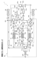
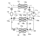
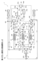
- FIG. 1 is a configuration diagram of a refrigeration cycle apparatus according to the first embodiment
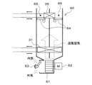
- FIG. 2 is a configuration diagram of an indoor air conditioning unit according to the first embodiment
- FIG. 3 is a block diagram showing the control system of the vehicle air conditioner according to the first embodiment
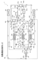
- FIG. 4 is an explanatory diagram showing the operation mode of the multiple chiller cooling mode according to the first embodiment
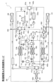
- FIG. 5 is an explanatory diagram showing an operation mode of a multiple chiller battery cooling mode according to the first embodiment
- FIG. 6 is an explanatory diagram showing the operation mode of the multiple chiller waste heat recovery mode according to the first embodiment
- FIG. 1 is a configuration diagram of a refrigeration cycle apparatus according to the first embodiment
- FIG. 2 is a configuration diagram of an indoor air conditioning unit according to the first embodiment
- FIG. 3 is a block diagram showing the control system of the vehicle air conditioner according to the first embodiment
- FIG. 4 is an explanatory diagram showing the operation mode of the multiple chiller cooling mode according to the first embodiment
- FIG. 5 is an explanatory diagram showing
- FIG. 7 is an explanatory diagram showing the operation mode of the multiple chiller outside air heat absorption mode according to the first embodiment
- FIG. 8 is an explanatory diagram showing the operation mode of the cooling & battery cooling mode according to the first embodiment.
- FIG. 9 is an explanatory diagram showing the operation mode of the dehumidification heating & waste heat recovery mode according to the first embodiment
- FIG. 10 is an explanatory diagram showing the operation mode of the dehumidification heating & outside air heat absorption mode according to the first embodiment
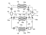
- FIG. 11 is a configuration diagram of a refrigeration cycle apparatus according to the second embodiment
- FIG. 12 is an explanatory diagram showing the first aspect of the multiple chiller circulation mode in the refrigeration cycle according to the second embodiment;
- FIG. 13 is an explanatory diagram showing a second aspect of the multiple chiller circulation mode in the refrigeration cycle according to the second embodiment
- FIG. 14 is an explanatory diagram showing the first aspect of the first chiller circulation mode in the refrigeration cycle according to the second embodiment
- FIG. 15 is an explanatory diagram showing a second aspect of the first chiller circulation mode in the refrigeration cycle according to the second embodiment
- FIG. 16 is an explanatory diagram showing an example of the second chiller circulation mode in the refrigeration cycle according to the second embodiment
- FIG. 17 is an explanatory diagram showing the operation mode of the multiple chiller cooling mode according to the second embodiment
- FIG. 18 is an explanatory diagram showing the operation mode of the cooling & battery cooling mode according to the second embodiment.
- FIG. 19 is an explanatory diagram showing the operation mode of the cooling mode using the second chiller according to the second embodiment
- FIG. 20 is an explanatory diagram showing the operation mode of the dehumidification heating & outside air heat absorption mode according to the second embodiment
- FIG. 21 is an explanatory diagram showing the operation mode of the second chiller use dehumidification heating mode according to the second embodiment
- FIG. 22 is an explanatory diagram showing the operation mode of the dehumidification heating & waste heat recovery mode according to the second embodiment
- FIG. 23 is an explanatory diagram showing the operation mode of the cooling mode using the first chiller according to the second embodiment
- FIG. 24 is an explanatory diagram showing the operation mode of the first chiller use battery cooling mode according to the second embodiment
- FIG. 25 is an explanatory diagram showing the operation mode of the first chiller use waste heat recovery mode according to the second embodiment
- FIG. 26 is an explanatory diagram showing the operation mode of the first chiller use outside air heat absorption mode according to the second embodiment
- FIG. 27 is an explanatory diagram showing the operation mode of the first chiller use dehumidification heating mode according to the second embodiment
- FIG. 28 is a configuration diagram of a refrigeration cycle apparatus according to the third embodiment
- FIG. 29 is an explanatory diagram showing an example of a multiple chiller circulation mode in the refrigeration cycle according to the third embodiment
- FIG. 30 is an explanatory diagram showing an example of the first chiller circulation mode in the refrigeration cycle according to the third embodiment
- FIG. 31 is an explanatory diagram showing the operation mode of the first chiller use battery cooling mode according to the third embodiment
- FIG. 32 is an explanatory diagram showing the operation mode of the first chiller use outside air heat absorption mode according to the third embodiment
- FIG. 33 is an explanatory diagram showing the operation mode of the first chiller use waste heat recovery mode according to the third embodiment
- FIG. 34 is a configuration diagram of a refrigeration cycle apparatus according to the fourth embodiment.
- FIG. A refrigeration cycle apparatus 1 according to the first embodiment is mounted on an electric vehicle, which is a vehicle that obtains driving force for running from an electric motor.
- the refrigeration cycle device 1 air-conditions the interior of the vehicle, which is a space to be air-conditioned. That is, the refrigeration cycle device 1 can also be called an air conditioner with a device temperature control function.
- the battery B is a secondary battery that stores power to be supplied to onboard equipment such as an electric motor, and is, for example, a lithium ion battery.
- Battery B is a so-called assembled battery formed by stacking a plurality of battery cells and electrically connecting these battery cells in series or in parallel.
- the higher the temperature of the battery the more likely the deterioration of the cells constituting the battery progresses.
- the battery B can be cooled by cold heat generated by the refrigerating cycle 10 .
- the electric vehicle according to the first embodiment is equipped with an inverter, a motor generator, a transaxle device, etc., as examples of in-vehicle devices that generate heat during operation.
- An inverter is a power converter that converts direct current to alternating current.
- the motor generator outputs driving force for running when supplied with electric power, and generates regenerative electric power at the time of deceleration or the like.
- a transaxle device is a device that integrates a transmission, a final gear, and a differential gear (differential gear).
- the refrigerating cycle device 1 is configured to recover the waste heat generated in the on-vehicle equipment using the refrigeration cycle 10 in order to effectively utilize the waste heat generated with the operation of these on-vehicle equipment. .
- the refrigeration cycle device 1 has a refrigeration cycle 10, a heat medium circuit 30, an indoor air conditioning unit 60, a control device 70, and the like.
- the refrigeration cycle 10 can cool or heat the heat medium circulating in the heat medium circuit 30 by heat exchange with the refrigerant.
- the refrigerating cycle 10 in the refrigerating cycle device 1 includes, as components, a compressor 11, a heat medium refrigerant heat exchanger 13, a high-stage expansion valve 14, a gas-liquid separator 15, a first expansion valve 17a, and a second expansion valve 17b. , a first chiller 18 , a second chiller 19 and an accumulator 20 .
- the refrigerating cycle 10 employs an HFO-based refrigerant (specifically, R1234yf) as a refrigerant.
- the compressor 11 sucks, compresses, and discharges the refrigerant.
- Compressor 11 is located in the hood of the vehicle.
- the compressor 11 is configured by accommodating two compression mechanisms, a low-stage compression mechanism and a high-stage compression mechanism, and an electric motor for rotationally driving both compression mechanisms in a housing that forms an outer shell thereof. It is That is, the compressor 11 is a two-stage boost electric compressor.
- the housing of the compressor 11 is provided with an intake port 11a, an intermediate pressure port 11b and a discharge port 11c.
- the intake port 11a is an intake port for sucking low-pressure refrigerant from the outside of the housing into the low-stage compression mechanism.
- the discharge port 11c is a discharge port that discharges the high-pressure refrigerant discharged from the high-stage compression mechanism to the outside of the housing.
- the intermediate-pressure port 11b is an intermediate-pressure suction port for allowing intermediate-pressure refrigerant to flow from the outside of the housing to the inside to join the refrigerant in the compression process from low pressure to high pressure. That is, the intermediate pressure port 11b is connected inside the housing to the discharge port side of the low-stage compression mechanism and the suction port side of the high-stage compression mechanism.
- the operation (rotational speed) of the electric motor is controlled by a control signal output from the control device 70, which will be described later. That is, the refrigerant discharge capacity of the compressor 11 is changed by this rotational speed control.
- the refrigerant inlet side of the heat medium refrigerant heat exchanger 13 is connected to the discharge port 11c of the compressor 11 via the first three-way joint 12a.
- the first three-way joint 12a has three inlets and outlets communicating with each other.
- a joint portion formed by joining a plurality of pipes or a joint portion formed by providing a plurality of refrigerant passages in a metal block or a resin block can be adopted.
- the first three-way joint 12 a is a branching portion that branches the flow of refrigerant discharged from the compressor 11 .
- the refrigerant inlet side of the heat medium refrigerant heat exchanger 13 is connected to one outlet of the first three-way joint 12a.
- a bypass passage 21 is connected to the other outflow port of the first three-way joint 12a.
- a bypass side flow control valve 22 is arranged in the bypass passage 21 .
- the bypass-side flow control valve 22 adjusts the discharged refrigerant that has flowed out from the other outlet of the first three-way joint 12a (that is, the other discharged refrigerant branched at the first three-way joint 12a) during a hot gas heating mode, etc., which will be described later. ) is a decompression part on the side of the bypass passage.
- the bypass-side flow rate adjustment valve 22 is a bypass-side flow rate adjustment section that adjusts the flow rate (mass flow rate) of the refrigerant flowing through the bypass passage 21 .
- the bypass side flow control valve 22 is an electric variable throttle mechanism having a valve body that changes the throttle opening and an electric actuator (specifically, a stepping motor) that displaces the valve body.
- the operation of the bypass side flow control valve 22 is controlled by control pulses output from the control device 70 .
- the bypass side flow control valve 22 By fully opening the valve opening, the bypass side flow control valve 22 has a fully open function that functions as a mere refrigerant passage without exerting almost any refrigerant decompression action or flow rate adjustment action. Further, the bypass side flow control valve 22 has a fully closing function of closing the refrigerant passage by fully closing the valve opening degree.
- the heat medium refrigerant heat exchanger 13 has a refrigerant passage 13a through which the high-pressure refrigerant discharged from the compressor 11 flows, and a heat medium passage 13b through which the heat medium circulating in the heat medium circuit 30 flows.
- the heat medium-refrigerant heat exchanger 13 is a condenser that exchanges heat between the high-pressure refrigerant flowing through the refrigerant passage 13a and the heat medium flowing through the heat medium passage 13b to condense. That is, the heat medium-refrigerant heat exchanger 13 radiates the heat of the high-pressure refrigerant discharged from the discharge port 11c of the compressor 11 to the heat medium circulating in the heat medium circuit 30, thereby heating the heat medium.
- the inlet side of the high stage expansion valve 14 is connected to the refrigerant outlet side of the heat medium refrigerant heat exchanger 13 .
- the high-stage expansion valve 14 has a valve element configured to be able to change the throttle opening degree, and an electric actuator composed of a stepping motor for changing the throttle opening degree of the valve body. make up the mechanism.
- the high-stage expansion valve 14 is configured to be settable between a throttled state in which pressure reduction is achieved and a fully open state in which pressure reduction is not exhibited. Therefore, the high pressure side expansion valve 14 can reduce the pressure of the high pressure refrigerant flowing out of the heat medium refrigerant heat exchanger 13 to intermediate pressure refrigerant.
- the operation of the high stage expansion valve 14 is controlled by a control signal output from the control device 70 .
- a refrigerant inlet of the gas-liquid separator 15 is connected to the refrigerant outlet of the high stage expansion valve 14 .
- the gas-liquid separator 15 is a gas-liquid separation unit that separates the gas-liquid two-phase refrigerant that has flowed out of the heat medium refrigerant heat exchanger 13 via the high-stage expansion valve 14 .
- the gas-liquid separator 15 adopts a centrifugal separation method (cyclone separator method) that separates the gas and liquid of the refrigerant by the action of the centrifugal force generated by swirling the refrigerant that has flowed into the inner space of the cylindrical main body. It is
- the internal volume of the gas-liquid separator 15 according to the first embodiment is such that even if the load fluctuation occurs in the cycle and the flow rate of the refrigerant circulating through the cycle fluctuates, surplus refrigerant cannot be substantially stored. Volume.
- One end of the intermediate-pressure refrigerant passage 23 is connected to the gas-phase refrigerant outlet of the gas-liquid separator 15 .
- the other end of the intermediate pressure refrigerant passage 23 is connected to the intermediate pressure port 11 b of the compressor 11 . Therefore, the intermediate-pressure refrigerant passage 23 can guide the gas-phase intermediate-pressure refrigerant separated by the gas-liquid separator 15 to the intermediate-pressure port 11 b of the compressor 11 .
- a check valve (not shown) is arranged in the intermediate pressure refrigerant passage 23 to prevent the refrigerant from flowing back from the compressor 11 side to the gas-liquid separator 15 side.
- the check valve may be arranged between the flow path from the gas-phase refrigerant outlet of the gas-liquid separator 15 to the intermediate pressure port 11b of the compressor 11. It may be arranged, or may be arranged at the gas-phase refrigerant outlet of the gas-liquid separator 15 .
- the liquid-phase refrigerant outlet of the gas-liquid separator 15 is connected to the refrigerant branch portion 16a via a fixed throttle (not shown).
- the fixed throttle is composed of a nozzle, an orifice, a capillary tube, etc. with a fixed throttle opening, and decompresses the liquid-phase refrigerant separated by the gas-liquid separator 15 .
- a fixed orifice such as a nozzle or orifice
- the area of the throttle passage rapidly shrinks or expands.
- the dryness of the refrigerant on the upstream side of the fixed throttle can be self-adjusted (balanced).
- the refrigerant branch portion 16a is formed in a three-way joint shape having three inlets and outlets communicating with each other. That is, the refrigerant branching part 16a has one refrigerant inlet and a plurality of refrigerant outlets, and branches the flow of the refrigerant flowing out from the liquid-phase refrigerant outlet side of the gas-liquid separator 15 into a plurality of flows. .
- the refrigerant branch portion 16a has two refrigerant outlets.
- a first expansion valve 17a, a first chiller 18, and an accumulator 20 are connected to one of the refrigerant outlets of the refrigerant branch portion 16a, and a second expansion valve 17b and a second chiller 19 are connected to the other refrigerant outlet. is connected. Therefore, the refrigerant branching part 16a branches the refrigerant flow that has flowed out from the gas-liquid separator 15 side into a refrigerant flow on the first chiller 18 side and a refrigerant flow on the second chiller 19 side.
- the first expansion valve 17a has a valve element configured to be able to change the opening degree of the throttle, and an electric actuator that changes the opening degree of the valve element, and is configured as an electric variable throttle mechanism.
- the first expansion valve 17a exhibits a throttling function that achieves an arbitrary refrigerant decompression action by setting the valve opening degree to an intermediate opening degree.
- the first expansion valve 17a has a fully open function in which the valve opening degree is fully opened so that the valve opening degree is fully closed, and the valve opening degree is fully closed. It has a fully closed function to block the refrigerant passage.
- the operation of the first expansion valve 17 a is controlled by a control signal (control pulse) output from the control device 70 .
- the first expansion valve 17a can reduce the pressure of the refrigerant that has flowed in from one of the refrigerant outlets of the refrigerant branch portion 16a until it becomes a low-pressure refrigerant, and allows the refrigerant to flow out.
- the first expansion valve 17a can adjust the flow rate of refrigerant flowing out of one of the refrigerant outlets of the refrigerant branch portion 16a, it is possible to relatively adjust the flow rate of refrigerant flowing out of the other refrigerant outlet. .
- the refrigerant inlet side of the first chiller 18 is connected to the refrigerant outlet of the first expansion valve 17a.
- the first chiller 18 includes a refrigerant passage 18a through which the low-pressure refrigerant decompressed by the first expansion valve 17a flows, and a heat medium passage 18b through which the heat medium circulating in the heat medium circuit 30 flows.
- the first chiller 18 is an evaporator that exchanges heat between the low-pressure refrigerant flowing through the refrigerant passage 18a and the heat medium flowing through the heat medium passage 18b to evaporate the low-pressure refrigerant and exhibit heat absorption.
- An accumulator 20 is connected to the outlet side of the refrigerant passage 18a in the first chiller 18 via a second three-way joint 12b. As shown in FIG. 1, one of the refrigerant inlets of the second three-way joint 12b is connected to the refrigerant outlet side of the first chiller 18, and the other of the refrigerant inlets of the second three-way joint 12b is connected to a bypass passage. 21 is connected.
- a refrigerant inlet of the accumulator 20 is connected to the refrigerant outlet of the second three-way joint 12b.
- the accumulator 20 is a gas-liquid separation unit that separates the liquid-phase refrigerant and the gas-phase refrigerant of the outlet refrigerant in the first chiller 18 and stores surplus refrigerant in the cycle.
- the outlet side of the accumulator 20 is connected to a refrigerant junction 16b formed in the shape of a three-way joint.
- the second expansion valve 17b is connected to the other refrigerant outlet of the refrigerant branch portion 16a.
- the second expansion valve 17b has a valve element configured to change the degree of throttle opening and an electric actuator that changes the degree of opening of the valve element. It is configured as a variable diaphragm mechanism.
- the second expansion valve 17b can exhibit the throttling function, the fully open function, and the fully closed function by appropriately adjusting the valve opening degree from the fully open state to the fully closed state. can.
- the operation of the second expansion valve 17 b is controlled by a control signal (control pulse) output from the control device 70 .
- the second expansion valve 17b can reduce the pressure of the refrigerant that has flowed in from the other side of the refrigerant outlet port of the refrigerant branch portion 16a until it becomes a low-pressure refrigerant and allows the second expansion valve 17b to flow out.
- the second expansion valve 17b can adjust the flow rate of refrigerant flowing from the other of the refrigerant outlets of the refrigerant branch portion 16a, it is possible to relatively adjust the flow rate of refrigerant flowing toward the first chiller 18 side. .
- the refrigerant inlet side of the second chiller 19 is connected to the refrigerant outlet of the second expansion valve 17b.
- the second chiller 19 has a refrigerant passage 19a through which the low-pressure refrigerant decompressed by the second expansion valve 17b flows, and a heat medium passage 19b through which the heat medium circulating in the heat medium circuit 30 flows.
- the second chiller 19 is an evaporator that exchanges heat between the low-pressure refrigerant flowing through the refrigerant passage 19a and the heat medium flowing through the heat medium passage 19b to evaporate the low-pressure refrigerant and exhibit heat absorption.
- a refrigerant junction 16 b is connected to the outlet side of the refrigerant passage 19 a in the second chiller 19 .
- the refrigerant merging portion 16b has a plurality of refrigerant inlets and one refrigerant outlet, and merges a plurality of refrigerant flows branched by the refrigerant branching portion 16a. As shown in FIG. 1, the refrigerant junction 16b has two refrigerant inlets. One of the refrigerant inlets of the refrigerant merging portion 16 b is connected to the refrigerant outlet side of the accumulator 20 , and the other is connected to the refrigerant outlet side of the second chiller 19 .
- the refrigerant merging section 16b merges the refrigerant flow that has passed through the first chiller 18 side and the refrigerant flow that has passed through the second chiller 19 side into one refrigerant flow and causes it to flow out.
- the suction port side of the compressor 11 is connected to the refrigerant outlet of the refrigerant junction 16b.
- the refrigerant in the process of increasing pressure sucked from the suction port 11a of the compressor 11 is converted into a gas phase through the high-stage expansion valve 14 and the gas-liquid separator 15.
- Intermediate pressure refrigerant can be merged via intermediate pressure port 11b. That is, the refrigerating cycle 10 can constitute a gas injection cycle.
- the compression efficiency of the high-stage compression mechanism can be improved by causing the low-temperature mixed refrigerant to be sucked into the high-stage compression mechanism. Furthermore, the pressure difference between the suction refrigerant pressure and the discharge refrigerant pressure of both the low-stage compression mechanism and the high-stage compression mechanism can be reduced to improve the compression efficiency of both compression mechanisms. As a result, the COP of the refrigeration cycle 10 as a whole can be improved.
- the heat medium circuit 30 is a heat medium circulation circuit in which a heat medium temperature-controlled by the refrigeration cycle 10 or the like circulates.
- a heat medium ethylene glycol, dimethylpolysiloxane, a solution containing a nanofluid or the like, an antifreeze liquid, or the like can be used.
- the heat medium circuit 30 includes a cooler core 31, a battery heat exchange section 32, an equipment heat exchange section 33, an outside air heat exchanger 34, a heater core 35, an electric heater 36, first pumps 37 to fourth It is configured by connecting pumps 40 and the like by heat medium flow paths.
- the outlet side of the first pump 37 is connected to the inlet side of the heat medium passage 18b of the first chiller 18.
- the first pump 37 is a heat medium pump that sucks and discharges the heat medium flowing through the heat medium circuit 30, and may be an electric water pump, for example.
- the first pump 37 pumps the heat medium toward the inlet side of the heat medium passage 18 b in the first chiller 18 .
- the outlet side of the second pump 38 is connected to the inlet side of the heat medium passage 19b of the second chiller 19 .
- the second pump 38 is a heat medium pump that sucks and discharges a heat medium, like the first pump 37 , and pressure-feeds the heat medium toward the inlet side of the heat medium passage 19 b in the second chiller 19 .
- a first connecting portion 45 a is connected to the outlet side of the heat medium passage 19 b of the second chiller 19 .
- the first connecting portion 45a is formed in the shape of a three-way joint having three inlets and outlets communicating with each other.
- a joint member formed by joining a plurality of pipes or a joint member formed by providing a plurality of refrigerant passages in a metal block or a resin block can be used as the first connection portion 45a.
- the heat medium circuit 30 has a plurality of connection portions formed in the same manner as the first connection portion 45a. Specifically, the heat medium circuit 30 is provided with a first connection portion 45a to a ninth connection portion 45i, each of which is formed in the shape of a three-way joint.
- the heat medium outlet of the heat medium passage 19b of the second chiller 19 is connected to one of the inlet and outlet ports of the first connection portion 45a.
- One inlet/outlet of the second connection portion 45b is connected to the other inlet/outlet of the first connection portion 45a.
- the heat medium inlet side of the cooler core 31 is connected to another inlet/outlet of the first connection portion 45a.
- the cooler core 31 is a cooling heat exchange unit that exchanges heat between the heat medium flowing through the heat medium circuit 30 and the blown air supplied into the vehicle interior, which is the space to be air-conditioned, to cool the blown air.
- the cooler core 31 is arranged inside an indoor air conditioning unit 60, which will be described later, and causes the heat medium to absorb heat from the air blown into the passenger compartment. Therefore, the cooler core 31 corresponds to an example of a cooling unit that cools the blown air.
- a third inlet/outlet 44 c of the four-way valve 44 is connected to the heat medium outlet side of the cooler core 31 .
- One of the inlets and outlets of the second connecting portion 45b is connected to the outlet side of the heat medium passage 18b in the first chiller 18.
- the other inlet/outlet of the second connection portion 45b is connected to the other inlet/outlet of the first connection portion 45a, and the other inlet/outlet of the second connection portion 45b is connected to the first
- the third inlet/outlet 41c of the five-way valve 41 is connected.
- the first five-way valve 41 is a flow control valve having a first inlet/outlet 41a to a fifth inlet/outlet 41e.
- the first five-way valve 41 can allow the heat medium that has flowed in from any one of the first inlet/outlet 41a to the fifth inlet/outlet 41e to flow out from any of the remaining inlets/outlets. Therefore, the first five-way valve 41 corresponds to a part of the switching section.
- the first five-way valve 41 can be formed, for example, by combining a plurality of flow control valves such as three-way flow control valves.
- the outlet side of the heat medium passage 13b in the heat medium refrigerant heat exchanger 13 is connected to the first inlet/outlet 41a of the first five-way valve 41, and the second inlet/outlet 41b of the first five-way valve 41 is connected to: One of the inlets and outlets of the third connecting portion 45c is connected.
- the fourth inlet/outlet 41d of the first five-way valve 41 is connected to the heat medium inlet side of the outside air heat exchanger 34, and the fifth inlet/outlet 41e of the first five-way valve 41 is connected to the electric heater 36. is connected to the heat medium inlet side.
- the heat medium refrigerant heat exchanger 13 is a condenser that condenses the refrigerant by heat exchange between the high-pressure refrigerant and the heat medium in the refrigeration cycle 10, and has the refrigerant passage 13a and the heat medium passage 13b. ing.
- a fourth pump 40 is connected to the inlet side of the heat medium refrigerant heat exchanger 13 .
- the fourth pump 40 is a heat medium pump that sucks and discharges the heat medium that has flowed through the seventh connection portion 45g, and can adopt the same configuration as the first pump 37 and the like.
- the inlet side of the heat medium passage 13b of the heat medium refrigerant heat exchanger 13 is connected to the discharge port of the fourth pump 40 . Therefore, the fourth pump 40 pressure-feeds the heat medium toward the first inlet/outlet 41a side of the first five-way valve 41 through the heat medium passage 13b of the heat medium/refrigerant heat exchanger 13 .
- the second inlet/outlet 41b of the first five-way valve 41 is connected to one of the inlet/outlets of the third connecting portion 45c.
- the heat medium inlet side of the battery heat exchange portion 32 is connected to the other one of the inlets and outlets of the third connection portion 45c, and the other inlet and outlet of the third connection portion 45c is connected to the third five-way A third inlet/outlet 43c of the valve 43 is connected.
- the battery heat exchange section 32 is a heat exchange section for adjusting the temperature of the battery B by exchanging heat between the heat medium flowing through the third connection section 45c and the battery cells that constitute the battery B.
- the battery heat exchange unit 32 is an example of a cooling unit in which the battery B is the object to be cooled.
- a heat medium passage is formed inside the battery heat exchange section 32 in which a plurality of passages are connected in parallel.
- the heat medium passage of the battery heat exchange portion 32 is formed so as to be able to absorb the waste heat of the battery B from the entire area of the battery B evenly.
- the heat medium passage of the battery heat exchange section 32 is formed so as to uniformly absorb the heat of all the battery cells and to cool all the battery cells equally.
- the battery heat exchange section 32 may be formed by arranging heat medium passages between the stacked battery cells. Also, the battery heat exchange portion 32 may be formed integrally with the battery B. As shown in FIG. For example, the heat medium passage may be formed integrally with the battery B by providing a heat medium passage in a special case that accommodates the stacked battery cells.
- One of the inflow/outlet ports of the fourth connection portion 45d is connected to the heat medium outlet side of the battery heat exchange portion 32 .
- the fifth inflow/outlet 42e of the second five-way valve 42 is connected to another inflow/outlet in the fourth connection portion 45d, and the third five-way valve is connected to another inflow/outlet in the fourth connection portion 45d.
- 43 is connected to the first inlet/outlet 43a.
- the outside air heat exchanger 34 is a heat exchanger that exchanges heat between the heat medium flowing out from the fourth inlet/outlet 41d of the first five-way valve 41 and the outside air outside the passenger compartment.
- the outside air heat exchanger 34 functions as a heat absorber that absorbs the heat of the outside air into the heat medium when the temperature of the heat medium is lower than the outside air temperature, and when the temperature of the heat medium is higher than the outside air temperature, It functions as a radiator that dissipates the heat of the heat medium to the outside air. Therefore, the outside air heat exchanger 34 corresponds to an example of a cooling unit that cools outside air.
- the heat medium outlet of the outside air heat exchanger 34 is connected to one of the inlets and outlets of the eighth connection portion 45h.
- Another inflow/outlet in the eighth connection portion 45h is connected to one inflow/outlet in the sixth connection portion 45f, and another inflow/outlet in the eighth connection portion 45h is connected to the inflow/outlet of the ninth connection portion 45i.
- One of the outlets is connected.
- a heat medium inlet side of the electric heater 36 is connected to the fifth inlet/outlet 41 e of the first five-way valve 41 .
- the electric heater 36 has a heat medium passage through which the heat medium flowing out from the fifth inlet/outlet 41e of the first five-way valve 41 flows, and is a heating portion that heats the heat medium passing through the heat medium passage.
- a PTC heater having a PTC element that generates heat when supplied with power is employed as the electric heater 36.
- the amount of heat generated by the electric heater 36 is controlled by a control voltage output from the controller 70 .
- the heating medium inlet side of the heater core 35 is connected to the heating medium outlet side of the electric heater 36 .
- the heater core 35 is arranged in the indoor air conditioning unit 60 as shown in FIG. 2, and is a heating heat exchange section that exchanges heat between the heat medium flowing out from the electric heater 36 and the blown air supplied into the passenger compartment.
- the heater core 35 radiates the heat of the heat medium to the blown air to heat the blown air.
- a heat medium outlet of the heater core 35 is connected to one of the inlets and outlets of the ninth connection portion 45i.
- the second five-way valve 42 is a flow control valve having first to fifth inflow/outlet 42a to fifth inflow/outlet 42e, and is configured similarly to the first five-way valve 41. As shown in FIG.
- the second five-way valve 42 can allow the heat medium that has flowed in from any one of the first inflow/outlet 42a to the fifth inflow/outlet 42e to flow out from any of the remaining inflow/outlets. Therefore, the second five-way valve 42 corresponds to part of the switching section.
- the first inlet/outlet 42a of the second five-way valve 42 is connected to one of the inlet/outlets of the seventh connecting portion 45g, and the second inlet/outlet 42b of the second five-way valve 42 is connected to the sixth connecting portion.
- One of the inlets and outlets at 45f is connected.
- the third inlet/outlet 42c of the second five-way valve 42 is connected to the outlet side of the heat medium passage 33a in the equipment heat exchange section 33, and the fourth inlet/outlet 42d of the second five-way valve 42 is connected to the One of the inflow/outlet in the 5 connection part 45e is connected.
- the fourth inflow/outlet 43d of the third five-way valve 43 is connected to another inflow/outlet of the seventh connection portion 45g, and the other inflow/outlet of the seventh connection portion 45g is connected to the fourth inflow/outlet.
- the suction port side of the pump 40 is connected.
- One of the inlets and outlets of the sixth connection portion 45f is connected to one of the inlets and outlets of the eighth connection portion 45h, and the other inlet and outlet of the sixth connection portion 45f is connected to the four-way valve 44.
- a second inlet/outlet 44b is connected.
- the device heat exchange unit 33 is a heat exchange unit that is mounted on an electric vehicle and exchanges heat between the on-vehicle device that generates heat as it operates and the heat medium pressure-fed by the third pump 39 .
- the in-vehicle equipment in the first embodiment may include an inverter, a motor generator, a transaxle device, and the like.
- the equipment heat exchange unit 33 forms a heat medium passage through which the heat medium flowing out from the third pump 39 flows, in a housing or case forming the outer shell of the in-vehicle equipment such as an inverter, a motor generator, a transaxle device, or the like. It consists of
- the device heat exchange unit 33 corresponds to an example of a cooling unit whose object to be cooled is an in-vehicle device.
- a heat medium inlet side of the equipment heat exchange section 33 is connected to a discharge port side of the third pump 39 .
- the third pump 39 is a heat medium pump that sucks and discharges the heat medium that has flowed through the fifth connection portion 45e, and can adopt the same configuration as the first pump 37 and the like.
- a discharge port of the third pump 39 is connected to a heat medium inlet side of the equipment heat exchange section 33 . Therefore, the third pump 39 pressure-feeds the heat medium toward the heat medium inlet side of the equipment heat exchange section 33 .
- the suction port side of the third pump 39 is connected to another one of the inlets and outlets of the fifth connection portion 45e, and the other inlet and outlet of the fifth connection portion 45e is connected to the third five-way valve 43.
- a second inlet/outlet 43b is connected.
- the third five-way valve 43 is a flow regulating valve having first to fifth inlets/outlets 43a to 43e, and is configured similarly to the first five-way valve 41 and the like.
- the third five-way valve 43 can allow the heat medium that has flowed in from any one of the first to fifth inlets 43a to 43e to flow out from any of the remaining inlets. Therefore, the third five-way valve 43 corresponds to part of the switching section.
- the first inflow/outlet 43a of the third five-way valve 43 is connected to one of the inflow/outlet of the fourth connecting portion 45d, and the second inflow/outlet 43b of the third five-way valve 43 is connected to the fifth connecting portion.
- One of the inlets and outlets at 45e is connected.
- the third inlet/outlet 43c of the third five-way valve 43 is connected to one of the inlet/outlets of the third connecting portion 45c, and the fourth inlet/outlet 43d of the third five-way valve 43 is connected to the seventh connecting portion.
- One of the inlets and outlets at 45g is connected.
- the fifth inlet/outlet 43e of the third five-way valve 43 is connected to one inlet/outlet of the ninth connecting portion 45i.
- the first inflow/outlet 42a of the second five-way valve 42 is connected to another inflow/outlet of the seventh connection portion 45g, and the other inflow/outlet of the seventh connection portion 45g is connected to the fourth The suction port side of the pump 40 is connected.
- the refrigerant outlet side of the cooler core 31 is connected to the other inlet/outlet of the eighth connection portion 45h, and the other inlet/outlet of the eighth connection portion 45h is connected to the inlet/outlet of the eighth connection portion 45h.
- One of the outlets is connected.
- the second inlet/outlet 44b of the four-way valve 44 is connected to another inlet/outlet of the sixth connection portion 45f.
- the four-way valve 44 is a flow control valve having four heat medium inlets and outlets, ie, a first inlet/outlet 44a to a fourth inlet/outlet 44d.
- the four-way valve 44 adjusts the flow rate of the heat medium flowing out from any one of the first to fourth inlets 44a to 44d. Therefore, the four-way valve 44 corresponds to a part of the switching section.
- the first inlet/outlet 44a of the four-way valve 44 is connected to the suction port side of the first pump 37, and the second inlet/outlet 44b of the four-way valve 44 is connected to one of the inlets/outlets of the sixth connecting portion 45f. ing.
- the heat medium outlet side of the cooler core 31 is connected to the third inlet/outlet 44c of the four-way valve 44, and the suction port side of the second pump 38 is connected to the fourth inlet/outlet 44d of the four-way valve 44. .
- the heat medium circuit 30 configurations corresponding to the four cooling sections of the cooler core 31, the battery heat exchange section 32, the equipment heat exchange section 33, and the outside air heat exchanger 34 are arranged. Therefore, if one of the four cooling units corresponds to the first cooling unit, one of the remaining cooling units corresponds to the second cooling unit. For example, when the cooler core 31 corresponds to the first cooling section, any one of the battery heat exchanging section 32, the equipment heat exchanging section 33, and the outside air heat exchanger 34 corresponds to the second cooling section.
- the indoor air conditioning unit 60 that constitutes the refrigeration cycle device 1 will be described with reference to FIG.
- the indoor air conditioning unit 60 is for blowing out into the passenger compartment the blown air whose temperature has been adjusted by the refrigeration cycle 10 .
- the interior air-conditioning unit 60 is arranged inside the dashboard (instrument panel) at the forefront of the vehicle interior.
- the indoor air conditioning unit 60 accommodates a blower 62, a cooler core 31, a heater core 35, etc. inside an air passage formed in a casing 61 that forms its outer shell.
- the casing 61 forms an air passage for air blown into the passenger compartment.
- the casing 61 is molded from a resin (for example, polypropylene) having a certain degree of elasticity and excellent strength.
- An inside/outside air switching device 63 is arranged on the most upstream side of the blown air flow of the casing 61 .
- the inside/outside air switching device 63 switches and introduces inside air (vehicle interior air) and outside air (vehicle exterior air) into the casing 61 .
- the inside/outside air switching device 63 continuously adjusts the opening areas of the inside air introduction port for introducing inside air into the casing 61 and the outside air introduction port for introducing outside air into the casing 61 by means of the inside/outside air switching door, so that the amount of introduced inside air and the amount of outside air are adjusted. Change the introduction ratio with the introduction air volume.
- the inside/outside air switching door is driven by an electric actuator for inside/outside air switching door. The operation of this electric actuator is controlled by a control signal output from the control device 70 .
- a blower 62 is arranged downstream of the inside/outside air switching device 63 in the blown air flow.
- the blower 62 blows the air sucked through the inside/outside air switching device 63 into the vehicle interior.
- the blower 62 is an electric blower that drives a centrifugal multi-blade fan with an electric motor.
- the blower 62 has its rotation speed (that is, blowing capacity) controlled by a control voltage output from the control device 70 .
- a cooler core 31 and a heater core 35 are arranged in this order with respect to the blown air flow downstream of the blower 62 . That is, the cooler core 31 is arranged upstream of the heater core 35 in the blown air flow.
- a cold air bypass passage 65 is provided in the casing 61 for bypassing the heater core 35 and allowing the blown air after passing through the cooler core 31 to flow.
- An air mix door 64 is arranged downstream of the cooler core 31 in the casing 61 and upstream of the heater core 35 in the air flow.
- the air mix door 64 is an air volume ratio adjustment unit that adjusts the air volume ratio between the volume of the air passing through the heater core 35 side and the volume of the air passing through the cold air bypass passage 65 among the air that has passed through the cooler core 31. be.
- the air mix door 64 is driven by an air mix door electric actuator. The operation of this electric actuator is controlled by a control signal output from the control device 70 .
- a mixing space is arranged downstream of the heater core 35 and the cold air bypass passage 65 in the casing 61 .
- the mixing space is a space in which the blast air heated by the heater core 35 and the unheated blast air passing through the cold air bypass passage 65 are mixed.
- An opening hole for blowing out the blast air mixed in the mixing space (that is, the conditioned air) into the vehicle interior, which is the space to be air-conditioned, is arranged in the downstream portion of the blast air flow of the casing 61 .
- the openings include a face opening, a foot opening, and a defroster opening (all not shown).
- the face opening hole is an opening hole for blowing air conditioning air toward the upper body of the passenger inside the vehicle.
- the foot opening hole is an opening hole for blowing the conditioned air toward the passenger's feet.
- the defroster opening hole is an opening hole for blowing the conditioned air toward the inner surface of the window glass arranged on the front surface of the vehicle.
- face opening hole, foot opening hole, and defroster opening hole are connected to the face outlet, foot outlet, and defroster outlet (none of which are shown) provided in the passenger compartment via ducts that form air passages. )It is connected to the.
- the air mix door 64 adjusts the air volume ratio between the air volume passing through the heater core 35 and the air volume passing through the cold air bypass passage 65, thereby adjusting the temperature of the conditioned air mixed in the mixing space. Then, the temperature of the blown air (air-conditioned air) blown into the passenger compartment from each outlet is adjusted.
- a face door, a foot door, and a defroster door are arranged on the upstream sides of the face opening hole, the foot opening hole, and the defroster opening hole, respectively.
- the face door adjusts the opening area of the face opening hole.
- the foot door adjusts the opening area of the foot opening hole.
- the defroster door adjusts the opening area of the defroster opening hole.
- the face door, foot door, and defroster door constitute an outlet mode switching device that switches the outlet mode.
- These doors are connected to an electric actuator for driving the outlet mode door via a link mechanism or the like, and are rotated in conjunction with each other.
- the operation of this electric actuator is also controlled by a control signal output from the control device 70 .
- the face mode is an air outlet mode in which the face air outlet is fully opened and air is blown out from the face air outlet toward the upper body of the occupant in the passenger compartment.
- the bi-level mode is an outlet mode that opens both the face and foot outlets to blow air toward the upper body and feet of the passengers inside the vehicle.
- the foot mode is an air outlet mode in which the foot air outlet is fully opened and the defroster air outlet is opened by a small degree of opening so that air is mainly blown out from the foot air outlet.
- the passenger can manually operate the blowout mode switch provided on the operation panel 71 to switch to the defroster mode.
- the defroster mode is an outlet mode in which the defroster outlet is fully opened and air is blown from the defroster outlet to the inner surface of the windshield.
- the control device 70 is composed of a well-known microcomputer including CPU, ROM, RAM, etc. and its peripheral circuits.
- the control device 70 performs various calculations and processes based on the air conditioning control program stored in the ROM, and controls the operation of various controlled devices connected to the output side.
- the control device 70 corresponds to an example of a control section.
- the various devices to be controlled include the compressor 11, the high-stage expansion valve 14, the first expansion valve 17a, the second expansion valve 17b, and the bypass-side flow control valve 22. Furthermore, the various devices to be controlled include an electric heater 36, a first pump 37 to a fourth pump 40, a first five-way valve 41, a second five-way valve 42, a third five-way valve 43, a four-way valve 44, and a blower 62. , an inside/outside air switching device 63, an air mix door 64, and the like.
- Control sensors include an inside air temperature sensor 72a, an outside air temperature sensor 72b, a solar radiation sensor 72c, a high pressure sensor 72d, a first chiller temperature sensor 72e, and a second chiller temperature sensor 72f.
- Control sensors include an air-conditioning air temperature sensor 72g, an equipment temperature sensor 72h, and a battery temperature sensor 72i.
- the inside air temperature sensor 72a is an inside air temperature detection unit that detects the inside air temperature Tr, which is the temperature inside the vehicle compartment.
- the outside air temperature sensor 72b is an outside air temperature detection unit that detects the outside air temperature Tam, which is the temperature outside the vehicle compartment.
- the solar radiation sensor 72c is a solar radiation amount detection unit that detects the amount of solar radiation As irradiated into the vehicle interior.
- the high pressure sensor 72d is a high pressure detection unit that detects the high pressure Pd, which is the pressure of the high pressure refrigerant discharged from the compressor 11.
- the first chiller temperature sensor 72e is a coolant temperature detection unit that detects the coolant evaporation temperature in the coolant passage 18a of the first chiller 18 .
- the second chiller temperature sensor 72f is a second chiller-side refrigerant temperature detection unit that detects the refrigerant evaporation temperature in the refrigerant passage 19a of the second chiller 19 .
- the air-conditioning air temperature sensor 72g is an air-conditioning air temperature detection unit that detects the temperature TAV of air blown out from the mixing space into the vehicle interior.
- the device temperature sensor 72h is a device temperature detection unit that detects the temperature of an inverter or the like mounted as a vehicle device.
- the equipment temperature sensor 72h has a plurality of temperature detection units and can detect the equipment temperature of each of the inverter, motor generator, and transaxle device.
- the battery temperature sensor 72i is a battery temperature detection unit that detects a battery temperature TB, which is the temperature of the battery B.
- the battery temperature sensor 72i has a plurality of temperature detection units and detects temperatures at a plurality of locations of the battery B. FIG. Therefore, the control device 70 can also detect the temperature difference between the parts of the battery B.
- FIG. Furthermore, as the battery temperature TB, an average value of detection values of a plurality of temperature sensors is used.
- a plurality of heat medium temperature sensors are connected to the input side of the control device 70 to detect the temperature of the heat medium in the heat medium circuit 30 .
- the multiple heat medium temperature sensors include a first heat medium temperature sensor 73a to a seventh heat medium temperature sensor 73g.
- the first heat medium temperature sensor 73a is arranged at the outlet portion of the heat medium passage 18b in the first chiller 18, and detects the temperature of the heat medium flowing out of the first chiller 18.
- the second heat medium temperature sensor 73b is arranged at the outlet portion of the heat medium passage 19b in the second chiller 19, and detects the temperature of the heat medium flowing out of the second chiller 19. As shown in FIG.
- the third heat medium temperature sensor 73 c is arranged at the inlet portion of the cooler core 31 and detects the temperature of the heat medium passing through the cooler core 31 .
- the fourth heat medium temperature sensor 73d is arranged at the inlet portion of the heat medium passage in the battery heat exchange section 32 and detects the temperature of the heat medium passing through the battery heat exchange section 32 .
- the fifth heat medium temperature sensor 73e is arranged at the inlet portion of the heat medium passage of the equipment heat exchange section 33, and detects the temperature of the heat medium passing through the heat medium passage 33a of the equipment heat exchange section 33. To detect.
- the sixth heat medium temperature sensor 73f is arranged at the inlet portion of the heat medium passage of the outside air heat exchanger 34 and detects the temperature of the heat medium passing through the outside air heat exchanger 34 .
- the seventh heat medium temperature sensor 73g is arranged at the heat medium inlet portion of the heater core 35 and detects the temperature of the heat medium passing through the heater core 35 .
- the refrigeration cycle device 1 controls the refrigeration cycle 10 and the heat medium circuit 30 by referring to the detection results of the first heat medium temperature sensor 73a to the seventh heat medium temperature sensor 73g.
- control device 70 is connected to an operation panel 71 arranged near the instrument panel in the front part of the passenger compartment. Operation signals from various operation switches provided on the operation panel 71 are input to the control device 70 .
- operation switches provided on the operation panel 71 include an auto switch, an air conditioner switch, an air volume setting switch, a temperature setting switch, and the like.
- the auto switch is an operation switch for setting or canceling automatic control operation of the refrigeration cycle 10 .
- the air conditioner switch is an operation switch that requests that the cooler core 31 cool the blown air.
- the air volume setting switch is an operation switch that is operated when manually setting the air volume of the blower 62 .
- the temperature setting switch is an operation switch for setting a target temperature Tset in the passenger compartment.
- the control device 70 of the first embodiment is integrally configured with a control section that controls various control target devices connected to the output side thereof. Therefore, the configuration (that is, hardware and software) that controls the operation of each controlled device constitutes a control unit that controls the operation of each controlled device.
- the configuration that controls the refrigerant discharge capacity (for example, the number of revolutions) of the compressor 11 in the refrigeration cycle 10 corresponds to the compressor control section 70a.
- the amount of pressure reduction (that is, throttle opening) in the high-stage expansion valve 14, the first expansion valve 17a, the second expansion valve 17b, and the bypass-side flow control valve 22 of the refrigeration cycle 10 is controlled.
- the configuration corresponds to the pressure reduction control section 70b.
- the high-stage expansion valve 14 the first expansion valve 17a, the second expansion valve 17b, and the bypass-side flow control valve 22 are controlled to configure a circuit configuration in which the refrigerant circulates in the refrigeration cycle 10.
- the configuration for switching corresponds to the refrigerant circuit switching control section 70c.
- the first pump 37 to the fourth pump 40, the first five-way valve 41, the second five-way valve 42, the third five-way valve 43, and the four-way valve 44 are controlled to open the heat medium circuit.
- the configuration for switching the circulation circuit of the heat medium in 30 corresponds to the heat medium circuit switching control section 70d.
- the operation mode of the refrigeration cycle device 1 is determined by a combination of the operation mode (circuit configuration) of the refrigeration cycle 10 and the operation mode (circuit configuration) of the heat medium circuit 30 .
- the first chiller 18 absorbs heat from the heat medium to the refrigerant, and the heat medium-refrigerant heat exchanger 13 heats the heat.
- An operation mode in which heat is radiated by the medium-refrigerant heat exchanger 13 is included.
- the operation mode of the refrigeration cycle 10 includes an operation mode in which heat is absorbed from the heat medium to the refrigerant in each of the first chiller 18 and the second chiller 19 and heat is released in the heat medium-refrigerant heat exchanger 13. .
- the accumulator 20 is arranged between the outlet side of the refrigerant passage 18a of the first chiller 18 and the refrigerant junction 16b. Therefore, the refrigerating cycle 10 can ensure the cooling performance of the first chiller 18 .
- the outlet side of the first chiller 18 is provided with an accumulator 20 that forms a gas-liquid interface of the saturated refrigerant. :1 is maintained near the saturated gas.
- outlet side refrigerant of the second chiller 19 is merged at the inlet side of the accumulator 20, when the outlet refrigerant of the second chiller 19 is a superheated refrigerant gas, the outlet refrigerant of the first chiller 18 is this superheated refrigerant gas. It balances in the state of wet steam with a dryness that contains enough liquid refrigerant to cancel out the temperature.
- the balance state of the refrigerant at the outlet of the first chiller 18 shifts to the side of wet steam with a predetermined dryness, and the refrigerant heat absorption amount in the first chiller 18, that is, It is assumed that the cooling performance will deteriorate.
- the accumulator 20 is arranged between the outlet of the refrigerant passage 18a of the first chiller 18 and the refrigerant junction 16b.
- a decrease in performance can be suppressed. If the superheated refrigerant gas on the outlet side of the second chiller 19 joins the refrigerant flow on the outlet side of the accumulator 20, the balanced state of the refrigerant on the outlet side of the first chiller 18 will always be in the state of near saturated gas with a dryness of 1. This is because it can be maintained.
- a hot gas heating mode is included as an operation mode of the refrigeration cycle 10 according to the first embodiment.
- the hot gas heating mode is an operation mode for effectively using the heat generated by the work of the compressor 11 to heat the heat medium.
- An example of the hot gas heating mode will be described.
- the control device 70 puts the high-stage expansion valve 14, the first expansion valve 17a, and the bypass-side flow control valve 22 into throttled states, and puts the second expansion valve 17b into a fully closed state. .
- the refrigerant includes the compressor 11, the first three-way joint 12a, the heat medium refrigerant heat exchanger 13, the high-stage expansion valve 14, the gas-liquid separator 15, the first expansion valve 17a, the first The chiller 18, the second three-way joint 12b, the accumulator 20, and the compressor 11 are circulated in this order.
- the refrigerant circulates through the compressor 11, the first three-way joint 12a, the heat medium refrigerant heat exchanger 13, the high stage expansion valve 14, the gas-liquid separator 15, the intermediate pressure refrigerant passage 23, and the compressor 11 in this order.
- the refrigerant circulates through the compressor 11, the first three-way joint 12a, the bypass side flow control valve 22, the second three-way joint 12b, the accumulator 20, and the compressor 11 in this order. That is, in the hot gas heating mode refrigeration cycle, the three refrigerant circulation circuits are switched so that they coexist.
- the state change of the refrigerant in the hot gas heating mode will be explained.
- the flow of discharged refrigerant discharged from the compressor 11 is first branched at the first three-way joint 12a.
- One of the refrigerants branched at the first three-way joint 12a flows into the heat medium refrigerant heat exchanger 13 and is radiated by the heat medium flowing through the heat medium passage 13b. The heat medium is thereby heated.
- the refrigerant that has flowed out of the heat medium refrigerant heat exchanger 13 is isoenthalpically decompressed and expanded until it becomes an intermediate pressure refrigerant by the high-stage expansion valve 14 in the throttled state.
- the intermediate-pressure refrigerant decompressed by the high stage expansion valve 14 is separated into gas and liquid by the gas-liquid separator 15 .
- the gas-phase refrigerant separated by the gas-liquid separator 15 flows through the intermediate-pressure refrigerant passage 23 into the intermediate-pressure port 11b of the compressor 11, and joins the refrigerant discharged from the low-stage compression mechanism of the compressor 11. Then, it is sucked into the high stage side compression mechanism.
- the liquid-phase refrigerant separated by the gas-liquid separator 15 passes through the first It flows into the expansion valve 17a.
- the refrigerant that has flowed into the first expansion valve 17a is isoenthalpically decompressed.
- the relatively low enthalpy refrigerant flowing out of the first expansion valve 17 a flows into the first chiller 18 .
- the heating medium passage 13b of the first chiller 18 is controlled so that the heating medium does not flow. Therefore, the refrigerant that has flowed into the first chiller 18 flows into the other inlet of the second three-way joint 12b without exchanging heat with the heat medium when flowing through the refrigerant passage.
- the other refrigerant branched at the first three-way joint 12 a flows into the bypass passage 21 .
- the flow rate of the refrigerant that has flowed into the bypass passage 21 is adjusted by the bypass side flow control valve 22 and the pressure is reduced.
- the refrigerant with a relatively high enthalpy decompressed by the bypass-side flow control valve 22 flows into one inlet of the second three-way joint 12b.
- the refrigerant flowing out of the bypass side flow control valve 22 and the refrigerant flowing out of the first chiller 18 are mixed at the second three-way joint 12b.
- the refrigerant that has flowed out of the second three-way joint 12 b flows into the accumulator 20 .
- the gas-phase refrigerant separated by the accumulator 20 is sucked into the compressor 11 and compressed again.
- the heat generated by the work of the compressor 11 can be effectively used to heat the heat medium without radiating the heat of the high-pressure refrigerant to the outside air.
- a plurality of evaporators that is, the first chiller 18 and the second chiller 19 are used to blow air, the battery B, and the vehicle-mounted equipment through the heat medium circulating in the heat medium circuit 30.
- an operation mode in which heat is absorbed from a cooling target such as outside air multiple chiller cooling mode, multiple chiller battery cooling mode, multiple chiller waste heat recovery mode, multiple chiller outside air heat absorption mode, cooling & battery cooling mode, dehumidification heating & waste Includes heat recovery mode, dehumidification heating & outside air heat absorption mode.
- the operation mode of the refrigeration cycle 10 is such that heat is absorbed from the heat medium to the refrigerant in each of the first chiller 18 and the second chiller 19, and heat is This is an operation mode in which heat is radiated by the medium-refrigerant heat exchanger 13 .
- the refrigerant in the refrigeration cycle 10 includes the compressor 11, the heat medium refrigerant heat exchanger 13, the high-stage expansion valve 14, the gas-liquid separator 15, the throttled first expansion valve 17a, the first chiller 18, and the accumulator. 20 and the compressor 11 in order to circulate.
- the refrigerant flows through the compressor 11, the heat medium refrigerant heat exchanger 13, the high-stage expansion valve 14, the gas-liquid separator 15, the throttled second expansion valve 17b, the second chiller 19, and the compressor 11 in this order. circulating.
- the multi-chiller cooling mode which is one of the operation modes in which heat is absorbed from an object to be cooled using a plurality of evaporators, will be described with reference to FIG.
- the multiple chiller cooling mode is an operation mode for cooling the passenger compartment with higher performance by utilizing the cooling performance of the first chiller 18 and the second chiller 19 to absorb heat from the air to be cooled. be.
- control device 70 controls the first pump 37 to the fourth pump 40 to exert their respective pumping capabilities. In addition, the control device 70 controls the operation of the first five-way valve 41 to the third five-way valve 43 and the four-way valve 44, and regulates the flow of the heat medium so that the circuit configuration is suitable for the multiple chiller cooling mode. Control.
- the control device 70 controls such that the heat medium flowing in from the first inlet/outlet 41a flows out from the fourth inlet/outlet 41d. At this time, the control device 70 fully closes the second inlet/outlet 41b, the third inlet/outlet 41c, and the fifth inlet/outlet 41e so that the heat medium does not flow into or out of the first five-way valve 41 .
- the control device 70 controls the heat medium flowing in from the third inlet/outlet 42c to flow out from the first inlet/outlet 42a. At this time, the control device 70 fully closes the second inlet/outlet 42b, the fourth inlet/outlet 42d, and the fifth inlet/outlet 42e so that the heat medium does not flow into or out of the second five-way valve 42 .
- the control device 70 controls such that the heat medium flowing in from the fifth inlet/outlet 43e flows out from the second inlet/outlet 43b. At this time, the controller 70 fully closes the first inflow/outlet 43a, the third inflow/outlet 43c, and the fourth inflow/outlet 43d so that the heat medium does not flow into or out of the third five-way valve 43 .
- the control device 70 controls such that the heat medium flowing in from the third inlet/outlet 44c flows out from the first inlet/outlet 44a and the fourth inlet/outlet 44d.
- the flow rate ratio of the heat medium flowing out from the first inlet/outlet 44a and the heat medium flowing out from the fourth inlet/outlet 44d is determined according to the cooling capacities of the first chiller 18 and the second chiller 19. For example, the refrigeration cycle 10 It is determined so as to maximize the cooling capacity as a whole. Then, the control device 70 fully closes the second inlet/outlet 44 b so that the heat medium does not flow into or out of the four-way valve 44 .
- the heat medium is the first pump 37, the first chiller 18, the second connection portion 45b, the first connection portion 45a, the cooler core 31, the four-way valve 44, the first pump It flows and circulates in the order of 37.
- the heat medium flows and circulates through the second pump 38, the second chiller 19, the first connecting portion 45a, the cooler core 31, the four-way valve 44, and the second pump 38 in this order.
- a heat medium circulation circuit is configured in which the first chiller 18 and the second chiller 19 are connected in parallel to the cooler core 31 . Therefore, in the multiple chiller cooling mode, the blown air can be cooled with a higher cooling capacity than when either the first chiller 18 or the second chiller 19 is used, and the comfort of the passenger compartment can be quickly improved by cooling. can be enhanced.
- the heat medium is the fourth pump 40, the heat medium refrigerant heat exchanger 13, the first five-way valve 41, the outside air heat exchanger 34, the eighth connection portion 45h, the ninth connection portion 45i, It flows in the order of the third five-way valve 43 . Then, when the heat medium flows out from the third five-way valve 43, the fifth connection portion 45e, the third pump 39, the equipment heat exchange portion 33, the second five-way valve 42, the seventh connection portion 45g, the fourth pump It flows in order of 40.
- a heat medium circulation circuit is configured in which the heat medium that has passed through the heat medium refrigerant heat exchanger 13 and the equipment heat exchange unit 33 circulates through the outside air heat exchanger 34. be. Therefore, according to the multi-chiller cooling mode, the heat pumped up by the refrigerating cycle 10 and the waste heat generated in the in-vehicle equipment can be transported via the heat medium and radiated to the outside air.
- the multiple chiller battery cooling mode utilizes the cooling performance of the first chiller 18 and the second chiller 19 to absorb heat from the battery B to be cooled, thereby cooling the battery B with higher performance.
- the multiple chiller battery cooling mode is effective, for example, when the amount of heat generated by the battery B increases due to rapid charging of the battery B, and the cooling capacity of the first chiller 18 or the second chiller 19 alone is insufficient. .
- control device 70 controls the first pump 37 to the fourth pump 40 to exert their respective pumping capabilities. In addition, the control device 70 controls the operation of the first five-way valve 41 to the third five-way valve 43 and the four-way valve 44 so that the circuit configuration is suitable for the multiple chiller battery cooling mode. to control.
- the control device 70 controls such that the heat medium flowing in from the first inlet/outlet 41a flows out from the fourth inlet/outlet 41d and flows in from the third inlet/outlet 41c.
- the heat medium is controlled to flow out from the second inlet/outlet 41b.
- the control device 70 fully closes the fifth inlet/outlet 41 e so that the heat medium does not flow into or out of the first five-way valve 41 .
- the control device 70 controls the heat medium flowing in from the third inlet/outlet 42c to flow out from the first inlet/outlet 42a, and controls the heat medium flowing in from the fifth inlet/outlet 42e.
- the medium is controlled to flow out from the second inlet/outlet 42b.
- the controller 70 fully closes the fourth inlet/outlet 42d so that the heat medium does not flow into or out of the second five-way valve 42 .
- the control device 70 controls such that the heat medium flowing in from the fifth inlet/outlet 43e flows out from the second inlet/outlet 43b. At this time, the controller 70 fully closes the first inflow/outlet 43a, the third inflow/outlet 43c, and the fourth inflow/outlet 43d so that the heat medium does not flow into or out of the third five-way valve 43 .
- the control device 70 controls such that the heat medium flowing in from the second inlet/outlet 44b flows out from the first inlet/outlet 44a and the fourth inlet/outlet 44d.
- the flow rate ratio of the heat medium flowing out from the first inlet/outlet 44a and the heat medium flowing out from the fourth inlet/outlet 44d is determined according to the cooling capacity of the first chiller 18 and the second chiller 19, for example. Then, the control device 70 fully closes the third inlet/outlet 44 c so that the heat medium does not flow into or out of the four-way valve 44 .
- the heat medium is the first pump 37, the first chiller 18, the second connection portion 45b, the first five-way valve 41, the third connection portion 45c, the battery heat exchange portion 32, the second fifth The flow circulates through the one-way valve 42, the sixth connection portion 45f, the four-way valve 44, and the first pump 37 in this order.
- the heat medium flows through the second pump 38, the second chiller 19, the first connection portion 45a, the second connection portion 45b, the first five-way valve 41, the third connection portion 45c, the battery heat exchange portion 32, the second It flows and circulates through the five-way valve 42, the sixth connection portion 45f, the four-way valve 44, and the second pump 38 in this order.
- a heat medium circulation circuit is configured in which the first chiller 18 and the second chiller 19 are connected in parallel to the battery heat exchange section 32 . Therefore, in the multiple chiller battery cooling mode, the battery B can be cooled with a higher cooling capacity than when either the first chiller 18 or the second chiller 19 is used, and the amount of heat generated increases due to rapid charging and the like. Battery B can be cooled quickly even in such a case.
- the heat medium is the fourth pump 40, the heat medium refrigerant heat exchanger 13, the first five-way valve 41, the outside air heat exchanger 34, the eighth connecting portion 45h, the ninth connecting portion 45i. , the third five-way valve 43 . Then, when the heat medium flows out from the third five-way valve 43, the fifth connection portion 45e, the third pump 39, the equipment heat exchange portion 33, the second five-way valve 42, the seventh connection portion 45g, the fourth pump It flows in order of 40.
- a heat medium circulation circuit is configured in which the heat medium that has passed through the heat medium refrigerant heat exchanger 13 and the equipment heat exchange unit 33 circulates through the outside air heat exchanger 34. be done. Therefore, according to the multiple chiller battery cooling mode, the heat pumped up by the refrigerating cycle 10 and the waste heat generated in the vehicle-mounted equipment can be transported via the heat medium and released to the outside air.
- the multiple chiller waste heat recovery mode utilizes the cooling performance of the first chiller 18 and the second chiller 19 to absorb heat from the onboard equipment to be cooled, thereby recovering the waste heat of the onboard equipment with higher performance. is the operating mode of
- control device 70 controls the first pump 37 to the fourth pump 40 to exhibit the pumping capacity determined for each.
- control device 70 controls the operation of the first five-way valve 41 to the third five-way valve 43 and the four-way valve 44 so that the circuit configuration is suitable for the multiple chiller waste heat recovery mode. control the flow.
- the control device 70 controls the heat medium flowing in from the first inlet/outlet 41a to flow out from the fifth inlet/outlet 41e, and the heat medium from the third inlet/outlet 41c.
- the heat medium is controlled to flow out from the second inlet/outlet 41b.
- the controller 70 fully closes the fourth inlet/outlet 41 d so that the heat medium does not flow into or out of the first five-way valve 41 .
- the control device 70 controls the heat medium flowing in from the third inlet/outlet 42c to flow out from the first inlet/outlet 42a. At this time, the control device 70 fully closes the first inlet/outlet 42a, the fourth inlet/outlet 42d, and the fifth inlet/outlet 42e so that the heat medium does not flow into or out of the second five-way valve 42 .
- the control device 70 controls such that the heat medium flowing in from the fifth inflow/outlet 43e flows out from the fourth inflow/outlet 43d, and the heat medium flowing in from the third inflow/outlet 43c flows out from the fourth inflow/outlet 43d. It is controlled to flow out from the second inflow/outlet 43b. At this time, the control device 70 fully closes the first inlet/outlet 43 a so that the heat medium does not flow into or out of the third five-way valve 43 .
- the control device 70 controls such that the heat medium flowing in from the second inlet/outlet 44b flows out from the first inlet/outlet 44a and the fourth inlet/outlet 44d.
- the flow rate ratio of the heat medium flowing out from the first inlet/outlet 44a and the heat medium flowing out from the fourth inlet/outlet 44d is determined according to the cooling capacity of the first chiller 18 and the second chiller 19, for example. Then, the control device 70 fully closes the third inlet/outlet 44 c so that the heat medium does not flow into or out of the four-way valve 44 .
- the heat medium is the first pump 37, the first chiller 18, the second connection 45b, the first five-way valve 41, the third connection 45c, the third five-way valve 43, the fifth It flows through the connecting portion 45e and the third pump 39 in this order. Then, when the heat medium flows out from the third pump 39, it flows through the equipment heat exchange portion 33, the second five-way valve 42, the sixth connection portion 45f, the four-way valve 44, and the first pump 37 in this order and circulates.
- the heat medium flows through the second pump 38, the second chiller 19, the first connection portion 45a, the second connection portion 45b, the first five-way valve 41, the third connection portion 45c, the third five-way valve 43, the fifth It flows through the connecting portion 45e and the third pump 39 in this order.
- the heat medium flows out from the third pump 39, the heat medium flows through the equipment heat exchange portion 33, the second five-way valve 42, the sixth connection portion 45f, the four-way valve 44, and the second pump 38 in this order and circulates.
- a heat medium circulation circuit is configured in which the first chiller 18 and the second chiller 19 are connected in parallel to the equipment heat exchange section 33 . Therefore, in the multi-chiller waste heat recovery mode, the waste heat of the vehicle-mounted equipment can be recovered with a higher cooling capacity than when either the first chiller 18 or the second chiller 19 is used.
- the heat medium is the fourth pump 40, the heat medium refrigerant heat exchanger 13, the first five-way valve 41, the electric heater 36, the heater core 35, the ninth connecting portion 45i, the third fifth The flow circulates through the direction valve 43, the seventh connecting portion 45g, and the fourth pump 40 in this order.
- a heat medium circulation circuit is configured in which the heat medium that has passed through the heat medium refrigerant heat exchanger 13 and the electric heater 36 circulates through the heater core 35 . Therefore, according to the multiple chiller waste heat recovery mode, the heat pumped up by the refrigeration cycle 10 and the heat applied by the electric heater 36 can be used to heat the blast air. In this case, since the heat pumped up by the refrigeration cycle 10 also includes the waste heat of the on-vehicle equipment recovered by the equipment heat exchange unit 33, the waste heat of the on-vehicle equipment is used to heat the vehicle interior. It can be performed.
- the multiple chiller outside air heat absorption mode utilizes the cooling performance of the first chiller 18 and the second chiller 19 to absorb heat from the outside air, which is the object of cooling, so that the heat absorbed from the outside air is effectively used with higher performance. is the operating mode of
- the control device 70 controls the first pump 37, the second pump 38, and the fourth pump 40 to exert their predetermined pumping capabilities. Note that the control device 70 stops the third pump 39 . In addition, the control device 70 controls the operation of the first five-way valve 41, the third five-way valve 43, and the four-way valve 44 so that the circuit configuration is suitable for the multiple chiller outside air heat absorption mode. to control.
- the control device 70 controls the heat medium flowing in from the first inlet/outlet 41a to flow out from the fifth inlet/outlet 41e, and the heat medium from the third inlet/outlet 41c.
- the heat medium is controlled to flow out from the fourth inlet/outlet 41d.
- the control device 70 fully closes the second inlet/outlet 41 b so that the heat medium does not flow into or out of the first five-way valve 41 .
- the control device 70 controls the heat medium flowing in from the fifth inlet/outlet 43e to flow out from the fourth inlet/outlet 43d. At this time, the control device 70 fully closes the first inlet/outlet 43a, the second inlet/outlet 43b, and the third inlet/outlet 43c so that the heat medium does not flow into or out of the third five-way valve 43 .
- the control device 70 controls the heat medium flowing in from the second inlet/outlet 44b to flow out from the first inlet/outlet 44a and the fourth inlet/outlet 44d.
- the flow rate ratio of the heat medium flowing out from the first inlet/outlet 44a and the heat medium flowing out from the fourth inlet/outlet 44d is determined according to the cooling capacity of the first chiller 18 and the second chiller 19, for example. Then, the control device 70 fully closes the third inlet/outlet 44 c so that the heat medium does not flow into or out of the four-way valve 44 .
- the heat medium is the first pump 37, the first chiller 18, the second connection part 45b, the first five-way valve 41, the outside air heat exchanger 34, the eighth connection part 45h, and the sixth connection part. 45f, the four-way valve 44, and the first pump 37 in order to circulate.
- the heat medium flows through the second pump 38, the second chiller 19, the first connection portion 45a, the second connection portion 45b, the first five-way valve 41, the outside air heat exchanger 34, the eighth connection portion 45h, the sixth connection It flows and circulates through the portion 45f, the four-way valve 44, and the second pump 38 in this order.
- a heat medium circulation circuit is configured in which the first chiller 18 and the second chiller 19 are connected in parallel to the outside air heat exchanger 34 . Therefore, in the multi-chiller outside air heat absorption mode, the outside air heat exchanger 34 performs heat exchange between the heat medium cooled with a higher cooling capacity than when either the first chiller 18 or the second chiller 19 is used, and the outside air. Since it is performed at , the outside air can be effectively used as a heat source.
- the heat medium is the fourth pump 40, the heat medium refrigerant heat exchanger 13, the first five-way valve 41, the electric heater 36, the heater core 35, the ninth connecting portion 45i, the third fifth The flow circulates through the direction valve 43, the seventh connecting portion 45g, and the fourth pump 40 in this order.
- a heat medium circulation circuit is configured in which the heat medium that has passed through the heat medium refrigerant heat exchanger 13 and the electric heater 36 circulates through the heater core 35 . Therefore, according to the multiple chiller outside air heat absorption mode, the heat pumped up by the refrigeration cycle 10 and the heat applied by the electric heater 36 can be used to heat the blast air.
- the heat pumped up by the refrigerating cycle 10 includes the heat absorbed from the outside air by the outside air heat exchanger 34, so that the inside of the vehicle can be heated using the outside air as a heat source.
- the multiple chiller cooling mode, the multiple chiller battery cooling mode, the multiple chiller waste heat recovery mode, and the multiple chiller outside air heat absorption mode correspond to examples of the first cooling mode and the second cooling mode in the present disclosure.
- the multiple chiller cooling mode is the first cooling mode
- the multiple chiller battery cooling mode, the multiple chiller waste heat recovery mode, and the multiple chiller outside air heat absorption mode correspond to the second cooling mode.
- the blowing air, the battery B, the vehicle-mounted equipment, and the outside air which are the cooling targets in the multiple chiller cooling mode, the multiple chiller battery cooling mode, the multiple chiller waste heat recovery mode, and the multiple chiller outside air heat absorption mode, are the first cooling targets in the present disclosure, It corresponds to an example of the second object to be cooled. That is, if one of the blown air, the battery B, the vehicle-mounted device, and the outside air is taken as the first object to be cooled, any one of the remaining objects to be cooled corresponds to the second object to be cooled.
- the cooling performance of the plurality of evaporators is combined into one object to be cooled, such as the multiple chiller cooling mode described above.
- Other operation modes are included in addition to the concentrated operation mode.
- an operation mode for absorbing heat from a cooling object using multiple evaporators there is an operation mode for cooling by allocating the cooling performance of multiple evaporators to multiple cooling objects.
- An operation mode in which the cooling performance of a plurality of evaporators is allocated to a plurality of objects to be cooled, respectively, will be described below with reference to the drawings.
- the cooling & battery cooling mode will be described with reference to FIG.
- the cooling performance of the first chiller 18 and the second chiller 19 is allocated to the battery B and the air to be cooled, respectively, and the cooling of the passenger compartment and the cooling of the battery B are performed in parallel. mode.
- control device 70 controls the first to fourth pumps 37 to 40 to exert their respective pumping capabilities. In addition, the control device 70 controls the operation of the first five-way valve 41 to the third five-way valve 43 and the four-way valve 44 so that the circuit configuration is suitable for the cooling & battery cooling mode. to control.
- the control device 70 controls such that the heat medium flowing in from the first inlet/outlet 41a flows out from the fourth inlet/outlet 41d and flows in from the third inlet/outlet 41c.
- the heat medium is controlled to flow out from the second inlet/outlet 41b.
- the control device 70 fully closes the fifth inlet/outlet 41 e so that the heat medium does not flow into or out of the first five-way valve 41 .
- the control device 70 controls the heat medium flowing in from the third inlet/outlet 42c to flow out from the first inlet/outlet 42a, and controls the heat medium flowing in from the fifth inlet/outlet 42e.
- the medium is controlled to flow out from the second inlet/outlet 42b.
- the controller 70 fully closes the fourth inlet/outlet 42d so that the heat medium does not flow into or out of the second five-way valve 42 .
- the control device 70 controls the heat medium flowing in from the fifth inlet/outlet 43e to flow out from the second inlet/outlet 43b. At this time, the controller 70 fully closes the first inflow/outlet 43a, the third inflow/outlet 43c, and the fourth inflow/outlet 43d so that the heat medium does not flow into or out of the third five-way valve 43 .
- control device 70 controls the heat medium flowing in from the second inflow/outlet 44b to flow out from the first inflow/outlet 44a, and controls the heat medium flowing in from the third inflow/outlet 44c to flow out from the third inflow/outlet 44c. 4 Control to flow out from the inflow/outlet 44d.
- the heat medium is the first pump 37, the first chiller 18, the second connection part 45b, the first five-way valve 41, the third connection part 45c, the battery heat exchange part 32, the fourth connection 45d, the second five-way valve 42, the sixth connection portion 45f, the four-way valve 44, and the first pump 37 in this order.
- the heat medium cooled by the first chiller 18 circulates through the battery heat exchange section 32 , so the batteries B can be cooled by the cooling performance of the first chiller 18 .
- the heat medium flows and circulates through the second pump 38, the second chiller 19, the first connecting portion 45a, the cooler core 31, the four-way valve 44, and the second pump 38 in this order.
- the heat medium cooled by the second chiller 19 circulates through the cooler core 31, so that the cooling performance of the second chiller 19 cools the blown air to cool the passenger compartment. can.
- the heat medium is the fourth pump 40, the heat medium refrigerant heat exchanger 13, the first five-way valve 41, the outside air heat exchanger 34, the eighth connection portion 45h, and the ninth connection portion 45i. , the third five-way valve 43 . Then, when the heat medium flows out from the third five-way valve 43, the fifth connection portion 45e, the third pump 39, the equipment heat exchange portion 33, the second five-way valve 42, the seventh connection portion 45g, the fourth pump 40 flows and circulates.
- a heat medium circulation circuit is configured in which the heat medium that has passed through the heat medium refrigerant heat exchanger 13 and the equipment heat exchange unit 33 circulates through the outside air heat exchanger 34. be done. Therefore, in the cooling & battery cooling mode, the heat pumped up by the refrigerating cycle 10 and the waste heat generated in the in-vehicle equipment can be transported through the heat medium and radiated to the outside air.
- the dehumidification heating & waste heat recovery mode will be described with reference to FIG.
- the cooling performance of the first chiller 18 and the second chiller 19 is assigned to the on-vehicle equipment to be cooled and the blowing air, respectively, to dehumidify the vehicle interior and recover waste heat from the on-board equipment. This is a parallel operation mode.
- the control device 70 controls the first pump 37 to the fourth pump 40 to exert their predetermined pumping capabilities. In addition, the control device 70 controls the operation of the first five-way valve 41 to the third five-way valve 43 and the four-way valve 44 so that the circuit configuration is suitable for the dehumidification heating & waste heat recovery mode. to control the flow of
- the control device 70 controls the heat medium flowing in from the first inlet/outlet 41a to flow out from the fifth inlet/outlet 41e, and the heat medium from the third inlet/outlet 41c.
- the heat medium is controlled to flow out from the second inlet/outlet 41b.
- the controller 70 fully closes the fourth inlet/outlet 41 d so that the heat medium does not flow into or out of the first five-way valve 41 .
- the control device 70 controls the heat medium flowing in from the third inlet/outlet 42c to flow out from the second inlet/outlet 42b. At this time, the control device 70 fully closes the first inlet/outlet 42a, the fourth inlet/outlet 42d, and the fifth inlet/outlet 42e so that the heat medium does not flow into or out of the second five-way valve 42 .
- the control device 70 controls the heat medium flowing in from the fifth inlet/outlet 43e to flow out from the fourth inlet/outlet 43d, and the heat medium flowing in from the third inlet/outlet 43c. It is controlled to flow out from the second inflow/outlet 43b. At this time, the control device 70 fully closes the first inlet/outlet 43 a so that the heat medium does not flow into or out of the third five-way valve 43 .
- control device 70 controls the heat medium flowing in from the second inflow/outlet 44b to flow out from the first inflow/outlet 44a, and controls the heat medium flowing in from the third inflow/outlet 44c to flow out from the third inflow/outlet 44c. 4 Control to flow out from the inflow/outlet 44d.
- the heat medium is the first pump 37, the first chiller 18, the second connection portion 45b, the first five-way valve 41, the third connection portion 45c, the third five-way valve 43, the third 5 connecting portion 45e and the third pump 39 in this order. Then, when the heat medium flows out from the third pump 39, it flows through the equipment heat exchange portion 33, the second five-way valve 42, the sixth connection portion 45f, the four-way valve 44, and the first pump 37 in this order and circulates.
- the heat medium cooled by the first chiller 18 circulates through the equipment heat exchange section 33, so that the cooling performance of the first chiller 18 cools the onboard equipment and The waste heat generated in can be recovered.
- the heat medium flows and circulates through the second pump 38, the second chiller 19, the first connecting portion 45a, the cooler core 31, the four-way valve 44, and the second pump 38 in this order.
- the heat medium cooled by the second chiller 19 circulates through the cooler core 31, so that the cooling performance of the second chiller 19 can dehumidify the blown air.
- the heat medium is the fourth pump 40, the heat medium refrigerant heat exchanger 13, the first five-way valve 41, the electric heater 36, the heater core 35, the ninth connection part 45i, the third It flows and circulates through the five-way valve 43, the seventh connecting portion 45g, and the fourth pump 40 in this order.
- a heat medium circulation circuit is configured in which the heat medium that has passed through the heat medium refrigerant heat exchanger 13 and the electric heater 36 circulates through the heater core 35 . Therefore, according to the dehumidification heating & waste heat recovery mode, the heat pumped up by the refrigeration cycle 10 and the heat applied by the electric heater 36 can be used to heat the blast air dehumidified by the cooler core 31 . In this case, since the heat pumped up by the refrigerating cycle 10 also includes the waste heat of the vehicle-mounted equipment recovered by the equipment heat exchange section 33, the waste heat of the vehicle-mounted equipment is used to dehumidify the vehicle interior. Heating can be done.
- the dehumidification heating & outdoor air heat absorption mode will be described with reference to FIG.
- the cooling performance of the first chiller 18 and the second chiller 19 is allocated to the outside air and blowing air that are the cooling objects, respectively, and the operation in which the dehumidification of the passenger compartment and the heat absorption from the outside air are performed in parallel. mode.
- the control device 70 controls the first pump 37, the second pump 38, and the fourth pump 40 to exhibit their predetermined pumping capabilities. Note that the control device 70 stops the third pump 39 . In addition, the control device 70 controls the operation of the first five-way valve 41, the third five-way valve 43, and the four-way valve 44 so that the circuit configuration is suitable for the dehumidification heating & waste heat recovery mode. to control the flow of
- the control device 70 controls the heat medium flowing in from the first inlet/outlet 41a to flow out from the fifth inlet/outlet 41e, and the heat medium from the third inlet/outlet 41c.
- the heat medium is controlled to flow out from the fourth inlet/outlet 41d.
- the control device 70 fully closes the second inlet/outlet 41 b so that the heat medium does not flow into or out of the first five-way valve 41 .
- the control device 70 controls the heat medium flowing in from the fifth inlet/outlet 43e to flow out from the fourth inlet/outlet 43d. At this time, the control device 70 fully closes the first inlet/outlet 43a, the second inlet/outlet 43b, and the third inlet/outlet 43c so that the heat medium does not flow into or out of the third five-way valve 43 .
- control device 70 controls the heat medium flowing in from the second inflow/outlet 44b to flow out from the first inflow/outlet 44a, and controls the heat medium flowing in from the third inflow/outlet 44c to flow out from the third inflow/outlet 44c. 4 Control to flow out from the inflow/outlet 44d.
- the heat medium is the first pump 37, the first chiller 18, the second connection part 45b, the first five-way valve 41, the outside air heat exchanger 34, the eighth connection part 45h, the sixth connection It flows and circulates through the portion 45f, the four-way valve 44, and the first pump 37 in this order.
- the heat medium cooled by the first chiller 18 circulates through the outside air heat exchanger 34 , so that the first chiller 18 can absorb heat from the outside air due to the cooling performance of the first chiller 18 .
- the heat medium flows and circulates through the second pump 38, the second chiller 19, the first connecting portion 45a, the cooler core 31, the four-way valve 44, and the second pump 38 in this order.
- the heat medium cooled by the second chiller 19 circulates through the cooler core 31, so that the cooling performance of the second chiller 19 can dehumidify the blown air.
- the heat medium is the fourth pump 40, the heat medium refrigerant heat exchanger 13, the first five-way valve 41, the electric heater 36, the heater core 35, the ninth connection part 45i, the third fifth
- the flow circulates through the direction valve 43, the seventh connecting portion 45g, and the fourth pump 40 in this order.
- a heat medium circulation circuit is configured in which the heat medium that has passed through the heat medium refrigerant heat exchanger 13 and the electric heater 36 circulates through the heater core 35 . Therefore, according to the dehumidifying heating & outside air heat absorbing mode, the heat pumped up by the refrigerating cycle 10 and the heat applied by the electric heater 36 can be used to heat the blast air dehumidified by the cooler core 31 . In this case, since the heat pumped up by the refrigerating cycle 10 also includes the heat absorbed from the outside air by the outside air heat exchanger 34, the inside of the vehicle can be dehumidified and heated using the outside air as a heat source.
- the first chiller 18 cools one object to be cooled
- the second chiller 19 cools another object. is cooling the object to be cooled. That is, the cooling & battery cooling mode, the dehumidifying heating & waste heat recovery mode, and the dehumidifying heating & outside air heat absorption mode each correspond to an example of the combined mode.
- the refrigeration cycle device 1 there are multiple chiller cooling modes, cooling & battery cooling modes, and the like as operation modes for cooling the blown air blown into the vehicle interior.
- the cooling performance of the first chiller 18 and the second chiller 19 is used to cool the blown air
- the cooling & battery cooling mode either the first chiller 18 or the second chiller 19
- the cooling performance of is used to cool the blast air.
- the cooling performance used for cooling the blast air which is the object to be cooled, can be adjusted to the evaporator. It can be adjusted in units.
- switching to the multiple chiller cooling mode allows the required It is possible to ensure a cooling performance that is suitable for the vehicle, and to improve the comfort of the vehicle interior.
- the refrigeration cycle device 1 as operation modes for cooling the battery B, it has a multiple chiller battery cooling mode, a cooling & battery cooling mode, and the like.
- the multiple chiller battery cooling mode the battery B is cooled using the cooling performance of the first chiller 18 and the second chiller 19, and in the cooling & battery cooling mode, either the first chiller 18 or the second chiller 19 Cooling of the battery B is performed by utilizing one of the cooling performances.
- the cooling performance used for cooling the battery B to be cooled can be adjusted for each evaporator by selectively using the multiple chiller battery cooling mode, the cooling & battery cooling mode, and the like. .
- the cooling performance of a single evaporator for example, the second chiller 19
- the required cooling performance can be secured. For example, even if the amount of heat generated by the battery B increases due to rapid charging or the like, the refrigeration cycle device 1 can cool the battery B and adjust it to an appropriate temperature range by switching to the multiple chiller battery cooling mode.
- the refrigeration cycle device 1 there are multiple chiller waste heat recovery mode and dehumidification heating & waste heat recovery mode as operation modes for cooling the in-vehicle equipment.
- the cooling performance of the first chiller 18 and the second chiller 19 is used to recover waste heat from onboard equipment.
- the cooling performance of either the first chiller 18 or the second chiller 19 is used to recover waste heat from the vehicle-mounted equipment.
- the cooling performance used for recovering waste heat from the in-vehicle equipment to be cooled can be adjusted for each evaporator. can be adjusted.
- the cooling performance of a single evaporator for example, the first chiller 18
- the required capacity can be secured.
- the refrigeration cycle device 1 there are a multiple chiller outside air heat absorption mode and a dehumidification heating & outside air heat absorption mode as operation modes for cooling the outside air.
- the cooling performance of the first chiller 18 and the second chiller 19 is used to absorb the heat of the outdoor air.
- the cooling performance of either the first chiller 18 or the second chiller 19 is used to absorb the heat of the outside air.
- the cooling performance used for absorbing heat from the outside air, which is the object to be cooled can be adjusted for each evaporator.
- the refrigerating cycle device 1 has the refrigerating cycle 10 and the heat medium circuit 30, and can cool a plurality of objects to be cooled, such as the blown air, the battery B, the in-vehicle equipment, and the outside air. It is configured.
- the refrigerating cycle 10 has a compressor 11 , a heat medium refrigerant heat exchanger 13 , a first expansion valve 17 a , a second expansion valve 17 b , a first chiller 18 and a second chiller 19 .
- the heat medium circuit 30 includes a cooler core 31 as a cooling part for cooling the blown air, a battery heat exchange part 32 as a cooling part for cooling the battery B, and a cooling part for recovering waste heat from the vehicle equipment. It has an equipment heat exchange section 33 as a heat exchanger and an outside air heat exchanger 34 for absorbing heat from the outside air.
- the heat medium circuit 30 heats the heat medium cooled by at least one of the plurality of chillers (the first chiller 18 and the second chiller 19) to a plurality of It is configured to be able to supply to at least one of the cooling units.
- the refrigeration cycle apparatus 1 according to the first embodiment, as shown in FIGS. can be supplied to one of the departments. Therefore, the refrigeration cycle device 1 can cool any one of the blown air, the battery B, the in-vehicle equipment, and the outside air using a plurality of evaporators (the first chiller 18 and the second chiller 19). It is possible to improve the cooling performance for a specific object to be cooled.
- the heat medium circuit 30 includes a cooler core 31, a battery heat exchange section 32, an equipment heat exchange section 33, an outside air heat exchanger 34, and a heat medium flow in the heat medium circuit 30. It has a first five-way valve 41 to a third five-way valve 43 and a four-way valve 44 for switching between.
- the refrigeration cycle device 1 by controlling the operations of the first five-way valve 41 to the third five-way valve 43 and the four-way valve 44, a plurality of operation modes as shown in FIGS. 4 to 10 are realized. can do. That is, the refrigeration cycle device 1 can supply the heat medium cooled by at least one of the plurality of chillers to at least one of the plurality of cooling units.
- the refrigeration cycle apparatus 1 can supply the heat medium cooled by the first chiller 18 and the second chiller 19 to the cooler core 31 by switching to the multiple chiller cooling mode. Thereby, the refrigerating cycle apparatus 1 can cool the air in the passenger compartment by using the cooling performance of the first chiller 18 and the second chiller 19 .
- the refrigerating cycle apparatus 1 is switched to the multiple chiller battery cooling mode to supply the heat medium cooled by the first chiller 18 and the second chiller 19 to the battery heat exchange section 32. can do.
- the refrigerating cycle device 1 can cool the battery B using the cooling performance of the first chiller 18 and the second chiller 19. For example, when the heat generation amount of the battery B increases during rapid charging, However, cooling performance can be ensured.
- the refrigerating cycle apparatus 1 switches to the multi-chiller waste heat recovery mode to transfer the heat medium cooled by the first chiller 18 and the second chiller 19 to the equipment heat exchange section 33. can supply.
- the refrigeration cycle apparatus 1 can utilize the cooling performance of the first chiller 18 and the second chiller 19 to cool the vehicle-mounted equipment and recover the waste heat generated in the vehicle-mounted equipment.
- the refrigeration cycle apparatus 1 switches to the multiple chiller outside air heat absorption mode to supply the heat medium cooled by the first chiller 18 and the second chiller 19 to the outside air heat exchanger 34. be able to.
- the refrigeration cycle apparatus 1 can utilize the cooling performance of the first chiller 18 and the second chiller 19 to absorb heat from the outside air and use the absorbed heat as a heat source.
- the refrigerating cycle device 1 controls the operation of the first five-way valve 41 to the third five-way valve 43 and the four-way valve 44 to perform cooling & battery cooling mode, dehumidification It can be switched to heating & waste heat recovery mode, dehumidification heating & outside air heat absorption mode.
- the refrigerating cycle apparatus 1 switches to the cooling and battery cooling mode to supply the heat medium that has flowed through the first chiller 18 to the battery heat exchange section 32 and to flow the heat medium through the second chiller 19 .
- the heated heat medium can be supplied to the cooler core 31 .
- the refrigeration cycle device 1 can cool the battery B with the cooling performance of the first chiller 18, and at the same time, cool the blown air with the cooling performance of the second chiller 19 to cool the passenger compartment. .
- the refrigerating cycle device 1 is switched to the dehumidification heating & waste heat recovery mode, thereby supplying the heat medium that has flowed through the first chiller 18 to the equipment heat exchange unit 33 and the second The heat medium that has flowed through the chiller 19 can be supplied to the cooler core 31 .
- the refrigerating cycle apparatus 1 can use the cooling performance of the first chiller 18 to recover waste heat from the onboard equipment, and use the cooling performance of the second chiller 19 to dehumidify the blown air. can.
- the refrigerating cycle device 1 switches to the dehumidification heating & outside air heat absorption mode, thereby supplying the heat medium that has flowed through the first chiller 18 to the outside air heat exchanger 34 and the second chiller 19 can be supplied to the cooler core 31.
- the refrigerating cycle apparatus 1 can use the cooling performance of the first chiller 18 to absorb heat from the outside air, and at the same time can use the cooling performance of the second chiller 19 to dehumidify the blown air.
- the refrigeration cycle device 1 of the refrigeration cycle 10 has a suction port 11a, an intermediate pressure port 11b and a discharge port 11c. Furthermore, the refrigeration cycle 10 has a gas-liquid separator 15, and the gas-liquid separator 15 separates the gas-liquid refrigerant flowing out of the heat medium-refrigerant heat exchanger 13 into the separated gas-phase refrigerant. It flows out to the intermediate pressure port 11b. That is, the refrigerating cycle 10 can constitute a gas injection cycle.
- the refrigeration cycle device 1 can improve the compression efficiency of the high-stage compression mechanism by causing the high-stage compression mechanism of the compressor 11 to suck the low-temperature mixed refrigerant. Furthermore, the refrigeration cycle device 1 reduces the pressure difference between the suction refrigerant pressure and the discharge refrigerant pressure of both the low-stage compression mechanism and the high-stage compression mechanism of the compressor 11, thereby increasing the compression efficiency of both compression mechanisms. can be improved. As a result, the COP of the refrigeration cycle 10 as a whole can be improved.
- the refrigeration cycle apparatus 1 can adjust the cooling performance of the 1st chiller 18 and the cooling performance of the 2nd chiller 19 by simple processing content.
- the accumulator 20 is arranged between the outlet of the refrigerant passage 18a of the first chiller 18 and the refrigerant junction 16b.
- the refrigerating cycle device 1 can always maintain the balanced state of the refrigerant at the outlet of the first chiller 18 in the vicinity of the saturated gas with dryness: 1, thereby suppressing the deterioration of the cooling performance of the first chiller 18. can be done.
- FIG. 11 to 27 The refrigerating cycle device 1 according to the second embodiment differs in configuration from the refrigerating cycle 10 according to the first embodiment, and is configured to enable various operation modes including the operation of the refrigerating cycle 10 .
- Other configurations of the heat medium circuit 30, the indoor air conditioning unit 60, the control system, and the like in the refrigeration cycle apparatus 1 are the same as those of the above-described embodiment, and thus the description thereof will be omitted.
- the refrigeration cycle 10 includes a compressor 11, a heat medium refrigerant heat exchanger 13, a high-stage expansion valve 14, a gas-liquid separator 15, a first expansion valve 17a, It has a second expansion valve 17 b , a first chiller 18 , a second chiller 19 and an accumulator 20 .
- the refrigeration cycle 10 according to the second embodiment has a refrigerant bypass passage 25 and a refrigerant switching valve 26 in addition to the same components as in the first embodiment. Further, in the refrigerating cycle 10 according to the second embodiment, a first refrigerant connection portion 24a and a second refrigerant connection portion 24b are adopted instead of the first three-way joint 12a and the second three-way joint 12b according to the first embodiment. ing.
- the first refrigerant connection portion 24a has three inlets and outlets communicating with each other, similar to the first three-way joint 12a. One of the three inlets and outlets in the first coolant connection portion 24a is used as an inlet, and the remaining two are used as outlets.
- the discharge port 11c of the compressor 11 is connected to the inlet of the first refrigerant connection portion 24a.
- a refrigerant inlet side of the heat medium refrigerant heat exchanger 13 is connected to one outflow port of the first refrigerant connection portion 24a.
- the bypass passage 21 is connected to the other outflow port of the first refrigerant connection portion 24a.
- a second refrigerant connection portion 24b is arranged on the outlet side of the refrigerant passage 18a in the first chiller 18 instead of the second three-way joint 12b.
- the second refrigerant connection portion 24b is formed in the shape of a four-way joint having four inlets and outlets communicating with each other.
- the outlet side of the refrigerant passage 18a in the first chiller 18 is connected to one of the inlet and outlet ports of the second refrigerant connection portion 24b.
- the other end of the bypass passage 21 is connected to the other inlet/outlet of the second coolant connection portion 24b.
- the refrigerant inlet of the accumulator 20 is connected to another inlet/outlet of the second refrigerant connection portion 24b.
- one end side of the refrigerant bypass passage 25 is connected to yet another inlet/outlet of the second refrigerant connection portion 24b.
- the other end side of the refrigerant bypass passage 25 is connected to the third refrigerant connection portion 24c.
- the third refrigerant connection portion 24c is formed in the shape of a three-way joint having three inlets and outlets communicating with each other, similar to the first refrigerant connection portion 24a.
- One of the inlets and outlets of the third refrigerant connection portion 24c is connected to the other end side of the refrigerant bypass passage 25 as described above.
- a refrigerant outlet side of the second chiller 19 is connected to another inlet/outlet of the third refrigerant connection portion 24c.
- the other side of the refrigerant inlet of the refrigerant merging portion 16b is connected to the other inlet/outlet of the third refrigerant connection portion 24c.
- a refrigerant switching valve 26 is arranged in the refrigerant pipe that connects the third refrigerant connection portion 24c and the refrigerant junction portion 16b.
- the refrigerant switching valve 26 is an on-off valve that switches whether or not the refrigerant flows in the refrigerant pipe that connects the third refrigerant connection portion 24c and the refrigerant junction portion 16b.
- the refrigerant bypass passage 25 corresponds to an example of a refrigerant bypass passage
- the refrigerant switching valve 26 corresponds to an example of a refrigerant switching portion.
- the circuit configuration of the refrigeration cycle 10 includes a multiple chiller circulation mode in which the refrigerant absorbs heat in the first chiller 18 and the second chiller 19, a first chiller circulation mode in which the refrigerant absorbs heat in the first chiller 18 alone, and a second chiller 19 alone.
- a second chiller circulation mode is included that allows the refrigerant to absorb heat.
- the circuit configuration of the refrigeration cycle 10 according to the second embodiment will be described below with reference to the drawings.
- the process by which the refrigerant discharged from the compressor 11 reaches the refrigerant branching portion 16a is the same as in the above-described first embodiment, so the explanation thereof will be omitted. That is, the multiple chiller circulation mode, the first chiller circulation mode, and the second chiller circulation mode are different in the process until the refrigerant flowing out from the refrigerant branch portion 16a reaches the suction port 11a of the compressor 11. .
- the refrigerant is made to absorb heat from the heat medium in the first chiller 18 and the second chiller 19 .
- the control device 70 brings the first expansion valve 17a and the second expansion valve 17b into a predetermined throttle state. Further, the control device 70 opens the refrigerant switching valve 26 .
- the refrigerant that has flowed out of one of the outlets of the refrigerant branch portion 16a is decompressed by the first expansion valve 17a, absorbs heat from the heat medium flowing through the heat medium passage 18b in the first chiller 18, and 2 to the refrigerant connecting portion 24b.
- the refrigerant flowing out from the other outlet of the refrigerant branch portion 16a absorbs heat from the heat medium flowing through the heat medium passage 19b in the second chiller 19.
- the refrigerant flowing out of the second chiller 19 branches into a flow on the side of the refrigerant bypass passage 25 and a flow on the side of the refrigerant switching valve 26 at the third refrigerant connection portion 24c.
- the refrigerant that has flowed through the refrigerant bypass passage 25 joins with the refrigerant that has flowed out of the first chiller 18 at the second refrigerant connection portion 24b and flows into the accumulator 20 .
- the refrigerant separated into gas and liquid in the accumulator 20 flows out to the refrigerant junction 16b.
- part of the refrigerant branched at the third refrigerant connection portion 24c passes through the refrigerant switching valve 26, bypasses the accumulator 20, and flows into the refrigerant merging portion. 16b.
- the refrigerant merged at the refrigerant junction 16 b is sucked into the suction port 11 a of the compressor 11 .
- part of the refrigerant that has flowed into the third refrigerant connection portion 24c can be flowed and circulated so as to bypass the accumulator 20.
- the cooling capacity in the 1st chiller 18 and the 2nd chiller 19 can be improved rather than the 2nd aspect of multiple chiller circulation mode mentioned later.
- the control device 70 brings the first expansion valve 17a and the second expansion valve 17b into a predetermined throttle state. In addition, the control device 70 closes the refrigerant switching valve 26 .
- the refrigerant that has flowed out from one of the outlets of the refrigerant branch portion 16a flows through the first expansion valve 17a, the first chiller 18, and the second refrigerant connection portion 24b in this order.
- Refrigerant flowing out of the other outlet of the refrigerant branch portion 16a flows through the second expansion valve 17b, the second chiller 19, the third refrigerant connection portion 24c, the refrigerant bypass passage 25, and the second refrigerant connection portion 24b in this order. Since the refrigerant switching valve 26 is closed, all the refrigerant that has passed through the third refrigerant connection portion 24 c passes through the refrigerant bypass passage 25 and reaches the accumulator 20 .
- the refrigerant flowing out of the first chiller 18 and the refrigerant flowing out of the second chiller 19 join at the second refrigerant connection portion 24 b and flow into the accumulator 20 .
- the refrigerant separated into gas and liquid in the accumulator 20 flows out to the refrigerant junction 16b.
- the multiple chiller circulation mode which gave priority to the stability of the refrigerating cycle 10 rather than the cooling capacity in the 1st chiller 18 and the 2nd chiller 19 is realizable.
- the first chiller 18 allows the refrigerant to absorb heat from the heat medium.
- the control device 70 brings the first expansion valve 17a into a predetermined throttle state and brings the second expansion valve 17b into a fully closed state. Further, the control device 70 opens the refrigerant switching valve 26 .
- the refrigerant flowing out from the refrigerant branch portion 16a flows through the first expansion valve 17a, the first chiller 18, and the second refrigerant connection portion 24b in this order.
- a part of the refrigerant branched at the second refrigerant connection portion 24b flows through the accumulator 20 and the refrigerant junction portion 16b in this order.
- the remaining portion of the refrigerant branched at the second refrigerant connection portion 24b flows through the refrigerant bypass passage 25, the third refrigerant connection portion 24c, the refrigerant switching valve 26, and the refrigerant junction portion 16b in this order.
- part of the refrigerant branched at the second refrigerant connection portion 24b passes through the refrigerant switching valve 26, bypasses the accumulator 20, and flows into the refrigerant merging portion. 16b.
- part of the refrigerant that has flowed into the second refrigerant connection portion 24b can be flowed and circulated so as to bypass the accumulator 20.
- the cooling capacity of the 1st chiller 18 can be improved compared with the 2nd aspect of 1st chiller circulation mode mentioned later.
- the first chiller 18 allows the refrigerant to absorb heat from the heat medium.
- the control device 70 brings the first expansion valve 17a into a predetermined throttle state and brings the second expansion valve 17b into a fully closed state.
- the control device 70 closes the refrigerant switching valve 26 .
- the refrigerant flowing out of the refrigerant branch portion 16a flows through the first expansion valve 17a, the first chiller 18, the second refrigerant connection portion 24b, the accumulator 20, and the refrigerant junction portion 16b in this order.
- the refrigerant switching valve 26 since the refrigerant switching valve 26 is in the closed state, the refrigerant does not branch to the refrigerant bypass passage 25 side at the second refrigerant connection portion 24b, and the entire amount of refrigerant flows from the second refrigerant connection portion 24b to the accumulator 20 side. flow out to
- the second chiller circulation mode in the refrigeration cycle 10 according to the second embodiment will be described with reference to FIG.
- the second chiller 19 allows the refrigerant to absorb heat from the heat medium.
- the control device 70 brings the second expansion valve 17b into a predetermined throttle state and brings the first expansion valve 17a into a fully closed state. Further, the control device 70 opens the refrigerant switching valve 26 .
- the accumulator 20 is not included in the circulation path of the refrigerant. If the refrigerating cycle 10 continues to operate in this state, the liquid refrigerant in the accumulator 20 will evaporate and the high pressure of the cycle will increase, which may cause the cycle to collapse.
- the refrigerant flowing out from the refrigerant branching portion 16a flows through the second expansion valve 17b, the second chiller 19, the third refrigerant connection portion 24c, the refrigerant bypass passage 25, the second The refrigerant flows in the order of the refrigerant connection portion 24b, the accumulator 20, and the refrigerant junction portion 16b.
- a plurality of evaporators can be used to realize an operation mode in which heat is absorbed from one object to be cooled.
- the cooling capacity of the first chiller 18 and the second chiller 19 in the operation mode of absorbing heat from one object to be cooled using a plurality of evaporators can be changed. can be done.
- a multiple chiller cooling mode will be taken to explain how to properly use the circuit configuration of the refrigeration cycle 10 .
- the flow of heat medium in the heat medium circuit 30 is the same as in the first embodiment.
- the heat medium flows and circulates through the first pump 37, the first chiller 18, the second connecting portion 45b, the first connecting portion 45a, the cooler core 31, the four-way valve 44, and the first pump 37 in this order. do.
- the heat medium flows and circulates through the second pump 38, the second chiller 19, the first connecting portion 45a, the cooler core 31, the four-way valve 44, and the second pump 38 in this order.
- a heat medium circulation circuit is configured in which the first chiller 18 and the second chiller 19 are connected in parallel to the cooler core 31 .
- the heat medium is the fourth pump 40, the heat medium refrigerant heat exchanger 13, the first five-way valve 41, the outside air heat exchanger 34, the eighth connection portion 45h, the ninth connection portion 45i, It flows in the order of the third five-way valve 43 . Then, when the heat medium flows out from the third five-way valve 43, the fifth connection portion 45e, the third pump 39, the equipment heat exchange portion 33, the second five-way valve 42, the seventh connection portion 45g, the fourth pump It flows in order of 40.
- a heat medium circulation circuit is configured in which the heat medium that has passed through the heat medium refrigerant heat exchanger 13 and the equipment heat exchange unit 33 circulates through the outside air heat exchanger 34. be. Therefore, according to the multi-chiller cooling mode, the heat pumped up by the refrigerating cycle 10 and the waste heat generated in the in-vehicle equipment can be transported via the heat medium and radiated to the outside air.
- the refrigeration cycle apparatus 1 switches the circuit configuration of the refrigeration cycle 10 between the first mode and the second mode of the multiple chiller circulation mode. It is possible to realize the cooling capacity according to the situation.
- the refrigerating cycle device 1 uses the multiple-chiller circulation mode shown in FIG.
- the first aspect is adopted. This causes a flow in which part of the refrigerant bypasses the accumulator 20, so that the cooling capacity of the first chiller 18 and the second chiller 19 can be improved.
- the refrigerating cycle device 1 adopts the second aspect of the multiple-chiller circulation mode shown in FIG. to adopt. As a result, all of the refrigerant flowing out of the first chiller 18 and the second chiller 19 passes through the accumulator 20, so that the required cooling capacity can be achieved and the stability of the cycle can be ensured.
- the cooling capacity is realized according to the situation such as the multiple-chiller cooling mode. be able to.
- the multiple chiller cooling mode has been described as an example of the operation mode in which heat is absorbed from one object to be cooled using multiple evaporators, the present invention is not limited to this mode. Any operation mode that absorbs heat from one object to be cooled using a plurality of evaporators may be used. Differential use of the aspect and the second aspect may be applied.
- the refrigeration cycle apparatus 1 as in the first embodiment, it is possible to realize an operation mode in which heat is absorbed from a plurality of objects to be cooled using a plurality of evaporators.
- the cooling & battery cooling mode will be used to explain how to properly use the circuit configuration of the refrigeration cycle 10 .
- the flow of the heat medium in the heat medium circuit 30 is the same as in the first embodiment. That is, in the cooling & battery cooling mode, the heat medium is the first pump 37, the first chiller 18, the second connection portion 45b, the first five-way valve 41, the third connection portion 45c, the battery heat exchange portion 32, the second 4 connection portion 45d, second five-way valve 42, sixth connection portion 45f, four-way valve 44, and first pump 37 in this order.
- the heat medium cooled by the first chiller 18 circulates through the battery heat exchange section 32 , so the batteries B can be cooled by the cooling performance of the first chiller 18 .
- the heat medium flows and circulates through the second pump 38, the second chiller 19, the first connecting portion 45a, the cooler core 31, the four-way valve 44, and the second pump 38 in this order.
- the heat medium cooled by the second chiller 19 circulates through the cooler core 31, so that the cooling performance of the second chiller 19 cools the blown air to cool the passenger compartment. can.
- the heat medium is the fourth pump 40, the heat medium refrigerant heat exchanger 13, the first five-way valve 41, the outside air heat exchanger 34, the eighth connection portion 45h, and the ninth connection portion 45i. , the third five-way valve 43 . Then, when the heat medium flows out from the third five-way valve 43, the fifth connection portion 45e, the third pump 39, the equipment heat exchange portion 33, the second five-way valve 42, the seventh connection portion 45g, the fourth pump 40 flows and circulates.
- a heat medium circulation circuit is configured in which the heat medium that has passed through the heat medium refrigerant heat exchanger 13 and the equipment heat exchange unit 33 circulates through the outside air heat exchanger 34. be done. Therefore, in the cooling & battery cooling mode, the heat pumped up by the refrigerating cycle 10 and the waste heat generated in the in-vehicle equipment can be transported through the heat medium and radiated to the outside air.
- the refrigeration cycle apparatus 1 switches the circuit configuration of the refrigeration cycle 10 between the first mode and the second mode of the multiple chiller circulation mode. It is possible to realize the cooling capacity according to the situation.
- the refrigeration cycle apparatus 1 switches the circuit configuration of the refrigeration cycle 10 between the first mode and the second mode of the multiple chiller circulation mode. It is possible to realize the cooling capacity according to the situation.
- the refrigeration cycle device 1 adopts the first aspect of the multiple chiller circulation mode shown in FIG. 12 as the circuit configuration of the refrigeration cycle 10 . This causes a flow in which part of the refrigerant bypasses the accumulator 20, so that the cooling capacity of the first chiller 18 and the second chiller 19 can be improved.
- the refrigeration cycle device 1 adopts the second aspect of the multiple chiller circulation mode shown in FIG. 13 as the circuit configuration of the refrigeration cycle 10 .
- the refrigeration cycle device 1 adopts the second aspect of the multiple chiller circulation mode shown in FIG. 13 as the circuit configuration of the refrigeration cycle 10 .
- the cooling capacity is realized according to the situation such as the cooling & battery cooling mode. can do.
- the cooling & battery cooling mode has been described as an example of an operation mode in which heat is absorbed from a plurality of objects to be cooled using a plurality of evaporators, the present invention is not limited to this mode. It may be an operation mode that absorbs heat from a plurality of objects to be cooled using a plurality of evaporators, and for the dehumidification heating & waste heat recovery mode and the dehumidification heating & outside air heat absorption mode, the first mode and the second mode of the multiple chiller circulation mode Different modes may be used.
- the refrigerating cycle device 1 according to the second embodiment is operated in an operation mode in which heat is absorbed from a plurality of objects to be cooled using a plurality of evaporators, depending on environmental conditions surrounding the refrigerating cycle device 1, , it is assumed that any one of the plurality of evaporators does not need to absorb heat.
- one of a plurality of evaporators is used from an operation mode in which heat is absorbed from a plurality of objects to be cooled using a plurality of evaporators. can shift to an operation mode in which heat is absorbed from one object to be cooled. Further, when one evaporator absorbs heat from one object to be cooled, at least part of the refrigerant that has flowed out of the evaporator is sucked into the compressor 11 by bypassing the accumulator 20. Cooling capacity can be improved.
- cooling & battery cooling mode an example of an operation mode in which heat is absorbed from a plurality of objects to be cooled using a plurality of evaporators.
- Two chiller use cooling modes are mentioned and demonstrated.
- the cooling mode using the second chiller is an operation mode in which the cooling capacity of the second chiller 19 is utilized to cool the vehicle interior. is executed when is no longer needed.
- the refrigeration cycle 10 operates in the first mode or second mode of the multiple chiller circulation mode. Further, in the cooling & battery cooling mode according to the second embodiment, as described above, the circulation circuit of the heat medium passing through the first chiller 18 and the battery heat exchange unit 32, the second chiller 19 and the cooler core 31 A heat medium circulation circuit is formed. Also, in the heat medium circuit 30, a heat medium circulation circuit passing through the heat medium refrigerant heat exchanger 13, the equipment heat exchange section 33, and the outside air heat exchanger 34 is formed.
- the refrigeration cycle device 1 switches to the cooling mode using the second chiller. Specifically, the control device 70 fully closes the first expansion valve 17a, closes the refrigerant switching valve 26, and switches the operation of the refrigeration cycle 10 to the second chiller circulation mode shown in FIG. switch.
- the control device 70 stops the operation of at least the first pump 37 .
- circulation of the heat medium via the first chiller 18 and the battery heat exchange section 32 is stopped.
- the refrigeration cycle apparatus 1 has a dehumidification heating mode using the second chiller as an operation mode similar to the cooling mode using the second chiller.
- the dehumidification heating mode using the second chiller shifts from the operation mode in which the air cooled by one evaporator is heated by the heater core 35, and the heat is absorbed from another object to be cooled by another evaporator. .
- the dehumidifying heating & outside air heat absorption mode can be mentioned as one of the operation modes that shifts to the dehumidifying heating mode using the second chiller.
- the dehumidification/heating & outside air heat absorption mode according to the second embodiment will be described with reference to FIG. 20 .
- the flow of the heat medium in the heat medium circuit 30 is the same as in the first embodiment.
- the heat medium is the first pump 37, the first chiller 18, the second connection part 45b, the first five-way valve 41, the outside air heat exchanger 34, the eighth connection part 45h, the second 6 connection part 45f, the four-way valve 44, and the first pump 37, in this order, to circulate.
- the heat medium cooled by the first chiller 18 circulates through the outside air heat exchanger 34 , so that the first chiller 18 can absorb heat from the outside air due to the cooling performance of the first chiller 18 .
- the heat medium flows and circulates through the second pump 38, the second chiller 19, the first connecting portion 45a, the cooler core 31, the four-way valve 44, and the second pump 38 in this order.
- the heat medium cooled by the second chiller 19 circulates through the cooler core 31, so that the cooling performance of the second chiller 19 can dehumidify the blown air.
- the heat medium is the fourth pump 40, the heat medium refrigerant heat exchanger 13, the first five-way valve 41, the electric heater 36, the heater core 35, the ninth connection part 45i, the third fifth
- the flow circulates through the direction valve 43, the seventh connecting portion 45g, and the fourth pump 40 in this order.
- a heat medium circulation circuit is configured in which the heat medium that has passed through the heat medium refrigerant heat exchanger 13 and the electric heater 36 circulates through the heater core 35 .
- the heat absorbed from the outside air by the first chiller 18 can be used to heat the blown air dehumidified by the cooling performance of the second chiller 19, and the dehumidifying heating operation can be realized.
- the dehumidifying and heating mode using the second chiller is an operation mode that performs dehumidifying and heating in the passenger compartment by utilizing the cooling capacity of the second chiller 19. Executed when the endothermic from is no longer needed.
- the refrigeration cycle 10 operates in the first mode or second mode of the multiple chiller circulation mode.
- the heat medium circulation circuit via the first chiller 18 and the outside air heat exchanger 34, the second chiller 19 and the cooler core 31 A heat medium circulation circuit is formed.
- a heat medium circulation circuit passing through the heat medium refrigerant heat exchanger 13 and the heater core 35 is formed.
- the refrigeration cycle device 1 switches to the second chiller use dehumidification heating mode. Specifically, the control device 70 fully closes the first expansion valve 17a, closes the refrigerant switching valve 26, and switches the operation of the refrigeration cycle 10 to the second chiller circulation mode shown in FIG. switch.
- the control device 70 stops the operation of at least the first pump 37 .
- circulation of the heat medium via the first chiller 18 and the outside air heat exchanger 34 is stopped.
- the second chiller 19 and the heat medium circulation circuit via the cooler core 31, the heat medium refrigerant heat exchanger 13, the electric heater 36, and the heater core 35 A heat medium circulation circuit is formed.
- the dehumidification and heating of the passenger compartment using the cooling capacity of the second chiller 19 can be achieved.
- the dehumidification heating mode using the second chiller since the second chiller circulation mode via the accumulator 20 using the refrigerant bypass passage 25 can be realized, the dehumidification heating mode using the second chiller, which could not be realized in the first embodiment, is realized. be able to.
- the refrigeration cycle apparatus 1 has a dehumidifying heating & waste heat recovery mode as an operation mode that can shift to the second chiller use dehumidifying heating mode.
- the dehumidification heating & waste heat recovery mode according to the second embodiment will be described with reference to FIG. 22 .
- the flow of the heat medium in the heat medium circuit 30 is the same as in the first embodiment.
- the heat medium is the first pump 37, the first chiller 18, the second connection part 45b, the first five-way valve 41, the third connection part 45c, the third five-way valve 43 , the fifth connecting portion 45e, and the third pump 39 in this order. Then, when the heat medium flows out from the third pump 39, it flows through the equipment heat exchange portion 33, the second five-way valve 42, the sixth connection portion 45f, the four-way valve 44, and the first pump 37 in this order and circulates.
- the heat medium cooled by the first chiller 18 circulates through the equipment heat exchange section 33, so that the cooling performance of the first chiller 18 cools the onboard equipment and The waste heat generated in can be recovered.
- the heat medium flows and circulates through the second pump 38, the second chiller 19, the first connecting portion 45a, the cooler core 31, the four-way valve 44, and the second pump 38 in this order.
- the blowing air can be dehumidified by the cooling performance of the second chiller 19 .
- the heat medium is the fourth pump 40, the heat medium refrigerant heat exchanger 13, the first five-way valve 41, the electric heater 36, the heater core 35, the ninth connection part 45i, the third It flows and circulates through the five-way valve 43, the seventh connecting portion 45g, and the fourth pump 40 in this order.
- the heat pumped up by the refrigeration cycle 10 and the heat applied by the electric heater 36 can be used to heat the blast air dehumidified by the cooler core 31. can.
- the heat pumped up by the refrigerating cycle 10 also includes the waste heat of the vehicle-mounted equipment recovered by the equipment heat exchange section 33, the waste heat of the vehicle-mounted equipment is used to dehumidify the vehicle interior. Heating can be done.
- the second chiller use dehumidifying heating mode is executed.
- the refrigeration cycle 10 operates in the first mode or second mode of the multiple chiller circulation mode.
- the heat medium circulation circuit via the first chiller 18 and the equipment heat exchange unit 33, the second chiller 19 and the cooler core 31 A heat medium circulation circuit is formed.
- a heat medium circulation circuit passing through the heat medium refrigerant heat exchanger 13 and the heater core 35 is formed.
- the control device 70 When shifting from the dehumidification heating and waste heat recovery mode to the dehumidification heating mode using the second chiller, the control device 70 fully closes the first expansion valve 17a, closes the refrigerant switching valve 26, and closes the refrigeration cycle. 10 is switched to the second chiller circulation mode shown in FIG. As for the heat medium circuit 30 , the control device 70 stops the operation of at least the first pump 37 . As a result, in the heat medium circuit 30, circulation of the heat medium via the first chiller 18 and the equipment heat exchange section 33 is stopped.
- the refrigeration cycle apparatus 1 when executing the operation mode in which heat is absorbed from one object to be cooled by the cooling performance of one evaporator, by switching the operation of the refrigeration cycle 10, evaporation You can adjust the cooling capacity of the vessel. That is, the refrigeration cycle apparatus 1 can adjust the cooling capacity of the first chiller 18 by switching the first chiller circulation mode between the first mode and the second mode.
- the first chiller use cooling mode can be mentioned as one of the operation modes in which heat is absorbed from one object to be cooled by the cooling performance of the first chiller 18 .
- a cooling mode using the first chiller according to the second embodiment will be described with reference to FIG. 23 .
- the heat medium includes the first pump 37, the first chiller 18, the second connection portion 45b, the first connection portion 45a, the cooler core 31, the four-way valve 44, the first It flows in order of the pump 37 and circulates.
- the cooling performance of the first chiller 18 allows the cooler core 31 to cool the blown air, thereby realizing cooling of the passenger compartment.
- the heat medium is the fourth pump 40, the heat medium refrigerant heat exchanger 13, the first five-way valve 41, the outside air heat exchanger 34, the eighth connection portion 45h, the ninth connection portion 45i, and the third five-way valve 43.
- flow to The heat medium that has flowed out from the third five-way valve 43 passes through the fifth connection portion 45e, the third pump 39, the equipment heat exchange portion 33, the second five-way valve 42, the seventh connection portion 45g, and the fourth pump 40 in this order. flow and circulate.
- waste heat from the in-vehicle equipment can be recovered in the equipment heat exchange section 33 and radiated to the outside air in the outside air heat exchanger 34 .
- the refrigeration cycle 10 is set to the first mode of the first chiller circulation mode shown in FIG. 14, so that part of the refrigerant flowing out of the first chiller 18 bypasses the accumulator 20 can be done.
- the cooling performance of the first chiller 18 can be improved compared to when the second mode of the first chiller circulation mode is adopted, and the cooling operation using the improved cooling performance can be realized.
- the first chiller use battery cooling mode which is an operation mode in which heat is absorbed from one object to be cooled by the cooling performance of the first chiller 18, will be described with reference to FIG.
- the heat medium flows through the first pump 37, the first chiller 18, the second connecting portion 45b, and the first five-way valve 41 in this order in the first chiller used battery cooling mode.
- the heat medium that has flowed out of the first five-way valve 41 passes through the third connection portion 45c, the battery heat exchange portion 32, the fourth connection portion 45d, the second five-way valve 42, the sixth connection portion 45f, the four-way valve 44, the 1 pump 37 in order to circulate.
- the battery B can be cooled by absorbing heat from the battery B in the battery heat exchange section 32 due to the cooling performance of the first chiller 18 .
- the heat medium is the fourth pump 40, the heat medium refrigerant heat exchanger 13, the first five-way valve 41, the outside air heat exchanger 34, the eighth connection portion 45h, the ninth connection portion 45i, and the third five-way valve 43.
- flow to The heat medium that has flowed out from the third five-way valve 43 passes through the fifth connection portion 45e, the third pump 39, the equipment heat exchange portion 33, the second five-way valve 42, the seventh connection portion 45g, and the fourth pump 40 in this order. flow and circulate.
- waste heat from the in-vehicle equipment can be recovered in the equipment heat exchange section 33 and radiated to the outside air in the outside air heat exchanger 34 .
- the refrigeration cycle 10 is set to the first aspect of the first chiller circulation mode shown in FIG. be able to.
- the cooling performance of the first chiller 18 can be improved compared to when the second mode of the first chiller circulation mode is adopted, and the battery B can be cooled using the improved cooling performance. can.
- the first chiller use waste heat recovery mode which is an operation mode in which heat is absorbed from one object to be cooled by the cooling performance of the first chiller 18, will be described with reference to FIG.
- the heat medium flows through the first pump 37, the first chiller 18, the second connecting portion 45b, and the first five-way valve 41 in this order.
- the heat medium that has flowed out of the first five-way valve 41 flows through the third connection portion 45c, the third five-way valve 43, the fifth connection portion 45e, the third pump 39, the equipment heat exchange portion 33, and the second five-way valve 42. , the sixth connection portion 45f, the four-way valve 44, and the first pump 37 in this order.
- the waste heat of the in-vehicle equipment can be recovered in the equipment heat exchange section 33 by the cooling performance of the first chiller 18 .
- the heat medium is the fourth pump 40, the heat medium refrigerant heat exchanger 13, the first five-way valve 41, the electric heater 36, the heater core 35, the ninth connection portion 45i, the third five-way valve 43, the seventh connection portion. 45g and the fourth pump 40 in order to circulate.
- the heat applied to the heat medium by the heat medium-refrigerant heat exchanger 13 and the electric heater 36 can be used to heat the blown air.
- the refrigeration cycle 10 is set to the first aspect of the first chiller circulation mode shown in FIG. can be made As a result, the cooling performance of the first chiller 18 can be improved compared to the case where the second mode of the first chiller circulation mode is adopted, and waste heat recovery from on-vehicle equipment using the improved cooling performance is realized. can do.
- the first chiller use outside air heat absorption mode which is an operation mode in which heat is absorbed from one object to be cooled by the cooling performance of the first chiller 18, will be described with reference to FIG.
- the heat medium flows through the first pump 37, the first chiller 18, the second connecting portion 45b, and the first five-way valve 41 in this order.
- the heat medium that has flowed out of the first five-way valve 41 flows through the outside air heat exchanger 34, the eighth connection portion 45h, the sixth connection portion 45f, the four-way valve 44, and the first pump 37 in this order and circulates.
- the cooling performance of the first chiller 18 allows the outside air heat exchanger 34 to absorb heat from the outside air to the heat medium.
- the heat medium is the fourth pump 40, the heat medium refrigerant heat exchanger 13, the first five-way valve 41, the electric heater 36, the heater core 35, the ninth connection portion 45i, the third five-way valve 43, the seventh connection portion. 45g and the fourth pump 40 in order to circulate.
- the heat applied to the heat medium by the heat medium-refrigerant heat exchanger 13 and the electric heater 36 can be used to heat the blown air.
- the refrigeration cycle 10 is set to the first mode of the first chiller circulation mode shown in FIG. be able to.
- the cooling performance of the first chiller 18 can be improved compared to when the second mode of the first chiller circulation mode is adopted, and heat absorption from the outside air can be realized using the improved cooling performance. can.
- the first chiller use dehumidification heating mode which is an operation mode in which heat is absorbed from one object to be cooled by the cooling performance of the first chiller 18, will be described with reference to FIG.
- the heat medium includes the first pump 37, the first chiller 18, the second connection portion 45b, the first connection portion 45a, the cooler core 31, the four-way valve 44, the first 1 pump 37 in order to circulate.
- the cooling performance of the first chiller 18 allows the cooler core 31 to dehumidify the blown air.
- the heat medium flows through the fourth pump 40, the heat medium refrigerant heat exchanger 13, and the first five-way valve 41 in this order. branch into a side stream.
- One of the flows of the heat medium that has flowed out from the first five-way valve 41 flows through the outside air heat exchanger 34, the eighth connection portion 45h, and the ninth connection portion 45i in this order.
- the other part of the heat medium flowing out of the first five-way valve 41 flows through the electric heater 36, the heater core 35, and the ninth connecting portion 45i in this order.
- the heat medium flowing out of the outside air heat exchanger 34 and the heat medium flowing out of the heater core 35 join at the ninth connection portion 45i, flow through the seventh connection portion 45g and the fourth pump 40 in this order, and circulate.
- the heater core 35 can heat the blown air using the heat of the heat medium as a heat source.
- surplus heat can be radiated to the outside air by the outside air heat exchanger 34 .
- the cooling performance of the first chiller 18 can be improved compared to the case where the second mode of the first chiller circulation mode is adopted, and the dehumidifying heating operation using the improved cooling performance can be realized.
- the refrigerating cycle 10 according to the second embodiment has the refrigerant bypass passage 25 and the refrigerant switching valve 26, part of the refrigerant flowing out from at least one of the first chiller 18 and the second chiller 19 is Accumulator 20 can be bypassed.
- the cooling performance of the first chiller 18 and the second chiller 19 can be improved, and various operation modes using a plurality of evaporators can be performed. can be operated effectively.
- the refrigeration cycle apparatus 1 according to the second embodiment by using the refrigerant bypass passage 25 and the refrigerant switching valve 26, as shown in FIG. can be circulated with As a result, the refrigeration cycle apparatus 1 according to the second embodiment operates in operation modes using the second chiller 19 alone, such as the cooling mode using the second chiller shown in FIG. 19 and the dehumidification heating mode using the second chiller shown in FIG. can be realized.
- FIG. 1 In the refrigerating cycle device 1 according to the third embodiment, the arrangement of the accumulator 20 and the refrigerant switching valve 26 in the refrigerating cycle 10 is different from that of the second embodiment.
- Other configurations of the heat medium circuit 30, the indoor air conditioning unit 60, the control system, and the like in the refrigeration cycle apparatus 1 are the same as those of the above-described embodiment, and thus the description thereof will be omitted.
- the refrigeration cycle 10 includes a compressor 11, a heat medium refrigerant heat exchanger 13, a high-stage expansion valve 14, a gas-liquid separator 15, a first expansion valve 17a, It has a second expansion valve 17 b , a first chiller 18 , a second chiller 19 and an accumulator 20 .
- the refrigeration cycle 10 according to the third embodiment has a refrigerant bypass passage 25 and a refrigerant switching valve 26, like the second embodiment.
- the refrigerant bypass passage 25 connects the second refrigerant connection portion 24b and the third refrigerant connection portion 24c.
- the second refrigerant connection portion 24b is a four-way joint connected to the outlet side of the refrigerant passage 18a in the first chiller 18.
- the third refrigerant connection portion 24 c is a three-way joint connected to the outlet side of the second chiller 19 in the second chiller 19 .
- the third coolant connection portion 24c corresponds to an example of a coolant connection portion. Therefore, the refrigerant bypass passage 25 corresponds to an example of a refrigerant bypass passage, and the refrigerant switching valve 26 corresponds to an example of a refrigerant switching portion.
- the accumulator 20 is arranged on one side of the outlet of the third refrigerant connection portion 24c.
- the accumulator 20 is arranged between the third refrigerant connection portion 24c and the refrigerant junction portion 16b, unlike the embodiment described above.
- the refrigerant switching valve 26 is arranged between the second refrigerant connection portion 24b and the refrigerant junction portion 16b.
- the refrigerant switching valve 26 has the same configuration as that of the second embodiment described above, and corresponds to an example of a refrigerant switching unit.
- the refrigerating cycle 10 according to the third embodiment corresponds to a configuration in which the positions of the accumulator 20 and the refrigerant switching valve 26 in the refrigerating cycle 10 according to the second embodiment are exchanged.
- the circuit configuration of the refrigeration cycle 10 according to the third embodiment will be described below with reference to the drawings.
- the process by which the refrigerant discharged from the compressor 11 reaches the refrigerant branching portion 16a is the same as in the above-described embodiments, so the explanation thereof will be omitted. That is, the multiple chiller circulation mode, the first chiller circulation mode, and the second chiller circulation mode are different in the process until the refrigerant flowing out from the refrigerant branch portion 16a reaches the suction port 11a of the compressor 11. .
- the circuit configuration of the refrigeration cycle 10 includes a multiple chiller circulation mode in which the refrigerant absorbs heat in the first chiller 18 and the second chiller 19, a first chiller circulation mode in which the refrigerant absorbs heat in the first chiller 18 alone, and a second chiller 19 alone.
- a second chiller circulation mode is included that allows the refrigerant to absorb heat.
- the control device 70 puts the first expansion valve 17a and the second expansion valve 17b into a predetermined throttle state. Further, the control device 70 opens the refrigerant switching valve 26 .
- the refrigerant that has flowed out of one of the outlets of the refrigerant branch portion 16a is decompressed by the first expansion valve 17a, absorbs heat from the heat medium flowing through the heat medium passage 18b in the first chiller 18, and 2 to the refrigerant connecting portion 24b.
- the refrigerant flowing out from the other outlet of the refrigerant branch portion 16a absorbs heat from the heat medium flowing through the heat medium passage 19b in the second chiller 19.
- the refrigerant flowing out of the second chiller 19 branches into a flow on the side of the refrigerant bypass passage 25 and a flow on the side of the accumulator 20 at the third refrigerant connection portion 24c.
- the refrigerant that has flowed through the refrigerant bypass passage 25 joins the refrigerant flowing out of the first chiller 18 at the second refrigerant connection portion 24b and flows into the refrigerant switching valve 26. .
- the refrigerant that has passed through the refrigerant switching valve 26 flows out to the refrigerant junction portion 16b. That is, the refrigerant that has passed through the refrigerant switching valve 26 bypasses the accumulator 20 and reaches the refrigerant junction portion 16b.
- part of the refrigerant branched at the third refrigerant connection portion 24c flows into the accumulator 20 and is separated into gas and liquid.
- the gas-liquid separated refrigerant flows out to the refrigerant junction 16b.
- the refrigerant merged at the refrigerant junction 16 b is sucked into the suction port 11 a of the compressor 11 .
- part of the refrigerant that has flowed into the third refrigerant connection portion 24c can be flowed and circulated so as to bypass the accumulator 20, as in FIG.
- the cooling capacity in the 1st chiller 18 and the 2nd chiller 19 can be improved.
- the first chiller circulation mode shown in FIG. 30 causes the refrigerant to absorb heat from the heat medium in the first chiller 18 without using the cooling performance of the second chiller 19 .
- the control device 70 brings the first expansion valve 17a into a predetermined throttle state and brings the second expansion valve 17b into a fully closed state. In addition, the control device 70 closes the refrigerant switching valve 26 .
- the refrigerant that flows out from the refrigerant branching portion 16a flows through the first expansion valve 17a, the first chiller 18, the second refrigerant connection portion 24b, the refrigerant bypass passage 25, and the third refrigerant connection portion. 24c, the accumulator 20, and the refrigerant junction 16b.
- the first chiller circulation mode shown in FIG. 30 all of the refrigerant that has passed through the first chiller 18 can be circulated through the accumulator 20.
- the stability of the refrigeration cycle 10 can be ensured, and the cooling performance of the first chiller 18 can be exhibited.
- the circuit configuration of the refrigeration cycle 10 and the heat medium circuit is switched, and one of the plurality of evaporators is used from the operation mode in which heat is absorbed from a plurality of objects to be cooled using a plurality of evaporators. can shift to an operation mode that absorbs heat from one object to be cooled.
- a plurality of operation modes, which are such operation modes, will be described with reference to the drawings.
- the first chiller use battery cooling mode shifts to the cooling & battery cooling mode when the need for cooling operation in the passenger compartment decreases.
- the circulation circuit of the heat medium passing through the first chiller 18 and the battery heat exchange unit 32, the second chiller 19 and the cooler core 31 A heat medium circulation circuit is formed through the Also, in the heat medium circuit 30, a heat medium circulation circuit passing through the heat medium refrigerant heat exchanger 13, the equipment heat exchange section 33, and the outside air heat exchanger 34 is formed.
- the refrigeration cycle 10 at this time is operating in a multiple chiller circulation mode as shown in FIG.
- the control device 70 when switching from the cooling & battery cooling mode to the battery cooling mode using the first chiller, switches from the multiple chiller circulation mode shown in FIG. Switch to the first chiller circulation mode shown in .
- the control device 70 stops the operation of at least the second pump 38 .
- circulation of the heat medium via the second chiller 19 and the cooler core 31 is stopped.
- the circulation circuit of the heat medium via the first chiller 18 and the battery heat exchange unit 32, the heat medium refrigerant heat exchanger 13, the equipment heat exchange unit 33, a circulation circuit of the heat medium via the outside air heat exchanger 34 is formed. Thereby, the cooling of the battery B using the cooling capacity of the second chiller 19 can be realized.
- the first chiller use outside air heat absorption mode according to the third embodiment is shifted to, for example, when the need to dehumidify the blown air decreases in the state of operation in the dehumidification heating & outside air heat absorption mode.
- the circulation circuit of the heat medium passing through the first chiller 18 and the outside air heat exchanger 34, the second chiller 19 and the cooler core 31 A heat medium circulation circuit is formed through the Also, in the heat medium circuit 30, a heat medium circulation circuit passing through the heat medium refrigerant heat exchanger 13 and the heater core 35 is formed.
- the refrigeration cycle 10 at this time is operating in a multiple chiller circulation mode as shown in FIG.
- the control device 70 when switching from the dehumidification heating & outside air heat absorption mode to the first chiller use outside air heat absorption mode, changes from the multiple chiller circulation mode shown in FIG. Switch to the first chiller circulation mode shown at 30 .
- control device 70 stops the operation of at least the second pump 38 .
- circulation of the heat medium via the second chiller 19 and the cooler core 31 is stopped.
- the first chiller use waste heat recovery mode according to the third embodiment is shifted to, for example, when the need to dehumidify the blown air is reduced in the state of operation in the dehumidification heating & waste heat recovery mode.
- the circulation circuit of the heat medium via the first chiller 18 and the equipment heat exchange unit 33, the second chiller 19 and A heat medium circulation circuit passing through the cooler core 31 is formed. Also, in the heat medium circuit 30, a heat medium circulation circuit passing through the heat medium refrigerant heat exchanger 13 and the heater core 35 is formed.
- the refrigeration cycle 10 at this time is operating in a multiple chiller circulation mode as shown in FIG.
- the control device 70 when switching from the dehumidification heating & waste heat recovery mode to the first chiller use waste heat recovery mode, the control device 70, for example, switches from the multiple chiller circulation mode shown in FIG. , to the first chiller circulation mode shown in FIG.
- control device 70 stops the operation of at least the second pump 38 .
- circulation of the heat medium via the second chiller 19 and the cooler core 31 is stopped.
- the refrigeration cycle apparatus 1 by using the refrigerant bypass passage 25 and the refrigerant switching valve 26, part of the refrigerant flowing out of the first chiller 18 and the second chiller 19 is transferred to the accumulator 20 can be bypassed and circulated. Thereby, in the refrigerating cycle apparatus 1 according to the third embodiment, the cooling performance of the first chiller 18 and the second chiller 19 can be improved.
- the first chiller use battery cooling mode, the first chiller use outside air heat absorption mode, the first chiller A use waste heat recovery mode can be realized.
- a refrigeration cycle 10 includes a compressor 11, a heat medium refrigerant heat exchanger 13, a high-stage expansion valve 14, a gas-liquid separator 15, a first expansion valve 17a, a It has two expansion valves 17 b , a first chiller 18 and a second chiller 19 .
- the configuration from the compressor 11 to the refrigerant branch portion 16a and the configuration from the refrigerant junction portion 16b to the compressor 11 are the same as those in the above-described embodiment, so the description will be repeated. omitted.
- a first expansion valve 17a and a first chiller 18 are connected to one outlet of the refrigerant branch portion 16a.
- a four-way joint-like second refrigerant connection portion 24 b is connected to the outlet side of the refrigerant passage 18 a in the first chiller 18 .
- the bypass passage 21 is connected to another inlet/outlet of the second refrigerant connection portion 24b, and the first refrigerant switching valve 26a is connected to another inlet/outlet of the second refrigerant connection portion 24b. , the refrigerant junction 16b is connected.
- the first refrigerant switching valve 26a is composed of an on-off valve similar to the refrigerant switching valve 26 of the above-described embodiment.
- a first refrigerant bypass passage 25a is connected to the remaining inlet/outlet of the second refrigerant connection portion 24b.
- the other end side of the first refrigerant bypass passage 25a is connected to a fourth refrigerant connection portion 24d in the shape of a three-way joint.
- a second expansion valve 17b and a second chiller 19 are connected to the other outlet of the refrigerant branch portion 16a.
- the outlet side of the refrigerant passage 19a in the second chiller 19 is connected to a three-way joint-shaped third refrigerant connection portion 24c.
- the refrigerant merging portion 16b is connected to the other inlet/outlet of the third refrigerant connection portion 24c via a second refrigerant switching valve 26b and a three-way joint-shaped fifth refrigerant connection portion 24e.
- a second coolant bypass passage 25b is connected to another inlet/outlet of the third coolant connection portion 24c.
- One of the inlets and outlets of the fourth refrigerant connection portion 24d is connected to the other end of the second refrigerant bypass passage 25b.
- the refrigerant inlet side of the accumulator 20 is connected to the remaining inlet/outlet of the fourth refrigerant connection portion 24d.
- One of the inlets and outlets of the fifth refrigerant connecting portion 24 e is connected to the refrigerant outlet of the accumulator 20 .
- the fifth refrigerant connection portion 24e may function as a confluence portion where the refrigerant flowing out of the accumulator 20 and the refrigerant that has passed through the second refrigerant switching valve 26b join together.
- the refrigerant merging portion 16b may function as a merging portion that merges the refrigerant flowing out of the accumulator 20 or the second refrigerant switching valve 26b and the refrigerant flowing out of the first refrigerant switching valve 26a.
- the refrigerant junction portion 16 b guides the refrigerant that has passed through the refrigerant junction portion 16 b to the suction port 11 a of the compressor 11 .
- the refrigerating cycle 10 according to the fourth embodiment configured in this manner can realize a configuration similar to that of the refrigerating cycle 10 according to the second embodiment by closing the first refrigerant switching valve 26a. . Therefore, the refrigerating cycle apparatus 1 according to the fourth embodiment controls the second refrigerant switching valve 26b and the like while the first refrigerant switching valve 26a is closed, thereby achieving the same effect as in the second embodiment. can be demonstrated.
- the second refrigerant bypass passage 25b corresponds to an example of a refrigerant bypass passage
- the second refrigerant switching valve 26b corresponds to an example of a refrigerant switching portion.
- the refrigerating cycle 10 according to the fourth embodiment can realize a configuration similar to that of the refrigerating cycle 10 according to the third embodiment by closing the second refrigerant switching valve 26b. Therefore, the refrigeration cycle apparatus 1 according to the fourth embodiment controls the first refrigerant switching valve 26a and the like while the second refrigerant switching valve 26b is closed, thereby achieving the same effect as in the third embodiment. can be demonstrated.
- the first refrigerant bypass passage 25a corresponds to an example of a refrigerant bypass passage
- the first refrigerant switching valve 26a corresponds to an example of a refrigerant switching portion.
- the refrigeration cycle device 1 As described above, according to the refrigeration cycle device 1 according to the fourth embodiment, even when the refrigeration cycle 10 includes the first refrigerant switching valve 26a and the second refrigerant switching valve 26b shown in FIG. It is possible to obtain operational effects from the configuration and operation common to the form.
- the present invention is limited to this aspect. isn't it.
- the number of evaporators in the refrigeration cycle 10 may be plural, and may be three or more.
- the first chiller 18 and the second chiller 19, which are a plurality of evaporators, are connected in parallel with each other, but the present invention is not limited to this aspect. . That is, as the configuration of the refrigeration cycle 10, it is also possible to employ a configuration in which a plurality of evaporators are connected in series.
- the refrigerating cycle 10 has a compressor 11 having an intermediate pressure port 11b, a high stage expansion valve 14, a gas-liquid separator 15, and an intermediate pressure refrigerant passage 23. , is configured as a gas injection cycle.
- the present disclosure does not limit the refrigeration cycle 10 to a gas injection cycle, and various aspects can be employed.
- the refrigerating cycle 10 of the refrigerating cycle device 1 has an accumulator 20 that separates the gas-liquid refrigerant that has flowed out of the evaporator and causes the gas-phase refrigerant to flow out to the suction port side of the compressor 11.
- the configuration of the refrigeration cycle 10 of the present disclosure is not limited to the accumulator cycle.
- the gas-liquid refrigerant flowing out of the condenser is separated on the refrigerant outlet side of the condenser (for example, the heat medium refrigerant heat exchanger 13), and the separated liquid-phase refrigerant It is also possible to employ a receiver cycle with the receiver storing . Further, as the configuration of the refrigeration cycle 10 of the present disclosure, a configuration may be adopted in which the refrigerant flowing out from the evaporator is guided to the suction port of the compressor without using the accumulator.
- an internal heat exchanger that exchanges heat between the high-pressure refrigerant flowing out of the heat medium refrigerant heat exchanger 13 and the refrigerant decompressed by the high-stage expansion valve 14 is provided.
- An economizer cycle may be employed.
- the heat medium circuit 30 having the heat medium refrigerant heat exchanger 13 and the heater core 35 is used as a configuration for heating the blown air with the heat of the high-pressure refrigerant.
- the heat medium circuit 30 having the heat medium refrigerant heat exchanger 13 and the heater core 35 is used as a configuration for heating the blown air with the heat of the high-pressure refrigerant.
- the heat medium circuit 30 having the heat medium refrigerant heat exchanger 13 and the heater core 35 is used as a configuration for heating the blown air with the heat of the high-pressure refrigerant.
- an indoor condenser that condenses the refrigerant may be employed to heat the blown air.
- the plurality of objects to be cooled include the air blown into the vehicle interior, the battery B mounted on the vehicle, the in-vehicle equipment that generates heat during operation, and the outside air outside the vehicle. , is not limited to this embodiment.
- the object to be cooled may be different among a plurality of objects to be cooled, and various objects can be adopted.
- a refrigeration cycle device having a refrigeration cycle (10) and a heat medium circuit (30) and cooling a plurality of objects to be cooled
- the refrigeration cycle includes a compressor (11) for compressing and discharging refrigerant, a condenser (13) for condensing the high-pressure refrigerant discharged from the compressor, and a decompressor for decompressing the refrigerant discharged from the condenser.
- the heat medium circuit has a plurality of cooling units (31, 32, 33, 34) that cool a plurality of objects to be cooled by heat exchange with the heat medium,
- the refrigeration cycle apparatus wherein the heat medium circuit is configured to supply the heat medium cooled by at least one of the plurality of evaporators to at least one of the plurality of cooling units.
- the heat medium circuit is a first cooling unit (31) included in the plurality of cooling units and configured to cool a first cooling target among the plurality of cooling targets by heat exchange with the heat medium; Second cooling units (32, 33, 34) and The refrigeration cycle apparatus according to item 1, further comprising switching units (41, 42, 43, 44) that switch the flow of the heat medium in the heat medium circuit.
- the heat medium circuit is switched to a first cooling mode in which the heat medium that has flowed through the plurality of evaporators (18, 19) circulates through the first cooling section (31) by the operation of the switching section.
- the refrigeration cycle device according to item 2.
- the heat medium circuit is a second cooling unit in which the heat medium that has flowed through the plurality of evaporators (18, 19) circulates through the second cooling units (32, 33, 34) by the operation of the switching unit. 4.
- the refrigeration cycle device according to item 2 or 3, which can be switched between modes. (Item 5) In the heat medium circuit, the heat medium that has flowed through some of the evaporators (19) of the plurality of evaporators circulates through the first cooling section (31) and the Any one of items 2 to 4, in which the heat medium circulating through the other evaporator (18) of the plurality of evaporators is switched to a combined mode in which the heat medium circulates through the second cooling units (32, 33, 34).
- the refrigeration cycle device according to .
- the compressor compresses the low-pressure refrigerant sucked from the suction port (11a) until it becomes a high-pressure refrigerant and discharges it from the discharge port (11c). has an intermediate pressure port (11b) for merging, 6. Any one of items 1 to 5, wherein the refrigerating cycle has a gas-liquid separation section (15) that separates the gas-liquid of the refrigerant that has flowed out of the condenser and causes the separated gas-phase refrigerant to flow out to the intermediate pressure port.
- Refrigerating cycle apparatus according to claim 1.
- the refrigerating cycle apparatus according to any one of items 1 to 6, wherein in the refrigerating cycle, the plurality of evaporators are connected in parallel with each other.
- the refrigeration cycle includes a refrigerant junction (16b) that joins the refrigerants flowing out of the plurality of evaporators connected in parallel and guides them to the compressor; an accumulator (20) that separates the gas-liquid refrigerant that has flowed out of the plurality of evaporators and causes the separated gas-phase refrigerant to flow out to the compressor; 8.
- the accumulator is arranged between an outlet of one evaporator (18) of the plurality of evaporators and the refrigerant junction.
Landscapes
- Engineering & Computer Science (AREA)
- Physics & Mathematics (AREA)
- Mechanical Engineering (AREA)
- Thermal Sciences (AREA)
- General Engineering & Computer Science (AREA)
- Chemical & Material Sciences (AREA)
- Analytical Chemistry (AREA)
- Power Engineering (AREA)
- Air-Conditioning For Vehicles (AREA)
Abstract
冷凍サイクル装置は、冷凍サイクル(10)と、熱媒体回路(30)を有し、複数の冷却対象を冷却する冷凍サイクル装置である。冷凍サイクルは、圧縮機(11)と、凝縮器(13)と、減圧部(17a、17b)と、複数の蒸発器(18、19)と、を有している。圧縮機は冷媒を圧縮して吐出する。凝縮器は圧縮機から吐出された高圧冷媒を凝縮させる。減圧部は凝縮器から流出した冷媒を減圧させる。複数の蒸発器は減圧部で減圧された冷媒を蒸発させ、熱媒体回路を循環する熱媒体を冷却する。熱媒体回路は、複数の冷却対象を熱媒体との熱交換により冷却する複数の冷却部(31、32、33、34)を有している。熱媒体回路は、複数の蒸発器の少なくとも一つで冷却された熱媒体を、複数の冷却部の少なくとも一つに供給可能に構成されている。
Description
本出願は、2022年1月12日に出願された日本特許出願2022-002832号及び2022年6月2日に出願された日本特許出願2022-090286号に基づくもので、ここにその記載内容を援用する。
本開示は、熱媒体回路を有する冷凍サイクル装置に関する。
従来、熱媒体回路を有する冷凍サイクル装置として、特許文献1に記載された技術が知られている。特許文献1の冷凍サイクル装置は、車両用空調装置に適用されており、空調用蒸発器、冷却用蒸発器のように複数の蒸発器を有している。そして、特許文献1の冷凍サイクル装置では、空調用蒸発器により車室内の冷房が行われ、冷却用蒸発器及び熱媒体回路を介して、外気や車載機器からの吸熱が行われている。
ここで、電気自動車やハイブリッド車において、最大冷房性能や最大電池冷却性能の向上が望まれている。車室内の冷房を行う際に、熱媒体回路を介して、送風空気を冷却する構成を検討すると、冷媒と熱媒体の熱交換、熱媒体と送風空気の熱交換が必要になる為、冷房性能が損なわれると考えられる。
又、特許文献1の冷凍サイクル装置のように、空調用蒸発器や冷却用蒸発器というように、空調や電池冷却といった機能ごとに蒸発器を対応付けてしまうと、一つの蒸発器の諸元によって、対応付けられた機能に関する最大性能が制限されることが考えられる。
本開示は、上記点に鑑み、熱媒体回路を有する冷凍サイクル装置に関し、一つの冷却対象に対する冷却性能を向上させることができる冷凍サイクル装置を提供することを目的とする。
本開示の一態様に係る冷凍サイクル装置は、冷凍サイクルと、熱媒体回路を有し、複数の冷却対象を冷却する冷凍サイクル装置である。冷凍サイクルは、圧縮機と、凝縮器と、減圧部と、複数の蒸発器と、を有している。圧縮機は冷媒を圧縮して吐出する。凝縮器は圧縮機から吐出された高圧冷媒を凝縮させる。減圧部は凝縮器から流出した冷媒を減圧させる。複数の蒸発器は減圧部で減圧された冷媒を蒸発させ、熱媒体回路を循環する熱媒体を冷却する。
熱媒体回路は、複数の冷却対象を前記熱媒体との熱交換により冷却する複数の冷却部を有している。熱媒体回路は、複数の蒸発器の少なくとも一つで冷却された熱媒体を、複数の冷却部の少なくとも一つに供給可能に構成されている。
冷凍サイクル装置によれば、熱媒体回路が複数の蒸発器の少なくとも一つで冷却された熱媒体を、複数の冷却部の少なくとも一つに供給可能に構成されている為、複数の蒸発器で冷却された熱媒体を、複数の冷却部の一つに供給することができる。この為、冷凍サイクル装置は、複数の蒸発器を利用して、一つの冷却部に係る冷却対象を冷却することができ、特定の冷却対象に関する冷却性能を向上させることができる。
本開示についての上記目的及びその他の目的、特徴や利点は、添付図面を参照した下記詳細な説明から、より明確になる。添付図面において、
図1は、第1実施形態に係る冷凍サイクル装置の構成図であり、
図2は、第1実施形態に係る室内空調ユニットの構成図であり、
図3は、第1実施形態に係る車両用空調装置の制御系を示すブロック図であり、
図4は、第1実施形態に係る複数チラー冷房モードの動作態様を示す説明図であり、
図5は、第1実施形態に係る複数チラー電池冷却モードの動作態様を示す説明図であり、
図6は、第1実施形態に係る複数チラー廃熱回収モードの動作態様を示す説明図であり、
図7は、第1実施形態に係る複数チラー外気吸熱モードの動作態様を示す説明図であり、
図8は、第1実施形態に係る冷房&電池冷却モードの動作態様を示す説明図であり、
図9は、第1実施形態に係る除湿暖房&廃熱回収モードの動作態様を示す説明図であり、
図10は、第1実施形態に係る除湿暖房&外気吸熱モードの動作態様を示す説明図であり、
図11は、第2実施形態に係る冷凍サイクル装置の構成図であり、
図12は、第2実施形態に係る冷凍サイクルにおける複数チラー循環モードの第1態様を示す説明図であり、
図13は、第2実施形態に係る冷凍サイクルにおける複数チラー循環モードの第2態様を示す説明図であり、
図14は、第2実施形態に係る冷凍サイクルにおける第1チラー循環モードの第1態様を示す説明図であり、
図15は、第2実施形態に係る冷凍サイクルにおける第1チラー循環モードの第2態様を示す説明図であり、
図16は、第2実施形態に係る冷凍サイクルにおける第2チラー循環モードの一例を示す説明図であり、
図17は、第2実施形態に係る複数チラー冷房モードの動作態様を示す説明図であり、
図18は、第2実施形態に係る冷房&電池冷却モードの動作態様を示す説明図であり、
図19は、第2実施形態に係る第2チラー使用冷房モードの動作態様を示す説明図であり、
図20は、第2実施形態に係る除湿暖房&外気吸熱モードの動作態様を示す説明図であり、
図21は、第2実施形態に係る第2チラー使用除湿暖房モードの動作態様を示す説明図であり、
図22は、第2実施形態に係る除湿暖房&廃熱回収モードの動作態様を示す説明図であり、
図23は、第2実施形態に係る第1チラー使用冷房モードの動作態様を示す説明図であり、
図24は、第2実施形態に係る第1チラー使用電池冷却モードの動作態様を示す説明図であり、
図25は、第2実施形態に係る第1チラー使用廃熱回収モードの動作態様を示す説明図であり、
図26は、第2実施形態に係る第1チラー使用外気吸熱モードの動作態様を示す説明図であり、
図27は、第2実施形態に係る第1チラー使用除湿暖房モードの動作態様を示す説明図であり、
図28は、第3実施形態に係る冷凍サイクル装置の構成図であり、
図29は、第3実施形態に係る冷凍サイクルにおける複数チラー循環モードの一例を示す説明図であり、
図30は、第3実施形態に係る冷凍サイクルにおける第1チラー循環モードの一例を示す説明図であり、
図31は、第3実施形態に係る第1チラー使用電池冷却モードの動作態様を示す説明図であり、
図32は、第3実施形態に係る第1チラー使用外気吸熱モードの動作態様を示す説明図であり、
図33は、第3実施形態に係る第1チラー使用廃熱回収モードの動作態様を示す説明図であり、
図34は、第4実施形態に係る冷凍サイクル装置の構成図である。
以下に、図面を参照しながら本開示を実施するための複数の実施形態を説明する。各実施形態において先行する実施形態で説明した事項に対応する部分には同一の参照符号を付して重複する説明を省略する場合がある。各実施形態において構成の一部のみを説明している場合は、構成の他の部分については先行して説明した他の実施形態を適用することができる。各実施形態で具体的に組合せが可能であることを明示している部分同士の組合せばかりではなく、特に組合せに支障が生じなければ、明示していなくとも実施形態同士を部分的に組み合せることも可能である。
(第1実施形態)
本開示における第1実施形態について、図1~図10を参照して説明する。第1実施形態に係る冷凍サイクル装置1は、電動モータから走行用の駆動力を得る車両である電気自動車に搭載されている。冷凍サイクル装置1は、電気自動車において、空調対象空間である車室内の空調を行うと共に、電池Bの温度調整や車載機器の冷却を行う車載機器温調機能を有している。即ち、冷凍サイクル装置1は、機器温調機能付きの空調装置ということも可能である。
本開示における第1実施形態について、図1~図10を参照して説明する。第1実施形態に係る冷凍サイクル装置1は、電動モータから走行用の駆動力を得る車両である電気自動車に搭載されている。冷凍サイクル装置1は、電気自動車において、空調対象空間である車室内の空調を行うと共に、電池Bの温度調整や車載機器の冷却を行う車載機器温調機能を有している。即ち、冷凍サイクル装置1は、機器温調機能付きの空調装置ということも可能である。
電池Bは、電動モータ等の車載機器へ供給される電力を蓄える二次電池であり、例えば、リチウムイオン電池である。電池Bは、複数の電池セルを積層配置し、これらの電池セルを電気的に直列あるいは並列に接続することによって形成された、いわゆる組電池である。
この種の電池は、低温になると入出力に制限がかかり、高温になると出力が低下しやすい。この為、電池の温度は、電池の充放電容量を充分に活用することができる適切な温度範囲内(本実施形態では、5℃以上、かつ、55℃以下)に維持されている必要がある。
又、この種の電池は、電池の温度が高温になるほど、電池を構成するセルの劣化が進行しやすい。換言すると、電池の温度を或る程度低い温度に維持することで、電池Bの劣化の進行を抑制することができる。そこで、冷凍サイクル装置1では、冷凍サイクル10によって生成された冷熱によって電池Bを冷却することができるようになっている。
又、第1実施形態に係る電気自動車には、作動に伴い発熱する車載機器の一例として、インバータ、モータジェネレータ、トランスアクスル装置等が搭載されている。インバータは、直流電流を交流電流に変換する電力変換部である。モータジェネレータは、電力を供給されることによって走行用の駆動力を出力するとともに、減速時等には回生電力を発生させるものである。トランスアクスル装置は、トランスミッションとファイナルギア・ディファレンシャルギア(デフギア)を一体化した装置である。
冷凍サイクル装置1は、これらの車載機器の作動に伴って生じた廃熱を有効に活用する為に、冷凍サイクル10を用いて、車載機器に生じた廃熱を回収するように構成されている。
図1に示すように、第1実施形態に係る冷凍サイクル装置1は、冷凍サイクル10と、熱媒体回路30と、室内空調ユニット60と、制御装置70等を有している。冷凍サイクル10は、冷媒との熱交換により、熱媒体回路30を循環する熱媒体を冷却又は加熱することができる。
冷凍サイクル装置1における冷凍サイクル10は、構成機器として、圧縮機11、熱媒体冷媒熱交換器13、高段側膨張弁14、気液分離器15、第1膨張弁17a、第2膨張弁17b、第1チラー18、第2チラー19、アキュムレータ20を有している。冷凍サイクル10では、冷媒としてHFO系冷媒(具体的には、R1234yf)を採用している。
冷凍サイクル装置1において、圧縮機11は、冷媒を吸入し、圧縮して吐出する。圧縮機11は、車両のボンネット内に配置されている。圧縮機11は、その外殻を形成するハウジングの内部に、低段側圧縮機構と高段側圧縮機構との2つの圧縮機構、及び双方の圧縮機構を回転駆動する電動モータを収容して構成されている。即ち、圧縮機11は、二段昇圧式の電動圧縮機である。
圧縮機11のハウジングには、吸入ポート11a、中間圧ポート11b及び吐出ポート11cが設けられている。吸入ポート11aは、ハウジングの外部から低段側圧縮機構へ低圧冷媒を吸入させる吸入口である。吐出ポート11cは、高段側圧縮機構から吐出された高圧冷媒をハウジングの外部へ吐出させる吐出口である。
中間圧ポート11bは、ハウジングの外部から内部へ中間圧冷媒を流入させて低圧から高圧への圧縮過程の冷媒に合流させるための中間圧吸入口である。即ち、中間圧ポート11bは、ハウジングの内部で低段側圧縮機構の吐出口側及び高段側圧縮機構の吸入口側に接続されている。
電動モータは、後述する制御装置70から出力される制御信号によって、その作動(回転数)が制御される。即ち、圧縮機11の冷媒吐出能力は、この回転数制御によって変更される。
圧縮機11の吐出ポート11cには、第1三方継手12aを介して、熱媒体冷媒熱交換器13の冷媒入口側が接続されている。第1三方継手12aは、互いに連通する3つの流入出口を有している。第1三方継手12aとしては、複数の配管を接合して形成された継手部や、金属ブロックや樹脂ブロックに複数の冷媒通路を設けることによって形成された継手部を採用することができる。
これらの三方継手は、3つの流入出口のうち1つが流入口として用いられ、残りの2つが流出口として用いられた際には、冷媒の流れを分岐する。又、3つの流入出口のうち2つが流入口として用いられ、残りの1つが流出口として用いられた際には、冷媒の流れを合流させる。第1三方継手12aは、圧縮機11から吐出された吐出冷媒の流れを分岐する分岐部である。
第1三方継手12aの一方の流出口には、上述したように、熱媒体冷媒熱交換器13の冷媒入口側が接続されている。第1三方継手12aの他方の流出口には、バイパス通路21が接続されている。バイパス通路21には、バイパス側流量調整弁22が配置されている。
バイパス側流量調整弁22は、後述するホットガス暖房モード時等に、第1三方継手12aの他方の流出口から流出した吐出冷媒(即ち、第1三方継手12aにて分岐された他方の吐出冷媒)を減圧させるバイパス通路側の減圧部である。バイパス側流量調整弁22は、バイパス通路21を流通する冷媒の流量(質量流量)を調整するバイパス側流量調整部である。
バイパス側流量調整弁22は、絞り開度を変化させる弁体、および弁体を変位させる電動アクチュエータ(具体的には、ステッピングモータ)を有する電気式の可変絞り機構である。バイパス側流量調整弁22は、制御装置70から出力される制御パルスによって、その作動が制御される。
バイパス側流量調整弁22は、弁開度を全開にすることで冷媒減圧作用および流量調整作用を殆ど発揮することなく単なる冷媒通路として機能する全開機能を有している。又、バイパス側流量調整弁22は、弁開度を全閉にすることで冷媒通路を閉塞する全閉機能を有している。
熱媒体冷媒熱交換器13は、圧縮機11から吐出された高圧冷媒を流通させる冷媒通路13aと、熱媒体回路30を循環する熱媒体を流通させる熱媒体通路13bと、を有している。熱媒体冷媒熱交換器13は、冷媒通路13aを流通する高圧冷媒と、熱媒体通路13bを流通する熱媒体とを熱交換させて凝縮させる凝縮器である。即ち、熱媒体冷媒熱交換器13は、圧縮機11の吐出ポート11cから吐出された高圧冷媒の有する熱を、熱媒体回路30を循環する熱媒体に放熱させ、熱媒体を加熱する加熱部を構成する。
熱媒体冷媒熱交換器13の冷媒出口側には、高段側膨張弁14の入口側が接続されている。高段側膨張弁14は、絞り開度を変更可能に構成された弁体と、この弁体の絞り開度を変化させるステッピングモータからなる電動アクチュエータとを有しており、電気式の可変絞り機構を構成している。
そして、高段側膨張弁14は、減圧作用を発揮する絞り状態と、減圧作用を発揮しない全開状態とに設定可能に構成されている。従って、高段側膨張弁14は、熱媒体冷媒熱交換器13から流出した高圧冷媒を中間圧冷媒となるまで減圧することができる。尚、高段側膨張弁14は、制御装置70から出力される制御信号により、その作動が制御される。
高段側膨張弁14の冷媒出口には、気液分離器15の冷媒流入口が接続されている。気液分離器15は、熱媒体冷媒熱交換器13から高段側膨張弁14を介して流出した気液二相状態の冷媒の気液を分離する気液分離部である。気液分離器15としては、円筒状の本体部の内部空間へ流入した冷媒を旋回させることで生じる遠心力の作用で冷媒の気液を分離する遠心分離方式(サイクロンセパレータ方式)のものが採用されている。
更に、第1実施形態に係る気液分離器15の内容積は、サイクルに負荷変動が生じてサイクルを循環する冷媒循環流量が変動しても、実質的に余剰冷媒を溜めることができない程度の容積になっている。
そして、気液分離器15の気相冷媒出口には、中間圧冷媒通路23の一端部が接続されている。中間圧冷媒通路23の他端部は、圧縮機11の中間圧ポート11bに接続されている。従って、中間圧冷媒通路23は、気液分離器15で気液分離された気相状態の中間圧冷媒を、圧縮機11の中間圧ポート11bに導くことができる。
中間圧冷媒通路23には、図示しない逆止弁が配置されており、圧縮機11側から気液分離器15側へ冷媒が逆流することを防止している。尚、この逆止弁は、気液分離器15の気相冷媒出口から圧縮機11の中間圧ポート11bまでの流路の間に配置されていればよく、圧縮機11の中間圧ポート11bに配置しても良いし、気液分離器15の気相冷媒出口に配置してもよい。
一方、気液分離器15の液相冷媒出口には、図示しない固定絞りを介して、冷媒分岐部16aが接続されている。固定絞りは、絞り開度が固定されたノズル、オリフィス、キャピラリーチューブ等によって構成されており、気液分離器15にて分離された液相冷媒を減圧させる。ノズル、オリフィス等の固定絞りでは、絞り通路面積が急縮小或いは急拡大するので、上流側と下流側との圧力差(出入口間差圧)の変化に伴って、固定絞りを通過する冷媒の流量及び固定絞り上流側の冷媒の乾き度を自己調整(バランス)することができる。
そして、冷媒分岐部16aは、上述した第1三方継手12aと同様に、互いに連通する3つの流入出口を有する三方継手状に形成されている。即ち、冷媒分岐部16aは、一つの冷媒流入口と複数の冷媒流出口とを有しており、気液分離器15の液相冷媒出口側から流出した冷媒の流れを複数の流れに分岐させる。
図1に示すように、冷媒分岐部16aは、二つの冷媒流出口を有している。冷媒分岐部16aにおける冷媒流出口の一方には、第1膨張弁17a、第1チラー18及びアキュムレータ20が接続されており、冷媒流出口の他方には、第2膨張弁17b及び第2チラー19が接続されている。従って、冷媒分岐部16aは、気液分離器15側から流出した冷媒流れを、第1チラー18側の冷媒流れと、第2チラー19側の冷媒流れに分岐させる。
第1膨張弁17aは、絞り開度を変更可能に構成された弁体と、この弁体の開度を変化させる電動アクチュエータとを有し、電気式の可変絞り機構として構成されている。第1膨張弁17aは、弁開度を中間開度にすることで任意の冷媒減圧作用を実現する絞り機能を発揮する。又、第1膨張弁17aは、弁開度を全開にすることで流量調整作用及び冷媒減圧作用を殆ど発揮することなく単なる冷媒通路として機能する全開機能と、弁開度を全閉にすることで冷媒通路を閉塞する全閉機能を有している。第1膨張弁17aは、制御装置70から出力される制御信号(制御パルス)によって、その作動が制御される。
これにより、第1膨張弁17aは、冷媒分岐部16aの冷媒流出口の一方から流入した冷媒を低圧冷媒となるまで減圧して流出させることができるので、減圧部の一例に相当する。又、第1膨張弁17aは、冷媒分岐部16aの冷媒流出口の一方から流出する冷媒流量を調整することができる為、相対的に冷媒流出口の他方から流れる冷媒流量を調整することができる。
第1膨張弁17aの冷媒流出口には、第1チラー18の冷媒入口側が接続されている。図1に示すように、第1チラー18は、第1膨張弁17aにて減圧された低圧冷媒を流通させる冷媒通路18aと、熱媒体回路30を循環する熱媒体を流通させる熱媒体通路18bとを有している。そして、第1チラー18は、冷媒通路18aを流通する低圧冷媒と、熱媒体通路18bを流通する熱媒体とを熱交換させて、低圧冷媒を蒸発させて吸熱作用を発揮させる蒸発器である。
第1チラー18における冷媒通路18aの出口側には、第2三方継手12bを介して、アキュムレータ20が接続されている。図1に示すように、第2三方継手12bにおける冷媒流入口の一方には、第1チラー18の冷媒出口側が接続されており、第2三方継手12bにおける冷媒流入口の他方には、バイパス通路21の他端部が接続されている。
そして、第2三方継手12bにおける冷媒流出口には、アキュムレータ20の冷媒流入口が接続されている。アキュムレータ20は、第1チラー18における出口冷媒の液相冷媒と気相冷媒とを分離してサイクル内の余剰冷媒を蓄える気液分離部である。アキュムレータ20の出口側には、三方継手状に形成された冷媒合流部16bが接続されている。
上述したように、冷媒分岐部16aにおける冷媒流出口の他方には、第2膨張弁17bが接続されている。第2膨張弁17bは、第1膨張弁17aと同様に、絞り開度を変更可能に構成された弁体と、弁体の開度を変化させる電動アクチュエータとを有しており、電気式の可変絞り機構として構成されている。
第2膨張弁17bは、第1膨張弁17aと同様に、弁開度を全開状態から全閉状態までの間で適宜調整することで、絞り機能と全開機能と全閉機能を発揮させることができる。第2膨張弁17bは、制御装置70から出力される制御信号(制御パルス)によって、その作動が制御される。
これにより、第2膨張弁17bは、冷媒分岐部16aの冷媒流出口の他方から流入した冷媒を低圧冷媒となるまで減圧して流出させることができるので、減圧部の一例に相当する。又、第2膨張弁17bは、冷媒分岐部16aの冷媒流出口の他方から流入する冷媒流量を調整することができる為、相対的に第1チラー18側へ流れる冷媒流量を調整することができる。
そして、第2膨張弁17bの冷媒流出口には、第2チラー19の冷媒入口側が接続されている。第2チラー19は、第2膨張弁17bにて減圧された低圧冷媒を流通させる冷媒通路19aと、熱媒体回路30を循環する熱媒体を流通させる熱媒体通路19bとを有している。第2チラー19は、冷媒通路19aを流通する低圧冷媒と、熱媒体通路19bを流通する熱媒体とを熱交換させて、低圧冷媒を蒸発させて吸熱作用を発揮させる蒸発器である。第2チラー19における冷媒通路19aの出口側には、冷媒合流部16bが接続されている。
冷媒合流部16bは、複数の冷媒流入口と一つの冷媒流出口とを有しており、冷媒分岐部16aによって分岐された複数の冷媒の流れを一つに合流させる。図1に示すように、冷媒合流部16bは、2つの冷媒流入口を有している。冷媒合流部16bにおける冷媒流入口の一方は、アキュムレータ20の冷媒流出口側に接続されており、他方は第2チラー19における冷媒出口側に接続されている。
従って、冷媒合流部16bは、第1チラー18側を通過した冷媒流れと、第2チラー19側を通過した冷媒流れとを一つの冷媒流れに合流させて流出させる。そして、冷媒合流部16bの冷媒流出口には、圧縮機11の吸入口側が接続されている。
このように構成された冷凍サイクル10によれば、圧縮機11の吸入ポート11aから吸入された昇圧過程の冷媒に対して、高段側膨張弁14、気液分離器15を経た気相状態の中間圧冷媒を、中間圧ポート11bを介して合流させることができる。即ち、冷凍サイクル10は、ガスインジェクションサイクルを構成することができる。
従って、高段側圧縮機構に、温度の低い混合冷媒を吸入させることで、高段側圧縮機構の圧縮効率を向上させることができる。更に、低段側圧縮機構及び高段側圧縮機構の双方の吸入冷媒圧力と吐出冷媒圧力との圧力差を縮小させて、双方の圧縮機構の圧縮効率を向上させることができる。その結果、冷凍サイクル10全体としてのCOPを向上させることができる。
次に、第1実施形態に係る冷凍サイクル装置1における熱媒体回路30の構成について図面を参照して説明する。熱媒体回路30は、冷凍サイクル10等によって温度調整された熱媒体が循環する熱媒体循環回路である。熱媒体としては、エチレングリコール、ジメチルポリシロキサン、あるいはナノ流体等を含む溶液、不凍液等を採用することができる。
図1に示すように、熱媒体回路30は、クーラコア31、電池用熱交換部32、機器用熱交換部33、外気熱交換器34、ヒータコア35、電気ヒータ36、第1ポンプ37~第4ポンプ40等を熱媒体流路によって接続して構成されている。
図1に示すように、熱媒体回路30において、第1チラー18の熱媒体通路18bの入口側には、第1ポンプ37の吐出口側が接続されている。第1ポンプ37は、熱媒体回路30を流通する熱媒体を吸入して吐出する熱媒体ポンプであり、例えば、電動式のウォーターポンプを採用することができる。第1ポンプ37は、第1チラー18における熱媒体通路18bの入口側に向かって、熱媒体を圧送する。
又、第2チラー19の熱媒体通路19bの入口側には、第2ポンプ38の吐出口側が接続されている。第2ポンプ38は、第1ポンプ37と同様に、熱媒体を吸入して吐出する熱媒体ポンプであり、第2チラー19における熱媒体通路19bの入口側に向かって、熱媒体を圧送する。
そして、第2チラー19の熱媒体通路19bの出口側には、第1接続部45aが接続されている。第1接続部45aは、互いに連通する3つの流入出口を有する三方継手状に形成されている。第1接続部45aとしては、複数の配管を接合して形成された継手部材や、金属ブロックや樹脂ブロックに複数の冷媒通路を設けることによって形成された継手部材を採用することができる。
尚、第1実施形態に係る熱媒体回路30は、第1接続部45aと同様に形成された複数の接続部を有している。具体的には、熱媒体回路30には、第1接続部45a~第9接続部45iが設けられており、それぞれ三方継手状に形成されている。
第1接続部45aの流入出口の一方には、上述したように、第2チラー19の熱媒体通路19bの熱媒体出口が接続されている。そして、第1接続部45aの流入出口の他方には、第2接続部45bにおける一つの流入出口が接続されている。第1接続部45aのもう一つの流入出口には、クーラコア31の熱媒体入口側が接続されている。
クーラコア31は、熱媒体回路30を流通する熱媒体と、空調対象空間である車室内に供給される送風空気とを熱交換させ、送風空気を冷却する冷却用熱交換部である。クーラコア31は、後述する室内空調ユニット60の内部に配置されており、車室内に送風される送風空気から熱媒体に吸熱させる。従って、クーラコア31は、送風空気を冷却対象とする冷却部の一例に相当する。クーラコア31の熱媒体出口側には、四方弁44の第3流入出口44cが接続されている。
そして、第1チラー18における熱媒体通路18bの出口側には、第2接続部45bの流入出口の一つが接続されている。上述したように、第2接続部45bの流入出口の他方には、第1接続部45aの流入出口の他方が接続されており、第2接続部45bにおけるもう一つの流入出口には、第1五方弁41の第3流入出口41cが接続されている。
第1五方弁41は、第1流入出口41a~第5流入出口41eを有する流量調整弁である。第1五方弁41は、第1流入出口41a~第5流入出口41eの何れかから流入した熱媒体を、残りの流入出口の何れかから流出させることができる。この為、第1五方弁41は切替部の一部に相当する。尚、第1五方弁41は、例えば、三方式の流量調整弁などの複数の流量制御弁を組み合わせること等によって形成することができる。
第1五方弁41の第1流入出口41aには、熱媒体冷媒熱交換器13における熱媒体通路13bの出口側が接続されており、第1五方弁41の第2流入出口41bには、第3接続部45cにおける流入出口の一つが接続されている。そして、第1五方弁41の第4流入出口41dには、外気熱交換器34の熱媒体入口側が接続されており、第1五方弁41の第5流入出口41eには、電気ヒータ36の熱媒体入口側が接続されている。
熱媒体冷媒熱交換器13は、上述したように、冷凍サイクル10における高圧冷媒と熱媒体との熱交換により、冷媒を凝縮させる凝縮器であり、冷媒通路13aと、熱媒体通路13bを有している。熱媒体冷媒熱交換器13の入口側には、第4ポンプ40が接続されている。
第4ポンプ40は、第7接続部45gを流通した熱媒体を吸入して吐出する熱媒体ポンプであり、第1ポンプ37等と同様の構成を採用することができる。第4ポンプ40の吐出口には、熱媒体冷媒熱交換器13の熱媒体通路13bの入口側が接続されている。従って、第4ポンプ40は、熱媒体冷媒熱交換器13の熱媒体通路13bを介して、第1五方弁41の第1流入出口41a側に向かって熱媒体を圧送する。
図1に示すように、第1五方弁41の第2流入出口41bには、第3接続部45cの流入出口の一つが接続されている。第3接続部45cにおける流入出口の他の一つには、電池用熱交換部32の熱媒体入口側が接続されており、第3接続部45cにおけるもう一つの流入出口には、第3五方弁43の第3流入出口43cが接続されている。
電池用熱交換部32は、第3接続部45cを流通した熱媒体と電池Bを構成する電池セルとを熱交換させることによって、電池Bの温度を調整する為の熱交換部である。即ち、電池用熱交換部32は、冷却対象を電池Bとした冷却部の一例である。
そして、電池用熱交換部32の内部には、複数の通路を並列的に接続した熱媒体通路が形成されている。これにより、電池用熱交換部32の熱媒体通路は、電池Bの全域から電池Bの廃熱を均等に吸熱できるように形成されている。換言すると、電池用熱交換部32の熱媒体通路は、全ての電池セルの有する熱を均等に吸熱して、全ての電池セルを均等に冷却できるように形成されている。
尚、電池用熱交換部32は、積層配置された電池セル同士の間に熱媒体通路を配置することによって形成してもよい。又、電池用熱交換部32は、電池Bに一体的に形成されていてもよい。例えば、積層配置された電池セルを収容する専用ケースに熱媒体通路を設けることによって、電池Bに一体的に形成されていてもよい。
そして、電池用熱交換部32における熱媒体出口側には、第4接続部45dにおける流入出口の一つが接続されている。第4接続部45dにおける他の流入出口には、第2五方弁42の第5流入出口42eが接続されており、第4接続部45dにおけるもう一つの流入出口には、第3五方弁43の第1流入出口43aが接続されている。
図1に示すように、第1五方弁41の第4流入出口41dには、外気熱交換器34の入口側が接続されている。外気熱交換器34は、第1五方弁41の第4流入出口41dから流出した熱媒体と、車室外部の外気とを熱交換させる熱交換器である。外気熱交換器34は、熱媒体の温度が外気温よりも低い場合には、外気の熱を熱媒体に吸熱させる吸熱器として機能し、熱媒体の温度が外気温よりも高い場合には、熱媒体の熱を外気へ放熱させる放熱器として機能する。従って、外気熱交換器34は、冷却対象を外気とする冷却部の一例に相当する。
外気熱交換器34の熱媒体出口は、第8接続部45hにおける流入出口の一つに接続されている。第8接続部45hにおける他の流入出口には、第6接続部45fにおける流入出口の一つが接続されており、第8接続部45hにおけるもう一つの流入出口には、第9接続部45iの流入出口の一つが接続されている。
そして、第1五方弁41の第5流入出口41eには、電気ヒータ36における熱媒体入口側が接続されている。電気ヒータ36は、第1五方弁41の第5流入出口41eから流出した熱媒体が流通する熱媒体通路を有しており、熱媒体通路を通過する熱媒体を加熱する加熱部である。
第1実施形態では、電気ヒータ36として、電力を供給されることによって発熱するPTC素子を有するPTCヒータが採用されている。電気ヒータ36の発熱量は、制御装置70から出力される制御電圧によって制御される。
電気ヒータ36における熱媒体出口側には、ヒータコア35の熱媒体入口側が接続されている。ヒータコア35は、図2に示すように室内空調ユニット60内に配置され、電気ヒータ36から流出した熱媒体と、車室内に供給される送風空気とを熱交換させる加熱用熱交換部である。ヒータコア35では、熱媒体の有する熱を送風空気に放熱させて、送風空気を加熱する。ヒータコア35の熱媒体出口には、第9接続部45iにおける流入出口の一つが接続されている。
上述したように、電池用熱交換部32の熱媒体出口側は、第4接続部45dを介して、第2五方弁42が接続されている。第2五方弁42は、第1流入出口42a~第5流入出口42eを有する流量調整弁であり、第1五方弁41と同様に構成されている。第2五方弁42は、第1流入出口42a~第5流入出口42eの何れかから流入した熱媒体を、残りの流入出口の何れかから流出させることができる。従って、第2五方弁42は切替部の一部に相当する。
第2五方弁42の第1流入出口42aには、第7接続部45gにおける流入出口の一つが接続されており、第2五方弁42の第2流入出口42bには、第6接続部45fにおける流入出口の一つが接続されている。第2五方弁42の第3流入出口42cには、機器用熱交換部33における熱媒体通路33aの出口側が接続されており、第2五方弁42の第4流入出口42dには、第5接続部45eにおける流入出口の一つが接続されている。
第7接続部45gにおける流入出口の他の一つには、第3五方弁43の第4流入出口43dが接続されており、第7接続部45gにおけるもう一つの流入出口には、第4ポンプ40の吸込口側が接続されている。
第6接続部45fにおける流入出口の他の一つには、第8接続部45hにおける流入出口の一つが接続されており、第6接続部45fにおけるもう一つの流入出口には、四方弁44の第2流入出口44bが接続されている。
機器用熱交換部33は、電気自動車に搭載され、作動に伴い発熱する車載機器と、第3ポンプ39により圧送された熱媒体を熱交換させる熱交換部である。上述したように、第1実施形態における車載機器としては、インバータ、モータジェネレータ、トランスアクスル装置等を挙げることができる。機器用熱交換部33は、車載機器であるインバータ、モータジェネレータ、トランスアクスル装置等の外殻を形成するハウジング部或いはケース部内に、第3ポンプ39から流出した熱媒体が流れる熱媒体通路を形成することで構成されている。
これにより、ハウジング部等に形成された熱媒体通路を通過する際に、熱媒体が、それぞれの車載機器と熱交換を行う為、車載機器に生じた廃熱を熱媒体により回収することができる。機器用熱交換部33は、冷却対象を車載機器とする冷却部の一例に相当する。機器用熱交換部33の熱媒体入口側は、第3ポンプ39の吐出口側に接続されている。
第3ポンプ39は、第5接続部45eを流通した熱媒体を吸入して吐出する熱媒体ポンプであり、第1ポンプ37等と同様の構成を採用することができる。第3ポンプ39の吐出口には、機器用熱交換部33の熱媒体入口側が接続されている。従って、第3ポンプ39は、機器用熱交換部33の熱媒体入口側に向かって熱媒体を圧送する。
第5接続部45eにおける流入出口の他の一つには、第3ポンプ39の吸込口側が接続されており、第5接続部45eにおけるもう一つの流入出口には、第3五方弁43の第2流入出口43bが接続されている。
第3五方弁43は、第1流入出口43a~第5流入出口43eを有する流量調整弁であり、第1五方弁41等と同様に構成されている。第3五方弁43は、第1流入出口43a~第5流入出口43eの何れかから流入した熱媒体を、残りの流入出口の何れかから流出させることができる。従って、第3五方弁43は切替部の一部に相当する。
第3五方弁43の第1流入出口43aには、第4接続部45dにおける流入出口の一つが接続されており、第3五方弁43の第2流入出口43bには、第5接続部45eにおける流入出口の一つが接続されている。第3五方弁43の第3流入出口43cには、第3接続部45cにおける流入出口の一つが接続されており、第3五方弁43の第4流入出口43dには、第7接続部45gにおける流入出口の一つが接続されている。そして、第3五方弁43の第5流入出口43eには、第9接続部45iにおける流入出口の一つが接続されている。
第7接続部45gにおける流入出口の他の一つには、第2五方弁42の第1流入出口42aが接続されており、第7接続部45gにおけるもう一つの流入出口には、第4ポンプ40の吸込口側が接続されている。
又、第8接続部45hにおける流入出口の他の一つには、クーラコア31における冷媒出口側が接続されており、第8接続部45hにおけるもう一つの流入出口には、第8接続部45hにおける流入出口の一つが接続されている。
そして、第6接続部45fにおけるもう一つの流入出口には、四方弁44の第2流入出口44bが接続されている。四方弁44は、第1流入出口44a~第4流入出口44dの4つの熱媒体の流入出口を有する流量調整弁である。四方弁44は、第1流入出口44a~第4流入出口44dのうち、何れかの流入出口から流入した熱媒体に関して、他の流入出口から流出する熱媒体の流量を調整する。従って、四方弁44は切替部の一部に相当する。
四方弁44の第1流入出口44aには、第1ポンプ37の吸込口側が接続されており、四方弁44の第2流入出口44bには、第6接続部45fにおける流入出口の一つが接続されている。又、四方弁44の第3流入出口44cには、クーラコア31の熱媒体出口側が接続されており、四方弁44の第4流入出口44dには、第2ポンプ38の吸込口側が接続されている。
上述したように、熱媒体回路30には、クーラコア31、電池用熱交換部32、機器用熱交換部33、外気熱交換器34の4つの冷却部に相当する構成が配置されている。従って、4つの冷却部の何れか一つが第1冷却部に相当する場合、残りの冷却部の何れか一つが第2冷却部に相当する。例えば、クーラコア31が第1冷却部に相当する場合、電池用熱交換部32、機器用熱交換部33、外気熱交換器34の何れか一つが第2冷却部に相当する。
次に、冷凍サイクル装置1を構成する室内空調ユニット60について、図2を参照して説明する。室内空調ユニット60は、冷凍サイクル10によって温度調整された送風空気を車室内へ吹き出すためのものである。室内空調ユニット60は、車室内最前部の計器盤(インストルメントパネル)の内側に配置されている。
室内空調ユニット60は、その外殻を形成するケーシング61内に形成された空気通路の内部に送風機62、クーラコア31、ヒータコア35等を収容している。ケーシング61は、車室内に送風される送風空気の空気通路を形成している。ケーシング61は、ある程度の弾性を有し、強度的にも優れた樹脂(例えば、ポリプロピレン)にて成形されている。
ケーシング61の送風空気流れ最上流側には、内外気切替装置63が配置されている。内外気切替装置63は、ケーシング61内へ内気(車室内空気)と外気(車室外空気)とを切替導入する。
内外気切替装置63は、ケーシング61内へ内気を導入させる内気導入口および外気を導入させる外気導入口の開口面積を、内外気切替ドアによって連続的に調整して、内気の導入風量と外気の導入風量との導入割合を変化させる。内外気切替ドアは、内外気切替ドア用の電動アクチュエータによって駆動される。この電動アクチュエータは、制御装置70から出力される制御信号によって、その作動が制御される。
内外気切替装置63の送風空気流れ下流側には、送風機62が配置されている。送風機62は、内外気切替装置63を介して吸入した空気を車室内へ向けて送風する。送風機62は、遠心多翼ファンを電動モータにて駆動する電動送風機である。送風機62は、制御装置70から出力される制御電圧によって、回転数(即ち、送風能力)が制御される。
送風機62の送風空気流れ下流側には、クーラコア31、ヒータコア35が、送風空気流れに対して、この順に配置されている。つまり、クーラコア31は、ヒータコア35よりも、送風空気流れ上流側に配置されている。
ケーシング61内には、クーラコア31通過後の送風空気を、ヒータコア35を迂回して流す冷風バイパス通路65が設けられている。又、ケーシング61内のクーラコア31の送風空気流れ下流側であって、かつ、ヒータコア35の送風空気流れ上流側には、エアミックスドア64が配置されている。
エアミックスドア64は、クーラコア31通過後の送風空気のうち、ヒータコア35側を通過する送風空気の風量と冷風バイパス通路65を通過させる送風空気の風量との風量割合を調整する風量割合調整部である。エアミックスドア64は、エアミックスドア用の電動アクチュエータによって駆動される。この電動アクチュエータは、制御装置70から出力される制御信号によって、その作動が制御される。
ケーシング61内のヒータコア35及び冷風バイパス通路65の送風空気流れ下流側には、混合空間が配置されている。混合空間は、ヒータコア35にて加熱された送風空気と冷風バイパス通路65を通過して加熱されていない送風空気とを混合させる空間である。
そして、ケーシング61の送風空気流れ下流部には、混合空間にて混合された送風空気(即ち、空調風)を、空調対象空間である車室内へ吹き出すための開口穴が配置されている。この開口穴としては、フェイス開口穴、フット開口穴、およびデフロスタ開口穴(いずれも図示せず)が設けられている。
フェイス開口穴は、車室内の乗員の上半身に向けて空調風を吹き出すための開口穴である。フット開口穴は、乗員の足元に向けて空調風を吹き出すための開口穴である。デフロスタ開口穴は、車両前面に配置された窓ガラス内側面に向けて空調風を吹き出すための開口穴である。
これらのフェイス開口穴、フット開口穴、およびデフロスタ開口穴は、それぞれ空気通路を形成するダクトを介して、車室内に設けられたフェイス吹出口、フット吹出口およびデフロスタ吹出口(いずれも図示せず)に接続されている。
従って、エアミックスドア64が、ヒータコア35を通過させる風量と冷風バイパス通路65を通過させる風量との風量割合を調整することによって、混合空間にて混合される空調風の温度が調整される。そして、各吹出口から車室内へ吹き出される送風空気(空調風)の温度が調整される。
また、フェイス開口穴、フット開口穴、およびデフロスタ開口穴の送風空気流れ上流側には、それぞれ、フェイスドア、フットドア、およびデフロスタドア(いずれも図示せず)が配置されている。フェイスドアは、フェイス開口穴の開口面積を調整する。フットドアは、フット開口穴の開口面積を調整する。デフロスタドアは、デフロスタ開口穴の開口面積を調整する。
これらのフェイスドア、フットドア、デフロスタドアは、吹出口モードを切り替える吹出口モード切替装置を構成する。これらのドアは、リンク機構等を介して、吹出口モードドア駆動用の電動アクチュエータに連結されて連動して回転操作される。この電動アクチュエータも、制御装置70から出力される制御信号によって、その作動が制御される。
吹出口モード切替装置によって切り替えられる吹出口モードとしては、具体的に、フェイスモード、バイレベルモード、フットモード等がある。フェイスモードは、フェイス吹出口を全開としてフェイス吹出口から車室内乗員の上半身に向けて空気を吹き出す吹出口モードである。
バイレベルモードは、フェイス吹出口とフット吹出口の両方を開口して車室内乗員の上半身と足元に向けて空気を吹き出す吹出口モードである。フットモードは、フット吹出口を全開とするとともにデフロスタ吹出口を小開度だけ開口して、フット吹出口から主に空気を吹き出す吹出口モードである。
更に、乗員が操作パネル71に設けられた吹出モード切替スイッチをマニュアル操作することによって、デフロスタモードに切り替えることもできる。デフロスタモードは、デフロスタ吹出口を全開としてデフロスタ吹出口からフロント窓ガラス内面に空気を吹き出す吹出口モードである。
次に、冷凍サイクル装置1の電気制御部の概要について、図3を用いて説明する。制御装置70は、CPU、ROM及びRAM等を含む周知のマイクロコンピュータとその周辺回路から構成されている。制御装置70は、ROM内に記憶された空調制御プログラムに基づいて各種演算、処理を行い、出力側に接続された各種制御対象機器の作動を制御する。制御装置70は制御部の一例に相当する。
各種制御対象機器には、圧縮機11、高段側膨張弁14、第1膨張弁17a、第2膨張弁17b、バイパス側流量調整弁22が含まれている。更に、各種制御対象機器には、電気ヒータ36、第1ポンプ37~第4ポンプ40、第1五方弁41、第2五方弁42、第3五方弁43、四方弁44、送風機62、内外気切替装置63、エアミックスドア64等が含まれている。
そして、制御装置70の入力側には、図3に示すように、各種の制御用センサが接続されている。制御用センサとしては、内気温センサ72a、外気温センサ72b、日射センサ72c、高圧圧力センサ72d、第1チラー温度センサ72e、第2チラー温度センサ72fが含まれる。又、制御用センサとして、空調風温度センサ72g、機器温度センサ72h、電池温度センサ72iが含まれている。
そして、内気温センサ72aは、車室内の温度である内気温Trを検出する内気温検出部である。外気温センサ72bは、車室外の温度である外気温Tamを検出する外気温検出部である。日射センサ72cは、車室内へ照射される日射量Asを検出する日射量検出部である。
高圧圧力センサ72dは、圧縮機11から吐出された高圧冷媒の圧力である高圧圧力Pdを検出する高圧圧力検出部である。第1チラー温度センサ72eは、第1チラー18の冷媒通路18aにおける冷媒蒸発温度を検出する冷媒温度検出部である。第2チラー温度センサ72fは、第2チラー19の冷媒通路19aにおける冷媒蒸発温度を検出する第2チラー側の冷媒温度検出部である。
そして、空調風温度センサ72gは、混合空間から車室内へ吹き出される吹出空気温度TAVを検出する空調風温度検出部である。機器温度センサ72hは、車載機器として搭載されたインバータ等の温度を検出する機器温度検出部である。機器温度センサ72hは、複数の温度検出部を有しており、インバータ、モータジェネレータ、トランスアクスル装置のそれぞれの機器温度を検出することができる。
電池温度センサ72iは、電池Bの温度である電池温度TBを検出する電池温度検出部である。電池温度センサ72iは、複数の温度検出部を有し、電池Bの複数の箇所の温度を検出している。この為、制御装置70では、電池Bの各部の温度差を検出することもできる。更に、電池温度TBとしては、複数の温度センサの検出値の平均値が採用されている。
又、制御装置70の入力側には、熱媒体回路30における熱媒体の温度を検出する為に、複数の熱媒体温度センサが接続されている。複数の熱媒体温度センサには、第1熱媒体温度センサ73a~第7熱媒体温度センサ73gが含まれている。
第1熱媒体温度センサ73aは、第1チラー18における熱媒体通路18bの出口部分に配置されており、第1チラー18から流出する熱媒体の温度を検出する。第2熱媒体温度センサ73bは、第2チラー19における熱媒体通路19bの出口部分に配置されており、第2チラー19から流出する熱媒体の温度を検出する。
第3熱媒体温度センサ73cは、クーラコア31の流入口部分に配置されており、クーラコア31を通過する熱媒体の温度を検出する。第4熱媒体温度センサ73dは、電池用熱交換部32における熱媒体通路の流入口部分に配置されており、電池用熱交換部32を通過する熱媒体の温度を検出する。
そして、第5熱媒体温度センサ73eは、機器用熱交換部33の熱媒体通路における流入口部分に配置されており、機器用熱交換部33の熱媒体通路33aを通過する熱媒体の温度を検出する。第6熱媒体温度センサ73fは、外気熱交換器34の熱媒体通路における入口部分に配置されており、外気熱交換器34を通過する熱媒体の温度を検出する。第7熱媒体温度センサ73gは、ヒータコア35の熱媒体入口部分に配置されており、ヒータコア35を通過する熱媒体の温度を検出する。
冷凍サイクル装置1は、第1熱媒体温度センサ73a~第7熱媒体温度センサ73gの検出結果を参照して、冷凍サイクル10、熱媒体回路30に関する制御を行う。
更に、制御装置70の入力側には、車室内前部の計器盤付近に配置された操作パネル71が接続されている。制御装置70には、この操作パネル71に設けられた各種操作スイッチからの操作信号が入力される。
操作パネル71に設けられた各種操作スイッチとしては、具体的に、オートスイッチ、エアコンスイッチ、風量設定スイッチ、温度設定スイッチ等がある。オートスイッチは、冷凍サイクル10の自動制御運転を設定あるいは解除する操作スイッチである。
エアコンスイッチは、クーラコア31で送風空気の冷却を行うことを要求する操作スイッチである。風量設定スイッチは、送風機62の風量をマニュアル設定する際に操作される操作スイッチである。温度設定スイッチは、車室内の目標温度Tsetを設定する操作スイッチである。
そして、第1実施形態の制御装置70は、その出力側に接続された各種制御対象機器を制御する制御部が一体に構成されたものである。従って、それぞれの制御対象機器の作動を制御する構成(即ち、ハードウェア及びソフトウェア)が、それぞれの制御対象機器の作動を制御する制御部を構成している。
例えば、制御装置70のうち、冷凍サイクル10における圧縮機11の冷媒吐出能力(例えば、回転数)を制御する構成は、圧縮機制御部70aに相当する。又、制御装置70のうち、冷凍サイクル10の高段側膨張弁14、第1膨張弁17a、第2膨張弁17b、バイパス側流量調整弁22における減圧量(即ち、絞り開度)を制御する構成は、減圧制御部70bに相当する。
そして、制御装置70のうち、高段側膨張弁14、第1膨張弁17a、第2膨張弁17b、バイパス側流量調整弁22を制御して、冷凍サイクル10にて冷媒が循環する回路構成を切り替える構成は、冷媒回路切替制御部70cに相当する。
又、制御装置70のうち、第1ポンプ37~第4ポンプ40、第1五方弁41、第2五方弁42、第3五方弁43、四方弁44を制御して、熱媒体回路30における熱媒体の循環回路の切り替えを行う構成は、熱媒体回路切替制御部70dに相当する。
続いて、上述のように構成された冷凍サイクル装置1の運転モードについて説明する。冷凍サイクル装置1の運転モードは、冷凍サイクル10の運転モード(回路構成)と、熱媒体回路30の運転モード(回路構成)との組み合わせによって定められる。
冷凍サイクル10の運転モードとして、第1チラー18で熱媒体から冷媒に吸熱して、熱媒体冷媒熱交換器13で放熱する運転モード、第2チラー19で熱媒体から冷媒に吸熱して、熱媒体冷媒熱交換器13で放熱する運転モードが含まれている。
更に、冷凍サイクル10の運転モードには、第1チラー18及び第2チラー19のそれぞれにて熱媒体から冷媒に吸熱すると共に、熱媒体冷媒熱交換器13で放熱する運転モードが含まれている。
ここで、冷凍サイクル10において、アキュムレータ20が第1チラー18の冷媒通路18aの出口側と、冷媒合流部16bの間に配置されている。この為、冷凍サイクル10は、第1チラー18の冷却性能を確保することができる。
その理由について説明すると、第1チラー18の出口側には、飽和冷媒の気液界面が形成されるアキュムレータ20が設置されているので、第1チラー18の出口側冷媒は基本的には乾き度:1の飽和ガス付近の状態に維持される。
もし、第2チラー19の出口側冷媒をアキュムレータ20の入口側にて合流させると、第2チラー19の出口冷媒が過熱冷媒ガスである場合には、第1チラー18の出口冷媒が、この過熱度を打ち消すだけの液冷媒を含んだ乾き度の湿り蒸気の状態でバランスする。つまり、第2チラー19出口の過熱冷媒ガスの影響で、第1チラー18の出口冷媒のバランス状態が所定乾き度の湿り蒸気側へ移行して、第1チラー18での冷媒吸熱量、すなわち、冷却性能が低下してしまうことが想定される。
この点、図1に示すように、冷凍サイクル10では、アキュムレータ20を、第1チラー18の冷媒通路18aの出口と、冷媒合流部16bの間に配置している為、第1チラー18の冷却性能の低下を抑制することができる。アキュムレータ20の出口側冷媒流れに対して、第2チラー19の出口側の過熱冷媒ガスを合流すれば、第1チラー18の出口冷媒のバランス状態が常に乾き度:1の飽和ガス付近の状態に維持することができるからである。
そして、第1実施形態に係る冷凍サイクル10の運転モードとして、ホットガス加熱モードが含まれている。ホットガス加熱モードは、圧縮機11の仕事によって生じた熱を熱媒体の加熱に有効に利用する為の運転モードである。ホットガス加熱モードの一例について説明する。ホットガス加熱モードの冷凍サイクル10では、制御装置70は、高段側膨張弁14、第1膨張弁17a、バイパス側流量調整弁22を絞り状態とし、第2膨張弁17bを全閉状態にする。
この場合の冷凍サイクル10では、冷媒は、圧縮機11、第1三方継手12a、熱媒体冷媒熱交換器13、高段側膨張弁14、気液分離器15、第1膨張弁17a、第1チラー18、第2三方継手12b、アキュムレータ20、圧縮機11の順に循環する。同時に、冷媒は、圧縮機11、第1三方継手12a、熱媒体冷媒熱交換器13、高段側膨張弁14、気液分離器15、中間圧冷媒通路23、圧縮機11の順に循環する。更に、冷媒は、圧縮機11、第1三方継手12a、バイパス側流量調整弁22、第2三方継手12b、アキュムレータ20、圧縮機11の順に循環する。即ち、ホットガス加熱モードの冷凍サイクルでは、3つの冷媒循環回路が共存するように切り替えられる。
そして、ホットガス加熱モードにおける冷媒の状態変化について説明する。ホットガス加熱モードにおいて、圧縮機11から吐出された吐出冷媒の流れは、先ず、第1三方継手12aにて分岐される。第1三方継手12aにて分岐された一方の冷媒は、熱媒体冷媒熱交換器13へ流入して、熱媒体通路13bを流通する熱媒体に放熱される。これにより、熱媒体が加熱される。
熱媒体冷媒熱交換器13から流出した冷媒は、絞り状態となっている高段側膨張弁14にて中間圧冷媒となるまで等エンタルピ的に減圧膨張される。そして、高段側膨張弁14で減圧された中間圧冷媒は、気液分離器15にて気液分離される。
気液分離器15にて分離された気相冷媒は、中間圧冷媒通路23を介して、圧縮機11の中間圧ポート11bへ流入し、圧縮機11における低段側圧縮機構の吐出冷媒と合流して、高段側圧縮機構へ吸入される。
一方、気液分離器15にて分離された液相冷媒は、第1膨張弁17aが絞り状態で、第2膨張弁17bが全閉状態である為、冷媒分岐部16aを介して、第1膨張弁17aに流入する。第1膨張弁17aに流入した冷媒は等エンタルピ的に減圧される。第1膨張弁17aから流出した比較的エンタルピの低い冷媒は、第1チラー18に流入する。
ホットガス暖房モードでは、第1チラー18の熱媒体通路13bにおいて、熱媒体の流通が起こらないように制御されている。この為、第1チラー18へ流入した冷媒は、冷媒通路を流通する際に、熱媒体と熱交換することなく、第2三方継手12bの他方の流入口へ流入する。
そして、第1三方継手12aにて分岐された他方の冷媒は、バイパス通路21へ流入する。バイパス通路21へ流入した冷媒は、バイパス側流量調整弁22にて流量調整され減圧される。バイパス側流量調整弁22にて減圧された比較的エンタルピの高い冷媒は、第2三方継手12bの一方の流入口へ流入する。
バイパス側流量調整弁22から流出した冷媒と第1チラー18から流出した冷媒は、第2三方継手12bにて混合される。第2三方継手12bから流出した冷媒は、アキュムレータ20へ流入する。アキュムレータ20にて分離された気相冷媒は、圧縮機11に吸入されて再び圧縮される。
従って、ホットガス加熱モードによれば、高圧冷媒の有する熱を外気に放熱させることなく、圧縮機11の仕事によって生じた熱を、熱媒体を加熱するために有効に利用することができる。
上述した冷凍サイクル装置1では、熱媒体回路30を循環する熱媒体を介して、複数の蒸発器(即ち、第1チラー18、第2チラー19)を用いて、送風空気、電池B、車載機器、外気といった冷却対象から吸熱する運転モードが設けられている。複数の蒸発器を用いて冷却対象から吸熱する運転モードは、複数チラー冷房モード、複数チラー電池冷却モード、複数チラー廃熱回収モード、複数チラー外気吸熱モード、冷房&電池冷却モード、除湿暖房&廃熱回収モード、除湿暖房&外気吸熱モードを含んでいる。以下、複数の蒸発器を用いて冷却対象から吸熱する運転モードについて、図面を参照して説明する。
尚、複数の蒸発器を用いて、冷却対象から吸熱する運転モードにおいて、冷凍サイクル10の運転モードは、第1チラー18及び第2チラー19のそれぞれにて熱媒体から冷媒に吸熱すると共に、熱媒体冷媒熱交換器13で放熱する運転モードである。
この場合、冷凍サイクル10の冷媒は、圧縮機11、熱媒体冷媒熱交換器13、高段側膨張弁14、気液分離器15、絞り状態の第1膨張弁17a、第1チラー18、アキュムレータ20、圧縮機11の順に流れて循環する。同時に、冷媒は、圧縮機11、熱媒体冷媒熱交換器13、高段側膨張弁14、気液分離器15、絞り状態の第2膨張弁17b、第2チラー19、圧縮機11の順に流れて循環する。
先ず、複数の蒸発器を用いて、冷却対象から吸熱する運転モードの一つである複数チラー冷房モードについて、図4を参照して説明する。複数チラー冷房モードは、第1チラー18及び第2チラー19の冷却性能を活用して、冷却対象である送風空気から吸熱することで、より高い性能で車室内の冷房を行う為の運転モードである。
複数チラー冷房モードにおいて、制御装置70は、第1ポンプ37~第4ポンプ40を制御して、それぞれに定められた圧送能力を発揮させる。又、制御装置70は、第1五方弁41~第3五方弁43、四方弁44の作動を制御して、複数チラー冷房モードに適した回路構成となるように、熱媒体の流れを制御する。
具体的に、第1五方弁41については、制御装置70は、第1流入出口41aから流入した熱媒体が第4流入出口41dから流出するように制御する。この時、制御装置70は、第2流入出口41b、第3流入出口41c、第5流入出口41eを、第1五方弁41に対する熱媒体の流出入がないように全閉状態にする。
そして、第2五方弁42については、制御装置70は、第3流入出口42cから流入した熱媒体が第1流入出口42aから流出するように制御する。この時、制御装置70は、第2流入出口42b、第4流入出口42d、第5流入出口42eを、第2五方弁42に対する熱媒体の流出入がないように全閉状態にする。
第3五方弁43に関し、制御装置70は、第5流入出口43eから流入した熱媒体が第2流入出口43bから流出するように制御する。この時、制御装置70は、第1流入出口43a、第3流入出口43c、第4流入出口43dを、第3五方弁43に対する熱媒体の流出入がないように全閉状態にする。
そして、四方弁44については、制御装置70は、第3流入出口44cから流入した熱媒体が第1流入出口44a及び第4流入出口44dから流出するように制御する。第1流入出口44aから流出する熱媒体と、第4流入出口44dから流出する熱媒体の流量比は、第1チラー18、第2チラー19の冷却能力に応じて定められ、例えば、冷凍サイクル10全体としての冷却能力が最大になるように定められる。そして、制御装置70は、四方弁44に対する熱媒体の流出入がないように、第2流入出口44bを全閉状態にする。
このように制御することで、複数チラー冷房モードでは、熱媒体は、第1ポンプ37、第1チラー18、第2接続部45b、第1接続部45a、クーラコア31、四方弁44、第1ポンプ37の順に流れて循環する。同時に、熱媒体は、第2ポンプ38、第2チラー19、第1接続部45a、クーラコア31、四方弁44、第2ポンプ38の順に流れて循環する。
つまり、複数チラー冷房モードでは、クーラコア31に対して第1チラー18及び第2チラー19が並列に接続された熱媒体循環回路が構成される。従って、複数チラー冷房モードでは、第1チラー18又は第2チラー19の何れか一方を利用した場合よりも高い冷却能力で送風空気を冷却することができ、迅速に冷房による車室内の快適性を高めることができる。
又、複数チラー冷房モードにおいて、熱媒体は、第4ポンプ40、熱媒体冷媒熱交換器13、第1五方弁41、外気熱交換器34、第8接続部45h、第9接続部45i、第3五方弁43の順に流れる。そして、熱媒体は、第3五方弁43から流出すると、第5接続部45e、第3ポンプ39、機器用熱交換部33、第2五方弁42、第7接続部45g、第4ポンプ40の順に流れる。
図4に示すように、複数チラー冷房モードでは、熱媒体冷媒熱交換器13及び機器用熱交換部33を通過した熱媒体が外気熱交換器34を介して循環する熱媒体循環回路が構成される。この為、複数チラー冷房モードによれば、冷凍サイクル10で汲み上げた熱および車載機器に生じた廃熱を、熱媒体を介して輸送して外気に放熱することができる。
次に、複数の蒸発器を用いて、冷却対象から吸熱する運転モードの別の例である複数チラー電池冷却モードについて、図5を参照して説明する。複数チラー電池冷却モードは、第1チラー18及び第2チラー19の冷却性能を活用して、冷却対象である電池Bから吸熱することで、より高い性能で電池Bの冷却を行う為の運転モードである。複数チラー電池冷却モードは、例えば、電池Bの急速充電等によって電池Bの発熱量が増大して、第1チラー18又は第2チラー19単独での冷却では冷却能力が不足する場合に有効である。
複数チラー電池冷却モードにおいて、制御装置70は、第1ポンプ37~第4ポンプ40を制御して、それぞれに定められた圧送能力を発揮させる。又、制御装置70は、第1五方弁41~第3五方弁43、四方弁44の作動を制御して、複数チラー電池冷却モードに適した回路構成となるように、熱媒体の流れを制御する。
具体的に、第1五方弁41については、制御装置70は、第1流入出口41aから流入した熱媒体が第4流入出口41dから流出するように制御すると共に、第3流入出口41cから流入した熱媒体が第2流入出口41bから流出するように制御する。この時、制御装置70は、第5流入出口41eを、第1五方弁41に対する熱媒体の流出入がないように全閉状態にする。
そして、第2五方弁42については、制御装置70は、第3流入出口42cから流入した熱媒体が第1流入出口42aから流出するように制御すると共に、第5流入出口42eから流入した熱媒体が第2流入出口42bから流出するように制御する。この時、制御装置70は、第4流入出口42dを、第2五方弁42に対する熱媒体の流出入がないように全閉状態にする。
第3五方弁43に関し、制御装置70は、第5流入出口43eから流入した熱媒体が第2流入出口43bから流出するように制御する。この時、制御装置70は、第1流入出口43a、第3流入出口43c、第4流入出口43dを、第3五方弁43に対する熱媒体の流出入がないように全閉状態にする。
そして、四方弁44については、制御装置70は、第2流入出口44bから流入した熱媒体が第1流入出口44a及び第4流入出口44dから流出するように制御する。第1流入出口44aから流出する熱媒体と、第4流入出口44dから流出する熱媒体の流量比は、例えば、第1チラー18、第2チラー19の冷却能力に応じて定められる。そして、制御装置70は、四方弁44に対する熱媒体の流出入がないように、第3流入出口44cを全閉状態にする。
複数チラー電池冷却モードでは、熱媒体は、第1ポンプ37、第1チラー18、第2接続部45b、第1五方弁41、第3接続部45c、電池用熱交換部32、第2五方弁42、第6接続部45f、四方弁44、第1ポンプ37の順に流れて循環する。同時に、熱媒体は、第2ポンプ38、第2チラー19、第1接続部45a、第2接続部45b、第1五方弁41、第3接続部45c、電池用熱交換部32、第2五方弁42、第6接続部45f、四方弁44、第2ポンプ38の順に流れて循環する。
つまり、複数チラー電池冷却モードでは、電池用熱交換部32に対して第1チラー18及び第2チラー19が並列に接続された熱媒体循環回路が構成される。従って、複数チラー電池冷却モードでは、第1チラー18又は第2チラー19の何れか一方を利用した場合よりも高い冷却能力で電池Bを冷却することができ、急速充電等で発熱量が増大した場合にも迅速に電池Bを冷却することができる。
又、複数チラー電池冷却モードにおいて、熱媒体は、第4ポンプ40、熱媒体冷媒熱交換器13、第1五方弁41、外気熱交換器34、第8接続部45h、第9接続部45i、第3五方弁43の順に流れる。そして、熱媒体は、第3五方弁43から流出すると、第5接続部45e、第3ポンプ39、機器用熱交換部33、第2五方弁42、第7接続部45g、第4ポンプ40の順に流れる。
図5に示すように、複数チラー電池冷却モードでは、熱媒体冷媒熱交換器13及び機器用熱交換部33を通過した熱媒体が外気熱交換器34を介して循環する熱媒体循環回路が構成される。この為、複数チラー電池冷却モードによれば、冷凍サイクル10で汲み上げた熱および車載機器に生じた廃熱を、熱媒体を介して輸送して外気に放熱することができる。
続いて、複数の蒸発器を用いて、冷却対象から吸熱する運転モードの他の例である複数チラー廃熱回収モードについて、図6を参照して説明する。複数チラー廃熱回収モードは、第1チラー18及び第2チラー19の冷却性能を活用して、冷却対象である車載機器から吸熱することで、より高い性能で車載機器の廃熱を回収する為の運転モードである。
複数チラー廃熱回収モードにおいて、制御装置70は、第1ポンプ37~第4ポンプ40を制御して、それぞれに定められた圧送能力を発揮させる。又、制御装置70は、第1五方弁41~第3五方弁43、四方弁44の作動を制御して、複数チラー廃熱回収モードに適した回路構成となるように、熱媒体の流れを制御する。
具体的に、第1五方弁41については、制御装置70は、第1流入出口41aから流入した熱媒体が第5流入出口41eから流出するように制御すると共に、第3流入出口41cから流入した熱媒体が第2流入出口41bから流出するように制御する。この時、制御装置70は、第4流入出口41dを、第1五方弁41に対する熱媒体の流出入がないように全閉状態にする。
そして、第2五方弁42については、制御装置70は、第3流入出口42cから流入した熱媒体が第1流入出口42aから流出するように制御する。この時、制御装置70は、第1流入出口42a、第4流入出口42d、第5流入出口42eを、第2五方弁42に対する熱媒体の流出入がないように全閉状態にする。
第3五方弁43に関し、制御装置70は、第5流入出口43eから流入した熱媒体が第4流入出口43dから流出するように制御すると共に、第3流入出口43cから流入した熱媒体が第2流入出口43bから流出するように制御する。この時、制御装置70は、第1流入出口43aを、第3五方弁43に対する熱媒体の流出入がないように全閉状態にする。
そして、四方弁44については、制御装置70は、第2流入出口44bから流入した熱媒体が第1流入出口44a及び第4流入出口44dから流出するように制御する。第1流入出口44aから流出する熱媒体と、第4流入出口44dから流出する熱媒体の流量比は、例えば、第1チラー18、第2チラー19の冷却能力に応じて定められる。そして、制御装置70は、四方弁44に対する熱媒体の流出入がないように、第3流入出口44cを全閉状態にする。
複数チラー廃熱回収モードでは、熱媒体は、第1ポンプ37、第1チラー18、第2接続部45b、第1五方弁41、第3接続部45c、第3五方弁43、第5接続部45e、第3ポンプ39の順に流れる。そして、熱媒体は、第3ポンプ39から流出すると、機器用熱交換部33、第2五方弁42、第6接続部45f、四方弁44、第1ポンプ37の順に流れて循環する。
同時に、熱媒体は、第2ポンプ38、第2チラー19、第1接続部45a、第2接続部45b、第1五方弁41、第3接続部45c、第3五方弁43、第5接続部45e、第3ポンプ39の順に流れる。そして、熱媒体は、第3ポンプ39から流出すると、機器用熱交換部33、第2五方弁42、第6接続部45f、四方弁44、第2ポンプ38の順に流れて循環する。
つまり、複数チラー廃熱回収モードでは、機器用熱交換部33に対して第1チラー18及び第2チラー19が並列に接続された熱媒体循環回路が構成される。従って、複数チラー廃熱回収モードでは、第1チラー18又は第2チラー19の何れか一方を利用した場合よりも高い冷却能力で、車載機器の廃熱を回収することができる。
又、複数チラー廃熱回収モードにおいて、熱媒体は、第4ポンプ40、熱媒体冷媒熱交換器13、第1五方弁41、電気ヒータ36、ヒータコア35、第9接続部45i、第3五方弁43、第7接続部45g、第4ポンプ40の順に流れて循環する。
図6に示すように、複数チラー廃熱回収モードでは、熱媒体冷媒熱交換器13及び電気ヒータ36を通過した熱媒体がヒータコア35を介して循環する熱媒体循環回路が構成される。この為、複数チラー廃熱回収モードによれば、冷凍サイクル10で汲み上げた熱および電気ヒータ36により加えられた熱を利用して、送風空気を加熱することができる。この場合、冷凍サイクル10で汲み上げられた熱には、機器用熱交換部33にて回収された車載機器の廃熱も含まれているため、車載機器の廃熱を利用して車室内の暖房を行うことができる。
次に、複数の蒸発器を用いて、冷却対象から吸熱する運転モードの一つの例である複数チラー外気吸熱モードについて、図7を参照して説明する。複数チラー外気吸熱モードは、第1チラー18及び第2チラー19の冷却性能を活用して、冷却対象である外気から吸熱することで、より高い性能で外気から吸熱した熱を有効に利用する為の運転モードである。
複数チラー外気吸熱モードにおいて、制御装置70は、第1ポンプ37、第2ポンプ38、第4ポンプ40を制御して、それぞれに定められた圧送能力を発揮させる。尚、制御装置70は、第3ポンプ39を停止させておく。又、制御装置70は、第1五方弁41、第3五方弁43、四方弁44の作動を制御して、複数チラー外気吸熱モードに適した回路構成となるように、熱媒体の流れを制御する。
具体的に、第1五方弁41については、制御装置70は、第1流入出口41aから流入した熱媒体が第5流入出口41eから流出するように制御すると共に、第3流入出口41cから流入した熱媒体が第4流入出口41dから流出するように制御する。この時、制御装置70は、第2流入出口41bを、第1五方弁41に対する熱媒体の流出入がないように全閉状態にする。
そして、第3五方弁43については、制御装置70は、第5流入出口43eから流入した熱媒体が第4流入出口43dから流出するように制御する。この時、制御装置70は、第1流入出口43a、第2流入出口43b、第3流入出口43cを、第3五方弁43に対する熱媒体の流出入がないように全閉状態にする。
又、四方弁44については、制御装置70は、第2流入出口44bから流入した熱媒体が第1流入出口44a及び第4流入出口44dから流出するように制御する。第1流入出口44aから流出する熱媒体と、第4流入出口44dから流出する熱媒体の流量比は、例えば、第1チラー18、第2チラー19の冷却能力に応じて定められる。そして、制御装置70は、四方弁44に対する熱媒体の流出入がないように、第3流入出口44cを全閉状態にする。
複数チラー外気吸熱モードでは、熱媒体は、第1ポンプ37、第1チラー18、第2接続部45b、第1五方弁41、外気熱交換器34、第8接続部45h、第6接続部45f、四方弁44、第1ポンプ37の順に流れて循環する。同時に、熱媒体は、第2ポンプ38、第2チラー19、第1接続部45a、第2接続部45b、第1五方弁41、外気熱交換器34、第8接続部45h、第6接続部45f、四方弁44、第2ポンプ38の順に流れて循環する。
つまり、複数チラー外気吸熱モードでは、外気熱交換器34に対して第1チラー18及び第2チラー19が並列に接続された熱媒体循環回路が構成される。従って、複数チラー外気吸熱モードでは、第1チラー18又は第2チラー19の何れか一方を利用した場合よりも高い冷却能力で冷却された熱媒体と、外気との熱交換が外気熱交換器34で行われる為、効果的に外気を熱源として利用することができる。
又、複数チラー廃熱回収モードにおいて、熱媒体は、第4ポンプ40、熱媒体冷媒熱交換器13、第1五方弁41、電気ヒータ36、ヒータコア35、第9接続部45i、第3五方弁43、第7接続部45g、第4ポンプ40の順に流れて循環する。
図7に示すように、複数チラー外気吸熱モードでは、熱媒体冷媒熱交換器13及び電気ヒータ36を通過した熱媒体がヒータコア35を介して循環する熱媒体循環回路が構成される。この為、複数チラー外気吸熱モードによれば、冷凍サイクル10で汲み上げた熱および電気ヒータ36により加えられた熱を利用して、送風空気を加熱することができる。この場合、冷凍サイクル10で汲み上げられた熱には、外気熱交換器34にて外気から吸熱された熱も含まれているため、外気を熱源として利用して車室内の暖房を行うことができる。
尚、第1実施形態において、複数チラー冷房モード、複数チラー電池冷却モード、複数チラー廃熱回収モード、複数チラー外気吸熱モードは、本開示における第1冷却モード、第2冷却モードの一例に相当する。例えば、複数チラー冷房モードが第1冷却モードであるとした場合、複数チラー電池冷却モード、複数チラー廃熱回収モード、複数チラー外気吸熱モードは第2冷却モードに相当する。
そして、複数チラー冷房モード、複数チラー電池冷却モード、複数チラー廃熱回収モード、複数チラー外気吸熱モードにおける冷却対象である送風空気、電池B、車載機器、外気は、本開示における第1冷却対象、第2冷却対象の一例に相当する。即ち、送風空気、電池B、車載機器、外気のうちの一つを第1冷却対象とした場合、残りの何れかの冷却対象が第2冷却対象に相当する。
ここで、第1実施形態における複数の蒸発器を用いて、冷却対象から吸熱する運転モードには、上述した複数チラー冷房モード等のように、複数の蒸発器の冷却性能を一つの冷却対象に集中させる運転モードに限らず、他の運転モードが含まれている。
複数の蒸発器を用いて、冷却対象から吸熱する運転モードとして、複数の蒸発器の冷却性能を複数の冷却対象にそれぞれ割り当てて冷却する運転モードが存在している。以下、複数の蒸発器の冷却性能を複数の冷却対象にそれぞれ割り当てて冷却する運転モードについて、図面を参照して説明する。
先ず、複数の蒸発器の冷却性能を複数の冷却対象にそれぞれ割り当てて冷却する運転モードの一つとして、冷房&電池冷却モードについて、図8を参照して説明する。冷房&電池冷却モードは、第1チラー18、第2チラー19の冷却性能を、それぞれ冷却対象である電池B、送風空気に割り当て、車室内の冷房と、電池Bの冷却を並行して行う運転モードである。
冷房&電池冷却モードにおいて、制御装置70は、第1ポンプ37~第4ポンプ40を制御して、それぞれに定められた圧送能力を発揮させる。又、制御装置70は、第1五方弁41~第3五方弁43、四方弁44の作動を制御して、冷房&電池冷却モードに適した回路構成となるように、熱媒体の流れを制御する。
具体的に、第1五方弁41については、制御装置70は、第1流入出口41aから流入した熱媒体が第4流入出口41dから流出するように制御すると共に、第3流入出口41cから流入した熱媒体が第2流入出口41bから流出するように制御する。この時、制御装置70は、第5流入出口41eを、第1五方弁41に対する熱媒体の流出入がないように全閉状態にする。
そして、第2五方弁42については、制御装置70は、第3流入出口42cから流入した熱媒体が第1流入出口42aから流出するように制御すると共に、第5流入出口42eから流入した熱媒体が第2流入出口42bから流出するように制御する。この時、制御装置70は、第4流入出口42dを、第2五方弁42に対する熱媒体の流出入がないように全閉状態にする。
第3五方弁43については、制御装置70は、第5流入出口43eから流入した熱媒体が第2流入出口43bから流出するように制御する。この時、制御装置70は、第1流入出口43a、第3流入出口43c、第4流入出口43dを、第3五方弁43に対する熱媒体の流出入がないように全閉状態にする。
又、四方弁44については、制御装置70は、第2流入出口44bから流入した熱媒体が第1流入出口44aから流出するように制御すると共に、第3流入出口44cから流入した熱媒体が第4流入出口44dから流出するように制御する。
冷房&電池冷却モードでは、熱媒体は、第1ポンプ37、第1チラー18、第2接続部45b、第1五方弁41、第3接続部45c、電池用熱交換部32、第4接続部45d、第2五方弁42、第6接続部45f、四方弁44、第1ポンプ37の順に流れる。これにより、第1チラー18にて冷却された熱媒体は、電池用熱交換部32を介して循環することになる為、第1チラー18の冷却性能により、電池Bを冷却することができる。
そして、冷房&電池冷却モードでは、熱媒体は、第2ポンプ38、第2チラー19、第1接続部45a、クーラコア31、四方弁44、第2ポンプ38の順に流れて循環する。これにより、第2チラー19で冷却された熱媒体は、クーラコア31を介して循環することになる為、第2チラー19の冷却性能により、送風空気を冷却して車室内の冷房を行うことができる。
又、冷房&電池冷却モードにおいて、熱媒体は、第4ポンプ40、熱媒体冷媒熱交換器13、第1五方弁41、外気熱交換器34、第8接続部45h、第9接続部45i、第3五方弁43の順に流れる。そして、熱媒体は、第3五方弁43から流出すると、第5接続部45e、第3ポンプ39、機器用熱交換部33、第2五方弁42、第7接続部45g、第4ポンプ40の順に流れて循環する。
図8に示すように、冷房&電池冷却モードでは、熱媒体冷媒熱交換器13及び機器用熱交換部33を通過した熱媒体が外気熱交換器34を介して循環する熱媒体循環回路が構成される。この為、冷房&電池冷却モードによれば、冷凍サイクル10で汲み上げた熱および車載機器に生じた廃熱を、熱媒体を介して輸送して外気に放熱することができる。
次に、複数の蒸発器の冷却性能を複数の冷却対象にそれぞれ割り当てて冷却する運転モードの他の例として、除湿暖房&廃熱回収モードについて、図9を参照して説明する。除湿暖房&廃熱回収モードは、第1チラー18、第2チラー19の冷却性能を、それぞれ冷却対象である車載機器、送風空気に割り当て、車室内の除湿と、車載機器からの廃熱回収を並行して行う運転モードである。
除湿暖房&廃熱回収モードにおいて、制御装置70は、第1ポンプ37~第4ポンプ40を制御して、それぞれに定められた圧送能力を発揮させる。又、制御装置70は、第1五方弁41~第3五方弁43、四方弁44の作動を制御して、除湿暖房&廃熱回収モードに適した回路構成となるように、熱媒体の流れを制御する。
具体的に、第1五方弁41については、制御装置70は、第1流入出口41aから流入した熱媒体が第5流入出口41eから流出するように制御すると共に、第3流入出口41cから流入した熱媒体が第2流入出口41bから流出するように制御する。この時、制御装置70は、第4流入出口41dを、第1五方弁41に対する熱媒体の流出入がないように全閉状態にする。
そして、第2五方弁42については、制御装置70は、第3流入出口42cから流入した熱媒体が第2流入出口42bから流出するように制御する。この時、制御装置70は、第1流入出口42a、第4流入出口42d、第5流入出口42eを、第2五方弁42に対する熱媒体の流出入がないように全閉状態にする。
第3五方弁43については、制御装置70は、第5流入出口43eから流入した熱媒体が第4流入出口43dから流出するように制御すると共に、第3流入出口43cから流入した熱媒体が第2流入出口43bから流出するように制御する。この時、制御装置70は、第1流入出口43aを、第3五方弁43に対する熱媒体の流出入がないように全閉状態にする。
又、四方弁44については、制御装置70は、第2流入出口44bから流入した熱媒体が第1流入出口44aから流出するように制御すると共に、第3流入出口44cから流入した熱媒体が第4流入出口44dから流出するように制御する。
除湿暖房&廃熱回収モードでは、熱媒体は、第1ポンプ37、第1チラー18、第2接続部45b、第1五方弁41、第3接続部45c、第3五方弁43、第5接続部45e、第3ポンプ39の順に流れる。そして、熱媒体は、第3ポンプ39から流出すると、機器用熱交換部33、第2五方弁42、第6接続部45f、四方弁44、第1ポンプ37の順に流れて循環する。
これにより、第1チラー18にて冷却された熱媒体は、機器用熱交換部33を介して循環することになる為、第1チラー18の冷却性能により、車載機器を冷却すると共に、車載機器に生じた廃熱を回収することができる。
そして、除湿暖房&廃熱回収モードでは、熱媒体は、第2ポンプ38、第2チラー19、第1接続部45a、クーラコア31、四方弁44、第2ポンプ38の順に流れて循環する。これにより、第2チラー19で冷却された熱媒体は、クーラコア31を介して循環することになる為、第2チラー19の冷却性能により、送風空気を除湿することができる。
又、除湿暖房&廃熱回収モードにおいて、熱媒体は、第4ポンプ40、熱媒体冷媒熱交換器13、第1五方弁41、電気ヒータ36、ヒータコア35、第9接続部45i、第3五方弁43、第7接続部45g、第4ポンプ40の順に流れて循環する。
図9に示すように、除湿暖房&廃熱回収モードでは、熱媒体冷媒熱交換器13及び電気ヒータ36を通過した熱媒体がヒータコア35を介して循環する熱媒体循環回路が構成される。この為、除湿暖房&廃熱回収モードによれば、冷凍サイクル10で汲み上げた熱および電気ヒータ36により加えられた熱を利用して、クーラコア31で除湿された送風空気を加熱することができる。この場合、冷凍サイクル10で汲み上げられた熱には、機器用熱交換部33にて回収された車載機器の廃熱も含まれているため、車載機器の廃熱を利用して車室内の除湿暖房を行うことができる。
続いて、複数の蒸発器の冷却性能を複数の冷却対象にそれぞれ割り当てて冷却する運転モードの別の一例として、除湿暖房&外気吸熱モードについて、図10を参照して説明する。除湿暖房&外気吸熱モードは、第1チラー18、第2チラー19の冷却性能を、それぞれ冷却対象である外気、送風空気に割り当て、車室内の除湿と、外気からの吸熱を並行して行う運転モードである。
除湿暖房&外気吸熱モードにおいて、制御装置70は、第1ポンプ37、第2ポンプ38、第4ポンプ40を制御して、それぞれに定められた圧送能力を発揮させる。尚、制御装置70は、第3ポンプ39を停止させておく。又、制御装置70は、第1五方弁41、第3五方弁43、四方弁44の作動を制御して、除湿暖房&廃熱回収モードに適した回路構成となるように、熱媒体の流れを制御する。
具体的に、第1五方弁41については、制御装置70は、第1流入出口41aから流入した熱媒体が第5流入出口41eから流出するように制御すると共に、第3流入出口41cから流入した熱媒体が第4流入出口41dから流出するように制御する。この時、制御装置70は、第2流入出口41bを、第1五方弁41に対する熱媒体の流出入がないように全閉状態にする。
そして、第3五方弁43については、制御装置70は、第5流入出口43eから流入した熱媒体が第4流入出口43dから流出するように制御する。この時、制御装置70は、第1流入出口43a、第2流入出口43b、第3流入出口43cを、第3五方弁43に対する熱媒体の流出入がないように全閉状態にする。
又、四方弁44については、制御装置70は、第2流入出口44bから流入した熱媒体が第1流入出口44aから流出するように制御すると共に、第3流入出口44cから流入した熱媒体が第4流入出口44dから流出するように制御する。
除湿暖房&外気吸熱モードでは、熱媒体は、第1ポンプ37、第1チラー18、第2接続部45b、第1五方弁41、外気熱交換器34、第8接続部45h、第6接続部45f、四方弁44、第1ポンプ37の順に流れて循環する。これにより、第1チラー18にて冷却された熱媒体は、外気熱交換器34を介して循環することになる為、第1チラー18の冷却性能により、外気から吸熱することができる。
そして、除湿暖房&外気吸熱モードでは、熱媒体は、第2ポンプ38、第2チラー19、第1接続部45a、クーラコア31、四方弁44、第2ポンプ38の順に流れて循環する。これにより、第2チラー19で冷却された熱媒体は、クーラコア31を介して循環することになる為、第2チラー19の冷却性能により、送風空気を除湿することができる。
又、除湿暖房&外気吸熱モードにおいて、熱媒体は、第4ポンプ40、熱媒体冷媒熱交換器13、第1五方弁41、電気ヒータ36、ヒータコア35、第9接続部45i、第3五方弁43、第7接続部45g、第4ポンプ40の順に流れて循環する。
図10に示すように、除湿暖房&外気吸熱モードでは、熱媒体冷媒熱交換器13及び電気ヒータ36を通過した熱媒体がヒータコア35を介して循環する熱媒体循環回路が構成される。この為、除湿暖房&外気吸熱モードによれば、冷凍サイクル10で汲み上げた熱および電気ヒータ36により加えられた熱を利用して、クーラコア31で除湿された送風空気を加熱することができる。この場合、冷凍サイクル10で汲み上げられた熱には、外気熱交換器34で外気から吸熱された熱も含まれているため、外気を熱源として車室内の除湿暖房を行うことができる。
上述したように、冷房&電池冷却モード、除湿暖房&廃熱回収モード、除湿暖房&外気吸熱モードでは、第1チラー18にて一つの冷却対象の冷却を行うと共に、第2チラー19にて別の冷却対象の冷却を行っている。即ち、冷房&電池冷却モード、除湿暖房&廃熱回収モード、除湿暖房&外気吸熱モードは、それぞれ、併用モードの一例に相当する。
第1実施形態に係る冷凍サイクル装置1によれば、車室内に送風される送風空気を冷却対象とする運転モードとして、複数チラー冷房モードと、冷房&電池冷却モード等を有している。複数チラー冷房モードでは、第1チラー18及び第2チラー19の冷却性能を利用して、送風空気が冷却され、冷房&電池冷却モード等では、第1チラー18、第2チラー19の何れか一方の冷却性能を利用して、送風空気が冷却される。
このように、第1実施形態に係る冷凍サイクル装置1では、複数チラー冷房モードと、冷房&電池冷却モード等とを使い分けることで、冷却対象である送風空気の冷却に用いる冷却性能を、蒸発器単位で調整することができる。これにより、冷房&電池冷却モードのように、単一の蒸発器(例えば、第2チラー19)の冷却性能では送風空気の冷却に不足する場合でも、複数チラー冷房モードに切り替えることで、要求される冷却性能を確保することができ、車室内の快適性を向上できる。
そして、冷凍サイクル装置1によれば、電池Bを冷却対象とする運転モードとして、複数チラー電池冷却モードと、冷房&電池冷却モード等を有している。複数チラー電池冷却モードでは、第1チラー18及び第2チラー19の冷却性能を利用した電池Bの冷却が行われ、冷房&電池冷却モード等では、第1チラー18、第2チラー19の何れか一方の冷却性能を利用して、電池Bの冷却が行われる。
従って、冷凍サイクル装置1では、複数チラー電池冷却モードと、冷房&電池冷却モード等とを使い分けることで、冷却対象である電池Bの冷却に用いる冷却性能を、蒸発器単位で調整することができる。これにより、冷房&電池冷却モードのように、単一の蒸発器(例えば、第2チラー19)の冷却性能では、電池Bの冷却に不足する場合でも、複数チラー電池冷却モードに切り替えることで、要求される冷却性能を確保することができる。例えば、急速充電等により電池Bの発熱量が増大した場合でも、冷凍サイクル装置1は、複数チラー電池冷却モードに切り替えることで、電池Bを冷却して適切な温度帯に調整することができる。
又、冷凍サイクル装置1によれば、車載機器を冷却対象とする運転モードとして、複数チラー廃熱回収モードと、除湿暖房&廃熱回収モードを有している。複数チラー廃熱回収モードでは、第1チラー18及び第2チラー19の冷却性能を利用して、車載機器からの廃熱回収が行われる。そして、除湿暖房&廃熱回収モードでは、第1チラー18、第2チラー19の何れか一方の冷却性能を利用して、車載機器からの廃熱回収が行われる。
従って、冷凍サイクル装置1では、複数チラー廃熱回収モードと、除湿暖房&廃熱回収モードとを使い分けることで、冷却対象である車載機器からの廃熱回収に用いる冷却性能を、蒸発器単位で調整することができる。これにより、除湿暖房&廃熱回収モードのように、単一の蒸発器(例えば、第1チラー18)の冷却性能では、車載機器からの廃熱回収に対する能力が不足する場合でも、複数チラー廃熱回収モードに切り替えることで、要求される能力を確保することができる。
そして、冷凍サイクル装置1によれば、外気を冷却対象とする運転モードとして、複数チラー外気吸熱モードと、除湿暖房&外気吸熱モードを有している。複数チラー外気吸熱モードでは、第1チラー18及び第2チラー19の冷却性能を利用して、外気の熱が吸熱される。そして、除湿暖房&外気吸熱モードでは、第1チラー18、第2チラー19の何れか一方の冷却性能を利用して、外気の熱が吸熱される。
従って、冷凍サイクル装置1では、複数チラー外気吸熱モードと、除湿暖房&外気吸熱モードとを使い分けることで、冷却対象である外気からの吸熱に用いる冷却性能を、蒸発器単位で調整することができる。
以上説明したように、第1実施形態に係る冷凍サイクル装置1は、冷凍サイクル10と、熱媒体回路30を有し、送風空気、電池B、車載機器、外気といった複数の冷却対象を冷却可能に構成されている。冷凍サイクル10は、圧縮機11、熱媒体冷媒熱交換器13、第1膨張弁17a、第2膨張弁17b、第1チラー18、第2チラー19を有している。熱媒体回路30は、送風空気を冷却する為の冷却部としてのクーラコア31、電池Bを冷却する為の冷却部としての電池用熱交換部32、車載機器から廃熱を回収する為の冷却部としての機器用熱交換部33、外気から吸熱する為の外気熱交換器34を有している。
図4~図10に示すように、冷凍サイクル装置1において、熱媒体回路30は、複数のチラー(第1チラー18、第2チラー19)の少なくとも一つで冷却された熱媒体を、複数の冷却部の少なくとも一つに供給可能に構成されている。
従って、第1実施形態に係る冷凍サイクル装置1は、図4~図7に示すように、複数の蒸発器(第1チラー18及び第2チラー19)で冷却された熱媒体を、複数の冷却部の一つに供給することができる。この為、冷凍サイクル装置1は、複数の蒸発器(第1チラー18及び第2チラー19)を用いて、送風空気、電池B、車載機器、外気の何れか一つを冷却することができ、特定の冷却対象に関する冷却性能を向上させることができる。
又、図1に示すように、熱媒体回路30は、クーラコア31、電池用熱交換部32、機器用熱交換部33、外気熱交換器34に加えて、熱媒体回路30における熱媒体の流れを切り替える為の第1五方弁41~第3五方弁43、四方弁44を有している。
従って、冷凍サイクル装置1によれば、第1五方弁41~第3五方弁43、四方弁44の作動を制御することで、図4~図10に示すような複数の運転モードを実現することができる。即ち、冷凍サイクル装置1は、複数のチラーの少なくとも一つで冷却された熱媒体を、複数の冷却部の少なくとも一つに供給することができる。
図4に示すように、冷凍サイクル装置1は、複数チラー冷房モードに切り替えることで、第1チラー18及び第2チラー19で冷却された熱媒体を、クーラコア31に供給することができる。これにより、冷凍サイクル装置1は、第1チラー18及び第2チラー19の冷却性能を利用して、送風空気を冷却して車室内の冷房を行うことができる。
又、冷凍サイクル装置1は、図5に示すように、複数チラー電池冷却モードに切り替えることで、第1チラー18及び第2チラー19で冷却された熱媒体を、電池用熱交換部32に供給することができる。これにより、冷凍サイクル装置1は、第1チラー18及び第2チラー19の冷却性能を利用して、電池Bを冷却することができ、例えば、急速充電時にて電池Bの発熱量が増大した場合でも冷却性能を確保することができる。
そして、冷凍サイクル装置1は、図6に示すように、複数チラー廃熱回収モードに切り替えることで、第1チラー18及び第2チラー19で冷却された熱媒体を、機器用熱交換部33に供給することができる。これにより、冷凍サイクル装置1は、第1チラー18及び第2チラー19の冷却性能を利用して、車載機器を冷却して車載機器に生じた廃熱を回収することができる。
更に、冷凍サイクル装置1は、図7に示すように、複数チラー外気吸熱モードに切り替えることで、第1チラー18及び第2チラー19で冷却された熱媒体を、外気熱交換器34に供給することができる。これにより、冷凍サイクル装置1は、第1チラー18及び第2チラー19の冷却性能を利用して、外気から吸熱して、吸熱した熱を熱源として利用することができる。
そして、冷凍サイクル装置1は、図8~図10に示すように、第1五方弁41~第3五方弁43、四方弁44の作動を制御することで、冷房&電池冷却モード、除湿暖房&廃熱回収モード、除湿暖房&外気吸熱モードに切り替えることができる。
図8に示すように、冷凍サイクル装置1は、冷房&電池冷却モードに切り替えることで、第1チラー18を流通した熱媒体を電池用熱交換部32に供給すると共に、第2チラー19を流通した熱媒体をクーラコア31に供給することができる。これにより、冷凍サイクル装置1は、第1チラー18の冷却性能により電池Bの冷却を行うと同時に、第2チラー19の冷却性能により、送風空気を冷却して車室内の冷房を行うことができる。
又、冷凍サイクル装置1は、図9に示すように、除湿暖房&廃熱回収モードに切り替えることで、第1チラー18を流通した熱媒体を機器用熱交換部33に供給すると共に、第2チラー19を流通した熱媒体をクーラコア31に供給することができる。これにより、冷凍サイクル装置1は、第1チラー18の冷却性能を用いて、車載機器からの廃熱を回収すると共に、第2チラー19の冷却性能を用いて、送風空気の除湿を行うことができる。
そして、冷凍サイクル装置1は、図10に示すように、除湿暖房&外気吸熱モードに切り替えることで、第1チラー18を流通した熱媒体を外気熱交換器34に供給すると共に、第2チラー19を流通した熱媒体をクーラコア31に供給することができる。これにより、冷凍サイクル装置1は、第1チラー18の冷却性能を用いて、外気から吸熱すると同時に、第2チラー19の冷却性能を用いて、送風空気から除湿することができる。
図1に示すように、冷凍サイクル10の冷凍サイクル装置1は、吸入ポート11a、中間圧ポート11b及び吐出ポート11cを有している。更に、冷凍サイクル10は、気液分離器15を有しており、気液分離器15は熱媒体冷媒熱交換器13から流出した冷媒の気液を分離して、分離された気相冷媒を中間圧ポート11bへ流出させる。即ち、冷凍サイクル10は、ガスインジェクションサイクルを構成することができる。
従って、冷凍サイクル装置1は、圧縮機11の高段側圧縮機構に、温度の低い混合冷媒を吸入させることで、高段側圧縮機構の圧縮効率を向上させることができる。更に、冷凍サイクル装置1は、圧縮機11の低段側圧縮機構及び高段側圧縮機構の双方の吸入冷媒圧力と吐出冷媒圧力との圧力差を縮小させて、双方の圧縮機構の圧縮効率を向上させることができる。その結果、冷凍サイクル10全体としてのCOPを向上させることができる。
又、冷凍サイクル10において、第1チラー18及び第2チラー19は、相互に並列に接続されている。これにより、冷凍サイクル装置1は、第1チラー18の冷却性能と、第2チラー19の冷却性能とを、簡素な処理内容で調整することができる。
そして、冷凍サイクル装置1の冷凍サイクル10において、アキュムレータ20が、第1チラー18の冷媒通路18aの出口と、冷媒合流部16bの間に配置されている。これにより、冷凍サイクル装置1の冷凍サイクル10によれば、アキュムレータ20の出口側冷媒流れに対して、第1チラー18と並列に接続されている第2チラー19の出口側の過熱冷媒ガスを合流させることができる。従って、冷凍サイクル装置1は、第1チラー18の出口冷媒のバランス状態が常に乾き度:1の飽和ガス付近の状態に維持することができ、第1チラー18の冷却性能の低下を抑制することができる。
(第2実施形態)
次に、上述した実施形態と異なる第2実施形態について、図11~図27を参照して説明する。第2実施形態に係る冷凍サイクル装置1では、第1実施形態に係る冷凍サイクル10の構成が異なっており、冷凍サイクル10の動作を含めて種々の運転モードを実現可能に構成されている。その他の冷凍サイクル装置1における熱媒体回路30、室内空調ユニット60、制御系の構成等については、上述した実施形態と同様である為、再度の説明を省略する。
次に、上述した実施形態と異なる第2実施形態について、図11~図27を参照して説明する。第2実施形態に係る冷凍サイクル装置1では、第1実施形態に係る冷凍サイクル10の構成が異なっており、冷凍サイクル10の動作を含めて種々の運転モードを実現可能に構成されている。その他の冷凍サイクル装置1における熱媒体回路30、室内空調ユニット60、制御系の構成等については、上述した実施形態と同様である為、再度の説明を省略する。
第2実施形態に係る冷凍サイクル10は、第1実施形態と同様に、圧縮機11、熱媒体冷媒熱交換器13、高段側膨張弁14、気液分離器15、第1膨張弁17a、第2膨張弁17b、第1チラー18、第2チラー19、アキュムレータ20を有している。
図11に示すように、第2実施形態に係る冷凍サイクル10は、第1実施形態と同様の構成機器に加えて、冷媒バイパス通路25、冷媒切替弁26を有している。又、第2実施形態に係る冷凍サイクル10では、第1実施形態に係る第1三方継手12a、第2三方継手12bに替えて、第1冷媒接続部24a、第2冷媒接続部24bが採用されている。
第1冷媒接続部24aは、第1三方継手12aと同様に、互いに連通する3つの流入出口を有している。第1冷媒接続部24aにおける3つの流入出口の一つが流入口として用いられ、残りの2つが流出口として用いられる。
第1冷媒接続部24aの流入口には、圧縮機11の吐出ポート11cが接続されている。第1冷媒接続部24aの一方の流出口には、熱媒体冷媒熱交換器13の冷媒入口側が接続されている。第1冷媒接続部24aの他方の流出口には、バイパス通路21が接続されている。
そして、第1チラー18における冷媒通路18aの出口側には、第2三方継手12bに替えて、第2冷媒接続部24bが配置されている。第2冷媒接続部24bは、互いに連通する4つの流入出口を有する四方継手状に形成されている。
第2冷媒接続部24bの流入出口の一つには、上述したように、第1チラー18における冷媒通路18aの出口側が接続されている。又、第2冷媒接続部24bの流入出口の他の一つには、バイパス通路21の他端側が接続されている。更に、第2冷媒接続部24bにおける別の流入出口には、アキュムレータ20の冷媒流入口が接続されている。
又、第2冷媒接続部24bにおける更に別の流入出口には、冷媒バイパス通路25の一端側が接続されている。冷媒バイパス通路25の他端側は、第3冷媒接続部24cに接続されている。
第3冷媒接続部24cは、第1冷媒接続部24aと同様に、互いに連通する3つの流入出口を有する三方継手状に形成されている。第3冷媒接続部24cにおける流入出口の一つは、上述したように、冷媒バイパス通路25の他端側に接続されている。そして、第3冷媒接続部24cにおける別の流入出口には、第2チラー19の冷媒出口側が接続されている。又、第3冷媒接続部24cにおける他の流入出口には、冷媒合流部16bにおける冷媒流入口の他方側が接続されている。
そして、第3冷媒接続部24cと冷媒合流部16bを接続する冷媒配管には、冷媒切替弁26が配置されている。冷媒切替弁26は、第3冷媒接続部24cと冷媒合流部16bを接続する冷媒配管における冷媒の流れの有無を切り替える開閉弁である。冷媒バイパス通路25は冷媒バイパス通路の一例に相当し、冷媒切替弁26は冷媒切替部の一例に相当する。第2実施形態に係る冷凍サイクル10では、冷媒切替弁26の開閉動作を制御することで、第3冷媒接続部24cに流入した冷媒の流出先を切り替えることができる。
このように構成された第2実施形態の冷凍サイクル10では、冷凍サイクル10の回路構成として、種々の態様を採用することができる。冷凍サイクル10の回路構成としては、第1チラー18及び第2チラー19で冷媒に吸熱させる複数チラー循環モード、第1チラー18単独で冷媒に吸熱させる第1チラー循環モード、第2チラー19単独で冷媒に吸熱させる第2チラー循環モードが含まれる。
以下、第2実施形態に係る冷凍サイクル10の回路構成について、図面を参照して説明する。但し、圧縮機11から吐出された冷媒が冷媒分岐部16aへ至るまでの過程は、上述した第1実施形態と同様である為、その説明を省略する。つまり、複数チラー循環モード、第1チラー循環モード、第2チラー循環モードは、冷媒分岐部16aから流出した冷媒が圧縮機11の吸入ポート11aに到達するまでの過程に相違点を有している。
先ず、第2実施形態に係る冷凍サイクル10における複数チラー循環モードの第1態様について、図12を参照して説明する。複数チラー循環モードの第1態様では、第1チラー18及び第2チラー19にて、熱媒体から冷媒に吸熱させている。制御装置70は、第1膨張弁17a及び第2膨張弁17bを予め定められた絞り状態にする。又、制御装置70は、冷媒切替弁26を開状態にする。
これにより、冷媒分岐部16aの流出口の一方から流出した冷媒は、第1膨張弁17aで減圧された後、第1チラー18にて、熱媒体通路18bを流れる熱媒体から吸熱して、第2冷媒接続部24bへ至る。
冷媒分岐部16aの流出口の他方から流出した冷媒は、第2膨張弁17bで減圧された後、第2チラー19にて、熱媒体通路19bを流れる熱媒体から吸熱する。第2チラー19から流出した冷媒は、第3冷媒接続部24cにおいて、冷媒バイパス通路25側の流れと、冷媒切替弁26側の流れとに分岐する。
冷媒バイパス通路25を流れた冷媒は、第2冷媒接続部24bにて、第1チラー18から流出した冷媒と合流して、アキュムレータ20へ流入する。アキュムレータ20において気液分離された冷媒は、冷媒合流部16bへ流出する。
上述したように、冷媒切替弁26が開状態である為、第3冷媒接続部24cで分岐した冷媒の一部は、冷媒切替弁26を通過することで、アキュムレータ20をバイパスして冷媒合流部16bに至る。冷媒合流部16bにて合流した冷媒は、圧縮機11の吸入ポート11aに吸入される。
このように、図12に示す複数チラー循環モードの第1態様では、第3冷媒接続部24cに流入した冷媒の一部を、アキュムレータ20をバイパスするように流して循環させることができる。これにより、複数チラー循環モードの第1態様によれば、第1チラー18及び第2チラー19における冷却能力を、後述する複数チラー循環モードの第2態様よりも向上させることができる。
次に、第2実施形態に係る冷凍サイクル10における複数チラー循環モードの第2態様について、図13を参照して説明する。複数チラー循環モードの第2態様では、第1チラー18及び第2チラー19にて、熱媒体から冷媒に吸熱させているが、第1チラー18及び第2チラー19を流通した後の冷媒の流れが第1態様と相違している。制御装置70は、第1膨張弁17a及び第2膨張弁17bを予め定められた絞り状態にする。又、制御装置70は、冷媒切替弁26を閉状態にする。
これにより、冷媒分岐部16aの流出口の一方から流出した冷媒は、第1膨張弁17a、第1チラー18、第2冷媒接続部24bの順に流れる。そして、冷媒分岐部16aの流出口の他方から流出した冷媒は、第2膨張弁17b、第2チラー19、第3冷媒接続部24c、冷媒バイパス通路25、第2冷媒接続部24bの順に流れる。冷媒切替弁26が閉状態である為、第3冷媒接続部24cを通過した冷媒は、全て冷媒バイパス通路25を通過して、アキュムレータ20に至る。
つまり、第1チラー18から流出した冷媒と、第2チラー19から流出した冷媒が第2冷媒接続部24bで合流して、アキュムレータ20へ流入する。アキュムレータ20において気液分離された冷媒は、冷媒合流部16bへ流出する。
このように、図13に示す複数チラー循環モードの第2態様では、第1チラー18及び第2チラー19を経由した冷媒の全部を、アキュムレータ20を介して循環させることができる。これにより、複数チラー循環モードの第2態様によれば、第1チラー18及び第2チラー19における冷却能力よりも冷凍サイクル10の安定性を優先した複数チラー循環モードを実現することができる。
続いて、第2実施形態に係る冷凍サイクル10における第1チラー循環モードの第1態様について、図14を参照して説明する。第1チラー循環モードの第1態様では、第1チラー18にて、熱媒体から冷媒に吸熱させている。制御装置70は、第1膨張弁17aを予め定められた絞り状態にし、第2膨張弁17bを全閉状態にする。又、制御装置70は、冷媒切替弁26を開状態にする。
これにより、冷媒分岐部16aから流出した冷媒は、第1膨張弁17a、第1チラー18、第2冷媒接続部24bの順に流れる。そして、第2冷媒接続部24bで分岐した冷媒の一部は、アキュムレータ20、冷媒合流部16bの順に流れる。一方、第2冷媒接続部24bで分岐した冷媒の残りの部分は、冷媒バイパス通路25、第3冷媒接続部24c、冷媒切替弁26、冷媒合流部16bの順に流れる。
上述したように、冷媒切替弁26が開状態である為、第2冷媒接続部24bで分岐した冷媒の一部は、冷媒切替弁26を通過することで、アキュムレータ20をバイパスして冷媒合流部16bに至る。
このように、図14に示す第1チラー循環モードの第1態様では、第2冷媒接続部24bに流入した冷媒の一部を、アキュムレータ20をバイパスするように流して循環させることができる。これにより、第1チラー循環モードの第1態様によれば、第1チラー18の冷却能力を、後述する第1チラー循環モードの第2態様と比較して向上させることができる。
次に、第2実施形態に係る冷凍サイクル10における第1チラー循環モードの第2態様について、図15を参照して説明する。第1チラー循環モードの第2態様では、第1チラー18にて、熱媒体から冷媒に吸熱させている。制御装置70は、第1膨張弁17aを予め定められた絞り状態にし、第2膨張弁17bを全閉状態にする。又、制御装置70は、冷媒切替弁26を閉状態にする。
これにより、冷媒分岐部16aから流出した冷媒は、第1膨張弁17a、第1チラー18、第2冷媒接続部24b、アキュムレータ20、冷媒合流部16bの順に流れる。上述したように、冷媒切替弁26が閉状態である為、冷媒は、第2冷媒接続部24bで冷媒バイパス通路25側に分岐することはなく、全量が第2冷媒接続部24bからアキュムレータ20側へ流出する。
このように、図15に示す第1チラー循環モードの第2態様では、第1チラー18を経由した冷媒の全部を、アキュムレータ20を介して循環させることができる。これにより、第1チラー循環モードの第2態様によれば、第1チラー18の冷却能力よりも冷凍サイクル10の安定性を優先した第1チラー循環モードを実現することができる。
続いて、第2実施形態に係る冷凍サイクル10における第2チラー循環モードについて、図16を参照して説明する。第2チラー循環モードでは、第2チラー19にて、熱媒体から冷媒に吸熱させている。制御装置70は、第2膨張弁17bを予め定められた絞り状態にし、第1膨張弁17aを全閉状態にする。又、制御装置70は、冷媒切替弁26を開状態にする。
ここで、上述した第1実施形態においては、第2チラー19単独で熱媒体から冷媒に吸熱させるようにすると、冷媒の循環径路にアキュムレータ20が含まれない構成となってしまう。この状態で冷凍サイクル10の運転を継続すると、アキュムレータ20内の液冷媒が蒸発して、サイクルの高圧が上昇することが想定され、サイクルが破綻する要因となることが考えられる。
この点、第2実施形態の第2チラー循環モードでは、冷媒分岐部16aから流出した冷媒は、第2膨張弁17b、第2チラー19、第3冷媒接続部24c、冷媒バイパス通路25、第2冷媒接続部24b、アキュムレータ20、冷媒合流部16bの順に流れる。
このように、図16に示す第2チラー循環モードでは、第2チラー19を経由した冷媒の全部を、アキュムレータ20を介して循環させることができる。これにより、第2チラー循環モードによれば、冷凍サイクル10の安定性を担保すると同時に、第2チラー循環モードを実現することができる。
第2実施形態に係る冷凍サイクル装置1においては、第1実施形態と同様に、複数の蒸発器を用いて、一つの冷却対象から吸熱する運転モードを実現することができる。第2実施形態では、冷凍サイクル10の回路構成を切り替えることで、複数の蒸発器を用いて一つの冷却対象から吸熱する運転モードにおける第1チラー18、第2チラー19の冷却能力を変化させることができる。
複数の蒸発器を用いて一つの冷却対象から吸熱する運転モードの一例として、複数チラー冷房モードを挙げて、冷凍サイクル10の回路構成の使い分けについて説明する。図17に示すように、第2実施形態に係る複数チラー冷房モードにおいて、熱媒体回路30における熱媒体の流れは第1実施形態と同様である。
即ち、複数チラー冷房モードでは、熱媒体は、第1ポンプ37、第1チラー18、第2接続部45b、第1接続部45a、クーラコア31、四方弁44、第1ポンプ37の順に流れて循環する。同時に、熱媒体は、第2ポンプ38、第2チラー19、第1接続部45a、クーラコア31、四方弁44、第2ポンプ38の順に流れて循環する。つまり、複数チラー冷房モードでは、クーラコア31に対して第1チラー18及び第2チラー19が並列に接続された熱媒体循環回路が構成される。
又、複数チラー冷房モードにおいて、熱媒体は、第4ポンプ40、熱媒体冷媒熱交換器13、第1五方弁41、外気熱交換器34、第8接続部45h、第9接続部45i、第3五方弁43の順に流れる。そして、熱媒体は、第3五方弁43から流出すると、第5接続部45e、第3ポンプ39、機器用熱交換部33、第2五方弁42、第7接続部45g、第4ポンプ40の順に流れる。
図17に示すように、複数チラー冷房モードでは、熱媒体冷媒熱交換器13及び機器用熱交換部33を通過した熱媒体が外気熱交換器34を介して循環する熱媒体循環回路が構成される。この為、複数チラー冷房モードによれば、冷凍サイクル10で汲み上げた熱および車載機器に生じた廃熱を、熱媒体を介して輸送して外気に放熱することができる。
このような熱媒体回路30の回路構成に際して、第2実施形態に係る冷凍サイクル装置1は、冷凍サイクル10の回路構成を、複数チラー循環モードの第1態様と第2態様の何れかに切り替えることで、状況に応じた冷却能力を実現することができる。
具体的には、複数チラー冷房モードの運転負荷が高い場合や、冷房運転における定常時のような場合、冷凍サイクル装置1は、冷凍サイクル10の回路構成として、図12に示す複数チラー循環モードの第1態様を採用する。これにより、冷媒の一部がアキュムレータ20をバイパスする流れが生じる為、第1チラー18及び第2チラー19の冷却能力を向上させることができる。
又、複数チラー冷房モードの運転負荷が低い場合や、冷房運転における過渡期のような場合、冷凍サイクル装置1は、冷凍サイクル10の回路構成として、図13に示す複数チラー循環モードの第2態様を採用する。これにより、第1チラー18及び第2チラー19から流出した冷媒は全てアキュムレータ20を経由することになる為、要求に応じた冷却能力を実現すると同時に、サイクルの安定性を確保することができる。
このように、第2実施形態に係る冷凍サイクル装置1によれば、複数チラー循環モードの第1態様と第2態様を使い分けることで、複数チラー冷房モード等の状況に応じて冷却能力を実現することができる。
尚、複数の蒸発器を用いて一つの冷却対象から吸熱する運転モードの一例として、複数チラー冷房モードを挙げて説明したが、この態様に限定されるものではない。複数の蒸発器を用いて一つの冷却対象から吸熱する運転モードであればよく、複数チラー電池冷却モード、複数チラー廃熱回収モード、複数チラー外気吸熱モードに対して、複数チラー循環モードの第1態様と第2態様の使い分けを適用しても良い。
又、第2実施形態に係る冷凍サイクル装置1においては、第1実施形態と同様に、複数の蒸発器を用いて、複数の冷却対象から吸熱する運転モードを実現することができる。複数の蒸発器を用いて複数の冷却対象から吸熱する運転モードの一例として、冷房&電池冷却モードを挙げて、冷凍サイクル10の回路構成の使い分けについて説明する。
図18に示すように、第2実施形態に係る冷房&電池冷却モードにおいて、熱媒体回路30における熱媒体の流れは第1実施形態と同様である。即ち、冷房&電池冷却モードでは、熱媒体は、第1ポンプ37、第1チラー18、第2接続部45b、第1五方弁41、第3接続部45c、電池用熱交換部32、第4接続部45d、第2五方弁42、第6接続部45f、四方弁44、第1ポンプ37の順に流れる。これにより、第1チラー18にて冷却された熱媒体は、電池用熱交換部32を介して循環することになる為、第1チラー18の冷却性能により、電池Bを冷却することができる。
そして、冷房&電池冷却モードでは、熱媒体は、第2ポンプ38、第2チラー19、第1接続部45a、クーラコア31、四方弁44、第2ポンプ38の順に流れて循環する。これにより、第2チラー19で冷却された熱媒体は、クーラコア31を介して循環することになる為、第2チラー19の冷却性能により、送風空気を冷却して車室内の冷房を行うことができる。
又、冷房&電池冷却モードにおいて、熱媒体は、第4ポンプ40、熱媒体冷媒熱交換器13、第1五方弁41、外気熱交換器34、第8接続部45h、第9接続部45i、第3五方弁43の順に流れる。そして、熱媒体は、第3五方弁43から流出すると、第5接続部45e、第3ポンプ39、機器用熱交換部33、第2五方弁42、第7接続部45g、第4ポンプ40の順に流れて循環する。
図18に示すように、冷房&電池冷却モードでは、熱媒体冷媒熱交換器13及び機器用熱交換部33を通過した熱媒体が外気熱交換器34を介して循環する熱媒体循環回路が構成される。この為、冷房&電池冷却モードによれば、冷凍サイクル10で汲み上げた熱および車載機器に生じた廃熱を、熱媒体を介して輸送して外気に放熱することができる。
このような熱媒体回路30の回路構成に際して、第2実施形態に係る冷凍サイクル装置1は、冷凍サイクル10の回路構成を、複数チラー循環モードの第1態様と第2態様の何れかに切り替えることで、状況に応じた冷却能力を実現することができる。
このような熱媒体回路30の回路構成に際して、第2実施形態に係る冷凍サイクル装置1は、冷凍サイクル10の回路構成を、複数チラー循環モードの第1態様と第2態様の何れかに切り替えることで、状況に応じた冷却能力を実現することができる。
具体的には、冷房&電池冷却モードの運転負荷が高い場合、冷凍サイクル装置1は、冷凍サイクル10の回路構成として、図12に示す複数チラー循環モードの第1態様を採用する。これにより、冷媒の一部がアキュムレータ20をバイパスする流れが生じる為、第1チラー18及び第2チラー19の冷却能力を向上させることができる。
又、冷房&電池冷却モードの運転負荷が低い場合、冷凍サイクル装置1は、冷凍サイクル10の回路構成として、図13に示す複数チラー循環モードの第2態様を採用する。これにより、第1チラー18及び第2チラー19から流出した冷媒は全てアキュムレータ20を経由することになる為、要求に応じた冷却能力を実現すると同時に、サイクルの安定性を確保することができる。
このように、第2実施形態に係る冷凍サイクル装置1によれば、複数チラー循環モードの第1態様と第2態様を使い分けることで、冷房&電池冷却モード等の状況に応じて冷却能力を実現することができる。
尚、複数の蒸発器を用いて複数の冷却対象から吸熱する運転モードの一例として、冷房&電池冷却モードを挙げて説明したが、この態様に限定されるものではない。複数の蒸発器を用いて複数の冷却対象から吸熱する運転モードであればよく、除湿暖房&廃熱回収モード、除湿暖房&外気吸熱モードに対して、複数チラー循環モードの第1態様と第2態様の使い分けを適用しても良い。
ここで、第2実施形態に係る冷凍サイクル装置1にて、複数の蒸発器を用いて、複数の冷却対象から吸熱する運転モードで作動している際に、冷凍サイクル装置1を取り巻く環境条件によっては、複数の蒸発器の何れか一つでの吸熱が不要となる事態も想定される。
第2実施形態では、冷凍サイクル10及び熱媒体回路の回路構成を切り替えることで、複数の蒸発器を用いて複数の冷却対象から吸熱する運転モードから、複数の蒸発器のうちの一つを用いて一つの冷却対象から吸熱する運転モードへ移行可能に構成されている。また、一つの蒸発器にて一つの冷却対象から吸熱する際に、蒸発器から流出した冷媒の少なくとも一部を、アキュムレータ20をバイパスさせて圧縮機11に吸い込ませることで、一つの蒸発器の冷却能力を向上させることができる。
この点について、複数の蒸発器を用いて複数の冷却対象から吸熱する運転モードの一例として、冷房&電池冷却モードを挙げ、一つの蒸発器にて一つの冷却対象から吸熱する運転モードとして、第2チラー使用冷房モードを挙げて説明する。
第2チラー使用冷房モードは、第2チラー19の冷却能力を活用して、車室内の冷房を行う運転モードであり、例えば、冷房&電池冷却モードで動作している状態において、電池Bの冷却が不要になった場合に実行される。
上述した第2実施形態に係る冷房&電池冷却モードでは、冷凍サイクル10は、複数チラー循環モードの第1態様又は第2態様で作動している。又、第2実施形態に係る冷房&電池冷却モードでは、上述したように、第1チラー18及び電池用熱交換部32を経由する熱媒体の循環回路、第2チラー19及びクーラコア31を経由する熱媒体の循環回路が形成される。又、熱媒体回路30では、熱媒体冷媒熱交換器13、機器用熱交換部33、外気熱交換器34を経由する熱媒体の循環回路が形成される。
このような冷房&電池冷却モードにて、電池Bを冷却する必要性が低下した場合に、冷凍サイクル装置1は、第2チラー使用冷房モードに切り替える。具体的には、制御装置70は、第1膨張弁17aを全閉状態にすると共に、冷媒切替弁26を閉状態にして、冷凍サイクル10の動作を、図16に示す第2チラー循環モードに切り替える。
そして、第2チラー使用冷房モードに移行する際に、制御装置70は、少なくとも第1ポンプ37の運転を停止する。これにより、熱媒体回路30では、第1チラー18及び電池用熱交換部32を経由する熱媒体の循環が停止する。
図19に示すように、第2チラー使用冷房モードでは、第2チラー19及びクーラコア31を経由する熱媒体の循環回路と、熱媒体冷媒熱交換器13、機器用熱交換部33、外気熱交換器34を経由する熱媒体の循環回路が形成される。これにより、第2チラー19の冷却能力を利用した車室内冷房を実現することができる。又、冷凍サイクル装置1では、冷媒バイパス通路25を用いてアキュムレータ20を経由する第2チラー循環モードを実現できる為、第1実施形態では実現しえなかった第2チラー使用冷房モードを実現することができる。
又、第2実施形態に係る冷凍サイクル装置1は、第2チラー使用冷房モードと同様の運転モードとして、第2チラー使用除湿暖房モードを有している。第2チラー使用除湿暖房モードは、一つの蒸発器を用いて冷却された送風空気を、ヒータコア35で加熱する除湿暖房と共に、もう一つの蒸発器で他の冷却対象から吸熱する運転モードから移行する。
第2チラー使用除湿暖房モードへ移行する運転モードの一つとして、除湿暖房&外気吸熱モードを挙げることができる。第2実施形態に係る除湿暖房&外気吸熱モードについて、図20を参照して説明する。第2実施形態に係る除湿暖房&外気吸熱モードにおいて、熱媒体回路30における熱媒体の流れは第1実施形態と同様である。
即ち、除湿暖房&外気吸熱モードでは、熱媒体は、第1ポンプ37、第1チラー18、第2接続部45b、第1五方弁41、外気熱交換器34、第8接続部45h、第6接続部45f、四方弁44、第1ポンプ37の順に流れて循環する。これにより、第1チラー18にて冷却された熱媒体は、外気熱交換器34を介して循環することになる為、第1チラー18の冷却性能により、外気から吸熱することができる。
そして、除湿暖房&外気吸熱モードでは、熱媒体は、第2ポンプ38、第2チラー19、第1接続部45a、クーラコア31、四方弁44、第2ポンプ38の順に流れて循環する。これにより、第2チラー19で冷却された熱媒体は、クーラコア31を介して循環することになる為、第2チラー19の冷却性能により、送風空気を除湿することができる。
又、除湿暖房&外気吸熱モードにおいて、熱媒体は、第4ポンプ40、熱媒体冷媒熱交換器13、第1五方弁41、電気ヒータ36、ヒータコア35、第9接続部45i、第3五方弁43、第7接続部45g、第4ポンプ40の順に流れて循環する。
図20に示すように、除湿暖房&外気吸熱モードでは、熱媒体冷媒熱交換器13及び電気ヒータ36を通過した熱媒体がヒータコア35を介して循環する熱媒体循環回路が構成される。これにより、第1チラー18にて外気から吸熱した熱を利用して、第2チラー19の冷却性能により除湿された送風空気を加熱することができ、除湿暖房運転を実現することができる。
次に、第2実施形態に係る第2チラー使用除湿暖房モードについて、図21を参照して説明する。第2チラー使用除湿暖房モードは、第2チラー19の冷却能力を活用して、車室内の除湿暖房を行う運転モードであり、例えば、除湿暖房&外気吸熱モードで動作している状態において、外気からの吸熱が不要になった場合に実行される。
上述した第2実施形態に係る除湿暖房&外気吸熱モードでは、冷凍サイクル10は、複数チラー循環モードの第1態様又は第2態様で作動している。又、第2実施形態に係る除湿暖房&外気吸熱モードでは、上述したように、第1チラー18及び外気熱交換器34を経由する熱媒体の循環回路、第2チラー19及びクーラコア31を経由する熱媒体の循環回路が形成される。又、熱媒体回路30では、熱媒体冷媒熱交換器13、ヒータコア35を経由する熱媒体の循環回路が形成される。
図20に示す除湿暖房&外気吸熱モードにて、外気から吸熱する必要性が低下した場合に、冷凍サイクル装置1は、第2チラー使用除湿暖房モードに切り替える。具体的には、制御装置70は、第1膨張弁17aを全閉状態にすると共に、冷媒切替弁26を閉状態にして、冷凍サイクル10の動作を、図16に示す第2チラー循環モードに切り替える。
そして、除湿暖房&外気吸熱モードから第2チラー使用除湿暖房モードに移行する際、制御装置70は、少なくとも第1ポンプ37の運転を停止する。これにより、熱媒体回路30では、第1チラー18及び外気熱交換器34を経由する熱媒体の循環が停止する。
図21に示すように、第2チラー使用除湿暖房モードでは、第2チラー19及びクーラコア31を経由する熱媒体の循環回路と、熱媒体冷媒熱交換器13、電気ヒータ36、ヒータコア35を経由する熱媒体の循環回路が形成される。これにより、第2チラー19の冷却能力を利用した車室内の除湿暖房を実現することができる。又、冷凍サイクル装置1では、冷媒バイパス通路25を用いてアキュムレータ20を経由する第2チラー循環モードを実現できる為、第1実施形態では実現しえなかった第2チラー使用除湿暖房モードを実現することができる。
そして、第2実施形態に係る冷凍サイクル装置1は、第2チラー使用除湿暖房モードに移行可能な運転モードとして、除湿暖房&廃熱回収モードを有している。第2実施形態に係る除湿暖房&廃熱回収モードについて、図22を参照して説明する。第2実施形態に係る除湿暖房&廃熱回収モードにおいて、熱媒体回路30における熱媒体の流れは第1実施形態と同様である。
即ち、除湿暖房&廃熱回収モードでは、熱媒体は、第1ポンプ37、第1チラー18、第2接続部45b、第1五方弁41、第3接続部45c、第3五方弁43、第5接続部45e、第3ポンプ39の順に流れる。そして、熱媒体は、第3ポンプ39から流出すると、機器用熱交換部33、第2五方弁42、第6接続部45f、四方弁44、第1ポンプ37の順に流れて循環する。
これにより、第1チラー18にて冷却された熱媒体は、機器用熱交換部33を介して循環することになる為、第1チラー18の冷却性能により、車載機器を冷却すると共に、車載機器に生じた廃熱を回収することができる。
そして、除湿暖房&廃熱回収モードでは、熱媒体は、第2ポンプ38、第2チラー19、第1接続部45a、クーラコア31、四方弁44、第2ポンプ38の順に流れて循環する。これにより、第2チラー19の冷却性能により、送風空気を除湿することができる。
又、除湿暖房&廃熱回収モードにおいて、熱媒体は、第4ポンプ40、熱媒体冷媒熱交換器13、第1五方弁41、電気ヒータ36、ヒータコア35、第9接続部45i、第3五方弁43、第7接続部45g、第4ポンプ40の順に流れて循環する。
図22に示すように、除湿暖房&廃熱回収モードでは、冷凍サイクル10で汲み上げた熱および電気ヒータ36により加えられた熱を利用して、クーラコア31で除湿された送風空気を加熱することができる。この場合、冷凍サイクル10で汲み上げられた熱には、機器用熱交換部33にて回収された車載機器の廃熱も含まれているため、車載機器の廃熱を利用して車室内の除湿暖房を行うことができる。
そして、第2実施形態に除湿暖房&廃熱回収モードで動作している状態において、車載機器からの廃熱回収の必要性が低下した場合に、第2チラー使用除湿暖房モードが実行される。
上述した第2実施形態に係る除湿暖房&廃熱回収モードでは、冷凍サイクル10は、複数チラー循環モードの第1態様又は第2態様で作動している。又、第2実施形態に係る除湿暖房&外気吸熱モードでは、上述したように、第1チラー18及び機器用熱交換部33を経由する熱媒体の循環回路、第2チラー19及びクーラコア31を経由する熱媒体の循環回路が形成される。又、熱媒体回路30では、熱媒体冷媒熱交換器13、ヒータコア35を経由する熱媒体の循環回路が形成される。
除湿暖房&廃熱回収モードから第2チラー使用除湿暖房モードに移行する場合、制御装置70は、第1膨張弁17aを全閉状態にすると共に、冷媒切替弁26を閉状態にして、冷凍サイクル10の動作を、図16に示す第2チラー循環モードに切り替える。そして、熱媒体回路30に関しては、制御装置70は、少なくとも第1ポンプ37の運転を停止する。これにより、熱媒体回路30では、第1チラー18及び機器用熱交換部33を経由する熱媒体の循環が停止する。
これにより、除湿暖房&廃熱回収モードから、図21に示す第2チラー使用除湿暖房モードに切り替えることができる。尚、第2チラー使用除湿暖房モードで得られる効果については上述している為、再度の説明を省略する。
そして、第2実施形態に係る冷凍サイクル装置1によれば、一つの蒸発器の冷却性能によって一の冷却対象から吸熱する運転モードを実行する際に、冷凍サイクル10の動作を切り替えることで、蒸発器の冷却能力を調整することができる。即ち、冷凍サイクル装置1は、第1チラー循環モードの第1態様と第2態様を切り替えることで、第1チラー18の冷却能力を調整することができる。
第2実施形態に係る冷凍サイクル装置1にて、第1チラー18の冷却性能により、一つの冷却対象から吸熱する運転モードの一つとして、第1チラー使用冷房モードを挙げることができる。第2実施形態に係る第1チラー使用冷房モードについて、図23を参照して説明する。
図23に示すように、第1チラー使用冷房モードにおいて、熱媒体は、第1ポンプ37、第1チラー18、第2接続部45b、第1接続部45a、クーラコア31、四方弁44、第1ポンプ37の順に流れて循環する。これにより、第1チラー18の冷却性能によって、クーラコア31にて送風空気を冷却することができ、車室内の冷房を実現することができる。
又、熱媒体は、第4ポンプ40、熱媒体冷媒熱交換器13、第1五方弁41、外気熱交換器34、第8接続部45h、第9接続部45i、第3五方弁43に流れる。第3五方弁43から流出した熱媒体は、第5接続部45e、第3ポンプ39、機器用熱交換部33、第2五方弁42、第7接続部45g、第4ポンプ40の順に流れて循環する。これにより、機器用熱交換部33において車載機器の廃熱を回収して、外気熱交換器34にて外気に放熱することができる。
第2実施形態に係る第1チラー使用冷房モードでは、図23に示す熱媒体回路30の構
成において、第1チラー循環モードの第1態様及び第2態様の何れか一方で冷凍サイクル10の動作が行われる。
成において、第1チラー循環モードの第1態様及び第2態様の何れか一方で冷凍サイクル10の動作が行われる。
第1チラー使用冷房モードに際して、冷凍サイクル10を、図14に示す第1チラー循環モードの第1態様とすることで、第1チラー18から流出した冷媒の一部を、アキュムレータ20をバイパスさせることができる。これにより、第1チラー循環モードの第2態様を採用する場合に比べて、第1チラー18の冷却性能を向上させることができ、向上した冷却性能を利用した冷房運転を実現することができる。
次に、第1チラー18の冷却性能により一つの冷却対象から吸熱する運転モードである第1チラー使用電池冷却モードについて、図24を参照して説明する。
図24に示すように、第1チラー使用電池冷却モードにて、熱媒体は、第1ポンプ37、第1チラー18、第2接続部45b、第1五方弁41の順に流れる。第1五方弁41から流出した熱媒体は、第3接続部45c、電池用熱交換部32、第4接続部45d、第2五方弁42、第6接続部45f、四方弁44、第1ポンプ37の順に流れて循環する。これにより、第1チラー18の冷却性能によって、電池用熱交換部32にて電池Bから吸熱して電池Bを冷却することができる。
又、熱媒体は、第4ポンプ40、熱媒体冷媒熱交換器13、第1五方弁41、外気熱交換器34、第8接続部45h、第9接続部45i、第3五方弁43に流れる。第3五方弁43から流出した熱媒体は、第5接続部45e、第3ポンプ39、機器用熱交換部33、第2五方弁42、第7接続部45g、第4ポンプ40の順に流れて循環する。これにより、機器用熱交換部33において車載機器の廃熱を回収して、外気熱交換器34にて外気に放熱することができる。
第2実施形態に係る第1チラー使用電池冷却モードでは、図24に示す熱媒体回路30の構成において、第1チラー循環モードの第1態様及び第2態様の何れか一方で冷凍サイクル10の動作が行われる。
第1チラー使用電池冷却モードに際して、冷凍サイクル10を、図14に示す第1チラー循環モードの第1態様とすることで、第1チラー18から流出した冷媒の一部を、アキュムレータ20をバイパスさせることができる。これにより、第1チラー循環モードの第2態様を採用する場合に比べて、第1チラー18の冷却性能を向上させることができ、向上した冷却性能を利用した電池Bの冷却を実現することができる。
続いて、第1チラー18の冷却性能により一つの冷却対象から吸熱する運転モードである第1チラー使用廃熱回収モードについて、図25を参照して説明する。図25に示すように、第1チラー使用廃熱回収モードにおいて、熱媒体は、第1ポンプ37、第1チラー18、第2接続部45b、第1五方弁41の順に流れる。
第1五方弁41から流出した熱媒体は、第3接続部45c、第3五方弁43、第5接続部45e、第3ポンプ39、機器用熱交換部33、第2五方弁42、第6接続部45f、四方弁44、第1ポンプ37の順に流れて循環する。これにより、第1チラー18の冷却性能によって、機器用熱交換部33にて車載機器の廃熱を回収することができる。
又、熱媒体は、第4ポンプ40、熱媒体冷媒熱交換器13、第1五方弁41、電気ヒータ36、ヒータコア35、第9接続部45i、第3五方弁43、第7接続部45g、第4ポンプ40の順に流れて循環する。これにより、熱媒体冷媒熱交換器13及び電気ヒータ36で熱媒体に加えられた熱を利用して、送風空気を加熱することができる。
第2実施形態に係る第1チラー使用廃熱回収モードでは、図25に示す熱媒体回路30の構成において、第1チラー循環モードの第1態様及び第2態様の何れか一方で冷凍サイクル10の動作が行われる。
第1チラー使用廃熱回収モードに際して、冷凍サイクル10を、図14に示す第1チラー循環モードの第1態様とすることで、第1チラー18から流出した冷媒の一部を、アキュムレータ20をバイパスさせることができる。これにより、第1チラー循環モードの第2態様を採用する場合に比べて、第1チラー18の冷却性能を向上させることができ、向上した冷却性能を利用した車載機器からの廃熱回収を実現することができる。
次に、第1チラー18の冷却性能により一つの冷却対象から吸熱する運転モードである第1チラー使用外気吸熱モードについて、図26を参照して説明する。
図26に示すように、第1チラー使用外気吸熱モードにおいて、熱媒体は、第1ポンプ37、第1チラー18、第2接続部45b、第1五方弁41の順に流れる。第1五方弁41から流出した熱媒体は、外気熱交換器34、第8接続部45h、第6接続部45f、四方弁44、第1ポンプ37の順に流れて循環する。これにより、第1チラー18の冷却性能によって、外気熱交換器34にて外気から熱媒体へ吸熱させることができる。
又、熱媒体は、第4ポンプ40、熱媒体冷媒熱交換器13、第1五方弁41、電気ヒータ36、ヒータコア35、第9接続部45i、第3五方弁43、第7接続部45g、第4ポンプ40の順に流れて循環する。これにより、熱媒体冷媒熱交換器13及び電気ヒータ36で熱媒体に加えられた熱を利用して、送風空気を加熱することができる。
第2実施形態に係る第1チラー使用外気吸熱モードでは、図26に示す熱媒体回路30の構成において、第1チラー循環モードの第1態様及び第2態様の何れか一方で冷凍サイクル10の動作が行われる。
第1チラー使用外気吸熱モードに際して、冷凍サイクル10を、図14に示す第1チラー循環モードの第1態様とすることで、第1チラー18から流出した冷媒の一部を、アキュムレータ20をバイパスさせることができる。これにより、第1チラー循環モードの第2態様を採用する場合に比べて、第1チラー18の冷却性能を向上させることができ、向上した冷却性能を利用した外気からの吸熱を実現することができる。
続いて、第1チラー18の冷却性能により一つの冷却対象から吸熱する運転モードである第1チラー使用除湿暖房モードについて、図27を参照して説明する。
図27に示すように、第1チラー使用除湿暖房モードにおいて、熱媒体は、第1ポンプ37、第1チラー18、第2接続部45b、第1接続部45a、クーラコア31、四方弁44、第1ポンプ37の順に流れて循環する。これにより、第1チラー18の冷却性能によって、クーラコア31にて送風空気を除湿することができる。
又、熱媒体は、第4ポンプ40、熱媒体冷媒熱交換器13、第1五方弁41の順にながれ、第1五方弁41にて、外気熱交換器34側の流れと、ヒータコア35側の流れに分岐する。第1五方弁41から流出した熱媒体の流れの一方は、外気熱交換器34、第8接続部45h、第9接続部45iの順に流れる。第1五方弁41から流出した熱媒体の流れの他方は、電気ヒータ36、ヒータコア35、第9接続部45iの順に流れる。外気熱交換器34から流出した熱媒体と、ヒータコア35から流出した熱媒体は、第9接続部45iにて合流し、第7接続部45g、第4ポンプ40の順に流れて循環する。
これにより、ヒータコア35にて、熱媒体の有する熱を熱源として送風空気を加熱することが可能となる。又、熱媒体の有する熱のうち、余剰の熱を外気熱交換器34にて外気に放熱することができる。
第2実施形態に係る第1チラー使用除湿暖房モードでは、図27に示す熱媒体回路30の構成において、第1チラー循環モードの第1態様及び第2態様の何れか一方で冷凍サイクル10の動作が行われる。
第1チラー使用除湿暖房モードに際して、冷凍サイクル10を、図14に示す第1チラー循環モードの第1態様とすることで、第1チラー18から流出した冷媒の一部を、アキュムレータ20をバイパスさせることができる。これにより、第1チラー循環モードの第2態様を採用する場合に比べて、第1チラー18の冷却性能を向上させることができ、向上した冷却性能を利用した除湿暖房運転を実現することができる。
以上説明したように、第2実施形態に係る冷凍サイクル装置1によれば、冷凍サイクル10の構成を、冷媒バイパス通路25及び冷媒切替弁26を有する構成に変更した場合でも、上述した実施形態と共通の構成及び作動から奏される作用効果を得ることができる。
又、第2実施形態に係る冷凍サイクル10は、冷媒バイパス通路25及び冷媒切替弁26を有している為、第1チラー18及び第2チラー19の少なくとも一方から流出した冷媒の一部について、アキュムレータ20をバイパスさせることができる。
即ち、図12、図14に示す冷媒の循環態様を採用することで、第1チラー18や第2チラー19の冷却性能を向上させることができ、複数の蒸発器を用いた種々の運転モードを効果的に運用することができる。
更に、第2実施形態に係る冷凍サイクル装置1では、冷媒バイパス通路25及び冷媒切替弁26を用いることで、図16に示すように、第2チラー19から流出した冷媒がアキュムレータ20を経由する態様で循環させることができる。これにより、第2実施形態に係る冷凍サイクル装置1は、図19に示す第2チラー使用冷房モードや図21に示す第2チラー使用除湿暖房モード等の第2チラー19を単独で利用した運転モードを実現させることができる。
(第3実施形態)
続いて、上述した実施形態と異なる第3実施形態について、図28~図33を参照して説明する。第3実施形態に係る冷凍サイクル装置1においては、冷凍サイクル10におけるアキュムレータ20及び冷媒切替弁26の配置が第2実施形態と相違している。その他の冷凍サイクル装置1における熱媒体回路30、室内空調ユニット60、制御系の構成等については、上述した実施形態と同様である為、再度の説明を省略する。
続いて、上述した実施形態と異なる第3実施形態について、図28~図33を参照して説明する。第3実施形態に係る冷凍サイクル装置1においては、冷凍サイクル10におけるアキュムレータ20及び冷媒切替弁26の配置が第2実施形態と相違している。その他の冷凍サイクル装置1における熱媒体回路30、室内空調ユニット60、制御系の構成等については、上述した実施形態と同様である為、再度の説明を省略する。
第3実施形態に係る冷凍サイクル10は、上述した実施形態と同様に、圧縮機11、熱媒体冷媒熱交換器13、高段側膨張弁14、気液分離器15、第1膨張弁17a、第2膨張弁17b、第1チラー18、第2チラー19、アキュムレータ20を有している。
図28に示すように、第3実施形態に係る冷凍サイクル10は、第2実施形態と同様に、冷媒バイパス通路25、冷媒切替弁26を有している。第3実施形態に係る冷凍サイクル10において、冷媒バイパス通路25は、第2冷媒接続部24bと第3冷媒接続部24cを接続している。
第2冷媒接続部24bは、第1チラー18における冷媒通路18aの出口側に接続された四方継手である。第3冷媒接続部24cは、第2チラー19における第2チラー19の出口側に接続された三方継手である。第3冷媒接続部24cは冷媒接続部の一例に相当する。従って、冷媒バイパス通路25は冷媒バイパス通路の一例に相当し、冷媒切替弁26は冷媒切替部の一例に相当する。
ここで、第3実施形態では、第3冷媒接続部24cにおける流出口の一方側に、アキュムレータ20が配置されている。アキュムレータ20は、上述した実施形態と異なり、第3冷媒接続部24cと冷媒合流部16bの間に配置されている。
一方、第3実施形態に係る冷凍サイクル10においては、第2冷媒接続部24bと冷媒合流部16bの間に、冷媒切替弁26が配置されている。冷媒切替弁26は、上述した第2実施形態と同様の構成であり、冷媒切替部の一例に相当する。つまり、第3実施形態に係る冷凍サイクル10は、第2実施形態の冷凍サイクル10におけるアキュムレータ20及び冷媒切替弁26の配置を入れ替えた構成に相当する。
以下、第3実施形態に係る冷凍サイクル10の回路構成について、図面を参照して説明する。但し、圧縮機11から吐出された冷媒が冷媒分岐部16aへ至るまでの過程は、上述した各実施形態と同様である為、その説明を省略する。つまり、複数チラー循環モード、第1チラー循環モード、第2チラー循環モードは、冷媒分岐部16aから流出した冷媒が圧縮機11の吸入ポート11aに到達するまでの過程に相違点を有している。
第3実施形態の冷凍サイクル10では、冷凍サイクル10の回路構成として、種々の態様を採用することができる。冷凍サイクル10の回路構成としては、第1チラー18及び第2チラー19で冷媒に吸熱させる複数チラー循環モード、第1チラー18単独で冷媒に吸熱させる第1チラー循環モード、第2チラー19単独で冷媒に吸熱させる第2チラー循環モードが含まれる。
次に、第3実施形態に係る冷凍サイクル10における複数チラー循環モードの一例について、図29を参照して説明する。図29に示す複数チラー循環モードに際して、制御装置70は、第1膨張弁17a及び第2膨張弁17bを予め定められた絞り状態にする。又、制御装置70は、冷媒切替弁26を開状態にする。
これにより、冷媒分岐部16aの流出口の一方から流出した冷媒は、第1膨張弁17aで減圧された後、第1チラー18にて、熱媒体通路18bを流れる熱媒体から吸熱して、第2冷媒接続部24bへ至る。
冷媒分岐部16aの流出口の他方から流出した冷媒は、第2膨張弁17bで減圧された後、第2チラー19にて、熱媒体通路19bを流れる熱媒体から吸熱する。第2チラー19から流出した冷媒は、第3冷媒接続部24cにおいて、冷媒バイパス通路25側の流れと、アキュムレータ20側の流れとに分岐する。
冷媒バイパス通路25を流れた冷媒は、冷媒切替弁26が開状態である為、第2冷媒接続部24bにて、第1チラー18から流出した冷媒と合流して、冷媒切替弁26へ流入する。冷媒切替弁26を通過した冷媒は、冷媒合流部16bへ流出する。つまり、冷媒切替弁26を通過した冷媒は、アキュムレータ20をバイパスして冷媒合流部16bに至る。
一方、第3冷媒接続部24cで分岐した冷媒の一部は、アキュムレータ20へ流入して気液分離される。気液分離された冷媒は、冷媒合流部16bへ流出する。そして、冷媒合流部16bにて合流した冷媒は、圧縮機11の吸入ポート11aに吸入される。
このように、図29に示す複数チラー循環モードでは、図12と同様に、第3冷媒接続部24cに流入した冷媒の一部を、アキュムレータ20をバイパスするように流して循環させることができる。これにより、複数チラー循環モードによれば、第1チラー18及び第2チラー19における冷却能力を向上させることができる。
続いて、第3実施形態に係る冷凍サイクル10における第1チラー循環モードの一例について、図30を参照して説明する。図30に示す第1チラー循環モードは、第2チラー19の冷却性能を用いることなく、第1チラー18において熱媒体から冷媒に吸熱させている。制御装置70は、第1膨張弁17aを予め定められた絞り状態にし、第2膨張弁17bを全閉状態にする。又、制御装置70は、冷媒切替弁26を閉状態にする。
第3実施形態の第1チラー循環モードでは、冷媒分岐部16aから流出した冷媒は、第1膨張弁17a、第1チラー18、第2冷媒接続部24b、冷媒バイパス通路25、第3冷媒接続部24c、アキュムレータ20、冷媒合流部16bの順に流れる。
このように、図30に示す第1チラー循環モードでは、第1チラー18を経由した冷媒の全部を、アキュムレータ20を介して循環させることができる。これにより、第1チラー循環モードによれば、冷凍サイクル10の安定性を担保すると同時に、第1チラー18の冷却性能を発揮させることができる。
第3実施形態においても、冷凍サイクル10及び熱媒体回路の回路構成を切り替えて、複数の蒸発器を用いて複数の冷却対象から吸熱する運転モードから、複数の蒸発器のうちの一つを用いて一つの冷却対象から吸熱する運転モードへ移行できる。このような運転モードである複数の運転モードについて、図面を参照して説明する。
先ず、第3実施形態に係る冷凍サイクル装置1における第1チラー使用電池冷却モードについて、図31を参照して説明する。第1チラー使用電池冷却モードは、冷房&電池冷却モードで運転している際に、車室内の冷房運転の必要性が低下した場合に移行する。
第3実施形態に係る冷房&電池冷却モードでは、第2実施形態で説明したように、第1チラー18及び電池用熱交換部32を経由する熱媒体の循環回路、第2チラー19及びクーラコア31を経由する熱媒体の循環回路が形成される。又、熱媒体回路30では、熱媒体冷媒熱交換器13、機器用熱交換部33、外気熱交換器34を経由する熱媒体の循環回路が形成される。この時の冷凍サイクル10は、図29に示すような複数チラー循環モードで作動している。
第3実施形態に係る冷凍サイクル装置1では、冷房&電池冷却モードから、第1チラー使用電池冷却モードに切り替える際に、制御装置70は、例えば、図29に示す複数チラー循環モードから、図30に示す第1チラー循環モードに切り替える。
そして、第1チラー使用電池冷却モードに移行する際に、制御装置70は、少なくとも第2ポンプ38の運転を停止する。これにより、熱媒体回路30では、第2チラー19及びクーラコア31を経由する熱媒体の循環が停止する。
図31に示すように、第1チラー使用除湿暖房モードでは、第1チラー18及び電池用熱交換部32を経由する熱媒体の循環回路と、熱媒体冷媒熱交換器13、機器用熱交換部33、外気熱交換器34を経由する熱媒体の循環回路が形成される。これにより、第2チラー19の冷却能力を利用した電池Bの冷却を実現することができる。
次に、第3実施形態に係る第1チラー使用外気吸熱モードについて、図32を参照して説明する。第3実施形態に係る第1チラー使用外気吸熱モードは、例えば、除湿暖房&外気吸熱モードで運転している状態において、送風空気を除湿する必要性が低下した場合に移行する。
第3実施形態に係る除湿暖房&外気吸熱モードでは、第2実施形態で説明したように、第1チラー18及び外気熱交換器34を経由する熱媒体の循環回路、第2チラー19及びクーラコア31を経由する熱媒体の循環回路が形成される。又、熱媒体回路30では、熱媒体冷媒熱交換器13、ヒータコア35を経由する熱媒体の循環回路が形成される。この時の冷凍サイクル10は、図29に示すような複数チラー循環モードで作動している。
第3実施形態に係る冷凍サイクル装置1では、除湿暖房&外気吸熱モードから、第1チラー使用外気吸熱モードに切り替える際に、制御装置70は、例えば、図29に示す複数チラー循環モードから、図30に示す第1チラー循環モードに切り替える。
そして、第1チラー使用外気吸熱モードに移行する際に、制御装置70は、少なくとも第2ポンプ38の運転を停止する。これにより、熱媒体回路30では、第2チラー19及びクーラコア31を経由する熱媒体の循環が停止する。
図32に示すように、第1チラー使用外気吸熱モードでは、第1チラー18及び外気熱交換器34を経由する熱媒体の循環回路と、熱媒体冷媒熱交換器13、ヒータコア35を経由する熱媒体の循環回路が形成される。これにより、第2チラー19の冷却能力を利用した外気からの吸熱と、吸熱した熱を利用した暖房運転を実現することができる。
続いて、第3実施形態に係る第1チラー使用廃熱回収モードについて、図33を参照して説明する。第3実施形態に係る第1チラー使用廃熱回収モードは、例えば、除湿暖房&廃熱回収モードで運転している状態において、送風空気を除湿する必要性が低下した場合に移行する。
第3実施形態に係る除湿暖房&廃熱回収モードでは、第2実施形態で説明したように、第1チラー18及び機器用熱交換部33を経由する熱媒体の循環回路、第2チラー19及びクーラコア31を経由する熱媒体の循環回路が形成される。又、熱媒体回路30では、熱媒体冷媒熱交換器13、ヒータコア35を経由する熱媒体の循環回路が形成される。この時の冷凍サイクル10は、図29に示すような複数チラー循環モードで作動している。
第3実施形態に係る冷凍サイクル装置1では、除湿暖房&廃熱回収モードから、第1チラー使用廃熱回収モードに切り替える際に、制御装置70は、例えば、図29に示す複数チラー循環モードから、図30に示す第1チラー循環モードに切り替える。
そして、第1チラー使用廃熱回収モードに移行する際に、制御装置70は、少なくとも第2ポンプ38の運転を停止する。これにより、熱媒体回路30では、第2チラー19及びクーラコア31を経由する熱媒体の循環が停止する。
図33に示すように、第1チラー使用廃熱回収モードでは、第1チラー18及び機器用熱交換部33を経由する熱媒体の循環回路と、熱媒体冷媒熱交換器13、ヒータコア35を経由する熱媒体の循環回路が形成される。これにより、第2チラー19の冷却能力を利用した車載機器からの廃熱回収と、回収した廃熱を利用した暖房運転を実現することができる。
以上説明したように、第3実施形態に係る冷凍サイクル装置1によれば、冷凍サイクル10におけるアキュムレータ20及び冷媒切替弁26の配置を変更した場合でも、上述した実施形態と共通の構成及び作動から奏される作用効果を得ることができる。
又、第3実施形態に係る冷凍サイクル装置1によれば、冷媒バイパス通路25及び冷媒切替弁26を用いることで、第1チラー18及び第2チラー19から流出した冷媒の一部を、アキュムレータ20をバイパスさせて循環させることができる。これにより、第3実施形態に係る冷凍サイクル装置1では、第1チラー18、第2チラー19の冷却性能を向上させた態様で利用することができる。
そして、第3実施形態では、第2実施形態の冷凍サイクル10からアキュムレータ20と冷媒切替弁26の配置を入れ替えることで、第1チラー使用電池冷却モード、第1チラー使用外気吸熱モード、第1チラー使用廃熱回収モードを実現することができる。
(第4実施形態)
次に、上述した実施形態と異なる第4実施形態について、図34を参照して説明する。第4実施形態に係る冷凍サイクル装置1においては、冷凍サイクル10の構成が上述した実施形態と相違している。その他の冷凍サイクル装置1における熱媒体回路30、室内空調ユニット60、制御系の構成等については、上述した実施形態と同様である為、再度の説明を省略する。
次に、上述した実施形態と異なる第4実施形態について、図34を参照して説明する。第4実施形態に係る冷凍サイクル装置1においては、冷凍サイクル10の構成が上述した実施形態と相違している。その他の冷凍サイクル装置1における熱媒体回路30、室内空調ユニット60、制御系の構成等については、上述した実施形態と同様である為、再度の説明を省略する。
図34に示すように、第4実施形態に係る冷凍サイクル10は、圧縮機11、熱媒体冷媒熱交換器13、高段側膨張弁14、気液分離器15、第1膨張弁17a、第2膨張弁17b、第1チラー18、第2チラー19を有している。第4実施形態に係る冷凍サイクル10において、圧縮機11から冷媒分岐部16aまでの構成及び冷媒合流部16bから圧縮機11までの構成は、上述した実施形態と同様である為、再度の説明は省略する。
冷媒分岐部16aにおける流出口の一方には、第1膨張弁17a、第1チラー18が接続されている。第1チラー18における冷媒通路18aの出口側には、四方継手状の第2冷媒接続部24bが接続されている。
図34に示すように、第2冷媒接続部24bにおける他の流入出口には、バイパス通路21が接続されており、第2冷媒接続部24bにおける別の流入出口には、第1冷媒切替弁26aを介して、冷媒合流部16bが接続されている。第1冷媒切替弁26aは、上述した実施形態の冷媒切替弁26と同様の開閉弁により構成されている。第2冷媒接続部24bにおける残りの流入出口には、第1冷媒バイパス通路25aが接続されている。第1冷媒バイパス通路25aの他端側には、三方継手状の第4冷媒接続部24dが接続されている。
そして、冷媒分岐部16aにおける流出口の他方には、第2膨張弁17b、第2チラー19が接続されている。第2チラー19における冷媒通路19aの出口側には、三方継手状の第3冷媒接続部24cが接続されている。
第3冷媒接続部24cにおける他の流入出口には、第2冷媒切替弁26b及び三方継手状の第5冷媒接続部24eを介して、冷媒合流部16bが接続されている。そして、第3冷媒接続部24cの別の流入出口には、第2冷媒バイパス通路25bが接続されている。第2冷媒バイパス通路25bの他端側には、第4冷媒接続部24dの流入出口の一つが接続されている。
第4冷媒接続部24dにおける残りの流入出口には、アキュムレータ20の冷媒流入口側が接続されている。アキュムレータ20における冷媒流出口には、第5冷媒接続部24eにおける流入出口の一つが接続されている。第5冷媒接続部24eは、アキュムレータ20から流出した冷媒と、第2冷媒切替弁26bを通過した冷媒が合流する合流部として機能する場合がある。
そして、冷媒合流部16bは、アキュムレータ20又は第2冷媒切替弁26bから流出した冷媒と、第1冷媒切替弁26aから流出した冷媒を合流させる合流部として機能する場合がある。冷媒合流部16bは、冷媒合流部16bを通過した冷媒を、圧縮機11の吸入ポート11aへ導く。
このように構成された第4実施形態に係る冷凍サイクル10は、第1冷媒切替弁26aを閉状態にすることで、第2実施形態に係る冷凍サイクル10と同様の構成を実現することができる。従って、第4実施形態に係る冷凍サイクル装置1は、第1冷媒切替弁26aを閉状態にした状態で、第2冷媒切替弁26b等の制御を行うことで、第2実施形態と同様の効果を発揮することができる。この時、第2冷媒バイパス通路25bは冷媒バイパス通路の一例に相当し、第2冷媒切替弁26bは冷媒切替部の一例に相当する。
又、第4実施形態に係る冷凍サイクル10は、第2冷媒切替弁26bを閉状態にすることで、第3実施形態に係る冷凍サイクル10と同様の構成を実現することができる。従って、第4実施形態に係る冷凍サイクル装置1は、第2冷媒切替弁26bを閉状態にした状態で、第1冷媒切替弁26a等の制御を行うことで、第3実施形態と同様の効果を発揮することができる。この時、第1冷媒バイパス通路25aは冷媒バイパス通路の一例に相当し、第1冷媒切替弁26aは冷媒切替部の一例に相当する。
以上説明したように、第4実施形態に係る冷凍サイクル装置1によれば、図34に示す第1冷媒切替弁26a、第2冷媒切替弁26bを有する冷凍サイクル10とした場合でも、上述した実施形態と共通の構成及び作動から奏される作用効果を得ることができる。
本開示は上述の実施形態に限定されることなく、本開示の趣旨を逸脱しない範囲内で、以下のように種々変形可能である。
上述した実施形態に係る冷凍サイクル装置1において、冷凍サイクル10を構成する複数の蒸発器として、第1チラー18、第2チラー19の2つを採用していたが、この態様に限定されるものではない。冷凍サイクル10における蒸発器の数は複数であればよく、3個以上とすることも可能である。
又、上述した実施形態に係る冷凍サイクル装置1において、複数の蒸発器である第1チラー18、第2チラー19は、相互に並列に接続されているが、この態様に限定されるものではない。即ち、冷凍サイクル10の構成として、複数の蒸発器を直列に接続した構成を採用することも可能である。
そして、上述した実施形態に係る冷凍サイクル装置1において、冷凍サイクル10は、中間圧ポート11bを有する圧縮機11、高段側膨張弁14、気液分離器15、中間圧冷媒通路23を有し、ガスインジェクションサイクルとして構成されている。しかしながら、本開示は、冷凍サイクル10はガスインジェクションサイクルに限定されることはなく、種々の態様を採用することができる。
又、上述した実施形態に係る冷凍サイクル装置1の冷凍サイクル10は、蒸発器から流出した冷媒の気液を分離して、気相冷媒を圧縮機11の吸入口側に流出させるアキュムレータ20を有するアキュムレータサイクルとして構成されている。しかしながら、本開示の冷凍サイクル10の構成としては、アキュムレータサイクルに限定されるものではない。
例えば、本開示の冷凍サイクル10の構成として、凝縮器(例えば、熱媒体冷媒熱交換器13)の冷媒出口側に、凝縮器から流出した冷媒の気液を分離し、分離された液相冷媒を貯えるレシーバを有するレシーバサイクルを採用することも可能である。又、本開示の冷凍サイクル10の構成として、アキュムレータを介することなく、蒸発器から流出した冷媒を圧縮機の吸入口に導く構成を採用してもよい。
そして、本開示の冷凍サイクル10の構成として、熱媒体冷媒熱交換器13から流出した高圧冷媒と、高段側膨張弁14で減圧された冷媒とを熱交換させる内部熱交換器が設けられたエコノマイザサイクルを採用しても良い。
又、上述した実施形態に係る冷凍サイクル装置1では、高圧冷媒の熱により、送風空気を加熱する構成として、熱媒体冷媒熱交換器13と、ヒータコア35を有する熱媒体回路30を用いているが、この態様に限定されるものではない。例えば、高圧冷媒の熱を送風空気に放熱させることで、冷媒を凝縮させる室内凝縮器を採用して、送風空気を加熱しても良い。
そして、上述した実施形態においては、複数の冷却対象として、車室内に送風される送風空気、車両に搭載された電池B、作動に伴って発熱する車載機器、車室外の外気を挙げているが、この態様に限定されるものではない。冷却対象としては、複数の冷却対象のうちで異なっていればよく、種々の対象を採用することができる。
本明細書に開示された冷凍サイクル装置の特徴を以下の通り示す。
(項目1)
冷凍サイクル(10)と、熱媒体回路(30)を有し、複数の冷却対象を冷却する冷凍サイクル装置であって、
前記冷凍サイクルは、冷媒を圧縮して吐出する圧縮機(11)と、前記圧縮機から吐出された高圧冷媒を凝縮させる凝縮器(13)と、前記凝縮器から流出した前記冷媒を減圧させる減圧部(17a、17b)と、前記減圧部で減圧された前記冷媒を蒸発させ、前記熱媒体回路を循環する熱媒体を冷却する複数の蒸発器(18、19)と、を有し、
前記熱媒体回路は、複数の冷却対象を前記熱媒体との熱交換により冷却する複数の冷却部(31、32、33、34)を有し、
前記熱媒体回路は、前記複数の蒸発器の少なくとも一つで冷却された前記熱媒体を、前記複数の冷却部の少なくとも一つに供給可能に構成されている冷凍サイクル装置。
(項目2)
前記熱媒体回路は、
前記複数の冷却部に含まれ、前記複数の冷却対象のうちの第1冷却対象を、前記熱媒体との熱交換により冷却する第1冷却部(31)と、
前記複数の冷却部に含まれ、前記複数の冷却対象のうちで前記第1冷却対象とは異なる第2冷却対象を、前記熱媒体との熱交換により冷却する第2冷却部(32、33、34)と、
前記熱媒体回路における前記熱媒体の流れを切り替える切替部(41、42、43、44)と、を有している項目1に記載の冷凍サイクル装置。
(項目3)
前記熱媒体回路は、前記切替部の作動によって、前記複数の蒸発器(18、19)を流通した前記熱媒体が前記第1冷却部(31)を介して循環する第1冷却モードに切り替えられる項目2に記載の冷凍サイクル装置。
(項目4)
前記熱媒体回路は、前記切替部の作動によって、前記複数の蒸発器(18、19)を流通した前記熱媒体が前記第2冷却部(32、33、34)を介して循環する第2冷却モードに切り替えられる項目2又は3に記載の冷凍サイクル装置。
(項目5)
前記熱媒体回路は、前記切替部の作動によって、前記複数の蒸発器における一部の蒸発器(19)を流通した前記熱媒体が前記第1冷却部(31)を介して循環すると共に、前記複数の蒸発器における他の蒸発器(18)を流通した前記熱媒体が前記第2冷却部(32、33、34)を介して循環する併用モードに切り替えられる項目2ないし4の何れか1つに記載の冷凍サイクル装置。
(項目6)
前記圧縮機は、吸入ポート(11a)から吸入した低圧冷媒を高圧冷媒となるまで圧縮して吐出ポート(11c)から吐出すると共に、サイクル内の中間圧冷媒を流入させて圧縮過程の前記冷媒に合流させる中間圧ポート(11b)を有し、
前記冷凍サイクルは、前記凝縮器から流出した前記冷媒の気液を分離して、分離された気相冷媒を前記中間圧ポートへ流出させる気液分離部(15)を有する項目1ないし5の何れか1つに記載の冷凍サイクル装置。
(項目7)
前記冷凍サイクルにおいて、前記複数の蒸発器は相互に並列に接続されている項目1ないし6の何れか1つに記載の冷凍サイクル装置。
(項目8)
前記冷凍サイクルは、並列に接続されている前記複数の蒸発器から流出した前記冷媒を合流させて、前記圧縮機へ導く冷媒合流部(16b)と、
前記複数の蒸発器から流出した前記冷媒の気液を分離して、分離された気相冷媒を前記圧縮機へ流出させるアキュムレータ(20)と、を有し、
前記アキュムレータは、前記複数の蒸発器のうちの一つの蒸発器(18)の流出口と、前記冷媒合流部との間に配置されている項目7に記載の冷凍サイクル装置。
(項目9)
前記複数の蒸発器のうちの一つの蒸発器(18)の流出口と前記アキュムレータの流入口との間と、前記複数の蒸発器に含まれる他の蒸発器(19)の流出口側とを接続する冷媒バイパス通路(25)と、
前記複数の蒸発器に含まれる他の蒸発器(19)の流出口側に対する前記冷媒バイパス通路の冷媒接続部(24c)から前記冷媒合流部までの経路上に配置され、前記冷媒接続部から前記冷媒合流部へ向かう前記冷媒の流れの有無を切り替える冷媒切替部(26)と、を有する項目8に記載の冷凍サイクル装置。
(項目1)
冷凍サイクル(10)と、熱媒体回路(30)を有し、複数の冷却対象を冷却する冷凍サイクル装置であって、
前記冷凍サイクルは、冷媒を圧縮して吐出する圧縮機(11)と、前記圧縮機から吐出された高圧冷媒を凝縮させる凝縮器(13)と、前記凝縮器から流出した前記冷媒を減圧させる減圧部(17a、17b)と、前記減圧部で減圧された前記冷媒を蒸発させ、前記熱媒体回路を循環する熱媒体を冷却する複数の蒸発器(18、19)と、を有し、
前記熱媒体回路は、複数の冷却対象を前記熱媒体との熱交換により冷却する複数の冷却部(31、32、33、34)を有し、
前記熱媒体回路は、前記複数の蒸発器の少なくとも一つで冷却された前記熱媒体を、前記複数の冷却部の少なくとも一つに供給可能に構成されている冷凍サイクル装置。
(項目2)
前記熱媒体回路は、
前記複数の冷却部に含まれ、前記複数の冷却対象のうちの第1冷却対象を、前記熱媒体との熱交換により冷却する第1冷却部(31)と、
前記複数の冷却部に含まれ、前記複数の冷却対象のうちで前記第1冷却対象とは異なる第2冷却対象を、前記熱媒体との熱交換により冷却する第2冷却部(32、33、34)と、
前記熱媒体回路における前記熱媒体の流れを切り替える切替部(41、42、43、44)と、を有している項目1に記載の冷凍サイクル装置。
(項目3)
前記熱媒体回路は、前記切替部の作動によって、前記複数の蒸発器(18、19)を流通した前記熱媒体が前記第1冷却部(31)を介して循環する第1冷却モードに切り替えられる項目2に記載の冷凍サイクル装置。
(項目4)
前記熱媒体回路は、前記切替部の作動によって、前記複数の蒸発器(18、19)を流通した前記熱媒体が前記第2冷却部(32、33、34)を介して循環する第2冷却モードに切り替えられる項目2又は3に記載の冷凍サイクル装置。
(項目5)
前記熱媒体回路は、前記切替部の作動によって、前記複数の蒸発器における一部の蒸発器(19)を流通した前記熱媒体が前記第1冷却部(31)を介して循環すると共に、前記複数の蒸発器における他の蒸発器(18)を流通した前記熱媒体が前記第2冷却部(32、33、34)を介して循環する併用モードに切り替えられる項目2ないし4の何れか1つに記載の冷凍サイクル装置。
(項目6)
前記圧縮機は、吸入ポート(11a)から吸入した低圧冷媒を高圧冷媒となるまで圧縮して吐出ポート(11c)から吐出すると共に、サイクル内の中間圧冷媒を流入させて圧縮過程の前記冷媒に合流させる中間圧ポート(11b)を有し、
前記冷凍サイクルは、前記凝縮器から流出した前記冷媒の気液を分離して、分離された気相冷媒を前記中間圧ポートへ流出させる気液分離部(15)を有する項目1ないし5の何れか1つに記載の冷凍サイクル装置。
(項目7)
前記冷凍サイクルにおいて、前記複数の蒸発器は相互に並列に接続されている項目1ないし6の何れか1つに記載の冷凍サイクル装置。
(項目8)
前記冷凍サイクルは、並列に接続されている前記複数の蒸発器から流出した前記冷媒を合流させて、前記圧縮機へ導く冷媒合流部(16b)と、
前記複数の蒸発器から流出した前記冷媒の気液を分離して、分離された気相冷媒を前記圧縮機へ流出させるアキュムレータ(20)と、を有し、
前記アキュムレータは、前記複数の蒸発器のうちの一つの蒸発器(18)の流出口と、前記冷媒合流部との間に配置されている項目7に記載の冷凍サイクル装置。
(項目9)
前記複数の蒸発器のうちの一つの蒸発器(18)の流出口と前記アキュムレータの流入口との間と、前記複数の蒸発器に含まれる他の蒸発器(19)の流出口側とを接続する冷媒バイパス通路(25)と、
前記複数の蒸発器に含まれる他の蒸発器(19)の流出口側に対する前記冷媒バイパス通路の冷媒接続部(24c)から前記冷媒合流部までの経路上に配置され、前記冷媒接続部から前記冷媒合流部へ向かう前記冷媒の流れの有無を切り替える冷媒切替部(26)と、を有する項目8に記載の冷凍サイクル装置。
本開示は、実施例に準拠して記述されたが、本開示は当該実施例や構造に限定されるものではないと理解される。本開示は、様々な変形例や均等範囲内の変形をも包含する。加えて、様々な組み合わせや形態、さらには、それらに一要素のみ、それ以上、あるいはそれ以下、を含む他の組み合わせや形態をも、本開示の範疇や思想範囲に入るものである。
Claims (9)
- 冷凍サイクル(10)と、熱媒体回路(30)を有し、複数の冷却対象を冷却する冷凍サイクル装置であって、
前記冷凍サイクルは、冷媒を圧縮して吐出する圧縮機(11)と、前記圧縮機から吐出された高圧冷媒を凝縮させる凝縮器(13)と、前記凝縮器から流出した前記冷媒を減圧させる減圧部(17a、17b)と、前記減圧部で減圧された前記冷媒を蒸発させ、前記熱媒体回路を循環する熱媒体を冷却する複数の蒸発器(18、19)と、を有し、
前記熱媒体回路は、複数の冷却対象を前記熱媒体との熱交換により冷却する複数の冷却部(31、32、33、34)を有し、
前記熱媒体回路は、前記複数の蒸発器の少なくとも一つで冷却された前記熱媒体を、前記複数の冷却部の少なくとも一つに供給可能に構成されている冷凍サイクル装置。 - 前記熱媒体回路は、
前記複数の冷却部に含まれ、前記複数の冷却対象のうちの第1冷却対象を、前記熱媒体との熱交換により冷却する第1冷却部(31)と、
前記複数の冷却部に含まれ、前記複数の冷却対象のうちで前記第1冷却対象とは異なる第2冷却対象を、前記熱媒体との熱交換により冷却する第2冷却部(32、33、34)と、
前記熱媒体回路における前記熱媒体の流れを切り替える切替部(41、42、43、44)と、を有している請求項1に記載の冷凍サイクル装置。 - 前記熱媒体回路は、前記切替部の作動によって、前記複数の蒸発器(18、19)を流通した前記熱媒体が前記第1冷却部(31)を介して循環する第1冷却モードに切り替えられる請求項2に記載の冷凍サイクル装置。
- 前記熱媒体回路は、前記切替部の作動によって、前記複数の蒸発器(18、19)を流通した前記熱媒体が前記第2冷却部(32、33、34)を介して循環する第2冷却モードに切り替えられる請求項2又は3に記載の冷凍サイクル装置。
- 前記熱媒体回路は、前記切替部の作動によって、前記複数の蒸発器における一部の蒸発器(19)を流通した前記熱媒体が前記第1冷却部(31)を介して循環すると共に、前記複数の蒸発器における他の蒸発器(18)を流通した前記熱媒体が前記第2冷却部(32、33、34)を介して循環する併用モードに切り替えられる請求項2ないし4の何れか1つに記載の冷凍サイクル装置。
- 前記圧縮機は、吸入ポート(11a)から吸入した低圧冷媒を高圧冷媒となるまで圧縮して吐出ポート(11c)から吐出すると共に、サイクル内の中間圧冷媒を流入させて圧縮過程の前記冷媒に合流させる中間圧ポート(11b)を有し、
前記冷凍サイクルは、前記凝縮器から流出した前記冷媒の気液を分離して、分離された気相冷媒を前記中間圧ポートへ流出させる気液分離部(15)を有する請求項1ないし5の何れか1つに記載の冷凍サイクル装置。 - 前記冷凍サイクルにおいて、前記複数の蒸発器は相互に並列に接続されている請求項1ないし6の何れか1つに記載の冷凍サイクル装置。
- 前記冷凍サイクルは、並列に接続されている前記複数の蒸発器から流出した前記冷媒を合流させて、前記圧縮機へ導く冷媒合流部(16b)と、
前記複数の蒸発器から流出した前記冷媒の気液を分離して、分離された気相冷媒を前記圧縮機へ流出させるアキュムレータ(20)と、を有し、
前記アキュムレータは、前記複数の蒸発器のうちの一つの蒸発器(18)の流出口と、前記冷媒合流部との間に配置されている請求項7に記載の冷凍サイクル装置。 - 前記複数の蒸発器のうちの一つの蒸発器(18)の流出口と前記アキュムレータの流入口との間と、前記複数の蒸発器に含まれる他の蒸発器(19)の流出口側とを接続する冷媒バイパス通路(25)と、
前記複数の蒸発器に含まれる他の蒸発器(19)の流出口側に対する前記冷媒バイパス通路の冷媒接続部(24c)から前記冷媒合流部までの経路上に配置され、前記冷媒接続部から前記冷媒合流部へ向かう前記冷媒の流れの有無を切り替える冷媒切替部(26)と、を有する請求項8に記載の冷凍サイクル装置。
Applications Claiming Priority (4)
| Application Number | Priority Date | Filing Date | Title |
|---|---|---|---|
| JP2022002832 | 2022-01-12 | ||
| JP2022-002832 | 2022-01-12 | ||
| JP2022-090286 | 2022-06-02 | ||
| JP2022090286 | 2022-06-02 |
Publications (1)
| Publication Number | Publication Date |
|---|---|
| WO2023136002A1 true WO2023136002A1 (ja) | 2023-07-20 |
Family
ID=87278802
Family Applications (1)
| Application Number | Title | Priority Date | Filing Date |
|---|---|---|---|
| PCT/JP2022/045448 Ceased WO2023136002A1 (ja) | 2022-01-12 | 2022-12-09 | 冷凍サイクル装置 |
Country Status (1)
| Country | Link |
|---|---|
| WO (1) | WO2023136002A1 (ja) |
Cited By (1)
| Publication number | Priority date | Publication date | Assignee | Title |
|---|---|---|---|---|
| WO2025062864A1 (ja) * | 2023-09-20 | 2025-03-27 | サンデン株式会社 | 熱マネジメントシステム |
Citations (4)
| Publication number | Priority date | Publication date | Assignee | Title |
|---|---|---|---|---|
| JP2006177632A (ja) * | 2004-12-24 | 2006-07-06 | Denso Corp | 冷凍サイクル |
| JP2007155230A (ja) * | 2005-12-06 | 2007-06-21 | Hitachi Appliances Inc | 空気調和機 |
| WO2014016865A1 (ja) * | 2012-07-24 | 2014-01-30 | 三菱電機株式会社 | 空気調和装置 |
| JP2022501252A (ja) * | 2018-09-26 | 2022-01-06 | ヴァレオ システム テルミク | 車両用の冷媒回路 |
-
2022
- 2022-12-09 WO PCT/JP2022/045448 patent/WO2023136002A1/ja not_active Ceased
Patent Citations (4)
| Publication number | Priority date | Publication date | Assignee | Title |
|---|---|---|---|---|
| JP2006177632A (ja) * | 2004-12-24 | 2006-07-06 | Denso Corp | 冷凍サイクル |
| JP2007155230A (ja) * | 2005-12-06 | 2007-06-21 | Hitachi Appliances Inc | 空気調和機 |
| WO2014016865A1 (ja) * | 2012-07-24 | 2014-01-30 | 三菱電機株式会社 | 空気調和装置 |
| JP2022501252A (ja) * | 2018-09-26 | 2022-01-06 | ヴァレオ システム テルミク | 車両用の冷媒回路 |
Cited By (1)
| Publication number | Priority date | Publication date | Assignee | Title |
|---|---|---|---|---|
| WO2025062864A1 (ja) * | 2023-09-20 | 2025-03-27 | サンデン株式会社 | 熱マネジメントシステム |
Similar Documents
| Publication | Publication Date | Title |
|---|---|---|
| JP5949648B2 (ja) | 冷凍サイクル装置 | |
| JP7435308B2 (ja) | 冷凍サイクル装置 | |
| JP6838518B2 (ja) | 冷凍サイクル装置 | |
| JP7516761B2 (ja) | 冷凍サイクル装置 | |
| JP2020104670A (ja) | 車両用空調装置 | |
| WO2023026870A1 (ja) | 熱管理システム | |
| WO2021075181A1 (ja) | 冷凍サイクル装置 | |
| WO2020050040A1 (ja) | 冷凍サイクル装置 | |
| WO2022181110A1 (ja) | 空調装置 | |
| JP6075058B2 (ja) | 冷凍サイクル装置 | |
| WO2020050038A1 (ja) | 冷凍サイクル装置 | |
| JP7380199B2 (ja) | 冷凍サイクル装置 | |
| WO2019026481A1 (ja) | 複合型熱交換器 | |
| JP6798441B2 (ja) | 冷凍サイクル装置 | |
| WO2020213537A1 (ja) | 冷凍サイクル装置 | |
| WO2019116781A1 (ja) | 車両用暖房装置 | |
| WO2020050039A1 (ja) | 冷凍サイクル装置 | |
| JP2015128926A (ja) | 空調装置 | |
| WO2023166951A1 (ja) | 冷凍サイクル装置 | |
| WO2023136002A1 (ja) | 冷凍サイクル装置 | |
| WO2024070703A1 (ja) | ヒートポンプサイクル装置 | |
| JP7472744B2 (ja) | 冷凍サイクル装置 | |
| JP7380273B2 (ja) | 冷凍サイクル装置 | |
| WO2023248868A1 (ja) | ヒートポンプサイクル装置 |
Legal Events
| Date | Code | Title | Description |
|---|---|---|---|
| 121 | Ep: the epo has been informed by wipo that ep was designated in this application |
Ref document number: 22920522 Country of ref document: EP Kind code of ref document: A1 |
|
| NENP | Non-entry into the national phase |
Ref country code: DE |
|
| 122 | Ep: pct application non-entry in european phase |
Ref document number: 22920522 Country of ref document: EP Kind code of ref document: A1 |
|
| NENP | Non-entry into the national phase |
Ref country code: JP |