WO2023132015A1 - 飛行体及び飛行体の飛行方法 - Google Patents
飛行体及び飛行体の飛行方法 Download PDFInfo
- Publication number
- WO2023132015A1 WO2023132015A1 PCT/JP2022/000127 JP2022000127W WO2023132015A1 WO 2023132015 A1 WO2023132015 A1 WO 2023132015A1 JP 2022000127 W JP2022000127 W JP 2022000127W WO 2023132015 A1 WO2023132015 A1 WO 2023132015A1
- Authority
- WO
- WIPO (PCT)
- Prior art keywords
- propellers
- propeller
- drone
- respect
- inner propeller
- Prior art date
- Legal status (The legal status is an assumption and is not a legal conclusion. Google has not performed a legal analysis and makes no representation as to the accuracy of the status listed.)
- Ceased
Links
Images








Classifications
-
- B—PERFORMING OPERATIONS; TRANSPORTING
- B64—AIRCRAFT; AVIATION; COSMONAUTICS
- B64C—AEROPLANES; HELICOPTERS
- B64C39/00—Aircraft not otherwise provided for
- B64C39/02—Aircraft not otherwise provided for characterised by special use
Definitions
- the technology of the present disclosure relates to a flying object and a flight method of the flying object.
- Japanese Patent Application Laid-Open No. 2021-145586 discloses a drone in which six propellers are arranged on the same plane and on the same circumference.
- the six propellers are arranged on the same plane and on the same circumference, they must be separated from each other by a certain distance in order to avoid colliding with the adjacent propellers. It needs to be moved away from the center and increases in size.
- the technology of the present disclosure aims to provide a flying object that is smaller than conventional drones and a flight method for the flying object.
- a flying object includes a main body, a plurality of struts each having an intermediate portion connected to the main body, and an end side of each of the plurality of struts. and at least one inner propeller spaced from the plane in a space passing through the plane between the struts and positioned so as not to physically interfere with each of the outer propellers. with a propeller.
- the inner propeller and the above Multiple outer propellers are arranged.
- the inner propeller is configured such that the downfosh airflow by the inner propeller and the downfosh airflow by the plurality of outer propellers partially overlap. and the plurality of outer propellers are arranged.
- a fourth aspect of the aircraft is that in any one of the first to third aspects, the length of the inner propeller is longer than the length of the plurality of outer propellers.
- a fifth aspect of the aircraft is the aircraft according to any one of the first to fourth aspects, wherein the plurality of outer propellers are arranged on the right side of the main body with respect to the traveling direction. a propeller; and a plurality of left-side outer propellers arranged on the left side with respect to the direction of travel with respect to the main body, wherein the inner propeller is at least arranged on the right side with respect to the direction of travel with respect to the main body.
- a sixth aspect of the aircraft is that in any one of the first to fifth aspects, the area of air used by the inner propeller is used by the plurality of outer propellers when the aircraft flies.
- the inner propeller and the plurality of outer propellers are arranged to differ from the air region.
- a flight method for an aircraft according to a seventh aspect is the flight method for an aircraft according to any one of the first aspect to the fourth aspect, wherein the plurality of outer propellers are arranged in a direction of travel with respect to the main body. a plurality of right outer propellers arranged on the right side of the body, and a plurality of left outer propellers arranged on the left side with respect to the traveling direction with respect to the main body, wherein the inner propeller is arranged with respect to the main body At least one right inner propeller arranged on the right side with respect to the traveling direction, and at least one left inner propeller arranged on the left side with respect to the traveling direction with respect to the main body,
- the flight method is to rotate the plurality of right outer propellers in one rotational direction, rotate the plurality of left outer propellers in the other rotational direction, and rotate the right inner propellers in the other rotational direction. and the left inner propeller is rotated in the one rotational direction.
- a flight method for an aircraft according to an eighth aspect is the flight method for an aircraft according to any one of the first aspect to the fifth aspect, wherein the region of air used by the inner propeller is the plurality of outer propellers. and adjusting the rotation speed of at least one of the inner propeller and the plurality of outer propellers so that the aircraft flies in a region of air that is different from that used by .
- a first aspect of the technology of the present disclosure can provide a flying object that is smaller than conventional drones.
- a second aspect of the technology of the present disclosure can prevent the lift from decreasing.
- a third aspect of the technology of the present disclosure can provide a more compact flying object.
- the inner propeller can compensate for the lift force of the outer propeller that has stopped rotating.
- a fifth aspect of the technology of the present disclosure can stabilize the flight of an aircraft.
- a sixth aspect of the technique of the present disclosure can prevent a decrease in lift force.
- a seventh aspect of the technology of the present disclosure enables the flying object to fly stably.
- the eighth aspect of the technology of the present disclosure can provide a flight method for a miniaturized aircraft.
- FIG. 1 is a perspective view of a drone of this embodiment
- FIG. FIG. 5 is a diagram comparing the arrangement position of the propeller of the conventional drone and the arrangement position of the propeller of the drone of the present embodiment.
- It is a left view of the drone of this Embodiment.
- It is a schematic left side view of the drone of a 1st modification.
- It is a schematic left side view of the drone of a 2nd modification.
- It is a schematic left side view of the drone of a 3rd modification.
- FIG. 11 is a schematic perspective view of a drone of a fifth modification
- FIG. 11 is a schematic perspective view of a drone of a sixth modification;
- FIG. 11 is a schematic perspective view of a drone of a seventh modification; It is a schematic left side view of the drone of a 7th modification.
- FIG. 20 is a schematic left side view of a drone of an eighth modification; It is a schematic left side view showing the flight state of the drone of the present embodiment. It is a figure which shows the rotation surface of the left inner propeller of the drone of this Embodiment. It is a schematic left side view showing the flight state of the drone of the first modification.
- FIG. 12 is a schematic left side view showing the flight state of the drone of the second modified example;
- FIG. 20 is a schematic left side view of a drone of a ninth modification;
- FIG. 4 is a schematic top view showing rotation directions of propellers during flight of the drone of the present embodiment;
- FIG. 1 shows a perspective view of the drone 100A of this embodiment.
- the drone 100A of the present embodiment includes a main body 100, two supports 12L and 12R each directly connected to the main body 100 at their intermediate portions and arranged in the same direction, and one end (that is, , lower ends) are directly connected to the intermediate locations of each of the two struts 12L, 12R and whose longitudinal direction is transverse to the longitudinal direction of the two struts 12L, 12R (e.g., vertical direction). 18L and 18R.
- Each of the two struts 12L and 12R is arranged such that its longitudinal direction faces the traveling direction (front-rear direction).
- the struts 12L and 12R are not limited to being directly connected to the main body 100, but may be indirectly connected to the main body 100 via members.
- the main body 100, the struts 12L, 12R, and the struts 18L, 18R may be manufactured integrally, and the shape of the main body 100 is not limited to a flat plate, and the struts 12L, 12R and the struts 18L, 18R to square poles.
- main body 100 may be dome-shaped, and struts 12L, 12R and struts 18L, 18R may be cylindrical.
- the drone 100A passes through the plane between the four outer propellers 14L1, 14L2, 14R1, 14R2 arranged on the lower side of each of the two struts 12L, 12R and the two struts 12L, 12R. and two inner propellers 20L, 20R spaced apart from the plane in space and not physically interfering with each of the four outer propellers 14L1, 14L2, 14R1, 14R2.
- the two inner propellers 20L, 20R are provided at the other ends (that is, upper ends) of the two struts 12L, 12R.
- a plane between the two columns 12L and 12R is a plane from the left end of the upper surface of the left column 12L to the right end of the upper surface of the right column 12R, and the columns 18L and 18R are in the space passing through this plane.
- the center of each of the inner propellers 20L, 20R is also located in the space passing through this plane.
- the outer propellers 14L1, 14L2, 14R1, 14R2 and the inner propellers 20L, 20R have the same size and length.
- the drone 100A includes motors 16L1, 16L2, 16R1, and 16R2 that rotate four outer propellers 14L1, 14L2, 14R1, and 14R2 provided below both ends of each of the two columns 12L, 12R. and motors 22L, 22R for rotating two inner propellers 20L, 20R provided at the other ends of the pillars 12L, 12R.
- the main body 100 is provided with a receiver (not shown) for receiving signals from a remote control device (so-called remote controller) and a flight controller (not shown).
- the flight controller controls the motors 16L1, 16L2, 16R1, 16R2 and the motors 22L, 22R according to signals from the remote control device, thereby controlling the outer propellers 14L1, 14L2, 14R1, 14R2 and the inner propellers 20L, 20R. Control each rotation. This causes the drone 100A to fly according to the signal from the remote control device.
- FIG. 2 shows the arrangement positions of the propellers of the conventional drone (upper side of FIG. 2) and the arrangement positions of the outer propellers 14L1, 14L2, 14R1 and 14R2 and the inner propellers 20L and 20R of the drone 100A of the present embodiment (the upper side of FIG. 2). bottom) are shown.
- the propellers 14L1, 21L, 14L2, 14R1, 21R, and 14R2 of the conventional drone are arranged on the same plane and on the same circumference 50. In order to avoid collisions, they must be kept at a certain distance, and each propeller must be far from the center of the same circumference, which increases the size. 2, the propellers 21L and 21R located at the left and right ends of the upper side of FIG. To position.
- the drone 100A of the present embodiment includes four outer propellers 14L1, 14L2, 14R1, 14L1, 14L2, 14R1, 14L1, 14L2, 14R1, 14L1, 14L2, 14R1, 14L1, 14L2, 14R1, 14L1, 14L2, 14R1, 14L1, 14L2, 14R1, 14L1, 14L2, 14R1, 14L1, 14L2, 14R1, 14L1, 14L2, 14R1, 14L1, 14L2, 14R1, 14L1, 14L2, 14R1, 14L1, 14L2, 14R1, 14L1, 14L2, 14R1, 14L1, 14L2, 14R1, 14L1, 14L2, 14R1 14R2 and two inner propellers 20L, 20R spaced apart from the plane in the space passing through the plane between the two struts 12L, 12R.
- the two inner propellers 20L, 20R are arranged such that each center is located in the space passing through the plane between the two struts 12L, 12R.
- the positions QL and QR projected onto the plane on which the outer propellers 14L1, 14L2, 14R1 and 14R2 of the two inner propellers 20L and 20R are arranged are the positions PL of the propellers 21L and 21R positioned at the upper left and right ends in FIG. , PR by a distance K. Therefore, in the present embodiment, the lateral size of the drone 100A, that is, the traveling direction of the drone 100A, that is, the size in the direction perpendicular to the front-rear direction can be made smaller than the lateral size of the conventional drone.
- the four outer propellers 14L1, 14L2, 14R1, and 14R2 are arranged below both ends of each of the two columns 12L and 12R, and the two inner propellers Propellers 20L, 20R are located at the other end of two struts 18L, 18R, one end of which is directly connected to a location intermediate each of the two struts 12L, 12R. That is, the two inner propellers 20L, 20R are not arranged on a circle passing through the four outer propellers 14L1, 14L2, 14R1, 14R2. Therefore, the drone 100A of the present embodiment is easier to manufacture than conventional drones.
- the relationship between the downfosh area of the inner propeller 20R on the right side with respect to the traveling direction with respect to the main body 10 and the downfosh area with the outer propellers 14R1 and 14R2 is the left side with respect to the traveling direction with respect to the main body 10. is the same as the relationship between the downfosh area of the inner propeller 20L and the downfosh area of the outer propellers 14L1 and 14L2. Therefore, only the relationship between the downfosh area of the inner propeller 20L on the left side with respect to the traveling direction with respect to the main body 10 and the downfosh area of the outer propellers 14L1 and 14L2 will be described below.
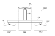
- FIG. 3 shows a left side view of the drone 100A of this embodiment.
- the downfosh region 32L of the inner propeller 20L and the downfosh regions 30L1, 30L2 of the outer propellers 14L1, 14L2 do not overlap. Therefore, the wind caused by the down-fosh of the inner propeller 20L does not hit the outer propellers 14L1 and 14L2, so that the lift can be prevented from being reduced. Therefore, waste of energy can be eliminated.
- the outer propellers 14L1 and 14L2 are arranged above the struts 12L and 12R.
- the lift decreases.
- the outer propellers 14L1 and 14L2 are arranged below the struts 12L and 12R.
- the downwash of the outer propellers 14L1 and 14L2 can prevent the wind from pushing the struts 12L and 12R downward, thereby preventing a decrease in lift force. Therefore, waste of energy can be eliminated.
- Each modified drone includes a motor that rotates the propeller, but for the sake of simplicity and clarity, the description of the motor is omitted below.
- the drones of the modifications shown in FIGS. 4 to 11 mainly differ from the drones of the above embodiments in the arrangement position and number of propellers and the number of struts.
- the struts are represented by lines in FIGS. 4-11.
- FIG. 4 shows a schematic left side view of the drone 100B of the first modified example. As shown in FIG. 4, in the drone 100B, the left rear outer propeller 14L2 is arranged above the rear end side of the column 12L.
- FIG. 5 shows a schematic left side view of a drone 100C of a second modified example.
- the drone 100C not only the left rear outer propeller 14L2 but also the left front outer propeller 14L1 are arranged above the rear end side of the column 12L.
- the configurations of FIGS. 1 and 5 are combined for the outer propellers. may be placed.
- FIG. 6 shows a schematic left side view of a drone 100D of a third modified example
- FIG. 7 shows a schematic left side view of a drone 100E of a fourth modified example.
- the struts 18L of the drones 100D and 100E are located below the struts 12L. 6 is the same as the drone 100B of FIG. 4, and the configuration of the drone 100E of the fourth modification of FIG. 1 is the same as the drone 100A of the above embodiment.
- the support 18L may be positioned below the support 12L.
- the above-described embodiment includes two struts 18L, 18R and two inner propellers 20L, 20R provided at the other ends of the two struts 18L, 18R.
- the technology of the present disclosure is not limited to this.
- fifth to seventh modifications will be described. Since the fifth to seventh modifications have the same configuration as the above-described embodiment, they are similar to the above-described embodiment.
- the same reference numerals are given to the same configurations, and the description thereof will be omitted, and mainly the portions different from the above-described embodiment will be described.
- FIG. 8 shows a schematic perspective view of a drone 100F of a fifth modified example.
- Drone 100F replaces two struts 18L and 18R with one strut 18M, one end of which is connected to the center of main body 10 (not shown in FIG. 8), and two inner propellers 20L and 20R. , and one inner propeller 20M provided at the other end (ie, upper end) of the strut 18M.
- the first to fourth modifications may also include one strut 18M and one inner propeller 20M.
- FIG. 9 shows a schematic perspective view of the drone 100G of the sixth modified example.
- the drone 100G further includes the following configuration in addition to the configuration of the drone 100A of the embodiment described above.
- the drone 100G includes a support 12M connected to the main body 10 whose longitudinal direction matches the longitudinal direction of the supports 12L and 12M, and a support 18L and 18R whose longitudinal direction matches the longitudinal direction of the main body. 10 (not shown in FIG. 9), an outer propeller 20M1 provided below the front end of the support 12M, and an outer propeller provided below the rear end of the support 12M. 20M2, and an inner propeller 20M provided at the other end (eg, upper end) of the strut 18M.
- the first to fourth modifications may also have these configurations (12M, 18M, 20M1, 20M2, 20M) like the sixth modification.
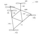
- FIG. 10 shows a schematic perspective view of the drone 100H of the seventh modification
- FIG. 11 shows a schematic left side view of the drone of the seventh modification.
- the two struts 12L and 12R are arranged in the same direction, and the two outer propellers 14L1 and 14R1 are arranged below the front ends of the two struts 12L and 12R.
- the drone 100H includes two struts 12LL and 12RR with front ends connected together instead of the two struts 12L and 12R, and two outer propellers 14L1. , 14R1, the outer propeller 14LR is provided below the front ends of the two struts 12LL, 12RR.
- FIG. 12 shows a schematic left side view of the drone 100I of the eighth modified example.
- the downfosh area 32L of the inner propeller 20L and the downfosh areas 30L1 and 30L2 of the outer propellers 14L1 and 14L2 do not overlap.
- the longitudinal length of the strut 12LS is set shorter than the longitudinal length of the strut 12L in the above-described embodiment.
- the traveling direction of the drone 100I that is, the size in the front-rear direction can be made smaller than the size in the front-rear direction of the conventional drone.
- the outer propeller is provided such that the downfosh region of the inner propeller 2 and the downfosh region of the outer propeller partially overlap each other.
- the length in the longitudinal direction of the supporting column may be shorter than the length in the longitudinal direction of the supporting column 12L in the above-described embodiment.
- the flight controller controls the motors 16L1, 16L2, 16R1, 16R2 and the motors 22L, 22R according to signals from the remote controller, thereby controlling the outer propellers 14L1, 14L2, 14R1, 14R2 and the inner propellers. It controls the rotation of each propeller 20L, 20R. This causes the drone 100A to fly according to the signal from the remote control device.
- FIG. 13A shows a schematic left side view showing the flight state of the drone 100A of the embodiment described above.
- the air regions A3 utilized by the inner propellers 20L, 20R are different from the air regions A1, A3 utilized by the outer propellers 14L1, 14L2, 14R1, 14R2.
- FIG. 13B shows the plane of rotation of the left inner propeller 20L of the drone 100A.
- the air area A3 utilized by the inner propellers 20L, 20R is determined by the surface of rotation 20LS of the inner propeller 20L, and the air areas A1, A2 utilized by the outer propellers 14L1, 14L2, 14R1, 14R2 are defined by the outer propellers 14L1, 14L2, It is determined by the plane of rotation of 14R1 and 14R2.
- the flight controller of the drone 100A controls the outer propellers 14L1, 14L2, 14R1, 14R2 and the outer propellers 14L1, 14L2, 14R1, 14R2 and Adjust the rotational speed of at least one of the inner propellers 20L, 20R.
- R is the lowest point of the inner propeller 20L
- S is the highest point of the rear outer propeller 14L2. It is the inclination angle of the drone 100A when the lower point R coincides with the highest point S of the rear outer propeller 14L2.
- the angle ⁇ d is the front outer side. This is the inclination angle of the drone 100A when the highest point T of the propeller 14L1 coincides with the lowest point U of the rear outer propeller 14L2.
- the flight controller makes the rotation speed of the rear outer propellers 14L2 and 14R2 higher than the rotation speed of the front outer propellers 14L1 and 14R1 so that the drone 100A flies at an angle ⁇ with respect to the traveling direction. Enlarge.
- the flight controller increases the rotation speed of the inner propellers 20L and 20R more than the rotation speed of the outer propellers 14L1 and 14R1 on the front side, or increases the rotation speed of the outer propellers 14L1 and 14R1 on the front side to that of the outer propellers 14L2 and 14R2 on the rear side. It may be smaller than the rotational speed.
- the angle at which the drone is tilted is adjusted so that the area of air used by the inner propeller differs from the area of air used by the outer propeller when the drone flies as described above. The same applies.
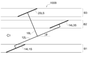
- FIG. 14 shows the flight state of the drone 100B of the first modified example.
- the area B2 of the air utilized by the outer propeller defined by the surface of rotation 14L3S of the left rear outer propeller is defined by the surface of rotation 20LS of the left inner propeller. is different from the region B3 of .
- the area B1 of the air used by the outer propeller which is determined by the rotation surface 14L1S of the left front outer propeller, differs from the areas B2 and B3.
- the flight controller controls the rotation speed of the front outer propellers 14L1 and 14R1 so that the drone 100A is inclined at an angle ⁇ with respect to the traveling direction. increase the rotational speed of the outer propellers 14L2 and 14R2 on the side.
- the flight controller increases the rotation speed of the inner propellers 20L and 20R more than the rotation speed of the outer propellers 14L1 and 14R1 on the front side, or increases the rotation speed of the outer propellers 14L1 and 14R1 on the front side to that of the outer propellers 14L2 and 14R2 on the rear side. It may be smaller than the rotational speed.
- FIG. 15 shows the flight state of the drone 100C of the second modified example.
- the area C2 of the air utilized by the outer propeller defined by the surface of rotation 14L3S of the left rear outer propeller is defined by the surface of rotation 20LS of the left inner propeller. is different from the region C3 of .
- the area C1 of the air used by the outer propeller, which is determined by the rotation surface 14L4S of the left front outer propeller, differs from the areas C2 and C3.
- the flight controller controls the rotational speed of the front outer propellers 14L1 and 14R1 so that the drone 100A is inclined at an angle ⁇ with respect to the direction of travel. increase the rotational speed of the outer propellers 14L2 and 14R2 on the side.
- the flight controller increases the rotation speed of the inner propellers 20L and 20R more than the rotation speed of the outer propellers 14L1 and 14R1 on the front side, or increases the rotation speed of the outer propellers 14L1 and 14R1 on the front side to that of the outer propellers 14L2 and 14R2 on the rear side. It may be smaller than the rotational speed.
- the size and length of the outer propeller and inner propeller will be explained.
- the size and length of each drone, outer propeller and inner propeller in the above-described embodiments and modifications are the same.
- the size and length of each of the outer propellers 14L1, 14L2, 14R1, 14R2 and the inner propellers 20L, 20R of the drone 100A of the above embodiment are the same.
- the technology of the present disclosure is not limited to this.
- FIG. 16 shows a schematic left side view of the drone 100J of the ninth modification.
- the size and length of the left inner propeller 20LL are larger than the left outer propellers 14L1 and 14L2, and the torque value is also larger.
- the left propeller has a large size, length, and torque value. Therefore, when any one of the outer propellers stops rotating, the lift force of the outer propeller that stops rotating can be compensated for by the drones of the above-described embodiments and modifications.
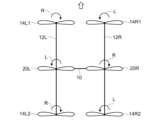
- FIG. 17 shows the rotation direction of each propeller during flight of the drone 100A of the embodiment described above.
- the two right outer propellers 14R1 and 14R2 rotate in one rotational direction L
- the two left outer propellers 14L1 and 14L2 rotate in the other rotational direction.
- R one right inner propeller 20R rotates in the other rotational direction R
- one left inner propeller 20L rotates in one rotational direction L.
- one rotation direction L is a left rotation direction when the drone 100A is viewed from above
- the other rotation direction R is a right rotation direction when the drone 100A is viewed from above.
- One rotation direction may be the right rotation direction
- the other rotation direction may be the left rotation direction.
- the left and right propellers rotate in directions opposite to each other, and the outer propeller and inner propeller rotate in opposite directions to other modifications.
Landscapes
- Engineering & Computer Science (AREA)
- Aviation & Aerospace Engineering (AREA)
- Toys (AREA)
Priority Applications (2)
| Application Number | Priority Date | Filing Date | Title |
|---|---|---|---|
| JP2023572280A JPWO2023132015A1 (https=) | 2022-01-05 | 2022-01-05 | |
| PCT/JP2022/000127 WO2023132015A1 (ja) | 2022-01-05 | 2022-01-05 | 飛行体及び飛行体の飛行方法 |
Applications Claiming Priority (1)
| Application Number | Priority Date | Filing Date | Title |
|---|---|---|---|
| PCT/JP2022/000127 WO2023132015A1 (ja) | 2022-01-05 | 2022-01-05 | 飛行体及び飛行体の飛行方法 |
Publications (1)
| Publication Number | Publication Date |
|---|---|
| WO2023132015A1 true WO2023132015A1 (ja) | 2023-07-13 |
Family
ID=87073470
Family Applications (1)
| Application Number | Title | Priority Date | Filing Date |
|---|---|---|---|
| PCT/JP2022/000127 Ceased WO2023132015A1 (ja) | 2022-01-05 | 2022-01-05 | 飛行体及び飛行体の飛行方法 |
Country Status (2)
| Country | Link |
|---|---|
| JP (1) | JPWO2023132015A1 (https=) |
| WO (1) | WO2023132015A1 (https=) |
Citations (9)
| Publication number | Priority date | Publication date | Assignee | Title |
|---|---|---|---|---|
| JP2016088111A (ja) * | 2014-10-29 | 2016-05-23 | ヤンマー株式会社 | ヘリコプター |
| CN105667780A (zh) * | 2016-04-14 | 2016-06-15 | 刘海涛 | 多旋翼飞行器 |
| CN107140192A (zh) * | 2017-04-27 | 2017-09-08 | 陶霖密 | 一种混合动力无人机 |
| JP2018134903A (ja) * | 2017-02-20 | 2018-08-30 | 株式会社自律制御システム研究所 | 無人航空機 |
| CN208715480U (zh) * | 2018-04-28 | 2019-04-09 | 新疆农业大学 | 一种基于物联网技术的实验用无人机系统 |
| CN110422020A (zh) * | 2019-09-05 | 2019-11-08 | 北京理工大学 | 一种飞行器及陆空两栖车 |
| JP2020006801A (ja) * | 2018-07-09 | 2020-01-16 | 独立行政法人国立高等専門学校機構 | 無人飛行体 |
| US20200140070A1 (en) * | 2018-08-21 | 2020-05-07 | SkyMul Inc. | Aerial vehicle |
| JP2021037932A (ja) * | 2019-08-30 | 2021-03-11 | 株式会社エアロジーラボ | マルチコプター |
Family Cites Families (1)
| Publication number | Priority date | Publication date | Assignee | Title |
|---|---|---|---|---|
| JP6770767B2 (ja) * | 2020-01-17 | 2020-10-21 | 株式会社石川エナジーリサーチ | エンジン搭載自立型飛行装置 |
-
2022
- 2022-01-05 JP JP2023572280A patent/JPWO2023132015A1/ja active Pending
- 2022-01-05 WO PCT/JP2022/000127 patent/WO2023132015A1/ja not_active Ceased
Patent Citations (9)
| Publication number | Priority date | Publication date | Assignee | Title |
|---|---|---|---|---|
| JP2016088111A (ja) * | 2014-10-29 | 2016-05-23 | ヤンマー株式会社 | ヘリコプター |
| CN105667780A (zh) * | 2016-04-14 | 2016-06-15 | 刘海涛 | 多旋翼飞行器 |
| JP2018134903A (ja) * | 2017-02-20 | 2018-08-30 | 株式会社自律制御システム研究所 | 無人航空機 |
| CN107140192A (zh) * | 2017-04-27 | 2017-09-08 | 陶霖密 | 一种混合动力无人机 |
| CN208715480U (zh) * | 2018-04-28 | 2019-04-09 | 新疆农业大学 | 一种基于物联网技术的实验用无人机系统 |
| JP2020006801A (ja) * | 2018-07-09 | 2020-01-16 | 独立行政法人国立高等専門学校機構 | 無人飛行体 |
| US20200140070A1 (en) * | 2018-08-21 | 2020-05-07 | SkyMul Inc. | Aerial vehicle |
| JP2021037932A (ja) * | 2019-08-30 | 2021-03-11 | 株式会社エアロジーラボ | マルチコプター |
| CN110422020A (zh) * | 2019-09-05 | 2019-11-08 | 北京理工大学 | 一种飞行器及陆空两栖车 |
Also Published As
| Publication number | Publication date |
|---|---|
| JPWO2023132015A1 (https=) | 2023-07-13 |
Similar Documents
| Publication | Publication Date | Title |
|---|---|---|
| JP6158459B2 (ja) | マルチコプター | |
| EP3954609B1 (en) | Rotary-wing aircraft | |
| US20050178879A1 (en) | VTOL tailsitter flying wing | |
| US20170021924A1 (en) | Control system and strategy for tail sitter | |
| US20190009899A1 (en) | Hybrid vtol fixed-wing drone having wing-tip propellers | |
| US20150344134A1 (en) | High Performance VTOL Aircraft | |
| JP2017528355A (ja) | 高性能垂直離着陸航空機 | |
| JP7120645B2 (ja) | 回転翼機 | |
| KR102032243B1 (ko) | 틸트프롭 비행체 | |
| US12208929B2 (en) | Rotorcraft | |
| KR102245397B1 (ko) | 다중회전익 무인비행체 | |
| US10913529B1 (en) | Landing gear | |
| WO2023132015A1 (ja) | 飛行体及び飛行体の飛行方法 | |
| US12420959B2 (en) | Flight unit for an aircraft | |
| JP7240050B2 (ja) | 回転翼機 | |
| CN113753214B (zh) | 一种半升力飞艇 | |
| CN110361984B (zh) | 一种增加阻力的交叉舵耗能方法 | |
| CN119902549B (zh) | 飞行器控制方法、装置以及飞行器 | |
| KR101788822B1 (ko) | 관통홀을 구비한 고효율 드론 | |
| KR102713075B1 (ko) | 추력 벡터 제어가 가능한 드론 및 이의 제어 방법 | |
| US12552562B2 (en) | Concentric vertical ducted propulsion for aerial vehicles | |
| US12497198B2 (en) | Aircraft | |
| CN108674628A (zh) | 一种环形结构尾座式垂直起降无人飞行器 | |
| WO2023188269A1 (ja) | 回転翼機 | |
| WO2024202127A1 (ja) | 電動飛行体の制御方法 |
Legal Events
| Date | Code | Title | Description |
|---|---|---|---|
| 121 | Ep: the epo has been informed by wipo that ep was designated in this application |
Ref document number: 22917652 Country of ref document: EP Kind code of ref document: A1 |
|
| NENP | Non-entry into the national phase |
Ref country code: DE |
|
| ENP | Entry into the national phase |
Ref document number: 2023572280 Country of ref document: JP Kind code of ref document: A |
|
| 122 | Ep: pct application non-entry in european phase |
Ref document number: 22917652 Country of ref document: EP Kind code of ref document: A1 |