WO2023127538A1 - 液晶性組成物、硬化物、光学異方性層、光学素子、導光素子 - Google Patents
液晶性組成物、硬化物、光学異方性層、光学素子、導光素子 Download PDFInfo
- Publication number
- WO2023127538A1 WO2023127538A1 PCT/JP2022/046330 JP2022046330W WO2023127538A1 WO 2023127538 A1 WO2023127538 A1 WO 2023127538A1 JP 2022046330 W JP2022046330 W JP 2022046330W WO 2023127538 A1 WO2023127538 A1 WO 2023127538A1
- Authority
- WO
- WIPO (PCT)
- Prior art keywords
- liquid crystalline
- compound
- group
- optically anisotropic
- antioxidant
- Prior art date
- Legal status (The legal status is an assumption and is not a legal conclusion. Google has not performed a legal analysis and makes no representation as to the accuracy of the status listed.)
- Ceased
Links
Images




Classifications
-
- C—CHEMISTRY; METALLURGY
- C09—DYES; PAINTS; POLISHES; NATURAL RESINS; ADHESIVES; COMPOSITIONS NOT OTHERWISE PROVIDED FOR; APPLICATIONS OF MATERIALS NOT OTHERWISE PROVIDED FOR
- C09K—MATERIALS FOR MISCELLANEOUS APPLICATIONS, NOT PROVIDED FOR ELSEWHERE
- C09K19/00—Liquid crystal materials
- C09K19/52—Liquid crystal materials characterised by components which are not liquid crystals, e.g. additives with special physical aspect: solvents, solid particles
- C09K19/54—Additives having no specific mesophase characterised by their chemical composition
-
- C—CHEMISTRY; METALLURGY
- C08—ORGANIC MACROMOLECULAR COMPOUNDS; THEIR PREPARATION OR CHEMICAL WORKING-UP; COMPOSITIONS BASED THEREON
- C08F—MACROMOLECULAR COMPOUNDS OBTAINED BY REACTIONS ONLY INVOLVING CARBON-TO-CARBON UNSATURATED BONDS
- C08F20/00—Homopolymers and copolymers of compounds having one or more unsaturated aliphatic radicals, each having only one carbon-to-carbon double bond, and only one being terminated by only one carboxyl radical or a salt, anhydride, ester, amide, imide or nitrile thereof
- C08F20/02—Monocarboxylic acids having less than ten carbon atoms, Derivatives thereof
- C08F20/10—Esters
- C08F20/20—Esters of polyhydric alcohols or polyhydric phenols, e.g. 2-hydroxyethyl (meth)acrylate or glycerol mono-(meth)acrylate
-
- C—CHEMISTRY; METALLURGY
- C08—ORGANIC MACROMOLECULAR COMPOUNDS; THEIR PREPARATION OR CHEMICAL WORKING-UP; COMPOSITIONS BASED THEREON
- C08F—MACROMOLECULAR COMPOUNDS OBTAINED BY REACTIONS ONLY INVOLVING CARBON-TO-CARBON UNSATURATED BONDS
- C08F20/00—Homopolymers and copolymers of compounds having one or more unsaturated aliphatic radicals, each having only one carbon-to-carbon double bond, and only one being terminated by only one carboxyl radical or a salt, anhydride, ester, amide, imide or nitrile thereof
- C08F20/02—Monocarboxylic acids having less than ten carbon atoms, Derivatives thereof
- C08F20/10—Esters
- C08F20/26—Esters containing oxygen in addition to the carboxy oxygen
- C08F20/30—Esters containing oxygen in addition to the carboxy oxygen containing aromatic rings in the alcohol moiety
-
- C—CHEMISTRY; METALLURGY
- C08—ORGANIC MACROMOLECULAR COMPOUNDS; THEIR PREPARATION OR CHEMICAL WORKING-UP; COMPOSITIONS BASED THEREON
- C08F—MACROMOLECULAR COMPOUNDS OBTAINED BY REACTIONS ONLY INVOLVING CARBON-TO-CARBON UNSATURATED BONDS
- C08F22/00—Homopolymers and copolymers of compounds having one or more unsaturated aliphatic radicals each having only one carbon-to-carbon double bond, and at least one being terminated by a carboxyl radical and containing at least one other carboxyl radical in the molecule; Salts, anhydrides, esters, amides, imides or nitriles thereof
- C08F22/10—Esters
- C08F22/12—Esters of phenols or saturated alcohols
- C08F22/20—Esters containing oxygen in addition to the carboxy oxygen
-
- C—CHEMISTRY; METALLURGY
- C08—ORGANIC MACROMOLECULAR COMPOUNDS; THEIR PREPARATION OR CHEMICAL WORKING-UP; COMPOSITIONS BASED THEREON
- C08F—MACROMOLECULAR COMPOUNDS OBTAINED BY REACTIONS ONLY INVOLVING CARBON-TO-CARBON UNSATURATED BONDS
- C08F22/00—Homopolymers and copolymers of compounds having one or more unsaturated aliphatic radicals each having only one carbon-to-carbon double bond, and at least one being terminated by a carboxyl radical and containing at least one other carboxyl radical in the molecule; Salts, anhydrides, esters, amides, imides or nitriles thereof
- C08F22/10—Esters
- C08F22/12—Esters of phenols or saturated alcohols
- C08F22/24—Esters containing sulfur
-
- C—CHEMISTRY; METALLURGY
- C08—ORGANIC MACROMOLECULAR COMPOUNDS; THEIR PREPARATION OR CHEMICAL WORKING-UP; COMPOSITIONS BASED THEREON
- C08F—MACROMOLECULAR COMPOUNDS OBTAINED BY REACTIONS ONLY INVOLVING CARBON-TO-CARBON UNSATURATED BONDS
- C08F38/00—Homopolymers and copolymers of compounds having one or more carbon-to-carbon triple bonds
-
- C—CHEMISTRY; METALLURGY
- C08—ORGANIC MACROMOLECULAR COMPOUNDS; THEIR PREPARATION OR CHEMICAL WORKING-UP; COMPOSITIONS BASED THEREON
- C08K—Use of inorganic or non-macromolecular organic substances as compounding ingredients
- C08K5/00—Use of organic ingredients
- C08K5/04—Oxygen-containing compounds
- C08K5/15—Heterocyclic compounds having oxygen in the ring
- C08K5/151—Heterocyclic compounds having oxygen in the ring having one oxygen atom in the ring
- C08K5/1545—Six-membered rings
-
- C—CHEMISTRY; METALLURGY
- C08—ORGANIC MACROMOLECULAR COMPOUNDS; THEIR PREPARATION OR CHEMICAL WORKING-UP; COMPOSITIONS BASED THEREON
- C08K—Use of inorganic or non-macromolecular organic substances as compounding ingredients
- C08K5/00—Use of organic ingredients
- C08K5/16—Nitrogen-containing compounds
- C08K5/17—Amines; Quaternary ammonium compounds
-
- C—CHEMISTRY; METALLURGY
- C08—ORGANIC MACROMOLECULAR COMPOUNDS; THEIR PREPARATION OR CHEMICAL WORKING-UP; COMPOSITIONS BASED THEREON
- C08L—COMPOSITIONS OF MACROMOLECULAR COMPOUNDS
- C08L33/00—Compositions of homopolymers or copolymers of compounds having one or more unsaturated aliphatic radicals, each having only one carbon-to-carbon double bond, and only one being terminated by only one carboxyl radical, or of salts, anhydrides, esters, amides, imides or nitriles thereof; Compositions of derivatives of such polymers
- C08L33/04—Homopolymers or copolymers of esters
-
- C—CHEMISTRY; METALLURGY
- C09—DYES; PAINTS; POLISHES; NATURAL RESINS; ADHESIVES; COMPOSITIONS NOT OTHERWISE PROVIDED FOR; APPLICATIONS OF MATERIALS NOT OTHERWISE PROVIDED FOR
- C09K—MATERIALS FOR MISCELLANEOUS APPLICATIONS, NOT PROVIDED FOR ELSEWHERE
- C09K19/00—Liquid crystal materials
- C09K19/04—Liquid crystal materials characterised by the chemical structure of the liquid crystal components, e.g. by a specific unit
- C09K19/06—Non-steroidal liquid crystal compounds
- C09K19/34—Non-steroidal liquid crystal compounds containing at least one heterocyclic ring
- C09K19/3491—Non-steroidal liquid crystal compounds containing at least one heterocyclic ring having sulfur as hetero atom
-
- C—CHEMISTRY; METALLURGY
- C09—DYES; PAINTS; POLISHES; NATURAL RESINS; ADHESIVES; COMPOSITIONS NOT OTHERWISE PROVIDED FOR; APPLICATIONS OF MATERIALS NOT OTHERWISE PROVIDED FOR
- C09K—MATERIALS FOR MISCELLANEOUS APPLICATIONS, NOT PROVIDED FOR ELSEWHERE
- C09K19/00—Liquid crystal materials
- C09K19/04—Liquid crystal materials characterised by the chemical structure of the liquid crystal components, e.g. by a specific unit
- C09K19/06—Non-steroidal liquid crystal compounds
- C09K19/34—Non-steroidal liquid crystal compounds containing at least one heterocyclic ring
- C09K19/3491—Non-steroidal liquid crystal compounds containing at least one heterocyclic ring having sulfur as hetero atom
- C09K19/3497—Non-steroidal liquid crystal compounds containing at least one heterocyclic ring having sulfur as hetero atom the heterocyclic ring containing sulfur and nitrogen atoms
-
- C—CHEMISTRY; METALLURGY
- C09—DYES; PAINTS; POLISHES; NATURAL RESINS; ADHESIVES; COMPOSITIONS NOT OTHERWISE PROVIDED FOR; APPLICATIONS OF MATERIALS NOT OTHERWISE PROVIDED FOR
- C09K—MATERIALS FOR MISCELLANEOUS APPLICATIONS, NOT PROVIDED FOR ELSEWHERE
- C09K19/00—Liquid crystal materials
- C09K19/04—Liquid crystal materials characterised by the chemical structure of the liquid crystal components, e.g. by a specific unit
- C09K19/38—Polymers
- C09K19/3833—Polymers with mesogenic groups in the side chain
- C09K19/3842—Polyvinyl derivatives
- C09K19/3852—Poly(meth)acrylate derivatives
-
- G—PHYSICS
- G02—OPTICS
- G02B—OPTICAL ELEMENTS, SYSTEMS OR APPARATUS
- G02B5/00—Optical elements other than lenses
- G02B5/18—Diffraction gratings
-
- G—PHYSICS
- G02—OPTICS
- G02B—OPTICAL ELEMENTS, SYSTEMS OR APPARATUS
- G02B5/00—Optical elements other than lenses
- G02B5/30—Polarising elements
-
- G—PHYSICS
- G02—OPTICS
- G02B—OPTICAL ELEMENTS, SYSTEMS OR APPARATUS
- G02B5/00—Optical elements other than lenses
- G02B5/30—Polarising elements
- G02B5/3016—Polarising elements involving passive liquid crystal elements
-
- C—CHEMISTRY; METALLURGY
- C09—DYES; PAINTS; POLISHES; NATURAL RESINS; ADHESIVES; COMPOSITIONS NOT OTHERWISE PROVIDED FOR; APPLICATIONS OF MATERIALS NOT OTHERWISE PROVIDED FOR
- C09K—MATERIALS FOR MISCELLANEOUS APPLICATIONS, NOT PROVIDED FOR ELSEWHERE
- C09K19/00—Liquid crystal materials
- C09K19/04—Liquid crystal materials characterised by the chemical structure of the liquid crystal components, e.g. by a specific unit
- C09K2019/0444—Liquid crystal materials characterised by the chemical structure of the liquid crystal components, e.g. by a specific unit characterized by a linking chain between rings or ring systems, a bridging chain between extensive mesogenic moieties or an end chain group
- C09K2019/0448—Liquid crystal materials characterised by the chemical structure of the liquid crystal components, e.g. by a specific unit characterized by a linking chain between rings or ring systems, a bridging chain between extensive mesogenic moieties or an end chain group the end chain group being a polymerizable end group, e.g. -Sp-P or acrylate
-
- C—CHEMISTRY; METALLURGY
- C09—DYES; PAINTS; POLISHES; NATURAL RESINS; ADHESIVES; COMPOSITIONS NOT OTHERWISE PROVIDED FOR; APPLICATIONS OF MATERIALS NOT OTHERWISE PROVIDED FOR
- C09K—MATERIALS FOR MISCELLANEOUS APPLICATIONS, NOT PROVIDED FOR ELSEWHERE
- C09K19/00—Liquid crystal materials
- C09K19/04—Liquid crystal materials characterised by the chemical structure of the liquid crystal components, e.g. by a specific unit
- C09K19/06—Non-steroidal liquid crystal compounds
- C09K19/08—Non-steroidal liquid crystal compounds containing at least two non-condensed rings
- C09K19/10—Non-steroidal liquid crystal compounds containing at least two non-condensed rings containing at least two benzene rings
- C09K19/12—Non-steroidal liquid crystal compounds containing at least two non-condensed rings containing at least two benzene rings at least two benzene rings directly linked, e.g. biphenyls
- C09K2019/121—Compounds containing phenylene-1,4-diyl (-Ph-)
- C09K2019/122—Ph-Ph
Definitions
- the present invention relates to liquid crystalline compositions, cured products, optically anisotropic layers, optical elements, and light guide elements.
- an optical element capable of obtaining diffracted light with a large diffraction angle and high diffraction efficiency is composed of a cured layer of a liquid crystalline composition containing a tolan compound as a liquid crystalline compound, and a predetermined liquid crystal
- An optical element with an optically anisotropic layer having an orientation pattern is disclosed.
- the inventors of the present invention prepared a film made of a liquid crystalline composition containing a tolane compound and studied it with reference to Patent Document 1.
- the liquid crystalline composition containing a tolane compound exhibited a high refractive index anisotropy ⁇ n.
- the film formed from this liquid crystalline composition has a high diffraction efficiency, it is difficult to maintain the above optical properties due to photodegradation of the tolan compound (in other words, the diffraction efficiency increases due to photodegradation of the tolan compound). may decrease). In other words, it has been clarified that there is room for improving the light resistance of the film formed from the liquid crystalline composition.
- a film formed from a liquid crystalline composition is also required to have excellent orientation of the liquid crystalline compound.
- an object of the present invention is to provide a liquid crystalline composition capable of forming a film having excellent light resistance and having excellent orientation of a liquid crystalline compound in the film.
- Another object of the present invention is to provide a cured product, an optically anisotropic layer, an optical element, and a light guide element obtained from the liquid crystalline composition.
- a liquid crystalline composition containing a compound A having a partial structure represented by formula (I) described below and an antioxidant When the compound A exhibits liquid crystallinity and the composition does not contain a liquid crystalline compound B having a structure different from that of the compound A, the distance between the Hansen solubility parameter of the antioxidant and the Hansen solubility parameter of the compound A ⁇ HSP is 10.5 MPa 0.5 or less, When the composition contains the liquid crystalline compound B, the distance ⁇ HSP between the Hansen solubility parameter of the antioxidant and the average Hansen solubility parameter of the Hansen solubility parameter of the compound A and the Hansen solubility parameter of the liquid crystalline compound B is 10.5 MPa 0.5 or less, liquid crystalline composition.
- the content of the antioxidant is 0.01 to 5 masses relative to the content of the compound A. % and When the composition contains the liquid crystalline compound B, the content of the antioxidant is 0.01 to 5% by mass with respect to the total content of the compound A and the liquid crystalline compound B [1 ] to [10].
- the antioxidant contains one or more selected from the group consisting of tertiary amines, hydroxylamines, tocopherols, catechol ethers, hindered phenols, and hindered amines [1] to [ 11].
- [18] A cured product obtained by curing the liquid crystalline composition according to any one of [1] to [17].
- An optically anisotropic layer comprising the cured product of [18].
- the optically anisotropic layer has an orientation pattern, The optical difference according to [19], wherein the orientation pattern is an orientation pattern in which the direction of the optic axis derived from the liquid crystalline compound contained in the composition is continuously changed along at least one in-plane direction. tropic layer.
- a light guide element including the optical element according to [21] and a light guide plate.
- the liquid crystalline composition which can form the film
- FIG. 1 is a schematic diagram showing an embodiment of an optically anisotropic layer
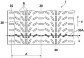
- FIG. 2 is a schematic plan view of the optically anisotropic layer shown in FIG. 1.
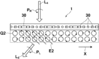
- FIG. 3 is a conceptual diagram showing the action of the optically anisotropic layer shown in FIG. 2
- FIG. 3 is a conceptual diagram showing the action of the optically anisotropic layer shown in FIG. 2
- FIG. 2 is a schematic diagram showing another example of an optically anisotropic layer
- FIG. 2 is a schematic diagram showing another example of an optically anisotropic layer;
- (meth)acryloyloxy group is a notation representing both an acryloyloxy group and a methacryloyloxy group
- “(meth)acrylate” is a notation representing both acrylate and methacrylate.
- a description that does not describe substitution or unsubstituted includes a group having a substituent as well as a group having no substituent.
- an "alkyl group” includes not only an alkyl group having no substituent (unsubstituted alkyl group) but also an alkyl group having a substituent (substituted alkyl group).
- substituent when simply referred to as a "substituent", the substituent includes, for example, the following substituent L.
- substituent L examples include an alkyl group having 1 to 10 carbon atoms, an alkoxy group having 1 to 10 carbon atoms, an alkylamino group having 1 to 10 carbon atoms, an alkylthio group having 1 to 10 carbon atoms, and an alkylthio group having 1 to 10 carbon atoms.
- alkanoyl group alkanoyl group, alkanoyloxy group having 1 to 10 carbon atoms, alkanoylamino group having 1 to 10 carbon atoms, alkanoylthio group having 1 to 10 carbon atoms, alkyloxycarbonyl group having 2 to 10 carbon atoms, 2 to 10 carbon atoms
- Substituent L also includes a group substituted with CH— or —C ⁇ C—.
- the above group has two or more —CH 2 —, one —CH 2 — is replaced by —O—, and the adjacent one —CH 2 — is replaced by —CO—, resulting in an ester group ( -O-CO-) may be formed.
- the group described as the substituent L has a hydrogen atom
- at least one of the hydrogen atoms contained in the group is replaced with at least one selected from the group consisting of a fluorine atom and a polymerizable group.
- group is also included in the substituent L.
- the polymerizable group include an ethylenically unsaturated group and a ring-polymerizable group, among which substituents selected from polymerizable groups P described later are preferable.
- substituent L examples include, among others, an alkyl group having 1 to 10 carbon atoms, an alkoxy group having 1 to 10 carbon atoms, an alkanoyl group having 1 to 10 carbon atoms, an alkanoyloxy group having 1 to 10 carbon atoms, and a alkanoyloxy group having 1 to 10 carbon atoms.
- alkyloxycarbonyl group trifluoromethyl group, hydroxy group, carboxy group, cyano group, nitro group, or halogen atom
- alkyl group having 1 to 10 carbon atoms alkoxy group having 1 to 10 carbon atoms, carbon number 2 to 10 alkanoyl groups, alkanoyloxy groups having 2 to 10 carbon atoms, alkyloxycarbonyl groups having 2 to 10 carbon atoms, trifluoromethyl groups, or halogen atoms are more preferable, alkyl groups having 1 to 6 carbon atoms, carbon More preferred are an alkoxy group having 1 to 6 carbon atoms, an alkanoyl group having 2 to 6 carbon atoms, an alkanoyloxy group having 2 to 6 carbon atoms, an alkyloxycarbonyl group having 2 to 6 carbon atoms, a trifluoromethyl group, or a fluorine atom.
- the polymerizable group when simply referred to as a "polymerizable group", includes, for example, the following polymerizable group P.
- Polymerizable group P examples include groups represented by any one of the following formulas (P-1) to (P-19).
- * in the following formula represents a bonding position
- Me represents a methyl group
- Et represents an ethyl group.
- formula (P-1) or formula (P-2) ((meth)acryloyloxy group) is preferable.
- the "solid content" of the composition means a component that forms a composition layer formed using the composition, and when the composition contains a solvent (organic solvent, water, etc.) , means all components except solvent.
- a liquid component is also regarded as a solid content.
- the thickness of the layer is measured at 10 points by observing a cross section cut by a microtome with a SEM (scanning electron microscope) or a TEM (transmission electron microscope). It is a value using the average value.
- the liquid crystalline composition of the present invention is A liquid crystalline composition comprising a compound A having a partial structure represented by formula (I) described below and an antioxidant,
- the compound A exhibits liquid crystallinity and the composition does not contain a liquid crystalline compound B having a structure different from that of the compound A (hereinafter also referred to as "liquid crystalline compound B")
- the Hansen solubility parameter of the antioxidant and the distance ⁇ HSP between the Hansen solubility parameter of compound A is 10.5 MPa 0.5 or less
- the distance ⁇ HSP between the Hansen solubility parameter of the antioxidant and the average Hansen solubility parameter of the Hansen solubility parameter of the compound A and the Hansen solubility parameter of the liquid crystalline compound B is 10.5 MPa 0.5 or less.
- liquid crystal compound A the compound A exhibiting liquid crystallinity
- non-liquid crystal compound A the compound A not exhibiting liquid crystallinity
- liquid crystalline compound B having a structure different from that of the compound A is a liquid crystalline compound having a structure different from that of the compound A, that is, a partial structure represented by formula (I) described later. is intended to be a liquid crystalline compound that does not have
- the film formed from the liquid crystalline composition of the present invention having the above structure has a high diffraction efficiency because the liquid crystalline composition contains the tolan compound (compound A), and can be used for a long time with suppressed photodegradation.
- a high diffraction efficiency can be maintained over a wide range (in other words, excellent light resistance).
- the orientation of the liquid crystalline compound in the film is also excellent.
- the liquid crystalline composition of the present invention contains an antioxidant, the generation of singlet oxygen, which causes photodegradation of the tolan compound, is suppressed. is considered to have excellent light resistance.
- the distance ⁇ HSP between the Hansen solubility parameter (HSP (Hansen solubility parameter) value) of the antioxidant and the HSP value of the liquid crystalline compound A (the liquid crystalline composition is a liquid crystalline compound A (corresponding to the first aspect described later)
- the distance ⁇ HSP between the HSP value of the antioxidant and the average HSP value of the compound A and the liquid crystalline compound B (the liquid crystalline composition is a compound When A and a liquid crystalline compound B are contained (corresponding to the second and third embodiments described later)) is set to a predetermined value or less, it is considered that the orientation of the liquid crystalline compound in the film is also excellent.
- the effect of the present invention is more excellent. There are cases where it is said.
- aspects of the liquid crystalline composition include, for example, the following aspects.
- Aspect 1 The liquid crystalline composition contains only the liquid crystalline compound A as a liquid crystalline compound, and the distance ⁇ HSP between the HSP value of the antioxidant and the HSP value of the compound A is 10.5 MPa 0.5 or less.
- Second Aspect The liquid crystalline composition contains a liquid crystalline compound A and a liquid crystalline compound B as liquid crystalline compounds, and the distance between the HSP value of the antioxidant and the average HSP value of the liquid crystalline compound A and the liquid crystalline compound B ⁇ HSP is 10.5 MPa 0.5 or less.
- the liquid crystalline composition contains a non-liquid crystalline compound A and a liquid crystalline compound B, and the distance ⁇ HSP between the HSP value of the antioxidant and the average HSP value of the non-liquid crystalline compound A and the liquid crystalline compound B is 10.5 MPa 0.5 or less.
- liquid crystal compound A the liquid crystal compound B, and the non-liquid crystal compound A are as described above.
- liquid crystalline composition of the first aspect does not contain another liquid crystalline compound (liquid crystalline compound B) having a structure different from that of the compound A.
- liquid crystalline composition each component in the liquid crystalline composition will be described below.
- the liquid crystalline composition may further contain various components such as a polymerization initiator to be described later.
- the liquid crystalline composition contains a compound (compound A) having a partial structure represented by formula (I) below.
- a 1 and A 2 each independently represent an optionally substituted aromatic hydrocarbon ring group or aromatic heterocyclic group. * represents a binding position.
- the aromatic hydrocarbon ring group may have a monocyclic structure or a polycyclic structure.
- the aromatic hydrocarbon ring group is not particularly limited, but is preferably an arylene group, more preferably an arylene group having 6 to 20 carbon atoms, more preferably an arylene group having 6 to 10 carbon atoms, and particularly preferably a phenylene group or a naphthylene group. .
- the aromatic heterocyclic group may have a monocyclic structure or a polycyclic structure. Among them, the aromatic heterocyclic group is preferably a 5- or 6-membered monocyclic aromatic heterocyclic group.
- the heteroatom contained in the aromatic heterocyclic group is not particularly limited, and examples thereof include a nitrogen atom, an oxygen atom, a sulfur atom and the like.
- the aromatic heterocyclic group is not particularly limited, but is preferably a heteroarylene group, more preferably a heteroarylene group having 3 to 20 carbon atoms, and still more preferably a heteroarylene group having 3 to 10 carbon atoms.
- the heteroatom contained in the heteroarylene group is preferably at least one selected from the group consisting of a nitrogen atom, an oxygen atom and a sulfur atom.
- the substituents that the aromatic hydrocarbon ring group and the aromatic heterocyclic group may have are not particularly limited, but substituents selected from the substituents L described above are preferable.
- Compound A may or may not exhibit liquid crystallinity.
- liquid crystalline compounds can be classified into a rod-like type and a disk-like type according to their shape. Furthermore, there are low-molecular-weight and high-molecular-weight types, respectively.
- Polymers generally refer to those having a degree of polymerization of 100 or more (Polymer Physics: Phase Transition Dynamics, Masao Doi, p. 2, Iwanami Shoten, 1992).
- the liquid crystal compound A may be any of the compounds described above, but among them, a rod-like liquid crystal compound is preferable.
- the liquid crystal compound A is preferably a liquid crystal compound having a polymerizable group in the molecule (hereinafter also referred to as "polymerizable liquid crystal compound").
- the polymerizable group include an ethylenically unsaturated group and a ring-polymerizable group. Specifically, for example, it is selected from a vinyl group, a styryl group, an allyl group, and the polymerizable group P described above. A substituent etc. are mentioned.
- the liquid crystalline compound A has a polymerizable group, it is preferred that one molecule has two or more polymerizable groups in order to fix the alignment.
- the molecular weight of compound A is, for example, preferably 200 to 100,000, more preferably 300 to 10,00, even more preferably 400 to 2,500.
- the said molecular weight means a weight average molecular weight.
- Compound A is preferably a compound represented by the following formula (II) in that the effect of the present invention is more excellent, and a compound represented by the following formula (III) or the following formula (IV). is more preferred.
- the compounds represented by formulas (II) to (IV) are described below.
- P 1 and P 2 each independently represent a hydrogen atom, a halogen atom, —CN, —NCS, or a polymerizable group.
- P 1 and P 2 are each independently preferably a polymerizable group.
- the polymerizable group is not particularly limited, but includes, for example, an ethylenically unsaturated group and a ring-polymerizable group, and is preferably a substituent selected from the polymerizable groups P described above.
- Sp 1 and Sp 2 each independently represent a single bond or a divalent linking group.
- Sp 1 and Sp 2 represent a divalent linking group containing at least one group selected from the group consisting of an aromatic hydrocarbon ring group, an aromatic heterocyclic group, and an aliphatic hydrocarbon ring group. do not have.
- the divalent linking group represented by Sp 1 and Sp 2 is not particularly limited, but an alkylene group (preferably an alkylene group having 1 to 20 carbon atoms), an alkenylene group (preferably an alkenylene group having 2 to 20 carbon atoms ), -O-, -S-, -CO-, -SO-, -SO2- , -COO-, -OCO-, -CO-S-, -S-CO-, -O-CO-O- , or a divalent linking group in which a plurality of these are combined is preferred.
- an alkylene group preferably an alkylene group having 1 to 20 carbon atoms
- an alkenylene group preferably an alkenylene group having 2 to 20 carbon atoms
- -O-, -S-, -CO- preferably an alkenylene group having 2 to 20 carbon atoms
- -O-, -S-, -CO- preferably an alkenylene group having 2 to 20 carbon atom
- Sp 1 and Sp 2 are each independently a single bond, or an alkylene group having 1 to 10 carbon atoms, -O-, -S-, -CO-, -COO-, -OCO-, or A divalent linking group combining a plurality of these is preferred, and a single bond, or an alkylene group having 1 to 6 carbon atoms, -O-, -S-, or a divalent linking group combining a plurality of these is more preferred.
- a single bond, an alkylene group having 1 to 4 carbon atoms, —O—, —S—, or a divalent linking group combining a plurality of these is more preferable.
- Z 1 and Z 2 each independently represent a single bond or a divalent linking group.
- the multiple Z 1 and the multiple Z 2 may be the same or different.
- Z 1 and Z 2 represent a divalent linking group containing at least one group selected from the group consisting of an aromatic hydrocarbon ring group, an aromatic heterocyclic group, and an aliphatic hydrocarbon ring group. do not have.
- the divalent linking group represented by Z 1 and Z 2 is not particularly limited, but an alkylene group (preferably an alkylene group having 1 to 20 carbon atoms), an alkenylene group (preferably an alkenylene group having 2 to 20 carbon atoms ), an alkynylene group (preferably an alkynylene group having 2 to 20 carbon atoms) , -O-, -S-, -CO-, -SO-, -SO2- , -COO-, -OCO-, -CO-S-, -S-CO-, -O-CO-O-, Alternatively, a divalent linking group obtained by combining a plurality of these is preferred.
- R represents a hydrogen atom or an alkyl group having 1 to 10 carbon atoms.
- R is preferably a hydrogen atom or an alkyl group having 1 to 6 carbon atoms, more preferably a hydrogen atom or an alkyl group having 1 to 4 carbon atoms, and still more preferably a hydrogen atom.
- R may each be same or different.
- Z 1 and Z 2 are each independently -CHRCHR-, -OCHR-, -CHRO-, -COO-, -OCO-, -CO-NH-, -NH-CO-, or - C ⁇ C- is preferred, and -CHRCHR-, -OCHR-, -CHRO- or -C ⁇ C- is more preferred.
- a 1 and A 2 each independently represent an optionally substituted aromatic hydrocarbon ring group or aromatic heterocyclic group.
- a 1 and A 2 have the same meanings as A 1 and A 2 in formula (I), and the preferred embodiments are also the same.
- B 1 and B 2 each independently represent an optionally substituted aromatic hydrocarbon ring group, aromatic heterocyclic group, or aliphatic hydrocarbon ring group.
- the plurality of B 1 's and the plurality of B 2 's may be the same or different.
- the aromatic hydrocarbon ring group may have a monocyclic structure or a polycyclic structure.
- the aromatic hydrocarbon ring group is not particularly limited, but is preferably an arylene group, more preferably an arylene group having 6 to 20 carbon atoms, more preferably an arylene group having 6 to 10 carbon atoms, and particularly preferably a phenylene group or a naphthylene group. .
- the aromatic heterocyclic group may have a monocyclic structure or a polycyclic structure. Among them, the aromatic heterocyclic group is preferably a 5- or 6-membered monocyclic aromatic heterocyclic group.
- the heteroatom contained in the aromatic heterocyclic group is not particularly limited, and examples thereof include a nitrogen atom, an oxygen atom, a sulfur atom and the like.
- the aromatic heterocyclic group is not particularly limited, but is preferably a heteroarylene group, more preferably a heteroarylene group having 3 to 20 carbon atoms, and still more preferably a heteroarylene group having 3 to 10 carbon atoms.
- the heteroatom contained in the heteroarylene group is preferably at least one selected from the group consisting of a nitrogen atom, an oxygen atom and a sulfur atom.
- the aliphatic hydrocarbon ring group may have a monocyclic structure or a polycyclic structure.
- the aliphatic hydrocarbon ring group is not particularly limited and includes, for example, a cycloalkylene group.
- a cycloalkylene group having 3 to 20 carbon atoms is preferable, and a cycloalkylene group having 3 to 10 carbon atoms is more preferable.
- the substituent that the aromatic hydrocarbon ring group, the aromatic heterocyclic group, and the aliphatic hydrocarbon ring group may have is not particularly limited, but a substituent selected from the substituent L described above It is preferable to have
- n and m each independently represent an integer of 0-4. n and m preferably each independently represent an integer of 0 to 3, more preferably 0 to 2.
- T 1 and T 2 each independently represent a hydrogen atom or a methyl group.
- X 1 and X 2 each independently represent a methylene group, an oxygen atom, or a sulfur atom.
- r represents an integer of 1 to 5;
- t and v each independently represent 0 or 1;
- u represents 1 or 2;
- w represents an integer of 1-5.
- Q 1 to Q 16 each independently represent a hydrogen atom or a substituent.
- E 1 to E 6 each independently represent a hydrogen atom or a substituent.
- the substituents represented by Q 1 to Q 16 are not particularly limited, but are preferably substituents selected from the substituents L described above.
- the substituents represented by E 1 to E 6 are not particularly limited, but are preferably substituents selected from the substituents L described above.
- the compound A are not particularly limited, and for example, JP 2009-102245, JP 4655348, JP 4524827, JP 4720200, JP 2004-091380, JP 3972430, JP 4517416 JP, JP 2002-128742, JP 4810750, JP 5888544, JP 2014-019654, JP 6241654, JP 6372060, JP 6323144, JP 2005-015406 Publications, JP 2007-230968, JP 6761484, JP 6681992, WO 19/182129, CN01134217A, KR101069555B, KR101690767B, CN20120229730A, JP 4053782, JP 200 9-249406, patent 4121075, JP 2005-528416, US6514578, International Publication No.
- compound A also includes the compounds shown below.
- the compound A can include a liquid crystalline compound A (compound A exhibiting liquid crystallinity) and a non-liquid crystal compound A (compound A exhibiting no liquid crystallinity).
- the liquid crystalline compound A is intended to be a compound having a partial structure represented by the above formula (I) and having a transition temperature to a liquid crystal phase of 1° C. or higher when the temperature is lowered.
- ⁇ n at a wavelength of 550 nm is preferably 0.20 or more, more preferably 0.24 or more, and still more preferably 0.28 or more.
- the liquid crystalline composition may contain another liquid crystalline compound having a structure different from that of compound A (liquid crystalline compound B).
- liquid crystalline compounds can be classified into a rod-like type and a disk-like type according to their shape. Furthermore, there are low-molecular-weight and high-molecular-weight types, respectively. Polymers generally refer to those having a degree of polymerization of 100 or more (Polymer Physics: Phase Transition Dynamics, Masao Doi, p. 2, Iwanami Shoten, 1992).
- the liquid crystalline compound B is not particularly limited and may be any compound. Among them, a rod-like liquid crystalline compound or a discotic liquid crystalline compound (discotic liquid crystalline compound) is preferable, and a rod-like liquid crystalline compound is more preferable, because the effects of the present invention are more excellent.
- the liquid crystalline compound B is preferably a liquid crystalline compound having a polymerizable group in the molecule (polymerizable liquid crystalline compound).
- the polymerizable group include an ethylenically unsaturated group and a ring-polymerizable group. Specifically, for example, it is selected from a vinyl group, a styryl group, an allyl group, and the polymerizable group P described above. A substituent etc. are mentioned.
- the number of polymerizable groups is not particularly limited, but is, for example, 1 or more. It is preferable to have two or more polymerizable groups in it. In addition, as an upper limit, 6 or less are preferable, and 3 or less are more preferable, for example.
- Liquid crystalline compound B may be used individually by 1 type, or may use 2 or more types together. When two or more liquid crystalline compounds B are used in combination, the form of two or more rod-like liquid crystalline compounds, two or more discotic liquid crystalline compounds, or a mixture of a rod-like liquid crystalline compound and a discotic liquid crystalline compound. It may be any of When a plurality of liquid crystalline compounds B are used in combination, at least one liquid crystalline compound B is preferably a polymerizable liquid crystalline compound.
- liquid crystalline compound B a known compound can be used.
- the rod-like liquid crystalline compound for example, the compounds described in [Claim 1] of JP-A-11-513019 and paragraphs [0026] to [0098] of JP-A-2005-289980 can be suitably used.
- the discotic liquid crystalline compound for example, compounds described in paragraphs [0020] to [0067] of JP-A-2007-108732 and paragraphs [0013] to [0108] of JP-A-2010-244038, etc. can be preferably used.
- liquid crystalline compound B rod-like liquid crystalline compounds are preferable in that the effects of the present invention are more excellent.
- Phenyl esters, cyanophenylcyclohexanes, cyano-substituted phenylpyrimidines, alkoxy-substituted phenylpyrimidines, phenyldioxanes, or alkenylcyclohexylbenzonitriles are more preferred.
- the liquid crystalline compound B preferably has a higher refractive index anisotropy ⁇ n.
- ⁇ n at a wavelength of 550 nm is preferably 0.15 or more, more preferably 0.18 or more. 0.22 or greater is more preferred.
- the upper limit is not particularly limited, it is often 0.20 or less.
- the content of the liquid crystalline compound in the liquid crystalline composition is preferably 50 to 100% by mass, more preferably 65 to 100% by mass, and even more preferably 80 to 100% by mass, based on the solid content of the liquid crystalline composition.
- the content of the compound A (total content of the liquid crystalline compound A and the non-liquid crystalline compound A) is 20 to 100% by mass based on the total solid content of the liquid crystalline composition.
- the liquid crystalline compound A is preferably a polymerizable liquid crystalline compound having two or more polymerizable groups. Moreover, when the liquid crystalline composition is the liquid crystalline composition of the first aspect, the liquid crystalline compound A is preferably a rod-like liquid crystalline compound.
- the liquid crystalline composition is the liquid crystalline composition of the second aspect
- at least one of the liquid crystalline compound A and the liquid crystalline compound B is preferably a polymerizable liquid crystalline compound having two or more polymerizable groups, More preferably, both are polymerizable liquid crystalline compounds having two or more polymerizable groups.
- the content of the liquid crystalline compound A is 50% by mass or more with respect to the total content of the liquid crystalline compound A and the liquid crystalline compound B. , more preferably 70% by mass or more, and even more preferably 85% by mass or more.
- the upper limit is not particularly limited, it is preferably 95% by mass or less.
- both the liquid crystalline compound A and the liquid crystalline compound B are preferably rod-like liquid crystalline compounds.
- the liquid crystalline composition is the liquid crystalline composition of the third aspect
- at least one of the non-liquid crystalline compound A and the liquid crystalline compound B preferably has two or more polymerizable groups, both of which have polymerizable groups. It is more preferable to have two or more of
- the content of the non-liquid crystalline compound A is 20% by mass or more with respect to the total content of the non-liquid crystalline compound A and the liquid crystalline compound B. is preferably 30% by mass or more, more preferably 40% by mass or more, and particularly preferably 50% by mass or more.
- the upper limit is not particularly limited, it is preferably 80% by mass or less, more preferably 60% by mass or less.
- the liquid crystalline compound B is preferably a rod-like liquid crystalline compound.
- the liquid crystalline composition contains an antioxidant for the purpose of improving the light resistance of the film to be formed.
- the antioxidant is selected from antioxidants that satisfy the following physical properties in relation to the compound A and the liquid crystalline compound B in that the orientation of the liquid crystalline compound in the film is excellent.
- the liquid crystalline composition is the liquid crystalline composition of the aspect 1 described above
- the distance ⁇ HSP between the HSP value of the antioxidant and the HSP value of the compound A is , 10.5 MPa 0.5 or less, and 9.1 MPa 0.5 or less is preferable in that the effect of the present invention is more excellent.
- the lower limit is not particularly limited, it is preferably 0.1 MPa 0.5 or more, for example.
- the HSP value of the antioxidant, the compound A and the liquid crystalline composition are excellent in terms of the orientation of the liquid crystalline compound in the film.
- the distance ⁇ HSP from the average HSP value of compound B is 10.5 MPa 0.5 or less, and 9.1 MPa 0.5 or less is preferable in that the effects of the present invention are more excellent. In addition, as a lower limit, it is 0 MPa 0.5 or more normally.
- the distance ⁇ HSP value is obtained by the following procedure.
- ⁇ Dn ⁇ D of each compound corresponding to compound A and liquid crystalline compound B
- Wn is the content of each compound (mass fraction: the total content of each compound, the content ratio).
- the optically anisotropic layer contains the compound A and the liquid crystalline compound B in equal amounts
- the average ⁇ D x ⁇ D 1 ⁇ W 1 + ⁇ D 2 ⁇ W 2 (where ⁇ D 1 and ⁇ D 2 are , represents ⁇ D of the compound A and the liquid crystalline compound B, and W 1 and W 2 represent 0.5).
- ⁇ HSP value ⁇ 4 ⁇ ( ⁇ D A - ⁇ D B ) 2 + ( ⁇ P A - ⁇ P B ) 2 + ( ⁇ H A - ⁇ H B ) 2 ⁇ 0.5
- ⁇ D A , ⁇ P A , and ⁇ H A are average ⁇ D x , average ⁇ P x , and average ⁇ H x respectively.
- the liquid crystalline composition contains only compound A and does not contain liquid crystalline compound B
- ⁇ D A , ⁇ P A , and ⁇ H A represent ⁇ D, ⁇ P, and ⁇ H of compound A, respectively.
- ⁇ D B , ⁇ P B , ⁇ H B represent ⁇ D, ⁇ P, ⁇ H of the antioxidant.
- the antioxidant is not particularly limited, and includes compounds known as antioxidants, such as radical scavengers, peroxide decomposers, ultraviolet absorbers, singlet oxygen quenchers, and oil-soluble antioxidants. is mentioned.
- radical scavengers examples include phenol antioxidants and amine antioxidants.
- phenolic antioxidants include hydroxyphenylpropionate compounds, hydroxybenzyl compounds, thiobisphenol compounds, thiomethylphenol compounds, and alkanediylphenol compounds. Hydroxyphenylpropionate compounds are preferred because they are more excellent.
- phenolic antioxidants include substituted phenols such as 1-oxy-3-methyl-4-isopropylbenzene, 2,6-di-t-butylphenol, 2,6-di-t-butyl- 4-ethylphenol, 2,6-di-t-butyl-4-methylphenol, 4-hydroxymethyl-2,6-di-t-butylphenol, butylhydroxyanisole, 2-(1-methylcyclohexyl)-4, 6-dimethylphenol, 2,4-dimethyl-6-t-butylphenol, 2-methyl-4,6-dinonylphenol, 2,6-di-t-butyl- ⁇ -dimethylamino-p-cresol, 6-( 4-hydroxy-3,5-di-t-butylanilino)2,4-bisoctyl-thio-1,3,5-triazine, n-octadecyl-3-(4'-hydroxy-3',5'-di- t-Butylphenyl
- Amine antioxidants include 4,4'-bis( ⁇ , ⁇ -dimethylbenzyl)diphenylamine, N,N'-diphenyl-1,4-phenylenediamine, N,N'-di-2-naphthyl-1 ,4-phenylenediamine, N,N'-di-sec-butyl-1,4-phenylenediamine, N-(1,3-dimethylbutyl)-N'-phenyl-1,4-phenylenediamine, 6-ethoxy -2,2,4-trimethyl-1,2-dihydroquinoline, N-phenyl-1-naphthylamine, 4-isopropylaminodiphenylamine, and amine-based antioxidants such as Irganox 565 (manufactured by BASF); Adekastab LA ( Trade name, hindered amine light stabilizer, manufactured by ADEKA) series LA-52, LA-57, LA-63P, LA-68, LA-72
- a peroxide decomposer is a compound that decomposes peroxides generated by exposure to light into harmless substances and prevents the generation of new radicals. system antioxidants and the like.
- a sulfur-based antioxidant is particularly preferable in terms of more excellent stability of color characteristics.
- sulfur-based antioxidants include thiopropionate-based compounds and mercaptobenzimidazole-based compounds. Among them, thiopropionate-based compounds are preferred in terms of more excellent stability of color characteristics.
- sulfur-based antioxidants include ADEKA's AO-23, AO-412S, and AO-503; Ciba-Geigy's CG25-650; BASF's Irganox PS 800 and Irganox PS 802 FL; is mentioned.
- commercially available phosphorus antioxidants include Irgafos 168 from BASF; MARK2112, MARK329K, PEP-36, PEP-24G, PEP-8, and HP-10 from ADEKA; HI-MP; and the like.
- UV absorbers include salicylic acid ester UV absorbers, benzophenone UV absorbers, benzotriazole UV absorbers, triazine UV absorbers, and benzoate UV absorbers.
- a singlet oxygen quencher is a compound capable of quenching singlet oxygen by energy transfer from the singlet state of oxygen.
- singlet oxygen quenchers include ethylenic compounds such as tetramethylethylene and cyclopentene; secondary amines such as diethylamine; triethylamine, 1,4-diazabicyclooctane (DABCO), and N-ethylimidazole.
- Tertiary amines condensed polycyclic aromatic compounds such as substituted or unsubstituted naphthalene (e.g., naphthalene and dimethylnaphthalene), substituted or unsubstituted anthracenes (e.g., anthracene, dimethoxyanthracene, diphenylanthracene, etc.); ,3-diphenylisobenzofuran, 1,2,3,4-tetraphenyl-1,3-cyclopentadiene, and aromatic compounds such as pentaphenylcyclopentadiene; Compounds represented, and hydroxylamines represented by compounds described in publications such as EP0451833A1, JP-A-05-273716, EP0698814A3, JP-A-08-076311, and JP-A-08-184949 Hydrazines such as tetraalkylhydrazine and phenidone represented by compounds described in JP-A-2001-
- W represents a hydrogen atom or a methyl group.
- Y is C 1-30 straight chain or represents a branched alkyl group. The number of carbon atoms in the alkyl group represented by Y is preferably 5 or more, more preferably 10 or more.
- Singlet oxygen quenchers other than the above-mentioned compounds also include metal complexes in which a compound having a sulfur atom is used as a ligand, such as bisdithio- ⁇ -diketone, bisphenyldithiol, and thiobisphenol.
- metal complexes in which a compound having a sulfur atom is used as a ligand such as bisdithio- ⁇ -diketone, bisphenyldithiol, and thiobisphenol.
- transition metal chelate compounds such as nickel complexes, cobalt complexes, copper complexes, manganese complexes, and platinum complexes that use a compound as a ligand.
- hydroxylamines are preferable, and the compound represented by formula (V) is more preferable because the effect of the present invention is more excellent.
- oil-soluble antioxidants examples include vitamin E compounds and ascorbic acids.
- oil-soluble antioxidants in addition to the above compounds, for example, various antioxidants described in "Theory and Practice of Antioxidants” (written by Kajimoto, Sanshobo, 1984); “Antioxidant Handbook” ( Saruwatari, Nishino, Tabata, Taiseisha, 1976); Certain compounds; and the like can also be used.
- vitamin E compounds include tocopherols and tocotrienols.
- Tocopherols include d- ⁇ -tocopherol, d- ⁇ -tocopherol, d- ⁇ -tocopherol, d- ⁇ -tocopherol, dl- ⁇ -tocopherol, d- ⁇ -tocopherol acetate, and dl- ⁇ -tocopherol acetate. are mentioned.
- ascorbic acids examples include L-ascorbyl palmitate and L-ascorbate stearate.
- the antioxidant is selected from the group consisting of tertiary amines, hydroxylamines, tocopherols, catechol ethers, hindered phenols, and hindered amines in that the effects of the present invention are more excellent. It preferably contains one or more, more preferably one or more selected from the group consisting of hydroxylamines, hindered phenols, and hindered amines, and still more preferably hydroxylamines.
- the antioxidant may be used singly or in combination of two or more.
- the content of the antioxidant is The content of A is preferably 0.01 to 5% by mass, more preferably 0.1 to 4% by mass, and even more preferably 0.5 to 3% by mass.
- the content of the antioxidant is the compound A and the liquid crystalline compound. It is preferably 0.01 to 5% by mass, more preferably 0.1 to 4% by mass, and even more preferably 0.5 to 3% by mass relative to the total B content.
- the liquid crystalline composition preferably contains a polymerization initiator.
- a photopolymerization initiator capable of initiating a polymerization reaction by ultraviolet irradiation is preferred.
- photopolymerization initiators include ⁇ -carbonyl compounds (described in US Pat. Nos. 2,367,661 and 2,367,670), acyloin ethers (described in US Pat. No. 2,448,828), and ⁇ -hydrocarbon-substituted aromatic compounds. group acyloin compounds (described in US Pat. No. 2,722,512), polynuclear quinone compounds (described in US Pat. No.
- the polymerization initiator is preferably an ⁇ -carbonyl compound or an acylphosphine oxide compound, more preferably an acylphosphine oxide compound.
- the content of the polymerization initiator in the liquid crystalline composition is 0.1 to 20 masses with respect to the content of the liquid crystalline compound contained in the liquid crystalline composition. %, more preferably 1 to 10% by mass.
- the polymerization initiator may be used singly or in combination of two or more. When two or more kinds are used, the total content is preferably within the above range.
- the liquid crystalline composition may contain a surfactant that contributes to stable or rapid formation of a liquid crystal phase.
- surfactants include fluorine-containing (meth)acrylate polymers, compounds represented by general formulas (X1) to (X3) described in International Publication No. 2011/162291, paragraph [ 0082] to [0090], compounds represented by general formula (I), and compounds described in paragraphs [0020] to [0031] of JP-A-2013-047204. These compounds can reduce the tilt angle of the molecules of the liquid crystalline compound or align the liquid crystalline compound substantially horizontally at the air interface of the layer.
- the term “horizontal alignment” means that the molecular axis of the liquid crystal compound (corresponding to the major axis of the liquid crystal compound when the liquid crystal compound is a rod-like liquid crystal compound) is parallel to the film surface. However, it is not required to be strictly parallel, and in this specification, it means an orientation with an inclination angle of less than 20 degrees with respect to the film surface. When the liquid crystalline compound is horizontally aligned in the vicinity of the air interface, alignment defects are less likely to occur, resulting in high transparency in the visible light region.
- the molecules of the liquid crystalline compound are oriented at a large tilt angle, for example, in the case of a cholesteric phase, the helical axis deviates from the normal line of the film surface, resulting in a decrease in reflectance and a fingerprint pattern. It is not preferable because it increases haze or exhibits diffractive properties.
- fluorine-containing (meth)acrylate polymers that can be used as surfactants include polymers described in paragraphs [0018] to [0043] of JP-A-2007-272185.
- the content of the surfactant in the liquid crystalline composition is not particularly limited. 0.001 to 10% by weight is preferred, and 0.05 to 3% by weight is more preferred.
- the liquid crystalline composition may use one surfactant alone, or two or more surfactants. When two or more kinds are used, the total content is preferably within the above range.
- the liquid crystalline composition may contain a solvent.
- the solvent is preferably a solvent capable of dissolving each component mixed in the liquid crystal composition.
- ethers e.g., dioxane and tetrahydrofuran, etc.
- aliphatic hydrocarbons e.g., hexane, etc.
- alicyclic hydrocarbons e.g., cyclohexane, etc.
- aromatic hydrocarbons e.g., toluene, xylene, and trimethylbenzene, etc.
- halogenated carbons e.g., dichloromethane, dichloroethane, dichlorobenzene, and chlorotoluene, etc.
- esters e.g., methyl acetate, ethyl acetate, and butyl acetate, etc.
- water alcohols (e.g., ethanol, isopropanol, butanol, cyclohex
- the content of the solvent in the liquid crystalline composition is preferably an amount that makes the solid content concentration 0.5 to 30% by mass, more preferably 1 to 20% by mass. preferable.
- the liquid crystalline composition may use one solvent alone, or two or more solvents. When two or more kinds are used, the total content is preferably within the above range.
- the liquid crystalline composition may contain a chiral agent.
- a chiral agent (optically active compound) has a function of inducing a helical structure of a cholesteric liquid crystal phase.
- the chiral agent may be selected depending on the purpose, since the helical twist direction or helical pitch induced by the compound differs.
- the chiral agent is not particularly limited. Committee, 1989", isosorbide, isomannide derivatives and the like can be used.
- Chiral agents generally contain an asymmetric carbon atom, but axially or planarly chiral compounds that do not contain an asymmetric carbon atom can also be used as chiral agents.
- Examples of axially or planarly chiral compounds include binaphthyl, helicene, paracyclophane, and derivatives thereof.
- the chiral agent may have a polymerizable group.
- the polymerization reaction of the polymerizable chiral agent and the polymerizable liquid crystalline compound produces repeating units derived from the polymerizable liquid crystalline compound and the chiral agent.
- a polymer can be formed having derivatized repeat units.
- the polymerizable group possessed by the polymerizable chiral agent is preferably the same kind of group as the polymerizable group possessed by the polymerizable liquid crystalline compound.
- the chiral agent itself may be a liquid crystalline compound.
- the chiral agent has a photoisomerizable group
- the photoisomerizable group is preferably an isomerization site of a compound exhibiting photochromic properties, an azo group, an azoxy group, or a cinnamoyl group.
- Specific compounds include JP-A-2002-080478, JP-A-2002-080851, JP-A-2002-179668, JP-A-2002-179669, JP-A-2002-179670, JP-A-2002- 179681, JP 2002-179682, JP 2002-338575, JP 2002-338668, JP 2003-313189, and compounds described in JP 2003-313292, etc. Available.
- the content of the chiral agent in the liquid crystalline composition is not particularly limited, but is 0.01% by mass to 15% by mass based on the content of the liquid crystalline compound. Preferably, 1.0% by mass to 10% by mass is more preferable.
- the liquid crystalline composition may contain additives other than the components described above.
- additives include antioxidants, UV absorbers, sensitizers, stabilizers, plasticizers, chain transfer agents, polymerization inhibitors, antifoaming agents, leveling agents, thickeners, flame retardants, and surfactants. , dispersants, and coloring materials such as dyes and pigments.
- ⁇ n of Liquid Crystal Composition As the refractive index anisotropy ⁇ n of the liquid crystalline composition, ⁇ n at a wavelength of 550 nm is preferably 0.21 or more, more preferably 0.25 or more, in that the diffraction efficiency of the obtained film is further increased. is more preferable, 0.28 or more is still more preferable, and 0.30 or more is particularly preferable. Although the upper limit is not particularly limited, for example, 0.80 or less is preferable.
- the refractive index anisotropy ⁇ n of the liquid crystal composition can be measured by the following method. As described below, when the liquid crystalline composition contains a solvent, ⁇ n is measured after removing the solvent from the liquid crystalline composition.
- a cured product formed from the liquid crystalline composition can be used as an optically anisotropic layer.
- the optically anisotropic layer and its manufacturing method are described below.
- FIG. 1 is a side view schematically showing the optically anisotropic layer 1
- FIG. 2 is a plan view schematically showing the liquid crystal alignment pattern of the optically anisotropic layer 1 shown in FIG.
- the sheet surface of the sheet-shaped optically anisotropic layer 1 is defined as the xy plane
- the thickness direction is defined as the z direction.
- the optically anisotropic layer 1 has a liquid crystal alignment pattern (one period length ⁇ ). 1 to 4, in order to simplify the drawings and clearly show the structure of the optically anisotropic layer 1, only the liquid crystal molecules existing on one main surface side of the optically anisotropic layer 1 are shown. ing. However, the optically anisotropic layer 1 has a structure in which oriented liquid crystalline compounds 30 are stacked, like an optically anisotropic layer formed using a composition containing a normal liquid crystalline compound.
- the optically anisotropic layer 1 functions as a general ⁇ /2 plate when the in-plane retardation value is set to ⁇ /2, that is, It has a function of giving a phase difference of half a wavelength, that is, 180° to two linearly polarized light components orthogonal to each other.
- the optically anisotropic layer 1 has an optical axis 30A derived from the liquid crystalline compound 30 (hereinafter sometimes abbreviated as "optical axis 30A") in the plane of the optically anisotropic layer 1. ) has a liquid crystal orientation pattern that changes while continuously rotating in one direction.
- optical axis 30A one direction in which the optical axis 30A rotates is aligned with the x-axis direction on the xy plane.
- one direction in which the optical axis 30A rotates is defined as the x direction.
- the optical axis 30A derived from the liquid crystalline compound 30 is the axis with the highest refractive index in the liquid crystalline compound 30, the so-called slow axis. As shown in FIG. 1, when the liquid crystalline compound 30 is a rod-like liquid crystalline compound, the optic axis 30A is along the long axis direction of the rod shape.
- That the direction of the optic axis 30A changes while continuously rotating in the x direction specifically means that the optic axis 30A of the liquid crystalline compound 30 arranged along the x direction and the x direction
- the angle formed varies depending on the position in the x direction, meaning that the angle formed by the optical axis 30A and the x direction gradually changes from ⁇ to ⁇ +180° or ⁇ 180° along the x direction. do.
- the angle gradually changes may mean that the angle changes at regular angular intervals, or may mean that the angle changes continuously.
- the difference in angle between the optical axes 30A of the liquid crystal compounds 30 adjacent to each other in the x direction is preferably 45° or less, more preferably 15° or less, and still more preferably a smaller angle. .
- the liquid crystalline compound 30 forming the optically anisotropic layer 1 has a , liquid crystalline compounds 30 having the same optical axis 30A are arranged at regular intervals.
- the angles formed by the directions of the optical axes 30A and the x direction are equal between the liquid crystal compounds 30 arranged in the y direction.
- the optical axis of the liquid crystal compound 30 is changed in the x direction in which the direction of the optical axis 30A rotates continuously within the plane.
- the length (distance) by which 30A is rotated by 180° is defined as the length ⁇ of one cycle in the liquid crystal alignment pattern.
- the length of one cycle in the liquid crystal alignment pattern is defined by the distance from ⁇ to ⁇ +180° formed by the optical axis 30A of the liquid crystal compound 30 and the x direction.
- the distance between the centers in the x direction of two liquid crystalline compounds 30 whose x direction and the direction of the optical axis 30A match is defined as the length of one cycle ⁇ (hereinafter It is sometimes referred to as “one period ⁇ ” or “period ⁇ ”).
- the liquid crystal alignment pattern of the optically anisotropic layer 1 is a pattern in which the liquid crystal alignment of one period ⁇ is repeated in the x direction.
- the liquid crystal compounds 30 arranged in the y direction have the same angle between the optic axis 30A and the x direction in which the directions of the optical axes of the liquid crystal compounds 30 rotate.
- a region R is defined as a region in which the liquid crystalline compound 30 having the same angle formed by the optical axis 30A and the x direction is arranged in the y direction.
- the value of the in-plane retardation (Re) in each region R is half the wavelength of the light to be diffracted by the optically anisotropic layer (hereinafter referred to as "target light”), i.e., the wavelength of the target light is ⁇ .
- the in-plane retardation Re is preferably ⁇ /2. These in-plane retardations are calculated from the product of the refractive index anisotropy ⁇ n of the region R and the thickness (film thickness) d of the optically anisotropic layer.
- the refractive index difference associated with the refractive index anisotropy of the region R in the optically anisotropic layer is the refractive index in the direction of the slow axis in the plane of the region R and the direction orthogonal to the direction of the slow axis is the refractive index difference defined by the difference from the refractive index of That is, the refractive index difference ⁇ n associated with the refractive index anisotropy of the region R is the refractive index of the liquid crystalline compound 30 in the direction of the optical axis 30A and the refractive index of the liquid crystalline compound 30 in the direction perpendicular to the optical axis 30A in the plane of the region R equal to the difference in refractive index of 30. That is, the refractive index difference ⁇ n depends on the liquid crystalline compound, and the in-plane retardation of each region R is substantially the same. However, as described above, the directions of the optical axes 30A differ between the regions R.
- the absolute phase changes according to the direction of the optical axis 30 A of each liquid crystalline compound 30 .
- the orientation of the optical axis 30A changes while rotating along the x-direction
- the amount of change in the absolute phase of the incident light L1 differs depending on the orientation of the optical axis 30A.
- the liquid crystal alignment pattern formed on the optically anisotropic layer 1 is a periodic pattern in the x-direction
- the incident light L 1 passing through the optically anisotropic layer 1 has a pattern as shown in FIG. , a periodic absolute phase Q1 is given in the x-direction corresponding to the orientation of each optical axis 30A.
- the transmitted light L2 is refracted so as to be inclined in a direction perpendicular to the equal phase plane E1, and travels in a direction different from the traveling direction of the incident light L1 .
- the incident light L 1 of left-handed circularly polarized light P L is converted into transmitted light L 2 of right-handed circularly polarized light P R , which is tilted by a certain angle in the x-direction with respect to the incident direction.
- the amount of change in the absolute phase of the incident light L4 differs depending on the direction of the optical axis 30A. Furthermore, since the liquid crystal alignment pattern formed on the optically anisotropic layer 1 is a periodic pattern in the x-direction, the incident light L 4 passing through the optically anisotropic layer 1 is, as shown in FIG. A periodic absolute phase Q2 is given in the x-direction corresponding to the orientation of each optical axis 30A.
- the incident light L 4 is right-handed circularly polarized light P R
- the periodic absolute phase Q2 in the x-direction corresponding to the direction of the optical axis 30A is left-handed circularly polarized light P L .
- the incident light L4 forms an equiphase surface E2 inclined in the x-direction opposite to the incident light L1 . Therefore, the incident light L4 is refracted so as to be inclined in a direction perpendicular to the equal phase plane E2, and travels in a direction different from the traveling direction of the incident light L4 . In this way, the incident light L4 is converted into left-handed circularly polarized transmitted light L5 which is tilted by a certain angle in the direction opposite to the x-direction with respect to the incident direction.
- the in-plane retardation value is preferably half the wavelength of the target light. This is because the closer the in-plane retardation value is to the half wavelength of the target light, the higher the diffraction efficiency in the diffraction of the target light.
- the angles of refraction of the transmitted lights L 2 and L 5 can be adjusted. Specifically, the shorter the period ⁇ of the liquid crystal alignment pattern, the stronger the interference between the lights passing through the liquid crystal compounds 30 adjacent to each other, so that the transmitted lights L 2 and L 5 can be greatly refracted. Furthermore, by reversing the direction of rotation of the optical axis 30A of the liquid crystal compound 30 rotating along the x-direction, the direction of refraction of transmitted light can be reversed.
- the period ⁇ is preferably 50 ⁇ m or less, more preferably 25 ⁇ m or less, and even more preferably 5 ⁇ m or less.
- the film thickness d of the optically anisotropic layer 1 may be appropriately set in order to obtain a desired in-plane retardation. It is more preferably 5 ⁇ m or less.
- the thickness d is preferably as small as possible. As the film thickness d is smaller, the accuracy of forming the photo-alignment pattern can be improved.
- ⁇ /d is preferably 1 or more.
- the period ⁇ of the liquid crystal alignment pattern in the optically anisotropic layer 1 is determined from the period of the light and dark by observing the light and dark periodic patterns of the bright and dark areas under crossed Nicols conditions with a polarizing microscope. Twice the period of the observed light-dark periodic pattern corresponds to the period ⁇ of the liquid crystal orientation pattern. Also, the film thickness d of the optically anisotropic layer 1 can be measured, for example, by observing the cross section of the optically anisotropic layer with a scanning electron microscope.
- the optically anisotropic layer 1 preferably has a refractive index anisotropy ⁇ n of 0.21 or more at a wavelength of 550 nm. Although the upper limit is not particularly limited, 0.8 or less is preferable.
- the optically anisotropic layer substantially broadband with respect to the wavelength of incident light by imparting a twist component to the liquid crystalline composition or by laminating different retardation layers.
- Japanese Unexamined Patent Application Publication No. 2014-089476 discloses a method of realizing a broadband patterned ⁇ /2 plate by laminating two layers of liquid crystal having different twist directions in an optically anisotropic layer. , can be suitably used in the optically anisotropic layer of the present invention.
- a substrate provided with an alignment film having a predetermined alignment pattern is brought into contact with the liquid crystalline composition to form a composition layer on the alignment film of the substrate. and a step Y of subjecting the composition layer to a heat treatment to align the liquid crystalline compound and then subjecting the composition layer to a curing treatment.
- the substrate may or may not be removed from the optically anisotropic layer.
- the alignment film described above may or may not be removed from the optically anisotropic layer after the preparation of the optically anisotropic layer 1 .
- the substrate described above may be an oxygen barrier layer (for example, a glass substrate, etc.) described later.
- step X substrate
- known substrates for example, resin substrates, glass substrates, ceramic substrates, semiconductor substrates, and metal substrates.
- Alignment film An alignment film is arranged on the substrate. The existence of the alignment film facilitates alignment of the liquid crystal compound 30 in a predetermined liquid crystal alignment pattern when the optically anisotropic layer 1 is produced. As described above, in the optically anisotropic layer 1, the orientation of the optic axis 30A (see FIG. 2) derived from the liquid crystalline compound 30 continuously rotates along one in-plane direction (x direction). It has a varying liquid crystal alignment pattern. Therefore, the alignment film is formed so that the optically anisotropic layer can form this liquid crystal alignment pattern.
- Alignment films include, for example, rubbing-treated films made of organic compounds such as polymers, oblique deposition films of inorganic compounds, films having microgrooves, and films made of ⁇ -tricosanoic acid, dioctadecylmethylammonium chloride, methyl stearate, and the like. Examples thereof include a film obtained by accumulating LB (Langmuir-Blodgett) films by the Langmuir-Blodgett method of an organic compound.
- the alignment film by rubbing treatment can be formed by rubbing the surface of the polymer layer with paper or cloth several times in one direction.
- Materials used for the alignment film include polyimide, polyvinyl alcohol, polymers having a polymerizable group described in JP-A-9-152509, JP-A-2005-097377, JP-A-2005-099228, and JP-A-2005-099228. Materials used for forming alignment films described in JP-A-2005-128503 and the like can be preferably used.
- the alignment film a so-called photo-alignment film obtained by irradiating a photo-alignment material with polarized or non-polarized light to form an alignment film can be suitably used.
- the alignment film is formed by irradiating polarized light
- the alignment film is formed by irradiating the photo-alignment material from a vertical direction or an oblique direction
- the alignment film is formed by irradiating the photo-alignment material with unpolarized light. can be formed by performing irradiation from an oblique direction.
- photo-alignment material used in the photo-alignment film for example, JP-A-2006-285197, JP-A-2007-76839, JP-A-2007-138138, JP-A-2007-94071, JP-A-2007- 121721, JP-A-2007-140465, JP-A-2007-156439, JP-A-2007-133184, JP-A-2009-109831, JP-A-3883848 and JP-A-4151746.
- azo compounds, photocrosslinkable polyimides, photocrosslinkable polyamides, photocrosslinkable esters, cinnamate compounds, chalcone compounds, and the like can be preferably used.
- the thickness of the alignment film there is no limit to the thickness of the alignment film, and the thickness that can obtain the required alignment function can be set as appropriate according to the material for forming the alignment film.
- the thickness of the alignment film is preferably 0.01-5 ⁇ m, more preferably 0.05-2 ⁇ m.
- the method for forming the alignment film is not particularly limited, and various known methods can be used depending on the material for forming the alignment film.
- a photo-alignment film formed as an alignment film by irradiating a photo-alignment material with polarized or non-polarized light is preferable because the alignment pattern of the optically anisotropic layer 1 is more easily formed.
- the methods described in [0078] to [0080] of JP-A-2003-200165 can be suitably applied.
- the method of bringing the liquid crystalline composition into contact with a substrate provided with an alignment film having a predetermined alignment pattern is not particularly limited.
- a method of coating the composition thereon and a method of immersing the alignment film-attached substrate in the composition may be mentioned.
- a drying treatment may be performed, if necessary, in order to remove the solvent from the composition layer disposed on the alignment film of the substrate.
- Step Y is a step of subjecting the composition layer to heat treatment to align the liquid crystalline compound and then subjecting the composition layer to curing treatment.
- the liquid crystalline compound is oriented and a liquid crystal phase is formed.
- the conditions for the heat treatment are not particularly limited, and optimal conditions are selected according to the type of liquid crystalline compound.
- the curing treatment method is not particularly limited, and includes photocuring treatment and heat curing treatment. Among them, light irradiation treatment is preferable, and ultraviolet irradiation treatment is more preferable.
- a light source such as an ultraviolet lamp is used for ultraviolet irradiation.
- the cured product obtained by the above treatment corresponds to a layer having a fixed liquid crystal phase.
- a layer having a fixed cholesteric liquid crystal phase is formed.
- These layers no longer need to exhibit liquid crystallinity.
- the state in which the cholesteric liquid crystal phase is "fixed” is the most typical and preferable mode in which the alignment of the liquid crystal compound in the cholesteric liquid crystal phase is maintained.
- the layer has no fluidity in the temperature range of 0 to 50°C normally, and -30 to 70°C under more severe conditions, and the orientation is changed by an external field or force. It is preferably in a state in which the fixed alignment form can be stably maintained.
- the optically anisotropic layer 2 shown in FIG. 5 is an optically anisotropic layer in which the liquid crystal compound 30 is cholesterically aligned in the thickness direction.
- Cholesteric liquid crystal phases are known to exhibit selective reflectivity at specific wavelengths.
- the cholesteric liquid crystal phase exhibits selective reflectivity for either left or right circularly polarized light at a specific wavelength. Whether the reflected light is right-handed circularly polarized light or left-handed circularly polarized light depends on the twist direction (sense) of the cholesteric liquid crystal phase.
- the selective reflection of circularly polarized light by the cholesteric liquid crystal phase reflects right circularly polarized light when the spiral of the cholesteric liquid crystal phase is twisted to the right, and reflects left circularly polarized light when the spiral is twisted to the left.
- the optically anisotropic layer 2 has a function of selectively reflecting light in a predetermined wavelength range of specific circularly polarized light (right-handed circularly polarized light or left-handed circularly polarized light).
- the orientation pattern of the optical axis 30A in the in-plane direction of the optically anisotropic layer 2 is the same as the orientation pattern of the optically anisotropic layer 1 shown in FIG. produce an effect. That is, the optically anisotropic layer 2 has the effect of changing the absolute phase of incident light to bend it in a predetermined direction, like the optically anisotropic layer 1 described above. Therefore, the optically anisotropic layer 2 has both the action of bending incident light in a direction different from the direction of incidence and the action of the cholesteric orientation, so that the light is reflected at an angle in a predetermined direction with respect to the direction of specular reflection. reflect.
- the cholesteric liquid crystal phase of the optically anisotropic layer 2 is designed to reflect right-handed circularly polarized light.
- the optically anisotropic layer 2 functions as a reflective diffraction grating.
- the optic axis 30A of the liquid crystal compound 30 in the liquid crystal alignment patterns of the optically anisotropic layers shown in FIGS. 1 to 5 continuously rotates only along the x direction in the plane.
- various configurations are available as long as the optical axis 30A of the liquid crystal compound 30 rotates continuously along one direction.
- FIG. 6 is a schematic plan view of the optically anisotropic layer 3 of the modified design.
- the liquid crystal alignment pattern is indicated by the optic axis 30A of the liquid crystal compound.
- the optically anisotropic layer 3 is provided with concentric regions in which the directions of the optical axes 30A are the same. It has a liquid crystal alignment pattern radially provided from the center.
- the directions of the optical axis 30A are in a number of directions outward from the center of the optically anisotropic layer 3, such as the direction indicated by arrow A1 , the direction indicated by arrow A2 , the direction indicated by arrow A3, and the direction indicated by arrow A3 . It changes while rotating continuously along the directions indicated by .
- Circularly polarized light incident on the optically anisotropic layer 3 having this liquid crystal orientation pattern changes its absolute phase in individual local regions in which the directions of the optical axes of the liquid crystal compound 30 are different. At this time, the amount of change in each absolute phase differs according to the direction of the optical axis of the liquid crystal compound 30 on which the circularly polarized light is incident.
- the optically anisotropic layer 3 having such a concentric liquid crystal alignment pattern that is, a liquid crystal alignment pattern in which the optic axis rotates continuously and changes radially, is formed by the rotation direction of the optic axis of the liquid crystal compound 30 and the incident light.
- the incident light can be transmitted as divergent or converging light. That is, by making the liquid crystal alignment pattern of the optically anisotropic layer concentric, the optically anisotropic layer functions as, for example, a convex lens or a concave lens.
- one period ⁇ in which the optical axis rotates 180° in the liquid crystal alignment pattern is defined as the optical anisotropy. It is preferable to gradually shorten from the center of the optical layer 3 outward in one direction in which the optical axis rotates continuously. The angle of refraction of light with respect to the incident direction increases as one period ⁇ in the liquid crystal alignment pattern becomes shorter.
- the optically anisotropic layer 3 can further improve the light focusing power, and the performance as a convex lens can be improved.
- the optic axis rotates continuously from the center of the optically anisotropic layer 3 in one cycle ⁇ in which the optic axis rotates 180° in the liquid crystal orientation pattern. It is preferable to rotate the direction in the opposite direction and gradually shorten in the outward direction in one direction. The angle of refraction of light with respect to the incident direction increases as one period ⁇ in the liquid crystal alignment pattern becomes shorter.
- the optically anisotropic layer by gradually shortening one period ⁇ in the liquid crystal alignment pattern from the center of the optically anisotropic layer 3 toward the outer direction in which the optical axis continuously rotates, the optically anisotropic layer
- the light divergence power of 3 can be further improved, and the performance as a concave lens can be improved.
- the optically anisotropic layer is a concave lens
- one period ⁇ of the concentric liquid crystal alignment pattern may be gradually lengthened from the center of the optically anisotropic layer 3 toward the outer direction in which the optical axis continuously rotates. good.
- the optically anisotropic layer for example, when it is desired to provide a light amount distribution in transmitted light, instead of gradually changing one period ⁇ in one direction in which the optical axis rotates continuously, It is also possible to use a configuration in which one period ⁇ partially differs in one direction in which the optical axis rotates continuously.
- the light-emitting device may have an optically anisotropic layer having a uniform period ⁇ over the entire surface and an optically anisotropic layer having regions with different periods ⁇ .
- the configuration in which one period ⁇ in which the optical axis rotates by 180° is changed is the configuration shown in FIGS.
- a configuration in which the optical axis 30A rotates continuously is also available.
- an optically anisotropic layer that transmits light so as to condense light can be obtained.
- an optically anisotropic layer that transmits light so as to diffuse only in the x direction can be obtained.
- An optically anisotropic layer can also be obtained by reversing the direction of rotation of the incident circularly polarized light so that the light is diffused only in the X direction indicated by the arrow. Furthermore, depending on the application of the optically anisotropic layer, for example, when it is desired to provide a light amount distribution in the transmitted light, one period ⁇ is partially changed in the x direction instead of gradually changing one period ⁇ in the x direction. Configurations in which ⁇ has different regions are also available.
- the optical element of the present invention has the optically anisotropic layer described above.
- the use of the optical element is not particularly limited, for example, an optical path changing member, a light condensing element, a light diffusion element in a predetermined direction, a diffraction element, etc. in an academic device, which transmits light in a direction different from the incident direction, It can be used for various purposes.
- a particularly preferred use is a light guide element.
- the light guide element typically includes a light guide plate and a diffractive element disposed on the light guide plate (preferably spaced from the light guide plate).
- the optical element of the present invention is suitable for use as a diffraction element.
- the optical element may be in a form including an optically anisotropic layer and an oxygen barrier layer disposed on at least one surface of the optically anisotropic layer.
- an oxygen barrier layer By having the oxygen barrier layer, photodegradation of the tolan compound in the optically anisotropic layer is more easily suppressed, and the light resistance of the optical element is further improved.
- the optical element preferably has an oxygen barrier layer on both sides of the optically anisotropic layer because it has better light resistance.
- the oxygen permeability coefficient of the oxygen barrier layer at 25° C. and 50% RH is preferably 1.0 ⁇ 10 ⁇ 11 cm 3 cm/(cm 2 s mmHg) or less. 1.0 ⁇ 10 ⁇ 12 cm 3 ⁇ cm/(cm 2 ⁇ s ⁇ mmHg) or less is more preferable, and 1.0 ⁇ 10 ⁇ 13 cm 3 ⁇ cm/(cm 2 ⁇ s ⁇ mmHg) or less is even more preferable. Although the lower limit is not particularly limited, it is preferably 1.0 ⁇ 10 ⁇ 20 cm 3 ⁇ cm/(cm 2 ⁇ s ⁇ mmHg) or more.
- the oxygen permeability coefficient of the oxygen barrier layer at 25° C. and 50% RH can be measured by the isobaric method according to ISO 15105-2.
- the value obtained by dividing the oxygen permeability coefficient [cm 3 cm/(cm 2 s mmHg)] at 25° C. and 50% RH by the film thickness [ ⁇ m] is 1.0 ⁇ 10 ⁇ 11 or less is preferable, 1.0 ⁇ 10 ⁇ 12 or less is more preferable, and 1.0 ⁇ 10 ⁇ 13 or less is even more preferable.
- the lower limit is not particularly limited, it is preferably 1.0 ⁇ 10 ⁇ 20 or more, for example.
- the acid-oxygen barrier layer preferably has a transmittance of 70% or more, more preferably 80% or more, and even more preferably 90% or more.
- the transmittance refers to the average transmittance of visible light with wavelengths of 400-700 nm.
- the above transmittance is a value measured at 25° C. using a spectrophotometer (for example, spectrophotometer UV-3100PC manufactured by Shimadzu Corporation).
- Materials constituting the oxygen barrier layer include, for example, glass and resin.
- the resin constituting the oxygen barrier layer is not particularly limited, and examples thereof include ethylene-vinyl alcohol copolymer, polyamide, polyvinyl alcohol, polyacrylonitrile, and polyvinylidene chloride.
- the organic molecular film described in JP-A-2014-218444 and JP-A-2014-218548, the barrier film described in JP-A-2020-188047, and the coating described in JP-A-2020-186281 A film or the like can also be applied as the oxygen barrier layer.
- the oxygen barrier layer may be a polarizing plate.
- the oxygen barrier layer may contain an inorganic filler.
- the lower limit of the thickness of the oxygen barrier layer is not particularly limited, it is preferably 0.01 ⁇ m or more, more preferably 0.1 ⁇ m or more, and even more preferably 1 ⁇ m or more in terms of better oxygen barrier properties.
- the upper limit of the thickness of the oxygen barrier layer is not particularly limited. , is preferably 2 cm or less, more preferably 1 cm or less, and even more preferably 5 mm or less.
- the thickness is preferably 2 cm or less, more preferably 1 cm or less, and even more preferably 5 mm or less in order to reduce the thickness of the entire optical element and to improve productivity. , 100 ⁇ m or less is even more preferable, 50 ⁇ m or less is particularly preferable, 30 ⁇ m or less is particularly preferable, and 10 ⁇ m or less is most preferable.
- Example 1 [Production of optical element] ⁇ Support and Saponification Treatment of Support>
- a support a commercially available triacetyl cellulose film (Z-TAC manufactured by Fuji Film Co., Ltd.) was prepared. The support was passed through a dielectric heating roll at a temperature of 60°C to raise the surface temperature of the support to 40°C. Thereafter, one side of the support was coated with an alkaline solution described below using a bar coater at a coating amount of 14 mL (liter)/m 2 , the support was heated to 110° C., and a steam type far-infrared heater (manufactured by Noritake Co., Ltd.) for 10 seconds.
- the exposed film was exposed using the exposure apparatus of FIG. 5 of WO2020/022496 to form an alignment film P-1 having an alignment pattern.
- a laser that emits laser light with a wavelength of 325 nm was used.
- the amount of exposure by interference light was set to 2000 mJ/cm 2 .
- One cycle of the alignment pattern formed by the interference of the two laser beams (the length of the 180° rotation of the optical axis derived from the liquid crystalline compound) can be changed by changing the crossing angle (crossing angle ⁇ ) of the two lights. controlled by
- composition E-1 was prepared as a composition for forming an optically anisotropic layer.
- composition E-1 90 parts by mass of polymerizable liquid crystalline compound L-1 below 10 parts by mass of polymerizable liquid crystalline compound L-2 below Antioxidant: DL- ⁇ -tocopherol (corresponding to tocopherols) 5 parts by mass polymerization initiator (manufactured by BASF, Irgacure (registered trademark) 819) 3.00 parts by mass Leveling agent T-1 below 0.08 parts by mass Methyl ethyl ketone 927.7 parts by mass ⁇ ⁇
- Antioxidant DL- ⁇ -tocopherol (corresponding tocopherols) 5 parts by mass polymerization initiator (manufactured by BASF, Irgacure (registered trademark) 819) 3.00 parts by mass Leveling agent T-1 below 0.08 parts by mass Methyl ethyl ketone 927.7 parts by mass ⁇ ⁇
- the optically anisotropic layer was formed by coating the composition E-1 on the alignment film P-1 in multiple layers.
- Multi-layer coating means that the first layer composition E-1 is first applied on the alignment film, heated, cooled, and then UV-cured to prepare a liquid crystal fixing layer. It refers to repeating the process of coating in multiple layers, heating and cooling in the same way, and then UV curing.
- the above composition E-1 was applied on the alignment film P-1, the coating film was heated on a hot plate to 80 ° C., then cooled to 80 ° C., and then under a nitrogen atmosphere.
- the orientation of the liquid crystalline compound was fixed by irradiating the coating film with ultraviolet rays having a wavelength of 365 nm at an irradiation amount of 300 mJ/cm 2 using a high-pressure mercury lamp. At this time, the film thickness of the first liquid crystal layer was 0.3 ⁇ m.
- the second and subsequent layers were overcoated on this liquid crystal layer, heated under the same conditions as above, cooled, and then UV-cured to prepare a liquid crystal fixing layer (cured layer). In this manner, multiple coatings were repeated until the in-plane retardation (Re) reached 325 nm to form optically anisotropic H-1, which was designated as optical element G-1.
- Re in-plane retardation
- the optically anisotropic layer of this example had a periodically oriented surface as shown in FIGS. 2 and 3 described above.
- one period ⁇ for rotating the optical axis derived from the liquid crystal compound by 180° was 1.0 ⁇ m.
- the period ⁇ was obtained by measuring the period of the light-dark pattern observed under crossed Nicols conditions using a polarizing microscope.
- Example 2 Optical element G-2 was prepared in the same manner as in Example 1, except that the following antioxidant Q-1 (corresponding to catechols) was used instead of tocopherol as the antioxidant used in Example 1. made.
- Example 3 Same as Example 1, except that DABCO (1,4-diazabicyclo[2.2.2]octane, which corresponds to tertiary amines) was used instead of tocopherol as the antioxidant used in Example 1.
- An optical element G-3 was produced according to the procedure of .
- Example 4 Optical element G-4 was produced in the same manner as in Example 1, except that Irganox 1035FF manufactured by BASF (corresponding to hindered phenols) was used instead of tocopherol as the antioxidant used in Example 1. bottom.
- Example 5 An optical element G-5 was produced in the same manner as in Example 1, except that Tinuvin770DF manufactured by BASF (corresponding to hindered amines) was used instead of tocopherol as the antioxidant used in Example 1.
- Tinuvin770DF manufactured by BASF corresponding to hindered amines
- Example 6 Optical element G-6 was prepared according to the same procedure as in Example 1, except that the following antioxidant Q-2 (corresponding to hydroxylamines) was used instead of tocopherol as the antioxidant used in Example 1. was made.
- Example 7 As the polymerizable liquid crystal compound used in Example 1, 100 parts by mass of the following polymerizable liquid crystal compound L-3 was used, and as the antioxidant, the antioxidant Q-2 (corresponding to hydroxylamines) was added. An optically anisotropic layer was produced in the same manner as in Example 1, except that 2 parts by mass of the compound was used. Subsequently, after plasma treatment of the optically anisotropic layer, an oxygen barrier layer coating solution O-1 having the following composition was prepared, applied onto the optically anisotropic layer by spin coating, and placed on a hot plate at 100° C. for 60 seconds. It was dried to obtain an optical element G-7.
- Oxygen barrier layer coating solution O-1 ⁇ The above modified polyvinyl alcohol V-1 7.00 parts by mass ⁇ Isopropyl alcohol 21.00 parts by mass ⁇ Water 70.00 parts by mass ⁇ Propylene glycol monomethyl ether acetate 2.00 parts by mass ⁇ ⁇
- Example 8 The same procedure as in Example 7 except that 1 part by mass of Irganox PS800FL manufactured by BASF (corresponding to a sulfur-based antioxidant) was used instead of 2 parts by mass of the antioxidant Q-2 used in Example 7.
- An optical element G-8 was produced according to the method.
- Example 9 Instead of 2 parts by mass of the antioxidant Q-2 used in Example 7, BASF Irganox 1035FF (corresponding to hindered phenols) was used. Except for using 0.5 parts by mass, Example 7 An optical element G-9 was produced according to the same procedure.
- Example 10 In place of 2 parts by weight of the antioxidant Q-2 used in Example 7, BASF Tinuvin770DF (corresponding to hindered amines) 1 part by weight was used. A device G-10 was produced.
- Example 11 Same as Example 7, except that 0.5 parts by mass of the antioxidant Q-1 (corresponding to catechols) was used instead of 2 parts by mass of the antioxidant Q-2 used in Example 7.
- An optical element G-11 was produced according to the procedure of .
- Example 12 Same as Example 7, except that 0.5 parts by mass of the following antioxidant Q-3 (corresponding to catechols) was used instead of 2 parts by mass of the antioxidant Q-2 used in Example 7.
- An optical element G-12 was produced according to the procedure of .
- Example 13 The same as in Example 7 except that 1 part by mass of the following antioxidant Q-4 (corresponding to hydroxylamines) was used instead of 2 parts by mass of the antioxidant Q-2 used in Example 7.
- An optical element G-13 was produced according to the procedure.
- Example 14 Instead of 2 parts by mass of the antioxidant Q-2 used in Example 7, 0.3 parts by mass of Irganox 1035FF manufactured by BASF (corresponding to hindered phenols) and the antioxidant Q-2 (hydroxylamines ) An optical element G-14 was produced in the same manner as in Example 7, except that 1 part by mass was used.
- a distance ⁇ HSP value was determined by the following procedure. (1) First, for each of the antioxidant, compound A, and liquid crystalline compound B, using the commercially available software "HSPiP", three vectors of Hansen solubility parameters (dispersion term component of Hansen solubility parameter vector: ⁇ D, Hansen solubility The polar term component of the parameter vector: ⁇ P and the hydrogen bond term component of the Hansen solubility parameter vector: ⁇ H) were obtained. (2) When the liquid crystalline composition contains both the compound A and the liquid crystalline compound B, the average ⁇ D x of the compound A and the liquid crystalline compound B was calculated according to the following formula.
- Average ⁇ D x ⁇ D 1 ⁇ W 1 + ⁇ D 2 ⁇ W 2 + . . . ⁇ Dn ⁇ Wn
- ⁇ Dn ⁇ D of each compound corresponding to compound A and liquid crystalline compound B
- Wn is the content of each compound (mass fraction: the total content of each compound, the content ratio).
- the average ⁇ D x ⁇ D 1 ⁇ W 1 + ⁇ D 2 ⁇ W 2 (where ⁇ D 1 and ⁇ D 2 are , represents ⁇ D of the compound A and the liquid crystalline compound B, and W 1 and W 2 represent 0.5).
- ⁇ HSP value ⁇ 4 ⁇ ( ⁇ D A - ⁇ D B ) 2 + ( ⁇ P A - ⁇ P B ) 2 + ( ⁇ H A - ⁇ H B ) 2 ⁇ 0.5
- ⁇ D A , ⁇ P A , and ⁇ H A are average ⁇ D x , average ⁇ P x , and average ⁇ H x respectively.
- ⁇ D B , ⁇ P B , ⁇ H B represent ⁇ D, ⁇ P, ⁇ H of the antioxidant.
- the oxygen permeability coefficient [cm 3 cm/(cm 2 s mmHg)] was obtained by the following procedure, and the obtained oxygen permeability coefficient [cm 3 cm/(cm 2 s mmHg)] divided by the film thickness [ ⁇ m] of the oxygen barrier layer (oxygen permeability) was calculated to be more than 1.0 ⁇ 10 ⁇ 13 and 1.0 ⁇ 10 ⁇ 12 or less. became.
- the oxygen permeability coefficient of the oxygen barrier layer alone was measured by the following procedure.
- the oxygen barrier layer coating solution O-1 was spin-coated on a commercially available triacetyl cellulose film (Z-TAC, manufactured by Fuji Film Co., Ltd.) and dried on a hot plate at 100° C. for 60 seconds. The operation was repeated three times to produce an oxygen barrier layer on Z-TAC.
- the oxygen permeability coefficient of the obtained Z-TAC with an oxygen barrier layer was obtained by the following procedure.
- the oxygen permeability coefficient of Z-TAC is also determined by the following procedure, and the oxygen permeability coefficient of Z-TAC with an oxygen barrier layer is divided by the oxygen permeability coefficient of Z-TAC to obtain the oxygen permeability of the oxygen barrier layer alone. Permeability coefficients were calculated. Test method: ISO 15105-2 (isobaric method) Tester: Oxygen permeability tester made by partially remodeling the model 3600 oxygen concentration meter manufactured by Huck Ultra Analytical (calibration and calibration by Mocon oxygen permeability tester OX-TRAN 2/10 type) Test temperature: 25°C Test humidity: relative humidity 50% RH Test gas: Air (oxygen content)
- optical element G any one of optical elements G-1 to G-17 (hereinafter also referred to as "optical element G"), and a screen are arranged in this order.
- a laser pointer with a wavelength of 650 nm was used as a light source for evaluation, and SAQWP05M-700 manufactured by Thorlab was used as a quarter-wave plate.
- the slow axis of the quarter-wave plate was arranged at an angle of 45° with respect to the absorption axis of the polarizer.
- the optical element G was arranged with the triacetyl cellulose film surface facing the light source.
- the prepared optical element was irradiated with light using a super xenon weather meter SX75 manufactured by Suga Test Instruments Co., Ltd.
- a UV absorption filter SC-40 manufactured by Fuji Film Co., Ltd. was used as a UV cut filter, and a light resistance test was performed by irradiating light of 5,000,000 lx for 72 hours.
- the temperature of the subject (the temperature inside the test apparatus) was set at 63°C.
- the relative humidity inside the test apparatus was 50% RH.
- the diffraction efficiency of the optical element after the light resistance test was measured to determine the amount of decrease in the diffraction efficiency of the optical element before and after the light resistance test.
- the amount of decrease in diffraction efficiency was evaluated based on the value normalized by the formula shown below.
- Comparative Example 1 was used as a reference comparative example, and the standardized reduction amount of each Example and each Comparative Example was obtained from the following formula.
- Comparative Example 2 was used as a reference comparative example, and the normalized amount of decrease of each Example and each Comparative Example was obtained from the following formula.
- the evaluation criteria are as follows, and the smaller the standardized decrease amount, the better the light resistance. Table 1 shows the results. . Table 1 shows the results.
- Normalized amount of decrease (Amount of decrease in diffraction efficiency of each optical element in each example or each comparative example)/(Amount of decrease in diffraction efficiency of optical element in reference comparative example) ⁇ Evaluation Criteria ⁇ "A”: Normalized decrease amount is less than 0.45 "B”: Normalized decrease amount is 0.45 or more and less than 0.60 "C”: Normalized decrease amount is 0.60 or more and less than 0.95 "D”: Normalized decrease amount is 0.95 or more and 1.00 or less
- Table 1 is shown below.
- the "Remarks” column in the “Antioxidant” column indicates the type of antioxidant, and "A” is a group in which the antioxidant consists of hydroxylamines, hindered phenols, and hindered amines.
- “B” represents a case that does not correspond to any of them.
- "absence” means that the oxygen barrier layer is not provided
- "presence” means that the oxygen barrier layer is provided.
- "-" in the "light resistance” column of Comparative Example 3 indicates that measurement was not performed.
- the optical elements provided with the films formed from the liquid crystalline compositions of Examples are excellent in light resistance and also excellent in orientation of the liquid crystalline compound. Further, from the comparison of the examples, in the liquid crystalline composition, when the distance ⁇ HSP value is 9.1 MPa 0.5 or less (preferably, the distance ⁇ HSP value is 9.1 MPa 0.5 or less and the antioxidant When the agent contains at least one selected from the group consisting of hydroxylamines, hindered phenols, and hindered amines), the optical element provided with the film formed from the liquid crystalline composition exhibits excellent light resistance. confirmed to be excellent.
Landscapes
- Chemical & Material Sciences (AREA)
- Organic Chemistry (AREA)
- Medicinal Chemistry (AREA)
- Polymers & Plastics (AREA)
- Health & Medical Sciences (AREA)
- Chemical Kinetics & Catalysis (AREA)
- Crystallography & Structural Chemistry (AREA)
- Physics & Mathematics (AREA)
- Materials Engineering (AREA)
- Engineering & Computer Science (AREA)
- General Physics & Mathematics (AREA)
- Optics & Photonics (AREA)
- Organic Low-Molecular-Weight Compounds And Preparation Thereof (AREA)
- Compositions Of Macromolecular Compounds (AREA)
Priority Applications (3)
| Application Number | Priority Date | Filing Date | Title |
|---|---|---|---|
| JP2023570851A JPWO2023127538A1 (https=) | 2021-12-28 | 2022-12-16 | |
| CN202280086072.5A CN118475859A (zh) | 2021-12-28 | 2022-12-16 | 液晶性组合物、固化物、光学各向异性层、光学元件、导光元件 |
| US18/755,881 US20240353603A1 (en) | 2021-12-28 | 2024-06-27 | Liquid crystalline composition, cured product, optically anisotropic layer, optical element, and light guide element |
Applications Claiming Priority (2)
| Application Number | Priority Date | Filing Date | Title |
|---|---|---|---|
| JP2021214383 | 2021-12-28 | ||
| JP2021-214383 | 2021-12-28 |
Related Child Applications (1)
| Application Number | Title | Priority Date | Filing Date |
|---|---|---|---|
| US18/755,881 Continuation US20240353603A1 (en) | 2021-12-28 | 2024-06-27 | Liquid crystalline composition, cured product, optically anisotropic layer, optical element, and light guide element |
Publications (1)
| Publication Number | Publication Date |
|---|---|
| WO2023127538A1 true WO2023127538A1 (ja) | 2023-07-06 |
Family
ID=86998850
Family Applications (1)
| Application Number | Title | Priority Date | Filing Date |
|---|---|---|---|
| PCT/JP2022/046330 Ceased WO2023127538A1 (ja) | 2021-12-28 | 2022-12-16 | 液晶性組成物、硬化物、光学異方性層、光学素子、導光素子 |
Country Status (4)
| Country | Link |
|---|---|
| US (1) | US20240353603A1 (https=) |
| JP (1) | JPWO2023127538A1 (https=) |
| CN (1) | CN118475859A (https=) |
| WO (1) | WO2023127538A1 (https=) |
Cited By (6)
| Publication number | Priority date | Publication date | Assignee | Title |
|---|---|---|---|---|
| CN116814275A (zh) * | 2023-08-30 | 2023-09-29 | 南昌虚拟现实研究院股份有限公司 | 液晶组合物及包含其的液晶光学元件 |
| WO2025047594A1 (ja) * | 2023-08-25 | 2025-03-06 | 富士フイルム株式会社 | 光学異方性層、光学素子、画像表示装置 |
| WO2025164739A1 (ja) * | 2024-01-31 | 2025-08-07 | 富士フイルム株式会社 | フィルム、偏光板、画像表示装置、仮想現実表示装置、フィルムの製造方法 |
| WO2025164777A1 (ja) * | 2024-02-02 | 2025-08-07 | 富士フイルム株式会社 | 光学素子、導光素子、表示光学システム、ニアアイディスプレイ、測定光学システム、画像表示装置 |
| WO2025205296A1 (ja) * | 2024-03-29 | 2025-10-02 | 富士フイルム株式会社 | 組成物、光学異方性層 |
| JP7798221B1 (ja) * | 2025-04-18 | 2026-01-14 | Dic株式会社 | 物性予測方法、情報処理装置、及びプログラム |
Citations (5)
| Publication number | Priority date | Publication date | Assignee | Title |
|---|---|---|---|---|
| JP2000281628A (ja) * | 1999-03-30 | 2000-10-10 | Dainippon Ink & Chem Inc | 重合性化合物、該化合物の合成中間体、該重合性化合物を含有する重合性液晶組成物、該組成物からなる光学異方体及び該光学異方体の製造方法 |
| JP2011213614A (ja) * | 2010-03-31 | 2011-10-27 | Dic Corp | 重合性液晶組成物、及び、それを用いたコレステリック反射フィルム、反射型偏光板 |
| WO2018034216A1 (ja) * | 2016-08-17 | 2018-02-22 | 富士フイルム株式会社 | 化合物、組成物、硬化物、光学異方体、反射膜 |
| WO2020022496A1 (ja) * | 2018-07-27 | 2020-01-30 | 富士フイルム株式会社 | 光学素子、光配向パターンの形成方法および光学素子の製造方法 |
| KR20210014257A (ko) * | 2019-07-29 | 2021-02-09 | 주식회사 케이오씨솔루션 | 광학재료의 내광성 향상을 위한 조성물과 이를 이용하여 광학재료의 내광성을 향상시키는 방법 |
-
2022
- 2022-12-16 JP JP2023570851A patent/JPWO2023127538A1/ja active Pending
- 2022-12-16 CN CN202280086072.5A patent/CN118475859A/zh active Pending
- 2022-12-16 WO PCT/JP2022/046330 patent/WO2023127538A1/ja not_active Ceased
-
2024
- 2024-06-27 US US18/755,881 patent/US20240353603A1/en active Pending
Patent Citations (5)
| Publication number | Priority date | Publication date | Assignee | Title |
|---|---|---|---|---|
| JP2000281628A (ja) * | 1999-03-30 | 2000-10-10 | Dainippon Ink & Chem Inc | 重合性化合物、該化合物の合成中間体、該重合性化合物を含有する重合性液晶組成物、該組成物からなる光学異方体及び該光学異方体の製造方法 |
| JP2011213614A (ja) * | 2010-03-31 | 2011-10-27 | Dic Corp | 重合性液晶組成物、及び、それを用いたコレステリック反射フィルム、反射型偏光板 |
| WO2018034216A1 (ja) * | 2016-08-17 | 2018-02-22 | 富士フイルム株式会社 | 化合物、組成物、硬化物、光学異方体、反射膜 |
| WO2020022496A1 (ja) * | 2018-07-27 | 2020-01-30 | 富士フイルム株式会社 | 光学素子、光配向パターンの形成方法および光学素子の製造方法 |
| KR20210014257A (ko) * | 2019-07-29 | 2021-02-09 | 주식회사 케이오씨솔루션 | 광학재료의 내광성 향상을 위한 조성물과 이를 이용하여 광학재료의 내광성을 향상시키는 방법 |
Cited By (7)
| Publication number | Priority date | Publication date | Assignee | Title |
|---|---|---|---|---|
| WO2025047594A1 (ja) * | 2023-08-25 | 2025-03-06 | 富士フイルム株式会社 | 光学異方性層、光学素子、画像表示装置 |
| CN116814275A (zh) * | 2023-08-30 | 2023-09-29 | 南昌虚拟现实研究院股份有限公司 | 液晶组合物及包含其的液晶光学元件 |
| CN116814275B (zh) * | 2023-08-30 | 2023-12-12 | 南昌虚拟现实研究院股份有限公司 | 液晶组合物及包含其的液晶光学元件 |
| WO2025164739A1 (ja) * | 2024-01-31 | 2025-08-07 | 富士フイルム株式会社 | フィルム、偏光板、画像表示装置、仮想現実表示装置、フィルムの製造方法 |
| WO2025164777A1 (ja) * | 2024-02-02 | 2025-08-07 | 富士フイルム株式会社 | 光学素子、導光素子、表示光学システム、ニアアイディスプレイ、測定光学システム、画像表示装置 |
| WO2025205296A1 (ja) * | 2024-03-29 | 2025-10-02 | 富士フイルム株式会社 | 組成物、光学異方性層 |
| JP7798221B1 (ja) * | 2025-04-18 | 2026-01-14 | Dic株式会社 | 物性予測方法、情報処理装置、及びプログラム |
Also Published As
| Publication number | Publication date |
|---|---|
| CN118475859A (zh) | 2024-08-09 |
| US20240353603A1 (en) | 2024-10-24 |
| JPWO2023127538A1 (https=) | 2023-07-06 |
Similar Documents
| Publication | Publication Date | Title |
|---|---|---|
| WO2023127538A1 (ja) | 液晶性組成物、硬化物、光学異方性層、光学素子、導光素子 | |
| JP7118191B2 (ja) | 異方性光吸収膜および積層体 | |
| JP7297970B2 (ja) | 光学素子、光配向パターンの形成方法および光学素子の製造方法 | |
| JP7291814B2 (ja) | 偏光子および画像表示装置 | |
| JP7382414B2 (ja) | 光学異方性層、光学フィルム、偏光板、画像表示装置 | |
| WO2019013284A1 (ja) | 液晶組成物、反射層の製造方法、反射層、硬化物、光学異方体 | |
| WO2023054164A1 (ja) | 液晶組成物、液晶硬化層、光学フィルム、偏光板および画像表示装置 | |
| WO2019013292A1 (ja) | 反射層の製造方法及び反射層 | |
| JP6975320B2 (ja) | 光学素子 | |
| WO2022270563A1 (ja) | 化合物、組成物、硬化物、光学異方体、光学素子、及び導光素子 | |
| JP7345554B2 (ja) | 液晶回折素子、および、液晶回折素子の製造方法 | |
| CN113980319B (zh) | 各向异性光吸收膜及层叠体 | |
| WO2023127537A1 (ja) | 積層体、光学素子、導光素子 | |
| JP7433435B2 (ja) | 液晶組成物、光学素子および導光素子 | |
| WO2023085398A1 (ja) | 光学素子、および、画像表示装置 | |
| WO2025205296A1 (ja) | 組成物、光学異方性層 | |
| JP7454695B2 (ja) | 光配向膜用組成物、光配向膜および光学積層体 | |
| WO2025013754A1 (ja) | 化合物、組成物、硬化物、光学異方体、光学素子、導光素子 | |
| WO2024128186A1 (ja) | 液晶組成物、液晶硬化層、光学フィルム、偏光板および画像表示装置 | |
| WO2022220185A1 (ja) | 光配向層の露光方法 | |
| WO2025013896A1 (ja) | 組成物、光学異方性層、硬化膜、回折素子 | |
| WO2024070633A1 (ja) | 光学フィルム、偏光板、配向膜形成用組成物、偏光板の製造方法 | |
| WO2025041711A1 (ja) | 化合物、組成物、硬化物、光学異方体、光学素子、導光素子 | |
| WO2025164777A1 (ja) | 光学素子、導光素子、表示光学システム、ニアアイディスプレイ、測定光学システム、画像表示装置 | |
| WO2025182832A1 (ja) | 化合物、組成物、硬化物、光学異方体、光学素子、導光素子 |
Legal Events
| Date | Code | Title | Description |
|---|---|---|---|
| 121 | Ep: the epo has been informed by wipo that ep was designated in this application |
Ref document number: 22915762 Country of ref document: EP Kind code of ref document: A1 |
|
| WWE | Wipo information: entry into national phase |
Ref document number: 2023570851 Country of ref document: JP |
|
| WWE | Wipo information: entry into national phase |
Ref document number: 202280086072.5 Country of ref document: CN |
|
| NENP | Non-entry into the national phase |
Ref country code: DE |
|
| 122 | Ep: pct application non-entry in european phase |
Ref document number: 22915762 Country of ref document: EP Kind code of ref document: A1 |