WO2023127086A1 - 熱交換ユニット、および空気調和機 - Google Patents
熱交換ユニット、および空気調和機 Download PDFInfo
- Publication number
- WO2023127086A1 WO2023127086A1 PCT/JP2021/048768 JP2021048768W WO2023127086A1 WO 2023127086 A1 WO2023127086 A1 WO 2023127086A1 JP 2021048768 W JP2021048768 W JP 2021048768W WO 2023127086 A1 WO2023127086 A1 WO 2023127086A1
- Authority
- WO
- WIPO (PCT)
- Prior art keywords
- wall portion
- motor
- hollow wall
- heat exchange
- exchange unit
- Prior art date
- Legal status (The legal status is an assumption and is not a legal conclusion. Google has not performed a legal analysis and makes no representation as to the accuracy of the status listed.)
- Ceased
Links
Images





Classifications
-
- F—MECHANICAL ENGINEERING; LIGHTING; HEATING; WEAPONS; BLASTING
- F24—HEATING; RANGES; VENTILATING
- F24F—AIR-CONDITIONING; AIR-HUMIDIFICATION; VENTILATION; USE OF AIR CURRENTS FOR SCREENING
- F24F13/00—Details common to, or for air-conditioning, air-humidification, ventilation or use of air currents for screening
- F24F13/20—Casings or covers
-
- F—MECHANICAL ENGINEERING; LIGHTING; HEATING; WEAPONS; BLASTING
- F24—HEATING; RANGES; VENTILATING
- F24F—AIR-CONDITIONING; AIR-HUMIDIFICATION; VENTILATION; USE OF AIR CURRENTS FOR SCREENING
- F24F13/00—Details common to, or for air-conditioning, air-humidification, ventilation or use of air currents for screening
- F24F13/22—Means for preventing condensation or evacuating condensate
- F24F13/222—Means for preventing condensation or evacuating condensate for evacuating condensate
-
- F—MECHANICAL ENGINEERING; LIGHTING; HEATING; WEAPONS; BLASTING
- F24—HEATING; RANGES; VENTILATING
- F24F—AIR-CONDITIONING; AIR-HUMIDIFICATION; VENTILATION; USE OF AIR CURRENTS FOR SCREENING
- F24F13/00—Details common to, or for air-conditioning, air-humidification, ventilation or use of air currents for screening
- F24F13/22—Means for preventing condensation or evacuating condensate
Definitions
- the present disclosure relates to heat exchange units and air conditioners.
- Patent Document 1 an air conditioner is known that has a configuration in which a fan motor is supported by a support member.
- the air conditioner as described above may have a structure in which a part of the support member is arranged between the fan motor and the refrigerant pipe to prevent condensed water generated on the surface of the refrigerant pipe from splashing on the fan motor. .
- the condensed water adhering to the support member cools the air in the fan motor accommodation space, causing the condensation water to occur in the fan motor accommodation space, and the fan motor to be splashed with the condensed water. .
- the present disclosure provides a heat exchange unit having a structure capable of suppressing an increase in manufacturing cost while suppressing condensation water on the motor, and an air conditioner comprising such a heat exchange unit.
- One of the purposes is to provide a machine.
- One aspect of the heat exchange unit includes a housing, a heat exchanger arranged inside the housing, a refrigerant pipe connected to the heat exchanger, and a motor, a blower for blowing air to an exchanger, the housing having a hollow wall positioned between the motor and the refrigerant pipe.
- One aspect of the air conditioner according to the present disclosure includes the heat exchange unit described above and an outdoor unit.
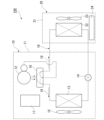
- FIG. 1 is a schematic diagram showing a schematic configuration of an air conditioner according to Embodiment 1.
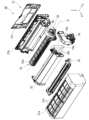
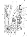
- FIG. Fig. 2 is a perspective view showing an indoor unit as a heat exchange unit according to Embodiment 1; Fig. 2 is an exploded perspective view showing an indoor unit as a heat exchange unit according to Embodiment 1;
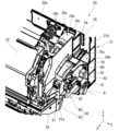
- FIG. 3 is a perspective view showing part of the indoor unit as a heat exchange unit according to Embodiment 1; 2 is an exploded perspective view showing a motor fixing portion and a motor in Embodiment 1.
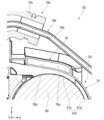
- FIG. 4 is a cross-sectional view showing part of the indoor unit as a heat exchange unit in Embodiment 1.
- FIG. FIG. 4 is a perspective view showing a second holding member of the motor fixing portion according to Embodiment 1;
- FIG. 4 is a perspective view showing a part of the indoor unit as the heat exchange unit according to the first embodiment, and showing a path along which condensed water is discharged from the inside of the hollow wall.
- 4 is a perspective view showing the inside of the hollow wall portion according to Embodiment 1.
- FIG. 4 is a cross-sectional view showing the inside of a part of the hollow wall portion in Embodiment 1.
- FIG. 8 is a perspective view showing part of an indoor unit as a heat exchange unit according to Embodiment 2;
- the drawings show the X-axis, Y-axis, and Z-axis as appropriate.
- the X-axis indicates one of the horizontal directions.
- the Y-axis indicates the other horizontal direction.
- the Z-axis indicates the vertical direction.
- the horizontal direction along the X-axis is called “front-rear direction X”
- the horizontal direction along the Y-axis is called “left-right direction Y”
- the vertical direction is called “vertical direction Z”.
- the front-rear direction X, the left-right direction Y, and the vertical direction Z are directions orthogonal to each other.
- the side of the vertical direction Z to which the Z-axis arrow points (+Z side) is defined as the upper side
- the opposite side of the vertical direction Z to which the Z-axis arrow points (-Z side) is defined as the lower side.
- the side of the front-back direction X to which the arrow of the X-axis points (+X side) is defined as the front side
- the side opposite to the side of the front-back direction X to which the arrow of the X-axis faces (-X side) is defined as the rear side.
- the left-right direction Y is the left-right direction when the indoor units of the following embodiments are viewed from the front (+X direction).
- the side of the horizontal direction Y to which the Y-axis arrow points (+Y side) is the right side
- the opposite side of the horizontal direction Y to the direction of the Y-axis arrow (-Y side) is the left side.
- FIG. 1 is a schematic diagram showing a schematic configuration of an air conditioner 100 according to Embodiment 1.
- the air conditioner 100 includes an outdoor unit 10, an indoor unit 20, and a circulation path section 18.
- the outdoor unit 10 is arranged outdoors.
- the indoor unit 20 is arranged indoors.
- the outdoor unit 10 and the indoor unit 20 are connected to each other by a circulation path part 18 through which the refrigerant 19 circulates.
- the air conditioner 100 can adjust the temperature of the indoor air by exchanging heat between the refrigerant 19 flowing through the circulation path section 18 and the indoor air in which the indoor unit 20 is arranged.
- the refrigerant 19 for example, a fluorine-based refrigerant or a hydrocarbon-based refrigerant having a low global warming potential (GWP) can be used.
- GWP global warming potential
- the outdoor unit 10 includes a housing 11, a compressor 12, a heat exchanger 13, a flow control valve 14, a blower 15, a four-way valve 16, and a controller 17.
- a compressor 12 , a heat exchanger 13 , a flow control valve 14 , a blower 15 , a four-way valve 16 , and a controller 17 are accommodated inside the housing 11 .
- the compressor 12 , the heat exchanger 13 , the flow control valve 14 and the four-way valve 16 are provided in a portion of the circulation path section 18 located inside the housing 11 .
- Compressor 12 , heat exchanger 13 , flow control valve 14 , and four-way valve 16 are connected by a portion of circulation path portion 18 located inside housing 11 .
- the four-way valve 16 is provided in a portion of the circulation path portion 18 that is connected to the discharge side of the compressor 12 .
- the four-way valve 16 can reverse the direction of the coolant 19 flowing through the circulation path portion 18 by switching a part of the circulation path portion 18 .
- the path connected by the four-way valve 16 is the path indicated by the solid line in the four-way valve 16 in FIG. 1
- the refrigerant 19 flows through the circulation path portion 18 in the direction indicated by the solid arrow in FIG.
- the path connected by the four-way valve 16 is the path indicated by the dashed line in the four-way valve 16 in FIG. 1
- the refrigerant 19 flows in the circulation path section 18 in the direction indicated by the dashed arrow in FIG.
- the indoor unit 20 includes a housing 21, a heat exchanger 22, a blower 23, and a controller 24.
- the housing 21 accommodates the heat exchanger 22, the blower 23, and the controller 24 inside.
- the indoor unit 20 is capable of a cooling operation for cooling the air in the room in which the indoor unit 20 is arranged and a heating operation for warming the air in the room in which the indoor unit 20 is arranged.
- the refrigerant 19 flowing through the circulation path portion 18 flows in the direction indicated by the solid arrow in FIG. That is, when the indoor unit 20 is in a cooling operation, the refrigerant 19 flowing through the circulation path portion 18 flows through the compressor 12, the heat exchanger 13 of the outdoor unit 10, the flow control valve 14, and the heat exchanger 22 of the indoor unit 20. in that order back to the compressor 12 .
- the heat exchanger 13 inside the outdoor unit 10 functions as a condenser
- the heat exchanger 22 inside the indoor unit 20 functions as an evaporator.
- the refrigerant 19 flowing through the circulation path portion 18 flows in the direction indicated by the dashed line in FIG.
- the refrigerant 19 flowing through the circulation path portion 18 flows through the compressor 12, the heat exchanger 22 of the indoor unit 20, the flow control valve 14, and the heat exchanger 13 of the outdoor unit 10. in that order back to the compressor 12 .
- the heat exchanger 13 inside the outdoor unit 10 functions as an evaporator
- the heat exchanger 22 inside the indoor unit 20 functions as a condenser.
- FIG. 2 is a perspective view showing the indoor unit 20.
- FIG. FIG. 3 is an exploded perspective view showing the indoor unit 20.
- FIG. FIG. 4 is a perspective view showing part of the indoor unit 20.
- the indoor unit 20 is a wall-mounted indoor unit that is fixed to an indoor wall surface.
- the indoor unit 20 has a substantially rectangular parallelepiped shape elongated in the horizontal direction Y. As shown in FIG.
- the housing 21 of the indoor unit 20 includes a box-shaped main body portion 21a that opens to the rear (-X direction), an air passage member 21b attached to the rear of the main body portion 21a, and a It has a mounting plate 21c that is fixed to the wall surface and on which the air passage member 21b is hooked, and a motor fixing portion 30 that fixes a motor 60, which will be described later.
- the motor fixing portion 30 is located on the right side (+Y direction) of the heat exchanger 22 .
- the motor fixing portion 30 is positioned forward (+X direction) at the right end portion of the air passage member 21b.
- the motor fixing portion 30 is fixed to the air passage member 21b.
- the motor fixing portion 30 is positioned inside the main body portion 21a. The motor fixing portion 30 will be described later in detail.
- the housing 21 has a first chamber 20a in which the heat exchanger 22 is housed and a second chamber 20b in which the controller 24 is housed.
- the second chamber 20b is arranged adjacent to the right side (+Y direction) of the first chamber 20a.
- the interior of the second chamber 20b is separated from the interior of the first chamber 20a in the left-right direction Y by a partition wall portion 20c.
- the partition wall 20c is configured by a portion of the air passage member 21b and a portion of the motor fixing portion 30. As shown in FIG.
- the dimension in the left-right direction Y of the second chamber 20b is smaller than the dimension in the left-right direction Y of the first chamber 20a.
- the blower 23 is arranged inside the housing 21 . Air blower 23 sends air to heat exchanger 22 . As shown in FIG. 3, the blower 23 is a cross-flow fan. More specifically, the blower 23 is a line flow fan (registered trademark). The blower 23 has an impeller 23a and a motor 60 that rotates the impeller 23a.
- the impeller 23a extends in the left-right direction Y.
- the impeller 23a rotates around a rotation axis R extending in the left-right direction Y.
- indoor air is sucked into the housing 21 through an intake port 21d provided on the upper surface of the body portion 21a of the housing 21.
- the air sucked into the housing 21 passes through the heat exchanger 22 and is blown out into the room from an air outlet (not shown) provided at the front end of the lower end of the main body 21a.
- FIG. 5 is an exploded perspective view showing the motor fixing portion 30 and the motor 60.
- the motor 60 in the first embodiment is an inner rotor type motor.
- the motor 60 includes a cylindrical motor housing 61 centered on the rotation axis R, a vibration isolating member 62a projecting rightward (+Y direction) from the motor housing 61, and a vibration isolating member 62a projecting leftward ( ⁇ Y direction) from the motor housing 61. It has a protruding vibration isolating member 62b and a shaft 63 protruding leftward from inside the motor housing 61 .
- the vibration isolating members 62a and 62b are annular with the rotation axis R as the center.
- the vibration isolating members 62 a and 62 b are fixed to the motor housing 61 .
- the vibration isolation members 62a and 62b are made of rubber, for example.
- the motor 60 is held by the motor fixing portion 30 by fixing the vibration isolating members 62 a and 62 b to the motor fixing portion 30 .
- the left end of the shaft 63 is connected to the right end of the impeller 23a. As the shaft 63 rotates around the rotation axis R, the impeller 23a is rotated around the rotation axis R.
- the heat exchanger 22 is arranged inside the housing 21 . As shown in FIG. 3, the heat exchanger 22 extends in the left-right direction Y. As shown in FIG. The heat exchanger 22 has a portion located forward (+X direction) of the impeller 23a and a portion located above the impeller 23a.
- a pipe bundle 18 a extending from the outdoor unit 10 is connected to the right (+Y side) end of the heat exchanger 22 .
- the pipe bundle 18 a forms part of the circulation path section 18 .
- the pipe bundle 18a is inserted into the housing 21 from the rear ( ⁇ X direction) of the housing 21 through the mounting plate 21c.
- the pipe bundle 18a has a plurality of refrigerant pipes 18b and a pipe cover 18c that covers the plurality of refrigerant pipes 18b.
- a plurality of refrigerant pipes 18b are exposed from the pipe cover 18c and connected to the heat exchanger 22 .
- FIG. 6 is a cross-sectional view showing part of the indoor unit 20.
- the plurality of refrigerant pipes 18 b includes refrigerant pipes 18 d located above the motor 60 .
- the refrigerant pipe 18d protrudes and extends forward (+X direction) from the pipe cover 18c.
- the refrigerant pipe 18d obliquely extends downward toward the front.
- the indoor unit 20 includes a drain pan 25 positioned below the heat exchanger 22 in the vertical direction Z.
- the drain pan 25 is a member for receiving the condensed water W produced in the heat exchanger 22 and the refrigerant pipe 18b from below.
- the condensed water W received by the drain pan 25 is discharged to the outside of the room by a drain hose (not shown).
- the drain hose for example, extends outside the room through the inside of the pipe cover 18c of the pipe bundle 18a.
- the motor fixing portion 30 in Embodiment 1 has a first holding member 40 and a second holding member 50 .
- the motor fixing portion 30 is configured by connecting a first holding member 40 and a second holding member 50 to each other in the front-rear direction X. As shown in FIG.
- the first holding member 40 and the second holding member 50 sandwich the motor 60 in the front-rear direction X to hold the motor 60 .
- the first holding member 40 includes a first covering wall portion 41 that covers the motor 60 from the rear ( ⁇ X direction), a pair of first holding wall portions 42 projecting forward (+X direction) from the first covering wall portion 41, 43 and .
- the first covering wall portion 41 extends in an arc around the rotation axis R.
- the pair of first holding wall portions 42 and 43 are arranged apart in the left-right direction Y from each other.
- the first holding wall portion 42 has a first holding concave portion 42a recessed rearward.
- the first holding wall portion 43 has a first holding concave portion 43a recessed rearward.
- the first holding recesses 42a and 43a are open on both sides in the left-right direction Y.
- the inner edge of each of the first holding recesses 42a, 43a has a substantially semicircular shape centered on the rotation axis R. As shown in FIG.
- FIG. 7 is a perspective view showing the second holding member 50.
- the second holding member 50 includes a second covering wall portion 51 that covers the motor 60 from the front (+X direction) and from above, and projects rearward ( ⁇ X direction) from the second covering wall portion 51. It has a second holding wall portion 53 and a partition wall portion 54 projecting upward and forward from the second covering wall portion 51 . Further, as shown in FIG. 5, the second holding member 50 has a second holding wall portion 52 that protrudes rearward from the second covering wall portion 51 .
- the partition wall portion 54 is a wall portion forming part of the partition wall portion 20c.
- the pair of second holding wall portions 52 and 53 are arranged apart from each other in the left-right direction Y.
- the second holding wall portion 52 has a second holding concave portion 52a recessed forward (+X direction).
- the second holding wall portion 53 has a second holding concave portion 53a recessed forward.
- Each of the second holding recesses 52a and 53a is open on both sides in the left-right direction Y.
- the inner edge of each of the second holding recesses 52a, 53a is substantially semicircular with the rotation axis R as the center.
- the first holding recess 42a and the second holding recess 52a sandwich and hold the vibration isolating member 62a of the motor 60 in the front-rear direction X. As shown in FIG.
- the first holding recess 43a and the second holding recess 53a sandwich and hold the vibration isolating member 62b of the motor 60 in the front-rear direction X. As shown in FIG. Thereby, the motor 60 is fixed to the motor fixing portion 30 .
- the second covering wall portion 51 extends from above the motor 60 toward the front (+X direction) of the motor 60 and extends in a substantially arc shape centered on the rotation axis R.
- the second covering wall portion 51 protrudes to both sides in the left-right direction Y from the partition wall portion 54 .
- FIG. 8 is a perspective view showing a part of the indoor unit 20, and shows a path along which the condensed water W is discharged from the inside of the hollow wall portion 70, which will be described later.
- the second covering wall portion 51 is formed with a notch portion 57 penetrating through the second covering wall portion 51 in the vertical direction Z.
- the notch portion 57 is provided in a portion of the second covering wall portion 51 that protrudes to the right (+Y direction) from the partition wall portion 54 .
- the notch 57 opens rightward and rearward (-X direction).
- a hole portion 31 is formed in the motor fixing portion 30 by the notch portion 57 , the second holding wall portion 52 , the first holding wall portion 42 and the first covering wall portion 41 .
- the hole portion 31 is formed in a portion of the motor fixing portion 30 located above the motor 60 .
- the hole 31 has a substantially rectangular shape elongated in the front-rear direction X when viewed from above.
- the hole 31 opens into the second chamber 20b.
- a portion of the motor 60 is exposed above the motor fixing portion 30 through the hole portion 31 . More specifically, the upper end of the right portion of the motor housing 61 is exposed above the motor fixing portion 30 through the hole portion 31 .
- a control section 24 for controlling the motor 60 is arranged above the hole 31 .
- the control unit 24 is located on the right side (+Y direction) of the partition wall portion 54 .
- the control unit 24 controls the blower 23 by controlling the motor 60 .
- the controller 24 is electrically connected to the controller 17 of the outdoor unit 10 .
- the second covering wall portion 51 has a right protruding wall portion 51a that protrudes to the right (+Y direction) of the partition wall portion 54.
- the right projecting wall portion 51a is located in front of the motor 60 (+X direction).
- the right projecting wall portion 51a extends downward from the front edge portion of the notch portion 57 .
- An upper portion of the right protruding wall portion 51a has an arc shape centering on the rotation axis R.
- the upper portion of the right protruding wall portion 51a is located forward as it goes downward.
- a lower portion of the right projecting wall portion 51a extends linearly in the vertical direction Z. As shown in FIG.
- the second covering wall portion 51 has a left protruding wall portion 51b that protrudes leftward (-Y direction) from the partition wall portion .
- the left projecting wall portion 51b covers the motor 60 from the front (+X direction) and from above.
- the left projecting wall portion 51b extends in a curved manner from above the motor 60 toward the front of the motor 60 .
- the left protruding wall portion 51 b protrudes leftward from the second holding wall portion 53 .
- the left protruding wall portion 51b has an upper wall portion 51c positioned above the motor 60 and a front wall portion 51d positioned in front of the motor 60 (+X direction).
- the upper wall portion 51c extends in the front-rear direction X while being inclined downward toward the front.
- a front portion of the upper wall portion 51c extends in an arc around the rotation axis R.
- the front wall portion 51d extends downward from the front end portion of the upper wall portion 51c.
- the front surface of the front wall portion 51d is smoothly connected to the upper surface of the upper wall portion 51c.
- An upper portion of the front wall portion 51d is arcuate with the rotation axis R as the center.
- the upper portion of the front wall portion 51d is located forward as it goes downward.
- a lower portion of the front wall portion 51d extends linearly in the vertical direction Z. As shown in FIG.
- the second holding member 50 has a rib 55 projecting forward (+X direction) from the front wall portion 51d of the left projecting wall portion 51b.
- the rib 55 has a plate shape extending in the horizontal direction Y. As shown in FIG. A right end portion of the rib 55 is connected to the partition wall portion 54 . The upper surface of the rib 55 is inclined downward toward the front. Two ribs 55 are arranged in the vertical direction Z with an interval therebetween.
- the second holding member 50 has a lower wall portion 56 that protrudes forward (+X direction) from the lower end portion of the front wall portion 51d of the left protruding wall portion 51b.
- the lower wall portion 56 is positioned below and apart from the two ribs 55 .
- the front end portion of the lower wall portion 56 is located forward of the front end portion of the rib 55 .
- the upper surface of the lower wall portion 56 is inclined downward toward the left (-Y direction).
- a left end portion of the lower wall portion 56 is positioned above the drain pan 25 .
- the second holding member 50 has a rib 58 projecting forward (+X direction) from the right projecting wall portion 51a.
- the rib 58 has a triangular plate shape when viewed in the vertical direction Z.
- a left end portion of the rib 55 is connected to the partition wall portion 54 .
- the upper surface of the rib 58 is inclined downward toward the front.
- Two ribs 58 are arranged in the vertical direction Z with an interval therebetween.
- a front end portion of the rib 58 is positioned above the drain pan 25 .
- the housing 21 has a hollow wall portion 70 located between the motor 60 and the refrigerant pipe 18d in the vertical direction Z.
- the hollow wall portion 70 forms part of the upper wall portion 51c of the left projecting wall portion 51b.
- the hollow wall portion 70 is positioned above the motor 60 in the vertical direction Z.
- the hollow wall portion 70 protrudes upward from portions of the upper wall portion 51c located on both sides in the front-rear direction X of the hollow wall portion 70 .
- the hollow wall portion 70 extends in the front-rear direction X while being inclined downward toward the front (+X direction) when viewed in the left-right direction Y. As shown in FIG.
- the upper surface of the hollow wall portion 70 is inclined with respect to a horizontal plane (XY plane) orthogonal to the vertical direction Z. As shown in FIG. As shown in FIG. 7 , the right (+Y side) end of the hollow wall portion 70 is connected to the partition wall portion 54 . The left (-Y side) end of the hollow wall portion 70 is located at the left end of the left projecting wall portion 51b. The hollow wall portion 70 is positioned above the drain pan 25 in the vertical direction Z. As shown in FIG.
- the hollow wall portion 70 includes a first portion 71 connected to the partition wall portion 54, a second portion 72 connected to the left side (-Y side) of the first portion 71, and a third portion 73 connected to the left side of the second portion 72. , has The first portion 71 protrudes forward (+X direction) from the second portion 72 and the third portion 73 . The first portion 71 protrudes upward from the second portion 72 and the third portion 73 . The vertical Z dimension of the first portion 71 is greater than the vertical Z dimension of the second portion 72 and the vertical Z dimension of the third portion 73 .
- the portion of the mold for forming the internal space 70a of the hollow wall portion 70 can be made thicker when the hollow wall portion 70 is formed by injection molding using a mold. It is easy to secure the strength of the mold.
- the hollow wall portion 70 interferes with the pipe bundle 18a and the like arranged above the hollow wall portion 70. can be suppressed.
- the upper surface of the first portion 71, the upper surface of the second portion 72, and the upper surface of the third portion 73 are inclined surfaces that are located downward toward the left (-Y direction) and forward.
- the inclination of the top surface of the second portion 72 is smaller than the inclination of the top surface of the first portion 71 and the top surface of the third portion 73 with respect to a horizontal plane (XY plane) orthogonal to the vertical direction Z.
- the dimension in the left-right direction Y of the second portion 72 is larger than the dimension in the left-right direction Y of the first portion 71 and the dimension in the left-right direction Y of the third portion 73 .
- FIG. 9 is a perspective view showing the inside of the hollow wall portion 70.
- FIG. FIG. 10 is a cross-sectional view showing the inside of part of the hollow wall portion 70.
- the hollow wall portion 70 has an opening 70c.
- An internal space 70a of the hollow wall portion 70 is connected to the outside of the hollow wall portion 70 through an opening 70c.
- the opening 70c opens to the right (+Y direction).
- the opening 70c opens on the right side of the partition wall 54 .
- the opening 70c opens into the second chamber 20b.
- the opening 70 c is the right end of the first portion 71 of the hollow wall portion 70 .
- the opening 70c extends in the front-rear direction X.
- the opening 70c extends with a slight inclination downward toward the front (+X direction).
- the front end of the opening 70c is positioned forward and below the front end of the hole 31 .
- a lower surface 70b located on the lower side is located downward toward the front (+X direction).
- the rear portion of the lower surface 70b extends linearly in a direction slightly inclined in the vertical direction Z with respect to the front-rear direction X when viewed in the left-right direction Y.
- a front portion of the lower surface 70b extends in an arc shape centered on the rotation axis R when viewed in the left-right direction Y.
- the inner surface of the hollow wall portion 70 has a first inclined surface 74a, a second inclined surface 74b, a third inclined surface 74c, and a fourth inclined surface 74d.
- the first inclined surface 74a, the second inclined surface 74b, the third inclined surface 74c, and the fourth inclined surface 74d are surfaces located on the front side (+X side) of the inner surface of the hollow wall portion .
- the inner surface of the hollow wall portion 70 located on the front side (+X side) is composed of a first inclined surface 74a, a second inclined surface 74b, a third inclined surface 74c, and a fourth inclined surface 74d. .
- the first inclined surface 74a, the second inclined surface 74b, the third inclined surface 74c, and the fourth inclined surface 74d are inclined surfaces that approach the opening 70c downward in the vertical direction Z.
- the first inclined surface 74a, the second inclined surface 74b, the third inclined surface 74c, and the fourth inclined surface 74d are oriented obliquely to the right (+Y direction) with respect to the rear ( ⁇ X direction).
- the first inclined surface 74a extends rightward (+Y direction) and obliquely forward (+X direction) from a surface located on the left side of the inner surface of the hollow wall portion 70 .
- the second inclined surface 74b extends obliquely forward to the right from the right end of the first inclined surface 74a.
- the inclination with respect to the horizontal direction Y of the second inclined surface 74b is smaller than the inclination with respect to the horizontal direction Y of the first inclined surface 74a.
- the third inclined surface 74c extends obliquely forward to the right from the right end of the second inclined surface 74b.
- the inclination with respect to the horizontal direction Y of the third inclined surface 74c is greater than the inclination with respect to the horizontal direction Y of the second inclined surface 74b.
- the fourth inclined surface 74d extends obliquely forward to the right from the right end of the third inclined surface 74c.
- the inclination with respect to the horizontal direction Y of the fourth inclined surface 74d is smaller than the inclination with respect to the horizontal direction Y of the third inclined surface 74c.
- the right end of the fourth inclined surface 74d is connected to the edge of the front end of the opening 70c.
- the first inclined surface 74 a is part of the inner surface of the third portion 73 .
- the second inclined surface 74 b is part of the inner surface of the second portion 72 .
- the third inclined surface 74 c and the fourth inclined surface 74 d are part of the inner surface of the first portion 71 .
- condensation water W is generated on the outer surface of the refrigerant pipe 18d.
- a part of the condensed water W generated on the outer surface of the refrigerant pipe 18 d drops, for example, on the upper surface of the hollow wall portion 70 .
- the condensed water W that has fallen on the upper surface of the hollow wall portion 70 flows forward (+X direction) and downward due to gravity along the upper surface of the hollow wall portion 70 that is inclined with respect to the horizontal plane (XY plane).
- the condensed water W flowing along the upper surface of the hollow wall portion 70 drops downward from the front end portion of the hollow wall portion 70 and flows further forward and downward along the front wall portion 51d of the left projecting wall portion 51b.
- a rib 55 is provided on the front wall portion 51d, and the upper surface of the rib 55 is inclined downward toward the front. flows forward and downward along the top surface of the
- the condensed water W that has flowed along the front wall portion 51 d while flowing on the upper surface of the rib 55 drops onto the upper surface of the lower wall portion 56 .
- Condensed water W flows leftward ( ⁇ Y direction) and downward along the upper surface of the lower wall portion 56 , falls from the left end portion of the lower wall portion 56 , and flows into the drain pan 25 .
- the condensed water W generated in the refrigerant pipe 18d as described above drops onto the upper surface of the hollow wall portion 70, the air in the internal space 70a of the hollow wall portion 70 is cooled, and as shown in FIG. Condensed water W may occur in the internal space 70 a of the 70 .
- the condensed water W in the hollow wall portion 70 flows forward (+X direction) and downward along the lower surface 70b.
- the condensed water W that has flowed along the lower surface 70b is part of the inner surface of the hollow wall portion 70 located on the front side, that is, the first inclined surface 74a, the second inclined surface 74b, the third inclined surface 74c, and the third inclined surface 74c. 4 slanted surfaces 74d.
- the condensed water W coming into contact with any inclined surface flows downward and rightward (+Y direction) along the contacting inclined surface due to gravity to the front end of the opening 70c.
- the condensed water W coming into contact with the second inclined surface 74b flows along the second inclined surface 74b, the third inclined surface 74c, and the fourth inclined surface 74d in this order, and reaches the front end of the opening 70c. flow to the department.
- the condensed water W that has flowed to the front end of the opening 70c is discharged to the outside of the hollow wall 70 through the opening 70c.
- the condensed water W discharged from the hollow wall portion 70 flows forward (+X direction) and downward along the left end portion of the right projecting wall portion 51a and the partition wall portion 54 due to gravity.
- the condensed water W discharged from the hollow wall 70 flows into the hole 31. is suppressed.
- Condensed water W flowing along the left end of the right projecting wall portion 51 a and the partition wall portion 54 contacts the upper surface of the rib 58 . Since the upper surfaces of the ribs 58 are inclined downward toward the front (+X direction), the condensed water W flows forward and obliquely downward on the upper surfaces of the ribs 58 .
- the condensed water W that has flowed diagonally forward and downward on the upper surface of the rib 58 drops downward from the front end portion of the rib 58 and flows into the drain pan 25 .
- the condensed water W produced on the outer surface of the refrigerant pipe 18 d and the condensed water W produced in the internal space 70 a of the hollow wall portion 70 flow on the surface of the motor fixing portion 30 and flow inside the drain pan 25 . led to.
- the condensed water W can be collected in the drain pan 25 by the motor fixing portion 30 .
- the condensed water W collected in the drain pan 25 is discharged outside through a drain hose (not shown).
- the housing 21 of the indoor unit 20 has the hollow wall portion 70 positioned between the motor 60 and the refrigerant pipe 18d. Therefore, the condensed water W generated on the outer surface of the refrigerant pipe 18 d can be blocked by the hollow wall portion 70 , and the reaching of the motor 60 by the condensed water W generated on the outer surface of the refrigerant pipe 18 d can be suppressed. As a result, it is possible to prevent the motor 60 from being splashed by the condensed water W generated on the outer surface of the refrigerant pipe 18d.
- the presence of air in the internal space 70a of the hollow wall portion 70 can suppress heat transfer between the space on the motor 60 side and the space on the refrigerant pipe 18d side with the hollow wall portion 70 interposed therebetween. Therefore, even if the condensed water W generated in the refrigerant pipe 18 d comes into contact with the hollow wall portion 70 , cooling of the air in the space in which the motor 60 is accommodated by the condensed water W can be suppressed. In Embodiment 1, cooling of the air in the space located below the upper wall portion 51c of the left projecting wall portion 51b can be suppressed.
- Embodiment 1 by forming part of the housing 21 as the hollow wall portion 70, it is possible to prevent the condensed water W from being applied to the motor 60, so that the housing 21 is separately insulated. No need to attach materials. More specifically, it is not necessary to attach a heat insulating material or the like to the upper surface of the left projecting wall portion 51b, the lower surface of the left projecting wall portion 51b, or the like. Therefore, an increase in manufacturing cost of the indoor unit 20 can be suppressed. As described above, according to Embodiment 1, it is possible to suppress the increase in the manufacturing cost of the indoor unit 20 while suppressing the condensation water W from being applied to the motor 60 .
- the hollow wall portion 70 is positioned above the motor 60 in the vertical direction Z. Therefore, the hollow wall portion 70 can suitably block the condensed water W dropping from the refrigerant pipe 18d.
- the upper surface of the hollow wall portion 70 is inclined with respect to the horizontal plane (XY plane) orthogonal to the vertical direction Z. Therefore, even if the condensed water W generated in the refrigerant pipe 18 d falls on the upper surface of the hollow wall portion 70 , the condensed water W can flow along the upper surface of the hollow wall portion 70 due to gravity. As a result, it is possible to prevent the condensed water W from remaining on the upper surface of the hollow wall portion 70 . Therefore, the internal space 70a of the hollow wall portion 70 can be prevented from being cooled by the condensed water W, and the formation of the condensed water W in the internal space 70a of the hollow wall portion 70 can be prevented. In Embodiment 1, the condensed water W that has fallen on the upper surface of the hollow wall portion 70 flows into the drain pan 25 as described above and is discharged to the outside through a drain hose (not shown).
- the hollow wall portion 70 has the opening portion 70c. Therefore, even if the condensed water W is produced inside the hollow wall portion 70, the condensed water W produced inside the hollow wall portion 70 can be discharged to the outside of the hollow wall portion 70 through the opening 70c. As a result, cooling of the air in the internal space 70a of the hollow wall portion 70 can be suppressed, and cooling of the air in the accommodation space of the motor 60 via the air in the internal space 70a can be suppressed. Therefore, it is possible to further suppress the formation of condensed water W in the accommodation space of the motor 60 .
- the inner surface of the hollow wall portion 70 has a first inclined surface 74a, a second inclined surface 74b, and a third inclined surface as inclined surfaces that approach the opening 70c as it goes downward in the vertical direction Z. It has a surface 74c and a fourth inclined surface 74d. Therefore, the condensed water W generated in the hollow wall portion 70 can flow toward the opening portion 70c along each inclined surface using gravity. As a result, the condensed water W generated inside the hollow wall portion 70 can be preferably discharged to the outside of the hollow wall portion 70 through the opening 70c. Therefore, the formation of condensed water W in the accommodation space of the motor 60 can be more preferably suppressed.
- each inclined surface can guide the condensed water W to the front end of the opening 70c.
- the condensed water W discharged from the front end of the opening 70c flows forward (+X) due to gravity. Since the front end of the opening 70c is positioned forward of the front end of the hole 31 exposing a portion of the motor 60, the condensed water W discharged from the opening 70c is prevented from flowing into the hole 31. be. As a result, it is possible to prevent the condensed water W generated inside the hollow wall portion 70 from splashing onto the portion of the motor 60 exposed through the hole portion 31 .
- the housing 21 includes a first chamber 20a in which the heat exchanger 22 is accommodated, and a second chamber 20b in which the controller 24 is accommodated and which is partitioned from the first chamber 20a. and have The opening 70c opens into the second chamber 20b. Therefore, even if the heat exchanger 22 is cooled by the refrigerant 19 and the temperature inside the first chamber 20a is lowered, the cooled air inside the first chamber 20a will flow inside the hollow wall portion 70. Inflow can be suppressed. Thereby, it is possible to suppress the temperature of the air in the hollow wall portion 70 from decreasing. Therefore, the formation of condensed water W inside the hollow wall portion 70 can be further suppressed, and the formation of condensed water W inside the accommodation space of the motor 60 can be further suppressed.
- the hollow wall portion 70 is positioned above the drain pan 25 in the vertical direction Z. Therefore, the condensed water W that has fallen from the refrigerant pipe 18d onto the upper surface of the hollow wall portion 70 and the condensed water W that has formed inside the hollow wall portion 70 are caused to flow downward by gravity as described above. It is easy to flow the water W into the drain pan 25. - ⁇ As a result, the condensed water W can be easily discharged to the outside of the room via a drain hose (not shown).
- the housing 21 has the motor fixing portion 30 that fixes the motor 60 .
- the motor fixing portion 30 has a hollow wall portion 70 . Therefore, it is easy to arrange the hollow wall portion 70 at a suitable position with respect to the motor 60 . Accordingly, the hollow wall portion 70 can easily suppress the condensation water W from splashing onto the motor 60 .
- the heat exchange unit having the hollow wall portion 70 is the indoor unit 20 of the air conditioner 100 .
- the refrigerant pipe 18 b is likely to be arranged near the motor 60 of the blower 23 due to the layout of each component inside the housing 21 . Therefore, the effect of the hollow wall portion 70 described above can be obtained more effectively in the indoor unit 20 .
- FIG. 11 is a perspective view showing part of the indoor unit 220 according to the second embodiment.
- the description may be omitted by appropriately assigning the same reference numerals to the same configurations as those of the above-described embodiment.
- the indoor unit 220 includes a heat insulating material 280 that closes the opening 70c of the hollow wall portion 70.
- heat insulating material 280 is sheet-like.
- the material forming the heat insulating material 280 is not particularly limited as long as it is a material with relatively low thermal conductivity. Examples of the material forming the heat insulating material 280 include urethane.
- Other configurations of each part of the indoor unit 220 are the same as other configurations of each part of the indoor unit 20 of the first embodiment.
- the heat insulating material 280 can prevent the air inside the hollow wall portion 70 from being cooled. As a result, it is possible to suppress the formation of condensed water W inside the hollow wall portion 70 . Further, when the condensed water W is generated in the hollow wall portion 70, the condensed water W is not discharged from the opening portion 70c, so that it is possible to suppress the condensed water W from splashing onto the exposed portion of the motor 60 from the hole portion 31. . Further, if the heat insulating material 280 is made of, for example, urethane to absorb the condensed water W, the heat insulating material 280 can absorb the condensed water W generated inside the hollow wall portion 70 .
- the condensed water W generated in the hollow wall portion 70 flows into the opening 70c, so that the heat insulating material 280 can absorb the condensed water W appropriately. .
- the condensed water W absorbed by the heat insulating material 280 evaporates outside the hollow wall portion 70, for example.
- the heat insulating material 280 that can cover the opening 70c of the hollow wall portion 70 should be provided. Therefore, compared to the case where the hollow wall portion 70 is not provided, the amount of heat insulating material 280 used can be reduced. As a result, an increase in manufacturing cost of the indoor unit 220 can be suppressed.
- the hollow wall portion may be arranged at any position and may have any shape.
- the hollow wall portion may be positioned between the motor and the refrigerant pipe in a direction that intersects the vertical direction.
- a plurality of hollow wall portions may be provided.
- the opening of the hollow wall may open in any direction.
- the hollow wall may have no openings.
- the hollow wall portion may be provided in a portion of the housing other than the motor fixing portion.
- Heat exchange units with hollow walls are not limited to indoor units of air conditioners.
- the heat exchange unit may be a device provided with a housing, a heat exchanger, refrigerant pipes, and a blower, and may be an outdoor unit of an air conditioner or an outdoor unit of a water heater.
Landscapes
- Engineering & Computer Science (AREA)
- Chemical & Material Sciences (AREA)
- Combustion & Propulsion (AREA)
- Mechanical Engineering (AREA)
- General Engineering & Computer Science (AREA)
- Air Filters, Heat-Exchange Apparatuses, And Housings Of Air-Conditioning Units (AREA)
- Other Air-Conditioning Systems (AREA)
- Motor Or Generator Frames (AREA)
Priority Applications (5)
| Application Number | Priority Date | Filing Date | Title |
|---|---|---|---|
| JP2023570568A JP7570537B2 (ja) | 2021-12-28 | 2021-12-28 | 熱交換ユニット、および空気調和機 |
| PCT/JP2021/048768 WO2023127086A1 (ja) | 2021-12-28 | 2021-12-28 | 熱交換ユニット、および空気調和機 |
| DE112021008557.3T DE112021008557T5 (de) | 2021-12-28 | 2021-12-28 | Wärmetauscher-Einheit und Klimaanlage |
| US18/693,241 US20240384889A1 (en) | 2021-12-28 | 2021-12-28 | Heat exchange unit and air conditioner |
| CN202180104010.8A CN118382782A (zh) | 2021-12-28 | 2021-12-28 | 热交换单元以及空调机 |
Applications Claiming Priority (1)
| Application Number | Priority Date | Filing Date | Title |
|---|---|---|---|
| PCT/JP2021/048768 WO2023127086A1 (ja) | 2021-12-28 | 2021-12-28 | 熱交換ユニット、および空気調和機 |
Publications (1)
| Publication Number | Publication Date |
|---|---|
| WO2023127086A1 true WO2023127086A1 (ja) | 2023-07-06 |
Family
ID=86998401
Family Applications (1)
| Application Number | Title | Priority Date | Filing Date |
|---|---|---|---|
| PCT/JP2021/048768 Ceased WO2023127086A1 (ja) | 2021-12-28 | 2021-12-28 | 熱交換ユニット、および空気調和機 |
Country Status (5)
| Country | Link |
|---|---|
| US (1) | US20240384889A1 (https=) |
| JP (1) | JP7570537B2 (https=) |
| CN (1) | CN118382782A (https=) |
| DE (1) | DE112021008557T5 (https=) |
| WO (1) | WO2023127086A1 (https=) |
Citations (2)
| Publication number | Priority date | Publication date | Assignee | Title |
|---|---|---|---|---|
| WO2006090564A1 (ja) * | 2005-02-24 | 2006-08-31 | Mitsubishi Denki Kabushiki Kaisha | 天井埋込型空気調和機 |
| JP2011058779A (ja) * | 2009-09-14 | 2011-03-24 | Sharp Corp | 空気調和機の室内機 |
Family Cites Families (3)
| Publication number | Priority date | Publication date | Assignee | Title |
|---|---|---|---|---|
| JP2011074886A (ja) | 2009-10-01 | 2011-04-14 | Panasonic Corp | ファンモータ支持部材と空気調和機 |
| US10139115B2 (en) * | 2010-03-26 | 2018-11-27 | Trane International Inc. | Air handling unit with inner wall space |
| US20230314041A1 (en) * | 2022-04-01 | 2023-10-05 | Johnson Control Tyco IP Holdings LLP | Heater arrangement for hvac system |
-
2021
- 2021-12-28 DE DE112021008557.3T patent/DE112021008557T5/de active Pending
- 2021-12-28 US US18/693,241 patent/US20240384889A1/en active Pending
- 2021-12-28 WO PCT/JP2021/048768 patent/WO2023127086A1/ja not_active Ceased
- 2021-12-28 CN CN202180104010.8A patent/CN118382782A/zh active Pending
- 2021-12-28 JP JP2023570568A patent/JP7570537B2/ja active Active
Patent Citations (2)
| Publication number | Priority date | Publication date | Assignee | Title |
|---|---|---|---|---|
| WO2006090564A1 (ja) * | 2005-02-24 | 2006-08-31 | Mitsubishi Denki Kabushiki Kaisha | 天井埋込型空気調和機 |
| JP2011058779A (ja) * | 2009-09-14 | 2011-03-24 | Sharp Corp | 空気調和機の室内機 |
Also Published As
| Publication number | Publication date |
|---|---|
| CN118382782A (zh) | 2024-07-23 |
| DE112021008557T5 (de) | 2024-10-10 |
| JPWO2023127086A1 (https=) | 2023-07-06 |
| US20240384889A1 (en) | 2024-11-21 |
| JP7570537B2 (ja) | 2024-10-21 |
Similar Documents
| Publication | Publication Date | Title |
|---|---|---|
| JP2023071327A (ja) | 室内機 | |
| WO2013146005A1 (ja) | 空気調和装置の室内機 | |
| JP6468303B2 (ja) | 空気調和装置の室内機 | |
| WO2023135845A1 (ja) | 室内機、および空気調和機 | |
| JP2014005954A (ja) | 空気調和装置の室内機 | |
| JP2015072075A (ja) | 空気調和機の室外機 | |
| CN101523122B (zh) | 空调装置的室内单元 | |
| CN109983282B (zh) | 空调装置的室内机组 | |
| WO2023127086A1 (ja) | 熱交換ユニット、および空気調和機 | |
| CN103727590B (zh) | 立式空调室内机 | |
| JP5192558B2 (ja) | 空気調和機 | |
| JP2010158948A (ja) | 車両用空調ユニット | |
| JP3731067B2 (ja) | 空気調和装置の室内機 | |
| JP7734853B2 (ja) | 熱交換器、熱交換ユニット、および空気調和機 | |
| WO2006001323A1 (ja) | 空気調和機 | |
| WO2020179007A1 (ja) | 空気調和機の室内機 | |
| EP1052457B1 (en) | Indoor unit for air conditioner | |
| JP7374356B2 (ja) | 室外機および冷凍サイクル装置 | |
| JP4535062B2 (ja) | 冷却装置 | |
| CN217715188U (zh) | 空调机 | |
| JP3998030B2 (ja) | 天井設置型空気調和装置 | |
| TR2024005743T2 (tr) | Isı değiştirme ünitesi ve klima | |
| JP7837439B2 (ja) | 空気調和機 | |
| JP7089185B2 (ja) | 空気処理装置用の付加ユニット、及び空気処理ユニット | |
| WO2005052457A1 (ja) | 空気調和装置 |
Legal Events
| Date | Code | Title | Description |
|---|---|---|---|
| 121 | Ep: the epo has been informed by wipo that ep was designated in this application |
Ref document number: 21969968 Country of ref document: EP Kind code of ref document: A1 |
|
| WWE | Wipo information: entry into national phase |
Ref document number: 2023570568 Country of ref document: JP |
|
| WWE | Wipo information: entry into national phase |
Ref document number: 18693241 Country of ref document: US |
|
| WWE | Wipo information: entry into national phase |
Ref document number: 202180104010.8 Country of ref document: CN |
|
| WWE | Wipo information: entry into national phase |
Ref document number: 2401002981 Country of ref document: TH |
|
| WWE | Wipo information: entry into national phase |
Ref document number: 202427036909 Country of ref document: IN Ref document number: 2024/005743 Country of ref document: TR |
|
| WWE | Wipo information: entry into national phase |
Ref document number: 112021008557 Country of ref document: DE |
|
| 122 | Ep: pct application non-entry in european phase |
Ref document number: 21969968 Country of ref document: EP Kind code of ref document: A1 |